US7150929B2 - Fuel cell coolers with inverse flow and condensation zone - Google Patents
Fuel cell coolers with inverse flow and condensation zoneDownload PDFInfo
- Publication number
- US7150929B2 US7150929B2US11/025,231US2523104AUS7150929B2US 7150929 B2US7150929 B2US 7150929B2US 2523104 AUS2523104 AUS 2523104AUS 7150929 B2US7150929 B2US 7150929B2
- Authority
- US
- United States
- Prior art keywords
- fuel
- zone
- coolant
- pass
- adjacent
- Prior art date
- Legal status (The legal status is an assumption and is not a legal conclusion. Google has not performed a legal analysis and makes no representation as to the accuracy of the status listed.)
- Expired - Lifetime, expires
Links
Images


Classifications
- H—ELECTRICITY
- H01—ELECTRIC ELEMENTS
- H01M—PROCESSES OR MEANS, e.g. BATTERIES, FOR THE DIRECT CONVERSION OF CHEMICAL ENERGY INTO ELECTRICAL ENERGY
- H01M8/00—Fuel cells; Manufacture thereof
- H01M8/02—Details
- H01M8/0202—Collectors; Separators, e.g. bipolar separators; Interconnectors
- H01M8/0258—Collectors; Separators, e.g. bipolar separators; Interconnectors characterised by the configuration of channels, e.g. by the flow field of the reactant or coolant
- H01M8/0263—Collectors; Separators, e.g. bipolar separators; Interconnectors characterised by the configuration of channels, e.g. by the flow field of the reactant or coolant having meandering or serpentine paths
- H—ELECTRICITY
- H01—ELECTRIC ELEMENTS
- H01M—PROCESSES OR MEANS, e.g. BATTERIES, FOR THE DIRECT CONVERSION OF CHEMICAL ENERGY INTO ELECTRICAL ENERGY
- H01M8/00—Fuel cells; Manufacture thereof
- H01M8/04—Auxiliary arrangements, e.g. for control of pressure or for circulation of fluids
- H—ELECTRICITY
- H01—ELECTRIC ELEMENTS
- H01M—PROCESSES OR MEANS, e.g. BATTERIES, FOR THE DIRECT CONVERSION OF CHEMICAL ENERGY INTO ELECTRICAL ENERGY
- H01M8/00—Fuel cells; Manufacture thereof
- H01M8/02—Details
- H01M8/0202—Collectors; Separators, e.g. bipolar separators; Interconnectors
- H01M8/0267—Collectors; Separators, e.g. bipolar separators; Interconnectors having heating or cooling means, e.g. heaters or coolant flow channels
- H—ELECTRICITY
- H01—ELECTRIC ELEMENTS
- H01M—PROCESSES OR MEANS, e.g. BATTERIES, FOR THE DIRECT CONVERSION OF CHEMICAL ENERGY INTO ELECTRICAL ENERGY
- H01M8/00—Fuel cells; Manufacture thereof
- H01M8/04—Auxiliary arrangements, e.g. for control of pressure or for circulation of fluids
- H01M8/04007—Auxiliary arrangements, e.g. for control of pressure or for circulation of fluids related to heat exchange
- H01M8/04067—Heat exchange or temperature measuring elements, thermal insulation, e.g. heat pipes, heat pumps, fins
- H01M8/04074—Heat exchange unit structures specially adapted for fuel cell
- H—ELECTRICITY
- H01—ELECTRIC ELEMENTS
- H01M—PROCESSES OR MEANS, e.g. BATTERIES, FOR THE DIRECT CONVERSION OF CHEMICAL ENERGY INTO ELECTRICAL ENERGY
- H01M8/00—Fuel cells; Manufacture thereof
- H01M8/04—Auxiliary arrangements, e.g. for control of pressure or for circulation of fluids
- H01M8/04276—Arrangements for managing the electrolyte stream, e.g. heat exchange
- H—ELECTRICITY
- H01—ELECTRIC ELEMENTS
- H01M—PROCESSES OR MEANS, e.g. BATTERIES, FOR THE DIRECT CONVERSION OF CHEMICAL ENERGY INTO ELECTRICAL ENERGY
- H01M8/00—Fuel cells; Manufacture thereof
- H01M8/24—Grouping of fuel cells, e.g. stacking of fuel cells
- H01M8/241—Grouping of fuel cells, e.g. stacking of fuel cells with solid or matrix-supported electrolytes
- H01M8/2425—High-temperature cells with solid electrolytes
- H—ELECTRICITY
- H01—ELECTRIC ELEMENTS
- H01M—PROCESSES OR MEANS, e.g. BATTERIES, FOR THE DIRECT CONVERSION OF CHEMICAL ENERGY INTO ELECTRICAL ENERGY
- H01M8/00—Fuel cells; Manufacture thereof
- H01M8/10—Fuel cells with solid electrolytes
- H01M2008/1095—Fuel cells with polymeric electrolytes
- H—ELECTRICITY
- H01—ELECTRIC ELEMENTS
- H01M—PROCESSES OR MEANS, e.g. BATTERIES, FOR THE DIRECT CONVERSION OF CHEMICAL ENERGY INTO ELECTRICAL ENERGY
- H01M8/00—Fuel cells; Manufacture thereof
- H01M8/08—Fuel cells with aqueous electrolytes
- H01M8/086—Phosphoric acid fuel cells [PAFC]
- Y—GENERAL TAGGING OF NEW TECHNOLOGICAL DEVELOPMENTS; GENERAL TAGGING OF CROSS-SECTIONAL TECHNOLOGIES SPANNING OVER SEVERAL SECTIONS OF THE IPC; TECHNICAL SUBJECTS COVERED BY FORMER USPC CROSS-REFERENCE ART COLLECTIONS [XRACs] AND DIGESTS
- Y02—TECHNOLOGIES OR APPLICATIONS FOR MITIGATION OR ADAPTATION AGAINST CLIMATE CHANGE
- Y02E—REDUCTION OF GREENHOUSE GAS [GHG] EMISSIONS, RELATED TO ENERGY GENERATION, TRANSMISSION OR DISTRIBUTION
- Y02E60/00—Enabling technologies; Technologies with a potential or indirect contribution to GHG emissions mitigation
- Y02E60/30—Hydrogen technology
- Y02E60/50—Fuel cells
Definitions
- This inventionrelates to a fuel cell power plant system which converts fuel to useable heat and electric power, employing a fuel cell stack which has fuel flow field and cooler planforms that promote a high degree of electrolyte condensation (which may be phosphoric acid in a fuel cell stack employing a phosphoric acid electrolyte, or may be a free acid electrolyte in a high temperature polymer electrolyte membrane (HTPEM) fuel cell stack) while maintaining a sufficiently high reaction temperature to mitigate CO poisoning of the catalysts.
- a fuel cell stackwhich has fuel flow field and cooler planforms that promote a high degree of electrolyte condensation (which may be phosphoric acid in a fuel cell stack employing a phosphoric acid electrolyte, or may be a free acid electrolyte in a high temperature polymer electrolyte membrane (HTPEM) fuel cell stack) while maintaining a sufficiently high reaction temperature to mitigate CO poisoning of the catalysts.
- HTPhigh temperature polymer electrolyte membrane
- cooler plates interposed between groups of fuel cellshave a simple serpentine cooler flow path and utilize water coolant. Liquid water enters the cooler plates and a two-phase, water/steam mixture exits the cooler plates. A small fraction of the heat removal is due to increasing the sensible heat of the water as it increases to its boiling temperature, and a major fraction of heat removal is due to the latent heat of evaporation of liquid water to steam.
- U.S. Pat. No. 3,969,145describes such a coolant system.
- the useful life of the fuel cellis determined principally by the rate at which phosphoric acid evaporates into the reactant gases and is not condensed back to a liquid before exiting the fuel cells.
- Non-reactive acid condensation zones at the reactant gas exits of the fuel cellsminimize acid loss due to evaporation and thereby maximize life of the fuel cell stack.
- Such condensation zonesare taught in U.S. Pat. Nos. 4,345,008 and 4,414,291, and in PCT patent publication WO 00/36680.
- the condensation zonesshould be below 140° C. (280° F.) in order to assure sufficient condensation of electrolyte so that the fuel cell stack will perform for at least ten years, which in turn requires that the coolant inlet temperature must be less than 140° C. (280° F.) in prior systems.
- a competing problem in a phosphoric acid fuel cell stackis that the reformate fuel provided by a fuel processing system which converts various hydrocarbon fuels to hydrogen, such as a steam reforming fuel processor, contains between 0.3% and 1.0% carbon monoxide (CO), which is a poison to the anode catalyst and impedes the oxidation of hydrogen at the anode.
- COcarbon monoxide
- the extent of poisoningis a function of the concentration of CO and cell temperature.
- the temperature within the electrochemically active portion of each cellmust be kept above 150° C. (300° F.) in order to provide reliable fuel cell performance.
- the temperature suited for condensationis lower than the temperature required for CO tolerance.
- Objects of the inventioninclude: providing for a high degree of liquid condensation in fuel cell stacks fueled by reformate containing carbon monoxide, without reducing cell performance as a result of carbon monoxide poisoning (CO); minimizing electrolyte loss in a phosphoric acid or high temperature polymer electrolyte membrane (HTPEM) fuel cell stack; maximizing the life of a phosphoric acid or HTPEM fuel cell stack; and achieving, in a phosphoric acid or HTPEM fuel cell, low temperatures required for condensing electrolyte which evaporates into the reactant gases, together with a higher temperature required to prevent CO poisoning of the anodes of the fuel cell stack.
- COcarbon monoxide poisoning
- the planform of fuel cell electrode assembliesinclude a non-reactive zone which is maintained at a temperature sufficiently low so as to condense substantially all of the liquid which has evaporated into the reactant gas streams, allowing said liquid to re-migrate into the fuel cells.
- the electrolyteis phosphoric acid which is condensed in the non-reaction zone, but the invention may be used to condense electrolyte in HTPEM fuel cells.
- the coolant inletsare adjacent the non-reactive zones of the fuel cells, the resulting low temperatures promoting condensation of electrolyte which has evaporated into the reactant gases of the fuel cells.
- Coolant in a second zone, adjacent to the non-reactive zoneflows generally toward the non-reactive zone assuring the edge of the reactive zone adjacent to the non-reactive zone will be at a temperature high enough to mitigate CO poisoning of the catalysts.
- the coolantthereafter flows generally away from said non-reactive zone.
- the inventionmay be incorporated in a fuel cell having a three-pass fuel flow field, the first fuel pass generally overlapping the third zone remote from the non-active zone, the second fuel pass being in a second zone, adjacent to the non-reactive zone, and the third fuel pass being within the non-reactive zone.
- the oxidant reactant gasenters the third zone, and flows through the second zone and the non-reactive zone to the oxidant reactant gas exit, which is adjacent to the coolant inlet.
- Other embodimentsare disclosed hereinafter.
- the inventionalso may be used in other fuel cells containing free electrolyte to condense other electrolytes from the reactant gas exiting the fuel cell.
- the inventionmay be used with a single phase coolant, such as water, or a two-phase coolant, such as a water/steam mixture.
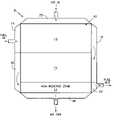
- FIG. 1is a simplified, stylized planform of the air and fuel flow fields of fuel cells employing the invention, indicating the non-reactive zone.
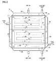
- FIG. 2is a planform as in FIG. 1 , with the coolant flow channels illustrated thereon.
- FIG. 3is a variation of the planform in FIG. 2 .
- FIG. 4is a simplified, stylized schematic diagram of a coolant flow field overlaid on a planform having a two-pass air flow field.
- a fuel cell stack 9includes a plurality of fuel cells 10 having three zones 11 – 13 . Each of the zones 11 – 13 generally overlaps one of three fuel flow passes in the fuel flow channels. Fuel enters through a fuel inlet manifold 17 , and flows to the right (as seen in FIG. 1 ) through the fuel flow fields associated with the third zones 13 . Then the fuel flows through a turnaround manifold 19 and then to the left (as seen in FIG. 1 ) through the fuel flow fields associated with the second zones 12 , to a second turnaround manifold 20 , and then to the right (as seen in FIG. 1 ) through the flow fields associated with the first, non-reactive zones 11 , and outwardly through a fuel exit manifold 22 .
- the first zones 11are non-reactive because the portion of each fuel cell comparable with the first zones 11 do not have a cathode catalyst and therefore do not react with the reactant gases.
- the oxidant reactant gassuch as air
- the fuel cell stack 9 planform configurationis shown as in FIG. 1 , but in addition, includes the pattern of coolant flow channels in cooler plates, which typically are placed between groups of several fuel cells, throughout the fuel cell stack. For instance, in a 200 kW fuel cell system, there may be 35 coolers, placed between each group of eight fuel cells in a stack of 272 fuel cells.
- the cooler plates in this embodimentare fed by external coolant manifolds, including a coolant inlet manifold 29 and a coolant outlet manifold 30 .
- the coolantflows adjacent the first, non-reactive zones 11 to the left and then the right through coolant flow channel segments 30 , 31 respectively.
- the coolest coolantis provided adjacent non-reactive zones so as to cause significant condensation of electrolyte which may have evaporated into the reactant gases, as the reactant gases flow out of each of the fuel cells, without the cool temperature causing CO poisoning.
- the coolantthen flows through segments 33 of the coolant flow channels adjacent the first zones 11 , the second zones 12 and the far side of the third zones 13 .
- the coolantthen flows through segments 34 of the coolant flow channels adjacent the third zones 13 and the second zones 12 .
- a “substack”is a group of cells between two cooler plates.
- the center cells within a substackare the hottest and the cells adjacent the coolers are the coolest. Acid loss is proportional to the local temperature at the exit of each pass of fuel or air. Extensions 33 – 34 lower the local temperature at the exit of the first fuel pass and thus reduce acid loss into the first fuel pass relative to a cooler plate design that does not have extensions 33 – 34 .
- the fuel reactant of the several cells of a substackare well mixed together in fuel turn manifold 19 . This results in all cells within the substack receiving a uniform quantity of acid. The hot cells receive less acid than they lost and the cold cells receive more acid than they lost.
- the coolantthen flows through serpentine flow segments 37 – 41 in a direction which is the same as the direction of the oxidant reactant gas, from top to bottom, as seen in FIG. 1 , adjacent the second zones 12 .
- the flows adjacent the first, non-reactive, condensation zones 11 and the flows adjacent the second zones 12are such as to provide a sharp temperature gradient at the interface between the zones 11 and 12 , so that the reactive portion of the fuel cell is well above 150° C. (300° F.) to avoid CO poisoning, while condensation will occur in the non-reactive zone at a temperature below 140° C. (280° F.).
- the coolantthen flows in a serpentine fashion through a plurality of segments 45 – 50 in a direction which is generally opposite to the flow of oxidant adjacent the third zones 13 , to the coolant outlet manifold 30 .
- coolant flow channelsmay be established so that segment 33 joins directly with segment 50 , as in FIG. 3 , and coolant flow in the third zone 13 will be toward the first zone 11 .
- the coolant exit manifold 30may then be to the left of the air inlet manifold 25 .
- the inventionmay be practiced by having the segment 33 remain adjacent the second zones 12 and feed the segments 37 directly, thus eliminating the segments 34 and the extension of the segments 33 in the third zones.
- Thishelps to provide a sharp temperature gradient between those portions of the fuel cells which are adjacent the segments 41 and those portions of the fuel cells which are adjacent to the segments 31 , thus assuring a high enough temperature to avoid severe CO poisoning of the anodes adjacent the second zones and a low enough temperature for significant condensation of electrolyte adjacent the first zones 11 .
- Two-pass aircan be utilized with multiple pass fuel, as illustrated schematically in FIG. 4 , wherein:
- FImeans fuel inlet
- FT 1means first fuel turn
- FT 2means second fuel turn
- a 1means air inlet
- CIcoolant inlet
- CEcoolant exit
- Alternative fuel configurationsconsisting of more than three passes can be accommodated as long as the coolant enters the last fuel pass, flows generally counter to the oxidant flow in the last fuel pass, and passes through the next-to-last fuel pass (the fuel pass adjacent to the last fuel pass) in the same general direction as the oxidant flow in the next-to-last fuel pass.
- US 2004/0028976A1describes a modified polybenzimidazole (PBI) membrane and US 2004/0127588A1 describes a polymer membrane based on polyazoles. Additional phosphoric acid or polyphosphoric acid, free acids, may be added to fuel cells which incorporate these high temperature polymer electrolyte membranes to enhance their electrochemical performance or to enhance their life.
- the inventionmay be used to condense such electrolytes as well as phosphoric acid.
- the present inventionmay be used with single phase coolant, such as water, or with dual phase coolant, such as a water/steam mixture.
Landscapes
- Life Sciences & Earth Sciences (AREA)
- Engineering & Computer Science (AREA)
- Manufacturing & Machinery (AREA)
- Sustainable Development (AREA)
- Sustainable Energy (AREA)
- Chemical & Material Sciences (AREA)
- Chemical Kinetics & Catalysis (AREA)
- Electrochemistry (AREA)
- General Chemical & Material Sciences (AREA)
- Fuel Cell (AREA)
Abstract
Description
Claims (5)
Priority Applications (9)
| Application Number | Priority Date | Filing Date | Title |
|---|---|---|---|
| US11/025,231US7150929B2 (en) | 2004-12-29 | 2004-12-29 | Fuel cell coolers with inverse flow and condensation zone |
| DE602005025410TDE602005025410D1 (en) | 2004-12-29 | 2005-12-15 | FUEL CELL COOLER WITH REVERSE FLOW AND CONDENSATION ZONE |
| CN2005800450498ACN101091278B (en) | 2004-12-29 | 2005-12-15 | Fuel Cell Cooler with Reflux and Condensation Zones |
| AT05854497TATE492040T1 (en) | 2004-12-29 | 2005-12-15 | FUEL CELL COOLER WITH REVERSE FLOW AND CONDENSATION ZONE |
| JP2007549450AJP4960260B2 (en) | 2004-12-29 | 2005-12-15 | Fuel cell cooler with backflow region and condensation region |
| RU2007129105/07ARU2416842C2 (en) | 2004-12-29 | 2005-12-15 | System of fuel cells |
| PCT/US2005/045795WO2006071593A2 (en) | 2004-12-29 | 2005-12-15 | Fuel cell coolers with inverse flow and condensation zone |
| EP05854497AEP1842254B1 (en) | 2004-12-29 | 2005-12-15 | Fuel cell coolers with inverse flow and condensation zone |
| KR1020077013691AKR101247875B1 (en) | 2004-12-29 | 2005-12-15 | Fuel cell coolers with inverse flow and condensation zone |
Applications Claiming Priority (1)
| Application Number | Priority Date | Filing Date | Title |
|---|---|---|---|
| US11/025,231US7150929B2 (en) | 2004-12-29 | 2004-12-29 | Fuel cell coolers with inverse flow and condensation zone |
Publications (2)
| Publication Number | Publication Date |
|---|---|
| US20060141312A1 US20060141312A1 (en) | 2006-06-29 |
| US7150929B2true US7150929B2 (en) | 2006-12-19 |
Family
ID=36612002
Family Applications (1)
| Application Number | Title | Priority Date | Filing Date |
|---|---|---|---|
| US11/025,231Expired - LifetimeUS7150929B2 (en) | 2004-12-29 | 2004-12-29 | Fuel cell coolers with inverse flow and condensation zone |
Country Status (9)
| Country | Link |
|---|---|
| US (1) | US7150929B2 (en) |
| EP (1) | EP1842254B1 (en) |
| JP (1) | JP4960260B2 (en) |
| KR (1) | KR101247875B1 (en) |
| CN (1) | CN101091278B (en) |
| AT (1) | ATE492040T1 (en) |
| DE (1) | DE602005025410D1 (en) |
| RU (1) | RU2416842C2 (en) |
| WO (1) | WO2006071593A2 (en) |
Cited By (1)
| Publication number | Priority date | Publication date | Assignee | Title |
|---|---|---|---|---|
| US11264625B2 (en) | 2018-09-12 | 2022-03-01 | Fuelcell Energy, Inc. | Two-phase water cooling in an electrochemical hydrogen separator |
Families Citing this family (6)
| Publication number | Priority date | Publication date | Assignee | Title |
|---|---|---|---|---|
| JP2008226677A (en)* | 2007-03-14 | 2008-09-25 | Toyota Motor Corp | Fuel cell |
| US10161692B2 (en)* | 2007-07-25 | 2018-12-25 | Doosan Fuel Cell America, Inc. | Tailored heat transfer characteristic of fuel cell coolers |
| JP6033429B2 (en)* | 2012-07-20 | 2016-11-30 | アウディ アクチェンゲゼルシャフトAudi Ag | Fuel cell coolant flow field configuration |
| CN104091956B (en)* | 2014-07-21 | 2016-08-17 | 江苏超洁绿色能源科技有限公司 | The high-power air-cooled pemfc stack bipolar plates of compartmentalization, countercurrently road |
| US10347927B2 (en)* | 2017-07-18 | 2019-07-09 | Ford Global Technologies, Llc | Assembly for thermal management of a fuel cell |
| US11050069B2 (en) | 2019-08-22 | 2021-06-29 | Doosan Fuel Cell America, Inc. | Fuel cell cooler plate |
Citations (6)
| Publication number | Priority date | Publication date | Assignee | Title |
|---|---|---|---|---|
| US4345008A (en)* | 1980-12-24 | 1982-08-17 | United Technologies Corporation | Apparatus for reducing electrolyte loss from an electrochemical cell |
| WO2000036680A1 (en)* | 1998-12-17 | 2000-06-22 | International Fuel Cells, Llc | A cooling plate for a fuel cell stack assembly |
| US6322915B1 (en)* | 1999-07-20 | 2001-11-27 | International Fuel Cells Llc | Humidification system for a fuel cell power plant |
| US6572995B2 (en)* | 2001-09-07 | 2003-06-03 | Utc Fuel Cells, Llc | Fluid flow control for cool, efficient fuel cell operation |
| US20030215692A1 (en)* | 2002-04-30 | 2003-11-20 | Rock Jeffrey A. | Bipolar plate assembly having transverse legs |
| US6723461B2 (en)* | 1999-03-12 | 2004-04-20 | Utc Fuel Cells, Llc | Water management system for fuel cell |
Family Cites Families (27)
| Publication number | Priority date | Publication date | Assignee | Title |
|---|---|---|---|---|
| GB1551706A (en)* | 1975-04-28 | 1979-08-30 | Downs Surgical Ltd | Surgical implant |
| US5227412A (en)* | 1987-12-28 | 1993-07-13 | Biomaterials Universe, Inc. | Biodegradable and resorbable surgical material and process for preparation of the same |
| WO1995008354A1 (en)* | 1993-09-24 | 1995-03-30 | Takiron Co., Ltd. | Implantation material |
| US5578662A (en)* | 1994-07-22 | 1996-11-26 | United States Surgical Corporation | Bioabsorbable branched polymers containing units derived from dioxanone and medical/surgical devices manufactured therefrom |
| US6339130B1 (en)* | 1994-07-22 | 2002-01-15 | United States Surgical Corporation | Bioabsorbable branched polymers containing units derived from dioxanone and medical/surgical devices manufactured therefrom |
| JPH08306370A (en)* | 1995-04-28 | 1996-11-22 | Fuji Electric Co Ltd | Stacked phosphoric acid fuel cell |
| US5571139A (en)* | 1995-05-19 | 1996-11-05 | Jenkins, Jr.; Joseph R. | Bidirectional suture anchor |
| JPH09245809A (en)* | 1996-03-07 | 1997-09-19 | Mitsubishi Electric Corp | Fuel cell cooling system |
| JPH1131517A (en)* | 1997-07-10 | 1999-02-02 | Fuji Electric Co Ltd | Phosphoric acid fuel cell |
| GB9717433D0 (en)* | 1997-08-19 | 1997-10-22 | Univ Nottingham | Biodegradable composites |
| GB9814609D0 (en)* | 1998-07-07 | 1998-09-02 | Smith & Nephew | Polymers |
| US6406498B1 (en)* | 1998-09-04 | 2002-06-18 | Bionx Implants Oy | Bioactive, bioabsorbable surgical composite material |
| JP3418350B2 (en)* | 1998-09-14 | 2003-06-23 | タキロン株式会社 | Biodegradable and absorbable implant material and its shape adjusting method |
| US6248108B1 (en)* | 1998-09-30 | 2001-06-19 | Bionx Implants Oy | Bioabsorbable surgical screw and washer system |
| US20030206928A1 (en)* | 1999-04-07 | 2003-11-06 | Pertti Tormala | Bioactive, bioabsorbable surgical polyethylene glycol and polybutylene terephtalate copolymer composites and devices |
| US6541678B2 (en)* | 1999-09-27 | 2003-04-01 | Brennen Medical, Inc. | Immunostimulating coating for surgical devices |
| DE60026136T2 (en)* | 1999-11-15 | 2006-11-23 | Arthrex Inc., Naples | Rejuvenating bioabsorbing interference screw for the osteal attachment of ligaments |
| US6686079B2 (en)* | 2000-05-17 | 2004-02-03 | Schlumberger Technology Corporation | Fuel cell for downhole power systems |
| WO2002045867A1 (en)* | 2000-12-04 | 2002-06-13 | Gruessner Uwe Emil | Method for producing a partial or complete active ingredient coating on and in implants and onplants |
| DK174876B1 (en)* | 2001-02-26 | 2004-01-12 | Danfoss As | Implant and implant surface modification process |
| US20030105465A1 (en)* | 2001-11-13 | 2003-06-05 | Reinhold Schmieding | Implant screw and washer assembly and method of fixation |
| US6921402B2 (en)* | 2001-12-27 | 2005-07-26 | Ethicon, Inc. | Polymer-based orthopedic screw and driver system with increased insertion torque tolerance and associated method for making and using same |
| US20030158555A1 (en)* | 2002-02-15 | 2003-08-21 | Roy Sanders | Surgical screw and tool for its insertion |
| US7326426B2 (en)* | 2002-03-29 | 2008-02-05 | Ethicon, Inc. | Compositions and medical devices utilizing bioabsorbable liquid polymers |
| US7011904B2 (en)* | 2002-07-30 | 2006-03-14 | General Electric Company | Fluid passages for power generation equipment |
| US6878757B2 (en)* | 2002-12-11 | 2005-04-12 | Tyco Healthcare Group Lp | Antimicrobial suture coating |
| WO2004054503A2 (en)* | 2002-12-13 | 2004-07-01 | Tyco Healthcare Group Lp | Antimicrobial fatty acid containing suture coating |
- 2004
- 2004-12-29USUS11/025,231patent/US7150929B2/ennot_activeExpired - Lifetime
- 2005
- 2005-12-15JPJP2007549450Apatent/JP4960260B2/enactiveActive
- 2005-12-15KRKR1020077013691Apatent/KR101247875B1/enactiveActive
- 2005-12-15WOPCT/US2005/045795patent/WO2006071593A2/ennot_activeCeased
- 2005-12-15EPEP05854497Apatent/EP1842254B1/ennot_activeNot-in-force
- 2005-12-15ATAT05854497Tpatent/ATE492040T1/ennot_activeIP Right Cessation
- 2005-12-15RURU2007129105/07Apatent/RU2416842C2/ennot_activeIP Right Cessation
- 2005-12-15DEDE602005025410Tpatent/DE602005025410D1/enactiveActive
- 2005-12-15CNCN2005800450498Apatent/CN101091278B/enactiveActive
Patent Citations (6)
| Publication number | Priority date | Publication date | Assignee | Title |
|---|---|---|---|---|
| US4345008A (en)* | 1980-12-24 | 1982-08-17 | United Technologies Corporation | Apparatus for reducing electrolyte loss from an electrochemical cell |
| WO2000036680A1 (en)* | 1998-12-17 | 2000-06-22 | International Fuel Cells, Llc | A cooling plate for a fuel cell stack assembly |
| US6723461B2 (en)* | 1999-03-12 | 2004-04-20 | Utc Fuel Cells, Llc | Water management system for fuel cell |
| US6322915B1 (en)* | 1999-07-20 | 2001-11-27 | International Fuel Cells Llc | Humidification system for a fuel cell power plant |
| US6572995B2 (en)* | 2001-09-07 | 2003-06-03 | Utc Fuel Cells, Llc | Fluid flow control for cool, efficient fuel cell operation |
| US20030215692A1 (en)* | 2002-04-30 | 2003-11-20 | Rock Jeffrey A. | Bipolar plate assembly having transverse legs |
Cited By (1)
| Publication number | Priority date | Publication date | Assignee | Title |
|---|---|---|---|---|
| US11264625B2 (en) | 2018-09-12 | 2022-03-01 | Fuelcell Energy, Inc. | Two-phase water cooling in an electrochemical hydrogen separator |
Also Published As
| Publication number | Publication date |
|---|---|
| WO2006071593A3 (en) | 2006-11-02 |
| ATE492040T1 (en) | 2011-01-15 |
| CN101091278A (en) | 2007-12-19 |
| RU2416842C2 (en) | 2011-04-20 |
| US20060141312A1 (en) | 2006-06-29 |
| KR101247875B1 (en) | 2013-03-26 |
| DE602005025410D1 (en) | 2011-01-27 |
| WO2006071593A2 (en) | 2006-07-06 |
| RU2007129105A (en) | 2009-02-10 |
| JP4960260B2 (en) | 2012-06-27 |
| CN101091278B (en) | 2012-07-11 |
| KR20070089939A (en) | 2007-09-04 |
| EP1842254A2 (en) | 2007-10-10 |
| EP1842254A4 (en) | 2009-03-18 |
| EP1842254B1 (en) | 2010-12-15 |
| JP2008525992A (en) | 2008-07-17 |
Similar Documents
| Publication | Publication Date | Title |
|---|---|---|
| US9905880B2 (en) | Fuel cell stack | |
| EP0184970B1 (en) | Process for generating steam in a fuel cell powerplant | |
| US8722276B2 (en) | Multiple transition flow field and method | |
| EP2833457A1 (en) | Fuel cell module and fuel cell system | |
| JPH06310158A (en) | Internally reformed fuel cell device and fuel cell power generating system | |
| JP2010257644A (en) | Control method of fuel cell system | |
| US20120135322A1 (en) | Fuel cell system | |
| US7041407B2 (en) | Separator plate structure for fuel cell stack | |
| US7150929B2 (en) | Fuel cell coolers with inverse flow and condensation zone | |
| US20030091875A1 (en) | Method for cold starting fuel cells of a fuel cell facility, and corresponding fuel cell facility | |
| US7037610B2 (en) | Humidification of reactant streams in fuel cells | |
| US7879504B2 (en) | Fuel cell stack having improved cooling structure | |
| EP2754199B1 (en) | Fuel cell system | |
| US10161692B2 (en) | Tailored heat transfer characteristic of fuel cell coolers | |
| AU2010361352B2 (en) | Co-flow / counter-flow fuel cell or electrolysis cell | |
| US6740438B1 (en) | Cooling system for fuel cells | |
| US20140212787A1 (en) | Multiple transition flow field and method | |
| KR101636613B1 (en) | Separator for Fuel Cell and High Temperature Polymer Electrolyte Membrane Fuel Cell Having the Same | |
| JP5283556B2 (en) | Fuel cell system control program | |
| EP0295629B1 (en) | Fuel cell stack cooling system | |
| US20060046118A1 (en) | Fuel cell stack having improved cooling structure | |
| JP2928251B2 (en) | Fuel cell with internal reforming | |
| KR20240015775A (en) | Fuel cell stack having enhanced uniformity of temperature distribution | |
| WO2024044279A1 (en) | Membrane electrolyzer with cathode water flow in opposite direction to anode water flow | |
| JP2008204833A (en) | Fuel cell |
Legal Events
| Date | Code | Title | Description |
|---|---|---|---|
| AS | Assignment | Owner name:UTC FUEL CELLS, LLC, CONNECTICUT Free format text:ASSIGNMENT OF ASSIGNORS INTEREST;ASSIGNORS:FREDLEY, ROBERT R.;NITTA, BHIMASHANKAR V.;REEL/FRAME:016138/0982 Effective date:20041220 | |
| FPAY | Fee payment | Year of fee payment:4 | |
| AS | Assignment | Owner name:CLEAREDGE POWER, LLC, CONNECTICUT Free format text:CHANGE OF NAME;ASSIGNORS:UTC FUEL CELLS, LLC;UTC POWER CORPORATION;CLEAREDGE POWER CORPORATION;SIGNING DATES FROM 20070101 TO 20140122;REEL/FRAME:032332/0796 | |
| REMI | Maintenance fee reminder mailed | ||
| AS | Assignment | Owner name:DOOSAN FUEL CELL AMERICA, INC., GEORGIA Free format text:ASSIGNMENT OF ASSIGNORS INTEREST;ASSIGNOR:CLEAREDGE POWER, INC., CLEAREDGE POWER, LLC, CLEAREDGE POWER INTERNATIONAL SERVICE, LLC;REEL/FRAME:033472/0094 Effective date:20140718 | |
| FEPP | Fee payment procedure | Free format text:PETITION RELATED TO MAINTENANCE FEES FILED (ORIGINAL EVENT CODE: PMFP); ENTITY STATUS OF PATENT OWNER: LARGE ENTITY | |
| FEPP | Fee payment procedure | Free format text:PETITION RELATED TO MAINTENANCE FEES GRANTED (ORIGINAL EVENT CODE: PMFG); ENTITY STATUS OF PATENT OWNER: LARGE ENTITY | |
| LAPS | Lapse for failure to pay maintenance fees | ||
| REIN | Reinstatement after maintenance fee payment confirmed | ||
| FP | Lapsed due to failure to pay maintenance fee | Effective date:20141219 | |
| FPAY | Fee payment | Year of fee payment:8 | |
| SULP | Surcharge for late payment | ||
| PRDP | Patent reinstated due to the acceptance of a late maintenance fee | Effective date:20150911 | |
| STCF | Information on status: patent grant | Free format text:PATENTED CASE | |
| MAFP | Maintenance fee payment | Free format text:PAYMENT OF MAINTENANCE FEE, 12TH YEAR, LARGE ENTITY (ORIGINAL EVENT CODE: M1553) Year of fee payment:12 | |
| AS | Assignment | Owner name:HYAXIOM, INC., CALIFORNIA Free format text:CHANGE OF NAME;ASSIGNOR:DOOSAN FUEL CELL AMERICA, INC.;REEL/FRAME:059364/0046 Effective date:20220224 | |
| AS | Assignment | Owner name:HYAXIOM, INC., CONNECTICUT Free format text:CORRECTIVE ASSIGNMENT TO CORRECT THE THE ASSIGNEE ADDRESS PREVIOUSLY RECORDED AT REEL: 059364 FRAME: 0046. ASSIGNOR(S) HEREBY CONFIRMS THE ASSIGNMENT;ASSIGNOR:DOOSAN FUEL CELL AMERICA, INC.;REEL/FRAME:060062/0957 Effective date:20220224 |