US7150758B2 - Kink resistant endovascular graft - Google Patents
Kink resistant endovascular graftDownload PDFInfo
- Publication number
- US7150758B2 US7150758B2US10/384,103US38410303AUS7150758B2US 7150758 B2US7150758 B2US 7150758B2US 38410303 AUS38410303 AUS 38410303AUS 7150758 B2US7150758 B2US 7150758B2
- Authority
- US
- United States
- Prior art keywords
- longitudinal
- section
- endovascular graft
- graft
- circumferential
- Prior art date
- Legal status (The legal status is an assumption and is not a legal conclusion. Google has not performed a legal analysis and makes no representation as to the accuracy of the status listed.)
- Expired - Lifetime
Links
- 239000000463materialSubstances0.000claimsdescription47
- 229920000295expanded polytetrafluoroethylenePolymers0.000claimsdescription9
- 230000002792vascularEffects0.000claimsdescription4
- 238000005452bendingMethods0.000abstractdescription6
- 238000004088simulationMethods0.000description39
- 238000012360testing methodMethods0.000description23
- 238000000034methodMethods0.000description21
- 238000007906compressionMethods0.000description13
- 230000006835compressionEffects0.000description13
- 239000012530fluidSubstances0.000description6
- 238000004519manufacturing processMethods0.000description6
- 238000004458analytical methodMethods0.000description5
- 239000000499gelSubstances0.000description5
- 230000003247decreasing effectEffects0.000description4
- 238000013461designMethods0.000description4
- 230000000694effectsEffects0.000description4
- 230000000004hemodynamic effectEffects0.000description4
- 210000003484anatomyAnatomy0.000description3
- 208000007474aortic aneurysmDiseases0.000description3
- 238000013459approachMethods0.000description3
- 238000000429assemblyMethods0.000description3
- 230000000712assemblyEffects0.000description3
- 230000006872improvementEffects0.000description3
- 229920001343polytetrafluoroethylenePolymers0.000description3
- 239000004810polytetrafluoroethyleneSubstances0.000description3
- 230000008569processEffects0.000description3
- 239000007787solidSubstances0.000description3
- 229920004934Dacron®Polymers0.000description2
- 210000001367arteryAnatomy0.000description2
- 230000008602contractionEffects0.000description2
- 238000011161developmentMethods0.000description2
- 230000018109developmental processEffects0.000description2
- 239000013013elastic materialSubstances0.000description2
- 238000011156evaluationMethods0.000description2
- 239000004744fabricSubstances0.000description2
- 230000000977initiatory effectEffects0.000description2
- 239000007788liquidSubstances0.000description2
- 230000008439repair processEffects0.000description2
- 230000001052transient effectEffects0.000description2
- 238000013519translationMethods0.000description2
- 206010002329AneurysmDiseases0.000description1
- 239000004677NylonSubstances0.000description1
- FAPWRFPIFSIZLT-UHFFFAOYSA-MSodium chlorideChemical compound[Na+].[Cl-]FAPWRFPIFSIZLT-UHFFFAOYSA-M0.000description1
- 230000003187abdominal effectEffects0.000description1
- 230000002411adverseEffects0.000description1
- 230000003444anaesthetic effectEffects0.000description1
- 210000000709aortaAnatomy0.000description1
- 210000000702aorta abdominalAnatomy0.000description1
- 210000002376aorta thoracicAnatomy0.000description1
- 230000004323axial lengthEffects0.000description1
- 230000009286beneficial effectEffects0.000description1
- 230000015572biosynthetic processEffects0.000description1
- 210000004204blood vesselAnatomy0.000description1
- 238000004891communicationMethods0.000description1
- 238000005056compactionMethods0.000description1
- 238000005094computer simulationMethods0.000description1
- 238000010276constructionMethods0.000description1
- 208000029078coronary artery diseaseDiseases0.000description1
- 230000001627detrimental effectEffects0.000description1
- 230000003467diminishing effectEffects0.000description1
- 201000010099diseaseDiseases0.000description1
- 208000037265diseases, disorders, signs and symptomsDiseases0.000description1
- 238000006073displacement reactionMethods0.000description1
- 238000002474experimental methodMethods0.000description1
- 238000009472formulationMethods0.000description1
- 239000007789gasSubstances0.000description1
- 238000001727in vivoMethods0.000description1
- 230000001788irregularEffects0.000description1
- 239000000203mixtureSubstances0.000description1
- 238000012986modificationMethods0.000description1
- 230000004048modificationEffects0.000description1
- 208000010125myocardial infarctionDiseases0.000description1
- 229920001778nylonPolymers0.000description1
- 239000004033plasticSubstances0.000description1
- 229920000642polymerPolymers0.000description1
- -1polytetrafluoroethylenePolymers0.000description1
- 230000002980postoperative effectEffects0.000description1
- 230000002787reinforcementEffects0.000description1
- 230000003014reinforcing effectEffects0.000description1
- 238000007789sealingMethods0.000description1
- 239000012056semi-solid materialSubstances0.000description1
- 238000005245sinteringMethods0.000description1
- 238000004513sizingMethods0.000description1
- 239000011780sodium chlorideSubstances0.000description1
- 239000011343solid materialSubstances0.000description1
- 238000001356surgical procedureMethods0.000description1
- 238000009864tensile testMethods0.000description1
- 230000000930thermomechanical effectEffects0.000description1
- 230000007704transitionEffects0.000description1
- XLYOFNOQVPJJNP-UHFFFAOYSA-NwaterSubstancesOXLYOFNOQVPJJNP-UHFFFAOYSA-N0.000description1
Images


Classifications
- A—HUMAN NECESSITIES
- A61—MEDICAL OR VETERINARY SCIENCE; HYGIENE
- A61F—FILTERS IMPLANTABLE INTO BLOOD VESSELS; PROSTHESES; DEVICES PROVIDING PATENCY TO, OR PREVENTING COLLAPSING OF, TUBULAR STRUCTURES OF THE BODY, e.g. STENTS; ORTHOPAEDIC, NURSING OR CONTRACEPTIVE DEVICES; FOMENTATION; TREATMENT OR PROTECTION OF EYES OR EARS; BANDAGES, DRESSINGS OR ABSORBENT PADS; FIRST-AID KITS
- A61F2/00—Filters implantable into blood vessels; Prostheses, i.e. artificial substitutes or replacements for parts of the body; Appliances for connecting them with the body; Devices providing patency to, or preventing collapsing of, tubular structures of the body, e.g. stents
- A61F2/02—Prostheses implantable into the body
- A61F2/04—Hollow or tubular parts of organs, e.g. bladders, tracheae, bronchi or bile ducts
- A61F2/06—Blood vessels
- A61F2/07—Stent-grafts
- A—HUMAN NECESSITIES
- A61—MEDICAL OR VETERINARY SCIENCE; HYGIENE
- A61F—FILTERS IMPLANTABLE INTO BLOOD VESSELS; PROSTHESES; DEVICES PROVIDING PATENCY TO, OR PREVENTING COLLAPSING OF, TUBULAR STRUCTURES OF THE BODY, e.g. STENTS; ORTHOPAEDIC, NURSING OR CONTRACEPTIVE DEVICES; FOMENTATION; TREATMENT OR PROTECTION OF EYES OR EARS; BANDAGES, DRESSINGS OR ABSORBENT PADS; FIRST-AID KITS
- A61F2/00—Filters implantable into blood vessels; Prostheses, i.e. artificial substitutes or replacements for parts of the body; Appliances for connecting them with the body; Devices providing patency to, or preventing collapsing of, tubular structures of the body, e.g. stents
- A61F2/82—Devices providing patency to, or preventing collapsing of, tubular structures of the body, e.g. stents
- A61F2/86—Stents in a form characterised by the wire-like elements; Stents in the form characterised by a net-like or mesh-like structure
- A61F2/89—Stents in a form characterised by the wire-like elements; Stents in the form characterised by a net-like or mesh-like structure the wire-like elements comprising two or more adjacent rings flexibly connected by separate members
- A—HUMAN NECESSITIES
- A61—MEDICAL OR VETERINARY SCIENCE; HYGIENE
- A61F—FILTERS IMPLANTABLE INTO BLOOD VESSELS; PROSTHESES; DEVICES PROVIDING PATENCY TO, OR PREVENTING COLLAPSING OF, TUBULAR STRUCTURES OF THE BODY, e.g. STENTS; ORTHOPAEDIC, NURSING OR CONTRACEPTIVE DEVICES; FOMENTATION; TREATMENT OR PROTECTION OF EYES OR EARS; BANDAGES, DRESSINGS OR ABSORBENT PADS; FIRST-AID KITS
- A61F2/00—Filters implantable into blood vessels; Prostheses, i.e. artificial substitutes or replacements for parts of the body; Appliances for connecting them with the body; Devices providing patency to, or preventing collapsing of, tubular structures of the body, e.g. stents
- A61F2/02—Prostheses implantable into the body
- A61F2/04—Hollow or tubular parts of organs, e.g. bladders, tracheae, bronchi or bile ducts
- A61F2/06—Blood vessels
- A61F2/07—Stent-grafts
- A61F2002/072—Encapsulated stents, e.g. wire or whole stent embedded in lining
- A—HUMAN NECESSITIES
- A61—MEDICAL OR VETERINARY SCIENCE; HYGIENE
- A61F—FILTERS IMPLANTABLE INTO BLOOD VESSELS; PROSTHESES; DEVICES PROVIDING PATENCY TO, OR PREVENTING COLLAPSING OF, TUBULAR STRUCTURES OF THE BODY, e.g. STENTS; ORTHOPAEDIC, NURSING OR CONTRACEPTIVE DEVICES; FOMENTATION; TREATMENT OR PROTECTION OF EYES OR EARS; BANDAGES, DRESSINGS OR ABSORBENT PADS; FIRST-AID KITS
- A61F2/00—Filters implantable into blood vessels; Prostheses, i.e. artificial substitutes or replacements for parts of the body; Appliances for connecting them with the body; Devices providing patency to, or preventing collapsing of, tubular structures of the body, e.g. stents
- A61F2/02—Prostheses implantable into the body
- A61F2/04—Hollow or tubular parts of organs, e.g. bladders, tracheae, bronchi or bile ducts
- A61F2/06—Blood vessels
- A61F2/07—Stent-grafts
- A61F2002/075—Stent-grafts the stent being loosely attached to the graft material, e.g. by stitching
- A—HUMAN NECESSITIES
- A61—MEDICAL OR VETERINARY SCIENCE; HYGIENE
- A61F—FILTERS IMPLANTABLE INTO BLOOD VESSELS; PROSTHESES; DEVICES PROVIDING PATENCY TO, OR PREVENTING COLLAPSING OF, TUBULAR STRUCTURES OF THE BODY, e.g. STENTS; ORTHOPAEDIC, NURSING OR CONTRACEPTIVE DEVICES; FOMENTATION; TREATMENT OR PROTECTION OF EYES OR EARS; BANDAGES, DRESSINGS OR ABSORBENT PADS; FIRST-AID KITS
- A61F2/00—Filters implantable into blood vessels; Prostheses, i.e. artificial substitutes or replacements for parts of the body; Appliances for connecting them with the body; Devices providing patency to, or preventing collapsing of, tubular structures of the body, e.g. stents
- A61F2/82—Devices providing patency to, or preventing collapsing of, tubular structures of the body, e.g. stents
- A61F2/848—Devices providing patency to, or preventing collapsing of, tubular structures of the body, e.g. stents having means for fixation to the vessel wall, e.g. barbs
- A61F2002/8486—Devices providing patency to, or preventing collapsing of, tubular structures of the body, e.g. stents having means for fixation to the vessel wall, e.g. barbs provided on at least one of the ends
- A—HUMAN NECESSITIES
- A61—MEDICAL OR VETERINARY SCIENCE; HYGIENE
- A61F—FILTERS IMPLANTABLE INTO BLOOD VESSELS; PROSTHESES; DEVICES PROVIDING PATENCY TO, OR PREVENTING COLLAPSING OF, TUBULAR STRUCTURES OF THE BODY, e.g. STENTS; ORTHOPAEDIC, NURSING OR CONTRACEPTIVE DEVICES; FOMENTATION; TREATMENT OR PROTECTION OF EYES OR EARS; BANDAGES, DRESSINGS OR ABSORBENT PADS; FIRST-AID KITS
- A61F2250/00—Special features of prostheses classified in groups A61F2/00 - A61F2/26 or A61F2/82 or A61F9/00 or A61F11/00 or subgroups thereof
- A61F2250/0003—Special features of prostheses classified in groups A61F2/00 - A61F2/26 or A61F2/82 or A61F9/00 or A61F11/00 or subgroups thereof having an inflatable pocket filled with fluid, e.g. liquid or gas
Definitions
- Embodiments of the device and method discussed hereinrelate to a system and method for manufacturing intracorporeal devices used to replace, strengthen, or bypass body channels or lumens of patients; in particular, those channels or lumens, such as the abdominal or thoracic aorta, that have been affected by conditions such as aneurysmal disease.
- Mirich et al.describe therein a self-expanding metallic structure covered by a nylon fabric, the structure being anchored by barbs at the proximal and distal ends.
- PTFEpolytetrafluoroethylene
- ePTFEexpanded polytetrafluoroethylene
- endovascular grafts and other devices made from material such as PTFE and ePTFEcan be susceptible to kinking due to, among other reasons, the flexibility and pliability of these materials. What is needed is an endovascular graft that provides the advantages of construction from these materials but that is resistant to kinking and other types of deformation that may be detrimental to graft performance.
- Embodiments of the inventionare directed to configurations of tubular or bifurcated intracorporeal structures and devices, such as endovascular grafts and stent-grafts, which have radial support member configurations that confer kink resistance to the intracorporeal device upon bending.
- radial support membersmay include circumferential radial support members, helical radial support members and the like.
- the radial support membersmay be inflatable in some embodiments.
- Kink resistanceis enhanced generally by decreasing the longitudinal spacing between radial support members; however, spacing that is too small may negatively impact the overall axial compliance of the device and may require excess fill material for device embodiments that include inflatable radial support members such as circumferential inflatable channels, helical inflatable channels or the like.
- a tubular intracorporeal devicehas a longitudinal section that includes a plurality of circumferential radial support members. There is a substantially constant longitudinal spacing between the circumferential radial support members that is about 50 to about 200 percent of a longitudinal thickness of the circumferential radial support members.
- a similar configurationmay be used for a tubular intracorporeal device having a helical radial support member in addition to or in place of the plurality of circumferential radial support members.
- an endovascular graft sectionhas a plurality of circumferential inflatable channels.
- the circumferential inflatable channelshave a longitudinal spacing between a first segment of a first circumferential inflatable channel and an adjacent segment of a second circumferential inflatable channel that is about 50 to about 200 percent of a longitudinal thickness of the first segment.
- Some embodimentshave a helical inflatable channel in addition to or in place of the plurality of circumferential inflatable channels with a longitudinal spacing between a first segment of the helical inflatable channel and an adjacent segment of the helical inflatable channel that is about 50 to about 200 percent of a longitudinal thickness of the first segment.
- An embodimentmay include an endovascular graft that has a first longitudinal section that includes a plurality of circumferential inflatable channels. There is a substantially constant longitudinal spacing between the circumferential inflatable channels in the first longitudinal section that is about 50 to about 75 percent of a longitudinal thickness of the circumferential inflatable channels with the circumferential inflatable channels in an inflated state.
- the endovascular graftalso includes a second longitudinal section having a plurality of circumferential inflatable channels with a substantially constant longitudinal spacing between the circumferential inflatable channels.
- the substantially constant longitudinal spacing of the circumferential inflatable channels in the second longitudinal sectionis about 100 to about 200 percent of a longitudinal thickness of the circumferential inflatable channels with the circumferential inflatable channels in an inflated state.
- the substantially constant longitudinal spacing of the inflatable channels in each longitudinal sectionmay be configured to substantially correspond to a likely bend radii of corresponding longitudinal sections of a patient's vascular or other conduit when the endovascular graft is in a deployed state within the patient's conduit.
- a similar configurationhas a helical inflatable channel in place of or in addition to the circumferential inflatable channels.
- an endovascular graftmay have longitudinal sections that are tubular.
- the longitudinal thickness of the circumferential inflatable channels or helical inflatable channelmay be about 10 to about 30 percent of an outer transverse dimension of the tubular sections with the circumferential inflatable channel or helical inflatable channel in an expanded state.
- the inflatable channelsmay be inflated with an internal inflation pressure of about 3 to about 25 psi in some embodiments in order to provide compliance and maintain kink resistance.
- FIG. 1is a schematic elevational view in longitudinal section of an endovascular graft having circumferential inflatable channels in fluid communication with a longitudinal inflatable channel.
- FIG. 2is a transverse cross sectional view of the endovascular graft of FIG. 1 taken along lines 2 — 2 in FIG. 1 .
- FIG. 3is an elevational view of a model graft having a helical inflatable channel.
- FIG. 4shows a portion of the model graft of FIG. 3 in longitudinal section and illustrates the longitudinal thickness, longitudinal spacing and pitch of the coils of the helical inflatable channel.
- FIG. 5shows a model graft having a plurality of circumferential inflatable channels with a relatively high longitudinal spacing.
- FIG. 6shows a portion of the model graft of FIG. 5 and illustrates the longitudinal thickness and longitudinal spacing of the circumferential inflatable channels.
- FIGS. 7–10illustrate a sequence showing the results of a kink simulation test for the model graft of FIGS. 5 and 6 .
- FIG. 7is an elevational view of the model graft prior to the initiation of stresses of a kinking simulation test.
- FIG. 8is an elevational view of the model graft after compression stress has been initiated on the model graft.
- FIG. 9is an elevational view of the model graft with a kink formed in the center portion of the model graft.
- FIG. 10is an elevational view in longitudinal section of the model graft in the kinked configuration of FIG. 9 and illustrates the restricted lumen in the center portion of the model graft.
- FIG. 11illustrates an elevational view of a model graft having a relatively small longitudinal spacing between circumferential inflatable channels prior to the initiation of stresses from a kink simulation test.
- FIG. 12illustrates the model graft of FIG. 11 after stresses of a kink simulation test have been imposed and shows the kink resistant nature of the model graft.
- FIG. 13shows the model graft of FIG. 12 in longitudinal section and illustrates the patency of the inner lumen of the model graft under the stresses and strains of the kink simulation test.
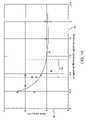
- FIG. 14is a graphical representation of data taken from kink simulation testing of model grafts having a plurality of circumferential inflatable channels with varied longitudinal spacing and varied longitudinal thickness.
- the “Y” axisrepresents the minimum bend radius for a given model graft configuration and the “X” axis represents the ratio of the longitudinal thickness of the circumferential inflatable channels of the model graft to the longitudinal spacing of the circumferential inflatable channels of the model graft.
- FIG. 15shows a portion of an endovascular graft having a plurality of circumferential inflatable channels.
- the circumferential inflatable channelsare disposed in three different longitudinal sections wherein the longitudinal spacing of the circumferential inflatable channels in each longitudinal section has a predetermined value that may be chosen to match a bend radius of a patient's intracorporeal conduit.
- FIGS. 1 and 2schematically show an embodiment of an endovascular graft assembly 5 .
- the endovascular graft assembly 5has a graft body section 8 having a generally tubular configuration with a proximal portion 6 , a distal portion 7 , and circumferential radial support members in the form of circumferential inflatable channels 11 disposed on body section 8 and shown in an expanded state.
- the circumferential inflatable channels 11are integrally formed in the body section 8 by seams 10 formed in the body section 8 .
- a longitudinal inflatable channel 16communicates with the circumferential inflatable channels 11 .
- a proximal connector member 12may be embedded within multiple layers of graft body section 8 in the vicinity of graft body section proximal portion 6 .
- a distal connector member 14may also be embedded within multiple layers of graft body section 8 in the vicinity of graft body section distal portion 7 .
- One or more expandable members or stentsmay be coupled or affixed to either or both proximal connector member 12 and distal connector member 14 via one or more connector member connector elements 17 .
- Such expandable members or stentsmay serve to anchor the endovascular graft 5 within a body lumen such as a blood vessel and resist longitudinal or axial forces imposed on the endovascular graft 5 by the pressure and flow of fluids through the graft 5 .
- connector elements 17 of the proximal and distal connector members 12 and 14extend longitudinally outside proximal portion 6 and distal portion 7 of endovascular graft assembly 5 , respectively.
- the circumferential inflatable channels 11provide radial structural support to the tubular section or configuration of the body section 8 .
- the circumferential inflatable channelsmay be filled on deployment of the graft with a variety of materials, including biocompatible fluids, such as saline or the like, or gels or fluids which are transmutable to a solid or semi-solid configuration.
- FIG. 2illustrates a transverse cross sectional view of a circular inflatable channel 11 and longitudinal inflatable channel 16 of the graft assembly 5 .
- Circular inflatable channel 11generally has an annular configuration.
- junction 18between the distal portion 7 of graft assembly 5 and a distal portion 21 of graft assembly main body portion 22 .
- junction 23between the proximal portion 6 of graft assembly 5 and a proximal portion 24 of graft assembly main body portion 22 .
- Junctions 18 and 23may be tapered and also may have overlapping portions. Such junctions 18 and 23 may be secured by sintering or thermomechanical compaction of the flexible material of the junctions 18 and 23 if the flexible material used is a fusible material that may be secured to itself by processes such as seam formation with a heated stylus.
- An important function of inflatable channels, such as circumferential inflatable channels 11 , in an endovascular graftmay be to provide some kink resistance to the graft body section 8 .
- Kink resistance of a tubular graft or portion or section thereof having circumferential inflatable channels 11is generally a function of the inflation pressure of the circumferential inflatable channels 11 , the longitudinal thickness of the inflatable channels 11 , and the longitudinal spacing of the circumferential inflatable channels 11 .
- Kinking in a vascular graft 5 or other tubular intracorporeal device or portion or section thereofgenerally occurs because the graft 5 is subjected to longitudinal compression, bending, or some combination thereof. There are many specific situations that may cause kinking. We have performed several studies to evaluate the relative effects of design parameters of endovascular grafts 5 and portions or sections thereof on kink resistance as described below.
- the geometry of a model graft 30 included in a kink simulation experimentis shown in FIG. 3 .
- the model graft 30includes a tubular section 31 and a helical inflatable channel 32 , but does not include a proximal or distal inflatable cuff (each of which may have a large longitudinal thickness relative to that of the helical inflatable channel 32 since these components are not expected to play a significant role in kink resistance of the model graft 30 ).
- a small initial curvature in the shape of a half-sine wavehas been incorporated into the model graft 30 .
- the amplitude of the sine waveis nominally set at one percent of a transverse dimension of the model graft 30 . This is a reasonable starting point for the simulation experiment as many if not all in vivo endovascular grafts typically will have some amount of longitudinal curvature imposed on them, depending on the indication for which they are used.
- Proximal and distal rigid cylinders 33 and 34are respectively attached to the proximal end 35 and distal end 36 of the model graft 30 as part of the simulation model.
- the distal rigid cylinder 34is fixed in all degrees of freedom for the purposes of the simulation experiment, and the proximal rigid cylinder 33 is restrained from all translation and rotation except axial motion.
- An axial compression motion at a constant rateis prescribed for the proximal rigid cylinder 33 to introduce compression and buckling into the model graft 30 .
- Single-surface contactis defined for the entire model graft 30 and outer surfaces of the helical inflatable channel 32 to properly model folding and prevent interpenetration of the model graft 30 surfaces during the simulation process.
- an isotropic linear elastic material modelwas used to represent the mechanical behavior of graft 30 material.
- the material parameters used in this studywere derived from a set of uniaxial tensile tests conducted by Vorp et al. at the University of Pittsburgh. The parameters obtained from these tests in two directions or orientations relative to fibril orientation of the ePTFE material were averaged and include an elastic modulus (E) of about 3.9 ksi and a Poisson's Ratio ( ⁇ ) of about 0.05. A material thickness of 0.0078 in.
- FIG. 4a longitudinal portion of the model graft 30 of FIG. 3 is shown in section. Outer layers of flexible material 37 are wrapped about inner layers of flexible material 38 with the helical inflatable channel 32 formed between the outer layers and inner layers 37 and 38 . Various dimensions relating to the tubular section 31 and helical inflatable channel 32 are illustrated.
- An outer transverse dimension or diameter of the tubular section 31 of the model graft 30is indicated by arrowed line 39 and refers to the outer transverse dimension or diameter of the outer layers of the flexible material 37 of the tubular section 31 of the model graft 30 disposed between the coils 40 of the helical inflatable channel 32 .
- the pitch of the helical inflatable channel 32is indicated by arrowed line 41 and refers to the nominal dimension of the distance from a longitudinal center 42 of a coil of the helical inflatable channel 32 to a longitudinal center 45 of an adjacent coil of the helical inflatable channel 32 .
- a longitudinal spacing of adjacent coils of the helical inflatable channel 32is indicated by arrowed line 46 and indicates the minimum longitudinal distance from the outer layers of flexible material 37 of a coil of the helical inflatable channel 32 to the outer layers of flexible material 37 of a longitudinally adjacent coil of the helical inflatable channel 32 .
- a longitudinal thickness of the helical inflatable channel 32is indicated by arrowed line 47 and a radial thickness of the helical inflatable channel is indicated by arrowed line 48 .
- the longitudinal thickness of the helical inflatable channel 32is the maximum longitudinal distance from the outer layer of flexible material 37 of a segment 51 of the helical inflatable channel 32 on one side of the helical inflatable channel 32 to the outer layers of flexible material 37 on the opposite side of the helical inflatable channel 32 .
- the radial thickness 48 of the helical inflatable channel 32is similarly defined in a radial direction from the outer layers of flexible material 37 to the inner layers of flexible material 38 of a segment 52 of the helical inflatable channel 32 .
- a first segment 53 of the helical inflatable channel 32is shown disposed longitudinally adjacent an adjacent second segment 54 of the helical inflatable channel 32 .
- the kink resistance simulation testingis performed as follows. First, hemodynamic pressure loads on the interior surface 55 of the model graft 30 and channel pressure loads on the interior surface 56 of the helical inflatable channel 32 are increased from zero to the predetermined values. A hemodynamic pressure of 120 mm Hg inside the tubular section 31 of the model graft 30 was used for all simulations. Once both pressure loads were up to their full predetermined values and the model graft 30 stabilized, then the proximal rigid cylinder 33 was given a prescribed inward axial motion to induce compression and buckling in the model graft 30 . The simulation was performed using TriVascular, Inc.'s version of DYNA3D, an explicit nonlinear finite element code. These model graft 30 kink simulations were performed as transient dynamic analyses, with the loads applied sufficiently slowly that essentially quasistatic results were obtained.
- model graft 30was a particular simulation study was conducted for the model graft 30 as shown in FIG. 3 .
- the model graft 30 parameterswere: model graft 30 length of 4.0 in. (101.6 mm), model graft 30 lumen diameter of 0.87 in. (22.1 mm), helical inflatable channel 32 longitudinal thickness or diameter, 20 percent of model graft 30 lumen diameter, helical inflatable channel 32 pitch of 0.4 in. (10.2 mm), tubular section lumen hemodynamic pressure of 2.32 psi (120 mm Hg), and model graft 30 wall thickness of outer layers of flexible material 37 and inner layers of flexible material 38 of 0.006 in. (0.15 mm) outside the channels and 0.003 in. (0.08 mm) for the helical inflatable channel walls.
- FIG. 5illustrates a model graft 60 having a plurality of circumferential inflatable channels 61 disposed on a tubular section 62 of the model graft 60 .
- the model graft 60includes the tubular section 62 and a plurality of circumferential inflatable channels 61 , but does not include a proximal or distal inflatable cuff (each of which may have a large longitudinal thickness relative to that of the circumferential inflatable channels 61 since these components are not expected to play a significant role in kink resistance of the model graft 60 ).
- Proximal and distal rigid cylinders 63 and 64are respectively attached to the proximal end 65 and distal end 66 of the model graft 60 as part of the simulation model.
- the distal rigid cylinder 64is fixed in all degrees of freedom for the purposes of the simulation experiment, and the proximal rigid cylinder 63 is restrained from all translation and rotation except axial motion.
- An axial compression motion at a constant rateis prescribed for the proximal rigid cylinder 63 to introduce compression and buckling into the model graft 60 .
- Single-surface contactis defined for the entire model graft 60 and outer surfaces 67 of the circumferential inflatable channels 61 to properly model folding and prevent interpenetration of the model graft 60 surfaces during the simulation process.
- the design parameterssuch as model graft 60 length, tubular section 62 lumen diameter, circumferential inflatable channel 61 longitudinal thickness and longitudinal spacing of the circumferential inflatable channels 61 were the same as the corresponding parameters of the model graft 30 discussed above and shown in FIG. 3 .
- FIG. 6a longitudinal portion of the model graft 60 of FIG. 5 is shown in section. Outer layers of flexible material 70 are shown wrapped about inner layers of flexible material 71 with the plurality of circumferential inflatable channels 61 formed between the outer layers 70 and inner layers 71 . Various dimensions relating to the tubular section 62 and circumferential inflatable channels 61 are illustrated.
- the outer transverse dimension of the tubular section 62 of the model graft 60is indicated by arrowed line 72 and refers to the outer transverse dimension or diameter of the outer layers of the flexible material 70 of the tubular section 62 of the model graft 60 disposed between the circumferential inflatable channels 61 .
- the longitudinal spacing of the circumferential inflatable channels 61is indicated by arrowed line 73 and indicates the minimum longitudinal distance from the outer layers of flexible material 70 of a first circumferential inflatable channel 74 to the outer layers of flexible material 70 of a longitudinally adjacent circumferential inflatable channel 75 .
- the longitudinal thickness of the first circumferential inflatable channel 74is indicated by arrowed line 76 and the radial thickness of the longitudinally adjacent circumferential inflatable channel 75 is indicated by arrowed line 77 .
- the longitudinal thickness of the first circumferential inflatable channel 74is the maximum longitudinal distance from the outer layer of flexible material 70 of a segment of the first circumferential inflatable channel 74 on one side of the first circumferential inflatable channel 74 to the outer layers of flexible material 70 on the opposite side of the circumferential inflatable channel 74 .
- the radial thickness 77 of the adjacent circumferential inflatable channel 75is similarly defined in a radial direction from the outer layers of flexible material 70 to the inner layers of flexible material 71 of a segment of the adjacent circumferential inflatable channel 75 .
- a segment 78 of the first circumferential inflatable channel 74is shown disposed longitudinally adjacent a segment 79 of a second circumferential inflatable channel 75 .
- Model graft 60 behavior at a 0.1 psi inflation pressureproduced results comparable to an essentially unsupported endovascular graft.
- the predicted kink behavior for inflation pressures of 3, 10, and 25 psiwere tested.
- the helical and circumferential channels 32 and 61have little structural stability and collapse soon after coming into contact and going into compression as shown in the kinking sequence of FIGS. 7–10 , wherein the model graft 60 of FIGS. 5 and 6 is subjected to a force and eventually kinks as shown in FIGS. 9 and 10 .
- Low inflation pressuresresult in collapse of adjacent circumferential inflatable channels 61 after they come into contact on the inner radius of a model graft 60 subjected to bending. Collapse of circumferential inflatable channel 61 often results in the development of a kink at the location under contained compression, bending or both compression and bending.
- the circumferential channels 61act as essentially rigid reinforcement structures, carrying the compressive load on the inner surface 80 of the bend of the model graft 60 without significant deformation.
- This high inflation pressure caseis similar to the proposed inflation of the model graft 60 with an incompressible gel or liquid polymer that cross links to form a solid or semi-solid material.
- the length of model graft 60was held constant and the number of circumferential inflatable channels 61 was increased and varied.
- the longitudinal spacing between the circumferential inflatable channelswas adjusted to maintain the original length of the model graft 60 .
- a column compression/buckling analysiswas conducted to observe the model graft buckling behavior and kink development.
- each end of the model graft 60was attached to rigid cylinders 63 and 64 as shown in FIG. 5 .
- the cylinder motionwas then prescribed to compress the model graft 60 with ends 65 and 66 of the model graft 60 left free to rotate. This provides a qualitative check on the graft behavior in compression loading.
- the second type of analysiswas conducted by rotating each end 65 and 66 of the model graft 60 about a local axis to determine a minimum kink or bend radius for the model graft 60 .
- the rigid cylinders 63 and 64 at the ends of the model graft 60are given a prescribed rotation while they are also allowed to translate axially.
- the model graft 60forms a circular arc until a “critical” kink radius is achieved; i.e., a kink has initiated in the model graft 60 .
- This approachallows for a quantitative assessment of the design parameters.
- a dynamic relaxation methodwas used to impose an internal pressure loading of the model graft 60 , followed by a transient dynamic simulation that either compressed or rotated the ends 65 and 66 of the model graft 60 .
- the internal pressure of the circumferential inflatable channels 61was specified to simulate a solid fill material. It was assumed that the gel within the circumferential inflatable channels 61 of the model graft 60 was “incompressible” and possessed a very low shear strength.
- the inflation gelwas modeled using an isotropic-elastic-plastic material model with a low shear modulus (10 psi) and yield stress (10 psi), and a bulk modulus similar to that of water (500,000 psi).
- model graft 60 parameters used for this studywere: model graft 60 length of 3.87 in. (98.30 mm), model graft 60 diameter of 0.39 in. (9.91 mm), lumen hemodynamic pressure 2.32 psi (120 mm Hg), and model graft 60 wall thickness of 0.006 in. (0.15 mm) between the circumferential inflatable channels 61 and 0.003 in. (0.08 mm) for the circumferential inflatable channel 61 walls.
- the number of circumferential inflatable channels 61was varied from 14 to 21 (3.6 channels/in. to 5.4 channels/in.), while the longitudinal thickness or diameter of the circumferential inflatable channels 61 was varied from 0.080 to 0.126 in. (2.03 to 3.20 mm).
- a small initial curvaturewas introduced into the model graft 60 ; a half-sine wave shape with an amplitude of one percent of the model graft 60 length was used to provide some initial perturbation from a perfectly straight tubular section 62 .
- Kink resistance simulation testingwas then performed on the various configurations of model graft 60 .
- small circumferential inflatable channels 61having a longitudinal thickness of about 0.08 in. (2.03 mm) were positioned on the tubular section 62 of the model graft 60 with a longitudinal spacing of about 0.212 in. (5.38 mm). These parameters give a longitudinal channel thickness to longitudinal spacing ratio of about 0.38.
- Another way to state thisis that the longitudinal thickness of the circumferential inflatable channels 61 is about 38 percent of the longitudinal spacing of the circumferential inflatable channels 61 with the channels 61 in an inflated state.
- a transverse section of the circumferential inflatable channels 61 taken along a longitudinal axis 82 of the model graft 60has a substantially circular configuration such that the longitudinal thickness of the circumferential inflatable channels 61 is substantially the same as a radial thickness of the circumferential inflatable channels 61 .
- the model graft 60 testedhad circumferential inflatable channels 61 with a longitudinal thickness and radial thickness of about 0.126 in. (3.20 mm).
- the circumferential inflatable channels 61had a longitudinal spacing of about 0.162 in. (4.11 mm). This resulted in a longitudinal channel thickness to spacing ratio of about 78 percent.
- the longitudinal spacing of the circumferential inflatable channels 61 of model graft 60was further decreased to evaluate the effect of more closely spaced circumferential inflatable channels 61 on kink resistance.
- the ratio of longitudinal channel thickness to longitudinal spacingwas varied from about 50 to about 200 percent.
- the kink resistance of the model graft 60 with reduced longitudinal spacingshows significant improvement over the relatively large longitudinal spacing cases discussed above in the first and second simulation tests, as the circumferential inflatable channels 61 provide some resistance to the collapsing of the column and the folding of material between the circumferential inflatable channels 61 .
- our simulationsestimated a minimum model graft 60 bend radius of about 4 to about 5 mm for spacing ratios from about 125 to about 200 percent as will be described later in conjunction with FIG. 14 .
- FIGS. 11–13The effect of reducing longitudinal spacing 73 of the circumferential inflatable channels 61 in model graft 60 during such a simulation test may be seen in the exemplary illustrated sequence of FIGS. 11–13 (dimensions are not included to illustrate the general principle).
- a model graft 60 having a relatively small longitudinal spacing 73 between the circumferential inflatable channels 61is subjected to deflections in a simulation test and the tubular section begins to deform as shown in FIGS. 11–12 .
- the lumen of the tubular sectionremains patent even though the tubular section has been subjected to a small bend radius R shown in FIG. 13 .
- the axial length of the tubular section of the model graft 60 between the circumferential inflatable channels 61 of the model graft 60has started to approach the longitudinal thickness of the circumferential inflatable channels 61 ; stated another way, the longitudinal channel thickness to spacing ratio approaches about 1.0.
- the resulting configurationprovides resistance to slippage of circumferential inflatable channels 61 under adjacent circumferential inflatable channels 61 as the model graft 60 is compressed.
- a reduced longitudinal spacingallows the inflatable channels 61 to come into contact with nearly normal contact forces rather than the largely oblique contact forces which arise when the kink is more developed before circumferential inflatable channel 61 contact one another, such as occurs with increased longitudinal spacing.
- FIG. 14is a graphical representation of the results of several simulation tests such as those discussed above.
- the datarepresent the minimum bend radius that may be achieved for a model graft 60 without kinking plotted as a function of the ratio of longitudinal thickness of the model graft circumferential inflatable channels 61 to the longitudinal spacing for channels 61 that have a longitudinal or radial thickness of about 8.5 to about 32 percent of the outer transverse dimension or diameter of the model graft tubular section.
- the simulation test data represented in FIG. 14include results from varied diameters of tubular section 62 of from about 10 mm to about 22.1 mm. It is generally desirable to reduce the number of circumferential inflatable channels 61 while improving the kink resistance of an endovascular graft or portion or section thereof, such as the endovascular graft 5 shown in FIG. 1 having circumferential inflatable channels 11 .
- a longitudinal spacing of circumferential inflatable channels 61may cause a variety of difficulties with regard to the manufacture, deployment and function of an endovascular graft 5 having these features.
- unacceptably close longitudinal spacing 73 of circumferential inflatable channels 61results in a large number of channels 61 that require a greater number of seams 10 to be formed in the tubular section 62 .
- Increasing the number of circumferential inflatable channels 61results in a greater internal inflatable volume of the circumferential inflatable channels 61 which must be filled with a fill fluid liquid, gel or gas upon deployment. This results in a greater amount of fill fluid used and greater amount of time required to fill the volume during deployment of the endovascular graft 5 .
- a large number of closely spaced circumferential inflatable channels 61may cause a significant amount of axial contraction of the graft 5 as the circumferential inflatable channels 61 transition from a flat uninflated state to an inflated state where the longitudinal cross section has, for example, a substantially circular configuration.
- Significant axial contraction during deploymentmay create difficulties for the clinician deploying the graft 5 , particularly with regard to properly sizing the graft for the patient's anatomy.
- Axial conformity or compressibilitymay also degrade with decreased longitudinal spacing between the circumferential inflatable channels 61 .
- the “Y” axis 90represents the minimum bend radius for a given model graft 60 configuration.
- the “X” axis 91represents the ratio of the longitudinal thickness 76 of the circumferential inflatable channels 61 of the model graft 60 to the longitudinal spacing 73 of the circumferential inflatable channels 61 of the model graft 60 .
- a longitudinal thickness of the circumferential inflatable channels 61 that is substantially equal to their longitudinal spacingi.e. a ratio approaching about 1.0
- Clinical evaluationshave shown this to be a desirable target for minimum bend radius given likely patient morphology for aortic aneurysms and the like.
- channel thickness/spacing ratiosof from about 0.5 and about 2.0, and more preferably from about 0.7 and about 1.1, yield these minimum bend radius parameters while also providing for acceptable manufacturability and axial compression behavior for endovascular grafts such as graft 5 of FIG. 1 as shown by the bracketed region 92 in FIG. 14 .
- the thickness/spacing ratios illustrated in FIG. 14 and described in relation to FIGS. 11–13are equally applicable to the grafts of FIGS. 3 and 4 that have a helical inflatable channel.
- the ideal longitudinal thickness 76 of the circumferential inflatable channels 61 in an endovascular graft 5 or portion or section thereofshould be from about 50 to about 200 percent of a longitudinal spacing 73 of the circumferential inflatable channels 61 (corresponding to a minimum bend radius of approximately 10 mm); more preferably from about 70 to about 110 percent (corresponding to a minimum bend radius of between about 5 and about 7 mm) for an endovascular graft with circumferential inflatable channels 61 that have a longitudinal or radial thickness that are about 8.5 to about 32 percent of the outer transverse dimension or diameter of the tubular section 62 of the model graft 60 .
- FIG. 15shows a portion of a model graft 96 having a tubular section 97 with a plurality of circumferential inflatable channels 98 disposed on the tubular section 97 .
- the circumferential inflatable channels 98are disposed in three different longitudinal sections wherein the longitudinal spacing of the circumferential inflatable channels 98 in each longitudinal section has a predetermined value.
- the longitudinal spacing of the circumferential inflatable channels 98may be chosen to substantially match a bend radius of a patient's intracorporeal conduit (not shown).
- a first longitudinal section 99 indicated by arrowed line 100is disposed at a first end 101 of the model graft 96 and has a plurality of circumferential inflatable channels 102 with a substantially constant longitudinal spacing.
- a second longitudinal section 104 indicated by arrowed line 105has a plurality of circumferential inflatable channels 106 having a substantially constant longitudinal spacing that is less than the longitudinal spacing of the circumferential inflatable channels 102 of the first longitudinal section 99 of model graft 96 .
- the second longitudinal section 104is disposed axially adjacent the first longitudinal section 99 of the model graft 96 .
- a third longitudinal section 108 indicated by arrowed line 109is disposed axially adjacent the second longitudinal section 104 .
- the third longitudinal section 108has a plurality of circumferential inflatable channels 110 having a substantially constant longitudinal spacing that is greater than the longitudinal spacing of the circumferential inflatable channels 106 of the second longitudinal section 104 of the model graft 96 .
- an endovascular graftmay have a tubular section 97 with first longitudinal section 99 with a plurality of circumferential inflatable channels 102 with a substantially constant longitudinal spacing that is about 50 to about 75 percent of a longitudinal thickness of the circumferential inflatable channels 102 in the first longitudinal section 99 in an inflated state.
- the tubular section 97also has a second longitudinal section 104 with a plurality of circumferential inflatable channels 106 with a substantially constant longitudinal spacing that is about 100 to about 200 percent of a longitudinal thickness of the circumferential inflatable channels 106 of the second longitudinal section 104 in an inflated state.
- the first longitudinal section 99 and second longitudinal section 104may be axially adjacent each other.
- the first longitudinal section 99is configured to accommodate a conduit of a patient's anatomy that has a small bend radius down to about 8 mm.
- the second longitudinal section 104is configured to accommodate a conduit of a patient's anatomy that has a bend radius of about 5 mm.
- an endovascular graftmay have a tubular section 97 with a first longitudinal section 102 with a helical inflatable channel (such as the helical inflatable channel 32 shown in FIGS. 3 and 4 ) with a substantially constant longitudinal spacing between adjacent coils 40 that is about 50 to about 75 percent of a longitudinal thickness of the helical inflatable channel 32 with the helical inflatable channel 32 in an inflated state.
- the tubular section 97has a second longitudinal section 104 with a helical inflatable channel 32 with a substantially constant longitudinal spacing between adjacent coils 40 with the helical inflatable channel 32 in an inflated state.
- the longitudinal spacing of the coils 40 of the second longitudinal section 104may be about 100 to about 200 percent of a longitudinal thickness of the helical inflatable channel 32 of the second longitudinal section 99 in an inflated state.
Landscapes
- Health & Medical Sciences (AREA)
- Gastroenterology & Hepatology (AREA)
- Pulmonology (AREA)
- Cardiology (AREA)
- Oral & Maxillofacial Surgery (AREA)
- Transplantation (AREA)
- Engineering & Computer Science (AREA)
- Biomedical Technology (AREA)
- Heart & Thoracic Surgery (AREA)
- Vascular Medicine (AREA)
- Life Sciences & Earth Sciences (AREA)
- Animal Behavior & Ethology (AREA)
- General Health & Medical Sciences (AREA)
- Public Health (AREA)
- Veterinary Medicine (AREA)
- Prostheses (AREA)
- Media Introduction/Drainage Providing Device (AREA)
Abstract
Description
Claims (41)
Priority Applications (8)
| Application Number | Priority Date | Filing Date | Title |
|---|---|---|---|
| US10/384,103US7150758B2 (en) | 2003-03-06 | 2003-03-06 | Kink resistant endovascular graft |
| EP10183146.9AEP2319456B1 (en) | 2003-03-06 | 2004-03-05 | Kink resistant endovascular graft |
| AU2004220616AAU2004220616C1 (en) | 2003-03-06 | 2004-03-05 | Kink resistant endovascular graft |
| EP04718097AEP1601314B1 (en) | 2003-03-06 | 2004-03-05 | Kink resistant endovascular graft |
| AT04718097TATE535211T1 (en) | 2003-03-06 | 2004-03-05 | KINK-RESISTANT ENDOVASCULAR IMPLANT |
| JP2006509190AJP2006519682A (en) | 2003-03-06 | 2004-03-05 | Twist-resistant intravascular graft |
| PCT/US2004/006843WO2004080338A2 (en) | 2003-03-06 | 2004-03-05 | Kink resistant endovascular graft |
| CA2518099ACA2518099C (en) | 2003-03-06 | 2004-03-05 | Kink resistant endovascular graft |
Applications Claiming Priority (1)
| Application Number | Priority Date | Filing Date | Title |
|---|---|---|---|
| US10/384,103US7150758B2 (en) | 2003-03-06 | 2003-03-06 | Kink resistant endovascular graft |
Publications (2)
| Publication Number | Publication Date |
|---|---|
| US20040176836A1 US20040176836A1 (en) | 2004-09-09 |
| US7150758B2true US7150758B2 (en) | 2006-12-19 |
Family
ID=32927194
Family Applications (1)
| Application Number | Title | Priority Date | Filing Date |
|---|---|---|---|
| US10/384,103Expired - LifetimeUS7150758B2 (en) | 2003-03-06 | 2003-03-06 | Kink resistant endovascular graft |
Country Status (7)
| Country | Link |
|---|---|
| US (1) | US7150758B2 (en) |
| EP (2) | EP2319456B1 (en) |
| JP (1) | JP2006519682A (en) |
| AT (1) | ATE535211T1 (en) |
| AU (1) | AU2004220616C1 (en) |
| CA (1) | CA2518099C (en) |
| WO (1) | WO2004080338A2 (en) |
Cited By (43)
| Publication number | Priority date | Publication date | Assignee | Title |
|---|---|---|---|---|
| US20090099642A1 (en)* | 2007-10-10 | 2009-04-16 | C.R. Bard, Inc. | Kink resistant stent graft |
| US20100010502A1 (en)* | 2008-07-10 | 2010-01-14 | Sumit Verma | Endovascular conduit device for increasing safety of cardiac lead extraction and other vascular procedures |
| US20110082465A1 (en)* | 2008-07-10 | 2011-04-07 | Atrial Systems, Llc | Endovascular conduit device with low profile occlusion members |
| US8012201B2 (en) | 2004-05-05 | 2011-09-06 | Direct Flow Medical, Inc. | Translumenally implantable heart valve with multiple chamber formed in place support |
| US20110288628A1 (en)* | 2010-05-20 | 2011-11-24 | Maquet Cardiovascular LLC. | Composite prosthesis with external polymeric support structure and methods of manufacturing the same |
| US8066755B2 (en) | 2007-09-26 | 2011-11-29 | Trivascular, Inc. | System and method of pivoted stent deployment |
| US8083789B2 (en) | 2007-11-16 | 2011-12-27 | Trivascular, Inc. | Securement assembly and method for expandable endovascular device |
| US20120165857A1 (en)* | 2004-02-17 | 2012-06-28 | Boston Scientific Scimed, Inc., | Endoscopic tissue stabilization device and related methods of use |
| US8226701B2 (en) | 2007-09-26 | 2012-07-24 | Trivascular, Inc. | Stent and delivery system for deployment thereof |
| US8241346B2 (en) | 2001-12-20 | 2012-08-14 | Trivascular, Inc. | Endovascular graft and method of delivery |
| US8328861B2 (en) | 2007-11-16 | 2012-12-11 | Trivascular, Inc. | Delivery system and method for bifurcated graft |
| WO2013151794A2 (en) | 2012-04-03 | 2013-10-10 | Trivascular, Inc. | Advanced kink-resistant stent graft |
| US8556881B2 (en) | 2006-10-19 | 2013-10-15 | Direct Flow Medical, Inc. | Catheter guidance through a calcified aortic valve |
| US8568477B2 (en) | 2005-06-07 | 2013-10-29 | Direct Flow Medical, Inc. | Stentless aortic valve replacement with high radial strength |
| WO2013188134A1 (en) | 2012-06-15 | 2013-12-19 | Trivascular, Inc. | Bifurcated endovascular prosthesis having tethered contralateral leg |
| WO2013188132A1 (en) | 2012-06-15 | 2013-12-19 | Trivascular, Inc. | Endovascular delivery system with an improved radiopaque marker scheme |
| WO2013188133A1 (en) | 2012-06-15 | 2013-12-19 | Trivascular, Inc. | Endovascular delivery system with flexible and torqueable hypotube |
| US8663309B2 (en) | 2007-09-26 | 2014-03-04 | Trivascular, Inc. | Asymmetric stent apparatus and method |
| WO2014059114A2 (en) | 2012-10-10 | 2014-04-17 | Trivascular, Inc. | Endovascular graft for aneurysms involving major branch vessels |
| WO2014110254A1 (en) | 2013-01-10 | 2014-07-17 | Trivascular, Inc. | Gate wire for contralateral leg access |
| US20140243950A1 (en)* | 2013-02-28 | 2014-08-28 | Boston Scientific Scimed, Inc. | Stent with balloon for repair of anastomosis surgery leaks |
| US8992595B2 (en) | 2012-04-04 | 2015-03-31 | Trivascular, Inc. | Durable stent graft with tapered struts and stable delivery methods and devices |
| WO2015048004A1 (en) | 2013-09-24 | 2015-04-02 | Trivascular, Inc. | Tandem modular endograft |
| WO2015138402A1 (en) | 2014-03-10 | 2015-09-17 | Trivascular, Inc. | Inflatable occlusion wire-balloon for aortic applications |
| US9308301B2 (en) | 2005-04-01 | 2016-04-12 | Trivascular, Inc. | Non-degradable, low swelling, water soluble radiopaque hydrogel polymer |
| US9308360B2 (en) | 2007-08-23 | 2016-04-12 | Direct Flow Medical, Inc. | Translumenally implantable heart valve with formed in place support |
| US9433501B2 (en) | 2010-05-19 | 2016-09-06 | Direct Flow Medical, Inc. | Inflation media for implants |
| US9445897B2 (en) | 2012-05-01 | 2016-09-20 | Direct Flow Medical, Inc. | Prosthetic implant delivery device with introducer catheter |
| US9498363B2 (en) | 2012-04-06 | 2016-11-22 | Trivascular, Inc. | Delivery catheter for endovascular device |
| US9572661B2 (en) | 2006-10-19 | 2017-02-21 | Direct Flow Medical, Inc. | Profile reduction of valve implant |
| US9603708B2 (en) | 2010-05-19 | 2017-03-28 | Dfm, Llc | Low crossing profile delivery catheter for cardiovascular prosthetic implant |
| US9655754B2 (en) | 2013-01-10 | 2017-05-23 | Trivascular, Inc. | Systems and methods for guidewire crossover for bifurcated prostheses |
| US20170151051A1 (en)* | 2014-06-26 | 2017-06-01 | S&G Biotech, Inc. | Stent having exterior path |
| US20170348087A1 (en)* | 2001-12-20 | 2017-12-07 | Trivascular, Inc. | Advanced endovascular graft |
| US9956101B2 (en) | 2014-12-04 | 2018-05-01 | Trivascular, Inc. | Internal iliac preservation devices and methods |
| EP3409243A1 (en) | 2014-01-09 | 2018-12-05 | TriVascular, Inc. | Systems for guidewire crossover for bifurcated prostheses |
| US10159557B2 (en) | 2007-10-04 | 2018-12-25 | Trivascular, Inc. | Modular vascular graft for low profile percutaneous delivery |
| US10653510B2 (en) | 2016-11-09 | 2020-05-19 | Boston Scientific Scimed, Inc. | Stent including displacement capabilities |
| US10849774B2 (en) | 2014-10-23 | 2020-12-01 | Trivascular, Inc. | Stent graft delivery system with access conduit |
| US20210093448A1 (en)* | 2015-03-12 | 2021-04-01 | Cedars-Sinai Medical Center | Devices, systems, and methods to optimize annular orientation of transcatheter valves |
| US11786355B2 (en) | 2020-01-30 | 2023-10-17 | Boston Scientific Scimed, Inc. | Radial adjusting self-expanding stent with anti-migration features |
| US12016768B2 (en) | 2015-05-11 | 2024-06-25 | Trivascular, Inc. | Stent-graft with improved flexibility |
| US12427017B2 (en) | 2013-12-11 | 2025-09-30 | Cedars Sinai Medical Center | Methods, devices and systems for transcatheter mitral valve replacement in a double-orifice mitral valve |
Families Citing this family (21)
| Publication number | Priority date | Publication date | Assignee | Title |
|---|---|---|---|---|
| US7641686B2 (en) | 2004-04-23 | 2010-01-05 | Direct Flow Medical, Inc. | Percutaneous heart valve with stentless support |
| US7588596B2 (en)* | 2004-12-29 | 2009-09-15 | Scimed Life Systems, Inc. | Endoluminal prosthesis adapted to resist migration and method of deploying the same |
| US20060233991A1 (en) | 2005-04-13 | 2006-10-19 | Trivascular, Inc. | PTFE layers and methods of manufacturing |
| US8192477B2 (en)* | 2005-11-14 | 2012-06-05 | Boston Scientific Scimed, Inc. | Twisting bifurcation delivery system |
| US20080140182A1 (en)* | 2006-04-28 | 2008-06-12 | Patricia Scheller | Composite endoluminal prostheses for treating vulnerable plaque |
| US8216297B2 (en)* | 2006-08-14 | 2012-07-10 | Trivascular, Inc. | Dual chamber cuff structure |
| US8905961B2 (en)* | 2008-12-19 | 2014-12-09 | St. Jude Medical, Inc. | Systems, apparatuses, and methods for cardiovascular conduits and connectors |
| US20110218609A1 (en)* | 2010-02-10 | 2011-09-08 | Trivascular, Inc. | Fill tube manifold and delivery methods for endovascular graft |
| WO2011156176A1 (en) | 2010-06-08 | 2011-12-15 | Regents Of The University Of Minnesota | Vascular elastance |
| EP2640319B1 (en)* | 2010-11-16 | 2016-10-19 | TriVascular, Inc. | Advanced endovascular graft and delivery system |
| JP5782523B2 (en) | 2010-11-22 | 2015-09-24 | アリア シーブイ, インコーポレイテッド | System and method for reducing pulsating pressure |
| CA3113910C (en) | 2012-08-10 | 2023-09-19 | Abiomed, Inc. | Graft anchor devices, systems, and methods |
| US8876850B1 (en) | 2014-06-19 | 2014-11-04 | Aria Cv, Inc. | Systems and methods for treating pulmonary hypertension |
| US10137986B1 (en) | 2015-03-25 | 2018-11-27 | Amazon Technologies, Inc. | Airlift package protection airbag container |
| US9914539B1 (en) | 2015-03-25 | 2018-03-13 | Amazon Technologies, Inc. | Airlift package protection airbag |
| JP6803340B2 (en) | 2015-05-27 | 2020-12-23 | トリバスキュラー・インコーポレイテッドTriVascular, INC. | Balloon support intraluminal prosthesis deployment |
| JP7083249B2 (en) | 2015-07-30 | 2022-06-10 | トリバスキュラー・インコーポレイテッド | Intraluminal prosthesis deployment device and method |
| WO2018075552A1 (en) | 2016-10-19 | 2018-04-26 | Aria Cv, Inc. | Diffusion resistant implantable devices for reducing pulsatile pressure |
| GB2577052B (en) | 2018-09-11 | 2021-04-28 | Strait Access Tech Holdings Pty Ltd | Expandable sleeved stent and method of making such stent |
| WO2021046252A1 (en) | 2019-09-06 | 2021-03-11 | Aria Cv, Inc. | Diffusion and infusion resistant implantable devices for reducing pulsatile pressure |
| CN115955988A (en) | 2020-06-25 | 2023-04-11 | 阿里亚Cv 有限公司 | Implantable device for reducing pulsatile pressure within blood vessels |
Citations (53)
| Publication number | Priority date | Publication date | Assignee | Title |
|---|---|---|---|---|
| US3631854A (en) | 1969-05-19 | 1972-01-04 | Robert Howard Fryer | Inflatable medical assemblies |
| US3902198A (en) | 1974-05-20 | 1975-09-02 | Gore & Ass | Method of replacing a body part with expanded porous polytetrafluoroethylene |
| US3991767A (en) | 1973-11-02 | 1976-11-16 | Cutter Laboratories, Inc. | Tubular unit with vessel engaging cuff structure |
| US4183102A (en) | 1977-09-08 | 1980-01-15 | Jacques Guiset | Inflatable prosthetic device for lining a body duct |
| EP0441516A2 (en) | 1990-02-08 | 1991-08-14 | Howmedica Inc. | Inflatable stent |
| US5151105A (en) | 1991-10-07 | 1992-09-29 | Kwan Gett Clifford | Collapsible vessel sleeve implant |
| US5156620A (en) | 1991-02-04 | 1992-10-20 | Pigott John P | Intraluminal graft/stent and balloon catheter for insertion thereof |
| US5330528A (en) | 1989-12-01 | 1994-07-19 | British Technology Group Limited | Vascular surgical devices |
| EP0617930A1 (en) | 1993-03-22 | 1994-10-05 | Industrial Research B.V. | Expandable endovaskular stent |
| US5370691A (en) | 1993-01-26 | 1994-12-06 | Target Therapeutics, Inc. | Intravascular inflatable stent |
| US5411550A (en) | 1991-09-16 | 1995-05-02 | Atrium Medical Corporation | Implantable prosthetic device for the delivery of a bioactive material |
| US5534024A (en) | 1994-11-04 | 1996-07-09 | Aeroquip Corporation | Intraluminal stenting graft |
| US5554180A (en) | 1995-07-07 | 1996-09-10 | Aeroquip Corporation | Intraluminal stenting graft |
| US5556426A (en) | 1994-08-02 | 1996-09-17 | Meadox Medicals, Inc. | PTFE implantable tubular prostheses with external coil support |
| US5607478A (en) | 1996-03-14 | 1997-03-04 | Meadox Medicals Inc. | Yarn wrapped PTFE tubular prosthesis |
| US5609624A (en) | 1993-10-08 | 1997-03-11 | Impra, Inc. | Reinforced vascular graft and method of making same |
| US5665117A (en) | 1995-11-27 | 1997-09-09 | Rhodes; Valentine J. | Endovascular prosthesis with improved sealing means for aneurysmal arterial disease and method of use |
| US5709701A (en) | 1996-05-30 | 1998-01-20 | Parodi; Juan C. | Apparatus for implanting a prothesis within a body passageway |
| US5749880A (en) | 1995-03-10 | 1998-05-12 | Impra, Inc. | Endoluminal encapsulated stent and methods of manufacture and endoluminal delivery |
| WO1998055047A1 (en) | 1997-06-06 | 1998-12-10 | Samuels Shaun L W | Inflatable intraluminal stent and method for affixing same within the human body |
| WO1999000073A1 (en) | 1997-06-28 | 1999-01-07 | Anson Medical Limited | Expandable device |
| US5871537A (en) | 1996-02-13 | 1999-02-16 | Scimed Life Systems, Inc. | Endovascular apparatus |
| WO1999026559A1 (en) | 1997-11-25 | 1999-06-03 | Triad Vascular Systems, Inc. | Layered endovascular graft |
| WO1999032051A1 (en) | 1997-12-22 | 1999-07-01 | Impra, Inc. | Supported graft and methods of making same |
| WO1999039662A1 (en) | 1998-02-09 | 1999-08-12 | Triad Vascular Systems, Inc. | Endovascular graft |
| US5976179A (en) | 1993-08-20 | 1999-11-02 | Inoue; Kanji | Appliance collapsible for insertion into a human organ and capable of resilient restoration |
| US6042605A (en) | 1995-12-14 | 2000-03-28 | Gore Enterprose Holdings, Inc. | Kink resistant stent-graft |
| US6053943A (en) | 1995-12-08 | 2000-04-25 | Impra, Inc. | Endoluminal graft with integral structural support and method for making same |
| WO2000051522A1 (en) | 1999-03-03 | 2000-09-08 | Clifford Rowan Murch | Inflatable intraluminal graft |
| US6132457A (en) | 1997-10-22 | 2000-10-17 | Triad Vascular Systems, Inc. | Endovascular graft having longitudinally displaceable sections |
| US6143015A (en) | 1997-05-19 | 2000-11-07 | Cardio Medical Solutions, Inc. | Device and method for partially occluding blood vessels using flow-through balloon |
| WO2001021107A1 (en) | 1999-09-22 | 2001-03-29 | Impra, Inc. | Prosthesis for abdominal aortic aneurysm repair |
| US6235050B1 (en)* | 1994-05-12 | 2001-05-22 | Endovascular Technologies, Inc. | System and method for intraluminally deploying a bifurcated graft |
| US20010007955A1 (en) | 1999-05-03 | 2001-07-12 | Drasler William J. | Intravascular hinge stent |
| US6293968B1 (en) | 1999-09-02 | 2001-09-25 | Syde A. Taheri | Inflatable intraluminal vascular stent |
| WO2002029758A2 (en) | 2000-10-04 | 2002-04-11 | Trivascular, Inc. | Virtual prototyping and testing for medical device development |
| US6371979B1 (en)* | 1993-01-27 | 2002-04-16 | Intratherapeutics, Inc. | Stent delivery system |
| US6398803B1 (en) | 1999-02-02 | 2002-06-04 | Impra, Inc., A Subsidiary Of C.R. Bard, Inc. | Partial encapsulation of stents |
| US6416537B1 (en) | 1996-12-03 | 2002-07-09 | Atrium Medical Corporation | Multi-stage prosthesis |
| US20020099436A1 (en) | 1996-12-23 | 2002-07-25 | Troy Thornton | Kink-resistant bifurcated prosthesis |
| US20020151953A1 (en) | 2001-04-11 | 2002-10-17 | Trivascular, Inc. | Delivery system and method for bifurcated endovascular graft |
| US20020151956A1 (en) | 2001-04-11 | 2002-10-17 | Trivascular, Inc. | Delivery system and method for endovascular graft |
| US20020173836A1 (en) | 1995-11-07 | 2002-11-21 | Leonard Pinchuk | Method of preventing the dislodgment of a stent-graft |
| US6524334B1 (en) | 1995-11-21 | 2003-02-25 | Schneider (Usa) | Expandable stent-graft covered with expanded polytetrafluoroethylene |
| US20030040803A1 (en)* | 2001-08-23 | 2003-02-27 | Rioux Robert F. | Maintaining an open passageway through a body lumen |
| US20030074048A1 (en) | 2001-10-16 | 2003-04-17 | Scimed Life Systems, Inc. | Tubular prosthesis for external agent delivery |
| US20030074058A1 (en) | 2001-10-16 | 2003-04-17 | Scimed Life Systems, Inc. | Aortic artery aneurysm endovascular prosthesis |
| US20030093145A1 (en) | 2001-10-26 | 2003-05-15 | Cook Incorporated | Endoluminal graft |
| US20030120331A1 (en)* | 2001-12-20 | 2003-06-26 | Trivascular, Inc. | Advanced endovascular graft |
| US20030116260A1 (en) | 2001-12-20 | 2003-06-26 | Trivascular, Inc. | Method and apparatus for manufacturing an endovascular graft section |
| US20030125797A1 (en) | 2001-12-20 | 2003-07-03 | Trivascular, Inc. | Advanced endovascular graft |
| US6602280B2 (en) | 2000-02-02 | 2003-08-05 | Trivascular, Inc. | Delivery system and method for expandable intracorporeal device |
| US20050209580A1 (en)* | 2002-12-30 | 2005-09-22 | Scimed Life Systems, Inc. | Valve treatment catheter and methods |
Family Cites Families (10)
| Publication number | Priority date | Publication date | Assignee | Title |
|---|---|---|---|---|
| US2955901A (en) | 1956-07-25 | 1960-10-11 | Bayer Ag | Process for dyeing polyethylene terephthalates |
| US2958401A (en) | 1957-06-03 | 1960-11-01 | Neville R Emery | Hydraulic slack adjusting device |
| US2955701A (en) | 1957-11-12 | 1960-10-11 | Joe Lowe Corp | Tray for cooling and proofing bakery products |
| US2957001A (en) | 1957-11-27 | 1960-10-18 | Du Pont | Process for preparing fluorine-containing organic compounds |
| US4580568A (en) | 1984-10-01 | 1986-04-08 | Cook, Incorporated | Percutaneous endovascular stent and method for insertion thereof |
| NL1003178C2 (en)* | 1996-05-21 | 1997-11-25 | Cordis Europ | Tubular prosthesis made of curable material. |
| US6416270B1 (en)* | 2000-08-29 | 2002-07-09 | Compu Shop Services, Llc | Automated library kiosk |
| US6776604B1 (en) | 2001-12-20 | 2004-08-17 | Trivascular, Inc. | Method and apparatus for shape forming endovascular graft material |
| EP1465685B1 (en) | 2001-12-20 | 2010-03-17 | TriVascular2, Inc. | Method and apparatus for manufacturing an endovascular graft section |
| US7090693B1 (en) | 2001-12-20 | 2006-08-15 | Boston Scientific Santa Rosa Corp. | Endovascular graft joint and method for manufacture |
- 2003
- 2003-03-06USUS10/384,103patent/US7150758B2/ennot_activeExpired - Lifetime
- 2004
- 2004-03-05CACA2518099Apatent/CA2518099C/ennot_activeExpired - Fee Related
- 2004-03-05ATAT04718097Tpatent/ATE535211T1/enactive
- 2004-03-05AUAU2004220616Apatent/AU2004220616C1/ennot_activeCeased
- 2004-03-05EPEP10183146.9Apatent/EP2319456B1/ennot_activeExpired - Lifetime
- 2004-03-05WOPCT/US2004/006843patent/WO2004080338A2/enactiveApplication Filing
- 2004-03-05EPEP04718097Apatent/EP1601314B1/ennot_activeExpired - Lifetime
- 2004-03-05JPJP2006509190Apatent/JP2006519682A/ennot_activeWithdrawn
Patent Citations (67)
| Publication number | Priority date | Publication date | Assignee | Title |
|---|---|---|---|---|
| US3631854A (en) | 1969-05-19 | 1972-01-04 | Robert Howard Fryer | Inflatable medical assemblies |
| US3991767A (en) | 1973-11-02 | 1976-11-16 | Cutter Laboratories, Inc. | Tubular unit with vessel engaging cuff structure |
| US3902198A (en) | 1974-05-20 | 1975-09-02 | Gore & Ass | Method of replacing a body part with expanded porous polytetrafluoroethylene |
| US4183102A (en) | 1977-09-08 | 1980-01-15 | Jacques Guiset | Inflatable prosthetic device for lining a body duct |
| US5330528A (en) | 1989-12-01 | 1994-07-19 | British Technology Group Limited | Vascular surgical devices |
| EP0441516A2 (en) | 1990-02-08 | 1991-08-14 | Howmedica Inc. | Inflatable stent |
| US5156620A (en) | 1991-02-04 | 1992-10-20 | Pigott John P | Intraluminal graft/stent and balloon catheter for insertion thereof |
| US5411550A (en) | 1991-09-16 | 1995-05-02 | Atrium Medical Corporation | Implantable prosthetic device for the delivery of a bioactive material |
| US5151105A (en) | 1991-10-07 | 1992-09-29 | Kwan Gett Clifford | Collapsible vessel sleeve implant |
| US5370691A (en) | 1993-01-26 | 1994-12-06 | Target Therapeutics, Inc. | Intravascular inflatable stent |
| US6371979B1 (en)* | 1993-01-27 | 2002-04-16 | Intratherapeutics, Inc. | Stent delivery system |
| EP0617930A1 (en) | 1993-03-22 | 1994-10-05 | Industrial Research B.V. | Expandable endovaskular stent |
| US5529653A (en) | 1993-03-22 | 1996-06-25 | Industrial Research B.V. | Expandable hollow sleeve for the local support and/or reinforcement of a body vessel, and method for the fabrication thereof |
| US5976179A (en) | 1993-08-20 | 1999-11-02 | Inoue; Kanji | Appliance collapsible for insertion into a human organ and capable of resilient restoration |
| US5609624A (en) | 1993-10-08 | 1997-03-11 | Impra, Inc. | Reinforced vascular graft and method of making same |
| US6235050B1 (en)* | 1994-05-12 | 2001-05-22 | Endovascular Technologies, Inc. | System and method for intraluminally deploying a bifurcated graft |
| US5556426A (en) | 1994-08-02 | 1996-09-17 | Meadox Medicals, Inc. | PTFE implantable tubular prostheses with external coil support |
| US5534024A (en) | 1994-11-04 | 1996-07-09 | Aeroquip Corporation | Intraluminal stenting graft |
| US5607468A (en) | 1994-11-04 | 1997-03-04 | Aeroquip Corporation | Method of manufacturing an intraluminal stenting graft |
| US5749880A (en) | 1995-03-10 | 1998-05-12 | Impra, Inc. | Endoluminal encapsulated stent and methods of manufacture and endoluminal delivery |
| US5554180A (en) | 1995-07-07 | 1996-09-10 | Aeroquip Corporation | Intraluminal stenting graft |
| US20020173836A1 (en) | 1995-11-07 | 2002-11-21 | Leonard Pinchuk | Method of preventing the dislodgment of a stent-graft |
| US6524334B1 (en) | 1995-11-21 | 2003-02-25 | Schneider (Usa) | Expandable stent-graft covered with expanded polytetrafluoroethylene |
| US5665117A (en) | 1995-11-27 | 1997-09-09 | Rhodes; Valentine J. | Endovascular prosthesis with improved sealing means for aneurysmal arterial disease and method of use |
| US6053943A (en) | 1995-12-08 | 2000-04-25 | Impra, Inc. | Endoluminal graft with integral structural support and method for making same |
| US6042605A (en) | 1995-12-14 | 2000-03-28 | Gore Enterprose Holdings, Inc. | Kink resistant stent-graft |
| US20020002397A1 (en) | 1995-12-14 | 2002-01-03 | Martin Gerald Ray | Kink resistant stent-graft |
| US20010049550A1 (en) | 1995-12-14 | 2001-12-06 | Gerald Ray Martin | Method of making a kink resistant stent-graft |
| US6361637B2 (en) | 1995-12-14 | 2002-03-26 | Gore Enterprise Holdings, Inc. | Method of making a kink resistant stent-graft |
| US5871537A (en) | 1996-02-13 | 1999-02-16 | Scimed Life Systems, Inc. | Endovascular apparatus |
| US6059823A (en) | 1996-02-13 | 2000-05-09 | Scimed Life Systems, Inc. | Endovascular apparatus |
| US5607478A (en) | 1996-03-14 | 1997-03-04 | Meadox Medicals Inc. | Yarn wrapped PTFE tubular prosthesis |
| US5709701A (en) | 1996-05-30 | 1998-01-20 | Parodi; Juan C. | Apparatus for implanting a prothesis within a body passageway |
| US6416537B1 (en) | 1996-12-03 | 2002-07-09 | Atrium Medical Corporation | Multi-stage prosthesis |
| US20020099436A1 (en) | 1996-12-23 | 2002-07-25 | Troy Thornton | Kink-resistant bifurcated prosthesis |
| US20020165603A1 (en) | 1996-12-23 | 2002-11-07 | Troy Thornton | Kink-resistant bifurcated prosthesis |
| US6143015A (en) | 1997-05-19 | 2000-11-07 | Cardio Medical Solutions, Inc. | Device and method for partially occluding blood vessels using flow-through balloon |
| WO1998055047A1 (en) | 1997-06-06 | 1998-12-10 | Samuels Shaun L W | Inflatable intraluminal stent and method for affixing same within the human body |
| US6007575A (en) | 1997-06-06 | 1999-12-28 | Samuels; Shaun Laurence Wilkie | Inflatable intraluminal stent and method for affixing same within the human body |
| WO1999000073A1 (en) | 1997-06-28 | 1999-01-07 | Anson Medical Limited | Expandable device |
| US6132457A (en) | 1997-10-22 | 2000-10-17 | Triad Vascular Systems, Inc. | Endovascular graft having longitudinally displaceable sections |
| WO1999026559A1 (en) | 1997-11-25 | 1999-06-03 | Triad Vascular Systems, Inc. | Layered endovascular graft |
| US6331191B1 (en) | 1997-11-25 | 2001-12-18 | Trivascular Inc. | Layered endovascular graft |
| WO1999032051A1 (en) | 1997-12-22 | 1999-07-01 | Impra, Inc. | Supported graft and methods of making same |
| WO1999039662A1 (en) | 1998-02-09 | 1999-08-12 | Triad Vascular Systems, Inc. | Endovascular graft |
| US6395019B2 (en) | 1998-02-09 | 2002-05-28 | Trivascular, Inc. | Endovascular graft |
| US6398803B1 (en) | 1999-02-02 | 2002-06-04 | Impra, Inc., A Subsidiary Of C.R. Bard, Inc. | Partial encapsulation of stents |
| WO2000051522A1 (en) | 1999-03-03 | 2000-09-08 | Clifford Rowan Murch | Inflatable intraluminal graft |
| US20010007955A1 (en) | 1999-05-03 | 2001-07-12 | Drasler William J. | Intravascular hinge stent |
| US6293968B1 (en) | 1999-09-02 | 2001-09-25 | Syde A. Taheri | Inflatable intraluminal vascular stent |
| US6312462B1 (en)* | 1999-09-22 | 2001-11-06 | Impra, Inc. | Prosthesis for abdominal aortic aneurysm repair |
| WO2001021107A1 (en) | 1999-09-22 | 2001-03-29 | Impra, Inc. | Prosthesis for abdominal aortic aneurysm repair |
| US20030220681A1 (en) | 2000-02-02 | 2003-11-27 | Trivascular, Inc. | Delivery system and method for expandable intracorporeal device |
| US6602280B2 (en) | 2000-02-02 | 2003-08-05 | Trivascular, Inc. | Delivery system and method for expandable intracorporeal device |
| WO2002029758A2 (en) | 2000-10-04 | 2002-04-11 | Trivascular, Inc. | Virtual prototyping and testing for medical device development |
| US20020151956A1 (en) | 2001-04-11 | 2002-10-17 | Trivascular, Inc. | Delivery system and method for endovascular graft |
| US20030004560A1 (en) | 2001-04-11 | 2003-01-02 | Trivascular, Inc. | Delivery system and method for bifurcated graft |
| US20020151953A1 (en) | 2001-04-11 | 2002-10-17 | Trivascular, Inc. | Delivery system and method for bifurcated endovascular graft |
| US20030040803A1 (en)* | 2001-08-23 | 2003-02-27 | Rioux Robert F. | Maintaining an open passageway through a body lumen |
| US20030074048A1 (en) | 2001-10-16 | 2003-04-17 | Scimed Life Systems, Inc. | Tubular prosthesis for external agent delivery |
| US20030074058A1 (en) | 2001-10-16 | 2003-04-17 | Scimed Life Systems, Inc. | Aortic artery aneurysm endovascular prosthesis |
| US20030093145A1 (en) | 2001-10-26 | 2003-05-15 | Cook Incorporated | Endoluminal graft |
| US20030120331A1 (en)* | 2001-12-20 | 2003-06-26 | Trivascular, Inc. | Advanced endovascular graft |
| US20030116260A1 (en) | 2001-12-20 | 2003-06-26 | Trivascular, Inc. | Method and apparatus for manufacturing an endovascular graft section |
| US20030120338A1 (en)* | 2001-12-20 | 2003-06-26 | Chobotov Michael V. | Advanced endovascular graft |
| US20030125797A1 (en) | 2001-12-20 | 2003-07-03 | Trivascular, Inc. | Advanced endovascular graft |
| US20050209580A1 (en)* | 2002-12-30 | 2005-09-22 | Scimed Life Systems, Inc. | Valve treatment catheter and methods |
Non-Patent Citations (3)
| Title |
|---|
| Haimovitch et al., "Robust growth is forecast for endovascular repair of AAAs," The BBI Newsletter, 26(5):113-114 (May 2003). |
| Uflacker, R. and Robinson, J., "Endovascular treatment of abdominal aortic aneurysms: a review," Eur. Radial., 11:739-753 (2001). |
| US 6,413,270, 07/2002, Thornton et al. (withdrawn) |
Cited By (84)
| Publication number | Priority date | Publication date | Assignee | Title |
|---|---|---|---|---|
| US8241346B2 (en) | 2001-12-20 | 2012-08-14 | Trivascular, Inc. | Endovascular graft and method of delivery |
| US20170348087A1 (en)* | 2001-12-20 | 2017-12-07 | Trivascular, Inc. | Advanced endovascular graft |
| US11439497B2 (en) | 2001-12-20 | 2022-09-13 | Trivascular, Inc. | Advanced endovascular graft |
| US8864814B2 (en) | 2001-12-20 | 2014-10-21 | Trivascular, Inc. | Method of delivering advanced endovascular graft and system |
| US10470871B2 (en)* | 2001-12-20 | 2019-11-12 | Trivascular, Inc. | Advanced endovascular graft |
| US20120165857A1 (en)* | 2004-02-17 | 2012-06-28 | Boston Scientific Scimed, Inc., | Endoscopic tissue stabilization device and related methods of use |
| US9510941B2 (en) | 2004-05-05 | 2016-12-06 | Direct Flow Medical, Inc. | Method of treating a patient using a retrievable transcatheter prosthetic heart valve |
| US8308796B2 (en) | 2004-05-05 | 2012-11-13 | Direct Flow Medical, Inc. | Method of in situ formation of translumenally deployable heart valve support |
| US8012201B2 (en) | 2004-05-05 | 2011-09-06 | Direct Flow Medical, Inc. | Translumenally implantable heart valve with multiple chamber formed in place support |
| US8377118B2 (en) | 2004-05-05 | 2013-02-19 | Direct Flow Medical, Inc. | Unstented heart valve with formed in place support structure |
| US10449040B2 (en) | 2004-05-05 | 2019-10-22 | Speyside Medical, LLC | Method of treating a patient using a retrievable transcatheter prosthetic heart valve |
| US9308301B2 (en) | 2005-04-01 | 2016-04-12 | Trivascular, Inc. | Non-degradable, low swelling, water soluble radiopaque hydrogel polymer |
| US11298444B2 (en) | 2005-04-01 | 2022-04-12 | Trivascular, Inc. | Non-degradable, low swelling, water soluble radiopaque hydrogel polymer |
| US8568477B2 (en) | 2005-06-07 | 2013-10-29 | Direct Flow Medical, Inc. | Stentless aortic valve replacement with high radial strength |
| US9572661B2 (en) | 2006-10-19 | 2017-02-21 | Direct Flow Medical, Inc. | Profile reduction of valve implant |
| US8556881B2 (en) | 2006-10-19 | 2013-10-15 | Direct Flow Medical, Inc. | Catheter guidance through a calcified aortic valve |
| US9308360B2 (en) | 2007-08-23 | 2016-04-12 | Direct Flow Medical, Inc. | Translumenally implantable heart valve with formed in place support |
| US10130463B2 (en) | 2007-08-23 | 2018-11-20 | Dfm, Llc | Translumenally implantable heart valve with formed in place support |
| US8663309B2 (en) | 2007-09-26 | 2014-03-04 | Trivascular, Inc. | Asymmetric stent apparatus and method |
| US8066755B2 (en) | 2007-09-26 | 2011-11-29 | Trivascular, Inc. | System and method of pivoted stent deployment |
| US8226701B2 (en) | 2007-09-26 | 2012-07-24 | Trivascular, Inc. | Stent and delivery system for deployment thereof |
| US10682222B2 (en) | 2007-10-04 | 2020-06-16 | Trivascular, Inc. | Modular vascular graft for low profile percutaneous delivery |
| US10159557B2 (en) | 2007-10-04 | 2018-12-25 | Trivascular, Inc. | Modular vascular graft for low profile percutaneous delivery |
| US12016766B2 (en) | 2007-10-04 | 2024-06-25 | Trivascular, Inc. | Modular vascular graft for low profile percutaneous delivery |
| US10098772B2 (en) | 2007-10-10 | 2018-10-16 | C. R. Bard, Inc. | Kink resistant stent graft |
| WO2009049229A3 (en)* | 2007-10-10 | 2009-09-11 | C. R. Bard, Inc. | Kink resistant stent graft |
| US20090099642A1 (en)* | 2007-10-10 | 2009-04-16 | C.R. Bard, Inc. | Kink resistant stent graft |
| US8328861B2 (en) | 2007-11-16 | 2012-12-11 | Trivascular, Inc. | Delivery system and method for bifurcated graft |
| US8083789B2 (en) | 2007-11-16 | 2011-12-27 | Trivascular, Inc. | Securement assembly and method for expandable endovascular device |
| US20110082465A1 (en)* | 2008-07-10 | 2011-04-07 | Atrial Systems, Llc | Endovascular conduit device with low profile occlusion members |
| US8454679B2 (en) | 2008-07-10 | 2013-06-04 | Atrial Systems, Llc | Endovascular conduit device for increasing safety of cardiac lead extraction and other vascular procedures |
| US8454680B2 (en) | 2008-07-10 | 2013-06-04 | Atrial Systems, Llc | Endovascular conduit device with low profile occlusion members |
| US20100010502A1 (en)* | 2008-07-10 | 2010-01-14 | Sumit Verma | Endovascular conduit device for increasing safety of cardiac lead extraction and other vascular procedures |
| US9603708B2 (en) | 2010-05-19 | 2017-03-28 | Dfm, Llc | Low crossing profile delivery catheter for cardiovascular prosthetic implant |
| US9433501B2 (en) | 2010-05-19 | 2016-09-06 | Direct Flow Medical, Inc. | Inflation media for implants |
| US10478299B2 (en) | 2010-05-19 | 2019-11-19 | Dfm, Llc | Low crossing profile delivery catheter for cardiovascular prosthetic implant |
| US20110288628A1 (en)* | 2010-05-20 | 2011-11-24 | Maquet Cardiovascular LLC. | Composite prosthesis with external polymeric support structure and methods of manufacturing the same |
| US9375326B2 (en) | 2010-05-20 | 2016-06-28 | Maquet Cardiovascular Llc | Composite prosthesis with external polymeric support structure and methods of manufacturing the same |
| US8696738B2 (en)* | 2010-05-20 | 2014-04-15 | Maquet Cardiovascular Llc | Composite prosthesis with external polymeric support structure and methods of manufacturing the same |
| US9956069B2 (en) | 2010-05-20 | 2018-05-01 | Maquet Cardiovascular Llc | Composite prosthesis with external polymeric support structure and methods of manufacturing the same |
| WO2013151794A2 (en) | 2012-04-03 | 2013-10-10 | Trivascular, Inc. | Advanced kink-resistant stent graft |
| US8992595B2 (en) | 2012-04-04 | 2015-03-31 | Trivascular, Inc. | Durable stent graft with tapered struts and stable delivery methods and devices |
| US9498363B2 (en) | 2012-04-06 | 2016-11-22 | Trivascular, Inc. | Delivery catheter for endovascular device |
| US9445897B2 (en) | 2012-05-01 | 2016-09-20 | Direct Flow Medical, Inc. | Prosthetic implant delivery device with introducer catheter |
| US12403007B2 (en) | 2012-05-01 | 2025-09-02 | Speyside Medical Llc | Prosthetic implant delivery device with introducer catheter |
| US11013626B2 (en) | 2012-06-15 | 2021-05-25 | Trivascular, Inc. | Endovascular delivery system with an improved radiopaque marker scheme |
| US11000390B2 (en) | 2012-06-15 | 2021-05-11 | Trivascular, Inc. | Bifurcated endovascular prosthesis having tethered contralateral leg |
| WO2013188134A1 (en) | 2012-06-15 | 2013-12-19 | Trivascular, Inc. | Bifurcated endovascular prosthesis having tethered contralateral leg |
| US12336920B2 (en) | 2012-06-15 | 2025-06-24 | Trivascular, Inc. | Bifurcated endovascular prosthesis having tethered contralateral leg |
| WO2013188132A1 (en) | 2012-06-15 | 2013-12-19 | Trivascular, Inc. | Endovascular delivery system with an improved radiopaque marker scheme |
| US11779479B2 (en) | 2012-06-15 | 2023-10-10 | Trivascular, Inc. | Bifurcated endovascular prosthesis having tethered contralateral leg |
| US10195060B2 (en) | 2012-06-15 | 2019-02-05 | Trivascular, Inc. | Bifurcated endovascular prosthesis having tethered contralateral leg |
| EP3488818A1 (en) | 2012-06-15 | 2019-05-29 | TriVascular, Inc. | Bifurcated endovascular prosthesis having tethered contralateral leg |
| WO2013188133A1 (en) | 2012-06-15 | 2013-12-19 | Trivascular, Inc. | Endovascular delivery system with flexible and torqueable hypotube |
| US10034787B2 (en) | 2012-06-15 | 2018-07-31 | Trivascular, Inc. | Endovascular delivery system with an improved radiopaque marker scheme |
| US9724186B2 (en) | 2012-10-10 | 2017-08-08 | Trivascular, Inc. | Endovascular graft for aneurysms involving major branch vessels |
| US11717391B2 (en) | 2012-10-10 | 2023-08-08 | Trivascular, Inc. | Endovascular graft for aneurysms involving major branch vessels |
| WO2014059114A2 (en) | 2012-10-10 | 2014-04-17 | Trivascular, Inc. | Endovascular graft for aneurysms involving major branch vessels |
| WO2014110254A1 (en) | 2013-01-10 | 2014-07-17 | Trivascular, Inc. | Gate wire for contralateral leg access |
| US9655754B2 (en) | 2013-01-10 | 2017-05-23 | Trivascular, Inc. | Systems and methods for guidewire crossover for bifurcated prostheses |
| US12357483B2 (en) | 2013-01-10 | 2025-07-15 | Trivascular, Inc. | Systems and methods for guidewire crossover for bifurcated prostheses |
| US10987238B2 (en) | 2013-01-10 | 2021-04-27 | Trivascular, Inc. | Systems and methods for guidewire crossover for bifurcated prostheses |
| US20140243950A1 (en)* | 2013-02-28 | 2014-08-28 | Boston Scientific Scimed, Inc. | Stent with balloon for repair of anastomosis surgery leaks |
| US10327778B2 (en)* | 2013-02-28 | 2019-06-25 | Boston Scientific Scimed, Inc. | Stent with balloon for repair of anastomosis surgery leaks |
| US12213897B2 (en)* | 2013-09-24 | 2025-02-04 | Trivascular, Inc. | Tandem modular endograft |
| US11123205B2 (en) | 2013-09-24 | 2021-09-21 | Trivascular, Inc. | Tandem modular endograft |
| US20220071785A1 (en)* | 2013-09-24 | 2022-03-10 | Trivascular, Inc. | Tandem modular endograft |
| WO2015048004A1 (en) | 2013-09-24 | 2015-04-02 | Trivascular, Inc. | Tandem modular endograft |
| US12427017B2 (en) | 2013-12-11 | 2025-09-30 | Cedars Sinai Medical Center | Methods, devices and systems for transcatheter mitral valve replacement in a double-orifice mitral valve |
| EP3409243A1 (en) | 2014-01-09 | 2018-12-05 | TriVascular, Inc. | Systems for guidewire crossover for bifurcated prostheses |
| WO2015138402A1 (en) | 2014-03-10 | 2015-09-17 | Trivascular, Inc. | Inflatable occlusion wire-balloon for aortic applications |
| US10130460B2 (en)* | 2014-06-26 | 2018-11-20 | S&G Biotech, Inc. | Stent having exterior path |
| US20170151051A1 (en)* | 2014-06-26 | 2017-06-01 | S&G Biotech, Inc. | Stent having exterior path |
| US11752021B2 (en) | 2014-10-23 | 2023-09-12 | Trivascular, Inc. | Stent graft delivery system with access conduit |
| US10849774B2 (en) | 2014-10-23 | 2020-12-01 | Trivascular, Inc. | Stent graft delivery system with access conduit |
| US11918498B2 (en) | 2014-12-04 | 2024-03-05 | Trivascular, Inc. | Internal iliac preservation devices and methods |
| US11033413B2 (en) | 2014-12-04 | 2021-06-15 | Trivascular, Inc. | Internal iliac preservation devices and methods |
| US9956101B2 (en) | 2014-12-04 | 2018-05-01 | Trivascular, Inc. | Internal iliac preservation devices and methods |
| US12226310B2 (en)* | 2015-03-12 | 2025-02-18 | Cedars-Sinai Medical Center | Devices, systems, and methods to optimize annular orientation of transcatheter valves |
| US20210093448A1 (en)* | 2015-03-12 | 2021-04-01 | Cedars-Sinai Medical Center | Devices, systems, and methods to optimize annular orientation of transcatheter valves |
| US12016768B2 (en) | 2015-05-11 | 2024-06-25 | Trivascular, Inc. | Stent-graft with improved flexibility |
| US10653510B2 (en) | 2016-11-09 | 2020-05-19 | Boston Scientific Scimed, Inc. | Stent including displacement capabilities |
| US11786355B2 (en) | 2020-01-30 | 2023-10-17 | Boston Scientific Scimed, Inc. | Radial adjusting self-expanding stent with anti-migration features |
| US12364589B2 (en) | 2020-01-30 | 2025-07-22 | Boston Scientific Scimed, Inc. | Radial adjusting self-expanding stent with anti-migration features |
Also Published As
| Publication number | Publication date |
|---|---|
| EP1601314A2 (en) | 2005-12-07 |
| ATE535211T1 (en) | 2011-12-15 |
| CA2518099C (en) | 2012-01-03 |
| CA2518099A1 (en) | 2004-09-23 |
| WO2004080338A2 (en) | 2004-09-23 |
| AU2004220616A1 (en) | 2004-09-23 |
| WO2004080338A3 (en) | 2005-03-31 |
| AU2004220616B2 (en) | 2010-01-21 |
| EP2319456A1 (en) | 2011-05-11 |
| EP1601314B1 (en) | 2011-11-30 |
| EP1601314A4 (en) | 2007-04-18 |
| EP2319456B1 (en) | 2013-11-06 |
| AU2004220616C1 (en) | 2010-07-15 |
| US20040176836A1 (en) | 2004-09-09 |
| JP2006519682A (en) | 2006-08-31 |
Similar Documents
| Publication | Publication Date | Title |
|---|---|---|
| US7150758B2 (en) | Kink resistant endovascular graft | |
| US7491230B2 (en) | Endovascular apparatus | |
| JP5149252B2 (en) | Method and apparatus for producing endovascular graft sections | |
| JP6948260B2 (en) | Internal artificial organ that can be inflated by a balloon | |
| AU2008216670B2 (en) | Multi-layered stents and methods of implanting | |
| EP1954221B1 (en) | Method and apparatus for compressing intraluminal prostheses | |
| CN101431964A (en) | Fracture-resistant helical stent including bistable cells and methods of use thereof | |
| CN107249517A (en) | Dual inflatable artery prosthese | |
| CN102946825B (en) | Filling structure for transplantation system and method of use thereof | |
| WO2019151944A1 (en) | Scaffold for vascular prothesis and a method of fabricating thereof | |
| Oh et al. | Finite Element Analysis of Endovascular Graft Within the Diseased Aorta |
Legal Events
| Date | Code | Title | Description |
|---|---|---|---|
| AS | Assignment | Owner name:TRIVASCULAR, INC., CALIFORNIA Free format text:ASSIGNMENT OF ASSIGNORS INTEREST;ASSIGNORS:KARI, STUART E;CHOBOTOV, MICHAEL V.;REEL/FRAME:013566/0391;SIGNING DATES FROM 20030227 TO 20030305 | |
| AS | Assignment | Owner name:TRIVASCULAR, INC., CALIFORNIA Free format text:ASSIGNMENT OF ASSIGNORS INTEREST;ASSIGNORS:KARI, STUART E.;CHOBOTOV, MICHAEL V.;REEL/FRAME:014574/0620;SIGNING DATES FROM 20030227 TO 20030305 | |
| AS | Assignment | Owner name:BOSTON SCIENTIFIC CORPORATION, MASSACHUSETTS Free format text:ASSIGNMENT OF ASSIGNORS INTEREST;ASSIGNOR:TRIVASCULAR, INC.;REEL/FRAME:015409/0438 Effective date:20041124 | |
| FEPP | Fee payment procedure | Free format text:PAYOR NUMBER ASSIGNED (ORIGINAL EVENT CODE: ASPN); ENTITY STATUS OF PATENT OWNER: LARGE ENTITY | |
| AS | Assignment | Owner name:BOSTON SCIENTIFIC SANTA ROSA CORP., CALIFORNIA Free format text:CHANGE OF NAME;ASSIGNOR:TRIVASCULAR, INC.;REEL/FRAME:016782/0315 Effective date:20051101 | |
| STCF | Information on status: patent grant | Free format text:PATENTED CASE | |
| FEPP | Fee payment procedure | Free format text:PAYOR NUMBER ASSIGNED (ORIGINAL EVENT CODE: ASPN); ENTITY STATUS OF PATENT OWNER: LARGE ENTITY Free format text:PAYER NUMBER DE-ASSIGNED (ORIGINAL EVENT CODE: RMPN); ENTITY STATUS OF PATENT OWNER: LARGE ENTITY | |
| AS | Assignment | Owner name:TRIVASCULAR2, INC., CALIFORNIA Free format text:CHANGE OF NAME;ASSIGNOR:BOSTON SCIENTIFIC SANTA ROSA CORP.;REEL/FRAME:021024/0220 Effective date:20080401 | |
| FEPP | Fee payment procedure | Free format text:PAT HOLDER NO LONGER CLAIMS SMALL ENTITY STATUS, ENTITY STATUS SET TO UNDISCOUNTED (ORIGINAL EVENT CODE: STOL); ENTITY STATUS OF PATENT OWNER: LARGE ENTITY | |
| FPAY | Fee payment | Year of fee payment:4 | |
| AS | Assignment | Owner name:TRIVASCULAR, INC., CALIFORNIA Free format text:CHANGE OF NAME;ASSIGNOR:TRIVASCULAR2, INC.;REEL/FRAME:024672/0321 Effective date:20091202 | |
| AS | Assignment | Owner name:TRIVASCULAR, INC., CALIFORNIA Free format text:RELEASE BY SECURED PARTY;ASSIGNOR:BOSTON SCIENTIFIC CORPORATION;REEL/FRAME:025365/0673 Effective date:20100913 | |
| AS | Assignment | Owner name:PARALLEL INVESTMENT OPPORTUNITIES PARTNERS II L.P. Free format text:SHORT-FORM PATENT SECURITY AGREEMENT;ASSIGNOR:TRIVASCULAR, INC.;REEL/FRAME:029117/0323 Effective date:20121012 Owner name:CAPITAL ROYALTY PARTNERS II L.P., TEXAS Free format text:SHORT-FORM PATENT SECURITY AGREEMENT;ASSIGNOR:TRIVASCULAR, INC.;REEL/FRAME:029117/0323 Effective date:20121012 | |
| FPAY | Fee payment | Year of fee payment:8 | |
| AS | Assignment | Owner name:TRIVASCULAR, INC., CALIFORNIA Free format text:RELEASE OF SECURITY INTEREST IN PATENT RIGHTS;ASSIGNORS:CAPITAL ROYALTY PARTNERS II L.P.;PARALLEL INVESTMENT OPPORTUNITIES PARTNERS II L.P.;REEL/FRAME:037701/0097 Effective date:20160203 | |
| AS | Assignment | Owner name:DEERFIELD PRIVATE DESIGN FUND IV, L.P., AS AGENT, Free format text:SECURITY INTEREST;ASSIGNORS:ENDOLOGIX, INC.;NELLIX, INC.;TRIVASCULAR, INC.;REEL/FRAME:042141/0354 Effective date:20170403 Owner name:DEERFIELD ELGX REVOLVER, LLC, AS AGENT, NEW YORK Free format text:SECURITY INTEREST;ASSIGNORS:ENDOLOGIX, INC.;NELLIX, INC.;TRIVASCULAR, INC.;REEL/FRAME:042146/0454 Effective date:20170403 Owner name:DEERFIELD PRIVATE DESIGN FUND IV, L.P., AS AGENT, NEW YORK Free format text:SECURITY INTEREST;ASSIGNORS:ENDOLOGIX, INC.;NELLIX, INC.;TRIVASCULAR, INC.;REEL/FRAME:042141/0354 Effective date:20170403 | |
| AS | Assignment | Owner name:TRIVASCULAR, INC., CALIFORNIA Free format text:RELEASE BY SECURED PARTY;ASSIGNOR:DEERFIELD ELGX REVOLVER, LLC, AS AGENT;REEL/FRAME:045059/0971 Effective date:20180112 Owner name:ENDOLOGIX, INC., CALIFORNIA Free format text:RELEASE BY SECURED PARTY;ASSIGNOR:DEERFIELD ELGX REVOLVER, LLC, AS AGENT;REEL/FRAME:045059/0971 Effective date:20180112 Owner name:NELLIX, INC., CALIFORNIA Free format text:RELEASE BY SECURED PARTY;ASSIGNOR:DEERFIELD ELGX REVOLVER, LLC, AS AGENT;REEL/FRAME:045059/0971 Effective date:20180112 | |
| MAFP | Maintenance fee payment | Free format text:PAYMENT OF MAINTENANCE FEE, 12TH YEAR, LARGE ENTITY (ORIGINAL EVENT CODE: M1553) Year of fee payment:12 | |
| AS | Assignment | Owner name:DEERFIELD ELGX REVOLVER, LLC, AS AGENT, NEW YORK Free format text:SECURITY INTEREST;ASSIGNORS:ENDOLOGIX, INC.;NELLIX, INC.;TRIVASCULAR, INC.;REEL/FRAME:046762/0169 Effective date:20180809 | |
| AS | Assignment | Owner name:DEERFIELD PRIVATE DESIGN FUND IV, L.P., NEW YORK Free format text:SECURITY INTEREST;ASSIGNORS:ENDOLOGIX LLC (F/K/A ENDOLOGIX, INC.);NELLIX, INC.;TRIVASCULAR TECHNOLOGIES, INC.;AND OTHERS;REEL/FRAME:053971/0052 Effective date:20201001 Owner name:ENDOLOGIX LLC, CALIFORNIA Free format text:CHANGE OF NAME;ASSIGNOR:ENDOLOGIX, INC.;REEL/FRAME:053971/0135 Effective date:20201001 | |
| AS | Assignment | Owner name:SILICON VALLEY BANK, CALIFORNIA Free format text:SECURITY INTEREST;ASSIGNOR:TRIVASCULAR, INC.;REEL/FRAME:055794/0938 Effective date:20210330 |