US7150714B2 - Minimally invasive surgical spinal exposure system - Google Patents
Minimally invasive surgical spinal exposure systemDownload PDFInfo
- Publication number
- US7150714B2 US7150714B2US10/867,354US86735404AUS7150714B2US 7150714 B2US7150714 B2US 7150714B2US 86735404 AUS86735404 AUS 86735404AUS 7150714 B2US7150714 B2US 7150714B2
- Authority
- US
- United States
- Prior art keywords
- blade
- retractor
- support frame
- body portion
- tissue
- Prior art date
- Legal status (The legal status is an assumption and is not a legal conclusion. Google has not performed a legal analysis and makes no representation as to the accuracy of the status listed.)
- Expired - Lifetime, expires
Links
Images


Classifications
- A—HUMAN NECESSITIES
- A61—MEDICAL OR VETERINARY SCIENCE; HYGIENE
- A61B—DIAGNOSIS; SURGERY; IDENTIFICATION
- A61B17/00—Surgical instruments, devices or methods
- A61B17/02—Surgical instruments, devices or methods for holding wounds open, e.g. retractors; Tractors
- A61B17/0293—Surgical instruments, devices or methods for holding wounds open, e.g. retractors; Tractors with ring member to support retractor elements
- A—HUMAN NECESSITIES
- A61—MEDICAL OR VETERINARY SCIENCE; HYGIENE
- A61B—DIAGNOSIS; SURGERY; IDENTIFICATION
- A61B90/00—Instruments, implements or accessories specially adapted for surgery or diagnosis and not covered by any of the groups A61B1/00 - A61B50/00, e.g. for luxation treatment or for protecting wound edges
- A61B90/30—Devices for illuminating a surgical field, the devices having an interrelation with other surgical devices or with a surgical procedure
- A—HUMAN NECESSITIES
- A61—MEDICAL OR VETERINARY SCIENCE; HYGIENE
- A61B—DIAGNOSIS; SURGERY; IDENTIFICATION
- A61B17/00—Surgical instruments, devices or methods
- A61B17/02—Surgical instruments, devices or methods for holding wounds open, e.g. retractors; Tractors
- A61B17/0206—Surgical instruments, devices or methods for holding wounds open, e.g. retractors; Tractors with antagonistic arms as supports for retractor elements
- A—HUMAN NECESSITIES
- A61—MEDICAL OR VETERINARY SCIENCE; HYGIENE
- A61B—DIAGNOSIS; SURGERY; IDENTIFICATION
- A61B90/00—Instruments, implements or accessories specially adapted for surgery or diagnosis and not covered by any of the groups A61B1/00 - A61B50/00, e.g. for luxation treatment or for protecting wound edges
- A61B90/36—Image-producing devices or illumination devices not otherwise provided for
- A61B90/361—Image-producing devices, e.g. surgical cameras
Definitions
- the present inventionrelates generally to the field of minimally invasive surgical instruments, and more particularly, to a visual blade retractor system which will allow greater access and visual exposure in the surgical area, along with improved instrument control, orientation and versatility.
- Minimally invasive surgical techniqueshave become increasingly popular due to the rapid healing and greater efficiency provided by such techniques. As these techniques have been developed, workers and surgeons have been faced with the problem of working in small places not visible by direct line of sight. Various tools have been designed to deal with this problem although none has been entirely satisfactory.
- Surgical retractorsare used to maintain exposure and access to a surgical field.
- retractorsThere are a variety of retractors, and different surgical protocols require different styles of retractors.
- the retractorneeds to be strong enough to overcome the force exerted by the large muscle mass that has been dissected away from the field of exposure, while maintaining a visual field and access by the surgeon.
- retractorsare often required to partition other soft-tissue components of the surgical field.
- Modem spinal surgical techniquesfor example, often call for the implantation of fusion devices into the disc space. These methods include anterior, lateral, postero-lateral and posterior approaches to the subject disc space. Many traditional surgical procedures for correction of disc space pathologies can cause significant trauma to the intervening tissues. These open procedures often require a long incision, extensive muscle stripping, prolonged retraction of tissues, denervation and devascularization of tissue. Most of these surgeries require significant post-operative recovery time due in part to the necessary destruction of tissue during the surgical procedure. Minimally invasive surgical techniques are particularly desirable for spinal and neurosurgical applications because of the need for access to locations deep within the body and the danger of damage to vital intervening tissues.
- minimally invasive spinal procedureshave yielded a major improvement in reducing recovery time and post-operative pain because they require minimal, if any, muscle dissection and they can be performed under local anesthesia.
- one drawback associated with minimally invasive proceduresis the relatively small amount of working space available to the surgeon adjacent the cannula or sleeve providing access to the surgical site.
- Minimally invasive spinal surgeryis the future of spinal surgery.
- the minimally invasive surgical fixation system of the inventionwill eliminate many of the previously discussed limiting factors of the presently existing systems.
- a surgeon who prefers direct visualization by looking down the surgical portal, or the surgeon who prefers indirect visualization with a scopecan use this new system.
- the new system concept of the inventionwill offer superior lighting and visualization when compared to the systems presently on the market.
- the improved lighting and visualizationis created by incorporation of the light source, a light power source, the scope, a suction device and a dural retractor, or selected ones of these devices into a retraction blade.
- Placement of the light source in the retraction bladeallows light to be focused only in the surgical site. This eliminates glare caused when over head lights or a head light beam hits a shiny retractor. Since the light and power source is very close to the surgical site, only small amounts of light energy will be required for a powerful lighting effect. Placement of the light source in the blade allows lower wattage lighting, which is safer for the patient.
- the system of the inventionutilizes four blades in the preferred retractor system. This allows the ability to place space between the blades, which allows variable angles of instrument access through the portal.
- the four independent bladeseasily allow the width of this portal to be adjusted by the surgeon according to the needs required for the surgical procedure.
- the minimally invasive surgical exposure systemincludes a support frame having opposing horizontally oriented sides, the sides being arranged to lie in a common plane generally perpendicular to one another in use, at least selected ones of the sides of the support frame being provide with holding fixtures for engaging a retractor blade. At least one retractor blade having a fastening element is engageable with a selected holding fixture of the support frame.
- the retractor bladehas a substantially elongate, planar body portion having a length which extends in a plane generally perpendicular to the plane of the support frame when in use.
- the planar body portion of the retractor bladehas incorporated therein at least one visualization channel including an upper extent and a lower extent, the lower extent being located proximate a site within a surgical portal when in use.
- a light sourceis incorporated integrally with the blade, the light source being located in communication with the visualization channel for illuminating the site.
- a power sourceis also incorporated integrally with the blade for powering the light source.
- the planar body portion of the retractor bladeis also provided with an elongate utility channel which extends from an upper extent of the blade to a lower extent thereof, the utility channel housing a selectable utility device which is used during surgery.
- the selectable utility deviceis a suction device having an upper end and a lower end, the lower end being dispatchable from the blade lower extent into the surgical site.
- the suction lower endpreferably has incorporated therein a coiled wire which can be controlled through tension to allow desired placement into the surgical site.
- the elongate body portion of the retractor bladecan also house a tissue retractor.
- the tissue retractorhas a first section coplanar with the elongate body portion of the blade and a second section angularly oriented with respect to the first section for engaging tissue within a surgical site.
- the tissue retractoris slidably received within an elongate passage substantially centrally formed in the elongate body portion of the blade.
- the tissue retractorcan comprise a dural retractor for retraction of a dural sack in the spinal canal of a patient undergoing spinal surgery. Additional objects, features and advantages will be apparent in the written description which follows.
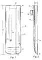
- FIG. 1is a planar view of an inner surface of a retractor blade of the invention showing the visualization channel and the utility channel thereof in dotted lines.
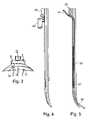
- FIG. 2is a side view of the retractor blade of FIG. 1 .
- FIG. 3is a top view of the retractor blade of FIG. 1 .
- FIG. 4is a sectional view of the retractor blade of Figure one showing the visualization channel.
- FIG. 5is another sectional view of the blade of FIG. 1 , showing the utility channel housing a suction device.
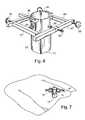
- FIGS. 6 and 7are perspective views of the support frame and retractor blades which make up the minimally invasive fixation system of the invention with the blades in the fully extended position.
- FIG. 8is an isolated top view of the retractor system of the invention.
- FIG. 9is plan view of another version of the retractor blade of the invention, showing a tissue retractor incorporated into the retractor blade.
- FIG. 10is a side view of the retractor blade of FIG. 9 , showing further details of the tissue retractor.
- FIG. 11is a simplified, partially schematic view of the retractor blade of FIG. 9 being used to engage the dural sack of a patient.
- FIG. 1there is shown a retractor blade 11 of the type used in the practice of the present invention.
- the retractor blade 11has a substantially elongate, planar body portion 13 having a length “1” and having a thickness (“t” in FIG. 2 ).
- the body portion 13is also defined by an outer planar surface 15 and an inner planar surface 17 .
- the body portionis generally uniform in thickness along the width thereof but tapers from an upper extent 19 as it approaches a lower extent 21 , terminating in a tip region 23 .
- the elongate body portion 13 of the retractor bladehas incorporated therein at least one visualization channel 25 which, in the embodiment of FIG. 1 , runs from the upper extent 19 down about 4 ⁇ 5 of the length of the blade.
- the visualization channel 25is used to house a light source which is integral with the blade itself.
- the light sourcecould be a light bulb 27 which is connected by electrical wires running up the channel 25 to a suitable power source, such as the battery pack 29 which is carried on the exterior of the blade body portion.
- the light sourcemight be a bulb or other type light source located in the upper extent of the blade having an associated fiber optic strand or cable which leads to a digital light hole (which could also be represented by the object 27 in FIG. 1 ). Again, the light source would be powered by the battery pack 29 .
- the visualization channelmight also be used to house a camera or a scope such as an endoscopic instrument of the type used in a specific surgical procedure.
- a surgeon who prefers direct visualization by looking down the portal, or the surgeon who prefers indirect visualization with a scopecan use the system of the invention.
- the system of the inventionoffers superior lighting and visualization when compared to systems presently on the market by incorporation of the light, the scope, or additional utility device integrally into the retractor blade.
- the integral battery packalso eliminates the need for cords and cannulas from the portal visual site, thereby increasing the area in the visual field. A larger visual field increases the surgeon's ability to identify anatomy and operate with correct surgical orientation.
- the body portion 13 of the retractor blademay also include an elongate utility channel 31 which extends from the upper extent 19 of the blade substantially along the entire length “1” to the lower extent 21 , thereof.
- the utility channel 31terminates in an end opening 33 .
- the utility channel 31houses a selected utility device which is used during surgery.
- the channel 31 in FIG. 5houses a suction device 35 .
- the suction device 35has an upper end 37 and a lower end 39 which is dispatchable from the end opening 33 in the blade lower extent 21 into the surgical site.
- the suction device 35has incorporated therein a coiled wire 41 which acts as a spring and which can be controlled by the surgeon through tension on the upper, exposed end 37 to allow a desired placement of the suction device into the surgical site.
- FIG. 8there is shown a support frame for use with the retractor blade system of the invention, designated generally as 43 .
- the support frame 43has opposing horizontally oriented sides 45 , 47 and 49 , 51 , respectively, the sides being arranged to lie in a common plane generally perpendicular to one another in use.
- sides 49 , 51are arranged generally perpendicular to sides 45 , 47 , in use.
- At least selected ones of the sides 45 , 47 , 49 , 51are provided with holding fixtures for engaging a retractor blade.
- each side of the frame 43has a holding fixture, designated as 53 , 55 , 57 , 59 .
- the holding fixturescan be as simple as flanges having internal channels, e.g., channel 61 , for receiving mating flanges 63 , 65 , 67 , 69 provided on the outer planar surface 15 of the retractor blade (see FIG. 2 ).
- the channel 61 and mating flange 63form a wedge-shaped interfit in the particular embodiment of the invention illustrated.
- the preferred support frame 43comprises a four sided, substantially square member having an open interior space which is adjustable for engaging patient tissue.
- the support frame 43is used for spreading open an incision in the patient's tissue in substantially a first plane, to create a surgical portal and wherein at least selected sides of the support frame are mechanically coupled together for adjusting the interior space between the sides of the support frame.
- the sides of the support frame 43are coupled together by means of a gear system including adjustment knobs 79 , 81 , 83 , 85 .
- the knobs 79 and 81are used to move sides 49 and 51 in and out in a sidewise lateral direction, as viewed in FIG. 8 .
- the knob 83is used to move side 47 up and down as viewed in FIG. 8 .
- Knob 85is a fine adjustment control which is used to determine the exact final position of flange 55 .
- FIGS. 6 and 7show the support frame and associated retractor blades in place on the spinal region of a patient undergoing a spinal procedure.
- a typical procedurewould involve the following general steps:
- a stab woundis created over the radio logically verified intervertebral site.
- a long spinal needle or guide wireis placed through the stab incision and docked on the inferior portion of the upper vertebral lamina. Placement of the guide wire is verified using a C arm.
- Dilator PlacementDilators are placed over the guide wire and continued sequentially until the last dilator is placed.
- Blade PlacementThe four blades 13 , 71 , 73 , 77 including the visual blade 13 are placed over the last dilator.
- the support frame 43is slid over the blade ends and each blade is docked onto the support frame by engaging the respective flange channels and mating blade flanges (e.g., 55 , 65 ).
- the dilatorsare then removed.
- each bladeis distracted independently until the desired portal width is established in the patient tissue.
- Each bladeis then locked in the desired position by means of the adjustment knobs 79 , 81 , 83 , 85 .
- FIGS. 9–11there is shown an additional version of the retractor blade of the invention in which the elongate body portion of the blade also houses a tissue retractor 87 .
- the tissue retractorhas a first section 89 coplanar with the elongate body portion which is slidably received within an elongate passageway 91 substantially centrally located in the elongate body portion of the retractor blade 93 .
- the tissue retractoralso has a second section 95 which extends outwardly from the body portion of the blade and which is angularly oriented with respect to the first section for engaging tissue within a surgical site. With respect to the inner planar surface ( 17 in FIG. 1 ) of the blade, the second section 95 forms a bow-shaped protruberance as viewed from the side in FIG. 10 .
- FIG. 11shows a tissue retractor 87 of the invention in the form of a dural retractor for retracting a dural sack 97 in the spinal canal of a patient undergoing spinal surgery.
- the second section 95 of the dural retractorengages the dural sack as shown and can be manipulated by means of an exposed knob ( 99 in FIGS. 9 and 10 ) which is used to slide the dural retractor upwardly and downwardly within the elongate passageway 91 provided in the elongate body portion of the retractor blade 93 .
- the dural retractormoves the dural sacks to one side during surgery to thereby widen the field of view for the surgeon.
- the improved retractor blade of the inventionprovides a minimally invasive system which will eliminate many of the limiting factors of the presently existing instruments on the market.
- the retractor blade system of the inventionprovides improved visual and physical access by the surgeon to the surgical field.
- the improved retractor blade system of the inventionprovides for safe and effective disc space preparation and implant insertion while minimizing trauma to tissue surrounding the surgical site.
- Both the surgeon preferring direct visualization by looking down the surgical portal, or the surgeon who prefers indirect visualization with a scopecan use the improved system of the invention.
- the present systemoffers superior lighting and visualization when compared to the systems presently on the market.
- the improved lighting and visualizationis created by incorporation of the light, the scope, and a suction device into a single retractor blade.
- the four blade system of the inventionallows the ability to place space between the blades, which allows variable angles of instrument access through the portal.
- the four independent bladeseasily allow the width of this portal to be adjusted by the surgeon according to the needs required for the surgical procedure.
- the system of the inventionalso allows a surgeon to quickly convert the surgical procedure from a minimally invasive case to an open case by simply changing the position of the blades. It is not necessary to remove the minimally invasive access apparatus and replace it with open system retractors.
Landscapes
- Health & Medical Sciences (AREA)
- Life Sciences & Earth Sciences (AREA)
- Surgery (AREA)
- Molecular Biology (AREA)
- Engineering & Computer Science (AREA)
- Biomedical Technology (AREA)
- Heart & Thoracic Surgery (AREA)
- Medical Informatics (AREA)
- Nuclear Medicine, Radiotherapy & Molecular Imaging (AREA)
- Animal Behavior & Ethology (AREA)
- General Health & Medical Sciences (AREA)
- Public Health (AREA)
- Veterinary Medicine (AREA)
- Oral & Maxillofacial Surgery (AREA)
- Pathology (AREA)
- Surgical Instruments (AREA)
Abstract
Description
Claims (15)
Priority Applications (3)
| Application Number | Priority Date | Filing Date | Title |
|---|---|---|---|
| US10/867,354US7150714B2 (en) | 2004-06-14 | 2004-06-14 | Minimally invasive surgical spinal exposure system |
| EP05758535.8AEP1768544B1 (en) | 2004-06-14 | 2005-06-13 | Minimally invasive surgical spinal exposure system |
| PCT/US2005/020843WO2005122871A2 (en) | 2004-06-14 | 2005-06-13 | Minimally invasive surgical spinal exposure system |
Applications Claiming Priority (1)
| Application Number | Priority Date | Filing Date | Title |
|---|---|---|---|
| US10/867,354US7150714B2 (en) | 2004-06-14 | 2004-06-14 | Minimally invasive surgical spinal exposure system |
Publications (2)
| Publication Number | Publication Date |
|---|---|
| US20050277812A1 US20050277812A1 (en) | 2005-12-15 |
| US7150714B2true US7150714B2 (en) | 2006-12-19 |
Family
ID=35461396
Family Applications (1)
| Application Number | Title | Priority Date | Filing Date |
|---|---|---|---|
| US10/867,354Expired - LifetimeUS7150714B2 (en) | 2004-06-14 | 2004-06-14 | Minimally invasive surgical spinal exposure system |
Country Status (3)
| Country | Link |
|---|---|
| US (1) | US7150714B2 (en) |
| EP (1) | EP1768544B1 (en) |
| WO (1) | WO2005122871A2 (en) |
Cited By (63)
| Publication number | Priority date | Publication date | Assignee | Title |
|---|---|---|---|---|
| US20070060793A1 (en)* | 2005-08-30 | 2007-03-15 | Degould Michael D | Suction retraction instrument for surgery |
| US20070083086A1 (en)* | 2005-10-11 | 2007-04-12 | Levahn Intellectual Property Holding Company, Llc | Shaped retractor blade |
| US20070100211A1 (en)* | 2005-11-02 | 2007-05-03 | Depuy Spine, Inc. | Illuminated surgical access system including a surgical access device and coupled light emitter |
| WO2008131084A3 (en)* | 2007-04-17 | 2009-01-08 | K2M Inc | Minimally open interbody access retraction device and surgical method |
| US20090101567A1 (en)* | 2007-10-20 | 2009-04-23 | Robb Benson | Method and Apparatus for the Purification of Salty Streams and the Removal of Particulates Therefrom |
| US20090105546A1 (en)* | 2007-10-23 | 2009-04-23 | Zimmer Spine, Inc. | Surgical access system and method of using the same |
| US20090188856A1 (en)* | 2007-10-20 | 2009-07-30 | Robb Benson | Externally Centering Filter Element or Cartridge and Housing and System Utilizing the Same |
| US7758501B2 (en) | 2006-01-04 | 2010-07-20 | Depuy Spine, Inc. | Surgical reactors and methods of minimally invasive surgery |
| US20100280325A1 (en)* | 2009-04-30 | 2010-11-04 | Tamer Ibrahim | Retractors and surgical systems including the same |
| US20110028792A1 (en)* | 2009-07-28 | 2011-02-03 | Tamer Ibrahim | Tissue retractors with fluid evacuation/infusion and/or light emission capability |
| US20110065999A1 (en)* | 2008-05-07 | 2011-03-17 | James Manzanares | Method and apparatus for laterally accessing an intervertebral disc space |
| US7918792B2 (en) | 2006-01-04 | 2011-04-05 | Depuy Spine, Inc. | Surgical retractor for use with minimally invasive spinal stabilization systems and methods of minimally invasive surgery |
| US7955257B2 (en) | 2006-01-05 | 2011-06-07 | Depuy Spine, Inc. | Non-rigid surgical retractor |
| US7981031B2 (en) | 2006-01-04 | 2011-07-19 | Depuy Spine, Inc. | Surgical access devices and methods of minimally invasive surgery |
| US8038611B2 (en) | 2003-12-18 | 2011-10-18 | Depuy Spine, Inc. | Surgical methods and surgical kits |
| US8088066B2 (en)* | 2007-10-24 | 2012-01-03 | Invuity, Inc. | Blade insert illuminator |
| US8357184B2 (en) | 2009-11-10 | 2013-01-22 | Nuvasive, Inc. | Method and apparatus for performing spinal surgery |
| US20140005489A1 (en)* | 2012-06-27 | 2014-01-02 | CamPlex LLC | Surgical retractor with video cameras |
| US8636655B1 (en) | 2010-01-19 | 2014-01-28 | Ronald Childs | Tissue retraction system and related methods |
| US20140257039A1 (en)* | 2013-03-08 | 2014-09-11 | Joel Feldman | Surgical retractor with smoke evacuator |
| US20150025324A1 (en)* | 2012-01-31 | 2015-01-22 | Shaw P. Wan | Surgical retractor with light |
| US8974381B1 (en)* | 2011-04-26 | 2015-03-10 | Nuvasive, Inc. | Cervical retractor |
| WO2015042483A3 (en)* | 2013-09-20 | 2015-05-14 | Camplex, Inc. | Surgical visualization systems |
| US20150272694A1 (en)* | 2012-06-27 | 2015-10-01 | CamPlex LLC | Surgical visualization system |
| US9151462B2 (en) | 2011-12-21 | 2015-10-06 | Gr Enterprises And Technologies | Light guide diffuser, and methods |
| US20150297208A1 (en)* | 2014-04-22 | 2015-10-22 | University Hospitals Case Medical Center | Spine retractor |
| US9307972B2 (en) | 2011-05-10 | 2016-04-12 | Nuvasive, Inc. | Method and apparatus for performing spinal fusion surgery |
| US20160128721A1 (en)* | 2013-07-05 | 2016-05-12 | Jan Persson | Surgical instrument |
| US20160256191A1 (en)* | 2015-03-02 | 2016-09-08 | Warsaw Orthopedic, Inc. | Surgical cannula with channels for irrigation and suction |
| US9675389B2 (en) | 2009-12-07 | 2017-06-13 | Samy Abdou | Devices and methods for minimally invasive spinal stabilization and instrumentation |
| US20170172404A1 (en)* | 2005-04-01 | 2017-06-22 | Welch Allyn, Inc. | Vaginal speculum apparatus |
| US9782159B2 (en) | 2013-03-13 | 2017-10-10 | Camplex, Inc. | Surgical visualization systems |
| US9795370B2 (en) | 2014-08-13 | 2017-10-24 | Nuvasive, Inc. | Minimally disruptive retractor and associated methods for spinal surgery |
| US20170333023A1 (en)* | 2016-05-20 | 2017-11-23 | Choicespine, Lp | Access Instruments To Extend A Surgical Working Channel |
| US10028651B2 (en) | 2013-09-20 | 2018-07-24 | Camplex, Inc. | Surgical visualization systems and displays |
| US10046175B2 (en) | 2011-12-21 | 2018-08-14 | Spectrum Medical Technologies, Llc | Light delivery systems and related methods of use |
| US20180263612A1 (en)* | 2017-03-15 | 2018-09-20 | C. Daniel Smith | Surgical retractor and wire passer |
| US10149674B2 (en) | 2015-08-12 | 2018-12-11 | K2M, Inc. | Orthopedic surgical system including surgical access systems, distraction systems, and methods of using same |
| US10499894B2 (en) | 2015-08-12 | 2019-12-10 | K2M, Inc. | Orthopedic surgical system including surgical access systems, distraction systems, and methods of using same |
| US10548740B1 (en) | 2016-10-25 | 2020-02-04 | Samy Abdou | Devices and methods for vertebral bone realignment |
| US10575961B1 (en) | 2011-09-23 | 2020-03-03 | Samy Abdou | Spinal fixation devices and methods of use |
| US10687797B2 (en) | 2008-12-18 | 2020-06-23 | Howmedica Osteonics Corp. | Lateral access system for the lumbar spine |
| US10695105B2 (en) | 2012-08-28 | 2020-06-30 | Samy Abdou | Spinal fixation devices and methods of use |
| US10702353B2 (en) | 2014-12-05 | 2020-07-07 | Camplex, Inc. | Surgical visualizations systems and displays |
| US10857003B1 (en) | 2015-10-14 | 2020-12-08 | Samy Abdou | Devices and methods for vertebral stabilization |
| US10918455B2 (en) | 2017-05-08 | 2021-02-16 | Camplex, Inc. | Variable light source |
| US10918498B2 (en) | 2004-11-24 | 2021-02-16 | Samy Abdou | Devices and methods for inter-vertebral orthopedic device placement |
| US10966798B2 (en) | 2015-11-25 | 2021-04-06 | Camplex, Inc. | Surgical visualization systems and displays |
| US10973648B1 (en) | 2016-10-25 | 2021-04-13 | Samy Abdou | Devices and methods for vertebral bone realignment |
| US11006982B2 (en) | 2012-02-22 | 2021-05-18 | Samy Abdou | Spinous process fixation devices and methods of use |
| US20210169460A1 (en)* | 2011-08-19 | 2021-06-10 | Nuvasive, Inc. | Surgical retractor system and methods of use |
| US11154378B2 (en) | 2015-03-25 | 2021-10-26 | Camplex, Inc. | Surgical visualization systems and displays |
| US11166709B2 (en) | 2016-08-23 | 2021-11-09 | Stryker European Operations Holdings Llc | Instrumentation and methods for the implantation of spinal implants |
| US11173040B2 (en) | 2012-10-22 | 2021-11-16 | Cogent Spine, LLC | Devices and methods for spinal stabilization and instrumentation |
| US11179248B2 (en) | 2018-10-02 | 2021-11-23 | Samy Abdou | Devices and methods for spinal implantation |
| US11191532B2 (en) | 2018-03-30 | 2021-12-07 | Stryker European Operations Holdings Llc | Lateral access retractor and core insertion |
| US11382711B2 (en) | 2008-08-13 | 2022-07-12 | Invuity, Inc. | Cyclo olefin polymer and copolymer medical devices |
| US11413029B2 (en) | 2018-10-24 | 2022-08-16 | Stryker European Operations Holdings Llc | Anterior to psoas instrumentation |
| US11464504B2 (en) | 2017-08-17 | 2022-10-11 | Stryker European Operations Holdings Llc | Lateral access bridges, shims and lighting including rod lighting |
| US11564674B2 (en) | 2019-11-27 | 2023-01-31 | K2M, Inc. | Lateral access system and method of use |
| US11707294B2 (en) | 2018-02-15 | 2023-07-25 | Minnetronix Neuro, Inc. | Medical device for accessing the central nervous system |
| US11974775B2 (en) | 2020-01-22 | 2024-05-07 | Minnetronix Neuro, Inc. | Medical device for accessing the central nervous system |
| US12171419B2 (en) | 2021-10-06 | 2024-12-24 | K2M, Inc. | Offset Hohmann |
Families Citing this family (42)
| Publication number | Priority date | Publication date | Assignee | Title |
|---|---|---|---|---|
| EP1417000B1 (en) | 2001-07-11 | 2018-07-11 | Nuvasive, Inc. | System for determining nerve proximity during surgery |
| JP2005503857A (en) | 2001-09-25 | 2005-02-10 | ヌバシブ, インコーポレイテッド | Systems and methods for performing surgical procedures and surgical diagnosis |
| JP3913506B2 (en)* | 2001-09-26 | 2007-05-09 | 三洋電機株式会社 | Disc recording or playback device with a tray that can be moved up and down |
| US7582058B1 (en) | 2002-06-26 | 2009-09-01 | Nuvasive, Inc. | Surgical access system and related methods |
| US8137284B2 (en) | 2002-10-08 | 2012-03-20 | Nuvasive, Inc. | Surgical access system and related methods |
| US7935054B2 (en)* | 2002-10-25 | 2011-05-03 | K2M, Inc. | Minimal access lumbar diskectomy instrumentation and method |
| US7850608B2 (en) | 2002-10-25 | 2010-12-14 | K2M, Inc. | Minimal incision maximal access MIS spine instrumentation and method |
| US7887482B2 (en)* | 2002-10-25 | 2011-02-15 | K2M, Inc. | Minimal access lumbar diskectomy instrumentation and method |
| US7946982B2 (en)* | 2002-10-25 | 2011-05-24 | K2M, Inc. | Minimal incision maximal access MIS spine instrumentation and method |
| US6849064B2 (en)* | 2002-10-25 | 2005-02-01 | James S. Hamada | Minimal access lumbar diskectomy instrumentation and method |
| US7691057B2 (en) | 2003-01-16 | 2010-04-06 | Nuvasive, Inc. | Surgical access system and related methods |
| JP4463819B2 (en) | 2003-09-25 | 2010-05-19 | ヌヴァシヴ インコーポレイテッド | Surgical access system |
| US7905840B2 (en) | 2003-10-17 | 2011-03-15 | Nuvasive, Inc. | Surgical access system and related methods |
| US9055934B2 (en)* | 2004-08-26 | 2015-06-16 | Zimmer Spine, Inc. | Methods and apparatus for access to and/or treatment of the spine |
| US8911364B2 (en)* | 2005-09-08 | 2014-12-16 | DePuy Synthes Products, LLC | Spine retractor and distractor device |
| US8267859B2 (en)* | 2005-09-28 | 2012-09-18 | Holmed Corporation | Spreader insert for a retractor system |
| US7985179B2 (en) | 2006-01-23 | 2011-07-26 | Pioneer Surgical Technology | Retraction apparatus and method of use |
| US8430813B2 (en)* | 2006-05-26 | 2013-04-30 | Depuy Spine, Inc. | Illuminated surgical access system including a surgical access device and integrated light emitter |
| US8992425B2 (en) | 2006-06-06 | 2015-03-31 | Globus Medical, Inc. | Surgical retractor system |
| US7935053B2 (en) | 2006-06-06 | 2011-05-03 | Globus Medical, Inc | Surgical Retractor System |
| US7892174B2 (en)* | 2006-07-19 | 2011-02-22 | Zimmer Spine, Inc. | Surgical access system and method of using the same |
| US8262569B2 (en)* | 2006-07-19 | 2012-09-11 | Zimmer Spine, Inc. | Surgical access system and method of using the same |
| US7922658B2 (en)* | 2006-11-09 | 2011-04-12 | Ebi, Llc | Surgical retractor device and related methods |
| US7931589B2 (en)* | 2006-11-09 | 2011-04-26 | Ebi, Llc | Surgical retractor device and related methods |
| US8062217B2 (en) | 2007-01-26 | 2011-11-22 | Theken Spine, Llc | Surgical retractor with removable blades and method of use |
| US8202216B2 (en)* | 2007-03-08 | 2012-06-19 | Warsaw Orthopedic, Inc. | Tissue retractor |
| US8852089B2 (en)* | 2007-08-01 | 2014-10-07 | Warsaw Orthopedic, Inc. | Instrumentation for tissue retraction |
| US20090171392A1 (en)* | 2007-12-04 | 2009-07-02 | Javier Garcia-Bengochea | Guide wire mounting collar for spinal fixation using minimally invasive surgical techniques |
| US8262570B2 (en)* | 2008-05-30 | 2012-09-11 | Pioneer Surgical Technology, Inc. | Retraction apparatus and method of use |
| USD626223S1 (en) | 2008-10-22 | 2010-10-26 | Ebi, Llc | Tip portion of a surgical retractor blade |
| DE102009018139A1 (en)* | 2009-04-16 | 2010-10-21 | Aesculap Ag | Surgical retraction device |
| US8449463B2 (en)* | 2010-10-08 | 2013-05-28 | K2M, Inc. | Lateral access system and method of use |
| US8702600B2 (en) | 2011-03-08 | 2014-04-22 | Pioneer Surgical Technology, Inc. | Apparatus and method for enlarging an incision |
| US10357239B2 (en) | 2011-03-08 | 2019-07-23 | Pioneer Surgical Technology, Inc. | Apparatus and method for enlarging an incision |
| US9579095B2 (en) | 2011-03-08 | 2017-02-28 | Pioneer Surgical Technology, Inc. | Apparatus and method for enlarging an incision |
| US8790406B1 (en) | 2011-04-01 | 2014-07-29 | William D. Smith | Systems and methods for performing spine surgery |
| US9113853B1 (en) | 2011-08-31 | 2015-08-25 | Nuvasive, Inc. | Systems and methods for performing spine surgery |
| US9622779B2 (en)* | 2011-10-27 | 2017-04-18 | DePuy Synthes Products, Inc. | Method and devices for a sub-splenius / supra-levator scapulae surgical access technique |
| US9084591B2 (en) | 2012-10-23 | 2015-07-21 | Neurostructures, Inc. | Retractor |
| US9855027B2 (en)* | 2012-10-24 | 2018-01-02 | Blackstone Medical, Inc. | Retractor device and method |
| US9693761B2 (en) | 2012-10-24 | 2017-07-04 | Blackstone Medical, Inc. | Retractor device and method |
| US11627952B2 (en) | 2020-06-29 | 2023-04-18 | Surgalign Spine Technologies, Inc. | Surgical retractor |
Citations (37)
| Publication number | Priority date | Publication date | Assignee | Title |
|---|---|---|---|---|
| US475975A (en) | 1892-05-31 | Speculum | ||
| US497064A (en) | 1893-05-09 | Speculum | ||
| US1157202A (en) | 1913-10-14 | 1915-10-19 | Uri C Bates | Surgical apparatus. |
| US1246338A (en) | 1916-08-21 | 1917-11-13 | Isaac J Smit | Illuminated transparent retractor. |
| US3626471A (en) | 1969-10-13 | 1971-12-07 | Robert E Florin | Illuminated suction brain retractor |
| US3965890A (en) | 1974-10-18 | 1976-06-29 | William Kohlmann Gauthier | Surgical retractor |
| US4156424A (en) | 1978-05-01 | 1979-05-29 | Burgin Kermit H | Locking adjustable speculum |
| US4300541A (en) | 1979-02-09 | 1981-11-17 | Kermit Burgin | Speculum lens structure |
| US4562832A (en)* | 1984-01-21 | 1986-01-07 | Wilder Joseph R | Medical instrument and light pipe illumination assembly |
| US4867141A (en)* | 1986-06-18 | 1989-09-19 | Olympus Optical Co., Ltd. | Medical treatment apparatus utilizing ultrasonic wave |
| US4926849A (en) | 1986-12-19 | 1990-05-22 | Downey Ernest L | Apparatus for separating vertebrae |
| US5512038A (en) | 1993-11-15 | 1996-04-30 | O'neal; Darrell D. | Spinal retractor apparatus having a curved blade |
| US5520611A (en) | 1993-12-16 | 1996-05-28 | Rao; Shekar | Illuminated retractor |
| US5616117A (en) | 1995-08-03 | 1997-04-01 | Ohio Medical Instrument Company, Inc. | Self locking surgical retractor |
| US5728046A (en) | 1995-06-23 | 1998-03-17 | Aesculap Ag | Surgical retractor |
| US5755660A (en)* | 1995-10-31 | 1998-05-26 | Tyagi; Narendra S. | Combination surgical retractor, light source, spreader, and suction apparatus |
| US5785648A (en)* | 1996-10-09 | 1998-07-28 | David Min, M.D., Inc. | Speculum |
| US5795291A (en) | 1994-11-10 | 1998-08-18 | Koros; Tibor | Cervical retractor system |
| US5813978A (en)* | 1994-07-19 | 1998-09-29 | Atlantis Surgical, Inc. | Method and apparatus for direct access endoscopic surgery |
| US5882298A (en) | 1998-08-05 | 1999-03-16 | Minnesota Scientific, Inc. | Retractor assembly with connecting pin and method for removably assembling |
| US5908382A (en) | 1998-07-08 | 1999-06-01 | Koros; Tibor B. | Minimally invasive retractor for internal mammary artery harvesting |
| US5928139A (en)* | 1998-04-24 | 1999-07-27 | Koros; Tibor B. | Retractor with adjustable length blades and light pipe guides |
| US5944658A (en) | 1997-09-23 | 1999-08-31 | Koros; Tibor B. | Lumbar spinal fusion retractor and distractor system |
| USD415274S (en) | 1998-04-17 | 1999-10-12 | Koros Tibor B | Adjustable length retractor/distractor blade |
| US5993385A (en) | 1997-08-18 | 1999-11-30 | Johnston; Terry | Self-aligning side-loading surgical retractor |
| US6139493A (en)* | 1998-07-08 | 2000-10-31 | Koros; Tibor B. | Retractor with adjustable length blades and light pipe guides |
| US6185356B1 (en) | 1995-06-27 | 2001-02-06 | Lumitex, Inc. | Protective cover for a lighting device |
| US6224545B1 (en) | 1998-07-24 | 2001-05-01 | Core Surgical, Inc. | Surgical retractor and method for use |
| US6416467B1 (en) | 2000-09-15 | 2002-07-09 | Mcmillin Matthew | Vaginal speculum and method of using same |
| US6464634B1 (en) | 2000-09-27 | 2002-10-15 | Depuy Acromed, Inc. | Surgical retractor system |
| US20030095781A1 (en) | 1997-07-02 | 2003-05-22 | Williams Jeffrey B. | Illuminated surgical retractor |
| US6616605B2 (en) | 2001-02-15 | 2003-09-09 | Genesee Biomedical, Inc. | Quadretractor and method of use |
| US6712795B1 (en) | 2002-06-07 | 2004-03-30 | Lester Cohen | Surgical procedure and apparatus |
| US20040087833A1 (en) | 2002-10-30 | 2004-05-06 | Thomas Bauer | Retractor |
| US20040215199A1 (en) | 2002-08-01 | 2004-10-28 | Zinkel John M. | Method for spinal surgery |
| US6869398B2 (en) | 2003-01-06 | 2005-03-22 | Theodore G. Obenchain | Four-blade surgical speculum |
| US6945933B2 (en) | 2002-06-26 | 2005-09-20 | Sdgi Holdings, Inc. | Instruments and methods for minimally invasive tissue retraction and surgery |
Family Cites Families (3)
| Publication number | Priority date | Publication date | Assignee | Title |
|---|---|---|---|---|
| US1706500A (en)* | 1927-08-01 | 1929-03-26 | Henry J Smith | Surgical retractor |
| US4627421A (en)* | 1984-08-03 | 1986-12-09 | Symbas Panagiotis N | Sternal retractor |
| US6024697A (en)* | 1999-01-11 | 2000-02-15 | Pisarik; Paul | Multi-bladed speculum for dilating a body cavity |
- 2004
- 2004-06-14USUS10/867,354patent/US7150714B2/ennot_activeExpired - Lifetime
- 2005
- 2005-06-13EPEP05758535.8Apatent/EP1768544B1/ennot_activeExpired - Lifetime
- 2005-06-13WOPCT/US2005/020843patent/WO2005122871A2/enactiveApplication Filing
Patent Citations (39)
| Publication number | Priority date | Publication date | Assignee | Title |
|---|---|---|---|---|
| US475975A (en) | 1892-05-31 | Speculum | ||
| US497064A (en) | 1893-05-09 | Speculum | ||
| US1157202A (en) | 1913-10-14 | 1915-10-19 | Uri C Bates | Surgical apparatus. |
| US1246338A (en) | 1916-08-21 | 1917-11-13 | Isaac J Smit | Illuminated transparent retractor. |
| US3626471A (en) | 1969-10-13 | 1971-12-07 | Robert E Florin | Illuminated suction brain retractor |
| US3965890A (en) | 1974-10-18 | 1976-06-29 | William Kohlmann Gauthier | Surgical retractor |
| US4156424A (en) | 1978-05-01 | 1979-05-29 | Burgin Kermit H | Locking adjustable speculum |
| US4263899A (en) | 1978-05-01 | 1981-04-28 | Burgin Kermit H | Locking adjustable speculum |
| US4300541A (en) | 1979-02-09 | 1981-11-17 | Kermit Burgin | Speculum lens structure |
| US4562832A (en)* | 1984-01-21 | 1986-01-07 | Wilder Joseph R | Medical instrument and light pipe illumination assembly |
| US4867141A (en)* | 1986-06-18 | 1989-09-19 | Olympus Optical Co., Ltd. | Medical treatment apparatus utilizing ultrasonic wave |
| US4926849A (en) | 1986-12-19 | 1990-05-22 | Downey Ernest L | Apparatus for separating vertebrae |
| US5512038A (en) | 1993-11-15 | 1996-04-30 | O'neal; Darrell D. | Spinal retractor apparatus having a curved blade |
| US5520611A (en) | 1993-12-16 | 1996-05-28 | Rao; Shekar | Illuminated retractor |
| US5813978A (en)* | 1994-07-19 | 1998-09-29 | Atlantis Surgical, Inc. | Method and apparatus for direct access endoscopic surgery |
| US5795291A (en) | 1994-11-10 | 1998-08-18 | Koros; Tibor | Cervical retractor system |
| US5728046A (en) | 1995-06-23 | 1998-03-17 | Aesculap Ag | Surgical retractor |
| US6185356B1 (en) | 1995-06-27 | 2001-02-06 | Lumitex, Inc. | Protective cover for a lighting device |
| US6504985B2 (en) | 1995-06-27 | 2003-01-07 | Lumitex, Inc. | Illuminated surgical retractor |
| US5616117A (en) | 1995-08-03 | 1997-04-01 | Ohio Medical Instrument Company, Inc. | Self locking surgical retractor |
| US5755660A (en)* | 1995-10-31 | 1998-05-26 | Tyagi; Narendra S. | Combination surgical retractor, light source, spreader, and suction apparatus |
| US5785648A (en)* | 1996-10-09 | 1998-07-28 | David Min, M.D., Inc. | Speculum |
| US20030095781A1 (en) | 1997-07-02 | 2003-05-22 | Williams Jeffrey B. | Illuminated surgical retractor |
| US5993385A (en) | 1997-08-18 | 1999-11-30 | Johnston; Terry | Self-aligning side-loading surgical retractor |
| US5944658A (en) | 1997-09-23 | 1999-08-31 | Koros; Tibor B. | Lumbar spinal fusion retractor and distractor system |
| USD415274S (en) | 1998-04-17 | 1999-10-12 | Koros Tibor B | Adjustable length retractor/distractor blade |
| US5928139A (en)* | 1998-04-24 | 1999-07-27 | Koros; Tibor B. | Retractor with adjustable length blades and light pipe guides |
| US5908382A (en) | 1998-07-08 | 1999-06-01 | Koros; Tibor B. | Minimally invasive retractor for internal mammary artery harvesting |
| US6139493A (en)* | 1998-07-08 | 2000-10-31 | Koros; Tibor B. | Retractor with adjustable length blades and light pipe guides |
| US6224545B1 (en) | 1998-07-24 | 2001-05-01 | Core Surgical, Inc. | Surgical retractor and method for use |
| US5882298A (en) | 1998-08-05 | 1999-03-16 | Minnesota Scientific, Inc. | Retractor assembly with connecting pin and method for removably assembling |
| US6416467B1 (en) | 2000-09-15 | 2002-07-09 | Mcmillin Matthew | Vaginal speculum and method of using same |
| US6464634B1 (en) | 2000-09-27 | 2002-10-15 | Depuy Acromed, Inc. | Surgical retractor system |
| US6616605B2 (en) | 2001-02-15 | 2003-09-09 | Genesee Biomedical, Inc. | Quadretractor and method of use |
| US6712795B1 (en) | 2002-06-07 | 2004-03-30 | Lester Cohen | Surgical procedure and apparatus |
| US6945933B2 (en) | 2002-06-26 | 2005-09-20 | Sdgi Holdings, Inc. | Instruments and methods for minimally invasive tissue retraction and surgery |
| US20040215199A1 (en) | 2002-08-01 | 2004-10-28 | Zinkel John M. | Method for spinal surgery |
| US20040087833A1 (en) | 2002-10-30 | 2004-05-06 | Thomas Bauer | Retractor |
| US6869398B2 (en) | 2003-01-06 | 2005-03-22 | Theodore G. Obenchain | Four-blade surgical speculum |
Cited By (168)
| Publication number | Priority date | Publication date | Assignee | Title |
|---|---|---|---|---|
| US8622897B2 (en) | 2003-12-18 | 2014-01-07 | DePuy Synthes Products, LLC | Surgical methods and surgical kits |
| US8602984B2 (en) | 2003-12-18 | 2013-12-10 | DePuy Synthes Products, LLC | Surgical retractor systems and illuminated cannulae |
| US8038611B2 (en) | 2003-12-18 | 2011-10-18 | Depuy Spine, Inc. | Surgical methods and surgical kits |
| US10869657B2 (en) | 2003-12-18 | 2020-12-22 | DePuy Synthes Products, Inc. | Surgical retractor systems and illuminated cannulae |
| US11096799B2 (en) | 2004-11-24 | 2021-08-24 | Samy Abdou | Devices and methods for inter-vertebral orthopedic device placement |
| US11992423B2 (en) | 2004-11-24 | 2024-05-28 | Samy Abdou | Devices and methods for inter-vertebral orthopedic device placement |
| US10918498B2 (en) | 2004-11-24 | 2021-02-16 | Samy Abdou | Devices and methods for inter-vertebral orthopedic device placement |
| US9883792B2 (en) | 2005-04-01 | 2018-02-06 | Welch Allyn, Inc. | Vaginal speculum apparatus |
| US9949633B2 (en)* | 2005-04-01 | 2018-04-24 | Welch Allyn, Inc. | Vaginal speculum apparatus |
| US12262878B2 (en) | 2005-04-01 | 2025-04-01 | Welch Allyn, Inc. | Vaginal speculum apparatus |
| US11291359B2 (en) | 2005-04-01 | 2022-04-05 | Welch Allyn, Inc. | Vaginal speculum apparatus |
| US20170172404A1 (en)* | 2005-04-01 | 2017-06-22 | Welch Allyn, Inc. | Vaginal speculum apparatus |
| US10376138B2 (en) | 2005-04-01 | 2019-08-13 | Welch Allyn, Inc. | Vaginal speculum apparatus |
| US8221316B2 (en)* | 2005-08-30 | 2012-07-17 | Degould Michael D | Suction retraction instrument for surgery |
| US20070060793A1 (en)* | 2005-08-30 | 2007-03-15 | Degould Michael D | Suction retraction instrument for surgery |
| US20070083086A1 (en)* | 2005-10-11 | 2007-04-12 | Levahn Intellectual Property Holding Company, Llc | Shaped retractor blade |
| US9005118B2 (en) | 2005-11-02 | 2015-04-14 | DePuy Synthes Products, LLC | Illuminated surgical access system including a surgical access device and coupled light emitter |
| US20110021882A1 (en)* | 2005-11-02 | 2011-01-27 | Sean Selover | Illuminated surgical access system including a surgical access device and coupled light emitter |
| US7874982B2 (en)* | 2005-11-02 | 2011-01-25 | Depuy Spine, Inc. | Illuminated surgical access system including a surgical access device and coupled light emitter |
| US20070100211A1 (en)* | 2005-11-02 | 2007-05-03 | Depuy Spine, Inc. | Illuminated surgical access system including a surgical access device and coupled light emitter |
| US7918792B2 (en) | 2006-01-04 | 2011-04-05 | Depuy Spine, Inc. | Surgical retractor for use with minimally invasive spinal stabilization systems and methods of minimally invasive surgery |
| US7981031B2 (en) | 2006-01-04 | 2011-07-19 | Depuy Spine, Inc. | Surgical access devices and methods of minimally invasive surgery |
| US7758501B2 (en) | 2006-01-04 | 2010-07-20 | Depuy Spine, Inc. | Surgical reactors and methods of minimally invasive surgery |
| US8517935B2 (en) | 2006-01-04 | 2013-08-27 | DePuy Synthes Products, LLC | Surgical retractors and methods of minimally invasive surgery |
| US8550995B2 (en) | 2006-01-04 | 2013-10-08 | DePuy Synthes Products, LLC | Surgical access devices and methods of minimally invasive surgery |
| US7955257B2 (en) | 2006-01-05 | 2011-06-07 | Depuy Spine, Inc. | Non-rigid surgical retractor |
| US9254126B2 (en) | 2006-01-05 | 2016-02-09 | DePuy Synthes Products, Inc. | Non-rigid surgical retractor |
| US11083447B2 (en) | 2007-04-17 | 2021-08-10 | K2M, Inc. | Minimally open interbody access retraction device and surgical method |
| US10405841B2 (en) | 2007-04-17 | 2019-09-10 | K2M, Inc. | Minimally open interbody access retraction device and surgical method |
| US9675337B2 (en) | 2007-04-17 | 2017-06-13 | K2M, Inc. | Minimally open interbody access retraction device and surgical method |
| WO2008131084A3 (en)* | 2007-04-17 | 2009-01-08 | K2M Inc | Minimally open interbody access retraction device and surgical method |
| US11812940B2 (en) | 2007-04-17 | 2023-11-14 | K2M, Inc. | Minimally open interbody access retraction device and surgical method |
| US8979749B2 (en) | 2007-04-17 | 2015-03-17 | K2M, Inc. | Minimally open interbody access retraction device and surgical method |
| US20090101567A1 (en)* | 2007-10-20 | 2009-04-23 | Robb Benson | Method and Apparatus for the Purification of Salty Streams and the Removal of Particulates Therefrom |
| US20090188856A1 (en)* | 2007-10-20 | 2009-07-30 | Robb Benson | Externally Centering Filter Element or Cartridge and Housing and System Utilizing the Same |
| US8641609B2 (en) | 2007-10-23 | 2014-02-04 | Zimmer Spine, Inc. | Surgical access system and method of using the same |
| US20090105546A1 (en)* | 2007-10-23 | 2009-04-23 | Zimmer Spine, Inc. | Surgical access system and method of using the same |
| US8088066B2 (en)* | 2007-10-24 | 2012-01-03 | Invuity, Inc. | Blade insert illuminator |
| US11583175B2 (en) | 2007-10-24 | 2023-02-21 | Invuity, Inc. | Blade insert illuminator |
| US10582844B2 (en) | 2007-10-24 | 2020-03-10 | Invuity, Inc. | Blade insert illuminator |
| US9060707B2 (en) | 2007-10-24 | 2015-06-23 | Invuity, Inc. | Blade insert illuminator |
| US9468366B2 (en) | 2007-10-24 | 2016-10-18 | Invuity, Inc. | Blade insert illuminator |
| US9986901B2 (en) | 2007-10-24 | 2018-06-05 | Invuity, Inc. | Blade insert illuminator |
| US12161301B2 (en) | 2007-10-24 | 2024-12-10 | Invuity, Inc. | Blade insert illuminator |
| US20110065999A1 (en)* | 2008-05-07 | 2011-03-17 | James Manzanares | Method and apparatus for laterally accessing an intervertebral disc space |
| US8808172B2 (en)* | 2008-05-07 | 2014-08-19 | DePuy Synthes Products, LLC | Method and apparatus for laterally accessing an intervertebral disc space |
| US11382711B2 (en) | 2008-08-13 | 2022-07-12 | Invuity, Inc. | Cyclo olefin polymer and copolymer medical devices |
| US10687797B2 (en) | 2008-12-18 | 2020-06-23 | Howmedica Osteonics Corp. | Lateral access system for the lumbar spine |
| US11925342B2 (en) | 2008-12-18 | 2024-03-12 | Howmedica Osteonics Corp. | Lateral access system for the lumbar spine |
| US20100280325A1 (en)* | 2009-04-30 | 2010-11-04 | Tamer Ibrahim | Retractors and surgical systems including the same |
| US8696556B2 (en)* | 2009-07-28 | 2014-04-15 | Endoscopic Technologies, Inc. | Tissue retractors with fluid evacuation/infusion and/or light emission capability |
| US20110028792A1 (en)* | 2009-07-28 | 2011-02-03 | Tamer Ibrahim | Tissue retractors with fluid evacuation/infusion and/or light emission capability |
| US8435269B2 (en) | 2009-11-10 | 2013-05-07 | Nuvasive, Inc. | Method and apparatus for performing spinal fusion surgery |
| US8535320B2 (en) | 2009-11-10 | 2013-09-17 | Nuvasive, Inc. | Method and apparatus for performing spinal surgery |
| US11911078B2 (en) | 2009-11-10 | 2024-02-27 | Nuvasive, Inc. | Method and apparatus for performing spinal surgery |
| US9050146B2 (en) | 2009-11-10 | 2015-06-09 | Nuvasive, Inc. | Method and apparatus for performing spinal surgery |
| US9554833B2 (en) | 2009-11-10 | 2017-01-31 | Nuvasive, Inc. | Method and apparatus for performing spinal surgery |
| US8357184B2 (en) | 2009-11-10 | 2013-01-22 | Nuvasive, Inc. | Method and apparatus for performing spinal surgery |
| US10172652B2 (en) | 2009-11-10 | 2019-01-08 | Nuvasive, Inc. | Method and apparatus for performing spinal surgery |
| US12029453B2 (en) | 2009-11-10 | 2024-07-09 | Nuvasive Inc. | Method and apparatus for performing spinal surgery |
| US12011197B2 (en) | 2009-11-10 | 2024-06-18 | Nuvasive, Inc. | Method and apparatus for performing spinal surgery |
| US10980576B2 (en) | 2009-11-10 | 2021-04-20 | Nuvasive, Inc. | Method and apparatus for performing spinal surgery |
| US10610380B2 (en) | 2009-12-07 | 2020-04-07 | Samy Abdou | Devices and methods for minimally invasive spinal stabilization and instrumentation |
| US10857004B2 (en) | 2009-12-07 | 2020-12-08 | Samy Abdou | Devices and methods for minimally invasive spinal stabilization and instrumentation |
| US10543107B2 (en) | 2009-12-07 | 2020-01-28 | Samy Abdou | Devices and methods for minimally invasive spinal stabilization and instrumentation |
| US11918486B2 (en) | 2009-12-07 | 2024-03-05 | Samy Abdou | Devices and methods for minimally invasive spinal stabilization and instrumentation |
| US9675389B2 (en) | 2009-12-07 | 2017-06-13 | Samy Abdou | Devices and methods for minimally invasive spinal stabilization and instrumentation |
| US10945861B2 (en) | 2009-12-07 | 2021-03-16 | Samy Abdou | Devices and methods for minimally invasive spinal stabilization and instrumentation |
| US8636655B1 (en) | 2010-01-19 | 2014-01-28 | Ronald Childs | Tissue retraction system and related methods |
| US8974381B1 (en)* | 2011-04-26 | 2015-03-10 | Nuvasive, Inc. | Cervical retractor |
| US11759196B2 (en) | 2011-05-10 | 2023-09-19 | Nuvasive, Inc. | Method and apparatus for performing spinal fusion surgery |
| US9307972B2 (en) | 2011-05-10 | 2016-04-12 | Nuvasive, Inc. | Method and apparatus for performing spinal fusion surgery |
| US12035903B2 (en) | 2011-05-10 | 2024-07-16 | Nuvasive, Inc. | Method and apparatus for performing spinal fusion surgery |
| US11154288B1 (en) | 2011-05-10 | 2021-10-26 | Nuvasive, Inc. | Method and apparatus for performing spinal fusion surgery |
| US10231724B1 (en) | 2011-05-10 | 2019-03-19 | Nuvasive, Inc. | Method and apparatus for performing spinal fusion surgery |
| US12256916B2 (en)* | 2011-08-19 | 2025-03-25 | Nuvasive, Inc. | Surgical retractor system and methods of use |
| US20210169460A1 (en)* | 2011-08-19 | 2021-06-10 | Nuvasive, Inc. | Surgical retractor system and methods of use |
| US10575961B1 (en) | 2011-09-23 | 2020-03-03 | Samy Abdou | Spinal fixation devices and methods of use |
| US12167973B2 (en) | 2011-09-23 | 2024-12-17 | Samy Abdou | Spinal fixation devices and methods of use |
| US11517449B2 (en) | 2011-09-23 | 2022-12-06 | Samy Abdou | Spinal fixation devices and methods of use |
| US11324608B2 (en) | 2011-09-23 | 2022-05-10 | Samy Abdou | Spinal fixation devices and methods of use |
| US10046175B2 (en) | 2011-12-21 | 2018-08-14 | Spectrum Medical Technologies, Llc | Light delivery systems and related methods of use |
| US9151462B2 (en) | 2011-12-21 | 2015-10-06 | Gr Enterprises And Technologies | Light guide diffuser, and methods |
| US9730685B2 (en)* | 2012-01-31 | 2017-08-15 | Shaw P. Wan | Surgical retractor with light |
| US20150025324A1 (en)* | 2012-01-31 | 2015-01-22 | Shaw P. Wan | Surgical retractor with light |
| US11839413B2 (en) | 2012-02-22 | 2023-12-12 | Samy Abdou | Spinous process fixation devices and methods of use |
| US11006982B2 (en) | 2012-02-22 | 2021-05-18 | Samy Abdou | Spinous process fixation devices and methods of use |
| US20150272694A1 (en)* | 2012-06-27 | 2015-10-01 | CamPlex LLC | Surgical visualization system |
| US9629523B2 (en)* | 2012-06-27 | 2017-04-25 | Camplex, Inc. | Binocular viewing assembly for a surgical visualization system |
| US10555728B2 (en)* | 2012-06-27 | 2020-02-11 | Camplex, Inc. | Surgical visualization system |
| US12349861B2 (en) | 2012-06-27 | 2025-07-08 | Camplex, Inc. | Hydraulic system for surgical applications |
| US9642606B2 (en)* | 2012-06-27 | 2017-05-09 | Camplex, Inc. | Surgical visualization system |
| US9681796B2 (en) | 2012-06-27 | 2017-06-20 | Camplex, Inc. | Interface for viewing video from cameras on a surgical visualization system |
| US10231607B2 (en) | 2012-06-27 | 2019-03-19 | Camplex, Inc. | Surgical visualization systems |
| US11129521B2 (en) | 2012-06-27 | 2021-09-28 | Camplex, Inc. | Optics for video camera on a surgical visualization system |
| US11889976B2 (en)* | 2012-06-27 | 2024-02-06 | Camplex, Inc. | Surgical visualization systems |
| US20140005489A1 (en)* | 2012-06-27 | 2014-01-02 | CamPlex LLC | Surgical retractor with video cameras |
| US9615728B2 (en) | 2012-06-27 | 2017-04-11 | Camplex, Inc. | Surgical visualization system with camera tracking |
| US9723976B2 (en) | 2012-06-27 | 2017-08-08 | Camplex, Inc. | Optics for video camera on a surgical visualization system |
| US9492065B2 (en)* | 2012-06-27 | 2016-11-15 | Camplex, Inc. | Surgical retractor with video cameras |
| US20180055348A1 (en)* | 2012-06-27 | 2018-03-01 | Camplex, Inc. | Binocular viewing assembly for a surgical visualization system |
| US20140005485A1 (en)* | 2012-06-27 | 2014-01-02 | CamPlex LLC | Binocular viewing assembly for a surgical visualization system |
| US20180055502A1 (en)* | 2012-06-27 | 2018-03-01 | Camplex, Inc. | Surgical visualization system |
| US10925472B2 (en)* | 2012-06-27 | 2021-02-23 | Camplex, Inc. | Binocular viewing assembly for a surgical visualization system |
| US10925589B2 (en) | 2012-06-27 | 2021-02-23 | Camplex, Inc. | Interface for viewing video from cameras on a surgical visualization system |
| US9936863B2 (en) | 2012-06-27 | 2018-04-10 | Camplex, Inc. | Optical assembly providing a surgical microscope view for a surgical visualization system |
| US20220313235A1 (en)* | 2012-06-27 | 2022-10-06 | Camplex, Inc. | Surgical visualization systems |
| US11389146B2 (en)* | 2012-06-27 | 2022-07-19 | Camplex, Inc. | Surgical visualization system |
| US8882662B2 (en)* | 2012-06-27 | 2014-11-11 | Camplex, Inc. | Interface for viewing video from cameras on a surgical visualization system |
| US9216068B2 (en) | 2012-06-27 | 2015-12-22 | Camplex, Inc. | Optics for video cameras on a surgical visualization system |
| US10022041B2 (en) | 2012-06-27 | 2018-07-17 | Camplex, Inc. | Hydraulic system for surgical applications |
| US20240382069A1 (en)* | 2012-06-27 | 2024-11-21 | Camplex, Inc. | Surgical visualization systems |
| US11166706B2 (en) | 2012-06-27 | 2021-11-09 | Camplex, Inc. | Surgical visualization systems |
| US11559336B2 (en) | 2012-08-28 | 2023-01-24 | Samy Abdou | Spinal fixation devices and methods of use |
| US10695105B2 (en) | 2012-08-28 | 2020-06-30 | Samy Abdou | Spinal fixation devices and methods of use |
| US11173040B2 (en) | 2012-10-22 | 2021-11-16 | Cogent Spine, LLC | Devices and methods for spinal stabilization and instrumentation |
| US11918483B2 (en) | 2012-10-22 | 2024-03-05 | Cogent Spine Llc | Devices and methods for spinal stabilization and instrumentation |
| US20140257039A1 (en)* | 2013-03-08 | 2014-09-11 | Joel Feldman | Surgical retractor with smoke evacuator |
| US9782159B2 (en) | 2013-03-13 | 2017-10-10 | Camplex, Inc. | Surgical visualization systems |
| US10932766B2 (en)* | 2013-05-21 | 2021-03-02 | Camplex, Inc. | Surgical visualization systems |
| US20180256145A1 (en)* | 2013-05-21 | 2018-09-13 | Camplex, Inc. | Surgical visualization systems |
| US20160128721A1 (en)* | 2013-07-05 | 2016-05-12 | Jan Persson | Surgical instrument |
| US10568499B2 (en) | 2013-09-20 | 2020-02-25 | Camplex, Inc. | Surgical visualization systems and displays |
| US11147443B2 (en) | 2013-09-20 | 2021-10-19 | Camplex, Inc. | Surgical visualization systems and displays |
| WO2015042483A3 (en)* | 2013-09-20 | 2015-05-14 | Camplex, Inc. | Surgical visualization systems |
| US10028651B2 (en) | 2013-09-20 | 2018-07-24 | Camplex, Inc. | Surgical visualization systems and displays |
| US10881286B2 (en) | 2013-09-20 | 2021-01-05 | Camplex, Inc. | Medical apparatus for use with a surgical tubular retractor |
| US10172601B2 (en)* | 2014-04-22 | 2019-01-08 | University Hospitals Cleveland Medical Center | Spine retractor |
| US20150297208A1 (en)* | 2014-04-22 | 2015-10-22 | University Hospitals Case Medical Center | Spine retractor |
| US12108947B2 (en) | 2014-08-13 | 2024-10-08 | Nuvasive, Inc. | Minimally disruptive retractor and associated methods for spinal surgery |
| US11399816B2 (en) | 2014-08-13 | 2022-08-02 | Nuvasive, Inc. | Minimally disruptive retractor and associated methods for spinal surgery |
| US10660628B2 (en) | 2014-08-13 | 2020-05-26 | Nuvasive, Inc. | Minimally disruptive retractor and associated methods for spinal surgery |
| US9962147B2 (en) | 2014-08-13 | 2018-05-08 | Nuvasive, Inc. | Minimally disruptive retractor and associated methods for spinal surgery |
| US9795370B2 (en) | 2014-08-13 | 2017-10-24 | Nuvasive, Inc. | Minimally disruptive retractor and associated methods for spinal surgery |
| US10702353B2 (en) | 2014-12-05 | 2020-07-07 | Camplex, Inc. | Surgical visualizations systems and displays |
| US20160256191A1 (en)* | 2015-03-02 | 2016-09-08 | Warsaw Orthopedic, Inc. | Surgical cannula with channels for irrigation and suction |
| US11154378B2 (en) | 2015-03-25 | 2021-10-26 | Camplex, Inc. | Surgical visualization systems and displays |
| US11006942B2 (en) | 2015-08-12 | 2021-05-18 | K2M, Inc. | Orthopedic surgical system including surgical access systems, distraction systems, and methods of using same |
| US10149674B2 (en) | 2015-08-12 | 2018-12-11 | K2M, Inc. | Orthopedic surgical system including surgical access systems, distraction systems, and methods of using same |
| US12048426B2 (en) | 2015-08-12 | 2024-07-30 | K2M, Inc. | Orthopedic surgical system including surgical access systems, distraction systems, and methods of using same |
| US10499894B2 (en) | 2015-08-12 | 2019-12-10 | K2M, Inc. | Orthopedic surgical system including surgical access systems, distraction systems, and methods of using same |
| US11246718B2 (en) | 2015-10-14 | 2022-02-15 | Samy Abdou | Devices and methods for vertebral stabilization |
| US10857003B1 (en) | 2015-10-14 | 2020-12-08 | Samy Abdou | Devices and methods for vertebral stabilization |
| US10966798B2 (en) | 2015-11-25 | 2021-04-06 | Camplex, Inc. | Surgical visualization systems and displays |
| US20170333023A1 (en)* | 2016-05-20 | 2017-11-23 | Choicespine, Lp | Access Instruments To Extend A Surgical Working Channel |
| US9867605B2 (en)* | 2016-05-20 | 2018-01-16 | Choicespine, Lp | Access instruments to extend a surgical working channel |
| US12133643B2 (en) | 2016-08-23 | 2024-11-05 | Stryker European Operations Holdings Llc | Instrumentation and methods for the implantation of spinal implants |
| US11166709B2 (en) | 2016-08-23 | 2021-11-09 | Stryker European Operations Holdings Llc | Instrumentation and methods for the implantation of spinal implants |
| US11752008B1 (en) | 2016-10-25 | 2023-09-12 | Samy Abdou | Devices and methods for vertebral bone realignment |
| US11058548B1 (en) | 2016-10-25 | 2021-07-13 | Samy Abdou | Devices and methods for vertebral bone realignment |
| US10744000B1 (en) | 2016-10-25 | 2020-08-18 | Samy Abdou | Devices and methods for vertebral bone realignment |
| US11259935B1 (en) | 2016-10-25 | 2022-03-01 | Samy Abdou | Devices and methods for vertebral bone realignment |
| US10973648B1 (en) | 2016-10-25 | 2021-04-13 | Samy Abdou | Devices and methods for vertebral bone realignment |
| US10548740B1 (en) | 2016-10-25 | 2020-02-04 | Samy Abdou | Devices and methods for vertebral bone realignment |
| US20180263612A1 (en)* | 2017-03-15 | 2018-09-20 | C. Daniel Smith | Surgical retractor and wire passer |
| US10918455B2 (en) | 2017-05-08 | 2021-02-16 | Camplex, Inc. | Variable light source |
| US11464504B2 (en) | 2017-08-17 | 2022-10-11 | Stryker European Operations Holdings Llc | Lateral access bridges, shims and lighting including rod lighting |
| US12290252B2 (en) | 2017-08-17 | 2025-05-06 | Stryker European Operations Holdings Llc | Lateral access bridges, shims and lighting including rod lighting |
| US12232765B2 (en) | 2018-02-15 | 2025-02-25 | Minnetronix Neuro, Inc. | Medical device for accessing the central nervous system |
| US11707294B2 (en) | 2018-02-15 | 2023-07-25 | Minnetronix Neuro, Inc. | Medical device for accessing the central nervous system |
| US11191532B2 (en) | 2018-03-30 | 2021-12-07 | Stryker European Operations Holdings Llc | Lateral access retractor and core insertion |
| US11911016B2 (en) | 2018-03-30 | 2024-02-27 | Stryker European Operations Holdings Llc | Lateral access retractor and core insertion |
| US11179248B2 (en) | 2018-10-02 | 2021-11-23 | Samy Abdou | Devices and methods for spinal implantation |
| US11413029B2 (en) | 2018-10-24 | 2022-08-16 | Stryker European Operations Holdings Llc | Anterior to psoas instrumentation |
| US12256917B2 (en) | 2018-10-24 | 2025-03-25 | Stryker European Operations Holdings Llc | Anterior to psoas instrumentation |
| US11564674B2 (en) | 2019-11-27 | 2023-01-31 | K2M, Inc. | Lateral access system and method of use |
| US11974775B2 (en) | 2020-01-22 | 2024-05-07 | Minnetronix Neuro, Inc. | Medical device for accessing the central nervous system |
| US12171419B2 (en) | 2021-10-06 | 2024-12-24 | K2M, Inc. | Offset Hohmann |
Also Published As
| Publication number | Publication date |
|---|---|
| WO2005122871A3 (en) | 2006-08-24 |
| EP1768544B1 (en) | 2013-05-22 |
| US20050277812A1 (en) | 2005-12-15 |
| WO2005122871A2 (en) | 2005-12-29 |
| EP1768544A2 (en) | 2007-04-04 |
| EP1768544A4 (en) | 2012-02-22 |
Similar Documents
| Publication | Publication Date | Title |
|---|---|---|
| US7150714B2 (en) | Minimally invasive surgical spinal exposure system | |
| US20230046670A1 (en) | Minimally Open Retraction Device | |
| ES2352726T3 (en) | DEVICES FOR RELATED USES OF PERCUTANEOUS SURGERY. | |
| ES2232206T3 (en) | DEVICES FOR PERCUTANEOUS SURGERY. | |
| US6206826B1 (en) | Devices and methods for percutaneous surgery | |
| US11272912B2 (en) | Surgical dilator, retractor and mounting pad | |
| US10709434B2 (en) | Surgical access systems and methods | |
| JP4223812B2 (en) | Percutaneous surgical apparatus and method | |
| JP4717828B2 (en) | Surgical retractor, illuminated cannula, and usage | |
| JP4126089B2 (en) | Endoscopic bone plate positioning device | |
| US20080234550A1 (en) | Minimally Traumatic Portal | |
| US9675334B2 (en) | Surgical dilator, retractor and mounting pad | |
| US20120101341A1 (en) | Surgical access device system and methods of use | |
| US20070276191A1 (en) | Illuminated surgical access system including a surgical access device and integrated light emitter | |
| US7951077B2 (en) | Method and instruments for breast augmentation mammaplasty | |
| US20150045624A1 (en) | Intra-Thoracic Access Device Without Thoracotomy, and Related Methods | |
| CN101217915A (en) | Surgical access device, system, and methods of use | |
| RU74794U1 (en) | Expander | |
| US20240358364A1 (en) | Retractor tube device |
Legal Events
| Date | Code | Title | Description |
|---|---|---|---|
| AS | Assignment | Owner name:ROBERT TYTAN MYLES FAMILY LIMITED PARTNERSHIP, TEX Free format text:ASSIGNMENT OF ASSIGNORS INTEREST;ASSIGNOR:MYLES, ROBERT T.;REEL/FRAME:015905/0693 Effective date:20040716 | |
| AS | Assignment | Owner name:EBI, L.P., NEW JERSEY Free format text:ASSIGNMENT OF ASSIGNORS INTEREST;ASSIGNOR:ROBERT TYTAN MYLES FAMILY LIMITED PARTNERSHIP;REEL/FRAME:017835/0148 Effective date:20060413 | |
| STCF | Information on status: patent grant | Free format text:PATENTED CASE | |
| AS | Assignment | Owner name:BANK OF AMERICA, N.A., AS ADMINISTRATIVE AGENT FOR Free format text:SECURITY AGREEMENT;ASSIGNORS:LVB ACQUISITION, INC.;BIOMET, INC.;REEL/FRAME:020362/0001 Effective date:20070925 | |
| AS | Assignment | Owner name:EBI, LLC, NEW JERSEY Free format text:CHANGE OF NAME;ASSIGNOR:EBI, INC.;REEL/FRAME:021387/0450 Effective date:20080227 Owner name:EBI, LLC,NEW JERSEY Free format text:CHANGE OF NAME;ASSIGNOR:EBI, INC.;REEL/FRAME:021387/0450 Effective date:20080227 | |
| AS | Assignment | Owner name:EBI, LLC, NEW JERSEY Free format text:CORRECTIVE ASSIGNMENT TO CORRECT THE ASSIGNOR INCORRECTLY IDENTIFIED AS EBI, INC. ON ORIGINAL RECORDATION COVERSHEET SHOULD HAVE BEEN IDENTIFIED AS EBI, L.P. PREVIOUSLY RECORDED ON REEL 021387 FRAME 0450;ASSIGNOR:EBI, L.P.;REEL/FRAME:022727/0859 Effective date:20080227 Owner name:EBI, LLC,NEW JERSEY Free format text:CORRECTIVE ASSIGNMENT TO CORRECT THE ASSIGNOR INCORRECTLY IDENTIFIED AS EBI, INC. ON ORIGINAL RECORDATION COVERSHEET SHOULD HAVE BEEN IDENTIFIED AS EBI, L.P. PREVIOUSLY RECORDED ON REEL 021387 FRAME 0450. ASSIGNOR(S) HEREBY CONFIRMS THE ORIGINAL CONVEYANCE TEXT APPEARING IN NAME CHANGE DOCUMENTATION REFLECTS EBI, L.P. IS NOW KNOWN AS EBI, LLC.;ASSIGNOR:EBI, L.P.;REEL/FRAME:022727/0859 Effective date:20080227 Owner name:EBI, LLC, NEW JERSEY Free format text:CORRECTIVE ASSIGNMENT TO CORRECT THE ASSIGNOR INCORRECTLY IDENTIFIED AS EBI, INC. ON ORIGINAL RECORDATION COVERSHEET SHOULD HAVE BEEN IDENTIFIED AS EBI, L.P. PREVIOUSLY RECORDED ON REEL 021387 FRAME 0450. ASSIGNOR(S) HEREBY CONFIRMS THE ORIGINAL CONVEYANCE TEXT APPEARING IN NAME CHANGE DOCUMENTATION REFLECTS EBI, L.P. IS NOW KNOWN AS EBI, LLC.;ASSIGNOR:EBI, L.P.;REEL/FRAME:022727/0859 Effective date:20080227 | |
| FPAY | Fee payment | Year of fee payment:4 | |
| FPAY | Fee payment | Year of fee payment:8 | |
| AS | Assignment | Owner name:BIOMET, INC., INDIANA Free format text:RELEASE OF SECURITY INTEREST IN PATENTS RECORDED AT REEL 020362/ FRAME 0001;ASSIGNOR:BANK OF AMERICA, N.A., AS ADMINISTRATIVE AGENT;REEL/FRAME:037155/0133 Effective date:20150624 Owner name:LVB ACQUISITION, INC., INDIANA Free format text:RELEASE OF SECURITY INTEREST IN PATENTS RECORDED AT REEL 020362/ FRAME 0001;ASSIGNOR:BANK OF AMERICA, N.A., AS ADMINISTRATIVE AGENT;REEL/FRAME:037155/0133 Effective date:20150624 | |
| AS | Assignment | Owner name:ZIMMER BIOMET SPINE, INC., COLORADO Free format text:ASSIGNMENT OF ASSIGNORS INTEREST;ASSIGNOR:EBI, LLC;REEL/FRAME:044712/0790 Effective date:20170621 | |
| MAFP | Maintenance fee payment | Free format text:PAYMENT OF MAINTENANCE FEE, 12TH YEAR, LARGE ENTITY (ORIGINAL EVENT CODE: M1553) Year of fee payment:12 | |
| AS | Assignment | Owner name:JPMORGAN CHASE BANK, N.A., AS ADMINISTRATIVE AGENT, NEW YORK Free format text:SECURITY INTEREST;ASSIGNORS:BIOMET 3I, LLC;EBI, LLC;ZIMMER BIOMET SPINE, INC.;AND OTHERS;REEL/FRAME:059293/0213 Effective date:20220228 | |
| AS | Assignment | Owner name:CERBERUS BUSINESS FINANCE AGENCY, LLC, NEW YORK Free format text:GRANT OF A SECURITY INTEREST -- PATENTS;ASSIGNORS:ZIMMER BIOMET SPINE, LLC;EBI, LLC;REEL/FRAME:066970/0806 Effective date:20240401 | |
| AS | Assignment | Owner name:ZIMMER BIOMET SPINE, LLC (F/K/A ZIMMER BIOMET SPINE, INC.), COLORADO Free format text:RELEASE BY SECURED PARTY;ASSIGNOR:JPMORGAN CHASE BANK, N.A.;REEL/FRAME:066973/0833 Effective date:20240401 Owner name:EBI, LLC, NEW JERSEY Free format text:RELEASE BY SECURED PARTY;ASSIGNOR:JPMORGAN CHASE BANK, N.A.;REEL/FRAME:066973/0833 Effective date:20240401 | |
| AS | Assignment | Owner name:ZIMMER BIOMET SPINE, LLC, COLORADO Free format text:CHANGE OF NAME;ASSIGNOR:ZIMMER BIOMET SPINE, INC.;REEL/FRAME:069772/0121 Effective date:20240220 Owner name:HIGHRIDGE MEDICAL, LLC, COLORADO Free format text:CHANGE OF NAME;ASSIGNOR:ZIMMER BIOMET SPINE, LLC;REEL/FRAME:069772/0248 Effective date:20240405 |