US7150656B1 - Digital switching cross-connect module - Google Patents
Digital switching cross-connect moduleDownload PDFInfo
- Publication number
- US7150656B1 US7150656B1US11/241,786US24178605AUS7150656B1US 7150656 B1US7150656 B1US 7150656B1US 24178605 AUS24178605 AUS 24178605AUS 7150656 B1US7150656 B1US 7150656B1
- Authority
- US
- United States
- Prior art keywords
- barrel
- connector
- center conductor
- cross
- pin
- Prior art date
- Legal status (The legal status is an assumption and is not a legal conclusion. Google has not performed a legal analysis and makes no representation as to the accuracy of the status listed.)
- Expired - Lifetime
Links
Images


Classifications
- H—ELECTRICITY
- H01—ELECTRIC ELEMENTS
- H01R—ELECTRICALLY-CONDUCTIVE CONNECTIONS; STRUCTURAL ASSOCIATIONS OF A PLURALITY OF MUTUALLY-INSULATED ELECTRICAL CONNECTING ELEMENTS; COUPLING DEVICES; CURRENT COLLECTORS
- H01R9/00—Structural associations of a plurality of mutually-insulated electrical connecting elements, e.g. terminal strips or terminal blocks; Terminals or binding posts mounted upon a base or in a case; Bases therefor
- H01R9/03—Connectors arranged to contact a plurality of the conductors of a multiconductor cable, e.g. tapping connections
- H01R9/05—Connectors arranged to contact a plurality of the conductors of a multiconductor cable, e.g. tapping connections for coaxial cables
- H01R9/0518—Connection to outer conductor by crimping or by crimping ferrule
- H—ELECTRICITY
- H01—ELECTRIC ELEMENTS
- H01R—ELECTRICALLY-CONDUCTIVE CONNECTIONS; STRUCTURAL ASSOCIATIONS OF A PLURALITY OF MUTUALLY-INSULATED ELECTRICAL CONNECTING ELEMENTS; COUPLING DEVICES; CURRENT COLLECTORS
- H01R9/00—Structural associations of a plurality of mutually-insulated electrical connecting elements, e.g. terminal strips or terminal blocks; Terminals or binding posts mounted upon a base or in a case; Bases therefor
- H01R9/03—Connectors arranged to contact a plurality of the conductors of a multiconductor cable, e.g. tapping connections
- H01R9/05—Connectors arranged to contact a plurality of the conductors of a multiconductor cable, e.g. tapping connections for coaxial cables
- H01R9/0515—Connection to a rigid planar substrate, e.g. printed circuit board
- H—ELECTRICITY
- H04—ELECTRIC COMMUNICATION TECHNIQUE
- H04Q—SELECTING
- H04Q1/00—Details of selecting apparatus or arrangements
- H04Q1/02—Constructional details
- H04Q1/06—Cable ducts or mountings specially adapted for exchange installations
- H—ELECTRICITY
- H04—ELECTRIC COMMUNICATION TECHNIQUE
- H04Q—SELECTING
- H04Q1/00—Details of selecting apparatus or arrangements
- H04Q1/02—Constructional details
- H04Q1/11—Protection against environment
- H04Q1/116—Protection against environment lightning or EMI protection, e.g. shielding or grounding
- H—ELECTRICITY
- H04—ELECTRIC COMMUNICATION TECHNIQUE
- H04Q—SELECTING
- H04Q1/00—Details of selecting apparatus or arrangements
- H04Q1/02—Constructional details
- H04Q1/14—Distribution frames
- H04Q1/142—Terminal blocks for distribution frames
- H—ELECTRICITY
- H01—ELECTRIC ELEMENTS
- H01R—ELECTRICALLY-CONDUCTIVE CONNECTIONS; STRUCTURAL ASSOCIATIONS OF A PLURALITY OF MUTUALLY-INSULATED ELECTRICAL CONNECTING ELEMENTS; COUPLING DEVICES; CURRENT COLLECTORS
- H01R12/00—Structural associations of a plurality of mutually-insulated electrical connecting elements, specially adapted for printed circuits, e.g. printed circuit boards [PCB], flat or ribbon cables, or like generally planar structures, e.g. terminal strips, terminal blocks; Coupling devices specially adapted for printed circuits, flat or ribbon cables, or like generally planar structures; Terminals specially adapted for contact with, or insertion into, printed circuits, flat or ribbon cables, or like generally planar structures
- H01R12/70—Coupling devices
- H01R12/71—Coupling devices for rigid printing circuits or like structures
- H01R12/72—Coupling devices for rigid printing circuits or like structures coupling with the edge of the rigid printed circuits or like structures
- H01R12/722—Coupling devices for rigid printing circuits or like structures coupling with the edge of the rigid printed circuits or like structures coupling devices mounted on the edge of the printed circuits
- H01R12/725—Coupling devices for rigid printing circuits or like structures coupling with the edge of the rigid printed circuits or like structures coupling devices mounted on the edge of the printed circuits containing contact members presenting a contact carrying strip, e.g. edge-like strip
- H—ELECTRICITY
- H04—ELECTRIC COMMUNICATION TECHNIQUE
- H04Q—SELECTING
- H04Q2201/00—Constructional details of selecting arrangements
- H04Q2201/12—Printed circuits
- H—ELECTRICITY
- H04—ELECTRIC COMMUNICATION TECHNIQUE
- H04Q—SELECTING
- H04Q2201/00—Constructional details of selecting arrangements
- H04Q2201/14—Screening, grounding or crosstalk reduction details
Definitions
- the present inventionrelates generally to digital cross-connect (DSX) equipment. More particularly, the present invention relates to cross-connect switching modules for use in telecommunications, data and video transmissions.
- DSXdigital cross-connect
- the jacksmay be mounted to replaceable cards or modules, which in turn may be mounted in a chassis, and multiple chassis may be mounted together in an equipment rack.
- Modules for use in co-axial environmentsare described in U.S. Pat. No. 5,913,701, which is incorporated herein by reference.
- Modules for use in twisted pair applicationsare described in U.S. Pat. No. 6,116,961.
- Cross-connect modulesare also used with fiber optic communications systems.
- FIG. 1shows a prior art cross-connect arrangement of the type used for co-axial applications.
- the depicted arrangementincludes two jack modules 20 , 22 .
- the jack modules 20 , 22may be mounted in separate chassis that are in turn mounted on separate racks.
- Each jack module 20 , 22is cabled to a separate network element (i.e., piece of telecommunications equipment).
- jack module 20is connected to equipment 24 by cables 26
- jack module 22is connected to equipment 28 by cables 30 .
- the pieces of equipment 24 and 28are interconnected by cross-connect jumpers 32 placed between the two jack modules 20 and 22 .
- Each jack module 20 , 22includes IN and OUT ports 34 and 36 for direct access to the equipment's input and output signals.
- Each module 20 , 22also includes X-IN and X-OUT ports 35 , 37 for providing direct access to the cross-connect input and cross-connect output signals. Ports 34 – 37 provide a means to temporarily break the connection between the pieces of equipment 24 and 28 that are cross-connected together, and to allow access to the signals for test and patching operations.
- the jack modules 20 , 22also include monitor ports 38 for non-intrusive access to the input and output signals of each piece of telecommunications equipment 24 , 28 .
- inventive aspectscan be used together or separately from one another. It will further be appreciated that the examples embodying the inventive aspects are merely illustrative, and that variations can be made with respect to the depicted examples without departing from the broad scope of the inventive aspects.
- One inventive aspect of the disclosurerelates to a DSX system having a jack module wherein front switching devices of the module are connected to a DIN-type rear connector with co-axial cables.
- Another inventive aspectrelates to a method for terminating a co-axial cable to a DIN-type connector.
- FIG. 1shows a prior art cross-connect arrangement
- FIG. 2illustrates an exploded view of a cross-connect module including examples of how various inventive aspects can be practiced
- FIG. 3shows a side view of the cross-connect module of FIG. 2 , the module shown in a partially assembled configuration with the top cover removed;
- FIG. 4shows a front perspective view of the cross-connect module of FIG. 2 , the module shown fully assembled
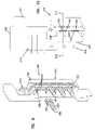
- FIG. 5shows a back perspective view of the cross-connect module of FIG. 2 , the module shown fully assembled
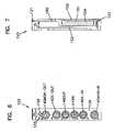
- FIG. 6shows a front view of the cross-connect module of FIG. 2 ;
- FIG. 7shows a back view of the cross-connect module of FIG. 2 ;
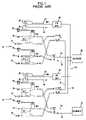
- FIG. 8is a schematic circuit diagram of the cross-connect module of FIG. 2 ;
- FIG. 9shows a circuit board and a DIN-type rear connector mounted on the circuit board in isolation from the cross-connect module of FIG. 2 ;
- FIG. 10shows a partial side view of the circuit board and the DIN-type rear connector of FIG. 9 ;
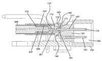
- FIG. 11illustrates a cross sectional view taken along line 11 — 11 of FIG. 10 , showing the termination of a co-axial cable to the DIN-type rear connector.
- FIG. 2illustrates an exploded view of a jack module 120 including examples of how numerous inventive aspects can be practiced.
- the jack module 120includes a housing 122 having a main frame 124 and a cover 125 .
- the main frame 124includes a front end 126 positioned opposite from a rear end 128 .
- a printed circuit board 190i.e., PCB
- the circuit boardprovides two functions. First, the circuit board provides mechanical support for a rear connector 150 (e.g., Eurocard right angle connector or DIN connector) that is mounted adjacent the rear end 128 of the main frame 124 .
- a rear connector 150e.g., Eurocard right angle connector or DIN connector
- the circuit board 190is used to electrically connect tracer light circuitry 130 of the module 120 to a card edge connector 191 .
- the circuit board 190can electrically connect the tracer light circuitry 130 to the connector 150 and/or can be used to route power to the connector 150 .
- the main frame 124 of the module 120includes pockets 132 a , 132 b for respectively receiving jack devices 134 a , 134 b (e.g., jacks as disclosed in U.S. Pat. No. 5,885,096, assigned to ADC Telecommunications, Inc., which is hereby incorporated by reference in its entirety).
- the front end 126 of the main frame 124defines a front face 136 .
- the front face 136defines connector openings 138 corresponding to connector ports 140 MON-OUT, 140 X-OUT, and 140 OUT (collectively referred to with reference number 140 ) of jack device 134 a and connector ports 140 IN, 140 X-IN, and 140 MON-IN (also collectively referred to with reference number 140 ) of jack device 134 b , respectively.
- the jack devices 134 a , 134 bare electrically connected to the rear connector 150 via co-axial cables 200 , as will be described in further detail below.
- the jack devices 134 a , 134 bare not terminated to the printed circuit board, and no digital signals are routed through the printed circuit board. Instead, in each embodiment of the module described herein, the digital signals are routed through the co-axial cables 200 directly from the jacks 134 a , 134 b to the DIN-type rear connector 150 .
- the front face 136 of the main frame 124is adapted for mounting various components of the tracer lamp circuitry.
- the front facedefines openings 137 for receiving leads of light emitting diode (LED) 156 , and an opening 137 ′ for receiving a tracer lamp switch 155 .
- the tracer lamp circuitryis wired to a PCB connector 210 terminated to the circuit board 190 . Tracings of the circuit board 190 electrically connect the PCB connector 210 to the connector 191 .
- the jack module 120includes a housing 122 generally made up of a main frame 124 and a removable cover 125 .
- the cover 125is mounted to the main frame 124 via fasteners 195 that are received within fastener mounts 196 defined on the main frame 124 .
- the cover 125provides an enclosure for the electrical components of the module 120 .
- the top and bottom edges 121 , 123 of the framemay act as guides that are adapted to ride within tracks or grooves defined by a chassis 300 , shown schematically at FIG. 8 , adapted to hold a plurality of modules 120 .
- jack devices 134 a , 134 bare received within pockets 132 a , 132 b , respectively.
- the jack devices 134 a , 134 bare secured to the main frame 124 via fasteners 197 .
- the connector ports 140 of the jack devices 134 a , 134 balign with the openings 138 defined in the front face 136 of the main frame 124 .
- a printed circuit board 190is mounted to the rear end 128 of the main frame 124 via fasteners 198 .
- the rear connector 150is fastened to the printed circuit board via fasteners 199 .
- Cables 200provide the electrical connection between the jack devices 134 a , 134 b and the rear connector 150 .
- the main frame 124also includes cable management structures for organizing the cables 200 in the region between the front jacks 134 a , 134 b and the rear connector 150 .
- a cable guide 146i.e., cable tie-down structure
- the two jack devices 134 a , 134 b of the jack modulepreferably have identical configurations to promote manufacturing efficiency. However, jacks of different configurations could also be used.
- each of the depicted jack devices 134 a , 134 bincludes a jack housing 203 including a front end 202 and a rear end 204 .
- the housing 203can be made from die cast metal.
- the front ends 202 of the jack devices 134 a , 134 bdefine a monitor port 140 MON-OUT or 140 MON-IN, a cross-connect access port 140 X-OUT or 140 X-IN, and an equipment access port 140 OUT or 140 IN.
- the jack devices 134 a , 134 bare received within the pockets 132 a , 132 b defined in the main frame 124 of the module. Once mounted, the ports 140 of the jack devices 134 a , 134 b align with the corresponding connector openings 138 of the front face 136 of the main frame 124 .
- Each jack device 134 a , 134 bincludes switches and other circuit components positioned between the front end 202 and the rear end 204 housed within the housing 203 .
- the rear end 204includes cable termination structures 220 that define connectors 142 . Cables 200 electrically couple the connectors 142 to the rear connector 150 .
- FIG. 8shows a schematic switch configuration for the jack devices 134 a , 134 b of the cross-connect module 120 .
- the schematic for jack device 134 afor example, when no plug is inserted within any of the ports 140 , connectors 142 a and 142 b are electrically connected by springs 222 and 224 .
- the electrical connection between the connectors 142 a and 142 bis broken and a direct electrical connection is provided between port 140 X-OUT and the connector 142 a .
- the center pin of the connector 142 bis grounded.
- the electrical connection between connectors 142 a and 142 bis broken and a direct electrical connection is provided between port 140 OUT and connector 142 b .
- the center pin of the connector 142 ais electrically connected to ground.
- the port 140 MON-OUTallows signals being transferred through the jack device to be non-intrusively monitored.
- the switching circuitry of jack device 134 boperates in the same manner as the switching circuitry of the jack device 134 a.
- the jack module 120is preferably equipped with tracer lamp circuitry 130 .
- the tracer lamp circuitry 130includes a tracer lamp such as a light emitting diode (LED) 156 mounted at the front face 136 of the main frame 124 .
- a tracer lamp switch 155is positioned adjacent the LED 156 .
- the tracer lamp circuitalso includes contact springs 133 a , 133 b , and 133 c (shown in FIG. 2 ) that are press fit within slots 135 defined by a spring mount 139 that is located adjacent the top front corner of the module 120 .
- the contact springs 133 a , 133 b , and 133 care electrically connected to the PCB connector 210 that is mounted to the circuit board at the rear end 128 of the main frame 124 (e.g., via wires 211 shown at FIG. 8 ). As previously described, tracings 213 of the circuit board connect the PCB connector 210 to the connector 191 and/or provide power and ground for the connector 150 .
- Card edge connector 191is adapted to be connected with a power bus of the chassis 300 when the module is inserted into the chassis 300 .
- Contact spring 133 ais also depicted to house an LED flashing arrangement that may include a capacitor, a resistor, and a flashing control circuitry including an integrated circuit (IC) or other means for controlling flashing of the lens.
- a flashing circuitryis optional and can also have a variety of configurations known in the art.
- An example LED flashing arrangementis described in U.S. patent application Ser. No. 10/879,893 entitled PRESS-IN-PLACE LED FOR A DIGITAL SWITCHING CROSS-CONNECT MODULE, assigned to ADC Telecommunications, Inc., the entire disclosure of which is incorporated herein by reference.
- FIG. 8schematically shows the tracer lamp circuit of the jack module 120 .
- the switch 155When the switch 155 is closed, the LED 156 is electrically connected to ground and thereby illuminated. The LED of the module to which the depicted module is cross-connected is also illuminated by closing the switch 155 .
- two jack modules that are cross-connectedcan easily be identified by merely locating the illuminated tracer lamps.
- An example tracer lamp circuitis described in U.S. Pat. No. 6,830,486, assigned to ADC Telecommunications, Inc., the entire disclosure of which is incorporated herein by reference.
- FIG. 8shows the module 120 with the connector 150 mated with a corresponding connector 150 ′ provided at the backplane of a chassis 300 that houses the module 120 .
- the moduleBy interfacing with the backplane of the chassis (e.g., through connectors 150 , 150 ′), the module is connected to equipment 302 and is also cross-connected to another module 304 .
- the connector 191interconnects the tracer light circuitry to corresponding tracer light circuitry of the module 304 , and also connects the tracer light circuitry to power and ground.
- the rear connector 150 of the module 120is depicted as a DIN-type connector (i.e., Eurocard right angle connector).
- the rear connector 150includes an elongated housing 151 having a backwall 153 and sidewalls 152 that define an interior space 154 .
- the housing 151defines a plurality of openings 157 in the backwall 153 that extend through the backwall 153 to the interior space 154 .
- L-shaped prongs 158extend between the circuit board 190 and the openings 157 of the rear connector housing 151 .
- the L-shaped prongs 158are conductive and can be used to establish electrical connection between the circuit board connector 210 and the rear connector 150 (e.g., for power and ground and/or for tracer light connections) through the circuit board 190 .
- Co-axial cables 200are routed from the jack devices 134 a , 134 b directly to the rear connector 150 .
- cable termination at the rear connector 150is provided through a conductive plate 160 structure that includes a plurality of conductive prongs 161 that are inserted into the openings 157 of the connector 150 to form connection pins of the rear connector 150 .
- the plate 160includes a front face 162 , a back face 163 , and a hole 164 extending from the front face 162 to the back face 163 .
- the prongs 161extend forwardly from the front face 162 of the plate 160 and are spaced apart from each other such that they align with the openings 157 of the rear connector 150 .
- the cable 200is connected to the plate 160 through a barrel member 170 (shown in FIG. 2 ) that is mounted at the back face 163 of the plate 160 .
- the barrel 170is generally of elongated shape and is hollow.
- the barrel 170includes a front end 171 and a back end 172 .
- the barrel 170is mechanically coupled to the plate 160 by inserting the front end 171 of the barrel 170 through the hole 164 in the plate 160 and flattening or rolling the front portion 171 of the barrel 170 against the front face 162 of the plate 160 to form an annular retaining flange 171 ′ (see FIG. 11 ).
- the barrel 170is conductive and is electrically connected to the prongs 161 of the plate 160 .
- the cable 200is preferably stripped as shown in FIGS. 2 and 11 .
- the cableincludes an exposed central conductor 201 , a cladding portion 202 surrounding the central conductor 201 , an outer conductive shield 205 surrounding the cladding portion 202 , and an outer insulating jacket 206 surrounding the shield 205 .
- a pin insulator or spacer 173is fitted within the hollow barrel 170 .
- a conductive center pin 175is fitted within the spacer 173 such that the conductive center pin 175 extends through the barrel 170 and out the hole 164 in the plate 160 .
- the center pin 175extends as far as the prongs 161 of the plate 160 and is configured to also form a connection pin of the rear connector 150 .
- the central conductor 201 of the coaxial cable 200is crimped to the center pin 175 by crimp 177 .
- the outer conductive shield 205overlaps and is crimped to the barrel 170 by a crimping ferrule 207 .
- the barrel 170is electrically connected to the prongs 161 of the plate 160 .
- the prongs 161are used to ground the outer conductive shield 205 of the coaxial cable 200 while the central pin 175 is insulated from the barrel 170 by the spacer 173 .
- the front ends of the coaxial cable 200are terminated at the termination structures 220 of the jacks 134 a , 134 b.
- FIGS. 1–11is depicted as a six-port module. It will be appreciated that the inventive aspects of the present disclosure are also applicable to modules having other number of ports (e.g., three-port and four-port modules). Moreover, connectors in accordance with the disclosure can be used in other environments in addition to the cross-connect environment disclosed herein.
Landscapes
- Engineering & Computer Science (AREA)
- Computer Networks & Wireless Communication (AREA)
- Health & Medical Sciences (AREA)
- Toxicology (AREA)
- Details Of Connecting Devices For Male And Female Coupling (AREA)
Abstract
Description
Claims (20)
Priority Applications (2)
| Application Number | Priority Date | Filing Date | Title |
|---|---|---|---|
| US11/241,786US7150656B1 (en) | 2005-09-30 | 2005-09-30 | Digital switching cross-connect module |
| PCT/US2006/037748WO2007041184A1 (en) | 2005-09-30 | 2006-09-26 | Digital switching cross-connect module |
Applications Claiming Priority (1)
| Application Number | Priority Date | Filing Date | Title |
|---|---|---|---|
| US11/241,786US7150656B1 (en) | 2005-09-30 | 2005-09-30 | Digital switching cross-connect module |
Publications (1)
| Publication Number | Publication Date |
|---|---|
| US7150656B1true US7150656B1 (en) | 2006-12-19 |
Family
ID=37526526
Family Applications (1)
| Application Number | Title | Priority Date | Filing Date |
|---|---|---|---|
| US11/241,786Expired - LifetimeUS7150656B1 (en) | 2005-09-30 | 2005-09-30 | Digital switching cross-connect module |
Country Status (2)
| Country | Link |
|---|---|
| US (1) | US7150656B1 (en) |
| WO (1) | WO2007041184A1 (en) |
Cited By (1)
| Publication number | Priority date | Publication date | Assignee | Title |
|---|---|---|---|---|
| US20100202741A1 (en)* | 2009-02-06 | 2010-08-12 | Draka Comteq B.V. | Central-Tube Cable with High-Conductivity Conductors Encapsulated with High-Dielectric-Strength Insulation |
Citations (11)
| Publication number | Priority date | Publication date | Assignee | Title |
|---|---|---|---|---|
| US3474385A (en)* | 1967-06-08 | 1969-10-21 | Ibm | Coaxial cable connector |
| US4815104A (en) | 1988-01-11 | 1989-03-21 | Telect, Inc. | Digital telecommunications network, cross-connect module |
| US5092784A (en)* | 1990-06-18 | 1992-03-03 | Souriau & Cie | Connector component for connecting a coaxial cable to contact pins, and an assembly of such connector components |
| US5209678A (en) | 1992-01-09 | 1993-05-11 | Telect, Inc. | Telecommunications front access coaxial jack and plug assembly with releasable locking feature |
| US5233501A (en) | 1992-02-27 | 1993-08-03 | Telect, Inc. | Digital telecommunication network cross-connect module having a printed circuit board connected to jack switches |
| US5546282A (en) | 1995-05-02 | 1996-08-13 | Telect, Inc. | Telecommunication network digital cross-connect panels having insertable modules with printed circuit board mounted coaxial jack switches |
| US5737309A (en) | 1995-11-09 | 1998-04-07 | Conklin Instrument Corporation | Method and apparatus for interface communications in a tandem cross connect |
| US5744934A (en)* | 1997-05-09 | 1998-04-28 | Formosa Electronic Industries Inc. | Power supply device |
| US5913701A (en) | 1997-02-28 | 1999-06-22 | Adc Telecommunications, Inc. | DSX module with removable switching jack |
| US6729910B2 (en)* | 2001-06-01 | 2004-05-04 | Telect, Inc. | DSX jack LED activation and grounding system |
| US6743032B2 (en) | 1999-04-06 | 2004-06-01 | Adc Telecommunications, Inc. | Digital cross connect module with removable jack |
Family Cites Families (3)
| Publication number | Priority date | Publication date | Assignee | Title |
|---|---|---|---|---|
| DD113136A1 (en)* | 1974-03-26 | 1975-05-12 | ||
| US4770639A (en)* | 1987-03-02 | 1988-09-13 | Switchcraft, Inc. | Channelized jackfield |
| US5170327A (en)* | 1990-11-05 | 1992-12-08 | Adc Telecommunications, Inc. | Distal distribution frame module |
- 2005
- 2005-09-30USUS11/241,786patent/US7150656B1/ennot_activeExpired - Lifetime
- 2006
- 2006-09-26WOPCT/US2006/037748patent/WO2007041184A1/enactiveApplication Filing
Patent Citations (12)
| Publication number | Priority date | Publication date | Assignee | Title |
|---|---|---|---|---|
| US3474385A (en)* | 1967-06-08 | 1969-10-21 | Ibm | Coaxial cable connector |
| US4815104A (en) | 1988-01-11 | 1989-03-21 | Telect, Inc. | Digital telecommunications network, cross-connect module |
| US4815104B1 (en) | 1988-01-11 | 1991-07-02 | Telect Inc | |
| US5092784A (en)* | 1990-06-18 | 1992-03-03 | Souriau & Cie | Connector component for connecting a coaxial cable to contact pins, and an assembly of such connector components |
| US5209678A (en) | 1992-01-09 | 1993-05-11 | Telect, Inc. | Telecommunications front access coaxial jack and plug assembly with releasable locking feature |
| US5233501A (en) | 1992-02-27 | 1993-08-03 | Telect, Inc. | Digital telecommunication network cross-connect module having a printed circuit board connected to jack switches |
| US5546282A (en) | 1995-05-02 | 1996-08-13 | Telect, Inc. | Telecommunication network digital cross-connect panels having insertable modules with printed circuit board mounted coaxial jack switches |
| US5737309A (en) | 1995-11-09 | 1998-04-07 | Conklin Instrument Corporation | Method and apparatus for interface communications in a tandem cross connect |
| US5913701A (en) | 1997-02-28 | 1999-06-22 | Adc Telecommunications, Inc. | DSX module with removable switching jack |
| US5744934A (en)* | 1997-05-09 | 1998-04-28 | Formosa Electronic Industries Inc. | Power supply device |
| US6743032B2 (en) | 1999-04-06 | 2004-06-01 | Adc Telecommunications, Inc. | Digital cross connect module with removable jack |
| US6729910B2 (en)* | 2001-06-01 | 2004-05-04 | Telect, Inc. | DSX jack LED activation and grounding system |
Cited By (2)
| Publication number | Priority date | Publication date | Assignee | Title |
|---|---|---|---|---|
| US20100202741A1 (en)* | 2009-02-06 | 2010-08-12 | Draka Comteq B.V. | Central-Tube Cable with High-Conductivity Conductors Encapsulated with High-Dielectric-Strength Insulation |
| US9360647B2 (en)* | 2009-02-06 | 2016-06-07 | Draka Comteq, B.V. | Central-tube cable with high-conductivity conductors encapsulated with high-dielectric-strength insulation |
Also Published As
| Publication number | Publication date |
|---|---|
| WO2007041184A1 (en) | 2007-04-12 |
Similar Documents
| Publication | Publication Date | Title |
|---|---|---|
| US7524211B2 (en) | Digital switching cross-connect module | |
| EP2078426B1 (en) | Upgradeable patch panel | |
| US6608764B2 (en) | Telecommunications patch panel | |
| US6347963B1 (en) | Interchangeable backplane interface connection panel | |
| US9525255B2 (en) | Low profile faceplate having managed connectivity | |
| US20030022559A1 (en) | Jack; jack assembly; and methods | |
| US9437990B2 (en) | Managed electrical connectivity systems | |
| CA2572768C (en) | Long frame high density patching system | |
| EP2224546B1 (en) | Cassette having interchangeable rear mating connectors | |
| US6830487B2 (en) | Pin jack for a digital switching cross-connect module | |
| US7150656B1 (en) | Digital switching cross-connect module | |
| US7182502B2 (en) | Press-in place LED for a digital switching cross-connect module | |
| CN100591146C (en) | DSX Module with Performance Monitoring | |
| US7239699B2 (en) | Monitor network for a digital switching cross-connect module |
Legal Events
| Date | Code | Title | Description |
|---|---|---|---|
| AS | Assignment | Owner name:ADC TELECOMMUNICATIONS, INC., MINNESOTA Free format text:ASSIGNMENT OF ASSIGNORS INTEREST;ASSIGNORS:BAKER, SCOTT K.;PETERSEN, CYLE D.;REEL/FRAME:017143/0163 Effective date:20051027 | |
| STCF | Information on status: patent grant | Free format text:PATENTED CASE | |
| FPAY | Fee payment | Year of fee payment:4 | |
| FPAY | Fee payment | Year of fee payment:8 | |
| AS | Assignment | Owner name:TYCO ELECTRONICS SERVICES GMBH, SWITZERLAND Free format text:ASSIGNMENT OF ASSIGNORS INTEREST;ASSIGNOR:ADC TELECOMMUNICATIONS, INC.;REEL/FRAME:036060/0174 Effective date:20110930 | |
| AS | Assignment | Owner name:COMMSCOPE EMEA LIMITED, IRELAND Free format text:ASSIGNMENT OF ASSIGNORS INTEREST;ASSIGNOR:TYCO ELECTRONICS SERVICES GMBH;REEL/FRAME:036956/0001 Effective date:20150828 | |
| AS | Assignment | Owner name:COMMSCOPE TECHNOLOGIES LLC, NORTH CAROLINA Free format text:ASSIGNMENT OF ASSIGNORS INTEREST;ASSIGNOR:COMMSCOPE EMEA LIMITED;REEL/FRAME:037012/0001 Effective date:20150828 | |
| AS | Assignment | Owner name:JPMORGAN CHASE BANK, N.A., AS COLLATERAL AGENT, ILLINOIS Free format text:PATENT SECURITY AGREEMENT (TERM);ASSIGNOR:COMMSCOPE TECHNOLOGIES LLC;REEL/FRAME:037513/0709 Effective date:20151220 Owner name:JPMORGAN CHASE BANK, N.A., AS COLLATERAL AGENT, ILLINOIS Free format text:PATENT SECURITY AGREEMENT (ABL);ASSIGNOR:COMMSCOPE TECHNOLOGIES LLC;REEL/FRAME:037514/0196 Effective date:20151220 Owner name:JPMORGAN CHASE BANK, N.A., AS COLLATERAL AGENT, IL Free format text:PATENT SECURITY AGREEMENT (ABL);ASSIGNOR:COMMSCOPE TECHNOLOGIES LLC;REEL/FRAME:037514/0196 Effective date:20151220 Owner name:JPMORGAN CHASE BANK, N.A., AS COLLATERAL AGENT, IL Free format text:PATENT SECURITY AGREEMENT (TERM);ASSIGNOR:COMMSCOPE TECHNOLOGIES LLC;REEL/FRAME:037513/0709 Effective date:20151220 | |
| MAFP | Maintenance fee payment | Free format text:PAYMENT OF MAINTENANCE FEE, 12TH YEAR, LARGE ENTITY (ORIGINAL EVENT CODE: M1553) Year of fee payment:12 | |
| AS | Assignment | Owner name:ANDREW LLC, NORTH CAROLINA Free format text:RELEASE BY SECURED PARTY;ASSIGNOR:JPMORGAN CHASE BANK, N.A.;REEL/FRAME:048840/0001 Effective date:20190404 Owner name:ALLEN TELECOM LLC, ILLINOIS Free format text:RELEASE BY SECURED PARTY;ASSIGNOR:JPMORGAN CHASE BANK, N.A.;REEL/FRAME:048840/0001 Effective date:20190404 Owner name:REDWOOD SYSTEMS, INC., NORTH CAROLINA Free format text:RELEASE BY SECURED PARTY;ASSIGNOR:JPMORGAN CHASE BANK, N.A.;REEL/FRAME:048840/0001 Effective date:20190404 Owner name:COMMSCOPE, INC. OF NORTH CAROLINA, NORTH CAROLINA Free format text:RELEASE BY SECURED PARTY;ASSIGNOR:JPMORGAN CHASE BANK, N.A.;REEL/FRAME:048840/0001 Effective date:20190404 Owner name:COMMSCOPE TECHNOLOGIES LLC, NORTH CAROLINA Free format text:RELEASE BY SECURED PARTY;ASSIGNOR:JPMORGAN CHASE BANK, N.A.;REEL/FRAME:048840/0001 Effective date:20190404 Owner name:COMMSCOPE, INC. OF NORTH CAROLINA, NORTH CAROLINA Free format text:RELEASE BY SECURED PARTY;ASSIGNOR:JPMORGAN CHASE BANK, N.A.;REEL/FRAME:049260/0001 Effective date:20190404 Owner name:ALLEN TELECOM LLC, ILLINOIS Free format text:RELEASE BY SECURED PARTY;ASSIGNOR:JPMORGAN CHASE BANK, N.A.;REEL/FRAME:049260/0001 Effective date:20190404 Owner name:COMMSCOPE TECHNOLOGIES LLC, NORTH CAROLINA Free format text:RELEASE BY SECURED PARTY;ASSIGNOR:JPMORGAN CHASE BANK, N.A.;REEL/FRAME:049260/0001 Effective date:20190404 Owner name:REDWOOD SYSTEMS, INC., NORTH CAROLINA Free format text:RELEASE BY SECURED PARTY;ASSIGNOR:JPMORGAN CHASE BANK, N.A.;REEL/FRAME:049260/0001 Effective date:20190404 Owner name:ANDREW LLC, NORTH CAROLINA Free format text:RELEASE BY SECURED PARTY;ASSIGNOR:JPMORGAN CHASE BANK, N.A.;REEL/FRAME:049260/0001 Effective date:20190404 | |
| AS | Assignment | Owner name:JPMORGAN CHASE BANK, N.A., NEW YORK Free format text:ABL SECURITY AGREEMENT;ASSIGNORS:COMMSCOPE, INC. OF NORTH CAROLINA;COMMSCOPE TECHNOLOGIES LLC;ARRIS ENTERPRISES LLC;AND OTHERS;REEL/FRAME:049892/0396 Effective date:20190404 Owner name:WILMINGTON TRUST, NATIONAL ASSOCIATION, AS COLLATE Free format text:PATENT SECURITY AGREEMENT;ASSIGNOR:COMMSCOPE TECHNOLOGIES LLC;REEL/FRAME:049892/0051 Effective date:20190404 Owner name:JPMORGAN CHASE BANK, N.A., NEW YORK Free format text:TERM LOAN SECURITY AGREEMENT;ASSIGNORS:COMMSCOPE, INC. OF NORTH CAROLINA;COMMSCOPE TECHNOLOGIES LLC;ARRIS ENTERPRISES LLC;AND OTHERS;REEL/FRAME:049905/0504 Effective date:20190404 Owner name:WILMINGTON TRUST, NATIONAL ASSOCIATION, AS COLLATERAL AGENT, CONNECTICUT Free format text:PATENT SECURITY AGREEMENT;ASSIGNOR:COMMSCOPE TECHNOLOGIES LLC;REEL/FRAME:049892/0051 Effective date:20190404 | |
| AS | Assignment | Owner name:WILMINGTON TRUST, DELAWARE Free format text:SECURITY INTEREST;ASSIGNORS:ARRIS SOLUTIONS, INC.;ARRIS ENTERPRISES LLC;COMMSCOPE TECHNOLOGIES LLC;AND OTHERS;REEL/FRAME:060752/0001 Effective date:20211115 | |
| AS | Assignment | Owner name:APOLLO ADMINISTRATIVE AGENCY LLC, NEW YORK Free format text:SECURITY INTEREST;ASSIGNORS:ARRIS ENTERPRISES LLC;COMMSCOPE TECHNOLOGIES LLC;COMMSCOPE INC., OF NORTH CAROLINA;AND OTHERS;REEL/FRAME:069889/0114 Effective date:20241217 | |
| AS | Assignment | Owner name:RUCKUS WIRELESS, LLC (F/K/A RUCKUS WIRELESS, INC.), NORTH CAROLINA Free format text:RELEASE OF SECURITY INTEREST AT REEL/FRAME 049905/0504;ASSIGNOR:JPMORGAN CHASE BANK, N.A., AS COLLATERAL AGENT;REEL/FRAME:071477/0255 Effective date:20241217 Owner name:COMMSCOPE TECHNOLOGIES LLC, NORTH CAROLINA Free format text:RELEASE OF SECURITY INTEREST AT REEL/FRAME 049905/0504;ASSIGNOR:JPMORGAN CHASE BANK, N.A., AS COLLATERAL AGENT;REEL/FRAME:071477/0255 Effective date:20241217 Owner name:COMMSCOPE, INC. OF NORTH CAROLINA, NORTH CAROLINA Free format text:RELEASE OF SECURITY INTEREST AT REEL/FRAME 049905/0504;ASSIGNOR:JPMORGAN CHASE BANK, N.A., AS COLLATERAL AGENT;REEL/FRAME:071477/0255 Effective date:20241217 Owner name:ARRIS SOLUTIONS, INC., NORTH CAROLINA Free format text:RELEASE OF SECURITY INTEREST AT REEL/FRAME 049905/0504;ASSIGNOR:JPMORGAN CHASE BANK, N.A., AS COLLATERAL AGENT;REEL/FRAME:071477/0255 Effective date:20241217 Owner name:ARRIS TECHNOLOGY, INC., NORTH CAROLINA Free format text:RELEASE OF SECURITY INTEREST AT REEL/FRAME 049905/0504;ASSIGNOR:JPMORGAN CHASE BANK, N.A., AS COLLATERAL AGENT;REEL/FRAME:071477/0255 Effective date:20241217 Owner name:ARRIS ENTERPRISES LLC (F/K/A ARRIS ENTERPRISES, INC.), NORTH CAROLINA Free format text:RELEASE OF SECURITY INTEREST AT REEL/FRAME 049905/0504;ASSIGNOR:JPMORGAN CHASE BANK, N.A., AS COLLATERAL AGENT;REEL/FRAME:071477/0255 Effective date:20241217 |