US7150416B2 - Liquid fuel injection - Google Patents
Liquid fuel injectionDownload PDFInfo
- Publication number
- US7150416B2 US7150416B2US10/821,641US82164104AUS7150416B2US 7150416 B2US7150416 B2US 7150416B2US 82164104 AUS82164104 AUS 82164104AUS 7150416 B2US7150416 B2US 7150416B2
- Authority
- US
- United States
- Prior art keywords
- fuel
- nozzle
- schrader valve
- liquid fuel
- purge gas
- Prior art date
- Legal status (The legal status is an assumption and is not a legal conclusion. Google has not performed a legal analysis and makes no representation as to the accuracy of the status listed.)
- Expired - Fee Related, expires
Links
Images


Classifications
- F—MECHANICAL ENGINEERING; LIGHTING; HEATING; WEAPONS; BLASTING
- F23—COMBUSTION APPARATUS; COMBUSTION PROCESSES
- F23D—BURNERS
- F23D11/00—Burners using a direct spraying action of liquid droplets or vaporised liquid into the combustion space
- F23D11/24—Burners using a direct spraying action of liquid droplets or vaporised liquid into the combustion space by pressurisation of the fuel before a nozzle through which it is sprayed by a substantial pressure reduction into a space
- F—MECHANICAL ENGINEERING; LIGHTING; HEATING; WEAPONS; BLASTING
- F23—COMBUSTION APPARATUS; COMBUSTION PROCESSES
- F23D—BURNERS
- F23D11/00—Burners using a direct spraying action of liquid droplets or vaporised liquid into the combustion space
- F23D11/36—Details
- F23D11/38—Nozzles; Cleaning devices therefor
- F23D11/386—Nozzle cleaning
- F—MECHANICAL ENGINEERING; LIGHTING; HEATING; WEAPONS; BLASTING
- F23—COMBUSTION APPARATUS; COMBUSTION PROCESSES
- F23D—BURNERS
- F23D2209/00—Safety arrangements
- F23D2209/30—Purging
- Y—GENERAL TAGGING OF NEW TECHNOLOGICAL DEVELOPMENTS; GENERAL TAGGING OF CROSS-SECTIONAL TECHNOLOGIES SPANNING OVER SEVERAL SECTIONS OF THE IPC; TECHNICAL SUBJECTS COVERED BY FORMER USPC CROSS-REFERENCE ART COLLECTIONS [XRACs] AND DIGESTS
- Y10—TECHNICAL SUBJECTS COVERED BY FORMER USPC
- Y10T—TECHNICAL SUBJECTS COVERED BY FORMER US CLASSIFICATION
- Y10T137/00—Fluid handling
- Y10T137/4238—With cleaner, lubrication added to fluid or liquid sealing at valve interface
- Y10T137/4245—Cleaning or steam sterilizing
- Y10T137/4259—With separate material addition
- Y—GENERAL TAGGING OF NEW TECHNOLOGICAL DEVELOPMENTS; GENERAL TAGGING OF CROSS-SECTIONAL TECHNOLOGIES SPANNING OVER SEVERAL SECTIONS OF THE IPC; TECHNICAL SUBJECTS COVERED BY FORMER USPC CROSS-REFERENCE ART COLLECTIONS [XRACs] AND DIGESTS
- Y10—TECHNICAL SUBJECTS COVERED BY FORMER USPC
- Y10T—TECHNICAL SUBJECTS COVERED BY FORMER US CLASSIFICATION
- Y10T137/00—Fluid handling
- Y10T137/8593—Systems
- Y10T137/87571—Multiple inlet with single outlet
- Y10T137/87676—With flow control
- Y10T137/87684—Valve in each inlet
Definitions
- the present inventiongenerally relates to fuel injection technology. More specifically, the present invention relates to improved liquid fuel injection technology that can be advantageously utilized to inject hydrocarbon fuels into hot gases.
- the chloride method for producing titanium dioxide(“TiO 2 ”) consists of reacting preheated oxygen gas with titanium tetrachloride (“TiCl 4 ”) gas to produce TiO 2 particles. Additives in small amounts can be used to control the particle size and structure. Hydrocarbon fuel can be added to the preheated oxygen to increase its temperature further to a final oxygen temperature of about 3000° F. to about 3800° F. prior to the reaction with titanium tetrachloride vapor. The use of supplemental hydrocarbon fuel eliminates the need to build a hot oxygen supply system that can withstand the elevated temperatures that are required.
- Hydrocarbon fuels either in the vapor phase or in the liquid phasecan be used to increase the oxygen temperature to its final temperature during the TiO 2 production process.
- advantages to using hydrocarbon fuels in the liquid phaseinclude, for example, a safer means to deliver the fuel to the reaction zone, the use of low-grade, less costly fuel, and the ability to deliver additives to the reaction zone in a consistent manner by dissolving the additives in the fuel.
- the present inventionprovides for liquid fuel injectors that allow the injection of a fine spray of liquid fuel.
- Liquid fuel injectors of the present inventionutilize a schrader valve movable between an open position and a closed position. When the schrader valve is in the closed position fuel flow is blocked and purge gas is allowed to flow through the fuel injectors. When the schrader valve is in the open position, the flow of purge gas is blocked and fuel is allowed to flow through the fuel injector. In this manner, the fuel injectors of the present invention provide for an immediate and automatic purge of the fuel lines when the fuel flow is shut off.
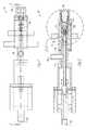
- FIG. 1illustrates a top-down view of a fuel injector of the present invention in the closed position.
- FIG. 2illustrates a cross-sectional view of the fuel injector shown in FIG. 1 .
- FIG. 3illustrates an enlarged view of a portion of the fuel injector shown in FIG. 1 and FIG. 2 .
- FIG. 4illustrates the fuel injector of FIG. 3 in the open position.
- FIG. 5shows a cut-away view of the fuel injector of FIG. 1–4 .
- Fuel injectors of the present inventioncomprise a nozzle; a purge gas inlet; a liquid fuel inlet; and a schrader valve, movable between an open position and a closed position, wherein the liquid fuel inlet is in communication with the nozzle when the schrader valve is in the open position and the purge gas inlet is not in communication with the nozzle when the schrader valve is in the open position, and wherein the liquid fuel inlet is not in communication with the nozzle when the schrader valve is in the closed position and the purge gas inlet is in communication with the nozzle when the schrader valve is in the closed position.
- the fuel injectorWhen the schrader valve is in the open position, the fuel injector is said to be on or open. Similarly, when the schrader valve is in the closed position, the fuel injector is said to be off or closed.
- the liquid fuel inletintroduces liquid fuel into the fuel injector and the purge gas inlet introduces purge gas into the fuel injector.
- the schrader valveWhen the schrader valve is in an open position, the liquid fuel inlet is in communication with the nozzle and the purge gas inlet is not in communication with the nozzle. That is, when the liquid fuel inlet is in communication with the nozzle, the liquid fuel can flow from the liquid fuel inlet to the nozzle. The liquid fluid will then flow through the nozzle, which causes the liquid fuel to spray into a reaction chamber.
- the purge gas inletis not in communication with the nozzle, the purge gas is blocked from flowing to the nozzle from the purge gas inlet.
- the schrader valveWhen the schrader valve is in a closed position, the purge gas inlet is in communication with the nozzle and the liquid fuel inlet is not in communication with the nozzle.
- the schrader valveis moving from either the closed position to the open position or from the open position to the closed position, there may be brief moments when neither the liquid fuel nor the purge gas is flowing.
- the schrader valveis in the closed position, blocking the liquid fuel from flowing to the nozzle and allowing the purge gas to flow to the nozzle.
- the flow of purge gas through the fuel injector and through the nozzleeffectively cleans the fuel line, preventing carbon from blocking the fuel line or nozzle.
- the flow of purge gascan also help cool the fuel injector, including the nozzle.
- the schrader valveis moved to the open position, blocking the flow of purge gas to the nozzle and allowing the flow of liquid fuel to the nozzle.
- the fuel injectoris turned off by moving the schrader valve into the closed position, stopping the flow of fuel, and immediately allowing the flow of purge gas.
- FIG. 1shows a top-down view of a fuel injector 100 according to the present invention.
- the fuel injector 100comprises a nozzle 102 , a purge gas inlet 104 , a liquid fuel inlet 106 , and a schrader valve 108 .
- Nozzles known in the artmay be advantageously used in fuel injectors of the present invention.
- fuel injectors according to the present inventioncan be produced using nozzles available from Wm. Steinen Manufacturing Company.
- Schrader valvesare also known in the industry. Schrader valves are a type of valve fitting that opens when depressed.
- Schrader valvesare known to be used in tire valve stems, on air conditioning hoses, and on the fuel rails of some fuel injection systems. Fuel injectors of the present invention can be produced using Schrader valves available from Schrader Bridgeport, Inc., for example.
- FIG. 2shows a cross-sectional view of the fuel injector 100 of FIG. 1 .
- the schrader valve 108is in the closed position.
- Purge gasenters the fuel injector 100 through the purge gas inlet 104 and flows into the space 110 between the fuel tube 116 and the casing 118 of the fuel injector 100 .
- the purge gaspasses through the space 110 between the fuel tube 116 and the casing 118 of the fuel injector 100 and continues through a space between the fuel tube 116 and the valve seat 112 , the purge gas then continuing into the space 114 between the schrader valve 108 and the nozzle 102 and then passing through the nozzle 102 into a reaction chamber (not shown).
- FIG. 3shows an enlarged view of the nozzle end of the fuel injector 100 shown in FIG. 1 and FIG. 2 .
- the schrader valve 108is positioned inside the fuel tube 116 and at the end of the fuel tube 116 nearest the nozzle 102 .
- One manner of positioning the schrader valve 108 into the fuel tube 116is simply to screw the schrader valve 108 into the end of the fuel tube 116 .
- the internal radius of the valve seat 112is about three one-hundredths (0.03) of an inch larger than the external radius of the fuel tube 116 . While the schrader valve 108 is in the closed position, the spring 120 helps maintain the valve seat 112 away from the nozzle.
- the fuel tube 116As the fuel injector 100 is turned on or opened, the fuel tube 116 is pushed toward the nozzle 102 . As the fuel tube 116 moves forward, the protrusion 122 on the fuel tube 116 contacts the valve seat 112 . The contact of the protrusion 122 on the fuel tube 116 with the valve seat 112 closes the pathway for the purge gas, effectively shutting off the purge gas. When the protrusion 122 on the fuel tube 116 is in contact with the valve seat 112 , the stem 124 of the schrader valve 108 will protrude from the valve seat 112 .
- protrudingit is meant that the distance from stem 124 of the schrader valve 108 to the nozzle 102 is less than the distance from the valve seat 112 to the nozzle 102 .
- the fuel tube 116pushes the valve seat 112 toward the nozzle 102 , depressing the spring 120 .
- the fuel tube 116continues forward, contacting the schrader valve stem 124 with the nozzle 102 .
- the fuel tube 116continues forward, depressing the schrader valve stem 124 .
- the schrader valve stem 124is depressed the schrader valve 108 is open and fuel is allowed to flow into the fuel tube from the fuel inlet 106 (shown in FIG. 1 and FIG. 2 ) through the fuel tube 116 , through the schrader valve 108 , and through the nozzle 102 into a reaction chamber (not shown).
- FIG. 4shows the fuel injector 100 of FIG. 3 with the schrader valve 108 in the open position.
- the protrusion 122 on the fuel tube 116is in contact with the valve seat 112 and the valve seat 112 has been pushed forward (to the right in FIG. 4 ), depressing the spring 120 and depressing the valve stem 124 by virtue of the valve stem's 124 contact with the nozzle 102 .
- the schrader valve 108is open and fuel is allowed to flow from the fuel tube 116 , through the schrader valve 108 , and through the nozzle 102 into a reaction chamber (not shown). The fuel continues to flow through the nozzle 102 into the reaction chamber (not shown) until the fuel injector 100 is shut off or closed.
- FIGS. 1–5do not illustrate the precise flow path that the fuel or purge gas takes when passing through the nozzle 102 .
- the precise flow path through nozzles used in fuel injectors of the present inventionis not a critical aspect of the present invention and may vary depending on the specific type or brand of nozzle used.
- the fuel injector 100is shut off or closed by retracting the fuel tube.
- the fuel tube 116is retracted, allowing the spring 120 to push the valve seat 112 back to its closed position as the fuel tube 116 is retracted.
- the schrader valve 108is retracted the schrader valve stem 124 is no longer depressed and the schrader valve 108 closes, shutting off the flow of liquid fuel.
- the fuel tubecontinues to retract until the valve seat 112 reaches its closed position, at which point the valve seat 112 is blocked from retracting further.
- the fuel tube 116continues to be retracted a little further so that the protrusion 122 on the fuel tube 116 is no longer in contact with the valve seat 112 , thereby allowing purge gas to flow between the schrader valve 108 and the valve seat 112 and through the nozzle 102 , purging the liquid fuel from the fuel injector 100 .
- the fuel injector 100is a preferred embodiment of the present invention in that the schrader valve stem 124 is depressed, thereby opening the schrader valve 108 , by pressing the stem 124 against the nozzle 102 .
- Thisplaces the schrader valve 108 in close proximity to the nozzle 102 when the schrader valve 108 is opened. Consequently, the volume of the space between the schrader valve 108 and the nozzle 102 is very small and this space can contain only a small amount of fuel.
- the schrader valve 108is moved to the closed position, only a small amount of fuel needs to be purged, and therefore, the fuel can be purged quickly. This is an advantage over fuel injectors of the prior art, as fuel injectors of the prior art can take several seconds to purge relatively large amounts of fuel.
- Fuel injectors of the present inventioncould use other means for depressing the schrader valve stem.
- fuel injectors of the present inventioncould utilize an alternate structure to depress the schrader valve stem.
- the alternate structurecan be placed near the nozzle such that the stem contacts the alternate structure instead of the nozzle.
- This alternate structurecould be made of a material more durable than the nozzle and save wear and tear on the nozzle.
- Any appropriate meanscan be employed to move or push the fuel tube toward the nozzle when moving the schrader valve from the closed position to the open position.
- One preferred methodis to allow the pressure in the liquid fuel line to push the fuel tube toward the nozzle, moving the schrader valve from the closed position to the open position.
- a fuel valvecan be used, as is known in the art, to open the fuel line leading to the fuel injector, creating a pressure in the fuel line sufficient to push the fuel tube toward the nozzle and move the schrader valve to the open position.
- Another preferred methodutilizes an air cylinder to both extend the fuel tube toward the nozzle, moving the schrader valve to the open position, and retract the fuel tube, moving the schrader valve to the closed position.
- the portion of the fuel injector that protrudes into the reaction chamber or the furnaceis typically covered by a heat shield to protect the internal parts of the fuel injector from excessive heat.
- Heat shieldsare known in the art and fuel injectors of the present invention can be advantageously utilized in conjunction with heat shields known in the art.
- the portion of the fuel injector 100 that protrudes into the reaction chamber(not shown) is covered by a heat shield 128 .
- Fuel injectors of the present inventionmay also comprise a casing that forms a chamber adapted to have a suitable coolant circulated there through. Such casings and their corresponding chambers are frequently referred to as cooling jackets.
- the cooling jacketis referred to as a cooling water jacket.
- Cooling jackets suitable for use with fuel injectors of the present inventionare known in the art.
- the casing 130houses cooling water baffles 132 adapted to have a suitable coolant circulated there-through.
- FIG. 5illustrates the position of a cooling water inlet 134 and a cooling water exit 136 as well as one of the cooling water baffles 132 . Water enters the cooling water inlet 134 , absorbs heat while traveling through the cooling water baffles 132 , and then exits through the cooling water exit 136 .
- the heat shieldwill conduct heat into a cooling water jacket.
- fuel injectors of the present inventionare used to spray hydrocarbon fuel into a reaction chamber where the fuel reacts with preheated oxygen, generating sufficient heat to raise the temperature of excess unreacted oxygen to a temperature of about 3000° F. to about 3800° F. The heated oxygen is then reacted with titanium tetrachloride to produce titanium dioxide.
- preferred hydrocarbon fuelsinclude toluene, propane, and blends thereof.
- Preferred purge gasesinclude nitrogen and air.
- the fuel injectorscomprise a purge mechanism that causes a virtually immediate and automatic purge of the fuel lines when the fuel is shut off.
Landscapes
- Engineering & Computer Science (AREA)
- Chemical & Material Sciences (AREA)
- Combustion & Propulsion (AREA)
- Mechanical Engineering (AREA)
- General Engineering & Computer Science (AREA)
- Fuel-Injection Apparatus (AREA)
- Fuel Cell (AREA)
Abstract
Description
Claims (5)
Priority Applications (9)
| Application Number | Priority Date | Filing Date | Title |
|---|---|---|---|
| US10/821,641US7150416B2 (en) | 2004-04-09 | 2004-04-09 | Liquid fuel injection |
| CNB2005800122192ACN100565012C (en) | 2004-04-09 | 2005-03-23 | Use the liquid fuel injector and the method thereof of purified gas |
| CA 2562540CA2562540A1 (en) | 2004-04-09 | 2005-03-23 | Liquid fuel injection with purge air |
| PCT/US2005/009784WO2005103567A1 (en) | 2004-04-09 | 2005-03-23 | Liquid fuel injection with purge air |
| EP05731479AEP1733170B1 (en) | 2004-04-09 | 2005-03-23 | Liquid fuel injection with purge air |
| AU2005236428AAU2005236428B2 (en) | 2004-04-09 | 2005-03-23 | Liquid fuel injection with purge air |
| RU2006138662/06ARU2006138662A (en) | 2004-04-09 | 2005-03-23 | LIQUID FUEL INJECTION WITH A BLOW AIR |
| DE200560007588DE602005007588D1 (en) | 2004-04-09 | 2005-03-23 | LIQUID FUEL INJECTION WITH RINSING AIR |
| TW94109849ATW200535332A (en) | 2004-04-09 | 2005-03-29 | Liquid fuel injection |
Applications Claiming Priority (1)
| Application Number | Priority Date | Filing Date | Title |
|---|---|---|---|
| US10/821,641US7150416B2 (en) | 2004-04-09 | 2004-04-09 | Liquid fuel injection |
Publications (2)
| Publication Number | Publication Date |
|---|---|
| US20060144954A1 US20060144954A1 (en) | 2006-07-06 |
| US7150416B2true US7150416B2 (en) | 2006-12-19 |
Family
ID=34964259
Family Applications (1)
| Application Number | Title | Priority Date | Filing Date |
|---|---|---|---|
| US10/821,641Expired - Fee RelatedUS7150416B2 (en) | 2004-04-09 | 2004-04-09 | Liquid fuel injection |
Country Status (9)
| Country | Link |
|---|---|
| US (1) | US7150416B2 (en) |
| EP (1) | EP1733170B1 (en) |
| CN (1) | CN100565012C (en) |
| AU (1) | AU2005236428B2 (en) |
| CA (1) | CA2562540A1 (en) |
| DE (1) | DE602005007588D1 (en) |
| RU (1) | RU2006138662A (en) |
| TW (1) | TW200535332A (en) |
| WO (1) | WO2005103567A1 (en) |
Cited By (16)
| Publication number | Priority date | Publication date | Assignee | Title |
|---|---|---|---|---|
| US20080209897A1 (en)* | 2007-03-02 | 2008-09-04 | Caterpillar Inc. | Fluid injector having purge heater |
| US8943833B2 (en) | 2012-07-06 | 2015-02-03 | United Technologies Corporation | Fuel flexible fuel injector |
| US9080540B2 (en) | 2010-08-11 | 2015-07-14 | Cummins Inc. | Engine with injector mounting and cooling arrangement |
| US9441836B2 (en) | 2012-07-10 | 2016-09-13 | United Technologies Corporation | Fuel-air pre-mixer with prefilmer |
| US11201379B2 (en) | 2017-06-15 | 2021-12-14 | Lg Chem, Ltd. | Secondary battery having filling valve |
| US11613003B2 (en) | 2020-01-24 | 2023-03-28 | General Electric Company | Line assembly for an extension tool having a plurality of links |
| US11654547B2 (en) | 2021-03-31 | 2023-05-23 | General Electric Company | Extension tool |
| US11692650B2 (en) | 2020-01-23 | 2023-07-04 | General Electric Company | Selectively flexible extension tool |
| US11702955B2 (en) | 2019-01-14 | 2023-07-18 | General Electric Company | Component repair system and method |
| US11707819B2 (en) | 2018-10-15 | 2023-07-25 | General Electric Company | Selectively flexible extension tool |
| US11752622B2 (en) | 2020-01-23 | 2023-09-12 | General Electric Company | Extension tool having a plurality of links |
| US11834990B2 (en) | 2020-03-10 | 2023-12-05 | Oliver Crispin Robotics Limited | Insertion tool |
| US12091981B2 (en) | 2020-06-11 | 2024-09-17 | General Electric Company | Insertion tool and method |
| US12194620B2 (en) | 2018-10-15 | 2025-01-14 | Oliver Crisipin Robotics Limited | Selectively flexible extension tool |
| US12405187B2 (en) | 2019-10-04 | 2025-09-02 | General Electric Company | Insertion apparatus for use with rotary machines |
| US12416800B2 (en) | 2021-01-08 | 2025-09-16 | General Electric Company | Insertion tool |
Citations (15)
| Publication number | Priority date | Publication date | Assignee | Title |
|---|---|---|---|---|
| US2488439A (en) | 1946-03-09 | 1949-11-15 | Du Pont | Production of titanium oxide pigments |
| US3213918A (en) | 1963-09-04 | 1965-10-26 | Bethlehem Steel Corp | Liquid-gaseous fuel burner |
| US3381896A (en) | 1965-09-24 | 1968-05-07 | Ray Oil Burner Co | System for purging nozzles in dual fuel burners |
| US3561726A (en) | 1969-02-18 | 1971-02-09 | Frank M Iannelli | Plastic coupling |
| US3791412A (en)* | 1972-06-05 | 1974-02-12 | H Mays | Reducing valve for high pressure fluids and connecting means therefor |
| US4439400A (en) | 1980-09-12 | 1984-03-27 | Phillips Petroleum Company | Apparatus for producing carbon black |
| US4784841A (en) | 1986-10-31 | 1988-11-15 | Kronos Titan, Gmbh | Process for the production of coarse, scrubbing aggregates of titanium dioxide particles by oxidation of titanium tetrachloride in the vapor phase and use of said aggregates for the prevention of deposit formation in the same production process |
| US5370527A (en) | 1992-10-28 | 1994-12-06 | The Coleman Company, Inc. | Fuel tube for burner assembly with remote fuel tank |
| US5599519A (en) | 1992-08-10 | 1997-02-04 | Tioxide Group Services Limited | Oxidation of titanium tetrachloride to form titanium dioxide |
| US5823221A (en) | 1995-03-03 | 1998-10-20 | Paul Wurth S.A. | Device and method for the automatic coupling of a teeming ladle to one or more gas pipes |
| US5840112A (en) | 1996-07-25 | 1998-11-24 | Kerr Mcgee Chemical Corporation | Method and apparatus for producing titanium dioxide |
| US6035837A (en) | 1998-11-06 | 2000-03-14 | Siemens Automotive Corporation | Bi-fuel liquid injection system for an internal combustion engine |
| US6116896A (en)* | 1999-09-15 | 2000-09-12 | Air Liquide America Inc. | System and method for oxidant injection in rotary kilns |
| US6269840B1 (en)* | 1996-12-10 | 2001-08-07 | American Standard International Inc. | Valve-in-valve body, vent port and method |
| US6539970B1 (en)* | 1999-10-21 | 2003-04-01 | Prime Solutions, Llc | Method and apparatus for servicing a pressurized system |
Family Cites Families (3)
| Publication number | Priority date | Publication date | Assignee | Title |
|---|---|---|---|---|
| CH293288A (en)* | 1951-08-09 | 1953-09-15 | Oelfeuerungen Ag | Flushing device for nozzle line and nozzle of oil burners. |
| US4191214A (en)* | 1978-07-07 | 1980-03-04 | Forney Engineering Company | Sequential operating mechanism for valves |
| JPS60164627A (en)* | 1984-02-06 | 1985-08-27 | Hitachi Ltd | Fuel nozzle purge system |
- 2004
- 2004-04-09USUS10/821,641patent/US7150416B2/ennot_activeExpired - Fee Related
- 2005
- 2005-03-23WOPCT/US2005/009784patent/WO2005103567A1/enactiveApplication Filing
- 2005-03-23AUAU2005236428Apatent/AU2005236428B2/ennot_activeCeased
- 2005-03-23DEDE200560007588patent/DE602005007588D1/ennot_activeExpired - Lifetime
- 2005-03-23CNCNB2005800122192Apatent/CN100565012C/ennot_activeExpired - Fee Related
- 2005-03-23CACA 2562540patent/CA2562540A1/ennot_activeAbandoned
- 2005-03-23RURU2006138662/06Apatent/RU2006138662A/ennot_activeApplication Discontinuation
- 2005-03-23EPEP05731479Apatent/EP1733170B1/ennot_activeExpired - Lifetime
- 2005-03-29TWTW94109849Apatent/TW200535332A/enunknown
Patent Citations (16)
| Publication number | Priority date | Publication date | Assignee | Title |
|---|---|---|---|---|
| US2488439A (en) | 1946-03-09 | 1949-11-15 | Du Pont | Production of titanium oxide pigments |
| US3213918A (en) | 1963-09-04 | 1965-10-26 | Bethlehem Steel Corp | Liquid-gaseous fuel burner |
| US3381896A (en) | 1965-09-24 | 1968-05-07 | Ray Oil Burner Co | System for purging nozzles in dual fuel burners |
| US3561726A (en) | 1969-02-18 | 1971-02-09 | Frank M Iannelli | Plastic coupling |
| US3791412A (en)* | 1972-06-05 | 1974-02-12 | H Mays | Reducing valve for high pressure fluids and connecting means therefor |
| US4439400A (en) | 1980-09-12 | 1984-03-27 | Phillips Petroleum Company | Apparatus for producing carbon black |
| US4784841A (en) | 1986-10-31 | 1988-11-15 | Kronos Titan, Gmbh | Process for the production of coarse, scrubbing aggregates of titanium dioxide particles by oxidation of titanium tetrachloride in the vapor phase and use of said aggregates for the prevention of deposit formation in the same production process |
| US5599519A (en) | 1992-08-10 | 1997-02-04 | Tioxide Group Services Limited | Oxidation of titanium tetrachloride to form titanium dioxide |
| US5370527A (en) | 1992-10-28 | 1994-12-06 | The Coleman Company, Inc. | Fuel tube for burner assembly with remote fuel tank |
| US5823221A (en) | 1995-03-03 | 1998-10-20 | Paul Wurth S.A. | Device and method for the automatic coupling of a teeming ladle to one or more gas pipes |
| US5840112A (en) | 1996-07-25 | 1998-11-24 | Kerr Mcgee Chemical Corporation | Method and apparatus for producing titanium dioxide |
| US6207131B1 (en) | 1996-07-25 | 2001-03-27 | Kerr-Mcgee Chemical Llc | Method and apparatus for producing titanium dioxide |
| US6269840B1 (en)* | 1996-12-10 | 2001-08-07 | American Standard International Inc. | Valve-in-valve body, vent port and method |
| US6035837A (en) | 1998-11-06 | 2000-03-14 | Siemens Automotive Corporation | Bi-fuel liquid injection system for an internal combustion engine |
| US6116896A (en)* | 1999-09-15 | 2000-09-12 | Air Liquide America Inc. | System and method for oxidant injection in rotary kilns |
| US6539970B1 (en)* | 1999-10-21 | 2003-04-01 | Prime Solutions, Llc | Method and apparatus for servicing a pressurized system |
Cited By (18)
| Publication number | Priority date | Publication date | Assignee | Title |
|---|---|---|---|---|
| US8484947B2 (en)* | 2007-03-02 | 2013-07-16 | Caterpillar Inc. | Fluid injector having purge heater |
| US20080209897A1 (en)* | 2007-03-02 | 2008-09-04 | Caterpillar Inc. | Fluid injector having purge heater |
| US9080540B2 (en) | 2010-08-11 | 2015-07-14 | Cummins Inc. | Engine with injector mounting and cooling arrangement |
| US8943833B2 (en) | 2012-07-06 | 2015-02-03 | United Technologies Corporation | Fuel flexible fuel injector |
| US9441836B2 (en) | 2012-07-10 | 2016-09-13 | United Technologies Corporation | Fuel-air pre-mixer with prefilmer |
| US11201379B2 (en) | 2017-06-15 | 2021-12-14 | Lg Chem, Ltd. | Secondary battery having filling valve |
| US12194620B2 (en) | 2018-10-15 | 2025-01-14 | Oliver Crisipin Robotics Limited | Selectively flexible extension tool |
| US11707819B2 (en) | 2018-10-15 | 2023-07-25 | General Electric Company | Selectively flexible extension tool |
| US12264591B2 (en) | 2019-01-14 | 2025-04-01 | General Electric Company | Component repair system and method |
| US11702955B2 (en) | 2019-01-14 | 2023-07-18 | General Electric Company | Component repair system and method |
| US12405187B2 (en) | 2019-10-04 | 2025-09-02 | General Electric Company | Insertion apparatus for use with rotary machines |
| US11692650B2 (en) | 2020-01-23 | 2023-07-04 | General Electric Company | Selectively flexible extension tool |
| US11752622B2 (en) | 2020-01-23 | 2023-09-12 | General Electric Company | Extension tool having a plurality of links |
| US11613003B2 (en) | 2020-01-24 | 2023-03-28 | General Electric Company | Line assembly for an extension tool having a plurality of links |
| US11834990B2 (en) | 2020-03-10 | 2023-12-05 | Oliver Crispin Robotics Limited | Insertion tool |
| US12091981B2 (en) | 2020-06-11 | 2024-09-17 | General Electric Company | Insertion tool and method |
| US12416800B2 (en) | 2021-01-08 | 2025-09-16 | General Electric Company | Insertion tool |
| US11654547B2 (en) | 2021-03-31 | 2023-05-23 | General Electric Company | Extension tool |
Also Published As
| Publication number | Publication date |
|---|---|
| CN1946967A (en) | 2007-04-11 |
| CA2562540A1 (en) | 2005-11-03 |
| TW200535332A (en) | 2005-11-01 |
| CN100565012C (en) | 2009-12-02 |
| AU2005236428B2 (en) | 2010-07-08 |
| WO2005103567A1 (en) | 2005-11-03 |
| EP1733170B1 (en) | 2008-06-18 |
| RU2006138662A (en) | 2008-05-20 |
| US20060144954A1 (en) | 2006-07-06 |
| DE602005007588D1 (en) | 2008-07-31 |
| EP1733170A1 (en) | 2006-12-20 |
| AU2005236428A1 (en) | 2005-11-03 |
Similar Documents
| Publication | Publication Date | Title |
|---|---|---|
| US7150416B2 (en) | Liquid fuel injection | |
| US8826883B2 (en) | Gas engine | |
| US8015816B2 (en) | Apparatus for discouraging fuel from entering the heat shield air cavity of a fuel injector | |
| US4166830A (en) | Diacritic cracking of hydrocarbon feeds for selective production of ethylene and synthesis gas | |
| TWI494436B (en) | Tuyere stock arrangement of a blast furnace | |
| US4124353A (en) | Method and apparatus for carrying out a reaction between streams of fluid | |
| KR20090059115A (en) | Liquid Material Vaporizer | |
| CA1048395A (en) | Method and apparatus for carrying out a reaction between streams of fluid | |
| US3540821A (en) | Flue gas recirculation burner | |
| JP7651990B2 (en) | Combustor and reformer | |
| MXPA06011564A (en) | Liquid fuel injection with purge air | |
| KR20130028896A (en) | Apparatus and method for forming amorphous coating film | |
| TWI384184B (en) | Diffusion combustion burner | |
| EP4212475B1 (en) | Oxygen injection system for a direct reduction process | |
| KR102112668B1 (en) | Rocket engine with wall cooling device and rocket engine having the same | |
| US7717703B2 (en) | Combustion head for use with a flame spray apparatus | |
| US20080085485A1 (en) | Method Of Combustion With The Aid Of Burners In Industrial Furnaces,And A Burner To This End | |
| TWI843066B (en) | Gas reduction material injection method and tuyere for blast furnace | |
| KR101462096B1 (en) | Combustor | |
| KR20170009332A (en) | Ship engine exhaust gas handling system | |
| JP2004101083A (en) | Gasification furnace and burner | |
| RU1836434C (en) | Sealing unit of blast furnace lock chamber | |
| US3937449A (en) | Liquid-fuel atomization and injection device | |
| JP2005003360A (en) | Tubular flame burner | |
| JPH0979044A (en) | Gas turbine nozzle purge method |
Legal Events
| Date | Code | Title | Description |
|---|---|---|---|
| AS | Assignment | Owner name:KERR-MCGEE CHEMICAL, LLC, OKLAHOMA Free format text:ASSIGNMENT OF ASSIGNORS INTEREST;ASSIGNORS:MARTIN, ROBERT O.;FLYNN, HARRY EUGENE;NATALIE, CHARLES A.;REEL/FRAME:014903/0278 Effective date:20040713 | |
| AS | Assignment | Owner name:LEHMAN COMMERCIAL PAPER INC., NEW YORK Free format text:SECURITY AGREEMENT;ASSIGNOR:TRONOX LLC F/K/A KERR-MCGEE CHEMICAL LLC;REEL/FRAME:021411/0792 Effective date:20080814 | |
| FEPP | Fee payment procedure | Free format text:PAYOR NUMBER ASSIGNED (ORIGINAL EVENT CODE: ASPN); ENTITY STATUS OF PATENT OWNER: LARGE ENTITY | |
| FPAY | Fee payment | Year of fee payment:4 | |
| AS | Assignment | Owner name:GOLDMAN SACHS LENDING PARTNERS LLC, AS COLLATERAL Free format text:SECURITY AGREEMENT;ASSIGNOR:TRONOX LLC;REEL/FRAME:025795/0130 Effective date:20110214 | |
| AS | Assignment | Owner name:WELLS FARGO CAPITAL FINANCE, LLC, AS AGENT, ILLINO Free format text:SECURITY AGREEMENT;ASSIGNORS:TRONOX LLC;TRONOX PIGMENTS (SAVANNAH) INC.;REEL/FRAME:025822/0026 Effective date:20110214 | |
| AS | Assignment | Owner name:TRONOX LLC, OKLAHOMA Free format text:BANKRUPTCY COURT NOTICE CONFIRMING RELEASE OF LIENS EFFECTIVE 2/14/2011;ASSIGNOR:LEHMAN COMMERCIAL PAPER, INC.;REEL/FRAME:026010/0684 Effective date:20110215 | |
| AS | Assignment | Owner name:TRONOX LLC, OKLAHOMA Free format text:RELEASE BY SECURED PARTY;ASSIGNOR:GOLDMAN SACHS LENDING PARTNERS LLC;REEL/FRAME:027682/0064 Effective date:20120208 Owner name:GOLDMAN SACHS BANK USA, AS COLLATERAL AGENT, NEW Y Free format text:SECURITY AGREEMENT;ASSIGNOR:TRONOX LLC;REEL/FRAME:027682/0086 Effective date:20120208 | |
| AS | Assignment | Owner name:TRONOX WORLDWIDE LLC, OKLAHOMA Free format text:RELEASE OF SECURITY INTEREST IN PATENTS;ASSIGNOR:WELLS FARGO CAPITAL FINANCE, LLC;REEL/FRAME:028535/0362 Effective date:20120618 Owner name:TRONOX LLC, OKLAHOMA Free format text:RELEASE OF SECURITY INTEREST IN PATENTS;ASSIGNOR:WELLS FARGO CAPITAL FINANCE, LLC;REEL/FRAME:028535/0362 Effective date:20120618 | |
| AS | Assignment | Owner name:UBS AG, STAMFORD BRANCH, CONNECTICUT Free format text:PATENT SECURITY AGREEMENT;ASSIGNORS:TRONOX LLC;TRONOX WORLDWIDE LLC;REEL/FRAME:028582/0669 Effective date:20120618 | |
| REMI | Maintenance fee reminder mailed | ||
| LAPS | Lapse for failure to pay maintenance fees | ||
| STCH | Information on status: patent discontinuation | Free format text:PATENT EXPIRED DUE TO NONPAYMENT OF MAINTENANCE FEES UNDER 37 CFR 1.362 | |
| FP | Lapsed due to failure to pay maintenance fee | Effective date:20141219 | |
| AS | Assignment | Owner name:TRONOX LLC, CONNECTICUT Free format text:RELEASE OF SECURITY INTEREST IN PATENTS;ASSIGNOR:UBS AG, STAMFORD BRANCH, AS COLLATERAL AGENT;REEL/FRAME:043993/0306 Effective date:20170922 Owner name:TRONOX WORLDWIDE LLC, CONNECTICUT Free format text:RELEASE OF SECURITY INTEREST IN PATENTS;ASSIGNOR:UBS AG, STAMFORD BRANCH, AS COLLATERAL AGENT;REEL/FRAME:043993/0306 Effective date:20170922 Owner name:WELLS FARGO BANK, NATIONAL ASSOCIATION, NEW YORK Free format text:SECURITY INTEREST;ASSIGNOR:TRONOX LLC;REEL/FRAME:043993/0340 Effective date:20170922 | |
| AS | Assignment | Owner name:TRONOX LLC, OKLAHOMA Free format text:RELEASE OF SECURITY INTEREST IN INTELLECTUAL PROPERTY COLLATERAL AT REEL/FRAME NOS. 027682/0086 AND 030047/0422;ASSIGNOR:GOLDMAN SACHS BANK USA, AS COLLATERAL AGENT;REEL/FRAME:044018/0893 Effective date:20170922 | |
| AS | Assignment | Owner name:BANK OF AMERICA, N.A., AS COLLATERAL AGENT, ILLINO Free format text:PATENT SECURITY AGREEMENT;ASSIGNOR:TRONOX LLC;REEL/FRAME:044100/0339 Effective date:20170922 | |
| AS | Assignment | Owner name:HSBC BANK USA, NATIONAL ASSOCIATION, AS THE SUCCESSOR ADMINISTRATIVE AGENT AND COLLATERAL AGENT, NEW YORK Free format text:ASSIGNMENT OF SECURITY INTEREST IN PATENT COLLATERAL RECORDED AT REEL/FRAME 044100/0339;ASSIGNOR:BANK OF AMERICA, N.A.;REEL/FRAME:055578/0880 Effective date:20210311 Owner name:TRONOX LLC, CONNECTICUT Free format text:RELEASE BY SECURED PARTY;ASSIGNOR:WELLS FARGO BANK, NATIONAL ASSOCIATION;REEL/FRAME:055583/0001 Effective date:20210311 |