US7150190B2 - Method and apparatus for capacitively determining the uppermost level of a liquid in a container - Google Patents
Method and apparatus for capacitively determining the uppermost level of a liquid in a containerDownload PDFInfo
- Publication number
- US7150190B2 US7150190B2US11/085,660US8566005AUS7150190B2US 7150190 B2US7150190 B2US 7150190B2US 8566005 AUS8566005 AUS 8566005AUS 7150190 B2US7150190 B2US 7150190B2
- Authority
- US
- United States
- Prior art keywords
- liquid
- sensor
- charging time
- charging
- network
- Prior art date
- Legal status (The legal status is an assumption and is not a legal conclusion. Google has not performed a legal analysis and makes no representation as to the accuracy of the status listed.)
- Expired - Lifetime, expires
Links
Images


Classifications
- G—PHYSICS
- G01—MEASURING; TESTING
- G01F—MEASURING VOLUME, VOLUME FLOW, MASS FLOW OR LIQUID LEVEL; METERING BY VOLUME
- G01F23/00—Indicating or measuring liquid level or level of fluent solid material, e.g. indicating in terms of volume or indicating by means of an alarm
- G01F23/22—Indicating or measuring liquid level or level of fluent solid material, e.g. indicating in terms of volume or indicating by means of an alarm by measuring physical variables, other than linear dimensions, pressure or weight, dependent on the level to be measured, e.g. by difference of heat transfer of steam or water
- G01F23/26—Indicating or measuring liquid level or level of fluent solid material, e.g. indicating in terms of volume or indicating by means of an alarm by measuring physical variables, other than linear dimensions, pressure or weight, dependent on the level to be measured, e.g. by difference of heat transfer of steam or water by measuring variations of capacity or inductance of capacitors or inductors arising from the presence of liquid or fluent solid material in the electric or electromagnetic fields
- G01F23/263—Indicating or measuring liquid level or level of fluent solid material, e.g. indicating in terms of volume or indicating by means of an alarm by measuring physical variables, other than linear dimensions, pressure or weight, dependent on the level to be measured, e.g. by difference of heat transfer of steam or water by measuring variations of capacity or inductance of capacitors or inductors arising from the presence of liquid or fluent solid material in the electric or electromagnetic fields by measuring variations in capacitance of capacitors
- G01F23/266—Indicating or measuring liquid level or level of fluent solid material, e.g. indicating in terms of volume or indicating by means of an alarm by measuring physical variables, other than linear dimensions, pressure or weight, dependent on the level to be measured, e.g. by difference of heat transfer of steam or water by measuring variations of capacity or inductance of capacitors or inductors arising from the presence of liquid or fluent solid material in the electric or electromagnetic fields by measuring variations in capacitance of capacitors measuring circuits therefor
- G—PHYSICS
- G01—MEASURING; TESTING
- G01F—MEASURING VOLUME, VOLUME FLOW, MASS FLOW OR LIQUID LEVEL; METERING BY VOLUME
- G01F25/00—Testing or calibration of apparatus for measuring volume, volume flow or liquid level or for metering by volume
- G01F25/20—Testing or calibration of apparatus for measuring volume, volume flow or liquid level or for metering by volume of apparatus for measuring liquid level
- G01F25/24—Testing proper functioning of electronic circuits
- G—PHYSICS
- G01—MEASURING; TESTING
- G01N—INVESTIGATING OR ANALYSING MATERIALS BY DETERMINING THEIR CHEMICAL OR PHYSICAL PROPERTIES
- G01N35/00—Automatic analysis not limited to methods or materials provided for in any single one of groups G01N1/00 - G01N33/00; Handling materials therefor
- G01N35/10—Devices for transferring samples or any liquids to, in, or from, the analysis apparatus, e.g. suction devices, injection devices
- G01N35/1009—Characterised by arrangements for controlling the aspiration or dispense of liquids
- G01N2035/1025—Fluid level sensing
Definitions
- the present inventionrelates to a method and apparatus for aspirating liquid samples, reagents, or other solutions from a container using a probe.
- the present inventionprovides a method for determining the uppermost level of liquid within the container so that a precisely predetermined volume of liquid may be aspirated from the container into the probe.
- Various types of analytical tests related to patient diagnosis and therapycan be performed by analysis of a liquid sample taken from a patient's infections, bodily fluids or abscesses. These assays are typically conducted with automated clinical analyzers onto which tubes or vials containing patient samples have been loaded. The analyzer extracts a pre-determined volume of liquid sample, typically in the range of 1–3 mL, from the vial using an appropriate probe and combines the sample with various reagents in special reaction cuvettes. Analytical measurements are often performed using a beam of interrogating radiation interacting with the sample-reagent combination, for example turbidimetric, fluorometric, absorption readings or the like. The measurements allow determination of end-point or reaction rate values from which an amount of analyte related to the health of the patient may be determined.
- An important aspect of maintaining analytical accuracy in such analyzersis the ability to precisely extract the pre-determined volume of liquid sample from the vial.
- the probeis introduced into the liquid container and preferably maintained a short distance below the surface of the liquid. Liquid aspiration is then accomplished by either aspirating the pre-determined volume while the probe is stationary (for very small volumes) or moving the probe further into the probe during aspiration (for larger volumes).
- U.S. Pat. No. 6,164,132discloses a capacitive liquid level sensor having a capacitive sensor array superposed on each side of a dielectric substrate, wherein the sensor signal detection electronics are located immediately adjacent each capacitive sensor. These provisions result in high sensitivity of detection of submergence in the liquid, as well as essentially eliminating parasitic electric fields.
- the preferred capacitive sensorsare interdigitated capacitors, and the preferred sensor signal detection circuit is an RC bridge and a comparator.
- the sensitivity of the capacitive liquid level sensorallows a reference capacitive sensor to be obviated, so that there are no false indications of liquid level due to any film of the liquid clinging to an exposed portion of the capacitive liquid level sensor.
- U.S. Pat. No. 5,493,922discloses a liquid level sensor control circuit for controlling the position of a sampling probe relative to a liquid in a container.
- the apparatusincludes a sampling probe, an oscillator circuit coupled to the sampling probe for producing a first output signal having a constant frequency, a comparator coupled to the oscillator circuit for comparing the amplitude of the first output signal to a first reference amplitude and for producing a change signal when the amplitude of the first output signal changes with respect to the reference amplitude, and a controller responsive to the change signal for controlling the position of the sampling probe with respect to the surface of the liquid.
- U.S. Pat. No. 5,437,184discloses a capacitive liquid level sensor having phase detecting circuitry in a capacitive sensor array.
- An X-OR circuitgenerates a first logic level signal when a difference in the phase of two signals from any two adjacent output plates indicates that a phase difference is present.
- a second logic signalis generated if no phase difference is detected.
- the signalsare perfectly in phase when any two adjacent output plates are either submerged in fluid or both disposed in air.
- U.S. Pat. No. 5,365,783discloses a computer controlled pipette probe for aspirating or dispensing liquid in the vessel.
- the charge developed via the capacitance on the probeis coupled to a capacitive sensor circuit which provides a peak detector with an amplified signal representing the peak capacitance between the probe and the liquid.
- This amplified signalis detected by a peak-capacitance discrimination circuit, the output of which is monitored by the computer for determining the precise position of the probe with respect to the liquid surface level.
- U.S. Pat. No. 5,083,470minimizes false level sensing problems associated with capacitive liquid level sensors by isolating the probe from the connecting tubing by the use of an element exhibiting inductive reactance.
- U.S. Pat. No. 6,101,873having a plurality of electrodes positioned vertically from the liquid surface and a level detection circuit for detecting level of the liquid by measuring variations of the capacitance measured between the electrodes
- U.S. Pat. No. 5,600,997wherein a capacitive probe is located at a predetermined desired fluid detection level and when the fluid level recedes, the capacitance of the system changes
- U.S. Pat. No. 5,451,940having a measuring capacitance and at least one reference capacitor
- the principal object of the inventionis to provide an improved method for confirming that a change in capacitance within a liquid level sensor is caused only by true physical contact between a probe and a liquid.
- the present inventionverifies that any change in capacitance of the liquid level sensor is repeatable and constant over a given time period and thereby is caused by actual contact the probe and liquid and is not caused by spurious electrical disturbances or other measuring irregularities.
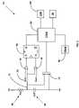
- FIG. 1is a schematic plan view of an automated analyzer in which the present invention may be advantageously employed
- FIG. 2is a block diagram of the liquid level sensor of the present invention
- FIG. 3is a schematic representation of the liquid level sensor of the present invention.
- FIG. 4is a block diagram of the liquid sensor of the present invention with a probe submerged in liquid;
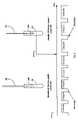
- FIG. 5is a timing diagram for the liquid level sensor of the present invention.
- FIG. 1shows schematically the elements of an automatic chemical analyzer 10 in which the present invention may be advantageously practiced, analyzer 10 comprising a reaction carousel 12 supporting an outer carousel 14 having cuvette ports 20 formed therein and an inner carousel 16 having vessel ports 22 formed therein, the outer carousel 14 and inner carousel 16 being separated by a open groove 18 .
- Cuvette ports 20are adapted to receive a plurality of reaction cuvettes that contain various reagents and sample liquids for conventional clinical and immunoassay assays while vessel ports 22 are adapted to receive a plurality of reaction vessels that contain specialized reagents for ultra-high sensitivity immunoassays.
- Reaction carousel 12is rotatable using stepwise movements in a constant direction, the stepwise movements being separated by a constant dwell time during which reaction carousel 12 is maintained stationary and computer controlled assay operational devices 24 , such as measuring devices 28 , sensors, reagent add stations, mixing stations and the like, operate as needed on an assay mixture contained within a reaction cuvette or vessel.
- assay operational devices 24such as measuring devices 28 , sensors, reagent add stations, mixing stations and the like, operate as needed on an assay mixture contained within a reaction cuvette or vessel.
- Analyzer 10is controlled by software executed by the computer 26 based on computer programs written in a machine language like that used on the Dimension® clinical chemistry analyzer sold by Dade Behring Inc, of Deerfield, Ill., and widely used by those skilled in the art of computer-based electromechanical control programming.
- FIG. 1shows a bi-directional incoming and outgoing sample fluid tube transport system 30 comprises a mechanism for transporting sample fluid tube racks 32 containing open or closed sample fluid containers such as sample fluid tubes 34 from a rack input load position at a first end of the input lane 35 to the second end of input lane 35 as indicated by open arrow 35 A.
- Liquid specimens contained in sample tubes 34are identified by reading bar coded indicia placed thereon using a conventional bar code reader to determine, among other items, a patient's identity, tests to be performed, if a sample aliquot is to be retained within analyzer 10 and if so, for what period of time.
- a liquid aspiration probe 36is located proximate the second end of the input lane 35 and is operable to aspirate aliquot portions of sample fluid from sample fluid tubes 34 and to dispense an aliquot portion of the sample fluid into one or more of a plurality of vessels 38 in aliquot vessel array 40 , maintained in aliquot vessel array transport system 42 , depending on the quantity of sample fluid required to perform the requisite assays and to provide for a sample fluid aliquot to be retained by analyzer 10 within an environmental chamber.
- rack 32may be moved, as indicated by open arrow 36 A, to a front area of analyzer 10 and unloaded from analyzer 10 .
- Temperature-controlled storage areas or servers 44 and 46inventory a plurality of multi-compartment elongate reagent cartridges 48 containing reagents accessible by aspiration probes 50 and 52 as necessary to perform clinical assays on sample aliquots removed from sample tubes 34 and dispensed into aliquot vessels 38 .
- analyzer 10During operation of analyzer 10 using the devices illustrated in FIG. 1 , there are several instances when it is critical to aspirate a pre-determined amount of a liquid or liquid solution, for example, from sample tube 34 or reagent container 48 , using aspiration probes 36 and 50 , respectively. Aspiration may be advantageously accomplished using, for example, the sample aspiration method disclosed in co-pending U.S. patent application Ser. No. 10/871,409. An important aspect of aspirating such liquids is the ability to precisely and accurately ascertain the uppermost level of liquid in said container and a number of methods exist in the art for completing this task.
- FIG. 2illustrates probe 36 as being vertically moveable over sample tube 34 , indicated by arrow 36 A, so that a needle portion 56 of probe 36 may be lowered into contact with the uppermost level 34 L of a sample liquid 35 contained in tube 34 .
- Aspiration probe 36is connected to a piston-like pump 58 through a vent valve 60 by means of tubing 62 , pump 58 being operable to aspirate and dispense liquid in response to signals from computer 26 .
- a capacitive liquid level sensor 64is formed by means of an applied voltage Va applied through a known fixed resistor Rrc 66 to needle 56 thereby effectively forming an RC network because of an effective capacitance Ceff 68 formed between needle 56 and liquid 35 within tube 34 .
- An electrical measuring networkconsisting of a window comparator 54 comprising a pair of operational amplifiers 76 , a flip-flop 80 , CPLD 82 and DSP 84 , described hereinafter, is adapted to compare the voltage in effective capacitance 68 of the RC network to a reference voltage as probe 56 is lowered towards liquid 35 , thereby defining capacitive liquid level sensor 64 .
- the voltage in effective capacitance 68will remain essentially constant because of the air gap between probe 56 and the uppermost level 34 L of liquid 35 until probe 56 physically contacts the uppermost level 34 L of liquid 35 , at which instance the voltage in effective capacitance 68 will increase sharply.
- the present inventionis an improvement over prior art sensors that may be adversely affected by the presence of foam, bubbles or other surface irregularities in that the present capacitive liquid level sensor 64 repeatedly measures the amount of time required for the voltage in effective capacitance 68 to charge to a reference value, averages that amount of charging time over a number of successive readings, and identifies any change in the averaged charging time that exceeds a pre-determined value.
- Another problem with known capacitive liquid level measuring systemsis dependence upon the sensitivity of the electronic circuitry for monitoring the change in voltage level. If this sensitivity is too low or drifts over time, the sensed voltage level change will be skewed and the system will be unable to accurately compare the change in voltage level to a threshold reference level.
- An even further problem with such capacitive liquid level measuring systemsis that the sensed RC voltage level may not reach the threshold reference level when tube 34 contains very small amounts of liquid. Systems using a fixed threshold level are not useful in such instances, and systems with a variable threshold level require an undesirable calibration process.
- the present inventionavoids problems like these encountered in the prior art by confirming that the previously identified change in the averaged charging time is stable over a pre-determined time period, and rejects as invalid any changes in the averaged charging time that are not stable over the previously identified pre-determined time period.
- the present inventionachieves these improvements using a time-based voltage measuring circuit like that illustrated in FIG. 3 wherein is shown a block diagram of the functional theory of operation for the liquid level sensor 64 .
- the basic premise of this circuitis based on the charging of unknown external capacitance Ceff 68 of needle 56 .
- the liquid level sensor 64 of the present inventionconsists of known fixed resistor Rrc 66 and unknown external capacitance Ceff 68 of needle 56 , the measured voltage 72 of which is applied to a set of comparators 76 , for example operational amplifiers 76 .
- a reference voltage Vref 74is applied to comparators 76 .
- the voltage of the RC network portion of liquid level sensor 64is set to 0 volts using a Field Effect Transistor FET latch 78 to discharge the RC network capacitance to ground. Since the RC network voltage 72 is less than Vref 74 , the set of comparators 76 causes the output of a flip-flop 80 to send a high state signal to a Complex Programmable Logic Device CPLD 82 . CPLD 82 is programmed to then turn FET 78 off causing two things to happen:
- the two comparators 76When the voltage of the RC network applied to the two comparators 76 is slightly greater than Vref 74 , the two comparators 76 set flip-flop 80 to the low state of CPLD 82 .
- the low transitioncauses programming within CPLD 82 to:
- a “Read Done” signalis sent to CPLD 82 which causes FET latch 78 to be released, grounding the capacitance Ceff 68 of needle 56 , and interrupting the count signal from counter 86 going to DSP 84 .
- This charging-discharging-recharging processis continuously repeated with DSP 84 reading each successive time interval required for capacitance Ceff 68 to charge to Vref 74 .
- FIG. 5This change to a relatively higher count value when needle 56 penetrates the uppermost level 34 L of a sample liquid 35 is shown in FIG. 5 in which C 1 count represents the periods of time in discharge-charge cycles of the capacitance Ceff 68 of needle 56 while needle 56 is above the uppermost level 34 L of a sample liquid 35 .
- C 2 countrepresents the periods of time in discharge-charge cycles of the capacitance Ceff 68 of needle 56 while needle 56 is below the uppermost level 34 L of a sample liquid 35 .
- the sensitivity of liquid level sensor 64is established by empirically predetermining the number of counts that C 2 count is higher than C 1 count when needle 56 penetrates the uppermost level 34 L of a sample liquid 35 .
- DSP 84is employed to make this comparison between C 2 count as measured relative to C 1 count.
- C 2 countis about 33% higher than C 1 count whereas in practice the increase will be much smaller, in the order of 2–5% for a highly sensitive liquid level sensor 64 .
- a key factor in the present inventionis further using DSP 84 to calculate a running average of counts made by counter 86 over a number of discharge-charge cycles in order to verify that any change in counts between discharge-charge cycles is a persistent change and is therefore not caused by false signals arising from factors such as foam, bubbles, electrical disturbances and the like but is the result of actual penetration of liquid level 34 L by needle 56 .
- the number of discharge-charge cycles to be averagedmay be varied depending upon the nature of the aspiration process but generally a number in the range of 3 to 7 cycles has been found to be sufficient for the aspiration of patient liquid samples.
- Verification that the higher counts between discharge-charge cycles is persistent, and is not a false trigger,can be accomplished by simply interrogating DSP 84 to confirm that the higher count level has been maintained. It is this verification that can be established by predetermining the sensitivity of the liquid level sensor 64 that is an improvement over prior art sensors.
- the effective capacitance of needle 56may cause counter 86 to read in the range of 10,000 to 10,020 counts.
- the countmay abruptly change to 10,200 counts because of the increase in effective capacitance of needle 56 . If the sensitivity of the circuitry of liquid level sensor 64 was selected to be 180 counts, then penetration of liquid level 34 L by needle 56 would be detected.
- computer 26may readily be adapted to receiving any change in the averaged charging time from signal processor 84 and be programmed to maintain needle 56 below the uppermost level 34 L of a liquid in response to any change in the averaged charging time.
Landscapes
- Physics & Mathematics (AREA)
- Engineering & Computer Science (AREA)
- General Physics & Mathematics (AREA)
- Power Engineering (AREA)
- Fluid Mechanics (AREA)
- Thermal Sciences (AREA)
- Electromagnetism (AREA)
- Life Sciences & Earth Sciences (AREA)
- General Health & Medical Sciences (AREA)
- Immunology (AREA)
- Pathology (AREA)
- Biochemistry (AREA)
- Analytical Chemistry (AREA)
- Chemical & Material Sciences (AREA)
- Health & Medical Sciences (AREA)
- Measurement Of Levels Of Liquids Or Fluent Solid Materials (AREA)
- Automatic Analysis And Handling Materials Therefor (AREA)
Abstract
Description
Vref=Va(1−e−time/RC) Formula 1
- 1. The voltage to the two
comparators 76 will begin to rise exponentially. - 2. A
Counter 86, typically comprising a 100 MHz clock and a latch, is enabled to count and begins counting.
- 1. The voltage to the two
- 1. Latch the time count, thus determining the time to reach
Vref 74; - 2. Send an interrupt to a Digital
Signal Processor DSP 84 to read the count; and, - 3. Turn on the discharge signal to
FET 78 for a fixed time to discharge the voltage of the RC network.
- 1. Latch the time count, thus determining the time to reach
Claims (8)
Priority Applications (2)
| Application Number | Priority Date | Filing Date | Title |
|---|---|---|---|
| US11/085,660US7150190B2 (en) | 2005-03-21 | 2005-03-21 | Method and apparatus for capacitively determining the uppermost level of a liquid in a container |
| PCT/US2006/009924WO2006102186A2 (en) | 2005-03-21 | 2006-03-20 | Method and apparatus for capacitively determining the uppermost level of a liquid in a container |
Applications Claiming Priority (1)
| Application Number | Priority Date | Filing Date | Title |
|---|---|---|---|
| US11/085,660US7150190B2 (en) | 2005-03-21 | 2005-03-21 | Method and apparatus for capacitively determining the uppermost level of a liquid in a container |
Publications (2)
| Publication Number | Publication Date |
|---|---|
| US20060207322A1 US20060207322A1 (en) | 2006-09-21 |
| US7150190B2true US7150190B2 (en) | 2006-12-19 |
Family
ID=37008899
Family Applications (1)
| Application Number | Title | Priority Date | Filing Date |
|---|---|---|---|
| US11/085,660Expired - LifetimeUS7150190B2 (en) | 2005-03-21 | 2005-03-21 | Method and apparatus for capacitively determining the uppermost level of a liquid in a container |
Country Status (2)
| Country | Link |
|---|---|
| US (1) | US7150190B2 (en) |
| WO (1) | WO2006102186A2 (en) |
Cited By (26)
| Publication number | Priority date | Publication date | Assignee | Title |
|---|---|---|---|---|
| US20070143063A1 (en)* | 2005-12-19 | 2007-06-21 | Michael Kaplit | Method for ascertaining interferants in small liquid samples in an automated clinical analyzer |
| US20070240505A1 (en)* | 2006-04-12 | 2007-10-18 | Charles Cammarata | Fluid level detector and analyzer |
| US20090069756A1 (en)* | 2006-03-20 | 2009-03-12 | Novo Nordisk A/S | Determination of Cartridge Content by Capacitive Means |
| US20110061415A1 (en)* | 2005-03-25 | 2011-03-17 | Charles Barry Ward | Condensate Pump |
| US20110085917A1 (en)* | 2005-03-25 | 2011-04-14 | Charles Barry Ward | Condensate Pump |
| WO2011062982A1 (en) | 2009-11-20 | 2011-05-26 | Siemens Healthcare Diagnostics Inc. | Apparatus, systems, and methods adapted to rinse and dry clinical analyzer sample probes |
| US7985375B2 (en) | 2007-04-06 | 2011-07-26 | Qiagen Gaithersburg, Inc. | Sample preparation system and method for processing clinical specimens |
| US20110192017A1 (en)* | 2008-09-30 | 2011-08-11 | Endress +Hauser Gmbh + Co. Kg | Method for manufacturing a capacitive measuring apparatus |
| WO2012032318A1 (en) | 2010-09-09 | 2012-03-15 | Randox Laboratories Ltd. | Capacitive liquid level sensor |
| WO2012106042A1 (en)* | 2011-01-31 | 2012-08-09 | Xylem Ip Holdings Llc | Ultrasonic water level gauge and control device |
| US20120290227A1 (en)* | 2011-05-13 | 2012-11-15 | Itt Manufacturing Enterprises, Inc. | Level sensing |
| EP2607905A1 (en) | 2011-12-23 | 2013-06-26 | F. Hoffmann-La Roche AG | Method and system for discriminating bulk liquid from foam and residuals of the bulk liquid |
| WO2014055590A1 (en) | 2012-10-04 | 2014-04-10 | Siemens Healthcare Diagnostics Inc. | Methods and apparatus for measuring aspiration pressure at low aspiration volumes |
| US8703492B2 (en) | 2007-04-06 | 2014-04-22 | Qiagen Gaithersburg, Inc. | Open platform hybrid manual-automated sample processing system |
| EP2741087A1 (en) | 2012-12-04 | 2014-06-11 | F. Hoffmann-La Roche AG | Method and system for fluid surface detection |
| WO2015057868A1 (en) | 2013-10-17 | 2015-04-23 | Siemens Healthcare Diagnostics Inc. | Methods and apparatus for measuring aspiration pressure |
| WO2015066342A1 (en) | 2013-11-04 | 2015-05-07 | Siemens Healthcare Diagnostics Inc. | Methods and apparatus for determining aspiration and/or dispensing volume and/or pipette positioning |
| US20150129039A1 (en)* | 2013-11-12 | 2015-05-14 | Hamilton Beach Brands, Inc. | Beverage Maker with Capacitance Fluid Level Sensor |
| US9953141B2 (en) | 2009-11-18 | 2018-04-24 | Becton, Dickinson And Company | Laboratory central control unit method and system |
| US10018494B2 (en) | 2014-05-12 | 2018-07-10 | Metin A. Gunsay | Temperature compensated transmission line based liquid level sensing apparatus and method |
| US10114054B1 (en) | 2015-05-11 | 2018-10-30 | Metin A Gunsay | Filtered dielectric sensor apparatus |
| US10379131B2 (en) | 2015-11-18 | 2019-08-13 | Elbit Systems Of America/Kmc Systems, Inc. | Systems and methods for detecting a liquid level |
| EP3614151A1 (en) | 2018-08-20 | 2020-02-26 | F. Hoffmann-La Roche AG | Method of operating a laboratory instrument |
| EP3747545A1 (en) | 2013-07-25 | 2020-12-09 | Siemens Healthcare Diagnostics Inc. | Reagent dispensers, dispensing apparatus, and methods |
| WO2022076616A1 (en) | 2020-10-07 | 2022-04-14 | Siemens Healthcare Diagnostics Inc. | Multi-point filtering liquid level detection methods and apparatus |
| US12196447B2 (en)* | 2023-05-25 | 2025-01-14 | Helpful Innovations, Llc | Reservoir and pump system |
Families Citing this family (10)
| Publication number | Priority date | Publication date | Assignee | Title |
|---|---|---|---|---|
| US8337755B2 (en)* | 2006-03-13 | 2012-12-25 | Veridex, Llc | Operator independent programmable sample preparation and analysis system |
| US8225654B2 (en)* | 2009-07-01 | 2012-07-24 | Tecan Trading Ag | Self-compensating capacitive liquid level detector |
| CN101900596B (en)* | 2010-06-04 | 2012-02-01 | 深圳市新产业生物医学工程有限公司 | Reagent warning device for chemiluminescent immunoassay |
| CH705108A2 (en)* | 2011-06-03 | 2012-12-14 | Tecan Trading Ag | A method and apparatus for testing a capacitively operating measuring device, which is designed for the detection of phase boundaries, and accordingly equipped laboratory device. |
| EP3086127A4 (en)* | 2013-12-16 | 2017-08-02 | Shimadzu Corporation | Liquid collection device and automated analyzer provided therewith |
| CH711157A2 (en)* | 2015-06-02 | 2016-12-15 | Tecan Trading Ag | A method for detecting a foam barrier and a correspondingly equipped device. |
| ES2699894T3 (en)* | 2015-07-03 | 2019-02-13 | Siemens Healthcare Diagnostics Products Gmbh | Procedure for contact detection of a pipetting needle |
| CN105181080B (en)* | 2015-07-13 | 2019-03-19 | 淮安伟岸自控设备有限公司 | A kind of digitlization capacitive level probe based on TDC chip technology |
| JP6837085B2 (en)* | 2019-01-09 | 2021-03-03 | 日本電子株式会社 | Automatic analyzers and programs |
| CN112798076A (en)* | 2020-12-25 | 2021-05-14 | 深圳市爱康生物科技有限公司 | Multi-channel capacitance detection method, system, storage medium and equipment |
Citations (24)
| Publication number | Priority date | Publication date | Assignee | Title |
|---|---|---|---|---|
| US3720211A (en)* | 1971-08-18 | 1973-03-13 | G Kyrias | Automatic injection system |
| US3807231A (en)* | 1971-07-01 | 1974-04-30 | R Spaw | Automatic level measuring and control system |
| US4078895A (en)* | 1976-03-17 | 1978-03-14 | Hycel, Inc. | Sample dispensing system in an automatic chemical testing apparatus |
| US4326851A (en)* | 1980-10-24 | 1982-04-27 | Coulter Electronics, Inc. | Level sensor apparatus and method |
| US4485673A (en)* | 1981-05-13 | 1984-12-04 | Drexelbrook Engineering Company | Two-wire level measuring instrument |
| US4851831A (en)* | 1981-05-13 | 1989-07-25 | Drexelbrook Engineering Co. | Two-wire level measuring instrument |
| US4908783A (en) | 1987-04-28 | 1990-03-13 | Simmonds Precision Products, Inc. | Apparatus and method for determining liquid levels |
| US5049878A (en)* | 1981-05-13 | 1991-09-17 | Drexelbrook Engineering Company | Two-wire compensated level measuring instrument |
| US5051921A (en) | 1989-11-30 | 1991-09-24 | David Sarnoff Research Center, Inc. | Method and apparatus for detecting liquid composition and actual liquid level |
| US5083470A (en) | 1990-01-18 | 1992-01-28 | E. I. Du Pont De Nemours And Company | Capacitive liquid level sensor |
| US5104621A (en)* | 1986-03-26 | 1992-04-14 | Beckman Instruments, Inc. | Automated multi-purpose analytical chemistry processing center and laboratory work station |
| US5108703A (en)* | 1986-03-26 | 1992-04-28 | Beckman Instruments, Inc. | Automated multi-purpose analytical chemistry processing center and laboratory work station |
| US5125748A (en)* | 1986-03-26 | 1992-06-30 | Beckman Instruments, Inc. | Optical detection module for use in an automated laboratory work station |
| US5139744A (en)* | 1986-03-26 | 1992-08-18 | Beckman Instruments, Inc. | Automated laboratory work station having module identification means |
| US5206568A (en)* | 1986-03-26 | 1993-04-27 | Beckman Instruments, Inc. | Coordinated control of stepper motors |
| US5212992A (en)* | 1991-06-14 | 1993-05-25 | Medical Laboratory Automation, Inc. | Capacitive probe sensor with reduced effective stray capacitance |
| US5365783A (en) | 1993-04-30 | 1994-11-22 | Packard Instrument Company, Inc. | Capacitive sensing system and technique |
| US5437184A (en) | 1993-10-27 | 1995-08-01 | Kdi/Triangle Electronics, Inc. | Capacitive liquid level sensor having phase detecting circuitry |
| US5451940A (en) | 1989-12-20 | 1995-09-19 | Endress U. Hauser Gmbh U. Co. | Capacitive sensor signal processing arrangement using switch capacitor structures |
| US5493922A (en) | 1993-07-09 | 1996-02-27 | Akzo N.V. | Liquid level sensing probe and control circuit |
| US5582798A (en)* | 1995-02-23 | 1996-12-10 | Cyberlab Inc. | Volume sensing device |
| US5600997A (en) | 1995-08-11 | 1997-02-11 | Itt Corporation | Carrier frequency sensing of fluids in vessels |
| US6101873A (en) | 1996-05-17 | 2000-08-15 | Nohken Inc. | Level sensor |
| US6643132B2 (en) | 2002-01-04 | 2003-11-04 | Intel Corporation | Chassis-level thermal interface component for transfer of heat from an electronic component of a computer system |
- 2005
- 2005-03-21USUS11/085,660patent/US7150190B2/ennot_activeExpired - Lifetime
- 2006
- 2006-03-20WOPCT/US2006/009924patent/WO2006102186A2/enactiveApplication Filing
Patent Citations (25)
| Publication number | Priority date | Publication date | Assignee | Title |
|---|---|---|---|---|
| US3807231A (en)* | 1971-07-01 | 1974-04-30 | R Spaw | Automatic level measuring and control system |
| US3720211A (en)* | 1971-08-18 | 1973-03-13 | G Kyrias | Automatic injection system |
| US4078895A (en)* | 1976-03-17 | 1978-03-14 | Hycel, Inc. | Sample dispensing system in an automatic chemical testing apparatus |
| US4326851A (en)* | 1980-10-24 | 1982-04-27 | Coulter Electronics, Inc. | Level sensor apparatus and method |
| US4485673A (en)* | 1981-05-13 | 1984-12-04 | Drexelbrook Engineering Company | Two-wire level measuring instrument |
| US4851831A (en)* | 1981-05-13 | 1989-07-25 | Drexelbrook Engineering Co. | Two-wire level measuring instrument |
| US5049878A (en)* | 1981-05-13 | 1991-09-17 | Drexelbrook Engineering Company | Two-wire compensated level measuring instrument |
| US5139744A (en)* | 1986-03-26 | 1992-08-18 | Beckman Instruments, Inc. | Automated laboratory work station having module identification means |
| US5369566A (en)* | 1986-03-26 | 1994-11-29 | Beckman Instruments, Inc. | User programmable control |
| US5206568A (en)* | 1986-03-26 | 1993-04-27 | Beckman Instruments, Inc. | Coordinated control of stepper motors |
| US5104621A (en)* | 1986-03-26 | 1992-04-14 | Beckman Instruments, Inc. | Automated multi-purpose analytical chemistry processing center and laboratory work station |
| US5108703A (en)* | 1986-03-26 | 1992-04-28 | Beckman Instruments, Inc. | Automated multi-purpose analytical chemistry processing center and laboratory work station |
| US5125748A (en)* | 1986-03-26 | 1992-06-30 | Beckman Instruments, Inc. | Optical detection module for use in an automated laboratory work station |
| US4908783A (en) | 1987-04-28 | 1990-03-13 | Simmonds Precision Products, Inc. | Apparatus and method for determining liquid levels |
| US5051921A (en) | 1989-11-30 | 1991-09-24 | David Sarnoff Research Center, Inc. | Method and apparatus for detecting liquid composition and actual liquid level |
| US5451940A (en) | 1989-12-20 | 1995-09-19 | Endress U. Hauser Gmbh U. Co. | Capacitive sensor signal processing arrangement using switch capacitor structures |
| US5083470A (en) | 1990-01-18 | 1992-01-28 | E. I. Du Pont De Nemours And Company | Capacitive liquid level sensor |
| US5212992A (en)* | 1991-06-14 | 1993-05-25 | Medical Laboratory Automation, Inc. | Capacitive probe sensor with reduced effective stray capacitance |
| US5365783A (en) | 1993-04-30 | 1994-11-22 | Packard Instrument Company, Inc. | Capacitive sensing system and technique |
| US5493922A (en) | 1993-07-09 | 1996-02-27 | Akzo N.V. | Liquid level sensing probe and control circuit |
| US5437184A (en) | 1993-10-27 | 1995-08-01 | Kdi/Triangle Electronics, Inc. | Capacitive liquid level sensor having phase detecting circuitry |
| US5582798A (en)* | 1995-02-23 | 1996-12-10 | Cyberlab Inc. | Volume sensing device |
| US5600997A (en) | 1995-08-11 | 1997-02-11 | Itt Corporation | Carrier frequency sensing of fluids in vessels |
| US6101873A (en) | 1996-05-17 | 2000-08-15 | Nohken Inc. | Level sensor |
| US6643132B2 (en) | 2002-01-04 | 2003-11-04 | Intel Corporation | Chassis-level thermal interface component for transfer of heat from an electronic component of a computer system |
Cited By (40)
| Publication number | Priority date | Publication date | Assignee | Title |
|---|---|---|---|---|
| US8602744B2 (en)* | 2005-03-25 | 2013-12-10 | Diversitech Corporation | Condensate pump |
| US8651824B2 (en) | 2005-03-25 | 2014-02-18 | Diversitech Corporation | Condensate pump |
| US20110061415A1 (en)* | 2005-03-25 | 2011-03-17 | Charles Barry Ward | Condensate Pump |
| US20110085917A1 (en)* | 2005-03-25 | 2011-04-14 | Charles Barry Ward | Condensate Pump |
| US20070143063A1 (en)* | 2005-12-19 | 2007-06-21 | Michael Kaplit | Method for ascertaining interferants in small liquid samples in an automated clinical analyzer |
| US7477997B2 (en)* | 2005-12-19 | 2009-01-13 | Siemens Healthcare Diagnostics Inc. | Method for ascertaining interferants in small liquid samples in an automated clinical analyzer |
| US20090069756A1 (en)* | 2006-03-20 | 2009-03-12 | Novo Nordisk A/S | Determination of Cartridge Content by Capacitive Means |
| US20070240505A1 (en)* | 2006-04-12 | 2007-10-18 | Charles Cammarata | Fluid level detector and analyzer |
| US7621181B2 (en) | 2006-04-12 | 2009-11-24 | Siemens Healthcare Diagnostics Inc. | Fluid level detector and analyzer |
| US7985375B2 (en) | 2007-04-06 | 2011-07-26 | Qiagen Gaithersburg, Inc. | Sample preparation system and method for processing clinical specimens |
| US9476895B2 (en) | 2007-04-06 | 2016-10-25 | Becton, Dickinson And Company | Open platform automated sample processing system |
| US8703492B2 (en) | 2007-04-06 | 2014-04-22 | Qiagen Gaithersburg, Inc. | Open platform hybrid manual-automated sample processing system |
| US20110192017A1 (en)* | 2008-09-30 | 2011-08-11 | Endress +Hauser Gmbh + Co. Kg | Method for manufacturing a capacitive measuring apparatus |
| US8434211B2 (en)* | 2008-09-30 | 2013-05-07 | Endress + Hauser Gmbh + Co. Kg | Method for manufacturing a capacitive measuring apparatus |
| US9953141B2 (en) | 2009-11-18 | 2018-04-24 | Becton, Dickinson And Company | Laboratory central control unit method and system |
| US11355220B2 (en) | 2009-11-18 | 2022-06-07 | Becton, Dickinson And Company | Laboratory central control unit method and system |
| WO2011062982A1 (en) | 2009-11-20 | 2011-05-26 | Siemens Healthcare Diagnostics Inc. | Apparatus, systems, and methods adapted to rinse and dry clinical analyzer sample probes |
| WO2012032318A1 (en) | 2010-09-09 | 2012-03-15 | Randox Laboratories Ltd. | Capacitive liquid level sensor |
| WO2012106042A1 (en)* | 2011-01-31 | 2012-08-09 | Xylem Ip Holdings Llc | Ultrasonic water level gauge and control device |
| US8630814B2 (en) | 2011-01-31 | 2014-01-14 | Xylem IP Holdings LLC. | Ultrasonic water level gauge and control device |
| US20120290227A1 (en)* | 2011-05-13 | 2012-11-15 | Itt Manufacturing Enterprises, Inc. | Level sensing |
| US9692411B2 (en)* | 2011-05-13 | 2017-06-27 | Flow Control LLC | Integrated level sensing printed circuit board |
| EP2607905A1 (en) | 2011-12-23 | 2013-06-26 | F. Hoffmann-La Roche AG | Method and system for discriminating bulk liquid from foam and residuals of the bulk liquid |
| US9213011B2 (en) | 2011-12-23 | 2015-12-15 | Roche Diagnostics Operations, Inc. | Method and system for discriminating bulk liquid from foam and residuals of the bulk liquid |
| EP4276440A2 (en) | 2012-10-04 | 2023-11-15 | Siemens Healthcare Diagnostics Inc. | Methods and apparatus for measuring aspiration pressure at low aspiration volumes |
| WO2014055590A1 (en) | 2012-10-04 | 2014-04-10 | Siemens Healthcare Diagnostics Inc. | Methods and apparatus for measuring aspiration pressure at low aspiration volumes |
| EP2741087A1 (en) | 2012-12-04 | 2014-06-11 | F. Hoffmann-La Roche AG | Method and system for fluid surface detection |
| US9448248B2 (en) | 2012-12-04 | 2016-09-20 | Roche Molecular Systems, Inc. | Method and system for fluid surface detection |
| EP3747545A1 (en) | 2013-07-25 | 2020-12-09 | Siemens Healthcare Diagnostics Inc. | Reagent dispensers, dispensing apparatus, and methods |
| WO2015057868A1 (en) | 2013-10-17 | 2015-04-23 | Siemens Healthcare Diagnostics Inc. | Methods and apparatus for measuring aspiration pressure |
| WO2015066342A1 (en) | 2013-11-04 | 2015-05-07 | Siemens Healthcare Diagnostics Inc. | Methods and apparatus for determining aspiration and/or dispensing volume and/or pipette positioning |
| US20150129039A1 (en)* | 2013-11-12 | 2015-05-14 | Hamilton Beach Brands, Inc. | Beverage Maker with Capacitance Fluid Level Sensor |
| US10018494B2 (en) | 2014-05-12 | 2018-07-10 | Metin A. Gunsay | Temperature compensated transmission line based liquid level sensing apparatus and method |
| US10114054B1 (en) | 2015-05-11 | 2018-10-30 | Metin A Gunsay | Filtered dielectric sensor apparatus |
| US10379131B2 (en) | 2015-11-18 | 2019-08-13 | Elbit Systems Of America/Kmc Systems, Inc. | Systems and methods for detecting a liquid level |
| WO2020038853A1 (en) | 2018-08-20 | 2020-02-27 | F. Hoffmann-La Roche Ag | Method of operating a laboratory instrument |
| EP3614151A1 (en) | 2018-08-20 | 2020-02-26 | F. Hoffmann-La Roche AG | Method of operating a laboratory instrument |
| WO2022076616A1 (en) | 2020-10-07 | 2022-04-14 | Siemens Healthcare Diagnostics Inc. | Multi-point filtering liquid level detection methods and apparatus |
| US11815523B2 (en) | 2020-10-07 | 2023-11-14 | Siemens Healthcare Diagnostics Inc. | Multi-point filtering liquid level detection methods and apparatus |
| US12196447B2 (en)* | 2023-05-25 | 2025-01-14 | Helpful Innovations, Llc | Reservoir and pump system |
Also Published As
| Publication number | Publication date |
|---|---|
| US20060207322A1 (en) | 2006-09-21 |
| WO2006102186A2 (en) | 2006-09-28 |
| WO2006102186A3 (en) | 2007-05-03 |
Similar Documents
| Publication | Publication Date | Title |
|---|---|---|
| US7150190B2 (en) | Method and apparatus for capacitively determining the uppermost level of a liquid in a container | |
| EP1607747B1 (en) | Liquid measurements using capacitive monitoring | |
| US4818492A (en) | Capacitive liquid level sensor for automatic chemical analyzer | |
| US5319954A (en) | Apparatus for detecting bubbles in reagent pipetting apparatus | |
| US5648727A (en) | Capacitive level sensing pipette probe | |
| EP2720045B1 (en) | Autoanalyzer | |
| US11199433B2 (en) | Method for the automated classification of a liquid as well as method for the automated adaption of presettings for a capacitive liquid level measurement | |
| US5866426A (en) | Device and method for determining liquid-probe contact | |
| US7823447B2 (en) | Method and apparatus for sensing a liquid level | |
| CA2147738A1 (en) | Analyzer with automatic adjustment of device for conveying a pipetting needle | |
| EP0694784B1 (en) | Liquid sampling apparatus | |
| CA2147737A1 (en) | Analyzer with automatic testing of the linearity of the pipetting needle | |
| EP2075587B1 (en) | Automatic analyzer and dispensing method thereof | |
| EP2207039A2 (en) | Process and system for measuring liquid volumes and for controlling pipetting processes | |
| EP3435093B1 (en) | Automated analyzer | |
| JPH02196963A (en) | Detection of short sample of automatic dispenser | |
| JP3200048B2 (en) | Liquid level detector | |
| JPS5840698B2 (en) | Ion concentration analysis method | |
| WO2025004920A1 (en) | Automatic analysis device | |
| JPWO2024095646A5 (en) |
Legal Events
| Date | Code | Title | Description |
|---|---|---|---|
| AS | Assignment | Owner name:DADE BEHRING INC., ILLINOIS Free format text:ASSIGNMENT OF ASSIGNORS INTEREST;ASSIGNORS:KRUFKA, FRANK S.;JOSEPH, JOSON KUNNUMPURAM;LEWIS, ARNOLD LLOYD;REEL/FRAME:016215/0408 Effective date:20050511 | |
| STCF | Information on status: patent grant | Free format text:PATENTED CASE | |
| AS | Assignment | Owner name:SIEMENS HEALTHCARE DIAGNOSTICS INC., ILLINOIS Free format text:MERGER;ASSIGNOR:DADE BEHRING INC.;REEL/FRAME:020690/0530 Effective date:20071231 Owner name:SIEMENS HEALTHCARE DIAGNOSTICS INC.,ILLINOIS Free format text:MERGER;ASSIGNOR:DADE BEHRING INC.;REEL/FRAME:020690/0530 Effective date:20071231 | |
| FEPP | Fee payment procedure | Free format text:PAYOR NUMBER ASSIGNED (ORIGINAL EVENT CODE: ASPN); ENTITY STATUS OF PATENT OWNER: LARGE ENTITY | |
| FPAY | Fee payment | Year of fee payment:4 | |
| FPAY | Fee payment | Year of fee payment:8 | |
| MAFP | Maintenance fee payment | Free format text:PAYMENT OF MAINTENANCE FEE, 12TH YEAR, LARGE ENTITY (ORIGINAL EVENT CODE: M1553) Year of fee payment:12 |