US7149596B2 - Apparatus and methods for modifying a model of an object to enforce compliance with a manufacturing constraint - Google Patents
Apparatus and methods for modifying a model of an object to enforce compliance with a manufacturing constraintDownload PDFInfo
- Publication number
- US7149596B2 US7149596B2US10/856,699US85669904AUS7149596B2US 7149596 B2US7149596 B2US 7149596B2US 85669904 AUS85669904 AUS 85669904AUS 7149596 B2US7149596 B2US 7149596B2
- Authority
- US
- United States
- Prior art keywords
- model
- slice
- voxel
- array
- parting
- Prior art date
- Legal status (The legal status is an assumption and is not a legal conclusion. Google has not performed a legal analysis and makes no representation as to the accuracy of the status listed.)
- Expired - Lifetime, expires
Links
Images


Classifications
- G—PHYSICS
- G06—COMPUTING OR CALCULATING; COUNTING
- G06T—IMAGE DATA PROCESSING OR GENERATION, IN GENERAL
- G06T19/00—Manipulating 3D models or images for computer graphics
- G06T19/20—Editing of 3D images, e.g. changing shapes or colours, aligning objects or positioning parts
- B—PERFORMING OPERATIONS; TRANSPORTING
- B33—ADDITIVE MANUFACTURING TECHNOLOGY
- B33Y—ADDITIVE MANUFACTURING, i.e. MANUFACTURING OF THREE-DIMENSIONAL [3-D] OBJECTS BY ADDITIVE DEPOSITION, ADDITIVE AGGLOMERATION OR ADDITIVE LAYERING, e.g. BY 3-D PRINTING, STEREOLITHOGRAPHY OR SELECTIVE LASER SINTERING
- B33Y50/00—Data acquisition or data processing for additive manufacturing
- G—PHYSICS
- G06—COMPUTING OR CALCULATING; COUNTING
- G06T—IMAGE DATA PROCESSING OR GENERATION, IN GENERAL
- G06T2219/00—Indexing scheme for manipulating 3D models or images for computer graphics
- G06T2219/20—Indexing scheme for editing of 3D models
- G06T2219/2021—Shape modification
Definitions
- the inventiongenerally relates to a tool for computer-aided design of manufactured objects. More particularly, in certain embodiments, the invention relates to an apparatus and methods for automatically enforcing draft angle in a voxel-based model of a molded object.
- the shape of the objectmust be designed in a way that eliminates overhangs and undercuts and provides sufficient draft to allow the object to slide out of the mold. More specifically, the molded object may be required to have sufficient draft angle relative to: (1) a parting curve; and (2) a parting direction, where the parting curve indicates how the mold halves come together and the parting direction indicates the direction along which the mold halves are pulled apart during extraction of the object from the mold.
- BREPboundary representation
- the difficultylies with topology limitations of such models. If a BREP model needs to be modified in the late stages of design, only a very limited set of simple shape modifications may be made. Satisfactory modification of the model may be impossible if the model was not constructed carefully, for example, by using “draft-friendly” primitives (elementary geometric elements) in troublesome regions. Moreover, use of draft-friendly primitives may be aesthetically unsatisfactory or otherwise unacceptable for certain applications.
- the inventionprovides an apparatus and methods for automatically modifying a model of an object to comply with a manufacturing constraint for the production of the object.
- the inventionleverages the unique properties of voxels to automatically add or remove material from an arbitrarily-shaped model of an object at any stage of the design process.
- a model of a three-dimensional objectis represented by a three-dimensional grid of voxels, each voxel having an assigned value.
- the value assigned to a voxeldepends on its distance from a surface of the object.
- Virtual materialmay be added or subtracted from a model at any location by incrementally increasing or decreasing voxel values.
- voxel representationallows automatic, indirect, and incremental modification of the surface of an arbitrarily-shaped model.
- the inventionprovides methods of automatically modifying a voxel-based model to comply with a given manufacturing constraint.
- CADcomputer-aided design
- the inventionprovides a method of automatically modifying a three-dimensional model, regardless of its shape, at any stage of the design process. As a result, the designer is free to explore shape and form without the burden of anticipating manufacturing constraints during the early design stages.
- Methods of the inventionextend the flexibility of CAD systems by automatically adapting CAD models for compatibility with manufacturing processes.
- Methods of the inventionprovide high commercial value to designers of moldable objects and/or products in various markets, including toys, collectibles, athletic wear, and electronic devices, for example. The cost of designing products can be reduced, and manufacturing flexibility enhanced by using these methods.
- the inventionis directed to a method for automatically modifying a model of a three-dimensional (3D) object for compliance with a manufacturing constraint, the method including the steps of representing a model of an arbitrarily-shaped 3D object with an array of voxel values; and automatically modifying the array of voxel values according to a manufacturing constraint.
- a manufacturing constraintis a minimum draft angle, which is the minimum angle (with respect to a pull direction) that is needed to allow extraction of the modeled object from a mold.
- Draft angle complianceis an important requirement when manufacturing a molded object. For example, an object that is injection molded may get stuck in the mold unless its shape is designed to eliminate undercuts and overhangs and to provide sufficient draft to allow the object to slide out of the mold.
- the inventionprovides a method of automatically modifying a model of an object according to a draft angle.
- the draft anglemay be user-provided, or a default value may be used, for example.
- a specific minimum draft anglemay be applied, for example.
- the draft anglemay be enforced relative to a parting curve (also known as a parting line curve) and/or parting direction, where the parting curve indicates the edge of a planar or non-planar surface at the intersection of two mold halves, and the parting direction indicates the direction along which the mold halves are separated from each other during extraction of the object from the mold.
- a parting curvealso known as a parting line curve
- the parting directionindicates the direction along which the mold halves are separated from each other during extraction of the object from the mold.
- the parting directionis generally perpendicular to the plane that contains the parting curve.
- the parting curve and/or parting directionmay be user-provided or automatically determined. For example, the user may select a parting curve and/or parting direction. In another embodiment, one or more parting curves and/or parting directions may be automatically determined and indicated for optional selection by the user.
- the manufacturing constraintmay include one or more parting curves. Where there are multiple parting curves, for example, a user may indicate two or more curves which are joined to form a loop that indicates the edge of a surface at the intersection of two mold halves. Furthermore, the manufacturing constraint may include two or more loops that indicate the intersection of two mold halves. For example, in the case of a toroidal (donut-shaped) object, the intersection of the two mold halves may form two concentric circles (two loops).
- the parting curvemay be arbitrarily complex (non-planar) as long as it is a valid parting curve with respect to a given parting direction. That is, if the parting curve is projected along the parting direction onto a plane that is perpendicular to the parting direction (thereby collapsing the parting curve onto a plane), the resulting projection does not self-intersect.
- the inventionprovides methods that work with an arbitrarily-shaped three-dimensional model, regardless of the sequence of steps that were used to generate the model.
- Both the model and the parting curvecan have arbitrary shape.
- Thisprovides an advantage, since many primitives cannot be modified to add draft angle at all, while others require careful advance planning to support draft angle modifications.
- the flexibility of voxels to represent and modify any arbitrary 3D shapeallows methods of the invention to operate on arbitrarily-shaped 3D models.
- Methods of the inventionexploit the properties of voxel-based models. These properties include, for example, the ability to increase or decrease voxel values incrementally and, thus, indirectly modify the surface of a model to respect an imposed draft angle. Models that are not voxel-based but which have similar properties may be used in various embodiments of the invention.
- the manufacturing constraintincludes a mask volume that indicates a portion of the model that is to remain unmodified.
- a usermay indicate a portion of the model that is to remain unchanged during the automatic modification to comply with the manufacturing constraint. This may be done, for example, to override an otherwise automatically-imposed manufacturing constraint in a portion of the model.
- a method of the inventionincludes at least one of the steps of: saving the modified array of voxel values to a data storage medium; displaying the model on a visual display following the automatic modification step; transmitting a copy of the modified array of voxel values over a network; providing a printed representation of the model following the modification step; and creating a physical 3D representation of the model following the modification step.
- the methodfurther includes the step of graphically and/or haptically rendering the model, for example, following the automatic modification according to the manufacturing constraint.
- an embodiment of the inventionincludes haptically rendering the model of the object as a user edits the model. Haptic rendering allows a user to “feel” the object as he modifies it, enhancing the interactivity of the design process.
- the haptic rendering processincludes determining a force feedback corresponding to a position of a haptic interface device held by the user as the user edits the model. The force is delivered to the user via the haptic interface device.
- a haptic rendering processis described, for example, in co-owned U.S. Pat. No. 6,552,722, by Shih et al., and co-owned U.S. Pat. No. 6,421,048, by Shih et al., both of which are incorporated herein by reference in their entirety.
- the haptic interface devicemay be, for example, the Phantom® haptic interface device manufactured by SensAble Technologies, Inc., of Woburn, Mass., as described in U.S. Pat. No. 6,417,638, issued to Rodomista et al., the entirety of which is incorporated herein by reference.
- Other descriptions of haptic rendering processes and haptic interface devicesinclude co-owned U.S. Pat. No.
- the haptic interface deviceis a six degree of freedom force-reflecting tool that includes three powered axes and three free axes, all of which are tracked so that the position of a user connection element in the virtual environment of the model can be determined and a corresponding force applied.
- the haptic interface devicetherefore, can double as a graphical interface device.
- the array of voxel valuesincludes one-byte integers.
- the arraymay consist entirely or essentially of one-byte integers. Use of one-byte integers allows for fast processing, which is particularly important where the model is haptically rendered and/or where the number of voxels in the voxel volume is large.
- the voxel valuesmay be integers.
- the voxel valuesmay be floating point values of any precision.
- the methodfurther includes the step of generating a surface mesh corresponding to the modified array of voxel values. This may be used, for example, in the aforementioned graphical rendering of the model.
- the surface meshmay be generated using a marching cubes algorithm, for example.
- Modifying the model to comply with a manufacturing constraintmay be initiated by a user command, via button click or other input, for example.
- the user commandmay initiate automatic modification of the entirety of the model to comply with a manufacturing constraint (for example, a specified draft angle relative to a parting curve and parting direction).
- modification of the modelmay proceed in a stage-wise manner, the modification being directed to various portions of the model, either automatically or via user command.
- the modification stepmay include adding and/or removing virtual material to/from the model.
- Adding virtual materialmay include modifying the array of voxel values representing the model to increase the volume encompassed by the model.
- Removing virtual materialmay include modifying the array of voxel values representing the model to decrease the volume encompassed by the model.
- adding and/or removing materialmay be performed at any stage of the design process, regardless of the shape of the model.
- the modification stepincludes both adding virtual material to the model and removing virtual material from the model, where the step of removing virtual material is performed in order to preserve a given parting curve.
- the modifying stepincludes modifying voxel values corresponding to each of a plurality of slices of the model.
- the slicesmay be contiguous, and the slices may be sequentially modified.
- a “limit slice”is determined, which serves as a template for removing virtual material from and/or adding virtual material to a given slice of the model.
- the limit sliceis adjusted according to (1) the previously-modified slice, and (2) an offset value, determined, for example, according to an imposed draft angle and slice thickness.
- the slicesare modified in a step-wise manner and are made larger, smaller, or left alone according to the limit slice, which passes through the voxel volume as a template, one slice at a time, in a single pass.
- the modifying stepincludes determining a limit slice for use as a template in modifying voxel values corresponding to a given slice of the model.
- the limit slicepreferably includes distance field values that indicate distances to a surface of a model, for example, the surface of a limit volume, wherein the distance field values are related to voxel values.
- the limit sliceencodes the nearest distance to a planar curve, where that planar curve is defined as the intersection between the surface of a limit volume and the current slice-plane of the limit slice.
- the inventionprovides an apparatus for automatically modifying a model of a 3D object to enforce compliance with a manufacturing constraint, the apparatus including a memory for storing code that defines a set of instructions, and a processor adapted to execute the set of instructions to: represent a model of an arbitrarily-shaped 3D object with an array of voxel values; and modify the array of voxel values according to a manufacturing constraint.
- the apparatusmay further comprise a graphical user interface device and/or a haptic/graphical user interface device in communication with the processor.
- the haptic/graphical interface devicemay be the Phantom® haptic interface device manufactured by SensAble Technologies, Inc., of Woburn, Mass., as described in more detail elsewhere herein.
- the apparatusmay further comprise at least one of: a data storage medium for storing the modified array of voxel values; a visual display for displaying the modified model; a network for transmitting a copy of the modified array of voxel values; a printer for providing a printed representation of the modified model; and a 3D printer for creating a physical 3D representation of the modified model.
- the processoris adapted to provide a haptic/graphical user interface element (“widget”).
- the widgetenables a user to interactively and intuitively select aspects of a manufacturing constraint and to provide a signal for the automatic modification of the model to begin.
- the widgetallows a user to specify one or more of a draft angle, a parting curve, and a parting direction.
- the processoris preferably adapted to provide a graphical representation of the position, scale, and/or orientation of the widget in relation to the model.
- the processormay also be adapted to provide a haptic representation of the widget, including, for example, hotspots, detents, gravity wells, and/or other haptic cues to facilitate manipulation by the user.
- the processormay be adapted to provide the use of a “boreline selection” or “view-apparent” selection method for selecting a hotspot, or other point of the widget and/or for selecting various points or regions of the model.
- Boreline selectionallows selection of a three-dimensional location in a virtual environment based on a two-dimensional correspondence of the location and a cursor or tool location.
- a usermay be able to use a 2D representation of the position of a cursor or tool in 3D object space as viewed on a flat screen, and have the cursor/tool automatically repositioned to a hotspot location in 3D object space without having to search for the hotspot by attempting to move along the “depth” axis, where movement along the depth axis is not easily tracked using the 2D screen representation.
- boreline selectioncollapses depth for the purposes of selection, thereby making entities associated with a position in 3D space easier to find and select. Boreline selection is described in more detail in co-owned U.S. Pat. No. 6,671,651, issued to Goodwin et al., the entirety of which is incorporated herein by reference.
- the inventionis directed to a method for automatically determining a modification of a model of a 3D object for compliance with a specified draft angle, the method including the steps of: representing a model of an arbitrarily-shaped 3D object with an array of voxel values; and automatically determining a modification of the array of voxel values for compliance with a draft angle.
- the draft anglemay be user-specified.
- the methodmay include determining a modification for compliance with the draft angle in relation to a parting curve and/or a parting direction.
- the methodmay include determining a modification subject to a mask volume, where the mask volume indicates a portion of the model to remain unmodified.
- the mask volumemay be user-determined.
- the methodmay further include the step of modifying the model according to the automatically-determined modification of the array of voxel values.
- the methodfurther includes one or more of the steps of: saving a representation of the modified model to a data storage medium; displaying the modified model on a visual display; transmitting a copy of the modified model over a network; providing a printed representation of the modified model; and creating a physical 3D representation of the modified model.
- the methodmay further include graphically and/or haptically rendering the modified model.
- the determining stepmay include determining a modification of the array of voxel values corresponding to each of a plurality of slices of the model.
- the slicesmay be contiguous, and the method may determine a modification of each of the slices in a step-wise manner.
- the determining stepmay include determining a limit slice for use as a template in determining a modification of voxel values corresponding to a given slice of the model.
- the limit slicemay be modified using an offset value as it is applied in a step-wise manner from slice to slice.
- the limit slicemay include distance field values indicating distances from an edge of a limit volume, wherein the distance field values are related to voxel values.
- the voxel valuesmay be one-byte integers.
- FIG. 1Ais a screenshot of a model of a three-dimensional object and a haptic/graphical user interface element for automatically modifying the model to enforce compliance with a minimum draft angle, relative to the parting curve and parting direction shown, according to an illustrative embodiment of the invention.
- FIG. 1Bis a screenshot of the model of FIG. 1A following automatic modification for compliance with the specified minimum draft angle, according to an illustrative embodiment of the invention.
- FIG. 2Ais a screenshot of a model of a three-dimensional object showing an area of undercut following automatic determination of compliance with a minimum draft angle, relative to the indicated parting curve and parting direction, according to an illustrative embodiment of the invention.
- FIG. 2Bis a screenshot of the model of FIG. 2A , along with a haptic/graphical user interface element, following automatic modification of the model for compliance with the specified minimum draft angle, thereby eliminating the undercut, according to an illustrative embodiment of the invention.
- FIG. 2Cis a screenshot showing an upward-looking view of the model of FIG. 2A , indicating another area of undercut following automatic determination of compliance with a minimum draft angle, relative to the indicated parting curve and parting direction, according to an illustrative embodiment of the invention.
- FIG. 2Dis a screenshot showing the view of FIG. 2C , following automatic modification of the model for compliance with the specified minimum draft angle, thereby eliminating the undercut, according to an illustrative embodiment of the invention.
- FIG. 3is a block diagram featuring a method of modifying a voxel-based model of an arbitrarily-shaped 3D object for compliance with a manufacturing constraint, such as draft angle, in which virtual material is added or removed in a slice-by-slice manner, according to an illustrative embodiment of the invention.
- a manufacturing constraintsuch as draft angle
- FIG. 4is a block diagram featuring a method of modifying a voxel-based model of an arbitrarily-shaped 3D object for compliance with a manufacturing constraint, such as draft angle, in which virtual material is added to enforce the constraint and virtual material is removed to preserve the parting curve where mold halves meet, according to an illustrative embodiment of the invention.
- a manufacturing constraintsuch as draft angle
- FIG. 5is a schematic diagram representing a simplified array of distance field values of a limit slice used in the method of FIG. 3 to remove virtual material from a 3D voxel-based model (a “cut” operation), according to an illustrative embodiment of the invention.
- FIG. 6is a schematic diagram representing a simplified array of voxel values of a slice of the 3D model to which the limit slice of FIG. 5 will be applied as a template in the cut operation, according to an illustrative embodiment of the invention.
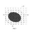
- FIG. 7is a schematic diagram representing a simplified array of voxel values of the slice of the 3D model shown in FIG. 6 following removal of virtual material by application of the limit slice, according to an illustrative embodiment of the invention.
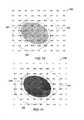
- FIG. 8is a schematic diagram representing a simplified array of distance field values of the limit slice of FIG. 5 , updated to correspond to the newly-modified slice of the 3D model, according to an illustrative embodiment of the invention.
- FIG. 9is a schematic diagram illustrating the determination of an offset value as a function of a given draft angle and a given distance between slices of the 3D model, according to an illustrative embodiment of the invention.
- FIG. 10is a schematic diagram representing a simplified array of distance field values of the limit slice of FIG. 8 , modified according to an offset value, for application as a template against the next slice of the 3D model, according to an illustrative embodiment of the invention.
- FIG. 11is a schematic diagram representing a simplified array of voxel values of the next slice of the 3D model following application of the limit slice of FIG. 10 , according to an illustrative embodiment of the invention.
- FIG. 12is a schematic diagram representing a simplified array of distance field values of a limit slice used in the method of FIG. 3 to add virtual material to a 3D voxel-based model (an “add” operation), according to an illustrative embodiment of the invention.
- FIG. 13is a schematic diagram representing a simplified array of voxel values of a slice of the 3D model to which the limit slice of FIG. 12 will be applied in the add operation, according to an illustrative embodiment of the invention.
- FIG. 14is a schematic diagram representing a simplified array of voxel values of the slice of the 3D model shown in FIG. 13 following addition of virtual material by application of the limit slice as a template, according to an illustrative embodiment of the invention.
- FIG. 15is a schematic diagram representing a simplified array of distance field values of the limit slice of FIG. 12 , updated to correspond to the newly-modified slice of the 3D model, according to an illustrative embodiment of the invention.
- FIG. 16is a schematic diagram representing a simplified array of distance field values of the limit slice of FIG. 15 , modified according to an offset value, for application as a template against the next slice of the 3D model, according to an illustrative embodiment of the invention.
- FIG. 17is a schematic diagram representing a simplified array of voxel values of the next slice of the 3D model following application of the limit slice of FIG. 16 , according to an illustrative embodiment of the invention.
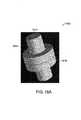
- FIG. 18Ais a screenshot of a 3D model with a mold parting curve and parting direction as shown; the sides of the model are essentially parallel to the parting direction and do not provide adequate draft for extraction from a mold.
- FIG. 18Bis a screenshot of the 3D model of FIG. 18A following a “cut” operation to remove virtual material from the model for compliance with a specified minimum draft angle, according to an illustrative embodiment of the invention.
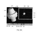
- FIG. 18Cis a screenshot of the 3D model of FIG. 18A following an “add” operation to add virtual material to the model for compliance with a specified minimum draft angle, according to an illustrative embodiment of the invention.
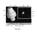
- FIG. 18Dis a screenshot of the 3D model of FIG. 18A following an “add while preserving parting line” operation to add virtual material to the model for compliance with a specified minimum draft angle without obscuring the original mold parting curve, according to an illustrative embodiment of the invention.
- An exemplary method of the inventionproceeds through the voxel volume in a slice-wise manner, modifying each slice of the voxel volume to correct any deviation from an imposed manufacturing constraint.
- the voxel volumeis generally a three-dimensional grid of voxel density values.
- the voxel density valuesmay be one-byte integers ranging from 0 to 255, where a given density value, for example 128, indicates a boundary separating the inside of a virtual object from the outside of the virtual object (i.e. the surface of the object).
- the automatic modification methodproceeds in a step-wise manner, passing through a voxel volume comprising a 3D model one slice at a time, in a single pass.
- an array of distance field valuesis maintained, which represents the cumulative limitations on the “clay” (virtual material) of the current slice implied by the previous slices and the manufacturing constraint.
- the array of distance field valuesis referred to herein as the limit slice.
- the limit sliceis used as a template to modify the current voxel slice.
- the resulting voxel slicemay, in turn, impose additional limitations on the remaining slices by modifying the limit slice.
- the distance field array of the limit sliceis offset by an appropriate amount.
- This offsetis computed as the amount (i.e., radius) by which a properly drafted cone would grow (or shrink) over the distance separating two slices.
- the methodincludes re-triangulating, or otherwise remeshing, the resulting volume to determine the shape of the modified, manufacturable model.
- the modelmay be re-triangulated using a marching cubes algorithm, thereby generating triangles (or other polygonal elements) to represent the surface of a given voxel volume. Any other meshing technique may be used.
- the resulting triangle meshis manifold by construction (i.e. each edge is shared by two triangles).
- Methods of the inventioninclude automatically altering a 3D voxel-based model of arbitrary shape and topology to obey a given manufacturing constraint, such as a minimum draft angle relative to a desired parting curve and parting direction. Methods of the invention leverage the unique properties of voxels to add or remove virtual material to enforce a minimum specified draft angle relative to a given pull direction.
- FIGS. 1A and 1Bdemonstrate an exemplary application of a method for automatically modifying a model to enforce a minimum draft angle.
- FIG. 1Ais a screenshot 100 of a 3D model 110 of an object, as well as a haptic/graphical user interface element (widget) 125 for automatically modifying the model 110 to enforce compliance with a minimum draft angle, relative to the parting curve 115 and parting direction 120 shown.
- the sides of the model 110are parallel to the parting direction 120 and would not provide adequate draft for extraction of the object from a mold.
- FIG. 1Bis a screenshot 150 of the model 130 of FIG. 1A following automatic modification for compliance with a specified minimum draft angle by removal of virtual material from the model, where the draft angle is relative to the indicated parting curve 115 and parting direction 120 .
- the object represented by the model 130 of FIG. 1Bcan now be extracted from its mold insert, because there is sufficient draft.
- FIGS. 2A to 2Ddemonstrate a more complex application of the method for automatically modifying a model to enforce a minimum draft angle.
- FIG. 2Ais a screenshot 200 of a model of a three-dimensional object showing an area of undercut 210 following automatic determination of compliance with a minimum draft angle, relative to the indicated parting curve 205 and parting direction, according to an illustrative embodiment of the invention. Screenshot 200 shows the model of the object before it is modified to enforce compliance with a minimum draft angle.
- FIG. 2Bis a screenshot 225 of the model of FIG. 2A , along with a haptic/graphical user interface element 235 , following automatic modification of the model for compliance with the specified minimum draft angle, thereby eliminating the undercut by adding virtual material 240 , according to an illustrative embodiment of the invention.
- the haptic/graphical user interface (H/GUI) element 235is positioned to indicate parting direction 230 relative to parting curve 205 .
- the usermay manipulate the element 235 , which may, itself, be haptically rendered, to select the parting direction 230 .
- the H/GUI elementmay also be used, for example, to select the parting curve 205 , to rotate the model for viewing, and/or to perform other manipulations.
- Screenshot 225is illustrative of the result of an “add” operation.
- Added material 240has eliminated the undercut 210 identified in FIG. 2A and has brought the model of the object in screenshot 225 into compliance with the minimum draft angle such that the object may be properly removed from its mold insert.
- FIG. 2Cis a screenshot 250 showing an upward-looking view of the model of FIG. 2A , indicating another area of undercut 255 following automatic determination of compliance with a minimum draft angle, relative to the indicated parting curve 205 and parting direction 230 , according to an illustrative embodiment of the invention.
- Screenshot 250shows the model of the object before an add material operation takes place to enforce compliance with a minimum draft angle.
- FIG. 2Dis a screenshot 275 showing the view of FIG. 2C , following automatic modification of the model for compliance with the specified minimum draft. angle, thereby eliminating the undercut, according to an illustrative embodiment of the invention.
- Screenshot 275is illustrative of the result of an “add” operation. In this example, the modifications shown in FIGS. 2B and 2D were performed simultaneously.
- methods for enforcing minimum draft angleemploy the following inputs, as provided by the user and/or as automatically determined:
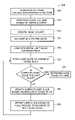
- FIG. 3is a block diagram 300 featuring a method of modifying a voxel-based model of an arbitrarily-shaped 3D object for compliance with a manufacturing constraint, such as draft angle, in which virtual material is added or removed in a slice-by-slice manner, according to an illustrative embodiment of the invention.
- the method of FIG. 3 as described herein belowassumes that the parting direction is vertically upward, and that the draft angle is to be fixed in the upper portion of the model above the parting curve. If this is not the case, the voxel representation can be rotated to satisfy this condition.
- each sliceis a horizontal slice, and the step-wise procedure proceeds vertically upward or downward.
- an axis of the voxel volume representing a 3D modelis aligned with a user-defined or automatically-defined three dimensional parting direction along which the mold halves will be pulled apart.
- the three dimensional parting directionmay be a unit vector in three dimensions.
- the voxel volumeis partitioned along a parting curve.
- the parting curve, (or set of curves)indicates where the mold halves will part, thereby dividing the surface of the model into an “upper” and “lower” half.
- a parting surfaceis generated based on the parting curve, which is then used to classify each voxel as being either above the parting surface or below the parting surface.
- Each voxelmay be marked as being in either the upper or lower half.
- Step 315 of the method of FIG. 3is an optional step involving the creation of a mask volume.
- the mask volumeincludes portions of the model (and/or the space around the model) that are to remain unchanged following application of the automatic modification procedure.
- the mask volumemay be user defined.
- the mask volumerestricts the regions in which modifications may be made, thus allowing increased user control.
- Step 320 of the method of FIG. 3is the determination of the starting (initial) slice. In some embodiments, this step 320 includes determining both the starting and ending slice locations.
- a “cut” operationthe initial slice is chosen at the middle of the model near the parting line, and the modification proceeds upward in a slice-by-slice manner.
- an “add” operationthe initial slice is chosen at a location above the model, and the modification proceeds downward in a slice-by-slice manner.
- Step 325 of the method of FIG. 3is the computation of the initial limit slice distance field.
- a limit sliceis applied like a template to a corresponding voxel slice, and the distance field of a limit slice is an array of values indicating the distance (i.e. in arbitrary grid units) to the edge of the template.
- the limit sliceaccounts for the shape of the model as modified in previous slices, as well as an offset value that is indicated by an imposed minimum draft angle.
- the initial limit sliceis obtained by projecting the parting curve down to the initial slice height (z-value), while offsetting the projected curve conically outward according to the desired draft angle and the distance of projection. This is described in more detail with respect to FIG. 9 .
- an “add” operationthe initial limit slice is empty.
- Steps 330 , 335 , 345 , and 350are repeated as the method proceeds slice by slice through the 3D model.
- Step 330is the application of the current limit slice to the current voxel slice as a template to modify the voxel slice in compliance with the minimum draft angle.
- step 330further includes applying the limit slice to the current voxel slice only where the mask volume allows.
- step 330includes performing a union operation with the voxel slice and the limit slice that in some cases will add virtual material to the current voxel slice.
- step 330includes performing an intersection operation that in some cases will remove virtual material from the current voxel slice.
- step 335determines whether the current voxel slice is the last slice. If it is, then step 340 retriangulates the voxel volume to obtain the modified, draft-obeying shape. If it is not, the method proceeds to step 345 , where the current limit slice is updated based on the resulting voxel slice.
- the distance field values of the limit sliceare further modified in step 350 , according to the offset imposed by the minimum draft angle in advancing to the next slice (i.e., see FIG. 9 ).
- the resulting limit sliceis then applied to the next voxel slice in step 330 , and the process continues until the last voxel slice is reached.
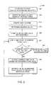
- FIG. 4is a block diagram 400 featuring a method of modifying a voxel-based model of an arbitrarily-shaped 3D object for compliance with a manufacturing constraint, such as draft angle, in which virtual material is added to enforce the constraint and virtual material is removed to preserve the parting curve where mold halves meet.
- the method of FIG. 4includes the steps of aligning an axis of the voxel volume with the parting direction (step 305 ); partitioning the voxel volume along a parting curve (step 310 ); optionally creating a mask volume (step 315 ); determining a starting slice (step 320 ); and computing the initial limit slice distance field (step 325 ).
- the method in FIG. 4includes step 405 of computing a limit cone volume (or, analogously, a second limit slice inferred by the limit cone volume).
- the second limit lo sliceis referred to herein as the Parting Curve (PC) base.
- the PC-baseis represented as a two dimensional distance field, and the distance values in it are obtained by projecting the parting curve downward to a plane below the parting line, and then offsetting it outward according to the desired draft angle and the projection distance.
- the PC-baseis not modified during the slice-wise steps that follow, it is only referenced.
- the PC-basecan be interpreted as a “limit cone volume” implied by the parting curve. Under this interpretation, any material visible outside of this limit cone volume would either violate the draft angle or would require that the parting line be modified outward. Therefore, cutting material outside of this limit volume implies that the parting line will be preserved.
- Steps 330 , 410 , 335 , 345 , and 350 of the method FIG. 4are repeated as the method proceeds slice by slice through the 3D model.
- Step 330is the application of the current limit slice to the current voxel slice as a template to modify the voxel slice in compliance with the minimum draft angle.
- step 330includes performing a union operation with the voxel slice and the limit slice.
- step 410 of the method of FIG. 4intersects the resulting voxel slice with the corresponding slice from the limit cone volume (which can be determined directly from the PC-base slice, using the vertical distance between the desired limit cone volume slice and the PC-base slice).
- Step 410may result in the cutting of virtual material from the model, if that material lies outside the limit cone volume, so that the parting line will be preserved.
- step 335determines whether the current voxel slice is the last slice. If it is, then step 340 retriangulates the voxel volume to obtain the modified, draft-obeying shape. If it is not, the method proceeds to step 345 , where the current limit slice is updated with the resulting voxel slice. The distance field values of the limit slice are further modified in step 350 , according to the offset imposed by the minimum draft angle in advancing to the next slice. The resulting limit slice is then applied to the next voxel slice in step 330 , and the process continues until the last voxel slice is reached.
- the unique parting line curveit is possible to determine the unique parting line curve automatically given only a description of the model and a pull direction. For example, a sphere has a single unique parting line curve (the equator) for any pull direction. Other models may have several distinct valid parting line curves given a description of the model and a pull direction. For these generally more complex situations, the user may be prompted to specify additional information to select one particular parting line curve.
- the methodgenerates a valid parting line curve by identifying each triangle in the model as being either “forward” or “backward”-facing with respect to the pull direction. Then, the method looks through the triangles and collects all edges that have one forward and one backward facing neighboring triangle. The method connects these edges into a curve, thus separating the “front” half of the model from the “back” half. This method is useful for certain models, including the sphere example above.
- a method of the inventionincludes having a user choose a specific parting line curve.
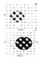
- FIGS. 5–8 and 10 – 17demonstrate various steps in the methods of FIGS. 3 and 4 using representations of simplified limit slices and voxel slices.
- the representationsare 9 ⁇ 9 arrays of values, although it should be understood that realistic slices generally contain much more data.
- distance field values of limit slicesare scaled such that the distance between adjacent grid-points is 1.0.
- the “edge” of the limit volume implied by this limit sliceis determined by finding the contour of points whose distance value is 0.0.
- another scaling conventionmay be used.
- the distance field of a given limit sliceis preferably an evenly-spaced grid of distance values.
- the value at each grid pointrepresents the shortest 2D distance in the slice plane to the intersection of the surface of the limit volume with the current slice. These distances are measured in two-dimensions and represent the distance in “grid” units.
- a sign bitis added to each distance value, to indicate if the point lies inside (positive) or outside (negative) the curve loop.
- a distance-field grid point with a value of 1.0implies that the curve approaches that grid-point to a distance of 1.0, but not closer. If a circle of radius 1.0 were drawn around the grid point, the curve would touch the circle at some point, but would not enter the circle.
- distance fieldscan serve at least two roles.
- One roleis to take a planar curve and to determine a distance field based on that curve.
- Another roleis that once a distance field is obtained, its values can be analyzed and curves may be found in that distance field.
- the role of the distance fieldsincludes (1) finding a locus of points and (2) connecting these points by a curve. The locus of all points with distance value 0 provides the original curve. If all points having distance value d are found, where d>0, then one or more curve loops can be generated which represent the original curve “shrunk inward” by a distance d.
- one or more curve loops which represent the original curve “grown outward,” or “inflated”may be generated by finding all points for a given negative d (i.e., d ⁇ 0).
- the limit slice at a given level kcaptures the shape of the object at that level.
- the inventionthen offsets all distance values by the amount that the draft angle implies, and the result is the offset of the 0-valued iso-line, shrinking inward or growing outward as appropriate.
- the modified limitmay then be applied to the next slice.
- the voxel slices illustrated in the following figureshave iso-values (voxel values) that are also distributed over a uniform 9 ⁇ 9 grid. Each iso-value lies in the range [0,255], where 0 implies empty space, 255 implies solid material inside the model, and the surface is defined to lie at 128.
- the iso-valuesare scaled such that they transition from 0 to 255 over a distance of 4 grid-spaces, changing by at most 64 between adjacent grid-points. This scaling approach is complementary to haptic rendering approaches, as applied to the voxel model.
- the interior of the voxel model sliceshave iso-values greater than 128.
- a voxel sliceis a type of restricted distance field.
- iso-valueschange 64 times as quickly as distance values, and the “surface” of a voxel volume is defined to be the contour of value 128, instead of the contour of distance 0 used by distance fields.
- iso-valuesare limited to the range [0,255], while distance field values can have any magnitude.
- FIGS. 5–11illustrate a “cut” operation according to one embodiment of the method of FIG. 3 .
- FIG. 5is a schematic diagram representing a simplified array of distance field values of a limit slice 500 used in the method of FIG. 3 to remove virtual material from a 3D voxel-based model.
- This limit slice 500is referred to herein as L 0 and defines the curve 505 , determined according to the above-described sequence of operations of FIG. 3 (steps 305 , 310 , 320 , and 325 ).
- L 0is to be applied to a corresponding voxel slice, V 0 , in step 330 of the method of FIG. 3 .
- FIG. 6is a schematic diagram representing V 0 , a simplified array of voxel values 600 of a slice of the 3D model to which the limit slice of FIG. 5 , L 0 ,will be applied as a template in the cut operation.
- Curve 605 in the voxel slicerepresents the location of the surface of the 3D model in this slice.
- Curve 505 from the limit slice L 0(converted to corresponding iso-values) is shown for reference.
- the limit slice valuesare converted to voxel values before taking the minimum, for example, by multiplying by 64.0, then adding 128, and finally clamping to the range [0,255]. Clamping sets the value to 0 if the result is less than 0 and sets the value to 255 if the result is greater than 255. This is generally necessary where the voxel slice contains 8-bit integer values, which can only represent values in the range [0,255]. In some embodiments the method may be adapted for use with other bit-length values, for example.
- FIG. 7shows the resulting array of voxel values 700 following the intersection of V 0 and L 0 .
- the resulting voxel sliceis V 1 , as computed according to Equation 1 above.
- the darkened region 705represents virtual material remaining in the current voxel slice following application of the limit slice.
- FIG. 8is a schematic diagram representing the limit slice L 1 (reference 800 ) following modification according to the updated voxel slice, V 1 .
- FIG. 9is a schematic diagram 900 illustrating the determination of an offset value 920 as a function of a given draft angle “alpha” 910 and a given distance “h” 915 between slices of the voxel volume.
- This offset 920represents the distance by which the radius of a cone 905 (with cone-angle alpha 910 ) shrinks as a slice through that cone proceeds upward by a distance h 915 .
- FIG. 10is a schematic diagram representing the array of distance field values L 2 (reference 1000 ) following modification according to an offset value.
- the “cut” operationproceeds according to the method of FIG. 3 by advancing to the next slice of the voxel volume and applying limit slice L 2 .
- FIG. 11shows the resulting voxel slice 1100 following application of limit slice L 2 .
- the new voxel slice, before application of limit slice L 2was similar to previous voxel slice V 0 , but, of course, the method would work where the new voxel slice, prior to application of the corresponding limit slice, differs from V 0 more prominently.
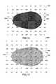
- FIGS. 12–17illustrate an “add” operation according to the method of FIG. 3 .
- materialis added as the slices move down from the outside of the model toward the parting line curve.
- the depicted slicesare simplified for illustrative purposes. Realistic slices may contain significantly more data.
- the limit slicerepresents a lower bound, i.e., a minimum volume that the voxel slice contains, although the voxel slice may also contain other areas that the limit does not yet require.
- the solid area of the model represented by the voxel and limit slicesgrows.
- FIG. 12is a schematic diagram representing an exemplary array 1200 of distance field values of a limit slice L 0 used in an “add” operation, according to an embodiment of the method of FIG. 3 .
- the limit slice L 0defines the curve 1205 , and is determined according to the above-described sequence of operations of FIG. 3 (steps 305 , 310 , 320 , and 325 ).
- L 0is to be applied to a corresponding voxel slice, V 0 , in step 330 of the method of FIG. 3 .
- FIG. 13is a schematic diagram representing V 0 , an array of voxel values 1300 of a slice of the 3D model to which the limit slice 1200 of FIG. 12 , L 0 , will be applied in the “add” operation.
- Curve 1305 in the voxel slicerepresents the location of the surface of the 3D model in this slice.
- Curve 1205 from the limit slice(converted to corresponding iso-values) is shown for reference.
- V 1max( V 0 ,L 0 ) (5) where V 1 is the resulting voxel slice.
- the limit slice valuesare converted to voxel values before taking the maximum.
- FIG. 14shows the resulting array of voxel values 1400 following the unioning of V 0 with L 0 .
- the resulting voxel sliceis V 1 , as computed according to Equation 5 above.
- the darkened region 1405represents virtual material in the current voxel slice following application of the limit slice (via unioning).
- FIG. 15is a schematic diagram representing the limit slice L 1 1500 following modification according to the updated voxel slice, V 1 .
- Conversion of voxel values into distance-field valuesmay involve “undoing” the clamping of values to the range [0,255]. For example, the voxel value 0 is converted to a distance value of ⁇ , and the voxel value 255 is converted to a distance value of ⁇ .
- step 350involves offsetting the limit slice L 1 by a distance that is related to both the desired angle “alpha” as well as the distance “h” between slices, as illustrated in the schematic diagram of FIG. 9 .
- the offsetis added to the limit values, not subtracted as in the “cut” operation.
- this offsetrepresents the distance by which the radius of a cone (with con-angle alpha) grows as a slice through that cone proceeds by a distance h.
- FIG. 16is a schematic diagram representing the array of distance field values L 2 1605 following modification according to an offset value.
- the “add” operationproceeds according to the method of FIG. 3 by advancing to the next slice of the voxel volume and applying limit slice L 2 .
- FIG. 17shows the resulting voxel slice 1700 following application of limit slice L 2 .
- the new voxel slice, before application of limit slice L 2was similar to previous voxel slice V 0 , but, of course, the method would work where the new voxel slice, prior to application of the corresponding limit slice, differs from V 0 more prominently.
- FIGS. 18A to 18Ddemonstrate application of the methods of FIGS. 3 and 4 to an exemplary 3D model. These particular examples employ a rather large draft angle of 15 degrees to illustrate the results more clearly. Any draft angle may be chosen. For example, in certain applications, a draft angle of 10 degrees or less, 5 degrees or less, 3 degrees or less, 2 degrees or less, or 1 degree or less may be used. Of course, values greater than 10 degrees may be used as well.
- FIG. 18Ais a screenshot 1800 of a 3D model with a mold parting curve 1810 and parting direction 1815 as shown. The sides of the model are essentially parallel to the parting direction 1815 and do not provide adequate draft for extraction from a mold.
- FIG. 18Bis a screenshot 1825 of the 3D model of FIG. 18A following a “cut” operation, according to the method of FIG. 3 , to remove virtual material from the model 1830 for compliance with the specified minimum draft angle of 15 degrees.
- a supplementary view 1843 of the objectis provided in the screenshot 1825 , and control buttons are provided 1835 , 1836 , 1837 , 1838 , 1839 , 1840 , and 1841 .
- FIG. 18Cis a screenshot 1850 of the 3D model of FIG. 18A following an “add” operation, according to the method of FIG. 3 , to add virtual material to the model 1855 for compliance with a specified minimum draft angle. Note that the result of the “add” operation has obscured the original parting curve 1810 .
- a supplementary view 1860 of the objectis provided in the screenshot 1850 , and control buttons are provided 1835 , 1836 , 1837 , 1838 , 1839 , 1840 , and 1841 .
- FIG. 18Dis a screenshot 1875 of the 3D model of FIG. 18A following an “add while preserving parting line” operation, according to the method of FIG. 4 , to add virtual material to the model for compliance with a specified minimum draft angle without modifying or obscuring the original mold parting curve.
- a supplementary view 1885 of the objectis provided in the screenshot 1875 , and control buttons are provided 1835 , 1836 , 1837 , 1838 , 1839 , 1840 , and 1841 .
- the inventionincludes an apparatus for performing the methods described herein.
- the apparatusincludes a memory for storing a code that defines a set of instructions, and a processor for executing the set of instructions for performing the methods of the invention.
- the apparatusmay include a haptic and/or graphical user interface device (HWGUI device) in communication with the processor.
- HWGUI devicehaptic and/or graphical user interface device
- the H/GUI devicemay be the Phantom® haptic interface device manufactured by SensAble Technologies, Inc., in Woburn, Mass., described in U.S. Pat. No. 6,417,638, issued to Rodomista et al.
- the HI/GUI device 2712allows a user to manipulate a cursor/tool and/or provides haptic feedback to the user. Force associated with the haptic feedback may be determined.
- an embodiment of the inventionincludes a haptic/graphical user interface element (widget) to facilitate user interaction in the methods described herein.
- a computer hardware apparatusmay be used in carrying out any of the methods described herein.
- the apparatusmay include, for example, a general purpose computer, an embedded computer, a laptop or desktop computer, or any other type of computer that is capable of running software, issuing suitable control commands, receiving graphical user input, and recording information.
- the computertypically includes one or more central processing units for executing the instructions contained in software code that embraces one or more of the methods described herein.
- the softwaremay include one or more modules recorded on machine-readable media, where the term machine-readable media encompasses software, hardwired logic, firmware, object code, and the like. Additionally, communication buses and I/O ports may be provided to link any or all of the hardware components together and permit communication with other computers and computer networks, including the internet, as desired.
Landscapes
- Engineering & Computer Science (AREA)
- Architecture (AREA)
- Computer Graphics (AREA)
- Computer Hardware Design (AREA)
- General Engineering & Computer Science (AREA)
- Software Systems (AREA)
- Physics & Mathematics (AREA)
- General Physics & Mathematics (AREA)
- Theoretical Computer Science (AREA)
- Chemical & Material Sciences (AREA)
- Manufacturing & Machinery (AREA)
- Materials Engineering (AREA)
Abstract
Description
- a voxel volume description of the shape or model to be modified; an arbitrary 3D parting direction (a unit vector in 3 dimensions), along which the mold halves will be pulled apart;
- a parametric description of the parting curve (or set of curves) at which the mold halves will part, partitioning the voxel model into an “upper” and a “lower” half;
- a desired draft angle;
- a choice of which half (upper or lower) of the model to modify;
- a choice of how the draft angle is to be enforced, for example, by performing a “cut” procedure to remove overhanging material, by performing an “add” procedure to fill undercuts, or by performing an “add” procedure to fill undercuts while removing material if necessary to preserve the parting curve; and, optionally,
- a user-defined mask volume to restrict areas in which modifications may be made, allowing the user finer control, if desired.
V1=min(V0,L0) (1)
where V1is the resulting voxel slice. The limit slice values are converted to voxel values before taking the minimum, for example, by multiplying by 64.0, then adding 128, and finally clamping to the range [0,255]. Clamping sets the value to 0 if the result is less than 0 and sets the value to 255 if the result is greater than 255. This is generally necessary where the voxel slice contains 8-bit integer values, which can only represent values in the range [0,255]. In some embodiments the method may be adapted for use with other bit-length values, for example.
L1=min(L0,V1) (2)
Offset=h*tan(alpha) (3)
For example, where alpha=20 degrees and h=1, the corresponding offset=0.364. The offset is applied to L1, and a new limit slice L2is obtained, according to Equation 4 as follows:
L2=L1−offset (4)
V1=max(V0,L0) (5)
where V1is the resulting voxel slice. The limit slice values are converted to voxel values before taking the maximum.
L1=max(L0,V1) (6)
Conversion of voxel values into distance-field values may involve “undoing” the clamping of values to the range [0,255]. For example, the
L2=L1+offset (7)
Claims (48)
Priority Applications (1)
| Application Number | Priority Date | Filing Date | Title |
|---|---|---|---|
| US10/856,699US7149596B2 (en) | 2004-01-13 | 2004-05-28 | Apparatus and methods for modifying a model of an object to enforce compliance with a manufacturing constraint |
Applications Claiming Priority (2)
| Application Number | Priority Date | Filing Date | Title |
|---|---|---|---|
| US53606804P | 2004-01-13 | 2004-01-13 | |
| US10/856,699US7149596B2 (en) | 2004-01-13 | 2004-05-28 | Apparatus and methods for modifying a model of an object to enforce compliance with a manufacturing constraint |
Publications (2)
| Publication Number | Publication Date |
|---|---|
| US20050154481A1 US20050154481A1 (en) | 2005-07-14 |
| US7149596B2true US7149596B2 (en) | 2006-12-12 |
Family
ID=34743104
Family Applications (1)
| Application Number | Title | Priority Date | Filing Date |
|---|---|---|---|
| US10/856,699Expired - LifetimeUS7149596B2 (en) | 2004-01-13 | 2004-05-28 | Apparatus and methods for modifying a model of an object to enforce compliance with a manufacturing constraint |
Country Status (1)
| Country | Link |
|---|---|
| US (1) | US7149596B2 (en) |
Cited By (33)
| Publication number | Priority date | Publication date | Assignee | Title |
|---|---|---|---|---|
| US20060068931A1 (en)* | 2004-03-10 | 2006-03-30 | Steven Aoyama | Mold for a golf ball |
| US20080088621A1 (en)* | 2006-10-11 | 2008-04-17 | Jean-Jacques Grimaud | Follower method for three dimensional images |
| US20080246761A1 (en)* | 2006-11-30 | 2008-10-09 | Daniel Faken | Systems for hybrid geometric/volumetric representation of 3d objects |
| US20090226080A1 (en)* | 2008-03-10 | 2009-09-10 | Apple Inc. | Dynamic Viewing of a Three Dimensional Space |
| WO2011106672A1 (en) | 2010-02-26 | 2011-09-01 | Sensable Technologies, Inc. | Systems and methods for creating near real-time embossed meshes |
| US8019579B1 (en)* | 2007-10-16 | 2011-09-13 | The Mathworks, Inc. | Graphical user interface for viewing or editing an executable block diagram model |
| US20120239169A1 (en)* | 2011-03-18 | 2012-09-20 | Rockwell Automation Technologies, Inc. | Transparent models for large scale optimization and control |
| US20120239164A1 (en)* | 2011-03-18 | 2012-09-20 | Rockwell Automation Technologies, Inc. | Graphical language for optimization and use |
| US8509933B2 (en) | 2010-08-13 | 2013-08-13 | 3D Systems, Inc. | Fabrication of non-homogeneous articles via additive manufacturing using three-dimensional voxel-based models |
| US8849015B2 (en) | 2010-10-12 | 2014-09-30 | 3D Systems, Inc. | System and apparatus for haptically enabled three-dimensional scanning |
| US9030411B2 (en) | 2004-06-29 | 2015-05-12 | 3D Systems, Inc. | Apparatus and methods for haptic rendering using a haptic camera view |
| US9305391B2 (en) | 2013-03-15 | 2016-04-05 | 3D Systems, Inc. | Apparatus and methods for detailing subdivision surfaces |
| WO2016196382A1 (en)* | 2015-06-01 | 2016-12-08 | Velo3D, Inc. | Three-dimensional printing and three-dimensional objects formed using the same |
| US9632732B2 (en) | 2012-06-15 | 2017-04-25 | Hewlett-Packard Development Company, L.P. | Print product representation |
| US9662840B1 (en) | 2015-11-06 | 2017-05-30 | Velo3D, Inc. | Adept three-dimensional printing |
| US9821411B2 (en) | 2014-06-20 | 2017-11-21 | Velo3D, Inc. | Apparatuses, systems and methods for three-dimensional printing |
| US20170360535A1 (en)* | 2014-12-22 | 2017-12-21 | Dental Wings Inc. | Pre-forms and methods for using same in the manufacture of dental prostheses |
| US9919360B2 (en) | 2016-02-18 | 2018-03-20 | Velo3D, Inc. | Accurate three-dimensional printing |
| US9962767B2 (en) | 2015-12-10 | 2018-05-08 | Velo3D, Inc. | Apparatuses for three-dimensional printing |
| US20180126649A1 (en) | 2016-11-07 | 2018-05-10 | Velo3D, Inc. | Gas flow in three-dimensional printing |
| US10144176B1 (en) | 2018-01-15 | 2018-12-04 | Velo3D, Inc. | Three-dimensional printing systems and methods of their use |
| US10252336B2 (en) | 2016-06-29 | 2019-04-09 | Velo3D, Inc. | Three-dimensional printing and three-dimensional printers |
| US10272525B1 (en) | 2017-12-27 | 2019-04-30 | Velo3D, Inc. | Three-dimensional printing systems and methods of their use |
| US10315252B2 (en) | 2017-03-02 | 2019-06-11 | Velo3D, Inc. | Three-dimensional printing of three-dimensional objects |
| CN110300936A (en)* | 2017-02-16 | 2019-10-01 | 克林格伦贝格股份公司 | For designing and processing the method and corresponding machining tool and software of gear |
| US10449696B2 (en) | 2017-03-28 | 2019-10-22 | Velo3D, Inc. | Material manipulation in three-dimensional printing |
| US10611092B2 (en) | 2017-01-05 | 2020-04-07 | Velo3D, Inc. | Optics in three-dimensional printing |
| WO2020076304A1 (en)* | 2018-10-09 | 2020-04-16 | Hewlett-Packard Development Company, L.P. | Modifying object geometries based on radiant heating distribution |
| US11103787B1 (en) | 2010-06-24 | 2021-08-31 | Gregory S. Rabin | System and method for generating a synthetic video stream |
| US11691343B2 (en) | 2016-06-29 | 2023-07-04 | Velo3D, Inc. | Three-dimensional printing and three-dimensional printers |
| US11999110B2 (en) | 2019-07-26 | 2024-06-04 | Velo3D, Inc. | Quality assurance in formation of three-dimensional objects |
| US12070907B2 (en) | 2016-09-30 | 2024-08-27 | Velo3D | Three-dimensional objects and their formation |
| US12243165B2 (en) | 2019-11-14 | 2025-03-04 | James R. Glidewell Dental Ceramics, Inc. | Method and system of providing retention for computer-aided design of removable objects |
Families Citing this family (29)
| Publication number | Priority date | Publication date | Assignee | Title |
|---|---|---|---|---|
| US7281229B1 (en)* | 2004-09-14 | 2007-10-09 | Altera Corporation | Method to create an alternate integrated circuit layout view from a two dimensional database |
| EP1710720B1 (en)* | 2005-04-08 | 2009-07-08 | Dassault Systèmes | Method of computer-aided design of a modeled object having several faces |
| US7933756B2 (en)* | 2007-03-07 | 2011-04-26 | Riwebb Incorporated | Multi-representational model having two or more models of a mechanical object |
| CN102164734B (en)* | 2008-07-25 | 2014-06-11 | 康奈尔大学 | Apparatus and methods for digital manufacturing |
| FR2956832B1 (en)* | 2010-02-26 | 2012-03-23 | Eric Ganci | SYSTEM AND METHOD FOR MANUFACTURING VEHICLE PROTECTION MASKS |
| US8579620B2 (en)* | 2011-03-02 | 2013-11-12 | Andy Wu | Single-action three-dimensional model printing methods |
| JP2013214275A (en)* | 2012-03-08 | 2013-10-17 | Canon Inc | Three-dimensional position specification method |
| US10176291B2 (en)* | 2012-07-06 | 2019-01-08 | Siemens Product Lifecycle Management Software Inc. | Ordering optional constraints in a variational system |
| US9792734B2 (en)* | 2013-09-13 | 2017-10-17 | Carnegie Mellon University | Methods and software for volume-centric shape abstraction and simplification of a 3D digital model |
| US9844917B2 (en)* | 2014-06-13 | 2017-12-19 | Siemens Product Lifestyle Management Inc. | Support structures for additive manufacturing of solid models |
| ES2899960T3 (en) | 2014-08-29 | 2022-03-15 | Microsoft Technology Licensing Llc | Manufacture of three-dimensional objects |
| KR20160073188A (en)* | 2014-12-16 | 2016-06-24 | 한국전자통신연구원 | System and method for pre-verification stability of 3d printing output |
| GB201512304D0 (en)* | 2015-07-13 | 2015-08-19 | Whispering Gibbon Ltd | Preparing a polygon mesh for printing |
| ES2953536T3 (en) | 2016-02-25 | 2023-11-14 | Stratasys Ltd | GPU Material Mapping for 3D Printing Using 3D Distance Fields |
| US10946588B2 (en) | 2016-03-04 | 2021-03-16 | President And Fellows Of Harvard University | Systems and methods for automated nozzle design and 3D printing |
| US11087535B2 (en) | 2016-10-14 | 2021-08-10 | Hewlett-Packard Development Company, L.P. | Rebuilding three-dimensional models to provide simplified three-dimensional models |
| KR101905993B1 (en)* | 2016-10-31 | 2018-10-10 | 현대자동차주식회사 | Interior parts for vehicle and method for manufacturing the same |
| US11734471B2 (en) | 2017-06-05 | 2023-08-22 | Autodesk, Inc. | Topology optimization for subtractive manufacturing techniques |
| US11521351B2 (en)* | 2017-07-10 | 2022-12-06 | Hewlett-Packard Development Company, L.P. | Associating object property data with locations |
| WO2019210056A1 (en)* | 2018-04-26 | 2019-10-31 | Markforged, Inc. | System and method for minimizing deviations in 3d printed and sintered parts |
| US11084224B2 (en)* | 2019-02-19 | 2021-08-10 | Arevo, Inc. | Three dimensional infill in additive manufacturing |
| US11983832B2 (en)* | 2019-04-25 | 2024-05-14 | Hewlett-Packard Development Company, L.P. | Compensating for dimensional variation in 3D printing |
| GB201915527D0 (en)* | 2019-10-25 | 2019-12-11 | Infold Ab | Method for identifying a parting line |
| CN112861202A (en)* | 2021-02-19 | 2021-05-28 | 珠海格力精密模具有限公司 | Automatic die drawing method and system for part model |
| CN113183470B (en)* | 2021-05-12 | 2022-07-15 | 电子科技大学 | An adaptive layering method for 3D printing that preserves unconventional features of models |
| US12353800B2 (en)* | 2021-06-17 | 2025-07-08 | Dassault Systemes Solidworks Corporation | Parting line identification |
| US12240182B2 (en) | 2021-08-23 | 2025-03-04 | Xerox Corporation | Automated design generation for additive manufacturing with an accessible support volume |
| US11656602B2 (en)* | 2021-08-23 | 2023-05-23 | Palo Alto Research Center Incorporated | Physics-aware automatic spatial planning for subtractive and hybrid manufacturing |
| US20230297734A1 (en)* | 2022-03-16 | 2023-09-21 | Autodesk, Inc. | Voxel-based approach for design models |
Citations (178)
| Publication number | Priority date | Publication date | Assignee | Title |
|---|---|---|---|---|
| US2475484A (en) | 1946-05-14 | 1949-07-05 | Nise Dwight Dee De | Method and means for imparting feel back to a manually-movable control element |
| US3168203A (en) | 1960-07-07 | 1965-02-02 | Gen Mills Inc | Manually operated hydraulic actuator control having feel-back |
| US3263824A (en) | 1963-12-20 | 1966-08-02 | Northrop Corp | Servo controlled manipulator device |
| US3449008A (en) | 1967-06-08 | 1969-06-10 | Gen Dynamics Corp | Object handling system with remote manual control |
| US3531868A (en) | 1968-04-18 | 1970-10-06 | Ford Motor Co | Surface scanner for measuring the coordinates of points on a three-dimensional surface |
| US3618786A (en) | 1969-01-02 | 1971-11-09 | Gen Electric | Material-handling apparatus with end effector force resolver and feedback |
| US3637092A (en) | 1970-04-30 | 1972-01-25 | Gen Electric | Material-handling apparatus |
| US3920972A (en) | 1974-07-16 | 1975-11-18 | Cincinnati Milacron Inc | Method and apparatus for programming a computer operated robot arm |
| US3944798A (en) | 1974-04-18 | 1976-03-16 | Eaton-Leonard Corporation | Method and apparatus for measuring direction |
| US4062455A (en) | 1976-11-22 | 1977-12-13 | Flatau Carl R | Remote manipulator |
| US4150803A (en) | 1977-10-05 | 1979-04-24 | Fernandez Carlos P | Two axes controller |
| US4216467A (en) | 1977-12-22 | 1980-08-05 | Westinghouse Electric Corp. | Hand controller |
| US4302138A (en) | 1978-02-01 | 1981-11-24 | Alain Zarudiansky | Remote handling devices |
| US4367532A (en) | 1979-10-12 | 1983-01-04 | Nordson Corporation | Manually programmable robot with power-assisted motion during programming |
| US4420808A (en) | 1980-04-01 | 1983-12-13 | United Technologies Corporation | Multi-axis force stick, self-trimmed aircraft flight control system |
| US4521685A (en) | 1982-03-01 | 1985-06-04 | Lord Corporation | Tactile sensor for an industrial robot or the like |
| US4604016A (en) | 1983-08-03 | 1986-08-05 | Joyce Stephen A | Multi-dimensional force-torque hand controller having force feedback |
| US4632341A (en) | 1985-02-06 | 1986-12-30 | The United States Of America As Represented By The Secretary Of The Air Force | Stabilizing force feedback in bio-actuated control systems |
| US4638798A (en) | 1980-09-10 | 1987-01-27 | Shelden C Hunter | Stereotactic method and apparatus for locating and treating or removing lesions |
| US4653011A (en) | 1984-10-29 | 1987-03-24 | Mitutoyo Mfg. Co., Ltd. | Method of measuring by coordinate measuring instrument and coordinate measuring instrument |
| US4654648A (en) | 1984-12-17 | 1987-03-31 | Herrington Richard A | Wireless cursor control system |
| US4655673A (en) | 1983-05-10 | 1987-04-07 | Graham S. Hawkes | Apparatus providing tactile feedback to operators of remotely controlled manipulators |
| US4661032A (en) | 1984-12-20 | 1987-04-28 | Agency Of Industrial Science & Technology, Ministry Of International Trade & Industry | Bilateral master-slave manipulator control device |
| US4670851A (en) | 1984-01-09 | 1987-06-02 | Mitsubishi Denki Kabushiki Kaisha | Vector quantizer |
| US4676002A (en) | 1984-06-25 | 1987-06-30 | Slocum Alexander H | Mechanisms to determine position and orientation in space |
| US4680519A (en) | 1985-09-23 | 1987-07-14 | General Electric Co. | Recursive methods for world-to-joint transformation for a robot manipulator |
| US4686522A (en) | 1985-02-19 | 1987-08-11 | International Business Machines Corporation | Method of editing graphic objects in an interactive draw graphic system using implicit editing actions |
| US4703443A (en) | 1984-02-16 | 1987-10-27 | Kabushiki Kaisha Toshiba | Device for measuring the shape of a three-dimensional object |
| US4729098A (en) | 1985-06-05 | 1988-03-01 | General Electric Company | System and method employing nonlinear interpolation for the display of surface structures contained within the interior region of a solid body |
| US4769763A (en) | 1985-06-28 | 1988-09-06 | Carl-Zeiss-Stiftung | Control for coordinate measuring instruments |
| US4791934A (en) | 1986-08-07 | 1988-12-20 | Picker International, Inc. | Computer tomography assisted stereotactic surgery system and method |
| US4795296A (en) | 1986-11-17 | 1989-01-03 | California Institute Of Technology | Hand-held robot end effector controller having movement and force control |
| US4800721A (en) | 1987-02-13 | 1989-01-31 | Caterpillar Inc. | Force feedback lever |
| US4819195A (en) | 1987-01-20 | 1989-04-04 | The Warner & Swasey Company | Method for calibrating a coordinate measuring machine and the like and system therefor |
| US4823634A (en) | 1987-11-03 | 1989-04-25 | Culver Craig F | Multifunction tactile manipulatable control |
| US4837734A (en) | 1986-02-26 | 1989-06-06 | Hitachi, Ltd. | Method and apparatus for master-slave manipulation supplemented by automatic control based on level of operator skill |
| US4839838A (en) | 1987-03-30 | 1989-06-13 | Labiche Mitchell | Spatial input apparatus |
| US4853874A (en) | 1986-12-12 | 1989-08-01 | Hitachi, Ltd. | Master-slave manipulators with scaling |
| US4888538A (en) | 1986-05-19 | 1989-12-19 | Belorussky Gosudarstvenny Universitet Imeni V.I. Lenina | System for remote transmission of angular position and force between master and slave shafts |
| US4893981A (en) | 1987-03-26 | 1990-01-16 | Kabushiki Kaisha Komatsu Seisakusho | Master/slave type manipulator |
| US4907973A (en) | 1988-11-14 | 1990-03-13 | Hon David C | Expert system simulator for modeling realistic internal environments and performance |
| US4907970A (en) | 1988-03-30 | 1990-03-13 | Grumman Aerospace Corporation | Sidestick-type thrust control simulator |
| US4942538A (en) | 1988-01-05 | 1990-07-17 | Spar Aerospace Limited | Telerobotic tracker |
| US4945501A (en) | 1987-01-20 | 1990-07-31 | The Warner & Swasey Company | Method for determining position within the measuring volume of a coordinate measuring machine and the like and system therefor |
| US4945305A (en) | 1986-10-09 | 1990-07-31 | Ascension Technology Corporation | Device for quantitatively measuring the relative position and orientation of two bodies in the presence of metals utilizing direct current magnetic fields |
| US4961138A (en) | 1987-05-01 | 1990-10-02 | General Datacomm, Inc. | System and apparatus for providing three dimensions of input into a host processor |
| US4973215A (en) | 1986-02-18 | 1990-11-27 | Robotics Research Corporation | Industrial robot with servo |
| US4973111A (en)* | 1988-09-14 | 1990-11-27 | Case Western Reserve University | Parametric image reconstruction using a high-resolution, high signal-to-noise technique |
| US4982504A (en) | 1988-02-18 | 1991-01-08 | C.E. Johansson Ab | Method for determining positional errors and for compensating for such errors, and apparatus for carrying out the method |
| US4988981A (en) | 1987-03-17 | 1991-01-29 | Vpl Research, Inc. | Computer data entry and manipulation apparatus and method |
| US5004391A (en) | 1989-08-21 | 1991-04-02 | Rutgers University | Portable dextrous force feedback master for robot telemanipulation |
| US5007300A (en) | 1989-03-03 | 1991-04-16 | United Kingdom Atomic Energy Authority | Multi-axis hand controller |
| US5019761A (en) | 1989-02-21 | 1991-05-28 | Kraft Brett W | Force feedback control for backhoe |
| US5018922A (en) | 1987-03-26 | 1991-05-28 | Kabushiki Kaisha Komatsu Seisakusho | Master/slave type manipulator |
| US5038089A (en) | 1988-03-23 | 1991-08-06 | The United States Of America As Represented By The Administrator Of The National Aeronautics And Space Administration | Synchronized computational architecture for generalized bilateral control of robot arms |
| US5040306A (en) | 1988-02-18 | 1991-08-20 | Renishaw Plc | Surface-sensing device |
| US5044956A (en) | 1989-01-12 | 1991-09-03 | Atari Games Corporation | Control device such as a steering wheel for video vehicle simulator with realistic feedback forces |
| US5053975A (en) | 1988-06-10 | 1991-10-01 | Hitachi, Ltd. | Master-slave manipulator control |
| US5072361A (en) | 1990-02-01 | 1991-12-10 | Sarcos Group | Force-reflective teleoperation control system |
| US5088055A (en) | 1989-02-22 | 1992-02-11 | Kabushiki Kaisha Okuma Tekkosho | Coordinate measuring apparatus having a stylus friction compensating means |
| US5088046A (en) | 1987-12-19 | 1992-02-11 | Renishaw Plc | Mounting for surface-sensing stylus and a method of using said mounting |
| US5103404A (en) | 1985-12-06 | 1992-04-07 | Tensor Development, Inc. | Feedback for a manipulator |
| US5105367A (en) | 1988-10-19 | 1992-04-14 | Hitachi, Ltd. | Master slave manipulator system |
| US5116051A (en) | 1989-01-12 | 1992-05-26 | Atari Games Corporation | Strain gauge pressure-sensitive video game control |
| US5116180A (en) | 1988-07-18 | 1992-05-26 | Spar Aerospace Limited | Human-in-the-loop machine control loop |
| US5130632A (en) | 1989-12-06 | 1992-07-14 | Hitachi, Ltd. | Manipulator and control method therefor |
| US5131844A (en) | 1991-04-08 | 1992-07-21 | Foster-Miller, Inc. | Contact digitizer, particularly for dental applications |
| US5142931A (en) | 1991-02-14 | 1992-09-01 | Honeywell Inc. | 3 degree of freedom hand controller |
| US5143505A (en) | 1991-02-26 | 1992-09-01 | Rutgers University | Actuator system for providing force feedback to a dextrous master glove |
| US5184319A (en) | 1990-02-02 | 1993-02-02 | Kramer James F | Force feedback and textures simulating interface device |
| US5185561A (en) | 1991-07-23 | 1993-02-09 | Digital Equipment Corporation | Torque motor as a tactile feedback device in a computer system |
| US5189806A (en) | 1988-12-19 | 1993-03-02 | Renishaw Plc | Method of and apparatus for scanning the surface of a workpiece |
| US5193963A (en) | 1990-10-31 | 1993-03-16 | The United States Of America As Represented By The Administrator Of The National Aeronautics And Space Administration | Force reflecting hand controller |
| US5204824A (en) | 1989-08-29 | 1993-04-20 | Mitutoyo Corporation | Method of and apparatus for copy controlling coordinate measuring probe with rotary table |
| US5220260A (en) | 1991-10-24 | 1993-06-15 | Lex Computer And Management Corporation | Actuator having electronically controllable tactile responsiveness |
| US5223776A (en) | 1990-12-31 | 1993-06-29 | Honeywell Inc. | Six-degree virtual pivot controller |
| US5237647A (en) | 1989-09-15 | 1993-08-17 | Massachusetts Institute Of Technology | Computer aided drawing in three dimensions |
| US5239246A (en) | 1992-07-08 | 1993-08-24 | The United States Of America As Represented By The Administrator Of The National Aeronautics And Space Administration | Force reflection with compliance control |
| US5255211A (en) | 1990-02-22 | 1993-10-19 | Redmond Productions, Inc. | Methods and apparatus for generating and processing synthetic and absolute real time environments |
| US5264768A (en) | 1992-10-06 | 1993-11-23 | Honeywell, Inc. | Active hand controller feedback loop |
| US5266875A (en) | 1991-05-23 | 1993-11-30 | Massachusetts Institute Of Technology | Telerobotic system |
| US5333257A (en) | 1991-08-09 | 1994-07-26 | C/A Architects, Inc. | System for displaying selected assembly-facility seating views |
| US5354162A (en) | 1991-02-26 | 1994-10-11 | Rutgers University | Actuator system for providing force feedback to portable master support |
| US5382885A (en) | 1993-08-09 | 1995-01-17 | The University Of British Columbia | Motion scaling tele-operating system with force feedback suitable for microsurgery |
| WO1995002801A1 (en) | 1993-07-16 | 1995-01-26 | Immersion Human Interface | Three-dimensional mechanical mouse |
| US5389865A (en) | 1992-12-02 | 1995-02-14 | Cybernet Systems Corporation | Method and system for providing a tactile virtual reality and manipulator defining an interface device therefor |
| US5396265A (en) | 1990-09-17 | 1995-03-07 | Massachusetts Institute Of Technology | Three-dimensional tactile computer input device |
| US5429140A (en) | 1993-06-04 | 1995-07-04 | Greenleaf Medical Systems, Inc. | Integrated virtual reality rehabilitation system |
| US5438529A (en) | 1994-01-26 | 1995-08-01 | Immersion Human Interface Corporation | Percussion input device for personal computer systems |
| US5446834A (en) | 1992-04-28 | 1995-08-29 | Sun Microsystems, Inc. | Method and apparatus for high resolution virtual reality systems using head tracked display |
| US5482051A (en) | 1994-03-10 | 1996-01-09 | The University Of Akron | Electromyographic virtual reality system |
| US5489830A (en) | 1994-09-09 | 1996-02-06 | Mcdonnell Douglas Corporation | Control system with loadfeel and backdrive |
| US5497452A (en) | 1991-03-14 | 1996-03-05 | International Business Machines Corporation | Method and apparatus for generating a geometric model |
| US5506785A (en)* | 1993-02-11 | 1996-04-09 | Dover Systems Corporation | Method and apparatus for generating hollow and non-hollow solid representations of volumetric data |
| US5515078A (en) | 1992-06-12 | 1996-05-07 | The Computer Museum, Inc. | Virtual-reality positional input and display system |
| WO1996016397A1 (en) | 1994-11-23 | 1996-05-30 | Immersion Human Interface Corporation | Method and apparatus for providing mechanical i/o for computer systems interfaced with elongated flexible objects |
| WO1996022591A1 (en) | 1995-01-18 | 1996-07-25 | Immersion Human Interface Corporation | Method and apparatus for providing high bandwidth, low noise mechanical i/o for computer systems |
| US5555894A (en) | 1993-05-11 | 1996-09-17 | Matsushita Electric Industrial Co., Ltd. | Force sensation exhibiting device, data input device and data input equipment |
| US5587937A (en) | 1993-10-01 | 1996-12-24 | Massachusetts Institute Of Technology | Force reflecting haptic interface |
| WO1996042078A1 (en) | 1995-06-09 | 1996-12-27 | Immersion Human Interface Corporation | Method and apparatus for providing passive fluid force feedback |
| US5589854A (en) | 1995-06-22 | 1996-12-31 | Tsai; Ming-Chang | Touching feedback device |
| USD377932S (en) | 1995-10-31 | 1997-02-11 | Immersion Human Interface Corporation | Mechanical digitizing arm used to input three dimensional data into a computer |
| WO1997006410A1 (en) | 1995-08-07 | 1997-02-20 | Immersion Human Interface Corporation | Method and apparatus for tracking position and orientation of a stylus and for digitizing a 3-d object |
| WO1997012337A1 (en) | 1995-09-27 | 1997-04-03 | Immersion Human Interface Corporation | Safe and low cost computer peripherals with force feedback for consumer applications |
| US5623582A (en) | 1994-07-14 | 1997-04-22 | Immersion Human Interface Corporation | Computer interface or control input device for laparoscopic surgical instrument and other elongated mechanical objects |
| US5623642A (en) | 1994-04-06 | 1997-04-22 | M ak Technologies, Inc. | Method for simulating newtonian interactions over a computer network |
| US5629594A (en) | 1992-12-02 | 1997-05-13 | Cybernet Systems Corporation | Force feedback system |
| WO1997019440A1 (en) | 1995-11-17 | 1997-05-29 | Immersion Human Interface Corporation | Method and apparatus for providing low cost force feedback and mechanical i/o for computer systems |
| WO1997021160A2 (en) | 1995-12-01 | 1997-06-12 | Immersion Human Interface Corporation | Method and apparatus for providing force feedback for a graphical user interface |
| WO1997012357A9 (en) | 1996-09-25 | 1997-06-19 | Method and apparatus for controlling force feedback interface systems utilizing a host computer | |
| US5642469A (en) | 1994-11-03 | 1997-06-24 | University Of Washington | Direct-drive manipulator for pen-based force display |
| US5659493A (en) | 1995-03-03 | 1997-08-19 | Ford Motor Company | Virtual machining techniques for modifying computer models of parts |
| US5666138A (en) | 1994-11-22 | 1997-09-09 | Culver; Craig F. | Interface control |
| WO1997044775A1 (en) | 1996-05-17 | 1997-11-27 | Immersion Human Interface Corporation | Method and apparatus for providing simulated physical interactions within computer generated environments |
| US5694013A (en) | 1996-09-06 | 1997-12-02 | Ford Global Technologies, Inc. | Force feedback haptic interface for a three-dimensional CAD surface |
| WO1998006024A1 (en) | 1996-08-01 | 1998-02-12 | Immersion Human Interface Corporation | Method and apparatus for providing force feedback over a computer network |
| US5734373A (en) | 1993-07-16 | 1998-03-31 | Immersion Human Interface Corporation | Method and apparatus for controlling force feedback interface systems utilizing a host computer |
| US5737505A (en) | 1995-01-11 | 1998-04-07 | Haptek, Inc. | Tactile interface apparatus for providing physical feedback to a user based on an interaction with a virtual environment |
| US5739811A (en) | 1993-07-16 | 1998-04-14 | Immersion Human Interface Corporation | Method and apparatus for controlling human-computer interface systems providing force feedback |
| US5742278A (en) | 1994-01-27 | 1998-04-21 | Microsoft Corporation | Force feedback joystick with digital signal processor controlled by host processor |
| US5751289A (en) | 1992-10-01 | 1998-05-12 | University Corporation For Atmospheric Research | Virtual reality imaging system with image replay |
| US5754023A (en) | 1995-10-26 | 1998-05-19 | Cybernet Systems Corporation | Gyro-stabilized platforms for force-feedback applications |
| US5767839A (en) | 1995-01-18 | 1998-06-16 | Immersion Human Interface Corporation | Method and apparatus for providing passive force feedback to human-computer interface systems |
| US5769640A (en) | 1992-12-02 | 1998-06-23 | Cybernet Systems Corporation | Method and system for simulating medical procedures including virtual reality and control method and system for use therein |
| US5774130A (en) | 1994-09-08 | 1998-06-30 | Sony Corporation | Computer animation generator creating hierarchies of models for rapid display |
| US5784542A (en) | 1995-09-07 | 1998-07-21 | California Institute Of Technology | Decoupled six degree-of-freedom teleoperated robot system |
| US5790108A (en) | 1992-10-23 | 1998-08-04 | University Of British Columbia | Controller |
| US5798752A (en) | 1993-07-21 | 1998-08-25 | Xerox Corporation | User interface having simultaneously movable tools and cursor |
| US5800177A (en) | 1995-03-29 | 1998-09-01 | Gillio; Robert G. | Surgical simulator user input device |
| US5800179A (en) | 1996-07-23 | 1998-09-01 | Medical Simulation Corporation | System for training persons to perform minimally invasive surgical procedures |
| US5802353A (en) | 1996-06-12 | 1998-09-01 | General Electric Company | Haptic computer modeling system |
| WO1998026342A3 (en) | 1996-11-26 | 1998-09-03 | Immersion Human Interface Corp | Force feedback interface having isotonic and isometric functionality |
| US5803738A (en) | 1994-06-24 | 1998-09-08 | Cgsd Corporation | Apparatus for robotic force simulation |
| WO1998030951A3 (en) | 1997-01-10 | 1998-09-11 | Koninkl Philips Electronics Nv | Virtual workspace for tactual interaction |
| US5821920A (en) | 1994-07-14 | 1998-10-13 | Immersion Human Interface Corporation | Control input device for interfacing an elongated flexible object with a computer system |
| US5828197A (en) | 1996-10-25 | 1998-10-27 | Immersion Human Interface Corporation | Mechanical interface having multiple grounded actuators |
| US5847956A (en) | 1996-09-26 | 1998-12-08 | Computervision Corporation | Automatic trimming of geometric objects in CAD/CAM systems |
| WO1998058308A1 (en) | 1997-06-17 | 1998-12-23 | Immersion Corporation | Method and apparatus for designing force sensations in force feedback computer applications |
| US5859934A (en) | 1994-05-05 | 1999-01-12 | Sri International | Method and apparatus for transforming coordinate systems in a telemanipulation system |
| US5873106A (en) | 1995-09-18 | 1999-02-16 | Oracle Corporation | Geometry management for displaying objects on a computer |
| WO1999010872A1 (en) | 1997-08-23 | 1999-03-04 | Immersion Corporation | Mouse interface device and method for providing enhanced cursor control |
| US5881178A (en) | 1994-05-20 | 1999-03-09 | Image Resource Technologies, Inc. | Apparatus and method for accelerating the processing of data matrices |
| US5889670A (en) | 1991-10-24 | 1999-03-30 | Immersion Corporation | Method and apparatus for tactilely responsive user interface |
| WO1998058323A3 (en) | 1997-06-18 | 1999-04-29 | Immersion Corp | Graphical click surfaces for force feedback applications |
| US5903886A (en) | 1996-04-30 | 1999-05-11 | Smartlynx, Inc. | Hierarchical adaptive state machine for emulating and augmenting software |
| US5903270A (en) | 1997-04-15 | 1999-05-11 | Modacad, Inc. | Method and apparatus for mapping a two-dimensional texture onto a three-dimensional surface |
| EP0915434A2 (en) | 1997-11-06 | 1999-05-12 | Mitsubishi Denki Kabushiki Kaisha | System for depicting surfaces using volumetric distance maps |
| US5913727A (en) | 1995-06-02 | 1999-06-22 | Ahdoot; Ned | Interactive movement and contact simulation game |
| US5963212A (en) | 1992-08-26 | 1999-10-05 | Bakalash; Reuven | Parallel computing system for modeling and data processing |
| US5973678A (en) | 1997-08-29 | 1999-10-26 | Ford Global Technologies, Inc. | Method and system for manipulating a three-dimensional object utilizing a force feedback interface |
| US5988862A (en) | 1996-04-24 | 1999-11-23 | Cyra Technologies, Inc. | Integrated system for quickly and accurately imaging and modeling three dimensional objects |
| US6040840A (en) | 1997-05-28 | 2000-03-21 | Fujitsu Limited | Virtual clay system and its method of simulation |
| US6061004A (en) | 1995-11-26 | 2000-05-09 | Immersion Corporation | Providing force feedback using an interface device including an indexing function |
| US6064394A (en) | 1997-10-31 | 2000-05-16 | Autodesk, Inc. | Texture mapping using a plane normal to a selected triangle and using a (U,V) origin thereof to preserve texture size upon surface scaling |
| US6084587A (en) | 1996-08-02 | 2000-07-04 | Sensable Technologies, Inc. | Method and apparatus for generating and interfacing with a haptic virtual reality environment |
| US6111577A (en) | 1996-04-04 | 2000-08-29 | Massachusetts Institute Of Technology | Method and apparatus for determining forces to be applied to a user through a haptic interface |
| US6131097A (en) | 1992-12-02 | 2000-10-10 | Immersion Corporation | Haptic authoring |
| US6191796B1 (en) | 1998-01-21 | 2001-02-20 | Sensable Technologies, Inc. | Method and apparatus for generating and interfacing with rigid and deformable surfaces in a haptic virtual reality environment |
| US6211848B1 (en) | 1998-05-15 | 2001-04-03 | Massachusetts Institute Of Technology | Dynamic holographic video with haptic interaction |
| US6226003B1 (en) | 1998-08-11 | 2001-05-01 | Silicon Graphics, Inc. | Method for rendering silhouette and true edges of 3-D line drawings with occlusion |
| US6308144B1 (en) | 1996-09-26 | 2001-10-23 | Computervision Corporation | Method and apparatus for providing three-dimensional model associativity |
| US6337678B1 (en) | 1999-07-21 | 2002-01-08 | Tactiva Incorporated | Force feedback computer input and output device with coordinated haptic elements |
| US6342880B2 (en) | 1995-09-27 | 2002-01-29 | Immersion Corporation | Force feedback system including multiple force processors |
| US6384822B1 (en) | 1999-05-14 | 2002-05-07 | Creative Technology Ltd. | Method for rendering shadows using a shadow volume and a stencil buffer |
| US20020075283A1 (en) | 2000-12-14 | 2002-06-20 | Payne Bradley A. | Systems and methods for voxel warping |
| US6417638B1 (en) | 1998-07-17 | 2002-07-09 | Sensable Technologies, Inc. | Force reflecting haptic interface |
| US20020089500A1 (en) | 2001-01-08 | 2002-07-11 | Jennings Ralph E. | Systems and methods for three-dimensional modeling |
| US6421048B1 (en) | 1998-07-17 | 2002-07-16 | Sensable Technologies, Inc. | Systems and methods for interacting with virtual objects in a haptic virtual reality environment |
| US20020154132A1 (en) | 1997-07-30 | 2002-10-24 | Alain M. Dumesny | Texture mapping 3d graphic objects |
| US6552722B1 (en) | 1998-07-17 | 2003-04-22 | Sensable Technologies, Inc. | Systems and methods for sculpting virtual objects in a haptic virtual reality environment |
| US20030117411A1 (en) | 2001-12-21 | 2003-06-26 | Minolta Co., Ltd. | Texture mapping method and apparatus |
| US6608631B1 (en) | 2000-05-02 | 2003-08-19 | Pixar Amination Studios | Method, apparatus, and computer program product for geometric warps and deformations |
| US20030191554A1 (en) | 2002-04-09 | 2003-10-09 | Russell Raymond Macdonald | Method and system for the generation of a computer model |
| US6671651B2 (en) | 2002-04-26 | 2003-12-30 | Sensable Technologies, Inc. | 3-D selection and manipulation with a multiple dimension haptic interface |
| US6707458B1 (en) | 2000-08-23 | 2004-03-16 | Nintendo Co., Ltd. | Method and apparatus for texture tiling in a graphics system |
| US20050060130A1 (en)* | 2003-07-25 | 2005-03-17 | Vadim Shapiro | Modeling and analysis of objects having heterogeneous material properties |
| GB2410351A (en) | 2005-04-09 | 2005-07-27 | Delcam Plc | Wrapping complex textures onto 3D CAD models |
| US20050168460A1 (en)* | 2002-04-04 | 2005-08-04 | Anshuman Razdan | Three-dimensional digital library system |
- 2004
- 2004-05-28USUS10/856,699patent/US7149596B2/ennot_activeExpired - Lifetime
Patent Citations (210)
| Publication number | Priority date | Publication date | Assignee | Title |
|---|---|---|---|---|
| US2475484A (en) | 1946-05-14 | 1949-07-05 | Nise Dwight Dee De | Method and means for imparting feel back to a manually-movable control element |
| US3168203A (en) | 1960-07-07 | 1965-02-02 | Gen Mills Inc | Manually operated hydraulic actuator control having feel-back |
| US3263824A (en) | 1963-12-20 | 1966-08-02 | Northrop Corp | Servo controlled manipulator device |
| US3449008A (en) | 1967-06-08 | 1969-06-10 | Gen Dynamics Corp | Object handling system with remote manual control |
| US3531868A (en) | 1968-04-18 | 1970-10-06 | Ford Motor Co | Surface scanner for measuring the coordinates of points on a three-dimensional surface |
| US3618786A (en) | 1969-01-02 | 1971-11-09 | Gen Electric | Material-handling apparatus with end effector force resolver and feedback |
| US3637092A (en) | 1970-04-30 | 1972-01-25 | Gen Electric | Material-handling apparatus |
| US3944798A (en) | 1974-04-18 | 1976-03-16 | Eaton-Leonard Corporation | Method and apparatus for measuring direction |
| US3920972A (en) | 1974-07-16 | 1975-11-18 | Cincinnati Milacron Inc | Method and apparatus for programming a computer operated robot arm |
| US4062455A (en) | 1976-11-22 | 1977-12-13 | Flatau Carl R | Remote manipulator |
| US4150803A (en) | 1977-10-05 | 1979-04-24 | Fernandez Carlos P | Two axes controller |
| US4216467A (en) | 1977-12-22 | 1980-08-05 | Westinghouse Electric Corp. | Hand controller |
| US4302138A (en) | 1978-02-01 | 1981-11-24 | Alain Zarudiansky | Remote handling devices |
| US4367532A (en) | 1979-10-12 | 1983-01-04 | Nordson Corporation | Manually programmable robot with power-assisted motion during programming |
| US4420808A (en) | 1980-04-01 | 1983-12-13 | United Technologies Corporation | Multi-axis force stick, self-trimmed aircraft flight control system |
| US4638798A (en) | 1980-09-10 | 1987-01-27 | Shelden C Hunter | Stereotactic method and apparatus for locating and treating or removing lesions |
| US4521685A (en) | 1982-03-01 | 1985-06-04 | Lord Corporation | Tactile sensor for an industrial robot or the like |
| US4655673A (en) | 1983-05-10 | 1987-04-07 | Graham S. Hawkes | Apparatus providing tactile feedback to operators of remotely controlled manipulators |
| US4604016A (en) | 1983-08-03 | 1986-08-05 | Joyce Stephen A | Multi-dimensional force-torque hand controller having force feedback |
| US4670851A (en) | 1984-01-09 | 1987-06-02 | Mitsubishi Denki Kabushiki Kaisha | Vector quantizer |
| US4703443A (en) | 1984-02-16 | 1987-10-27 | Kabushiki Kaisha Toshiba | Device for measuring the shape of a three-dimensional object |
| US4676002A (en) | 1984-06-25 | 1987-06-30 | Slocum Alexander H | Mechanisms to determine position and orientation in space |
| US4653011A (en) | 1984-10-29 | 1987-03-24 | Mitutoyo Mfg. Co., Ltd. | Method of measuring by coordinate measuring instrument and coordinate measuring instrument |
| US4654648A (en) | 1984-12-17 | 1987-03-31 | Herrington Richard A | Wireless cursor control system |
| US4661032A (en) | 1984-12-20 | 1987-04-28 | Agency Of Industrial Science & Technology, Ministry Of International Trade & Industry | Bilateral master-slave manipulator control device |
| US4632341A (en) | 1985-02-06 | 1986-12-30 | The United States Of America As Represented By The Secretary Of The Air Force | Stabilizing force feedback in bio-actuated control systems |
| US4686522A (en) | 1985-02-19 | 1987-08-11 | International Business Machines Corporation | Method of editing graphic objects in an interactive draw graphic system using implicit editing actions |
| US4729098A (en) | 1985-06-05 | 1988-03-01 | General Electric Company | System and method employing nonlinear interpolation for the display of surface structures contained within the interior region of a solid body |
| US4769763A (en) | 1985-06-28 | 1988-09-06 | Carl-Zeiss-Stiftung | Control for coordinate measuring instruments |
| US4680519A (en) | 1985-09-23 | 1987-07-14 | General Electric Co. | Recursive methods for world-to-joint transformation for a robot manipulator |
| US5103404A (en) | 1985-12-06 | 1992-04-07 | Tensor Development, Inc. | Feedback for a manipulator |
| US4973215A (en) | 1986-02-18 | 1990-11-27 | Robotics Research Corporation | Industrial robot with servo |
| US4837734A (en) | 1986-02-26 | 1989-06-06 | Hitachi, Ltd. | Method and apparatus for master-slave manipulation supplemented by automatic control based on level of operator skill |
| US4888538A (en) | 1986-05-19 | 1989-12-19 | Belorussky Gosudarstvenny Universitet Imeni V.I. Lenina | System for remote transmission of angular position and force between master and slave shafts |
| US4791934A (en) | 1986-08-07 | 1988-12-20 | Picker International, Inc. | Computer tomography assisted stereotactic surgery system and method |
| US4945305A (en) | 1986-10-09 | 1990-07-31 | Ascension Technology Corporation | Device for quantitatively measuring the relative position and orientation of two bodies in the presence of metals utilizing direct current magnetic fields |
| US4795296A (en) | 1986-11-17 | 1989-01-03 | California Institute Of Technology | Hand-held robot end effector controller having movement and force control |
| US4853874A (en) | 1986-12-12 | 1989-08-01 | Hitachi, Ltd. | Master-slave manipulators with scaling |
| US4819195A (en) | 1987-01-20 | 1989-04-04 | The Warner & Swasey Company | Method for calibrating a coordinate measuring machine and the like and system therefor |
| US4945501A (en) | 1987-01-20 | 1990-07-31 | The Warner & Swasey Company | Method for determining position within the measuring volume of a coordinate measuring machine and the like and system therefor |
| US4800721A (en) | 1987-02-13 | 1989-01-31 | Caterpillar Inc. | Force feedback lever |
| US4988981A (en) | 1987-03-17 | 1991-01-29 | Vpl Research, Inc. | Computer data entry and manipulation apparatus and method |
| US4988981B1 (en) | 1987-03-17 | 1999-05-18 | Vpl Newco Inc | Computer data entry and manipulation apparatus and method |
| US5018922A (en) | 1987-03-26 | 1991-05-28 | Kabushiki Kaisha Komatsu Seisakusho | Master/slave type manipulator |
| US4893981A (en) | 1987-03-26 | 1990-01-16 | Kabushiki Kaisha Komatsu Seisakusho | Master/slave type manipulator |
| US4839838A (en) | 1987-03-30 | 1989-06-13 | Labiche Mitchell | Spatial input apparatus |
| US4961138A (en) | 1987-05-01 | 1990-10-02 | General Datacomm, Inc. | System and apparatus for providing three dimensions of input into a host processor |
| US4823634A (en) | 1987-11-03 | 1989-04-25 | Culver Craig F | Multifunction tactile manipulatable control |
| US5088046A (en) | 1987-12-19 | 1992-02-11 | Renishaw Plc | Mounting for surface-sensing stylus and a method of using said mounting |
| US4942538A (en) | 1988-01-05 | 1990-07-17 | Spar Aerospace Limited | Telerobotic tracker |
| US4982504A (en) | 1988-02-18 | 1991-01-08 | C.E. Johansson Ab | Method for determining positional errors and for compensating for such errors, and apparatus for carrying out the method |
| US5040306A (en) | 1988-02-18 | 1991-08-20 | Renishaw Plc | Surface-sensing device |
| US5038089A (en) | 1988-03-23 | 1991-08-06 | The United States Of America As Represented By The Administrator Of The National Aeronautics And Space Administration | Synchronized computational architecture for generalized bilateral control of robot arms |
| US4907970A (en) | 1988-03-30 | 1990-03-13 | Grumman Aerospace Corporation | Sidestick-type thrust control simulator |
| US5053975A (en) | 1988-06-10 | 1991-10-01 | Hitachi, Ltd. | Master-slave manipulator control |
| US5116180A (en) | 1988-07-18 | 1992-05-26 | Spar Aerospace Limited | Human-in-the-loop machine control loop |
| US4973111A (en)* | 1988-09-14 | 1990-11-27 | Case Western Reserve University | Parametric image reconstruction using a high-resolution, high signal-to-noise technique |
| US5105367A (en) | 1988-10-19 | 1992-04-14 | Hitachi, Ltd. | Master slave manipulator system |
| US4907973A (en) | 1988-11-14 | 1990-03-13 | Hon David C | Expert system simulator for modeling realistic internal environments and performance |
| US5189806A (en) | 1988-12-19 | 1993-03-02 | Renishaw Plc | Method of and apparatus for scanning the surface of a workpiece |
| US5044956A (en) | 1989-01-12 | 1991-09-03 | Atari Games Corporation | Control device such as a steering wheel for video vehicle simulator with realistic feedback forces |
| US5116051A (en) | 1989-01-12 | 1992-05-26 | Atari Games Corporation | Strain gauge pressure-sensitive video game control |
| US5019761A (en) | 1989-02-21 | 1991-05-28 | Kraft Brett W | Force feedback control for backhoe |
| US5088055A (en) | 1989-02-22 | 1992-02-11 | Kabushiki Kaisha Okuma Tekkosho | Coordinate measuring apparatus having a stylus friction compensating means |
| US5007300A (en) | 1989-03-03 | 1991-04-16 | United Kingdom Atomic Energy Authority | Multi-axis hand controller |
| US5004391A (en) | 1989-08-21 | 1991-04-02 | Rutgers University | Portable dextrous force feedback master for robot telemanipulation |
| US5204824A (en) | 1989-08-29 | 1993-04-20 | Mitutoyo Corporation | Method of and apparatus for copy controlling coordinate measuring probe with rotary table |
| US5237647A (en) | 1989-09-15 | 1993-08-17 | Massachusetts Institute Of Technology | Computer aided drawing in three dimensions |
| US5130632A (en) | 1989-12-06 | 1992-07-14 | Hitachi, Ltd. | Manipulator and control method therefor |
| US5072361A (en) | 1990-02-01 | 1991-12-10 | Sarcos Group | Force-reflective teleoperation control system |
| US5184319A (en) | 1990-02-02 | 1993-02-02 | Kramer James F | Force feedback and textures simulating interface device |
| US5255211A (en) | 1990-02-22 | 1993-10-19 | Redmond Productions, Inc. | Methods and apparatus for generating and processing synthetic and absolute real time environments |
| US5396265A (en) | 1990-09-17 | 1995-03-07 | Massachusetts Institute Of Technology | Three-dimensional tactile computer input device |
| US5193963A (en) | 1990-10-31 | 1993-03-16 | The United States Of America As Represented By The Administrator Of The National Aeronautics And Space Administration | Force reflecting hand controller |
| US5223776A (en) | 1990-12-31 | 1993-06-29 | Honeywell Inc. | Six-degree virtual pivot controller |
| US5142931A (en) | 1991-02-14 | 1992-09-01 | Honeywell Inc. | 3 degree of freedom hand controller |
| US5354162A (en) | 1991-02-26 | 1994-10-11 | Rutgers University | Actuator system for providing force feedback to portable master support |
| US5143505A (en) | 1991-02-26 | 1992-09-01 | Rutgers University | Actuator system for providing force feedback to a dextrous master glove |
| US5497452A (en) | 1991-03-14 | 1996-03-05 | International Business Machines Corporation | Method and apparatus for generating a geometric model |
| US5131844A (en) | 1991-04-08 | 1992-07-21 | Foster-Miller, Inc. | Contact digitizer, particularly for dental applications |
| US5266875A (en) | 1991-05-23 | 1993-11-30 | Massachusetts Institute Of Technology | Telerobotic system |
| US5185561A (en) | 1991-07-23 | 1993-02-09 | Digital Equipment Corporation | Torque motor as a tactile feedback device in a computer system |
| US5333257A (en) | 1991-08-09 | 1994-07-26 | C/A Architects, Inc. | System for displaying selected assembly-facility seating views |
| US5889670A (en) | 1991-10-24 | 1999-03-30 | Immersion Corporation | Method and apparatus for tactilely responsive user interface |
| US5559412A (en) | 1991-10-24 | 1996-09-24 | Lex Computer And Management Corporation | Actuator having electronically controllable tactile responsiveness |
| US5220260A (en) | 1991-10-24 | 1993-06-15 | Lex Computer And Management Corporation | Actuator having electronically controllable tactile responsiveness |
| US5414337A (en) | 1991-10-24 | 1995-05-09 | Lex Computer And Management Corporation | Actuator having electronically controllable tactile responsiveness |
| US5446834A (en) | 1992-04-28 | 1995-08-29 | Sun Microsystems, Inc. | Method and apparatus for high resolution virtual reality systems using head tracked display |
| US5515078A (en) | 1992-06-12 | 1996-05-07 | The Computer Museum, Inc. | Virtual-reality positional input and display system |
| US5239246A (en) | 1992-07-08 | 1993-08-24 | The United States Of America As Represented By The Administrator Of The National Aeronautics And Space Administration | Force reflection with compliance control |
| US5963212A (en) | 1992-08-26 | 1999-10-05 | Bakalash; Reuven | Parallel computing system for modeling and data processing |
| US5751289A (en) | 1992-10-01 | 1998-05-12 | University Corporation For Atmospheric Research | Virtual reality imaging system with image replay |
| US5264768A (en) | 1992-10-06 | 1993-11-23 | Honeywell, Inc. | Active hand controller feedback loop |
| US5790108A (en) | 1992-10-23 | 1998-08-04 | University Of British Columbia | Controller |
| US6131097A (en) | 1992-12-02 | 2000-10-10 | Immersion Corporation | Haptic authoring |
| US5389865A (en) | 1992-12-02 | 1995-02-14 | Cybernet Systems Corporation | Method and system for providing a tactile virtual reality and manipulator defining an interface device therefor |
| US5831408A (en) | 1992-12-02 | 1998-11-03 | Cybernet Systems Corporation | Force feedback system |
| US5844392A (en) | 1992-12-02 | 1998-12-01 | Cybernet Systems Corporation | Haptic browsing |
| US5629594A (en) | 1992-12-02 | 1997-05-13 | Cybernet Systems Corporation | Force feedback system |
| US5872438A (en) | 1992-12-02 | 1999-02-16 | Cybernet Systems Corporation | Whole-body kinesthetic display |
| US5769640A (en) | 1992-12-02 | 1998-06-23 | Cybernet Systems Corporation | Method and system for simulating medical procedures including virtual reality and control method and system for use therein |
| US5459382A (en) | 1992-12-02 | 1995-10-17 | Cybernet Systems Corporation | Method and system for providing a tactile virtual reality and manipulator defining an interface device therefor |
| US5459382B1 (en) | 1992-12-02 | 1998-06-09 | Cybernet Systems Corp | Method and system for providing a tactile virtual reality and manipulator defining an interface device therefor |
| US5506785A (en)* | 1993-02-11 | 1996-04-09 | Dover Systems Corporation | Method and apparatus for generating hollow and non-hollow solid representations of volumetric data |
| US5555894A (en) | 1993-05-11 | 1996-09-17 | Matsushita Electric Industrial Co., Ltd. | Force sensation exhibiting device, data input device and data input equipment |
| US5429140A (en) | 1993-06-04 | 1995-07-04 | Greenleaf Medical Systems, Inc. | Integrated virtual reality rehabilitation system |
| US5734373A (en) | 1993-07-16 | 1998-03-31 | Immersion Human Interface Corporation | Method and apparatus for controlling force feedback interface systems utilizing a host computer |
| US5880714A (en) | 1993-07-16 | 1999-03-09 | Immersion Corporation | Three-dimensional cursor control interface with force feedback |
| US5739811A (en) | 1993-07-16 | 1998-04-14 | Immersion Human Interface Corporation | Method and apparatus for controlling human-computer interface systems providing force feedback |
| US5576727A (en) | 1993-07-16 | 1996-11-19 | Immersion Human Interface Corporation | Electromechanical human-computer interface with force feedback |
| US5929846A (en) | 1993-07-16 | 1999-07-27 | Immersion Corporation | Force feedback interface device including grounded sensor system |
| US5724264A (en) | 1993-07-16 | 1998-03-03 | Immersion Human Interface Corp. | Method and apparatus for tracking the position and orientation of a stylus and for digitizing a 3-D object |
| US5805140A (en) | 1993-07-16 | 1998-09-08 | Immersion Corporation | High bandwidth force feedback interface using voice coils and flexures |
| US5701140A (en) | 1993-07-16 | 1997-12-23 | Immersion Human Interface Corp. | Method and apparatus for providing a cursor control interface with force feedback |
| WO1995002801A1 (en) | 1993-07-16 | 1995-01-26 | Immersion Human Interface | Three-dimensional mechanical mouse |
| US5798752A (en) | 1993-07-21 | 1998-08-25 | Xerox Corporation | User interface having simultaneously movable tools and cursor |
| US5382885A (en) | 1993-08-09 | 1995-01-17 | The University Of British Columbia | Motion scaling tele-operating system with force feedback suitable for microsurgery |
| US5898599A (en) | 1993-10-01 | 1999-04-27 | Massachusetts Institute Of Technology | Force reflecting haptic interface |
| US5625576A (en) | 1993-10-01 | 1997-04-29 | Massachusetts Institute Of Technology | Force reflecting haptic interface |
| US6405158B1 (en) | 1993-10-01 | 2002-06-11 | Massachusetts Institute Of Technology | Force reflecting haptic inteface |
| US5587937A (en) | 1993-10-01 | 1996-12-24 | Massachusetts Institute Of Technology | Force reflecting haptic interface |
| US5438529A (en) | 1994-01-26 | 1995-08-01 | Immersion Human Interface Corporation | Percussion input device for personal computer systems |
| US5742278A (en) | 1994-01-27 | 1998-04-21 | Microsoft Corporation | Force feedback joystick with digital signal processor controlled by host processor |
| US5482051A (en) | 1994-03-10 | 1996-01-09 | The University Of Akron | Electromyographic virtual reality system |
| US5623642A (en) | 1994-04-06 | 1997-04-22 | M ak Technologies, Inc. | Method for simulating newtonian interactions over a computer network |
| US5859934A (en) | 1994-05-05 | 1999-01-12 | Sri International | Method and apparatus for transforming coordinate systems in a telemanipulation system |
| US5881178A (en) | 1994-05-20 | 1999-03-09 | Image Resource Technologies, Inc. | Apparatus and method for accelerating the processing of data matrices |
| US5803738A (en) | 1994-06-24 | 1998-09-08 | Cgsd Corporation | Apparatus for robotic force simulation |
| US5623582A (en) | 1994-07-14 | 1997-04-22 | Immersion Human Interface Corporation | Computer interface or control input device for laparoscopic surgical instrument and other elongated mechanical objects |
| US5821920A (en) | 1994-07-14 | 1998-10-13 | Immersion Human Interface Corporation | Control input device for interfacing an elongated flexible object with a computer system |
| US5774130A (en) | 1994-09-08 | 1998-06-30 | Sony Corporation | Computer animation generator creating hierarchies of models for rapid display |
| US5489830A (en) | 1994-09-09 | 1996-02-06 | Mcdonnell Douglas Corporation | Control system with loadfeel and backdrive |
| US5642469A (en) | 1994-11-03 | 1997-06-24 | University Of Washington | Direct-drive manipulator for pen-based force display |
| US5666138A (en) | 1994-11-22 | 1997-09-09 | Culver; Craig F. | Interface control |
| WO1996016397A1 (en) | 1994-11-23 | 1996-05-30 | Immersion Human Interface Corporation | Method and apparatus for providing mechanical i/o for computer systems interfaced with elongated flexible objects |
| US5737505A (en) | 1995-01-11 | 1998-04-07 | Haptek, Inc. | Tactile interface apparatus for providing physical feedback to a user based on an interaction with a virtual environment |
| US5731804A (en) | 1995-01-18 | 1998-03-24 | Immersion Human Interface Corp. | Method and apparatus for providing high bandwidth, low noise mechanical I/O for computer systems |
| US5767839A (en) | 1995-01-18 | 1998-06-16 | Immersion Human Interface Corporation | Method and apparatus for providing passive force feedback to human-computer interface systems |
| WO1996022591A1 (en) | 1995-01-18 | 1996-07-25 | Immersion Human Interface Corporation | Method and apparatus for providing high bandwidth, low noise mechanical i/o for computer systems |
| US5721566A (en) | 1995-01-18 | 1998-02-24 | Immersion Human Interface Corp. | Method and apparatus for providing damping force feedback |
| US5659493A (en) | 1995-03-03 | 1997-08-19 | Ford Motor Company | Virtual machining techniques for modifying computer models of parts |
| US5800177A (en) | 1995-03-29 | 1998-09-01 | Gillio; Robert G. | Surgical simulator user input device |
| US5800178A (en) | 1995-03-29 | 1998-09-01 | Gillio; Robert G. | Virtual surgery input device |
| US5882206A (en) | 1995-03-29 | 1999-03-16 | Gillio; Robert G. | Virtual surgery system |
| US5913727A (en) | 1995-06-02 | 1999-06-22 | Ahdoot; Ned | Interactive movement and contact simulation game |
| WO1996042078A1 (en) | 1995-06-09 | 1996-12-27 | Immersion Human Interface Corporation | Method and apparatus for providing passive fluid force feedback |
| US5589854A (en) | 1995-06-22 | 1996-12-31 | Tsai; Ming-Chang | Touching feedback device |
| WO1997006410A1 (en) | 1995-08-07 | 1997-02-20 | Immersion Human Interface Corporation | Method and apparatus for tracking position and orientation of a stylus and for digitizing a 3-d object |
| US5784542A (en) | 1995-09-07 | 1998-07-21 | California Institute Of Technology | Decoupled six degree-of-freedom teleoperated robot system |
| US5873106A (en) | 1995-09-18 | 1999-02-16 | Oracle Corporation | Geometry management for displaying objects on a computer |
| US6342880B2 (en) | 1995-09-27 | 2002-01-29 | Immersion Corporation | Force feedback system including multiple force processors |
| US5691898A (en) | 1995-09-27 | 1997-11-25 | Immersion Human Interface Corp. | Safe and low cost computer peripherals with force feedback for consumer applications |
| WO1997012337A1 (en) | 1995-09-27 | 1997-04-03 | Immersion Human Interface Corporation | Safe and low cost computer peripherals with force feedback for consumer applications |
| US5907487A (en) | 1995-09-27 | 1999-05-25 | Immersion Corporation | Force feedback device with safety feature |
| US5929607A (en) | 1995-09-27 | 1999-07-27 | Immersion Corporation | Low cost force feedback interface with efficient power sourcing |
| US5754023A (en) | 1995-10-26 | 1998-05-19 | Cybernet Systems Corporation | Gyro-stabilized platforms for force-feedback applications |
| USD377932S (en) | 1995-10-31 | 1997-02-11 | Immersion Human Interface Corporation | Mechanical digitizing arm used to input three dimensional data into a computer |
| WO1997019440A1 (en) | 1995-11-17 | 1997-05-29 | Immersion Human Interface Corporation | Method and apparatus for providing low cost force feedback and mechanical i/o for computer systems |
| US6061004A (en) | 1995-11-26 | 2000-05-09 | Immersion Corporation | Providing force feedback using an interface device including an indexing function |
| US6219032B1 (en) | 1995-12-01 | 2001-04-17 | Immersion Corporation | Method for providing force feedback to a user of an interface device based on interactions of a controlled cursor with graphical elements in a graphical user interface |
| WO1997021160A2 (en) | 1995-12-01 | 1997-06-12 | Immersion Human Interface Corporation | Method and apparatus for providing force feedback for a graphical user interface |
| US5956484A (en) | 1995-12-13 | 1999-09-21 | Immersion Corporation | Method and apparatus for providing force feedback over a computer network |
| US6369834B1 (en) | 1996-04-04 | 2002-04-09 | Massachusetts Institute Of Technology | Method and apparatus for determining forces to be applied to a user through a haptic interface |
| US6111577A (en) | 1996-04-04 | 2000-08-29 | Massachusetts Institute Of Technology | Method and apparatus for determining forces to be applied to a user through a haptic interface |
| US5988862A (en) | 1996-04-24 | 1999-11-23 | Cyra Technologies, Inc. | Integrated system for quickly and accurately imaging and modeling three dimensional objects |
| US5903886A (en) | 1996-04-30 | 1999-05-11 | Smartlynx, Inc. | Hierarchical adaptive state machine for emulating and augmenting software |
| WO1997044775A1 (en) | 1996-05-17 | 1997-11-27 | Immersion Human Interface Corporation | Method and apparatus for providing simulated physical interactions within computer generated environments |
| US5802353A (en) | 1996-06-12 | 1998-09-01 | General Electric Company | Haptic computer modeling system |
| US5800179A (en) | 1996-07-23 | 1998-09-01 | Medical Simulation Corporation | System for training persons to perform minimally invasive surgical procedures |
| WO1998006024A1 (en) | 1996-08-01 | 1998-02-12 | Immersion Human Interface Corporation | Method and apparatus for providing force feedback over a computer network |
| US6084587A (en) | 1996-08-02 | 2000-07-04 | Sensable Technologies, Inc. | Method and apparatus for generating and interfacing with a haptic virtual reality environment |
| US5694013A (en) | 1996-09-06 | 1997-12-02 | Ford Global Technologies, Inc. | Force feedback haptic interface for a three-dimensional CAD surface |
| WO1997012357A9 (en) | 1996-09-25 | 1997-06-19 | Method and apparatus for controlling force feedback interface systems utilizing a host computer | |
| US6308144B1 (en) | 1996-09-26 | 2001-10-23 | Computervision Corporation | Method and apparatus for providing three-dimensional model associativity |
| US5847956A (en) | 1996-09-26 | 1998-12-08 | Computervision Corporation | Automatic trimming of geometric objects in CAD/CAM systems |
| US5828197A (en) | 1996-10-25 | 1998-10-27 | Immersion Human Interface Corporation | Mechanical interface having multiple grounded actuators |
| WO1998026342A3 (en) | 1996-11-26 | 1998-09-03 | Immersion Human Interface Corp | Force feedback interface having isotonic and isometric functionality |
| US5825308A (en) | 1996-11-26 | 1998-10-20 | Immersion Human Interface Corporation | Force feedback interface having isotonic and isometric functionality |
| WO1998030951A3 (en) | 1997-01-10 | 1998-09-11 | Koninkl Philips Electronics Nv | Virtual workspace for tactual interaction |
| US5903270A (en) | 1997-04-15 | 1999-05-11 | Modacad, Inc. | Method and apparatus for mapping a two-dimensional texture onto a three-dimensional surface |
| US6040840A (en) | 1997-05-28 | 2000-03-21 | Fujitsu Limited | Virtual clay system and its method of simulation |
| WO1998058308A1 (en) | 1997-06-17 | 1998-12-23 | Immersion Corporation | Method and apparatus for designing force sensations in force feedback computer applications |
| WO1998058323A3 (en) | 1997-06-18 | 1999-04-29 | Immersion Corp | Graphical click surfaces for force feedback applications |
| US20020154132A1 (en) | 1997-07-30 | 2002-10-24 | Alain M. Dumesny | Texture mapping 3d graphic objects |
| WO1999010872A1 (en) | 1997-08-23 | 1999-03-04 | Immersion Corporation | Mouse interface device and method for providing enhanced cursor control |
| US5973678A (en) | 1997-08-29 | 1999-10-26 | Ford Global Technologies, Inc. | Method and system for manipulating a three-dimensional object utilizing a force feedback interface |
| US6064394A (en) | 1997-10-31 | 2000-05-16 | Autodesk, Inc. | Texture mapping using a plane normal to a selected triangle and using a (U,V) origin thereof to preserve texture size upon surface scaling |
| EP0915434A2 (en) | 1997-11-06 | 1999-05-12 | Mitsubishi Denki Kabushiki Kaisha | System for depicting surfaces using volumetric distance maps |
| US6191796B1 (en) | 1998-01-21 | 2001-02-20 | Sensable Technologies, Inc. | Method and apparatus for generating and interfacing with rigid and deformable surfaces in a haptic virtual reality environment |
| US6211848B1 (en) | 1998-05-15 | 2001-04-03 | Massachusetts Institute Of Technology | Dynamic holographic video with haptic interaction |
| US6421048B1 (en) | 1998-07-17 | 2002-07-16 | Sensable Technologies, Inc. | Systems and methods for interacting with virtual objects in a haptic virtual reality environment |
| US6417638B1 (en) | 1998-07-17 | 2002-07-09 | Sensable Technologies, Inc. | Force reflecting haptic interface |
| US20020158842A1 (en) | 1998-07-17 | 2002-10-31 | Sensable Technologies, Inc. | Force reflecting haptic interface |
| US6552722B1 (en) | 1998-07-17 | 2003-04-22 | Sensable Technologies, Inc. | Systems and methods for sculpting virtual objects in a haptic virtual reality environment |
| US20030128208A1 (en) | 1998-07-17 | 2003-07-10 | Sensable Technologies, Inc. | Systems and methods for sculpting virtual objects in a haptic virtual reality environment |
| US20050062738A1 (en)* | 1998-07-17 | 2005-03-24 | Sensable Technologies, Inc. | Systems and methods for creating virtual objects in a sketch mode in a haptic virtual reality environment |
| US6226003B1 (en) | 1998-08-11 | 2001-05-01 | Silicon Graphics, Inc. | Method for rendering silhouette and true edges of 3-D line drawings with occlusion |
| US6384822B1 (en) | 1999-05-14 | 2002-05-07 | Creative Technology Ltd. | Method for rendering shadows using a shadow volume and a stencil buffer |
| US6337678B1 (en) | 1999-07-21 | 2002-01-08 | Tactiva Incorporated | Force feedback computer input and output device with coordinated haptic elements |
| US6608631B1 (en) | 2000-05-02 | 2003-08-19 | Pixar Amination Studios | Method, apparatus, and computer program product for geometric warps and deformations |
| US6707458B1 (en) | 2000-08-23 | 2004-03-16 | Nintendo Co., Ltd. | Method and apparatus for texture tiling in a graphics system |
| US20020075283A1 (en) | 2000-12-14 | 2002-06-20 | Payne Bradley A. | Systems and methods for voxel warping |
| US20020089500A1 (en) | 2001-01-08 | 2002-07-11 | Jennings Ralph E. | Systems and methods for three-dimensional modeling |
| US20030117411A1 (en) | 2001-12-21 | 2003-06-26 | Minolta Co., Ltd. | Texture mapping method and apparatus |
| US20050168460A1 (en)* | 2002-04-04 | 2005-08-04 | Anshuman Razdan | Three-dimensional digital library system |
| US20030191554A1 (en) | 2002-04-09 | 2003-10-09 | Russell Raymond Macdonald | Method and system for the generation of a computer model |
| GB2389764B (en) | 2002-04-09 | 2005-10-26 | Delcam Plc | Method and system for the generation of a computer model |
| US6671651B2 (en) | 2002-04-26 | 2003-12-30 | Sensable Technologies, Inc. | 3-D selection and manipulation with a multiple dimension haptic interface |
| US20050060130A1 (en)* | 2003-07-25 | 2005-03-17 | Vadim Shapiro | Modeling and analysis of objects having heterogeneous material properties |
| GB2410351A (en) | 2005-04-09 | 2005-07-27 | Delcam Plc | Wrapping complex textures onto 3D CAD models |
Non-Patent Citations (122)
| Title |
|---|
| "3D Animation Workshop: Lesson 39-Softimage-NURBS Blending," http://www.webreference.com/3d/lesson39/, Apr. 28, 1998. |
| "3D Animation Workshop: Lesson 64-Introducing MAX NURBS," http://www.webreference.com/3d/lesson64/, Apr. 14, 1999. |
| "3D Animation Workshop: Lesson 65-Basic MAX NURBS Surfaces," http://www.webreference.com/3d/lesson65/, Apr. 28, 1998. |
| "3D Animation Workshop: Lesson 66-From MAX NURBS to Polygons," http://www.webreference.com/3d/lesson66/, May 12, 1999. |
| "3D Animation Workshop: Lesson 67-Basic MAX NURBS Patches," http://www.webreference.com/3d/lesson67/, May 12, 1999. |
| "CAD BASICS 2: Geometric Primitives," http://caad.arch.ethz.ch/teaching/nds/ws98/computing/cad/cad2.html, printed Jul. 28, 2003. |
| "Computer Graphics Algorithms: Frequently Asked Questions, Section 5-3D Computations," http://www.exaflop.org/docs/cgafaq/cga5.html, printed May 14, 2004. |
| "How to Create Complex Meshes With NURBS," http://www.geocities.com/SiliconValley/Lakes/2057/nurbs.html., printed Jul. 29, 2003, 4 pgs. |
| "Mold Advisor: Mold Design Using 3D Vision Mold Adviser," Tesis, 2pp., available at www.acuityinc.com/pdfs/Mold%20Advisor.pdf, undated. |
| "Moldplus," MACDAC Engineering, http://www.macdac.com/moldplus/moldplus.htm, 4 pgs. |
| "Nurbs Curves & Surfaces," http://www.ocnus.com/NURBS/, printed Jul. 29, 2003, 2 pgs. |
| "NURBS Models," http://www.3drender.com/models/models.htm, Jul. 29, 2003, 1 pg. |
| "NURBS-Non-Uniform Rational B-Splines," http://www.aria.uklinux.net/nurbs.php3, printed Jul. 29, 2003, 4 pgs. |
| "Revival of the Virtual Lathe," University of Michigan Virtual Reality Laboratory, http://www-vrl.umich.edu/sel<SUB>-</SUB>prj/lathe/, (Dec. 20, 2002). |
| "Tensor product spline surfaces," http://www.ibiblio.org/e-notes/Splines/Inter.htm, Aug. 24, 2001. |
| "Texture Mapping," http://www.geocities.com/SiliconValley/2151/tmap.html, printed Nov. 26, 2003, 22 pgs., Feldman, the Win95 Game Programmer's Encyclopedia. |
| "The Maya 4.5 Handbook (with CD-ROM) (Graphics Series)," Amazon.com citation. pp. 1-7. http://www.amazon.com/. |
| "3D Animation Workshop: 3D Modeling Tutorials, Lessons, and Software Reviews," http://www.webreference.com/3d/, May 8, 2001, 6 pgs. |
| "3D Animation Workshop: Lesson 68—Trimming MAX NURBS," http://www.webreference.com/3d/lesson68/, Jun. 8, 1999. |
| "3D Animation Workshop: Lesson 69—MAX NURBS—The Piston Project," http://www.webreference.com/3d/lesson69/, Jul. 21, 1999. |
| "3D Animation Workshop: Lesson 72—A Challenging Model," http://www.webreference.com/3d/lesson72/, Aug. 2, 1999. |
| "Revival of the Virtual Lathe," University of Michigan Virtual Reality Laboratory, http://www-vrl.umich.edu/sel—prj/lathe/, (Dec. 20, 2002). |
| Adachi, "Touch and Trace on the Free-Form Surface of Virtual Object," Proceedings of IEEE Virtual Reality Annunal International Symposium, Sep. 18-22, 1993, Seattle WA, pp. 162-168. |
| Agrawala et al., "3D Painting on Scanned Surfaces", Stanford University, 1995, pp. 145-150. |
| Altmann, "About Nonuniform Rational B-Splines-NURBS," http://www.cs.wpi.edu/~matt/courses/cs563/talks/nurbs.html., printed Jul. 29, 2003, 6 pgs. |
| Altmann, "About Nonuniform Rational B-Splines—NURBS," http://www.cs.wpi.edu/˜matt/courses/cs563/talks/nurbs.html., printed Jul. 29, 2003, 6 pgs. |
| Apple Computer Inc., "OpenGL for Mac OS: Glossary," http://www.developer.apple.com/documentation/Graphicslmaging/Conceptual/OpenGL/glossary . . . , printed Aug. 2002, 3pgs. |
| Avid Technology, "Curves," printed Nov. 6, 2003, http://www.iro.umontreal.ca/~roys/softimage/html/model/curves.html, chapter 10, 19 pgs. |
| Avid Technology, "Fundamentals of NURBS Modeling," printed Nov. 6, 2003, http://www.iro.umontreal.ca/~roys/softimage/html/model/nurbs<SUB>-</SUB>basics.html, chapter 9, 7 pgs. |
| Avid Technology, "Surfaces," printed Nov. 6, 2003, http://www.iro.umontreal.ca/~roys/softimage/html/model/surfs.html, chapter 11, 22 pgs. |
| Avid Technology, "Curves," printed Nov. 6, 2003, http://www.iro.umontreal.ca/˜roys/softimage/html/model/curves.html, chapter 10, 19 pgs. |
| Avid Technology, "Fundamentals of NURBS Modeling," printed Nov. 6, 2003, http://www.iro.umontreal.ca/˜roys/softimage/html/model/nurbs—basics.html, chapter 9, 7 pgs. |
| Avid Technology, "Surfaces," printed Nov. 6, 2003, http://www.iro.umontreal.ca/˜roys/softimage/html/model/surfs.html, chapter 11, 22 pgs. |
| Barr, "Global and Local Deformations of Solid Primitives"; Computer Graphics; vol. 18, No. 3, pp. 21-30 (Jul., 1984). |
| Bentley, "Rendering Cubic Bezier Patches," Worcester Polytechnic Institute, printed Nov. 17, 2003, http://www.cs.wpi.edu/~matt/courses/cs563/talks/surface/bez<SUB>-</SUB>surf.html, 10 pgs. |
| Bentley, "Rendering Cubic Bezier Patches," Worcester Polytechnic Institute, printed Nov. 17, 2003, http://www.cs.wpi.edu/˜matt/courses/cs563/talks/surface/bez—surf.html, 10 pgs. |
| Birn, "How to Model A Hairy Hippo Nose in Softimage 3D," http://ww.3drender.com/ibim/hippo/hairyhipponose.html, printed Jul. 29, 2003, 3 pgs. |
| Birn, "Mental Ray Resources," http://www.3drender.com/ref/max.htm., printed Jul. 29, 2003, 4 pgs. |
| Birn, "NurbsPatchHead.igs," http://www.turbosquid.com/HTMLClient/FullPreview/ . . . printed Jul. 29, 2003, 1 pg. |
| Birn, "Softimage's Surface Continuity Manager," http://www.3drender.com/nef/index.html, printed Jul. 29, 2003, 2 pgs. |
| Birn, "Tutorial: NURBS Head Modeling," printed Jul. 29, 2003, http://www.3drender.com/jbirn/ea/HeadModel.html, 5 pgs. |
| Blinn, "Simulation of Wrinkled Surfaces," Computer Graphics, vol. 12-3, Aug. 1978, pp. 286-292. |
| Bourke, Paul, "Triangulate: Efficient Triangulation Alogirthm Suitable for Terrain Modelling or An Algorithm for Interpolating Irregularly-Spaced Data with Applications in Terrain Modelling," http://astronomy.swin.edu.au/~pbourke/terrain/triangulate/, dated Jan. 1989. |
| Bourke, Paul, "Triangulate: Efficient Triangulation Alogirthm Suitable for Terrain Modelling or An Algorithm for Interpolating Irregularly-Spaced Data with Applications in Terrain Modelling," http://astronomy.swin.edu.au/˜pbourke/terrain/triangulate/, dated Jan. 1989. |
| Brooks et al., "Project GROPE-Haptic Displays for Scientific Visualization," Computer Graphics, vol. 24, No. 4, Aug. 1990, pp. 177-185. |
| Capvidia.BE, "FaceWorks 2.0 tutorial," [best available copy], http://www.capvidia.be/products/swadd/fw/fw<SUB>-</SUB>tutorial.htm, printed Jul. 28, 2003. |
| Capvidia.BE, "FaceWorks 2005," http://www.capvidia.be/index.php?id=23&docinput%5Bdesign%5D=Printable, printed Apr. 2, 2006. |
| Capvidia.BE, "FaceWorks 2.0 tutorial," [best available copy], http://www.capvidia.be/products/swadd/fw/fw—tutorial.htm, printed Jul. 28, 2003. |
| Creating A Lathed NURBS Surface, http://www.maxhelp.com/content/tutorials/nurbs/nurbs.htm, printed Jul. 29, 2003, 3 pgs. |
| CSB/SJU IT Services, "Color Depth and Color Spaces," http://www.csbsju.edu/itsevices/teaching/c<SUB>-</SUB>space/colors.htm, Sep. 12, 2003, 3 pgs. |
| CSB/SJU IT Services, "Color Depth and Color Spaces," http://www.csbsju.edu/itsevices/teaching/c—space/colors.htm, Sep. 12, 2003, 3 pgs. |
| Decaudin, "Geometric Deformation by Merging a 3D-Object with a Simple Shape," Graphics Interface '96 Proceedings (Toronto, Canada), 6 pgs. (May 21-24, 1996). |
| Digital Photography and Imaging Glossary, Aug. 2000. |
| Dworkin et al., "A New Model for Efficient Dynamic," Fourth Eurographics Animation and Simulation Workshop Proceedings Eurographics Technical Report Series, ISSN 1017-4656, Sep. 4-5, 1993, pp. 135-147. |
| Elhajj et al., "Supermedia-Enhanced Internet-Based Telerobotics," Proceedings of the IEEE, vol. 91, No. 3, pp. 396-421 (Mar. 2003). |
| Farin, "NURBS," printed Nov. 17, 2003, www.eros.cagd.eas.asu.edu/~farin/rbook/toc.html, 2 pgs. |
| Farin, "NURBS," printed Nov. 17, 2003, www.eros.cagd.eas.asu.edu/˜farin/rbook/toc.html, 2 pgs. |
| Fisher et al., "Pixel Values," http://www/dai.ed.ac.uk/HIPR2/value.htm (1 pg). |
| Foskey et al, "ArtNova: Touch-Enabled 3D Model Design," Proceedings of IEEE Virtual Reality 2002, Mar. 24-28, 2002, Orlando, Florida pp. 119-126. |
| Fuentes et al., "The Virtual Tool Approach to Dextrous Telemanipulation," Proceedings of the 1996 IEEE International Conference on Robotics and Automation (Minneapolis, MN), pp. 1700-1705 (Apr. 1996). |
| Galyean, "Sculpting: An Interactive Volumetric Modeling Technique," Computer Graphics (SIGGRAPH '91 Las Vegas), vol. 25, No. 4, pp. 267-274 (Jul. 1991). |
| Geomagic, "geomagicshape," http://www.geomagic.com/products/shape/, printed Nov. 26, 2003. |
| Gu et al., "Global Conformal Surface Parameterization," Eurographics Symposium on Geometry Processing (2003), 12 pgs. |
| Gueziec, Andre "Efficient Compression of Non-manifold Polygonal Meshes," Multigen-Paradign, Inc., Thursday, Nov. 4, 1999, UCDavis Colloquium, http://www.cs.ucdavis.edu/department/colloquia/99-00/gueziec.html, printed Jul. 28, 2003. |
| Hashimoto et al., "Dynamic Force Simulator for Force Feedback Human-Machine Interaction", IEEE, Sep. 1993, pp. 209-215. |
| Hirata et al., "3-Dimensional Interface Device for Virtual Work Space," Proceedings of the 1992 IEEE, Jul. 7-10, 1992, pp. 889-896. |
| Hirota et al., "Development of Surface Display," Proceedings of the Virtual Reality Annual International Symposium (Seattle), pp. 256-262 (Sep. 18-23, 1993). |
| Hirota et al., "Providing Force Feedback in Virtual Environments", IEEE, Sep. 1995, pp. 22-30. |
| Immersion Corporation, "Laparoscopic Impulse Engine□: A New Force Feedback Surgical Simulation Tool", Immersion Corporation, 1995. http://www.immerse.com/wwwpages/lapIEpg.htm. |
| Immersion Corporation, "The Impulse Engine□", 1 page, Immersion Corporation, 1996. |
| Immersion Corporation, "Virtual Laparoscopic Interface", Immersion Corporation, 1995, 1 pg. |
| Ishii et al., "A 3D Interface Device with Force Feedback: A Virtual Work Space for Pick-and-Place Tasks", IEEE, Sep. 1993, pp. 331-335. |
| Iwata, "Artificial Reality with Force-feedback: Development of Desktop Virtual Space with Compact Master Manipulator," Computer Graphics (SIGGRAPH '90 Dallas), vol. 24, No. 4, pp. 165-170 (Aug. 1990). |
| Jay Arraich's Photoshop Tips, "7 Quick Mask," http://www.arraich.com/ref/aatool-quick<SUB>-</SUB>mask6.htm, printed Sep. 12, 2003, 3 pgs. |
| Jay Arraich's Photoshop Tips, "7 Quick Mask," http://www.arraich.com/ref/aatool-quick—mask6.htm, printed Sep. 12, 2003, 3 pgs. |
| Kelley et al. "MagicMouse: Tactile and Kinesthetic Feedback in the Human-Computer Interface Using an Electromagnetically Actuated Input/Output Device," Department of Electrical Engineering, University of British Columbia, Vancouver, BC, V6T 1Z4, Canada, Oct. 19, 1993, pp. 1-27. |
| Komerska et al., "Haptic Interface for Center-of-Workspace Interaction: Demonstration Paper," Haptics Interfaces for Virtual Environments and Teleoperator Systems (2002). pp. 352-353. |
| Kotoku et al., "A Force Display Algorithm for virtual Environments," SICE, pp. 347-355, 1992. |
| Luo et al., "Networked Intelligent Robots Through the Internet: Issues and Opportunities," Proceedings of the IEEE, vol. 91, No. 3, pp. 371-382 (Mar. 2003). |
| MACADAC Engineering, Inc., "The power of 3D photography: Turning physical objects into digital assets," http://www.macdac.com/raindrop/studio.htm, printed Oct. 3, 2003, 4 pgs. |
| Marcus et al., "EXOS Research on Master Controllers for Robotic Devices," Fifth Annual Workshop on Space Operations Applications and Research (SOAR '91) pp. 238-245, Jul. 1991. |
| Massie, "Design of a Three Degree of Freedom Force-Reflecting Haptic Interface", Massachusetts Institute of Technology; Bachelor of Science in Electrical Science and Engineering Thesis, May 1993, pp. 1-38. |
| Massie, "Initial Haptic Explorations with the Phantom: Virtual Touch Through Point Interaction", Massachusetts Institute of Technology Master of Science Thesis, Feb. 1996, pp. 1-49. (not admitted as prior art). |
| Math Forum, "What is a Tessellation?", http://mathforum.org/sum95/suzanne/whattess.html, printed Jul. 29, 2003, 4pgs. |
| Math World, "Conformal Mapping," http://mathworld.wolfram.com/ConformalMapping.html, printed Nov. 11, 2003. |
| McAffee et al, "Teleoperator Subsystem/Telerobot Demonstrator," Force Reflecting Hand Controller Equipment Manual, Jet Propulsion Laboratory, Jan. 1988. |
| Miller et al., "The Design of 3D Haptic Widgets," Proceedings of the 1999 Symposium on Interactive 3D Graphics Conference Proceedings, (1999) pp. 1-6. |
| Millman et al., "A System for the Implementation and Kinesthetic Display of Virtual Environments," Telemanipulator Technology, Proceedings of 1992 SPIE, vol. 1833, pp. 49-56. |
| Minsky et al., "Feeling and Seeing: Issues in Force Display," Computer Graphics, vol. 24, No. 2, Mar. 1990, pp. 235-270. |
| Minsky, "Computational Haptics: The Sandpaper System for Synthesizing Texture for a Force-Feedback Display," Massachusetts Institute of Technology Ph.D. Thesis, Jun, 1995, pp. 1-217. |
| Models and Modeling, http://www.3drender.com/models/index.htm, printed Jul. 29, 2003, 1 pg. |
| Morgenbesser, "Force Shading for Shape Perception in Haptic Virtual Environments", Massachusetts Institute of Technology Master of Engineering Thesis, Sep., 1995, pp. 1-77. |
| Nagel, "A Closer Look: Photoshop's New Paint Engine, p. 2 of 3," Mar. 7, 2002, http://www.creativemac.com/2002/03<SUB>-</SUB>mar/features/ps7dynamics1.htm (6 pgs.). |
| Nagel, "A Closer Look: Photoshop's New Paint Engine, p. 2 of 3," Mar. 7, 2002, http://www.creativemac.com/2002/03—mar/features/ps7dynamics1.htm (6 pgs.). |
| Nicholson, "Photoshop," http://iit.bloomu.edu/vthc/Photoshop/Basics/layers.htm, printed Sep. 12, 2003. |
| Oboe, "Force-Reflecting Teleoperation Over the Internet: The JBIT Project," Proceedings of the IEEE, vol. 91, No. 3, pp. 449-462 (Mar. 2003). |
| Payne et al., "Distance Field Manipulation of Surface Models," IEEE Computer Graphics & Applications, pp. 65-71 (Jan. 1992). |
| Photoshop Techniques, "How to Use Postscript Art as a Stencil in Photoshop," Swanson Technical Support, 1994. |
| Rogers, "An Introduction to NURBS," Morgan Kaufmann Publishers, (2000), pp. 1-4. |
| Roxen Platform, "Graphics tags," http://docs.roxen.com/roxen/1.3/creator/graphics/, printed Sep. 12, 2003, 2 pgs. |
| Safaric et al., "Control of Robot Arm with Virtual Environment via the Internet," Proceedings of the IEEE, vol. 91, No. 3, pp. 422-429 (Mar. 2003). |
| Salisbury et al., "Haptic Rendering: Programming Touch Interaction with Virtual Objects," Presented and disseminated at the 1995 Symposium on Interactive 3D Graphics held Apr. 9-12, 1995 in Monterey, CA, sponsored by the Association for Computing Machinery (ACM) and published by the ACM in Proceedings: 1995 Symposium on Interactive 3D Graphics, Monterey, California, Apr. 9-12, 1995, pp. 123-130. |
| Sensable Technologies, "Feature Overview," Nov. 25, 2003 printout, http://www.sensable.com/products3ddesign/freeform/overview.asp, 5 pgs. |
| Sensable Technologies, "Feature Overview: Emboss with Wrapped Image," Nov. 25, 2003 printout, http://www.sensable.com/products/3ddesign/freeform/emboss<SUB>-</SUB>with<SUB>-</SUB>wrap.asp, 1 pg. |
| SensAble Technologies, "Leap from 2D to 3D," undated, 7 pgs. |
| Sensable Technologies, "Feature Overview: Emboss with Wrapped Image," Nov. 25, 2003 printout, http://www.sensable.com/products/3ddesign/freeform/emboss—with—wrap.asp, 1 pg. |
| SensAble Technologies, Inc., "Phantom Haptic Interface," 1996, Cambridge, MA (6 pgs). |
| Sharman, "The Marching Cubes Algorithm," http://www.exaflop.org/docs/marchcubes/ind.html (6 pgs.). |
| Snow et al., "Compact Force-Reflecting Hand Controller," NASA Tech Brief, vol. 15, No. 4 from jet Propulsion Laboratory Report NPO-17851-7348, Apr. 1991, pp. i, 1-3, 1a-11a, 14a, 15a. |
| Sorkine, et al, "Bounded-distortion Piecewise Mesh Parameterization," Proceedings of the Conference on Visulization 2002, Boston, Massachusetts, pp. 355-362. |
| Swarup, "Haptic Interaction with Deformable Objects Using Real-Time Dynamic Simulation", Massachusetts Institute of Technology, Sep. 1995, pp. 1-83. |
| Tan et al., "Virtual Environments for Internet-Based Robots-I: Modeling a Dynamic Environment," Proceedings of the IEEE, vol. 91, No. 3, pp. 383-388 (Mar. 2003). |
| Tan et al., "Virtual Environments for Internet-Based Robots-II: Path Planning," Proceedings of the IEEE, vol. 91, No. 3, pp. 389-395 (Mar. 2003). |
| Terzopoulos et al.; "Elastically Deformable Models"; Computer Graphics, vol. 21, No. 4, pp. 205-214 (Jul., 1987). |
| Tyson, Howstuffworks, "How AGP Works," http://computer.howstuffworks.com/agp.htm/printable, printed Jul. 15, 2003. |
| University of North Carolina at Chapel Hill, "Touch-Enabled 3D Model Design," Department of Computer Science, Feb. 2002. |
| US 5,903,456, 05/1999, Schena et al. (withdrawn) |
| Wang et al., "Volume Sculpting", 1995 Symposium on Interactive 3D Graphics, Monterey, California, pp. 151-156. |
| Watkins, Adam. "The Maya 4.5 Handbook." Charles River Media, Inc. (c) 2003. ISBN 1-58450-234-7, pp. 332-336. |
| Yoshikawa et al., "Construction of Virtual World Using Dynamics Modules and Interaction Modules," Proceedings of the 1996 IEEE International Conference on Robotics and Automation (Minneapolis, MN), pp. 2358-2364 (Apr. 1996). |
| Zilles et al., "A Constraint-Based God-object Method for Haptic Display," published by IEEE Computer Society Press, Los Alamitos, California, in Proceedings of the 1995 IEEE/RSJ International Conference on Intelligent Robots and Systems—Human Robot Interaction and Cooperative Robots, held Aug. 5-9, 1995 in Pittsburgh, Pennsylvania, 1995, pp. 146-151. |
| Zilles, "Haptic Rendering with the Toolhandle Haptic Interface," Massachusetts Institute of Technology Master of Science Thesis, May 1995, pp. 1-46. |
Cited By (64)
| Publication number | Priority date | Publication date | Assignee | Title |
|---|---|---|---|---|
| US20080317892A1 (en)* | 2004-03-10 | 2008-12-25 | Steven Aoyama | Mold for a golf ball |
| US20060068931A1 (en)* | 2004-03-10 | 2006-03-30 | Steven Aoyama | Mold for a golf ball |
| US9030411B2 (en) | 2004-06-29 | 2015-05-12 | 3D Systems, Inc. | Apparatus and methods for haptic rendering using a haptic camera view |
| US20080088621A1 (en)* | 2006-10-11 | 2008-04-17 | Jean-Jacques Grimaud | Follower method for three dimensional images |
| US8040345B2 (en) | 2006-11-30 | 2011-10-18 | Sensable Technologies, Inc. | Systems for hybrid geometric/volumetric representation of 3D objects |
| US20080246761A1 (en)* | 2006-11-30 | 2008-10-09 | Daniel Faken | Systems for hybrid geometric/volumetric representation of 3d objects |
| US9092162B2 (en)* | 2007-10-16 | 2015-07-28 | The Mathworks, Inc. | Graphical user interface for viewing or editing an executable block diagram model |
| US20120005611A1 (en)* | 2007-10-16 | 2012-01-05 | The Mathworks, Inc. | Graphical user interface for viewing or editing an executable block diagram model |
| US8019579B1 (en)* | 2007-10-16 | 2011-09-13 | The Mathworks, Inc. | Graphical user interface for viewing or editing an executable block diagram model |
| US8855983B2 (en) | 2007-10-16 | 2014-10-07 | The Mathworks, Inc. | Graphical user interface for viewing or editing an executable block diagram model |
| US9098647B2 (en)* | 2008-03-10 | 2015-08-04 | Apple Inc. | Dynamic viewing of a three dimensional space |
| US20090226080A1 (en)* | 2008-03-10 | 2009-09-10 | Apple Inc. | Dynamic Viewing of a Three Dimensional Space |
| WO2011106672A1 (en) | 2010-02-26 | 2011-09-01 | Sensable Technologies, Inc. | Systems and methods for creating near real-time embossed meshes |
| US9734629B2 (en) | 2010-02-26 | 2017-08-15 | 3D Systems, Inc. | Systems and methods for creating near real-time embossed meshes |
| US11103787B1 (en) | 2010-06-24 | 2021-08-31 | Gregory S. Rabin | System and method for generating a synthetic video stream |
| US8509933B2 (en) | 2010-08-13 | 2013-08-13 | 3D Systems, Inc. | Fabrication of non-homogeneous articles via additive manufacturing using three-dimensional voxel-based models |
| US8849015B2 (en) | 2010-10-12 | 2014-09-30 | 3D Systems, Inc. | System and apparatus for haptically enabled three-dimensional scanning |
| US8874242B2 (en)* | 2011-03-18 | 2014-10-28 | Rockwell Automation Technologies, Inc. | Graphical language for optimization and use |
| US20120239164A1 (en)* | 2011-03-18 | 2012-09-20 | Rockwell Automation Technologies, Inc. | Graphical language for optimization and use |
| US20120239169A1 (en)* | 2011-03-18 | 2012-09-20 | Rockwell Automation Technologies, Inc. | Transparent models for large scale optimization and control |
| US9632732B2 (en) | 2012-06-15 | 2017-04-25 | Hewlett-Packard Development Company, L.P. | Print product representation |
| US9305391B2 (en) | 2013-03-15 | 2016-04-05 | 3D Systems, Inc. | Apparatus and methods for detailing subdivision surfaces |
| US10195693B2 (en) | 2014-06-20 | 2019-02-05 | Vel03D, Inc. | Apparatuses, systems and methods for three-dimensional printing |
| US10493564B2 (en) | 2014-06-20 | 2019-12-03 | Velo3D, Inc. | Apparatuses, systems and methods for three-dimensional printing |
| US10507549B2 (en) | 2014-06-20 | 2019-12-17 | Velo3D, Inc. | Apparatuses, systems and methods for three-dimensional printing |
| US9821411B2 (en) | 2014-06-20 | 2017-11-21 | Velo3D, Inc. | Apparatuses, systems and methods for three-dimensional printing |
| US20170360535A1 (en)* | 2014-12-22 | 2017-12-21 | Dental Wings Inc. | Pre-forms and methods for using same in the manufacture of dental prostheses |
| WO2016196382A1 (en)* | 2015-06-01 | 2016-12-08 | Velo3D, Inc. | Three-dimensional printing and three-dimensional objects formed using the same |
| US9676145B2 (en) | 2015-11-06 | 2017-06-13 | Velo3D, Inc. | Adept three-dimensional printing |
| US9662840B1 (en) | 2015-11-06 | 2017-05-30 | Velo3D, Inc. | Adept three-dimensional printing |
| US10357957B2 (en) | 2015-11-06 | 2019-07-23 | Velo3D, Inc. | Adept three-dimensional printing |
| US10065270B2 (en) | 2015-11-06 | 2018-09-04 | Velo3D, Inc. | Three-dimensional printing in real time |
| US10071422B2 (en) | 2015-12-10 | 2018-09-11 | Velo3D, Inc. | Skillful three-dimensional printing |
| US10183330B2 (en) | 2015-12-10 | 2019-01-22 | Vel03D, Inc. | Skillful three-dimensional printing |
| US10058920B2 (en) | 2015-12-10 | 2018-08-28 | Velo3D, Inc. | Skillful three-dimensional printing |
| US10207454B2 (en) | 2015-12-10 | 2019-02-19 | Velo3D, Inc. | Systems for three-dimensional printing |
| US10688722B2 (en) | 2015-12-10 | 2020-06-23 | Velo3D, Inc. | Skillful three-dimensional printing |
| US10286603B2 (en) | 2015-12-10 | 2019-05-14 | Velo3D, Inc. | Skillful three-dimensional printing |
| US9962767B2 (en) | 2015-12-10 | 2018-05-08 | Velo3D, Inc. | Apparatuses for three-dimensional printing |
| US10434573B2 (en) | 2016-02-18 | 2019-10-08 | Velo3D, Inc. | Accurate three-dimensional printing |
| US10252335B2 (en) | 2016-02-18 | 2019-04-09 | Vel03D, Inc. | Accurate three-dimensional printing |
| US9919360B2 (en) | 2016-02-18 | 2018-03-20 | Velo3D, Inc. | Accurate three-dimensional printing |
| US9931697B2 (en) | 2016-02-18 | 2018-04-03 | Velo3D, Inc. | Accurate three-dimensional printing |
| US10259044B2 (en) | 2016-06-29 | 2019-04-16 | Velo3D, Inc. | Three-dimensional printing and three-dimensional printers |
| US10286452B2 (en) | 2016-06-29 | 2019-05-14 | Velo3D, Inc. | Three-dimensional printing and three-dimensional printers |
| US10252336B2 (en) | 2016-06-29 | 2019-04-09 | Velo3D, Inc. | Three-dimensional printing and three-dimensional printers |
| US11691343B2 (en) | 2016-06-29 | 2023-07-04 | Velo3D, Inc. | Three-dimensional printing and three-dimensional printers |
| US12070907B2 (en) | 2016-09-30 | 2024-08-27 | Velo3D | Three-dimensional objects and their formation |
| US10661341B2 (en) | 2016-11-07 | 2020-05-26 | Velo3D, Inc. | Gas flow in three-dimensional printing |
| US20180126649A1 (en) | 2016-11-07 | 2018-05-10 | Velo3D, Inc. | Gas flow in three-dimensional printing |
| US10611092B2 (en) | 2017-01-05 | 2020-04-07 | Velo3D, Inc. | Optics in three-dimensional printing |
| CN110300936A (en)* | 2017-02-16 | 2019-10-01 | 克林格伦贝格股份公司 | For designing and processing the method and corresponding machining tool and software of gear |
| US10442003B2 (en) | 2017-03-02 | 2019-10-15 | Velo3D, Inc. | Three-dimensional printing of three-dimensional objects |
| US10315252B2 (en) | 2017-03-02 | 2019-06-11 | Velo3D, Inc. | Three-dimensional printing of three-dimensional objects |
| US10369629B2 (en) | 2017-03-02 | 2019-08-06 | Veo3D, Inc. | Three-dimensional printing of three-dimensional objects |
| US10357829B2 (en) | 2017-03-02 | 2019-07-23 | Velo3D, Inc. | Three-dimensional printing of three-dimensional objects |
| US10888925B2 (en) | 2017-03-02 | 2021-01-12 | Velo3D, Inc. | Three-dimensional printing of three-dimensional objects |
| US10449696B2 (en) | 2017-03-28 | 2019-10-22 | Velo3D, Inc. | Material manipulation in three-dimensional printing |
| US10272525B1 (en) | 2017-12-27 | 2019-04-30 | Velo3D, Inc. | Three-dimensional printing systems and methods of their use |
| US10144176B1 (en) | 2018-01-15 | 2018-12-04 | Velo3D, Inc. | Three-dimensional printing systems and methods of their use |
| WO2020076304A1 (en)* | 2018-10-09 | 2020-04-16 | Hewlett-Packard Development Company, L.P. | Modifying object geometries based on radiant heating distribution |
| US11884021B2 (en) | 2018-10-09 | 2024-01-30 | Hewlett-Packard Development Company, L.P. | Modifying object geometries based on radiant heating distribution |
| US11999110B2 (en) | 2019-07-26 | 2024-06-04 | Velo3D, Inc. | Quality assurance in formation of three-dimensional objects |
| US12243165B2 (en) | 2019-11-14 | 2025-03-04 | James R. Glidewell Dental Ceramics, Inc. | Method and system of providing retention for computer-aided design of removable objects |
Also Published As
| Publication number | Publication date |
|---|---|
| US20050154481A1 (en) | 2005-07-14 |
Similar Documents
| Publication | Publication Date | Title |
|---|---|---|
| US7149596B2 (en) | Apparatus and methods for modifying a model of an object to enforce compliance with a manufacturing constraint | |
| US10596479B2 (en) | Method and system for designing and producing a user-defined toy construction element | |
| CN107544797B (en) | Method and apparatus for generating object colors for display on a graphical user interface | |
| EP2523130B1 (en) | Method for designing a geometrical three-dimensional modeled object | |
| US7212203B2 (en) | Systems and methods for voxel warping | |
| EP3040945B1 (en) | Creation of bounding boxes on a 3d modeled assembly | |
| EP2600315B1 (en) | Creating a surface from a plurality of 3D curves | |
| JP2019106177A (en) | Additive manufacturing of 3d parts | |
| US20030100969A1 (en) | Coordinating haptics with visual images in a human-computer interface | |
| EP3040946B1 (en) | Viewpoint selection in the rendering of a set of objects | |
| US20050140678A1 (en) | Computer graphics systems and methods | |
| CA2776638C (en) | Designing a three-dimensional modeled assembly of objects in a three-dimensional scene | |
| US20080036761A1 (en) | Method for the editing of three-dimensional graphic models | |
| CN105844711A (en) | Engraving a 2D image on a subdivision surface | |
| EP0649103B1 (en) | Method for blending edges of a geometric object in a computer-aided design system | |
| US20170132846A1 (en) | Technique for Extruding a 3D Object Into a Plane | |
| Lipp et al. | PushPull++ | |
| US20110285707A1 (en) | Diffusion-based interactive extrusion of two-dimensional images into three-dimensional models | |
| Kara et al. | Supporting early styling design of automobiles using sketch-based 3d shape construction | |
| US9639992B2 (en) | Methods and systems for multilevel editing of subdivided polygonal data | |
| Akeo et al. | Computer Graphics System for Reproducing Three‐Dimensional Shape from Idea Sketch | |
| CN110947186B (en) | A three-dimensional toy model opening method based on component template | |
| Li et al. | Mesh editing with an embedded network of curves | |
| Perles et al. | Interactive virtual tools for manipulating NURBS surfaces in a virtual environment | |
| US20250298389A1 (en) | Draft angle sculpting of three-dimensional models of physical objects for casting and molding manufacturing processes |
Legal Events
| Date | Code | Title | Description |
|---|---|---|---|
| AS | Assignment | Owner name:SENSABLE TECHNOLOGIES, INC., MASSACHUSETTS Free format text:ASSIGNMENT OF ASSIGNORS INTEREST;ASSIGNORS:BERGER, TORSTEN;PAYNE, BRADLEY A.;SHANNON III, WALTER C.;REEL/FRAME:015533/0167;SIGNING DATES FROM 20040601 TO 20040618 | |
| STCF | Information on status: patent grant | Free format text:PATENTED CASE | |
| FPAY | Fee payment | Year of fee payment:4 | |
| AS | Assignment | Owner name:GEOMAGIC, INC., NORTH CAROLINA Free format text:ASSIGNMENT OF ASSIGNORS INTEREST;ASSIGNOR:SENSABLE TECHNOLOGIES, INC.;REEL/FRAME:029020/0279 Effective date:20120411 | |
| FEPP | Fee payment procedure | Free format text:PAT HOLDER NO LONGER CLAIMS SMALL ENTITY STATUS, ENTITY STATUS SET TO UNDISCOUNTED (ORIGINAL EVENT CODE: STOL); ENTITY STATUS OF PATENT OWNER: LARGE ENTITY | |
| AS | Assignment | Owner name:3D SYSTEMS, INC., SOUTH CAROLINA Free format text:ASSIGNMENT OF ASSIGNORS INTEREST;ASSIGNOR:GEOMAGIC, INC.;REEL/FRAME:029971/0482 Effective date:20130308 | |
| FPAY | Fee payment | Year of fee payment:8 | |
| MAFP | Maintenance fee payment | Free format text:PAYMENT OF MAINTENANCE FEE, 12TH YEAR, LARGE ENTITY (ORIGINAL EVENT CODE: M1553) Year of fee payment:12 | |
| AS | Assignment | Owner name:HSBC BANK USA, NATIONAL ASSOCIATION, AS ADMINISTRA Free format text:SECURITY INTEREST;ASSIGNOR:3D SYSTEMS, INC.;REEL/FRAME:048456/0017 Effective date:20190227 Owner name:HSBC BANK USA, NATIONAL ASSOCIATION, AS ADMINISTRATIVE AGENT, NEW YORK Free format text:SECURITY INTEREST;ASSIGNOR:3D SYSTEMS, INC.;REEL/FRAME:048456/0017 Effective date:20190227 | |
| AS | Assignment | Owner name:3D SYSTEMS, INC., SOUTH CAROLINA Free format text:RELEASE BY SECURED PARTY;ASSIGNOR:HSBC BANK USA, NATIONAL ASSOCIATION;REEL/FRAME:057651/0374 Effective date:20210824 | |
| AS | Assignment | Owner name:HEXAGON MANUFACTURING INTELLIGENCE, INC., RHODE ISLAND Free format text:ASSIGNMENT OF ASSIGNORS INTEREST;ASSIGNORS:3D SYSTEMS CORPORATION;3D SYSTEMS, INC.;REEL/FRAME:072448/0979 Effective date:20250401 |