US7148789B2 - Handheld device having multiple localized force feedback - Google Patents
Handheld device having multiple localized force feedbackDownload PDFInfo
- Publication number
- US7148789B2 US7148789B2US10/937,821US93782104AUS7148789B2US 7148789 B2US7148789 B2US 7148789B2US 93782104 AUS93782104 AUS 93782104AUS 7148789 B2US7148789 B2US 7148789B2
- Authority
- US
- United States
- Prior art keywords
- user
- electronic device
- housing
- tactile
- electromechanical transducers
- Prior art date
- Legal status (The legal status is an assumption and is not a legal conclusion. Google has not performed a legal analysis and makes no representation as to the accuracy of the status listed.)
- Expired - Lifetime, expires
Links
Images


Classifications
- H—ELECTRICITY
- H04—ELECTRIC COMMUNICATION TECHNIQUE
- H04M—TELEPHONIC COMMUNICATION
- H04M1/00—Substation equipment, e.g. for use by subscribers
- H04M1/02—Constructional features of telephone sets
- H04M1/0202—Portable telephone sets, e.g. cordless phones, mobile phones or bar type handsets
- G—PHYSICS
- G06—COMPUTING OR CALCULATING; COUNTING
- G06F—ELECTRIC DIGITAL DATA PROCESSING
- G06F1/00—Details not covered by groups G06F3/00 - G06F13/00 and G06F21/00
- G06F1/16—Constructional details or arrangements
- G06F1/1613—Constructional details or arrangements for portable computers
- G06F1/1626—Constructional details or arrangements for portable computers with a single-body enclosure integrating a flat display, e.g. Personal Digital Assistants [PDAs]
- G—PHYSICS
- G06—COMPUTING OR CALCULATING; COUNTING
- G06F—ELECTRIC DIGITAL DATA PROCESSING
- G06F1/00—Details not covered by groups G06F3/00 - G06F13/00 and G06F21/00
- G06F1/16—Constructional details or arrangements
- G06F1/1613—Constructional details or arrangements for portable computers
- G06F1/1633—Constructional details or arrangements of portable computers not specific to the type of enclosures covered by groups G06F1/1615 - G06F1/1626
- G06F1/1684—Constructional details or arrangements related to integrated I/O peripherals not covered by groups G06F1/1635 - G06F1/1675
- G—PHYSICS
- G06—COMPUTING OR CALCULATING; COUNTING
- G06F—ELECTRIC DIGITAL DATA PROCESSING
- G06F3/00—Input arrangements for transferring data to be processed into a form capable of being handled by the computer; Output arrangements for transferring data from processing unit to output unit, e.g. interface arrangements
- G06F3/01—Input arrangements or combined input and output arrangements for interaction between user and computer
- G06F3/016—Input arrangements with force or tactile feedback as computer generated output to the user
- G—PHYSICS
- G08—SIGNALLING
- G08B—SIGNALLING OR CALLING SYSTEMS; ORDER TELEGRAPHS; ALARM SYSTEMS
- G08B6/00—Tactile signalling systems, e.g. personal calling systems
- H—ELECTRICITY
- H04—ELECTRIC COMMUNICATION TECHNIQUE
- H04M—TELEPHONIC COMMUNICATION
- H04M1/00—Substation equipment, e.g. for use by subscribers
- H04M1/72—Mobile telephones; Cordless telephones, i.e. devices for establishing wireless links to base stations without route selection
- H04M1/724—User interfaces specially adapted for cordless or mobile telephones
- H—ELECTRICITY
- H04—ELECTRIC COMMUNICATION TECHNIQUE
- H04M—TELEPHONIC COMMUNICATION
- H04M1/00—Substation equipment, e.g. for use by subscribers
- H04M1/247—Telephone sets including user guidance or feature selection means facilitating their use
- H04M1/2474—Telephone terminals specially adapted for disabled people
- H—ELECTRICITY
- H04—ELECTRIC COMMUNICATION TECHNIQUE
- H04M—TELEPHONIC COMMUNICATION
- H04M2250/00—Details of telephonic subscriber devices
- H04M2250/22—Details of telephonic subscriber devices including a touch pad, a touch sensor or a touch detector
Definitions
- the present inventiongenerally relates to manually operable controls for electronic devices and more particularly to a device for providing active, content related tactile force feedback to the user of electronic devices.
- GUIgraphical user interface
- Devices more recentlyare actively responding to user input by providing tactile cues or responses to the user.
- the vibrator in a cell phone or pageris a good example.
- Other examplesinclude an input key that provides a clicking sound when moved; a key or touch screen that moves suddenly or vibrates in an opposed direction to the input; and a key that moves suddenly or vibrates perpendicular to the direction of input in response to a transducer attached to the device housing.
- all the devices mentioned hereare implemented such that the component which supplies the sudden movement or vibration is mounted on the device housing, causing a vibration in the housing and resulting in a reduced or confusing sensation to the user.
- these implementationsare limited in the amount of information they can provide.
- An electronic devicecomprises a housing, an input coupled mechanically to the housing for receiving data, an output coupled mechanically to the housing for presenting information to a user of the electronic device in at least one of an audio and visual mode, an electronic circuit coupled mechanically to the housing for providing intelligent operations that receives the data from the input and provides the information to the output, and at least two electromechanical transducers, each providing a tactile alert to the user in response to the data, the tactile alerts occurring simultaneously or in succession.
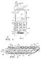
- FIG. 1is a front view of an electronic device according to the preferred embodiment of the invention.
- FIG. 2is a sectional side view of the electronic device shown in FIG. 1 ;
- FIG. 3is a side view of the electronic device shown in FIG. 1 ;
- FIG. 4is a back view of the electronic device shown in FIG. 1 ;
- FIG. 5is a picture of a typical way in which a user would hold the wireless communication device shown in FIGS. 1 and 2 while striking keys;
- FIG. 6is a picture of a typical way in which a user would hold the wireless communication device shown in FIGS. 1 and 2 while listening to a call;
- FIG. 7is an exploded cut away view of another embodiment of a haptic point used in the wireless communication device shown in FIGS. 1 and 2 ;
- FIG. 8is an exploded cut away view of yet another embodiment of a switch used in the wireless communication device shown in FIGS. 1 and 2 ;
- FIG. 9is an exploded cut away view of still another embodiment of a switch used in the wireless communication device shown in FIGS. 1 and 2
- FIG. 10is a block diagram of the electronic device shown in FIGS. 1 and 2 according to the preferred embodiment of the invention.
- FIG. 11is a flow diagram of a method for operating the electronic device shown in FIGS. 1 and 2 according to the preferred embodiment of the invention.
- FIG. 1is a front view of an electronic device according to one embodiment of the invention and FIG. 2 is a sectional side view of the electronic device shown in FIG. 1 .
- the electronic devicecomprises a cellular phone 100 , although it should be understood that it could alternatively comprise other types of electronic devices such as a corded telephone, cordless telephone, hand-held game, Personal Digital Assistant, or pager. Such alternative devices may not include all the elements, such as an antenna or speaker, shown on the cellular phone 100 .
- the cellular phone 100 and all such alternative devicescomprise electronics that performs intelligent operations.
- the cellular phone 100includes a housing 112 .
- the housing 112includes an audio output grid 114 , overlying a speaker 202 attached to a circuit board 204 .
- An antenna 116is provided for receiving and transmitting RF communication signals and is attached to the housing 112 , for example, by a nut 206 .
- a display 118is providing for displaying information, such as stored cellular phone numbers and caller ID information to a user.
- An audio input aperture grid 120is provided for coupling sound including a user's utterances to a microphone 208 .
- the circuit board 204supports and electrically couples circuit components 210 that make up one or more electrical circuits that are part of the cellular phone 100 and provide intelligent operations.
- the circuit board 204also supports the speaker 202 , and the microphone 208 .
- the cellular phone 100includes one or more keys 122 , or buttons, that may control any of several functions such as menu selection, navigation, and data input.
- displaysmay comprise “touch screens” wherein a person may touch a spot on the display with a finger or a stylus for providing information to the electronic device. Such contact by a finger or stylus provides an electrical signal through electrical coupling 216 .
- the keys 122protrude through an opening 123 in the housing 112 .
- the display 118 and keys 122are both cushioned from the housing 112 by a soft material 124 , such as silicon rubber, that dampens any vibration from passing to or from the housing 112 .
- the materialalso serves to prevent dust and moisture from entering into the housing 112 .
- the display 118is also connecting to housing 112 by arms 214 .
- Arms 214provide support to the display 118 by maintaining its position against the soft material 124 .
- Arms 214is substantially rigid along the Z direction (perpendicular to the display plane), but compliant in X, Y directions (in the display plane), allowing the screen 118 to have small lateral displacement to provide haptic feedback to the user.
- An input mechanismsuch as the display 118 and/or the key 122 may be configured for providing active tactile force feedback.
- An electromechanical transducer 218such as a voice-coil based linear vibration motor, a piezoelectric actuator or vibrator, or the like, is mechanically connected directly to the display 118
- an electromechanical transducer 220such as a vibrator, or the like, is mechanically connected directly to the key 122 .
- the electromechanical transducer 218is positioned so the movement provided to the display 118 is in the “x” or “y” direction parallel to the plane of the display 118 (a lateral motion that is perpendicular to the direction in which the user pushes the screen).
- the electromagnetic transducer 218may be mounted on the side of display 118 , as shown in FIG. 2 , or on the back of display 118 (not shown in FIG. 2 ).
- the electromechanical transducer 220may be positioned inside the key 122 as shown in FIG. 2 , or in any of several other positions as described later so that the movement provided to the key 122 is in the “x”, “y” or “z” direction or some combination thereof.
- the electromechanical transducers 218 and 220serve to convert electrical signals to mechanical movement. By having the electromechanical transducers 218 and 220 connected only to the display 118 and key 122 , respectively, little or no vibration is transferred to the housing 112 . Electrical connections to the electromechanical transducers 218 and 220 are made to the circuit board 204 by a twisted pair of leads 222 and 224 , respectively, or flex circuitry, but such wiring transmits substantially no vibrations to the circuit board 204 .
- two virtual keys 126are presented on the display 118 . Although only two virtual keys 126 are shown, it should be understood there could be only one, or several.
- the pressWhen a user presses directly, or with a stylus, on a portion of the touch screen overlying one of the virtual buttons 126 , the press will be detected and in response thereto the electromechanical transducer 218 will be driven causing the electromechanical transducer 218 to emit mechanical energy that is coupled to the touch screen (and through the stylus if used).
- the mechanical energyis felt by the user as one or more impulses (a tactile response).
- the impulse(s)serve to confirm to the user that the intended input has been registered by the cellular phone 100 .
- the electromechanical transducer 218is preferably driven with a signal that includes one or more sharp steps. Driving the electromechanical transducer 218 with a signal that includes one or more sharp steps causes the touch screen 118 to be jolted. Also any other user-defined wave forms could be used to actuate the electromechanical transducer.
- the joltmay comprise information based on intelligent operations performed by the circuit components 210 . If the cellular phone 100 was being held by the user, the jolt would only be felt through the display 18 and not the housing 112 .
- a haptic output(as feedback comprising two or more haptic responses or alerts in different locations (spatially displaced) in response to a single input) to the user.
- a plurality of haptic points 130are positioned on the sides and back of the cellular phone 100 .
- FIG. 4better illustrates the placement of haptic points 130 on the back of cellular phone 100 . It should be understood that these haptic points may alternatively be positioned on only one side, only on the back, only on the sides, on the front, or any combination thereof.
- the number of haptic points 130may be two or more, though four or five on a side provides the best results.
- the haptic points 130are positioned within and cushioned from the housing 112 by a soft material 124 , such as silicon rubber, that dampens any vibration from passing to or from the housing 112 .
- a strip of the soft material 124may be positioned along the sides or back of the cellular phone 100 with two or more haptic points 130 positioned within.
- the haptic points 130ideally would be positioned so each one would provide a vibration to a separate finger.
- FIG. 5illustrates a user holding the cellular phone 100 in a left hand while pushing on a key with a finger on the right hand. Notice how the fingers of the left hand cradle the side of the cellular phone 100 where the haptic points 130 are positioned.
- FIG. 6illustrates a user holding the cellular phone 100 with a left hand to the left ear. Notice how the fingers of the left hand cradle the side of the cellular phone 100 where the haptic points 130 are positioned. By placing the haptic points 130 on both sides of the cellular phone 100 , the user could hold the cellular phone 100 in either hand with the same result. Furthermore, the haptic points 130 would touch the base of the palm 132 providing a similar sensation.
- FIGS. 7 , 8 , and 9show various methods of placing an electromechanical transducer 226 with the haptic points 130 .
- An electromechanical transducer 226such as a voice-coil based vibration motor, a piezoelectric actuator or vibrator, or the like, is mechanically connected directly to the haptic point 130 .
- the electromechanical transducer 226may be positioned inside the haptic point 130 as shown in FIG. 7 , or in any of several other positions as shown in FIGS. 8 and 9 so that the movement provided to the haptic point is in the “x”, “y” or “z” direction or some combination thereof.
- the electromechanical transducer 226serves to convert electrical signals to mechanical movement.
- electromechanical transducer 226By having the electromechanical transducer 226 connected only to the haptic point 130 , little or no vibration is transferred to the housing 112 . Electrical connections to the electromechanical transducer 226 is made to the circuit board 204 by a twisted pair of leads 228 , or flex circuitry, but such wiring transmits substantially no vibrations to the circuit board 204 .
- FIG. 8the electromechanical transducer 226 is connected to the side of the haptic point 130 .
- FIG. 9illustrates yet another embodiment wherein the electromechanical transducer 226 is connected to the bottom of the haptic point 130 .
- the cellular phone 100comprises a transceiver module 502 , a phone processor 504 , an analog-to-digital converter 506 (A/D), an input decoder 508 , a digital-to-analog converter (D/A) 510 , a haptic interface module 512 , a display driver 514 , and a memory module 516 coupled through a digital signal bus 518 .
- the transceiver module 502is coupled through an antenna 116 to free space.
- the A/D 506is coupled to the microphone 208 for receiving audio signals therefrom.
- the display driver 514is coupled to the display 118 .
- the D/A 510is coupled to the speaker 202 .
- the speaker 202is driven by signals output by the D/A 510 .
- An input device 522is coupled to the input decoder 508 .
- the input device 522preferably comprises the keypad 212 , and associated metallization (e.g., interdigitated fingers) on the printed circuit board 204 .
- the input decoder 508serves to identify depressed keys and supply information identifying depressed keys to the phone processor 504 .
- the input decoder 508is preferably adapted to send an interrupt to the phone processor 504 in response to a key press, and thereafter to provide data identifying a depressed key. Identifying information preferably takes the form of a multibit word that is read by the phone processor 504 in a read operation that is triggered by the interrupt.
- the phone processor 504can be programmed to periodically read the input decoder 508 .
- the memory module 516is used to store programs that are executed by the phone processor 504 to control the operation of the cellular phone 100 , including the reading of the input decoder 508 .
- the haptic interface module 512is configured to output pulses of predetermined or user defined amplitude and duration in response to receiving a trigger signal from the phone processor 504 .
- other interface logice.g., address decoding logic
- the phone processor 504is programmed to trigger the haptic interface module 512 in response to a predetermined state as determined by intelligent operations within the phone processor 504 .
- the triggering of the haptic interface module 512can selectively enabled or disabled in accordance with configuration settings that a user can edit.
- the haptic interface module 512is coupled to the electromechanical transducers 226 .
- the electromechanical transducer 226is driven by the output of the haptic interface module 512 .
- the electromechanical transducers 226are preferably driven by a signal that includes at least one approximation of a step function.
- a step functionis a mathematical ideal that no real world circuit can achieve.
- a step functionincludes a broad range of frequencies.
- the electromechanical transducer 226is caused to emit an impulse of mechanical energy that propagates to the haptic point 130 and is felt by a user operating the cellular phone 100 .
- the electromechanical transducer 226is driven by a signal that includes one or more pulses.
- a pulsee.g., a single pulse or a complex waveform, is generated in response to each detected state, where a state refers to a particular situation identified by the phone processor 504 .
- a known pulseis advantageous in that a known pulse generates an impulse of mechanical energy that creates a tactile sensation that simulates the feel of previous states with which the user may be familiar.
- the transceiver module 502 , phone processor 504 , A/D 506 , input decoder 508 , D/A 510 , haptic interface module 512 , display driver 514 , memory 516 , and display driver 514are preferably part of an electric circuit that is embodied in the circuit components 210 , and interconnecting traces of the circuit board 204 .
- a different electric circuitmay be used to drive the electromechanical transducer 226 in order to generate tactile feedback to the haptic points 130 .
- the haptic interface module 512could alternatively be a pulse generator, generating digital pulses of various widths, heights, and/or frequencies based on instructions from the phone processor 504 . Depending on the impedance match to the electromechanical transducer 226 and current sourcing/sinking capability, an amplifier may be needed. Alternatively, the haptic interface module 512 could simply be a current amplifier and pulses would be generated by the phone processor 504 itself. Another possibility is that the haptic interface module 512 comprises multiple DACs which apply analog signals as would be the case if additional audio channels were included.
- FIG. 11is a flow diagram 600 of a method for operating the wireless communication device shown in FIGS. 1 through 10 according to the preferred embodiment of the invention.
- Block 602is a decision block that depends on whether a situation has been detected that requires a haptic response. If not the flow diagram 600 continually loops back and awaits the occurrence of a situation. When a situation is detected, the flow diagram 600 progresses to step 604 in which haptic signal information is retrieved from memory based on the nature of the situation. Once this information is retrieved, the electromechanical transducers 226 are driven to produce tactile feedback.
- haptic responsesFor example, in a pager or cell phone, a message or call from a spouse might cause all the haptic points 130 to vibrate, or a message or call from a boss might cause the haptic points 130 to vibrate in a circular motion around the electronic device, or a message or call from another might cause the haptic points to vibrate repeatedly up one side of the electronic device.
- a message or call from a bossmight cause the haptic points 130 to vibrate in a circular motion around the electronic device, or a message or call from another might cause the haptic points to vibrate repeatedly up one side of the electronic device.
- the use of adjacent multiple vibrators in succession as describedcreates a perceptual illusion of movement (known as the cutaneous rabbit).
- This illusion of movementcould be used to give directional information for navigation.
- the movement along a side, around the electronic device 100 , back and forth,can also be used to convey information, such as to gather attention, create emphasis, and general non-verbal information.
- the electronic device 100can also relay information of its status, such as out of range, low battery, and busy signal. Such information may be valuable while the user is holding the electronic device 100 to his/her ear and cannot readily see information on the screen 118 .
- the multiple localized force feedbackcould also be used for sensorial communication. Instead of sending a voice or text message or a picture or a data file, one could send a particular haptic pattern to other users.
- the patterncould represent a reminder, a certain mood (e.g., thinking of you, love you, missing you, etc.), a particular sensation, or any other user defined contents.
- the terms “comprises”, “comprising”, or any variation thereof,are intended to reference a non-exclusive inclusion, such that a process, method, article, composition or apparatus that comprises a list of elements does not include only those elements recited, but may also include other elements not expressly listed or inherent to such process, method, article, composition or apparatus.
- Other combinations and/or modifications of the above-described structures, arrangements, applications, proportions, elements, materials or components used in the practice of the present invention, in addition to those not specifically recited,may be varied or otherwise particularly adapted by those skilled in the art to specific environments, manufacturing specifications, design parameters or other operating requirements without departing from the general principles of the same.
Landscapes
- Engineering & Computer Science (AREA)
- Theoretical Computer Science (AREA)
- General Engineering & Computer Science (AREA)
- Human Computer Interaction (AREA)
- Physics & Mathematics (AREA)
- General Physics & Mathematics (AREA)
- Computer Hardware Design (AREA)
- Signal Processing (AREA)
- Computer Networks & Wireless Communication (AREA)
- Telephone Function (AREA)
- Telephone Set Structure (AREA)
- User Interface Of Digital Computer (AREA)
Abstract
Description
Claims (22)
Priority Applications (1)
| Application Number | Priority Date | Filing Date | Title |
|---|---|---|---|
| US10/937,821US7148789B2 (en) | 2004-09-09 | 2004-09-09 | Handheld device having multiple localized force feedback |
Applications Claiming Priority (1)
| Application Number | Priority Date | Filing Date | Title |
|---|---|---|---|
| US10/937,821US7148789B2 (en) | 2004-09-09 | 2004-09-09 | Handheld device having multiple localized force feedback |
Publications (2)
| Publication Number | Publication Date |
|---|---|
| US20060049920A1 US20060049920A1 (en) | 2006-03-09 |
| US7148789B2true US7148789B2 (en) | 2006-12-12 |
Family
ID=35995629
Family Applications (1)
| Application Number | Title | Priority Date | Filing Date |
|---|---|---|---|
| US10/937,821Expired - LifetimeUS7148789B2 (en) | 2004-09-09 | 2004-09-09 | Handheld device having multiple localized force feedback |
Country Status (1)
| Country | Link |
|---|---|
| US (1) | US7148789B2 (en) |
Cited By (33)
| Publication number | Priority date | Publication date | Assignee | Title |
|---|---|---|---|---|
| US20060051075A1 (en)* | 2004-09-09 | 2006-03-09 | Hiroshi Wada | Electro-optical device and electronic apparatus |
| US20060055515A1 (en)* | 2004-09-06 | 2006-03-16 | Fujitsu Component Limited | Tactile presenting device |
| US20060152382A1 (en)* | 2003-02-06 | 2006-07-13 | Miska Hiltunen | Method and mobile device for non-visually signaling the state of a mobile device |
| US20060291442A1 (en)* | 2005-06-10 | 2006-12-28 | Duan Mark X | Voice over internet protocol (VoIP) ready computer system and method |
| US20070072601A1 (en)* | 2005-07-29 | 2007-03-29 | Samsung Electronics Co., Ltd. | Method and apparatus for providing information during a call and a mobile device including the same |
| US20090001855A1 (en)* | 2007-06-29 | 2009-01-01 | Artificial Muscle, Inc. | Electroactive polymer transducers for sensory feedback applications |
| US20100123588A1 (en)* | 2008-11-19 | 2010-05-20 | Immersion Corporation | Method and Apparatus for Generating Mood-Based Haptic Feedback |
| US20100156818A1 (en)* | 2008-12-23 | 2010-06-24 | Apple Inc. | Multi touch with multi haptics |
| US20100171715A1 (en)* | 2009-01-08 | 2010-07-08 | Cody George Peterson | Tactile Surface |
| US20110234494A1 (en)* | 2009-10-15 | 2011-09-29 | Cody Peterson | Support-Surface Apparatus to Impart Tactile Feedback |
| US8309870B2 (en) | 2011-01-04 | 2012-11-13 | Cody George Peterson | Leveled touchsurface with planar translational responsiveness to vertical travel |
| US20120326854A1 (en)* | 2011-06-27 | 2012-12-27 | Aac Technologies Holdings Inc. | Apparatus For Providing Haptic Feedback |
| US20130250502A1 (en)* | 2010-10-19 | 2013-09-26 | Nokia Corporation | Display apparatus |
| US8735755B2 (en) | 2011-03-07 | 2014-05-27 | Synaptics Incorporated | Capacitive keyswitch technologies |
| US8847890B2 (en) | 2011-01-04 | 2014-09-30 | Synaptics Incorporated | Leveled touchsurface with planar translational responsiveness to vertical travel |
| US8912458B2 (en) | 2011-01-04 | 2014-12-16 | Synaptics Incorporated | Touchsurface with level and planar translational travel responsiveness |
| US9040851B2 (en) | 2012-08-06 | 2015-05-26 | Synaptics Incorporated | Keycap assembly with an interactive spring mechanism |
| US20150169065A1 (en)* | 2010-04-14 | 2015-06-18 | Samsung Electronics Co., Ltd. | Method and apparatus for processing virtual world |
| US9177733B2 (en) | 2012-08-06 | 2015-11-03 | Synaptics Incorporated | Touchsurface assemblies with linkages |
| US9195058B2 (en) | 2011-03-22 | 2015-11-24 | Parker-Hannifin Corporation | Electroactive polymer actuator lenticular system |
| US9213372B2 (en) | 2013-04-19 | 2015-12-15 | Synaptics Incorporated | Retractable keyboard keys |
| US9218927B2 (en) | 2012-08-06 | 2015-12-22 | Synaptics Incorporated | Touchsurface assembly with level and planar translational responsiveness via a buckling elastic component |
| US9224554B2 (en) | 2013-03-14 | 2015-12-29 | Synaptics Incorporated | Anti-tilt and rotation techniques for a touchsurface assembly having translating keys |
| US9231186B2 (en) | 2009-04-11 | 2016-01-05 | Parker-Hannifin Corporation | Electro-switchable polymer film assembly and use thereof |
| US9324515B2 (en) | 2012-08-06 | 2016-04-26 | Synaptics Incorporated | Touchsurface assembly utilizing magnetically enabled hinge |
| US9349552B2 (en) | 2010-05-24 | 2016-05-24 | Synaptics Incorporated | Touchpad with capacitive force sensing |
| US9553254B2 (en) | 2011-03-01 | 2017-01-24 | Parker-Hannifin Corporation | Automated manufacturing processes for producing deformable polymer devices and films |
| US9590193B2 (en) | 2012-10-24 | 2017-03-07 | Parker-Hannifin Corporation | Polymer diode |
| US9761790B2 (en) | 2012-06-18 | 2017-09-12 | Parker-Hannifin Corporation | Stretch frame for stretching process |
| US9876160B2 (en) | 2012-03-21 | 2018-01-23 | Parker-Hannifin Corporation | Roll-to-roll manufacturing processes for producing self-healing electroactive polymer devices |
| US10997815B2 (en) | 2007-04-30 | 2021-05-04 | Cfph, Llc | Game with player actuated control structure |
| WO2021116249A1 (en) | 2019-12-12 | 2021-06-17 | Actronika | Method for generating tactile sensations located on a surface and haptic interface implementing this method |
| US11169595B2 (en) | 2007-05-29 | 2021-11-09 | Cfph, Llc | Game with hand motion control |
Families Citing this family (51)
| Publication number | Priority date | Publication date | Assignee | Title |
|---|---|---|---|---|
| GB9722766D0 (en) | 1997-10-28 | 1997-12-24 | British Telecomm | Portable computers |
| US7616192B2 (en)* | 2005-07-28 | 2009-11-10 | Avago Technologies Ecbu Ip (Singapore) Pte. Ltd. | Touch device and method for providing tactile feedback |
| KR100755862B1 (en)* | 2006-06-08 | 2007-09-05 | 엘지전자 주식회사 | Mobile terminal and display method in mobile terminal |
| US8564544B2 (en) | 2006-09-06 | 2013-10-22 | Apple Inc. | Touch screen device, method, and graphical user interface for customizing display of content category icons |
| US20080068334A1 (en) | 2006-09-14 | 2008-03-20 | Immersion Corporation | Localized Haptic Feedback |
| KR101145921B1 (en)* | 2006-12-13 | 2012-05-15 | 엘지전자 주식회사 | A mobile terminal, a mobile communication terminal and a method for providing a user interface using the same |
| US7844915B2 (en) | 2007-01-07 | 2010-11-30 | Apple Inc. | Application programming interfaces for scrolling operations |
| US8761846B2 (en)* | 2007-04-04 | 2014-06-24 | Motorola Mobility Llc | Method and apparatus for controlling a skin texture surface on a device |
| US20090015547A1 (en)* | 2007-07-12 | 2009-01-15 | Franz Roger L | Electronic Device with Physical Alert |
| US8509854B2 (en) | 2007-09-18 | 2013-08-13 | Lg Electronics Inc. | Mobile terminal and method of controlling operation of the same |
| US20090085879A1 (en)* | 2007-09-28 | 2009-04-02 | Motorola, Inc. | Electronic device having rigid input surface with piezoelectric haptics and corresponding method |
| US20090091479A1 (en)* | 2007-10-04 | 2009-04-09 | Motorola, Inc. | Keypad haptic communication |
| US9857872B2 (en)* | 2007-12-31 | 2018-01-02 | Apple Inc. | Multi-touch display screen with localized tactile feedback |
| KR101474426B1 (en)* | 2008-01-22 | 2014-12-19 | 엘지전자 주식회사 | Mobile terminal and its method for controlling of vibrator |
| JP5227769B2 (en)* | 2008-12-05 | 2013-07-03 | ソニーモバイルコミュニケーションズ, エービー | Mobile terminal and computer program |
| US9489046B2 (en)* | 2009-05-04 | 2016-11-08 | Immersion Corporation | Method and apparatus for providing haptic feedback to non-input locations |
| GB2470418A (en)* | 2009-05-22 | 2010-11-24 | Nec Corp | Haptic information delivery |
| US8441465B2 (en) | 2009-08-17 | 2013-05-14 | Nokia Corporation | Apparatus comprising an optically transparent sheet and related methods |
| US8390594B2 (en) | 2009-08-18 | 2013-03-05 | Immersion Corporation | Haptic feedback using composite piezoelectric actuator |
| KR100986681B1 (en)* | 2010-05-06 | 2010-10-08 | (주)이미지스테크놀로지 | Apparatus for controlling multi acutator drive for generating touch feeling |
| US9030308B1 (en)* | 2010-07-02 | 2015-05-12 | Amazon Technologies, Inc. | Piezoelectric haptic actuator integration |
| WO2012090031A1 (en)* | 2010-12-31 | 2012-07-05 | Nokia Corporation | A display apparatus producing audio and haptic output |
| US20120188065A1 (en)* | 2011-01-25 | 2012-07-26 | Harris Corporation | Methods and systems for indicating device status |
| US8624857B2 (en)* | 2011-02-09 | 2014-01-07 | Texas Instruments Incorporated | Haptics effect controller architecture and instruction set |
| US20130335211A1 (en)* | 2011-02-24 | 2013-12-19 | Kyocera Corporation | Electronic device |
| US20130033366A1 (en)* | 2011-08-01 | 2013-02-07 | Mcdonough Colin Albright | Method and system for providing haptic feedback of variable intensity |
| FR2986342B1 (en)* | 2012-01-31 | 2014-02-21 | Inst Nat Rech Inf Automat | INTERACTION DEVICE FOR CONTROLLING A TOUCH AND PREHENSION ELEMENT OF MULTIDIMENSIONAL VIRTUAL OBJECTS. |
| US9426905B2 (en) | 2012-03-02 | 2016-08-23 | Microsoft Technology Licensing, Llc | Connection device for computing devices |
| US9298236B2 (en) | 2012-03-02 | 2016-03-29 | Microsoft Technology Licensing, Llc | Multi-stage power adapter configured to provide a first power level upon initial connection of the power adapter to the host device and a second power level thereafter upon notification from the host device to the power adapter |
| US9360893B2 (en) | 2012-03-02 | 2016-06-07 | Microsoft Technology Licensing, Llc | Input device writing surface |
| US9075566B2 (en) | 2012-03-02 | 2015-07-07 | Microsoft Technoogy Licensing, LLC | Flexible hinge spine |
| US9460029B2 (en) | 2012-03-02 | 2016-10-04 | Microsoft Technology Licensing, Llc | Pressure sensitive keys |
| US9064654B2 (en) | 2012-03-02 | 2015-06-23 | Microsoft Technology Licensing, Llc | Method of manufacturing an input device |
| USRE48963E1 (en) | 2012-03-02 | 2022-03-08 | Microsoft Technology Licensing, Llc | Connection device for computing devices |
| US9870066B2 (en) | 2012-03-02 | 2018-01-16 | Microsoft Technology Licensing, Llc | Method of manufacturing an input device |
| JP6248928B2 (en)* | 2012-04-27 | 2017-12-20 | 株式会社ニコン | Electronics |
| US20130300590A1 (en) | 2012-05-14 | 2013-11-14 | Paul Henry Dietz | Audio Feedback |
| US10031556B2 (en) | 2012-06-08 | 2018-07-24 | Microsoft Technology Licensing, Llc | User experience adaptation |
| US9019615B2 (en) | 2012-06-12 | 2015-04-28 | Microsoft Technology Licensing, Llc | Wide field-of-view virtual image projector |
| US8952892B2 (en) | 2012-11-01 | 2015-02-10 | Microsoft Corporation | Input location correction tables for input panels |
| US8949735B2 (en) | 2012-11-02 | 2015-02-03 | Google Inc. | Determining scroll direction intent |
| CN105026122B (en)* | 2013-02-01 | 2017-09-29 | 胡斯华纳有限公司 | With the measurement based on inertia and the power-equipment of guiding |
| US9304549B2 (en) | 2013-03-28 | 2016-04-05 | Microsoft Technology Licensing, Llc | Hinge mechanism for rotatable component attachment |
| US9520036B1 (en)* | 2013-09-18 | 2016-12-13 | Amazon Technologies, Inc. | Haptic output generation with dynamic feedback control |
| US20150084875A1 (en)* | 2013-09-26 | 2015-03-26 | Min Liu | Enhanced haptic feedback for handheld mobile computing devices |
| US11117204B2 (en) | 2014-05-06 | 2021-09-14 | Husqvarna Ab | Power tool |
| US9696806B2 (en)* | 2014-07-02 | 2017-07-04 | Immersion Corporation | Systems and methods for multi-output electrostatic haptic effects |
| US20160086456A1 (en)* | 2014-09-24 | 2016-03-24 | Apple Inc. | Electronic Device With Electrically Controlled Button Indicator |
| DE102016124275A1 (en)* | 2016-12-13 | 2018-06-14 | Brose Fahrzeugteile Gmbh & Co. Kommanditgesellschaft, Bamberg | Method for controlling a motor-driven closure element arrangement of a motor vehicle |
| US10375930B1 (en)* | 2017-07-07 | 2019-08-13 | Chad R. James | Animal training device that controls stimulus using proportional pressure-based input |
| US10921892B2 (en)* | 2019-02-04 | 2021-02-16 | Subpac, Inc. | Personalized tactile output |
Citations (10)
| Publication number | Priority date | Publication date | Assignee | Title |
|---|---|---|---|---|
| US6230135B1 (en) | 1999-02-02 | 2001-05-08 | Shannon A. Ramsay | Tactile communication apparatus and method |
| US20010019324A1 (en) | 1998-06-23 | 2001-09-06 | Immersion Corporation | Interface device with tactile feedback button |
| US6326901B1 (en) | 1995-10-25 | 2001-12-04 | Gilbert Rene Gonzales | Tactile communication device and method |
| US20020033795A1 (en) | 2000-01-19 | 2002-03-21 | Shahoian Erik J. | Haptic interface for laptop computers and other portable devices |
| US20020075135A1 (en) | 2000-12-20 | 2002-06-20 | New Transducers Limited | Multi-functional vibro-acoustic device |
| US6429846B2 (en) | 1998-06-23 | 2002-08-06 | Immersion Corporation | Haptic feedback for touchpads and other touch controls |
| US20030174121A1 (en)* | 2002-01-28 | 2003-09-18 | Sony Corporation | Mobile apparatus having tactile feedback function |
| US6710518B2 (en) | 2002-05-31 | 2004-03-23 | Motorola, Inc. | Manually operable electronic apparatus |
| US6819939B2 (en)* | 2001-03-21 | 2004-11-16 | Nec Viewtechnology, Ltd. | Cellular phone with high-quality sound reproduction capability |
| US7006641B1 (en)* | 1999-04-14 | 2006-02-28 | Matsushita Electric Industrial Co., Ltd. | Driving circuit, electro-mechanical-acoustic transducer, and portable terminal apparatus |
Family Cites Families (4)
| Publication number | Priority date | Publication date | Assignee | Title |
|---|---|---|---|---|
| US19324A (en)* | 1858-02-09 | Improvement in cotton-gins | ||
| US174121A (en)* | 1876-02-29 | Improvement in churn-powers | ||
| US75135A (en)* | 1868-03-03 | ellston | ||
| US33795A (en)* | 1861-11-26 | Improvement in retrackers for railroad-cars |
- 2004
- 2004-09-09USUS10/937,821patent/US7148789B2/ennot_activeExpired - Lifetime
Patent Citations (10)
| Publication number | Priority date | Publication date | Assignee | Title |
|---|---|---|---|---|
| US6326901B1 (en) | 1995-10-25 | 2001-12-04 | Gilbert Rene Gonzales | Tactile communication device and method |
| US20010019324A1 (en) | 1998-06-23 | 2001-09-06 | Immersion Corporation | Interface device with tactile feedback button |
| US6429846B2 (en) | 1998-06-23 | 2002-08-06 | Immersion Corporation | Haptic feedback for touchpads and other touch controls |
| US6230135B1 (en) | 1999-02-02 | 2001-05-08 | Shannon A. Ramsay | Tactile communication apparatus and method |
| US7006641B1 (en)* | 1999-04-14 | 2006-02-28 | Matsushita Electric Industrial Co., Ltd. | Driving circuit, electro-mechanical-acoustic transducer, and portable terminal apparatus |
| US20020033795A1 (en) | 2000-01-19 | 2002-03-21 | Shahoian Erik J. | Haptic interface for laptop computers and other portable devices |
| US20020075135A1 (en) | 2000-12-20 | 2002-06-20 | New Transducers Limited | Multi-functional vibro-acoustic device |
| US6819939B2 (en)* | 2001-03-21 | 2004-11-16 | Nec Viewtechnology, Ltd. | Cellular phone with high-quality sound reproduction capability |
| US20030174121A1 (en)* | 2002-01-28 | 2003-09-18 | Sony Corporation | Mobile apparatus having tactile feedback function |
| US6710518B2 (en) | 2002-05-31 | 2004-03-23 | Motorola, Inc. | Manually operable electronic apparatus |
Non-Patent Citations (1)
| Title |
|---|
| Poupyrev et al., Touch Engine: A tactile Display for Handheld Devices, article, Conference on Human Factors in Computing Systems, Minneapolis, MN, Apr. 20-25, 2002, pp. 644-645. |
Cited By (58)
| Publication number | Priority date | Publication date | Assignee | Title |
|---|---|---|---|---|
| US20060152382A1 (en)* | 2003-02-06 | 2006-07-13 | Miska Hiltunen | Method and mobile device for non-visually signaling the state of a mobile device |
| US7439872B2 (en)* | 2003-02-06 | 2008-10-21 | Nokia Corporation | Method and mobile device for non-visually signaling the state of a mobile device |
| US20060055515A1 (en)* | 2004-09-06 | 2006-03-16 | Fujitsu Component Limited | Tactile presenting device |
| US7525415B2 (en)* | 2004-09-06 | 2009-04-28 | Fujitsu Component Limited | Tactile presenting device |
| US7798284B2 (en)* | 2004-09-09 | 2010-09-21 | Seiko Epson Corporation | Electro-optical device and electronic apparatus |
| US20060051075A1 (en)* | 2004-09-09 | 2006-03-09 | Hiroshi Wada | Electro-optical device and electronic apparatus |
| US20060291442A1 (en)* | 2005-06-10 | 2006-12-28 | Duan Mark X | Voice over internet protocol (VoIP) ready computer system and method |
| US20070072601A1 (en)* | 2005-07-29 | 2007-03-29 | Samsung Electronics Co., Ltd. | Method and apparatus for providing information during a call and a mobile device including the same |
| US8027705B2 (en)* | 2005-07-29 | 2011-09-27 | Samsung Electronics Co., Ltd. | Method and apparatus for providing information during a call and a mobile device including the same |
| US10997815B2 (en) | 2007-04-30 | 2021-05-04 | Cfph, Llc | Game with player actuated control structure |
| US11169595B2 (en) | 2007-05-29 | 2021-11-09 | Cfph, Llc | Game with hand motion control |
| US20090001855A1 (en)* | 2007-06-29 | 2009-01-01 | Artificial Muscle, Inc. | Electroactive polymer transducers for sensory feedback applications |
| US7952261B2 (en)* | 2007-06-29 | 2011-05-31 | Bayer Materialscience Ag | Electroactive polymer transducers for sensory feedback applications |
| US9425383B2 (en) | 2007-06-29 | 2016-08-23 | Parker-Hannifin Corporation | Method of manufacturing electroactive polymer transducers for sensory feedback applications |
| US8390439B2 (en)* | 2008-11-19 | 2013-03-05 | Immersion Corporation | Method and apparatus for generating mood-based haptic feedback |
| US8004391B2 (en)* | 2008-11-19 | 2011-08-23 | Immersion Corporation | Method and apparatus for generating mood-based haptic feedback |
| US10289201B2 (en)* | 2008-11-19 | 2019-05-14 | Immersion Corporation | Method and apparatus for generating mood-based haptic feedback |
| US9841816B2 (en) | 2008-11-19 | 2017-12-12 | Immersion Corporation | Method and apparatus for generating mood-based haptic feedback |
| US20120001749A1 (en)* | 2008-11-19 | 2012-01-05 | Immersion Corporation | Method and Apparatus for Generating Mood-Based Haptic Feedback |
| US20100123588A1 (en)* | 2008-11-19 | 2010-05-20 | Immersion Corporation | Method and Apparatus for Generating Mood-Based Haptic Feedback |
| US9235267B2 (en) | 2008-12-23 | 2016-01-12 | Apple Inc. | Multi touch with multi haptics |
| US20100156818A1 (en)* | 2008-12-23 | 2010-06-24 | Apple Inc. | Multi touch with multi haptics |
| US8686952B2 (en) | 2008-12-23 | 2014-04-01 | Apple Inc. | Multi touch with multi haptics |
| US20110096013A1 (en)* | 2009-01-08 | 2011-04-28 | Krumpelman Douglas M | Techniques for tactile feedback technology |
| US8760413B2 (en) | 2009-01-08 | 2014-06-24 | Synaptics Incorporated | Tactile surface |
| US20100171715A1 (en)* | 2009-01-08 | 2010-07-08 | Cody George Peterson | Tactile Surface |
| US9231186B2 (en) | 2009-04-11 | 2016-01-05 | Parker-Hannifin Corporation | Electro-switchable polymer film assembly and use thereof |
| US20110234494A1 (en)* | 2009-10-15 | 2011-09-29 | Cody Peterson | Support-Surface Apparatus to Impart Tactile Feedback |
| US10068728B2 (en) | 2009-10-15 | 2018-09-04 | Synaptics Incorporated | Touchpad with capacitive force sensing |
| US8624839B2 (en) | 2009-10-15 | 2014-01-07 | Synaptics Incorporated | Support-surface apparatus to impart tactile feedback |
| US9952668B2 (en)* | 2010-04-14 | 2018-04-24 | Samsung Electronics Co., Ltd. | Method and apparatus for processing virtual world |
| US20150169065A1 (en)* | 2010-04-14 | 2015-06-18 | Samsung Electronics Co., Ltd. | Method and apparatus for processing virtual world |
| US9349552B2 (en) | 2010-05-24 | 2016-05-24 | Synaptics Incorporated | Touchpad with capacitive force sensing |
| US10638617B2 (en)* | 2010-10-19 | 2020-04-28 | Nokia Technologies Oy | Display apparatus |
| US20130250502A1 (en)* | 2010-10-19 | 2013-09-26 | Nokia Corporation | Display apparatus |
| US8912458B2 (en) | 2011-01-04 | 2014-12-16 | Synaptics Incorporated | Touchsurface with level and planar translational travel responsiveness |
| US8309870B2 (en) | 2011-01-04 | 2012-11-13 | Cody George Peterson | Leveled touchsurface with planar translational responsiveness to vertical travel |
| US8847890B2 (en) | 2011-01-04 | 2014-09-30 | Synaptics Incorporated | Leveled touchsurface with planar translational responsiveness to vertical travel |
| US9430050B2 (en) | 2011-01-04 | 2016-08-30 | Synaptics Incorporated | Touchsurface with level and planar translational travel responsiveness |
| US9553254B2 (en) | 2011-03-01 | 2017-01-24 | Parker-Hannifin Corporation | Automated manufacturing processes for producing deformable polymer devices and films |
| US8927890B2 (en) | 2011-03-07 | 2015-01-06 | Synaptics Incorporated | Capacitive keyswitch technologies |
| US8735755B2 (en) | 2011-03-07 | 2014-05-27 | Synaptics Incorporated | Capacitive keyswitch technologies |
| US9195058B2 (en) | 2011-03-22 | 2015-11-24 | Parker-Hannifin Corporation | Electroactive polymer actuator lenticular system |
| US20120326854A1 (en)* | 2011-06-27 | 2012-12-27 | Aac Technologies Holdings Inc. | Apparatus For Providing Haptic Feedback |
| US8830041B2 (en)* | 2011-06-27 | 2014-09-09 | Aac Acoustic Technologies (Shenzhen) Co., Ltd. | Apparatus for providing haptic feedback |
| US9876160B2 (en) | 2012-03-21 | 2018-01-23 | Parker-Hannifin Corporation | Roll-to-roll manufacturing processes for producing self-healing electroactive polymer devices |
| US9761790B2 (en) | 2012-06-18 | 2017-09-12 | Parker-Hannifin Corporation | Stretch frame for stretching process |
| US9324515B2 (en) | 2012-08-06 | 2016-04-26 | Synaptics Incorporated | Touchsurface assembly utilizing magnetically enabled hinge |
| US9040851B2 (en) | 2012-08-06 | 2015-05-26 | Synaptics Incorporated | Keycap assembly with an interactive spring mechanism |
| US9177733B2 (en) | 2012-08-06 | 2015-11-03 | Synaptics Incorporated | Touchsurface assemblies with linkages |
| US9218927B2 (en) | 2012-08-06 | 2015-12-22 | Synaptics Incorporated | Touchsurface assembly with level and planar translational responsiveness via a buckling elastic component |
| US9590193B2 (en) | 2012-10-24 | 2017-03-07 | Parker-Hannifin Corporation | Polymer diode |
| US9224554B2 (en) | 2013-03-14 | 2015-12-29 | Synaptics Incorporated | Anti-tilt and rotation techniques for a touchsurface assembly having translating keys |
| US9384919B2 (en) | 2013-03-14 | 2016-07-05 | Synaptics Incorporated | Touchsurface assembly having key guides formed in a sheet metal component |
| US9490087B2 (en) | 2013-04-19 | 2016-11-08 | Synaptics Incorporated | Retractable keyboard keys |
| US9213372B2 (en) | 2013-04-19 | 2015-12-15 | Synaptics Incorporated | Retractable keyboard keys |
| WO2021116249A1 (en) | 2019-12-12 | 2021-06-17 | Actronika | Method for generating tactile sensations located on a surface and haptic interface implementing this method |
| FR3104762A1 (en) | 2019-12-12 | 2021-06-18 | Actronika | Method for generating tactile sensations localized on a surface and haptic interface implementing this method |
Also Published As
| Publication number | Publication date |
|---|---|
| US20060049920A1 (en) | 2006-03-09 |
Similar Documents
| Publication | Publication Date | Title |
|---|---|---|
| US7148789B2 (en) | Handheld device having multiple localized force feedback | |
| US20060028428A1 (en) | Handheld device having localized force feedback | |
| EP1547168B1 (en) | Manually operable electronic apparatus | |
| US7468573B2 (en) | Method of providing tactile feedback | |
| US20080100568A1 (en) | Electronic device providing tactile feedback | |
| US9865142B2 (en) | Piezoelectric user interface | |
| US20170108931A1 (en) | Multiple mode haptic feedback system | |
| KR101463821B1 (en) | Portable terminal | |
| CN101523329A (en) | Multi-mode haptic feedback system | |
| US20090091479A1 (en) | Keypad haptic communication | |
| JP4770164B2 (en) | Piezoelectric support structure, piezoelectric body mounting method, input device with tactile function, and electronic device | |
| JP2008225690A (en) | Vibration body, tactile sense function-equipped input device, and electronic equipment | |
| JP2007052785A (en) | Touch screen assembly, terminal and terminal control method | |
| US8013266B2 (en) | Key button and key assembly using the key button and portable electronic device using the keypad assembly | |
| JP2006119849A (en) | Piezoelectric body support structure, piezoelectric body mounting method, input device with tactile function and electronic instrument | |
| CN222050798U (en) | User interface unit for electronic device and electronic device | |
| CN1333416C (en) | Electronic device and its keyboard | |
| JP5528831B2 (en) | Portable electronic devices | |
| US20050263377A1 (en) | Electronic device and keyboard thereof | |
| CN2446575Y (en) | Multi-function operation buttons for handheld products |
Legal Events
| Date | Code | Title | Description |
|---|---|---|---|
| AS | Assignment | Owner name:MOTOROLA, INC., ILLINOIS Free format text:ASSIGNMENT OF ASSIGNORS INTEREST;ASSIGNORS:SADLER, DANIEL J.;CAINE, MICHAEL E.;CHANG, ANGELA;AND OTHERS;REEL/FRAME:015783/0561;SIGNING DATES FROM 20040831 TO 20040909 | |
| STCF | Information on status: patent grant | Free format text:PATENTED CASE | |
| FPAY | Fee payment | Year of fee payment:4 | |
| AS | Assignment | Owner name:MOTOROLA MOBILITY, INC, ILLINOIS Free format text:ASSIGNMENT OF ASSIGNORS INTEREST;ASSIGNOR:MOTOROLA, INC;REEL/FRAME:025673/0558 Effective date:20100731 | |
| AS | Assignment | Owner name:MOTOROLA MOBILITY LLC, ILLINOIS Free format text:CHANGE OF NAME;ASSIGNOR:MOTOROLA MOBILITY, INC.;REEL/FRAME:029216/0282 Effective date:20120622 | |
| FPAY | Fee payment | Year of fee payment:8 | |
| AS | Assignment | Owner name:GOOGLE TECHNOLOGY HOLDINGS LLC, CALIFORNIA Free format text:ASSIGNMENT OF ASSIGNORS INTEREST;ASSIGNOR:MOTOROLA MOBILITY LLC;REEL/FRAME:034419/0001 Effective date:20141028 | |
| MAFP | Maintenance fee payment | Free format text:PAYMENT OF MAINTENANCE FEE, 12TH YEAR, LARGE ENTITY (ORIGINAL EVENT CODE: M1553) Year of fee payment:12 |