US7148777B2 - Permanent magnet assembly - Google Patents
Permanent magnet assemblyDownload PDFInfo
- Publication number
- US7148777B2 US7148777B2US11/050,109US5010905AUS7148777B2US 7148777 B2US7148777 B2US 7148777B2US 5010905 AUS5010905 AUS 5010905AUS 7148777 B2US7148777 B2US 7148777B2
- Authority
- US
- United States
- Prior art keywords
- face
- permanent magnet
- radial
- faces
- lateral
- Prior art date
- Legal status (The legal status is an assumption and is not a legal conclusion. Google has not performed a legal analysis and makes no representation as to the accuracy of the status listed.)
- Expired - Lifetime, expires
Links
- 230000005291magnetic effectEffects0.000claimsabstractdescription141
- 230000004907fluxEffects0.000claimsdescription396
- 230000000903blocking effectEffects0.000claimsdescription202
- 239000013598vectorSubstances0.000claimsdescription124
- 230000005415magnetizationEffects0.000claimsdescription116
- 239000000463materialSubstances0.000claimsdescription74
- 239000007787solidSubstances0.000claimsdescription63
- 238000010276constructionMethods0.000description13
- 238000005520cutting processMethods0.000description9
- 238000004519manufacturing processMethods0.000description9
- 239000012141concentrateSubstances0.000description6
- 230000000712assemblyEffects0.000description5
- 238000000429assemblyMethods0.000description5
- 230000008901benefitEffects0.000description5
- 229910001209Low-carbon steelInorganic materials0.000description4
- 238000003754machiningMethods0.000description4
- 230000008878couplingEffects0.000description3
- 238000010168coupling processMethods0.000description3
- 238000005859coupling reactionMethods0.000description3
- 238000005057refrigerationMethods0.000description3
- 230000001154acute effectEffects0.000description2
- 229910045601alloyInorganic materials0.000description2
- 239000000956alloySubstances0.000description2
- 239000002131composite materialSubstances0.000description2
- 239000013529heat transfer fluidSubstances0.000description2
- 238000005304joiningMethods0.000description2
- 229910052751metalInorganic materials0.000description2
- 239000002184metalSubstances0.000description2
- 150000002739metalsChemical class0.000description2
- 238000009428plumbingMethods0.000description2
- 230000007704transitionEffects0.000description2
- 229910001313Cobalt-iron alloyInorganic materials0.000description1
- 241001061076Melanonus zugmayeriSpecies0.000description1
- ABEXMJLMICYACI-UHFFFAOYSA-N[V].[Co].[Fe]Chemical compound[V].[Co].[Fe]ABEXMJLMICYACI-UHFFFAOYSA-N0.000description1
- 150000001875compoundsChemical class0.000description1
- 238000001816coolingMethods0.000description1
- 230000000694effectsEffects0.000description1
- 210000003746featherAnatomy0.000description1
- 230000005294ferromagnetic effectEffects0.000description1
- 238000010438heat treatmentMethods0.000description1
- 238000002955isolationMethods0.000description1
- 239000000696magnetic materialSubstances0.000description1
- 230000013011matingEffects0.000description1
- 229910001172neodymium magnetInorganic materials0.000description1
- 230000005298paramagnetic effectEffects0.000description1
- 238000003825pressingMethods0.000description1
Images


Classifications
- F—MECHANICAL ENGINEERING; LIGHTING; HEATING; WEAPONS; BLASTING
- F25—REFRIGERATION OR COOLING; COMBINED HEATING AND REFRIGERATION SYSTEMS; HEAT PUMP SYSTEMS; MANUFACTURE OR STORAGE OF ICE; LIQUEFACTION SOLIDIFICATION OF GASES
- F25B—REFRIGERATION MACHINES, PLANTS OR SYSTEMS; COMBINED HEATING AND REFRIGERATION SYSTEMS; HEAT PUMP SYSTEMS
- F25B21/00—Machines, plants or systems, using electric or magnetic effects
- H—ELECTRICITY
- H01—ELECTRIC ELEMENTS
- H01F—MAGNETS; INDUCTANCES; TRANSFORMERS; SELECTION OF MATERIALS FOR THEIR MAGNETIC PROPERTIES
- H01F7/00—Magnets
- H01F7/02—Permanent magnets [PM]
- H—ELECTRICITY
- H01—ELECTRIC ELEMENTS
- H01F—MAGNETS; INDUCTANCES; TRANSFORMERS; SELECTION OF MATERIALS FOR THEIR MAGNETIC PROPERTIES
- H01F7/00—Magnets
- H01F7/02—Permanent magnets [PM]
- H01F7/0205—Magnetic circuits with PM in general
- F—MECHANICAL ENGINEERING; LIGHTING; HEATING; WEAPONS; BLASTING
- F25—REFRIGERATION OR COOLING; COMBINED HEATING AND REFRIGERATION SYSTEMS; HEAT PUMP SYSTEMS; MANUFACTURE OR STORAGE OF ICE; LIQUEFACTION SOLIDIFICATION OF GASES
- F25B—REFRIGERATION MACHINES, PLANTS OR SYSTEMS; COMBINED HEATING AND REFRIGERATION SYSTEMS; HEAT PUMP SYSTEMS
- F25B2321/00—Details of machines, plants or systems, using electric or magnetic effects
- F25B2321/002—Details of machines, plants or systems, using electric or magnetic effects by using magneto-caloric effects
- F25B2321/0021—Details of machines, plants or systems, using electric or magnetic effects by using magneto-caloric effects with a static fixed magnet
- F—MECHANICAL ENGINEERING; LIGHTING; HEATING; WEAPONS; BLASTING
- F25—REFRIGERATION OR COOLING; COMBINED HEATING AND REFRIGERATION SYSTEMS; HEAT PUMP SYSTEMS; MANUFACTURE OR STORAGE OF ICE; LIQUEFACTION SOLIDIFICATION OF GASES
- F25B—REFRIGERATION MACHINES, PLANTS OR SYSTEMS; COMBINED HEATING AND REFRIGERATION SYSTEMS; HEAT PUMP SYSTEMS
- F25B2321/00—Details of machines, plants or systems, using electric or magnetic effects
- F25B2321/002—Details of machines, plants or systems, using electric or magnetic effects by using magneto-caloric effects
- F25B2321/0023—Details of machines, plants or systems, using electric or magnetic effects by using magneto-caloric effects with modulation, influencing or enhancing an existing magnetic field
- Y—GENERAL TAGGING OF NEW TECHNOLOGICAL DEVELOPMENTS; GENERAL TAGGING OF CROSS-SECTIONAL TECHNOLOGIES SPANNING OVER SEVERAL SECTIONS OF THE IPC; TECHNICAL SUBJECTS COVERED BY FORMER USPC CROSS-REFERENCE ART COLLECTIONS [XRACs] AND DIGESTS
- Y02—TECHNOLOGIES OR APPLICATIONS FOR MITIGATION OR ADAPTATION AGAINST CLIMATE CHANGE
- Y02B—CLIMATE CHANGE MITIGATION TECHNOLOGIES RELATED TO BUILDINGS, e.g. HOUSING, HOUSE APPLIANCES OR RELATED END-USER APPLICATIONS
- Y02B30/00—Energy efficient heating, ventilation or air conditioning [HVAC]
Definitions
- This inventionrelates generally to magnets, and more particularly to permanent magnet assemblies adapted to provide a time-varying magnetic field to an annular region.
- Permanent magnetshave been used for many years and for many purposes. However, new applications of permanent magnets are driving the development of increasingly sophisticated permanent magnet assemblies. A permanent magnet assembly that can produce a high amplitude magnetic field intensity across a gap is of particular interest, especially in applications of magnetocaloric materials. Magnetocaloric materials near a transition from a ferromagnetic state to a paramagnetic state will warm when magnetized and cool when demagnetized. An apparatus that applies a time-varying magnetic field to magnetocaloric materials can be used to provide heating or cooling, for example in a magnetic refrigerator.
- a magnet assembly that produces a magnetic field intensity across a gapcan be used to apply a time-varying magnetic field to magnetocaloric materials by moving the magnetocaloric materials in and out of the gap. This can be accomplished, for example, by moving the magnetocaloric materials relative to a stationary magnetic assembly, or by moving a magnet assembly relative to stationary magnetocaloric materials.
- Movement of magnetocaloric material relative to a magnet assemblycan be accomplished through rotational or translational motion.
- One approachis to arrange magnetocaloric material in a stationary annular (ring-shaped) structure, and then to rotate a permanent magnet assembly around the ring.
- Another approachis to arrange magnetocaloric material in an annular structure partially surrounded by a stationary permanent magnet assembly, and then to rotate the annular structure containing the magnetocaloric material.
- a permanent magnet assembly specially adapted to provide a time-varying magnetic field to an annular regionis of interest, for applications including, but not limited to, magnetic refrigeration.
- a permanent magnet assembly according to the present inventionis adapted to generate a strong magnetic field across an air gap and to provide a time-varying magnetic field to an annular region having a central axis while minimizing the volume, mass, and fabrication cost of such an assembly.
- a permanent magnet assembly according to the inventioncan be especially well suited for a rotating bed or rotating magnet magnetic refrigerator.
- a permanent magnet assemblycan allow constant access to the air gap or annular region from one side.
- Thiscan enable components of a magnetic refrigerator, such as beds containing magnetocaloric material and heat transfer fluid plumbing, to be stationary and positioned within the air gap or annular region while the magnet assembly rotates.
- the magnet assemblycan be made stationary, while components of a magnetic refrigerator, such as beds containing magnetocaloric material and heat transfer fluid plumbing, rotate within the annular region.
- a permanent magnet assembly according to the inventionincludes a plurality of magnet blocks made of sintered magnet material, each magnet block having its own magnetic field vector.
- the magnet blocksare positioned to direct the path of flux lines within the assembly along a loop that spans the incorporated air gap.
- a permanent magnet assemblycan use magnet blocks in as close to their assintered form as possible, to minimize the number of cutting and grinding operations and reduce the amount of scrap material, by reducing the need for precisely machined permanent magnets.
- Some or all of the permanent magnet portions of such a magnet assemblycan be arc-shaped with a rectangular cross section or generally rectangular in shape, in either case with an orthogonal magnetization vector to minimize production costs.
- This geometrycan be especially well suited to the manufacture of sintered NdFeB magnets by current pressing methods, and the relatively low number of magnet mating surfaces can reduce the number of precision grinding operations that might otherwise be required.
- a permanent magnet assembly according to the inventioncan include one or more features to optimize the assembly for a particular application.
- a permanent magnet assembly according to the inventioncan include one or more pole pieces, for example to focus and concentrate magnetic flux into the air gap.
- a permanent magnet assembly according to the inventioncan include one or more blocking magnets, for example to concentrate flux or minimize stray flux.
- a permanent magnet assembly according to the inventionmay include a flux containment jacket or one or more flux containment sheaths, for example to minimize flux loss outside the flux loop.
- Precisely machined structures used in a magnet assembly according to the inventionmay have surfaces that benefit from close tolerances to allow these surfaces to nest closely together with other components of a magnetic refrigerator, such as containers of magnetocaloric materials.
- a magnetic refrigeratorsuch as containers of magnetocaloric materials.
- a permanent magnet assembly according to the inventioncan provide axial gap flux (magnetic flux through the air gap in a direction parallel to the central axis of an annular region).
- axial gap fluxmagnetic flux through the air gap in a direction parallel to the central axis of an annular region.
- an interior flux return pathlocated inside the annular region
- an exterior flux pathlocated outside the annular region
- such a permanent magnet assemblycan provide radial gap flux (magnetic flux through the air gap in a direction normal to the central axis of an annular region).
- radial gap fluxelectromagnetic flux through the air gap in a direction normal to the central axis of an annular region.
- an upper flux return pathlocated above the annular region
- a lower flux pathlocated below the annular region
- a preferred embodiment of a permanent magnet assemblyprovides axial gap flux with an exterior flux return path, and includes straight-segment configuration features.
- This preferred embodimentincludes two upper radial permanent magnets, two lower radial permanent magnets, two central axial permanent magnets, with two upper axial permanent magnets and two lower axial permanent magnets surrounding an air gap, arranged to form a magnetic loop to subject the air gap to a high axial magnetic field.
- the preferred embodimentmay include upper and lower circumferential blocking magnets and upper and lower radial blocking magnets that can improve the field generation characteristics without greatly increasing the cost, although this is not required.
- An alternative permanent magnet assemblyprovides axial gap flux with an exterior flux return path, and includes arc-shaped curved block magnets having a rectangular cross-section.
- This alternative permanent magnet assemblyincludes an arc-shaped central axial permanent magnet, arc-shaped upper and lower radial permanent magnets, and arc-shaped upper and lower axial permanent magnets surrounding an arc-shaped air gap, arranged to form a magnetic loop to subject the air gap to a high axial magnetic field.
- a different permanent magnet assemblyhas two air gaps at high magnetic field with axial gap flux, an interior flux return path, and primarily straight configuration features.
- This permanent magnet assemblyincludes a central axial permanent magnet, first and second upper radial permanent magnets, first and second lower radial permanent magnets, a first upper axial permanent magnet and a first lower axial permanent magnet surrounding a first air gap, and a second upper axial permanent magnet and a second lower axial permanent magnet surrounding a second air gap, arranged to form two magnetic loops to subject the two air gaps to a high axial magnetic field.
- Another permanent magnet assemblyprovides radial gap flux with a lower flux return path, and includes arc-shaped curved block magnets having a rectangular cross section.
- This permanent magnet assemblyincludes an arc-shaped central radial magnet, interior and exterior arc-shaped axial magnets, and interior and exterior arc-shaped radial magnets surrounding an arc-shaped air gap, arranged to form a magnetic loop to subject the air gap to a high radial magnetic field.
- a permanent magnet assembly according to the inventioncan be of particular interest for use in a magnetic refrigeration device.
- Exemplary magnetic refrigeration devices that use rotational motionare shown in U.S. Pat. Nos. 6,526,759 and 6,668,560, the disclosures of which are incorporated by reference.
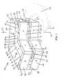
- FIG. 1is a top perspective view of a preferred embodiment of a permanent magnet assembly according to the invention having axial gap flux, an exterior flux return path, and straight-segment configuration features;
- FIG. 2is a bottom perspective view of the permanent magnet assembly of FIG. 1 ;
- FIG. 3is a cross-sectional view of the permanent magnet assembly of FIG. 1 taken along the line 3 — 3 thereof;
- FIG. 4is a perspective view of an embodiment of a permanent magnet assembly according to the invention having axial gap flux, an exterior flux return path, and curved configuration features;
- FIG. 5is a cross-sectional view of the permanent magnet assembly of FIG. 4 taken along the line 5 — 5 thereof;
- FIG. 6is a perspective view of an embodiment of a permanent magnet assembly according to the invention having two air gaps at high magnetic field with axial gap flux, an interior flux return path, and primarily straight configuration features;
- FIG. 7is a cross-sectional view of the permanent magnet assembly of FIG. 6 taken along the line 7 — 7 thereof;
- FIG. 8is a perspective view of an embodiment of a permanent magnet assembly according to the invention having radial gap flux, a lower flux return path, and curved configuration features;
- FIG. 9is a cross-sectional view of the permanent magnet assembly of FIG. 8 taken along the line 9 — 9 thereof;
- FIG. 10is a cross-sectional view of a permanent magnet assembly according to the invention having a simple array construction
- FIG. 11is a cross-sectional view of a permanent magnet assembly according to the invention having a simple array construction with a simple outer sheath;
- FIG. 12is a cross-sectional view of a permanent magnet assembly according to the invention having a simple array construction with a complex outer sheath;
- FIG. 13is a cross-sectional view of a permanent magnet assembly according to the invention having a simple array construction with tapered pole pieces;
- FIG. 14is a cross-sectional view of a permanent magnet assembly according to the invention having a simple array construction with magnetic blocking poles;
- FIG. 15is a top perspective view of another permanent magnet assembly according to the invention having axial gap flux, an interior flux return path, and V-shaped gap regions at each end of the assembly;
- FIG. 16is a cross-sectional view of the permanent magnet assembly of FIG. 15 taken along the line 16 — 16 thereof.
- FIGS. 1 , 2 , 4 , 6 , and 8provide perspective views of three-dimensional permanent magnet assemblies that include permanent magnet portions.
- each permanent magnet portionis formed as a polyhedral solid having multiple faces, as an arc-shaped solid having a rectangular or square cross-section, or as a slight variation of those shapes using a minimal number of straight cuts.
- Each permanent magnet portionis magnetized, with a direction of magnetization (the magnetization vector) that is often either substantially parallel or substantially perpendicular (normal) relative to a particular face of that permanent magnet portion.
- a typical bar magnethaving a North end and a South end has a magnetization vector that is substantially parallel to the four faces along the length of the bar magnet, and substantially normal to the two opposing faces at the ends.
- each exposed face of a permanent magnet portionincludes a mark that indicates the primary direction of the magnetization vector of that permanent magnet portion relative to that face whenever it is practical to do so.
- a face of a permanent magnet portion that lies approximately parallel to the magnetization vector in that permanent magnet portionwill be referred to herein as a “flux parallel” face.
- An arrow on a face of a permanent magnet portionmeans that face is a flux parallel face, and that the magnetization vector in that permanent magnet portion is pointed in the direction of the arrow.
- the point of the arrowmay be considered the North end of the magnetization vector and the tail of the arrow may be considered the South end of the magnetization vector.
- an X on a face of a permanent magnet portionmeans that the magnetization vector in that permanent magnet portion is pointed into that permanent magnet portion.
- a convenient way to remember thisis to think of the X as the feathers on the tail of an arrow going into the face.
- a face of a permanent magnet portion bearing an Xmay be considered the South end of that permanent magnet portion. If the magnetization vector is approximately normal to that face, the face will be referred to herein as a “flux entry” face. If the magnetization vector is at an acute (less than about 90 degree) angle to that face, the face will be referred to herein as a “partial flux entry” face.
- the term “at least a partial flux entry face” hereinincludes both flux entry faces and partial flux entry faces.
- an O with a dot in the center on a face of a permanent magnet portionindicates that the magnetic vector is pointed out of that permanent magnet portion. This can be remembered by thinking of the O with a dot in the center as representing the point of an arrow emerging from the face.
- a face of a permanent magnet portion bearing an O with a dot in the centermay be considered the North end of that permanent magnet portion.
- the magnetization vectoris approximately normal to that face, the face will be referred to herein as a “flux exit” face.
- the magnetization vectoris at an acute (less than about 90 degree) angle to that face, the face will be referred to herein as a “partial flux exit” face.
- the term “at least a partial flux exit face” hereinincludes both flux exit faces and partial flux exit faces.
- the depicted direction of the magnetization vector of any particular permanent magnet portionis the magnetization vector of that permanent magnet portion in isolation.
- the direction of magnetic fluxwill, of course, shift when that permanent magnet portion is coupled with other permanent magnet portions having different magnetization vectors to form a composite permanent magnet assembly.
- FIGS. 3 , 5 , 7 , 9 , and 10 – 14include cross-sections of permanent magnet portions.
- the magnetization vectorsare approximately parallel to the plane of the cross-section, and each cross-section of a permanent magnet portion bears an arrow indicating the direction of the magnetization vector in that portion.
- the point of the arrowmay be considered the North end of the magnetization vector and the tail of the arrow may be considered the South end of the magnetization vector.
- the permanent magnet portions, including blocking magnets, of the various embodiments of a permanent magnet assembly according to the invention disclosed hereincan be formed of any suitable permanent magnet material, for example of the type sold by Sumitomo Special Metals of Japan under the trademark Neomax 50, or a combination of suitable materials.
- the magnetically permeable portionscan be formed of any suitable magnetically permeable material, for example a structural alloy such as low-carbon steel that has the ability to carry flux, or a specifically permeable material intended for use in magnetics such as the material sold by High Temp Metals of California, USA under the trademark Permendur 2V, or a combination of suitable materials.
- a structural alloysuch as low-carbon steel that has the ability to carry flux
- a specifically permeable material intended for use in magneticssuch as the material sold by High Temp Metals of California, USA under the trademark Permendur 2V, or a combination of suitable materials.
- FIG. 1is a top perspective view of a preferred embodiment of a permanent magnet assembly according to the invention, indicated generally at 20 .
- the permanent magnet assembly 20surrounds an air gap at high magnetic field 21 having a rectangular cross section 22 .
- the permanent magnet assembly 20is adapted to rotate about an axis of rotation 23 , whereby the air gap 21 sweeps an annular region 24 having a rectangular cross section 22 .
- a portion of the annular region 24is shown in dotted lines in FIG. 1 .
- the air gap 21 of the permanent magnet assembly 20corresponds to a straight-segment approximation of a portion of the annular region 24 , covering an arc length of approximately 120 degrees.
- the cross-section of the air gap 21is preferably rectangular, this is not necessary, and other shapes may be used.
- the arc lengthmay be greater than or less than 120 degrees.
- the permanent magnet assembly 20is said to have axial gap flux, since the direction of magnetic flux through the air gap 21 is parallel to the axis of rotation 23 .
- the permanent magnet assembly 20is also said to have an external flux return path, since the magnetic flux returns through a path outside the radius of the air gap 21 (from the axis of rotation 23 ) after crossing the air gap 21 .
- the permanent magnet assembly 20may be said to have straight-segment configuration features, since it is formed of blocks having straight sides only with no curved surfaces.
- the permanent magnet assembly 20is preferably made entirely from rectangular blocks of sintered material with no more than one diagonal cut. With such a construction, any pre-assembly grinding operations are performed on flat surfaces, thereby simplifying the manufacturing process.
- the permanent magnet assembly 20includes a first upper radial magnet portion 30 , formed as a six faced polyhedral solid and having a magnetization vector extending substantially in a radial direction (normal to the axis of rotation 23 ).
- the upper exposed face 31 of the upper radial magnet portionis preferably trapezoidal in shape.
- the upper exposed face 31is bounded by a major parallel edge 32 , a minor parallel edge 33 , an outside edge 34 , and an inside edge 35 .
- the upper radial magnet portion 30has a second trapezoidal face (hidden in FIG. 1 ) directly below, opposite, and parallel to the upper exposed face 31 , having approximately the same trapezoidal shape as the upper exposed face 31 .
- the upper exposed face 31 and the parallel second trapezoidal faceare both flux parallel faces.
- the upper radial magnet portion 30has an inside lateral face (hidden in FIG. 1 ), approximately rectangular in shape and extending downward from the inside edge 35 of the upper exposed face 31 to the corresponding edge of the parallel second trapezoidal face. Opposite the inside lateral face, the upper radial magnet portion 30 has an outside lateral face (hidden in FIG. 1 ), approximately rectangular in shape and extending downward from the outside edge 34 of its upper exposed face 31 to the corresponding edge of the parallel second trapezoidal face.
- the upper radial magnet portionhas an inside radial face (hidden in FIG. 1 ), approximately rectangular in shape and extending downward from the minor parallel edge 33 of the upper exposed face 31 to the corresponding edge of the parallel second trapezoidal face.
- the upper radial magnet portion 30has an outside radial face (hidden in FIG. 1 ), approximately rectangular in shape and extending downward from the major parallel edge 32 of its upper exposed face 31 to the corresponding edge of the parallel second trapezoidal face.
- the outside radial faceis a flux entry face
- the inside radial faceis a flux exit face.
- the permanent magnet assembly 20includes a second upper radial magnet portion 36 having an inside edge 37 .
- the upper exposed face of the second upper radial magnet portion 36is a trapezoid, and is shaped as a mirror image (along its inside edge 37 ) of the upper exposed face 31 of the first upper radial magnet portion 30 .
- the second upper radial magnet portion 36has a second trapezoidal face (hidden in FIG. 1 ) directly below, opposite, and parallel to its upper exposed face.
- the second upper radial magnet portion 36has an inside lateral face, an outside lateral face, an inside radial face, and an outside radial face, all of which are hidden in FIG. 1 and shaped generally like the corresponding faces of the upper radial magnet portion 30 .
- the outside radial face of the second upper radial magnet portionis a flux entry face, and its inside radial face is a flux exit face.
- the first upper radial magnet portion 30is preferably, but not necessarily, formed by cutting off a corner of a permanent magnet shaped as a rectangular block, using a single cut along the line that becomes the inside edge 35 of the first upper radial magnet portion 30 .
- the second upper radial magnet portion 36is preferably, but not necessarily, formed by cutting off a corner of a permanent magnet shaped as a rectangular block, using a single cut along the line that becomes the inside edge 37 of the second upper radial magnet portion 36 .
- the permanent magnet assembly 20also includes a first upper axial magnet portion 40 and a second upper axial magnet portion 41 , each formed as a six faced polyhedral solid and having a magnetization vector extending substantially parallel to the axis of rotation 23 .
- the upper exposed face 42 of the second upper axial magnet portion 41is preferably trapezoidal in shape.
- the upper exposed face 42is bounded by a major parallel edge 43 , a minor parallel edge 44 , an outside edge 45 , and an inside edge 46 .
- the upper axial magnet portion 41has a second trapezoidal face (hidden in FIG. 1 ) directly below, opposite, and parallel to the upper exposed face 42 , having approximately the same trapezoidal shape as the upper exposed face 42 .
- the upper exposed face 42is a flux entry face
- the parallel second trapezoidal faceis a flux exit face.
- the upper axial magnet portion 41has an inside lateral face (hidden in FIG. 1 ), approximately rectangular in shape and extending downward from the inside edge 46 of the upper exposed face 42 to the corresponding edge of the parallel second trapezoidal face. Opposite the inside lateral face, the upper axial magnet portion 41 has an outside lateral face (hidden in FIG. 1 ), approximately rectangular in shape and extending downward from the outside edge 45 of its upper exposed face 42 to the corresponding edge of the parallel second trapezoidal face.
- the upper axial magnet portion 41has an inside radial face (hidden in FIG. 1 ), approximately rectangular in shape and extending downward from the minor parallel edge 44 of the upper exposed face 42 to the corresponding edge of the parallel second trapezoidal face. Opposite the inside radial face, the upper axial magnet portion 41 has an outside radial face (hidden in FIG. 1 ), approximately rectangular in shape and extending downward from the major parallel edge 43 of its upper exposed face 42 to the corresponding edge of the parallel second trapezoidal face.
- the first upper axial magnet portion 40has a trapezoidal upper exposed face shaped as a mirror image of the upper exposed face 42 of the second upper axial magnet portion 41 (along its inside edge 46 ). Like the second upper axial magnet portion, the first upper axial magnet portion 40 has a second trapezoidal face (hidden in FIG. 1 ) directly below, opposite, and parallel to its upper exposed face.
- the first upper radial magnet portion 40has an inside lateral face, an outside lateral face, an inside radial face, and an outside radial face, all of which are hidden in FIG. 1 and shaped generally like the corresponding faces of the second upper axial magnet portion 41 .
- the trapezoidal upper exposed face of the first upper axial magnet portion 40is a flux entry face, and its parallel second trapezoidal face is a flux exit face.
- the second upper axial magnet portion 41is preferably, but not necessarily, formed by cutting off a corner of a permanent magnet shaped as a rectangular block, using a single cut along the line that becomes the inside edge 46 of the second upper axial magnet portion 41 .
- the first upper axial magnet portion 40is preferably, but not necessarily, formed by cutting off a corner of a permanent magnet shaped as a rectangular block, using a single cut along the line that becomes the inside lateral face of the first upper axial magnet portion 40 .
- the permanent magnet assembly 20preferably includes a first upper circumferential blocking magnet portion 50 and a second upper circumferential blocking magnet portion 51 , each formed as a six faced rectangular block and having a magnetization vector extending substantially circumferentially (normal to a radius extending from the axis of rotation 23 ).
- the exposed outside lateral faces of the first upper circumferential blocking magnet portion 50 and second upper circumferential blocking magnet portion 51are flux entry faces.
- the first upper circumferential blocking magnet portion 50 and the second upper circumferential blocking magnet portion 51each have an inside lateral face (hidden in FIG. 1 ), approximately rectangular in shape and extending downward from the inside edges 52 of those upper circumferential blocking magnet portions.
- the hidden inside lateral faces of the first upper circumferential blocking magnet portion 50 and second upper circumferential blocking magnet portion 51are flux exit faces.
- the first upper circumferential blocking magnet portion 50 and the second upper circumferential blocking magnet portion 51are preferably, but not necessarily, formed of a permanent magnet shaped as a rectangular block.
- the permanent magnet assembly 20preferably includes a first upper radial blocking magnet portion 54 and a second upper radial blocking magnet portion 55 , each formed as a six faced rectangular block and having a magnetization vector extending substantially radially (normal to the axis of rotation 23 ).
- the exposed outside radial faces of the first upper radial blocking magnet portion 54 and second upper radial blocking magnet portion 55are flux entry faces.
- the first upper radial blocking magnet portion 54 and the second upper radial blocking magnet portion 55each have an inside radial face (hidden in FIG. 1 ), approximately rectangular in shape and extending downward from the inside edges 56 of those upper radial blocking magnet portions.
- the hidden inside radial faces of the first upper radial blocking magnet portion 54 and second upper radial blocking magnet portion 55are flux exit faces.
- the first upper radial blocking magnet portion 54 and the second upper radial blocking magnet portion 55are preferably, but not necessarily, formed by cutting off a corner of a permanent magnet shaped as a rectangular block, using a single straight cut to form the faces where the first upper radial blocking magnet portion 54 and the second upper radial blocking magnet portion 55 meet.
- the permanent magnet assembly 20includes a first central axial magnet portion 58 and a second central axial magnet portion 59 , each formed as a six faced polyhedral solid with a magnetization vector extending substantially in an axial direction (parallel to the axis of rotation 23 ).
- the upper and lower faces (hidden in FIG. 1 ) of the central axial magnet portionsare preferably trapezoidal in shape.
- the upper trapezoidal facesare flux exit faces and the lower trapezoidal face are flux entry faces.
- the first central axial magnet portion 58has an inside lateral face that meets the inside lateral face of the second central axial magnet portion 59 , both inside lateral faces being approximately rectangular in shape. Opposite the inside lateral face, the central axial magnet portions each have an exposed outside lateral face, also approximately rectangular in shape. The central axial magnet portions each have an inside radial face (partially visible in FIG. 1 ) that is approximately rectangular in shape. Opposite the inside radial face, each of the central axial magnets has an outside radial face (hidden in FIG. 1 ), also approximately rectangular in shape.
- the first central axial magnet portion 58 and second central axial magnet portion 59are each preferably, but not necessarily, formed by cutting off a corner of a permanent magnet shaped as a rectangular block, using a single cut along the line that becomes the inside lateral face of each central axial magnet portion.
- the first central axial magnet portion 58 and second central axial magnet portion 59provide a return path for the lines of magnetic flux through the air gap 21 .
- the first central axial magnet portion 58 and second central axial magnet portion 59preferably have the same vertical dimension as the air gap 21 for convenient fabrication and assembly, and are preferably shaped and exteriorly positioned at a sufficient distance from the air gap 21 to prevent shunting of the gap flux into the flux return path.
- FIG. 2is a bottom perspective view of the permanent magnet assembly of FIG. 1 .
- the permanent magnet assembly 20includes a first lower radial magnet portion 60 and a second lower radial magnet portion 61 .
- These lower radial magnet portionsare generally shaped like the upper radial magnet portions 30 and 36 , and are also preferably formed by cutting off a corner of a rectangular block permanent magnet using a single cut.
- the magnetization vectors in the lower radial magnet portionspoint in a direction opposite to the magnetization vectors in the corresponding upper radial magnet portions.
- the permanent magnet assembly 20includes a first lower axial magnet portion 63 and a second lower axial magnet portion 64 .
- These lower axial magnet portionsare generally shaped like the upper axial magnet portions 40 and 41 , and are also preferably formed by cutting off a corner of a rectangular block permanent magnet using a single cut.
- the magnetization vectors in the lower axial magnet portionspoint in the same direction as the magnetization vectors in the corresponding upper axial magnet portions.
- the permanent magnet assembly 20also preferably includes a first lower circumferential blocking magnet portion 66 and a second lower circumferential blocking magnet portion 67 .
- These lower circumferential blocking magnet portionsare generally shaped like the upper circumferential blocking magnet portions 50 and 51 , and are also preferably formed of a single rectangular block permanent magnet.
- the magnetization vectors in the lower circumferential blocking magnet portionspoint in a direction opposite to the magnetization vectors in the corresponding upper circumferential blocking magnet portions.
- the permanent magnet assembly 20also preferably includes a first lower radial blocking magnet portion 68 and a second lower radial blocking magnet portion 69 .
- These lower radial blocking magnet portionsare generally shaped like the upper radial blocking magnet portions 54 and 55 , and are also preferably formed of a single rectangular block permanent magnet.
- the magnetization vectors in the lower circumferential blocking magnet portionspoint in a direction opposite to the magnetization vectors in the corresponding upper circumferential blocking magnet portions.
- FIG. 3is a cross-sectional view of the permanent magnet assembly 20 of FIG. 1 taken along the line 3 — 3 thereof.
- the cross-sectional view of FIG. 3shows how a magnetic flux loop is formed by the lower axial magnet portion 63 , the lower radial magnet portion 60 , the central axial magnet portion 58 , the upper radial magnet portion 30 , the upper axial magnet portion 40 , and the air gap at high magnetic field 21 .
- the permanent magnet assembly 20preferably includes the circumferential blocking magnet portions 50 , 51 , 66 , and 67 and the radial blocking magnet portions 54 , 55 , 68 , and 69 to control the rate of field decay outside of the air gap at high magnetic field 21 .
- Increasing the magnetic flux from these blocking magnet portionsfor example by increasing the thickness of the blocking magnet portions or by forming the blocking magnet portions from stronger permanent magnet material, can provide a sharper transition from the high field strength in the air gap at high magnetic field 21 to the low field region outside of the permanent magnet assembly 20 .
- FIG. 4is a perspective view of another embodiment of a permanent magnet assembly 70 according to the invention.
- the permanent magnet assembly 70surrounds an air gap at high magnetic field 21 having a rectangular cross section.
- the cross-section of the air gap 21is preferably rectangular, this is not necessary, and other shapes may be used.
- the permanent magnet assembly 70 of FIG. 4is adapted to rotate about an axis of rotation 23 , whereby the air gap 21 sweeps an annular region having a rectangular cross section (not shown in FIG. 4 ).
- the air gap 21 of the permanent magnet assembly 70covers an arc length of approximately 120 degrees, although this is not required and the arc length may be greater than or less than 120 degrees.
- the permanent magnet assembly 70is said to have axial gap flux, since the direction of magnetic flux through the air gap 21 is substantially parallel to the axis of rotation 23 .
- the permanent magnet assembly 70is also said to have an external flux return path, since the magnetic flux returns through a path outside the radius of the air gap 21 (from the axis of rotation 23 ) after crossing the air gap 21 .
- the permanent magnet assembly 20may be said to have curved configuration features, since it is formed of blocks having curved surfaces.
- the permanent magnet assembly 70includes an upper axial magnet portion 71 formed as an arc-shaped solid having six faces, a rectangular or square cross-section, and a magnetization vector extending substantially parallel to the axis of rotation 23 .
- the upper axial magnet portion 71can be formed of two pieces, as shown in FIG. 4 , or it can be formed of a single piece or a greater number of pieces.
- the arc-shaped upper face of the upper axial magnet portion 71is a flux entry face, and the corresponding arc-shaped lower face of the upper axial magnet portion 71 is a flux exit face.
- the inside radial face of the upper axial magnet portion 71is the face nearest to the axis of rotation and normal to a radius extending from the axis of rotation.
- the outside radial face of the upper axial magnet portion 71is the face farthest from the axis of rotation and normal to a radius extending from the axis of rotation.
- the inside and outside radial facesare both flux parallel faces.
- the first and second circumferential faces of the upper axial magnet portion 71are the faces forming the ends of the upper axial magnet portion 71 .
- the first and second circumferential faces of the upper axial magnet portion 71are both flux parallel faces.
- the permanent magnet assembly 70includes an upper radial magnet portion 72 formed as an arc-shaped solid having six faces, a rectangular or square cross-section, and a magnetization vector extending substantially in a radial direction (normal to the axis of rotation 23 ).
- the upper radial magnet portion 72can be formed of two pieces, as shown in FIG. 4 , or it can be formed of a single piece or a greater number of pieces.
- the arc-shaped upper and lower faces of the upper radial magnet portion 72are both flux parallel faces.
- the inside radial face of the upper radial magnet portion 72is the face nearest to the axis of rotation and normal to a radius extending from the axis of rotation.
- the outside radial face of the upper axial magnet portion 72is the face farthest from the axis of rotation and normal to a radius extending from the axis of rotation.
- the inside radial faceis a flux exit face, and the outside radial face is a flux entry face.
- the first and second circumferential faces of the upper radial magnet portion 72are the faces forming the ends of the upper radial magnet portion 72 .
- the first and second circumferential faces of the upper radial magnet portion 72are both flux parallel faces.
- the permanent magnet assembly 70includes a central axial magnet portion 73 formed as an arc-shaped solid having six faces, a rectangular or square cross-section, and a magnetization vector extending substantially in an axial direction (parallel to the axis of rotation 23 ).
- the central axial magnet portion 73can be formed of multiple pieces, or it can be formed of a single piece.
- the arc-shaped upper face of the central axial magnet portion 73is a flux exit face, and the arc-shaped lower face of the central axial magnet portion 73 is a flux entry face.
- the inside radial face of the central axial magnet portion 73is the face nearest to the axis of rotation and normal to a radius extending from the axis of rotation.
- the upper and lower corners of the inside radial face of the central axial magnet portion 73preferably include an upper chamfer 74 and a lower chamfer 75 , as best shown in FIG. 5 , although this is not required.
- the outside radial face of the central axial magnet portion 73is the face farthest from the axis of rotation and normal to a radius extending from the axis of rotation.
- the inside radial face and the outside radial face of the central axial magnet portion 73are both flux parallel faces.
- the first and second circumferential faces of the central axial magnet portion 73are the faces forming the ends of the central axial magnet portion 73 . As shown in FIG. 4 , The first and second circumferential faces of the central axial magnet portion 73 are both flux parallel faces.
- the central axial magnet portion 73provides a return path for the lines of magnetic flux through the air gap 21 .
- the central axial magnet portion 73is preferably shaped and exteriorly positioned at a sufficient distance from the air gap 21 to prevent shunting of the gap flux into the flux return path.
- the permanent magnet assembly 70includes a lower radial magnet portion 76 shaped like the upper radial magnet portion 72 , with a magnetization vector also extending substantially in a radial direction (normal to the axis of rotation 23 ).
- the magnetization vector in the lower radial magnet portion 76points in a direction opposite to the magnetization vector in the corresponding upper radial magnet portion 72 .
- the permanent magnet assembly 70includes a lower axial magnet portion 77 shaped like the upper axial magnet portion 71 , with a magnetization vector also extending substantially in an axial direction (parallel to the axis of rotation 23 ).
- the magnetization vector in the lower axial magnet portion 77points in the same direction as the magnetization vector in the corresponding upper axial magnet portion 71 .
- the permanent magnet assembly 70preferably includes an upper sheath 78 formed of magnetically permeable material.
- the upper sheath 78preferably has a trapezoidal cross-section, with a inner chamfer 79 , an outer chamfer 80 , and upper and lower faces, although this is not required and other shapes may be used.
- the lower face of the upper sheath 78preferably covers the junction between the upper axial magnet portion 71 and the upper radial magnet portion 72 , and at least a portion of the upper faces of the upper axial magnet portion 71 and the upper radial magnet portion 72 .
- the permanent magnet assembly 70preferably includes an exterior sheath 81 formed of magnetically permeable material.
- the exterior sheath 81preferably has a trapezoidal cross-section, with an upper chamfer 82 , a lower chamfer 83 , and inner and outer faces, although this is not required and other shapes may be used.
- the inner face of the exterior sheath 81preferably covers at least a portion of the outside radial faces of each of the upper radial magnet portion 72 , the central axial magnet portion 73 , and the lower radial magnet portion 76 , and the junctions therebetween.
- the permanent magnet assembly 70preferably includes an lower sheath 84 formed of magnetically permeable material.
- the lower sheath 84preferably has a trapezoidal cross-section, with an inner chamfer 85 , an outer chamfer 86 , and upper and lower faces, although this is not required and other shapes may be used.
- the upper face of the lower sheath 84preferably covers the junction between the lower axial magnet portion 77 and the lower radial magnet portion 76 , and at least a portion of the lower faces of the lower axial magnet portion 77 and the lower radial magnet portion 76 .
- the permanent magnet assembly 70preferably includes an upper pole piece 87 and a lower pole piece 88 surrounding the air gap at high magnetic field 21 .
- the upper pole piece 87 and lower pole piece 88are each formed as an arc-shaped solid, and preferably include at least one chamfer 89 .
- the upper face of the upper pole piece 87is preferably coupled to the lower face of the upper axial magnet portion 71
- the chamfer 89 of the upper pole piece 87is preferably coupled to the upper chamfer 74 of the central axial magnet portion 73 .
- the lower face of the lower pole piece 88is preferably coupled to the upper face of the lower axial magnet portion 77
- the chamfer 89 of the lower pole piece 88is preferably coupled to the lower chamfer 75 of the central axial magnet portion 73 .
- FIG. 5is a cross-sectional view of the permanent magnet assembly 70 of FIG. 4 taken along the line 5 — 5 thereof.
- the cross-sectional view of FIG. 5shows how a magnetic flux loop is formed by the lower axial magnet portion 77 , the lower radial magnet portion 76 , the central axial magnet portion 73 , the upper radial magnet portion 72 , the upper axial magnet portion 71 , and the air gap at high magnetic field 21 .
- the permanent magnet assembly 70preferably includes an upper pole piece 87 and a lower pole piece 88 surrounding the air gap at high magnetic field 21 to guide and concentrate the magnetic flux through the air gap at high magnetic field 21 .
- FIG. 6is a perspective view of another embodiment of a permanent magnet assembly 90 according to the invention.
- the permanent magnet assembly 90has two ends, each end surrounding an air gap at high magnetic field 21 having a rectangular cross section, where both air gaps experience the same direction of magnetic flux.
- the cross-sections of the air gaps 21are preferably rectangular, this is not necessary, and other shapes may be used.
- the geometry of the pieces in this permanent magnet assembly 90allows the majority of any grinding operations needed during the manufacturing stage to be performed on flat surfaces.
- the permanent magnet assembly 90 of FIG. 6is adapted to rotate about an axis of rotation 23 , whereby the air gaps 21 sweep an annular region having a rectangular cross section (not shown in FIG. 6 ).
- the air gaps 21 of the permanent magnet assembly 70each cover an arc length of approximately 60 degrees, for a total arc coverage of 120 degrees, although this is not required and the total arc length may be greater than or less than 120 degrees.
- the permanent magnet assembly 90may be especially useful in rotating magnet applications which benefit from minimization of the rotational moment of inertia.
- the permanent magnet assembly 90is said to have axial gap flux, since the direction of magnetic flux through the air gaps 21 is substantially parallel to the axis of rotation 23 .
- the permanent magnet assembly 90is also said to have an internal flux return path, since the magnetic flux returns through a central path surrounding the axis of rotation 23 after crossing the air gap 21 .
- the permanent magnet assembly 20may be said to have straight configuration features, since it is comprised entirely of rectangular blocks with the exception of a disk magnet at the center with two flattened edges (the central axial magnet portion 91 ).
- the permanent magnet assembly 90includes a central axial magnet portion 91 formed of a disk magnet having flattened upper and lower faces, with a magnetization vector parallel to the axis of rotation 23 .
- the central axial magnet portionpreferably includes flattened lateral edges on each side, although this is not required.
- the upper face of the central axial magnetis a flux exit face
- the lower face of the central axial magnetis a flux entry face.
- the central axial magnet portion 91provides a return path for the lines of magnetic flux through the air gap 21 .
- the central axial magnet portion 91is preferably shaped and interiorly positioned at a sufficient distance from the air gap 21 to prevent shunting of the gap flux into the flux return path.
- the upper portion of the permanent magnet assembly 90preferably includes a central permeable slab 92 , for example a block of low-carbon steel, surrounding the axis of rotation 23 , although this is not required.
- the central permeable slab 92serves to neutralize repulsive magnetic forces in the center of the assembly resulting from the adjacent permanent magnet portions.
- the upper portion of the permanent magnet assembly 90includes a first upper radial magnet portion 93 and a second upper radial magnet portion 98 adjacent to the central permeable slab 92 , each upper radial magnet portion preferably formed of a rectangular block permanent magnet having a radial magnetization vector (normal to the axis of rotation 23 ).
- Each of the upper radial magnet portions 93 and 98has an exposed upper face, preferably rectangular or square in shape, and having an inside radial edge 94 , an outside radial edge 95 , a first lateral edge 96 , and a second lateral edge 97 .
- Each upper radial magnet portionhas a hidden lower face (hidden in FIG. 6 ) directly below, opposite, and parallel to the exposed upper face, having approximately the same square or rectangular shape as the exposed upper face.
- the upper exposed faces and the parallel hidden lower faces of the upper magnet portionare all flux parallel faces.
- Each upper radial magnet portion 93 and 98has an inside radial face (hidden in FIG. 6 ), approximately rectangular in shape and extending downward from the inside radial edge 94 of the upper exposed face to the corresponding edge of the parallel hidden lower face. Opposite the inside radial face, each upper radial magnet portion 93 and 98 has an outside radial face (hidden in FIG. 6 ), approximately rectangular in shape and extending downward from the outside radial edge 95 of the upper exposed face to the corresponding edge of the parallel hidden lower face. As perhaps best shown in FIG. 7 , the inside radial faces of the upper radial magnet portions 93 and 98 are flux entry faces, and the outside radial faces of the upper radial magnet portions 93 and 98 are flux exit faces.
- Each upper radial magnet portion 93 and 98has a first lateral face (hidden in FIG. 6 ), approximately rectangular in shape and extending downward from the first lateral edge 96 of the upper exposed face to the corresponding edge of the parallel hidden lower face.
- Each upper radial magnet portionalso has a second lateral face (hidden in FIG. 6 ), approximately rectangular in shape and extending downward from the second lateral edge 97 of the upper exposed face to the corresponding edge of the parallel hidden lower face.
- the first and second lateral faces of the upper radial magnet portions 93 and 98are all flux parallel faces.
- the upper portion of the permanent magnet assembly 90includes a first upper axial magnet portion 99 adjacent to the first upper radial magnet portion 93 , and a second upper axial magnet portion 100 adjacent to the second upper radial magnet portion 98 , each upper axial magnet portion preferably formed of a rectangular block permanent magnet having a magnetization vector parallel to the axis of rotation 23 .
- Each of the upper axial magnet portions 99 and 100has an exposed upper face, preferably rectangular or square in shape.
- Each upper axial magnet portionhas a hidden lower face (hidden in FIG. 6 ) directly below, opposite, and parallel to the exposed upper face, having approximately the same square or rectangular shape as the exposed upper face.
- the upper exposed faces of the upper axial magnet portions 99 and 100are flux entry faces, and the hidden lower faces of the upper axial magnet portions 99 and 100 are flux exit faces.
- the upper portion of the permanent magnet assembly 90preferably includes a first upper radial blocking magnet portion 101 adjacent to the first upper axial magnet portion 99 , and a second upper radial blocking magnet portion 102 adjacent to the second upper axial magnet portion 100 , each upper radial blocking magnet portion preferably formed of a rectangular block permanent magnet having a radial magnetization vector (normal to the axis of rotation 23 ).
- Each of the upper radial blocking magnet portions 101 and 102has an inside radial face (hidden in FIG. 6 ), preferably rectangular or square in shape and coupled to an adjacent upper axial magnet portion.
- Each upper radial blocking magnet portionhas an exposed outside radial face opposite and parallel to the hidden inside radial face, having approximately the same square or rectangular shape as the hidden inside face.
- the hidden inside radial faces of the upper radial blocking magnet portions 101 and 102are flux exit faces, and the exposed outside radial faces of the upper radial blocking magnet portions 101 and 102 are flux entry faces.
- the lower portion of the permanent magnet assembly 90is similar to the upper portion of the permanent magnet assembly 90 , with appropriate reversals of the magnetization vectors in the magnet portions.
- the lower portion of the permanent magnet assembly 90includes a central permeable slab 92 surrounding the axis of rotation 23 .
- the lower portion of the permanent magnet assembly 90includes a first lower radial magnet portion 103 and a second lower radial magnet portion 104 on the sides of the central permeable slab 92 .
- the lower radial magnet portions 103 and 104are located directly below the corresponding first upper radial magnet portion 93 and second upper radial magnet portion 98 .
- the magnetization vectors in the lower radial magnet portions 103 and 104point in directions opposite to the magnetization vectors in the corresponding upper radial magnet portions 93 and 98 .
- the inside radial faces of the lower radial magnet portions 103 and 104are flux exit faces and the outside radial faces are flux entry faces.
- the lower portion of the permanent magnet assembly 90includes a first lower axial magnet portion 105 adjacent to the first lower radial magnet portion 103 , and a second lower axial magnet portion 106 adjacent to the second lower radial magnet portion 104 .
- the lower axial magnet portions 105 and 106are directly below the corresponding upper axial magnet portions of the upper portion of the permanent magnet assembly 90 , having approximately the same square or rectangular shape, and preferably formed of a rectangular block permanent magnet.
- the lower axial magnet portions 105 and 106each have a magnetization vector parallel to the axis of rotation 23 and pointing in the same direction as the magnetization vectors in the corresponding upper axial magnet portions 99 and 100 .
- the upper face of each of the lower axial magnet portions 105 and 106is a flux entry face
- the lower face of each of the lower axial magnet portions 105 and 106is a flux exit face.
- the lower portion of the permanent magnet assembly 90preferably includes a first lower radial blocking magnet portion 107 adjacent to the first lower axial magnet portion 105 .
- the lower portion of the permanent magnet assembly 90preferably includes a second lower radial blocking magnet portion 108 adjacent to the second lower axial magnet portion 106 .
- each lower radial blocking magnet portionis preferably formed of a rectangular block permanent magnet having a radial magnetization vector (normal to the axis of rotation 23 ).
- the inside radial faces of the lower radial blocking magnet portions 107 and 108are flux entry faces, and the outside radial faces of the lower radial blocking magnet portions 107 and 108 are flux exit faces.
- the permanent magnet assembly 90preferably includes one or more lateral blocking magnet portions 109 , each formed of a rectangular block permanent magnet. As best shown in FIG. 6 , the lateral blocking magnet portions 109 preferably cover the lateral faces of the upper and lower radial magnet portions and central permeable slabs, and the junctions therebetween.
- the magnetization vectors of the lateral blocking magnet portions 109are radial (normal to the axis of rotation 23 ) at the center of the lateral blocking magnet portions 109 .
- the hidden inside faces of the upper blocking magnet portionsare flux exit faces, and the exposed outside faces of the upper blocking magnet portions are flux entry faces.
- the hidden inside faces of the lower blocking magnet portionsare flux entry faces, and the exposed outside faces of the upper blocking magnet portions are flux exit faces.
- FIG. 7is a cross-sectional view of the permanent magnet assembly of FIG. 6 taken along the line 7 — 7 thereof.
- the cross-sectional view of FIG. 7shows how a first magnetic flux loop is formed by the lower axial magnet portion 105 , the lower radial magnet portion 103 , the central axial magnet portion 91 , the upper radial magnet portion 93 , the upper axial magnet portion 99 , and a first air gap at high magnetic field 21 .
- a second magnetic flux loopis formed by the lower axial magnet portion 106 , the lower radial magnet portion 104 , the central axial magnet portion 91 , the upper radial magnet portion 98 , the upper axial magnet portion 100 , and a second air gap at high magnetic field 21 .
- the lateral blocking magnet portions 109prevent stray field from leaking into the nearby low field regions on each side of the permanent magnet assembly 90 (offset 90 degrees from the air gaps at high magnetic field 21 ). This also helps to ensure a sharp field decay away from the air gaps at high magnetic field 21 by forcing any stray flux outside the diameter of the annular region swept by rotation of the permanent magnet assembly 109 .
- FIG. 8is a perspective view of another embodiment of a permanent magnet assembly 110 according to the invention.
- the permanent magnet assembly 110surrounds an air gap at high magnetic field 21 having a rectangular cross section.
- the cross-section of the air gap 21is preferably rectangular, this is not necessary, and other shapes may be used.
- the permanent magnet assembly 110 of FIG. 8is adapted to rotate about an axis of rotation 23 , whereby the air gap 21 sweeps an annular region having a rectangular cross section (not shown in FIG. 8 ).
- the air gap 21 of the permanent magnet assembly 110covers an arc length of approximately 120 degrees, although this is not required and the arc length may be greater than or less than 120 degrees.
- the permanent magnet assembly 110is said to have radial gap flux, since the direction of magnetic flux through the air gap 21 is substantially normal (perpendicular) to the axis of rotation 23 .
- the permanent magnet assembly 110is also said to have a lower flux return path, since the magnetic flux returns through a path below the air gap 21 after crossing the air gap 21 .
- the permanent magnet assembly 110may be said to have curved configuration features, since it is formed of blocks having curved surfaces.
- the permanent magnet assembly 110includes an exterior radial magnet portion 111 formed as an arc-shaped solid having six faces, a rectangular or square cross-section, and a radial magnetization vector extending substantially normal to the axis of rotation 23 .
- the exterior radial magnet portion 111can be formed of a single piece or multiple pieces.
- the inside radial face (hidden in FIG. 8 ) of the exterior radial magnet portion 111is the face nearest to the axis of rotation and normal to a radius extending from the axis of rotation.
- the outside radial face (also hidden in FIG. 8 ) of the exterior radial magnet portion 111is the face farthest from the axis of rotation and normal to a radius extending from the axis of rotation.
- the inside radial face of the exterior radial magnet portion 111is a flux exit face, and the outside radial face of the exterior radial magnet portion 111 is a flux entry face.
- the upper face of the exterior radial magnet portion 111 (exposed in FIG. 8 ) and the lower face of the exterior radial magnet portion 111 (hidden in FIG. 8 )are both flux parallel faces.
- the first and second circumferential faces of the exterior radial magnet portion 111are the faces forming the ends of the exterior radial magnet portion 111 .
- the first and second circumferential faces of the exterior radial magnet portion 111are both flux parallel faces.
- the permanent magnet assembly 110includes an exterior axial magnet portion 112 formed as an arc-shaped solid having six faces, a rectangular or square cross-section, and an axial magnetization vector extending substantially parallel to the axis of rotation 23 .
- the exterior axial magnet portion 112can be formed of a single piece or multiple pieces.
- the inside radial face (hidden in FIG. 8 ) of the exterior axial magnet portion 112is the face nearest to the axis of rotation and normal to a radius extending from the axis of rotation.
- the outside radial face (partially exposed in FIG. 8 ) of the exterior axial magnet portion 112is the face farthest from the axis of rotation and normal to a radius extending from the axis of rotation.
- the inside radial face and outside radial face of the exterior axial magnet portion 112are both flux parallel faces.
- the upper face of the exterior axial magnet portion 112(hidden in FIG. 8 ) is a flux exit face, and the lower face of the exterior axial magnet portion 112 (hidden in FIG. 8 ) is a flux entry face.
- the first and second circumferential faces of the exterior axial magnet portion 112are the faces forming the ends of the exterior axial magnet portion 112 .
- the first and second circumferential faces of the exterior axial magnet portion 112are both flux parallel faces.
- the permanent magnet assembly 110includes a central radial magnet portion 113 formed as an arc-shaped solid having six faces, a rectangular or square cross-section, and a magnetization vector extending substantially in a radial direction (normal to the axis of rotation 23 ).
- the central radial magnet portion 113can be formed of multiple pieces, or it can be formed of a single piece.
- the inside radial face of the central radial magnet portion 113is the face nearest to the axis of rotation and normal to a radius extending from the axis of rotation.
- the outside radial face of the central radial magnet portion 113is the face farthest from the axis of rotation and normal to a radius extending from the axis of rotation.
- the inside radial face of the central radial magnet portion 113is a flux entry face
- the outside radial face of the central radial magnet portion 113is a flux exit face.
- the upper face and the lower face of the central radial magnet portion 113are both flux parallel faces.
- the outside corner of the upper face of the central radial magnet portion 113preferably includes an exterior chamfer 114
- the inside cornerpreferably includes an interior chamfer 115 , although this is not required.
- the first and second circumferential faces of the central radial magnet portion 113are the faces forming the ends of the central radial magnet portion 113 . As shown in FIG. 8 , the first and second circumferential faces of the central radial magnet portion 113 are both flux parallel faces.
- the central radial magnet portion 113provides a return path for the lines of magnetic flux through the air gap 21 .
- the central radial magnet portion 113is preferably shaped and positioned at a sufficient distance from the air gap 21 to prevent shunting of the gap flux into the flux return path.
- the permanent magnet assembly 110includes an interior axial magnet portion 116 formed as an arc-shaped solid having six faces, a rectangular or square cross-section, and an axial magnetization vector extending substantially parallel to the axis of rotation 23 .
- the interior axial magnet portion 116can be formed of a single piece or multiple pieces.
- the inside radial face (partially exposed in FIG. 8 ) of the interior axial magnet portion 116is the face nearest to the axis of rotation and normal to a radius extending from the axis of rotation.
- the outside radial face (hidden in FIG. 8 ) of the interior axial magnet portion 116is the face farthest from the axis of rotation and normal to a radius extending from the axis of rotation.
- the inside radial face and outside radial face of the interior axial magnet portion 116are both flux parallel faces.
- the upper face of the interior axial magnet portion 116(hidden in FIG. 8 ) is a flux entry face, and the lower face of the interior axial magnet portion 116 (hidden in FIG. 8 ) is a flux exit face.
- the first and second circumferential faces of the interior axial magnet portion 116are the faces forming the ends of the interior axial magnet portion 116 .
- the first and second circumferential faces of the interior axial magnet portion 116are both flux parallel faces.
- the permanent magnet assembly 110includes an interior radial magnet portion 117 formed as an arc-shaped solid having six faces, a rectangular or square cross-section, and a radial magnetization vector extending substantially normal to the axis of rotation 23 .
- the interior radial magnet portion 117can be formed of a single piece or multiple pieces.
- the inside radial face (hidden in FIG. 8 ) of the interior radial magnet portion 117is the face nearest to the axis of rotation and normal to a radius extending from the axis of rotation.
- the outside radial face (also hidden in FIG. 8 ) of the interior radial magnet portion 117is the face farthest from the axis of rotation and normal to a radius extending from the axis of rotation.
- the inside radial face of the interior radial magnet portion 117is a flux exit face, and the outside radial face of the interior radial magnet portion 117 is a flux entry face.
- the first and second circumferential faces of the interior radial magnet portion 117are the faces forming the ends of the interior radial magnet portion 117 .
- the first and second circumferential faces of the interior radial magnet portion 117are both flux parallel faces.
- the permanent magnet assembly 110preferably includes an exterior pole piece 118 and an interior pole piece 119 surrounding the air gap at high magnetic field 21 .
- the exterior pole piece 118 and interior pole piece 119are each formed as an arc-shaped solid, and preferably include at least one chamfer 120 , although this is not required.
- the exterior radial face of the exterior pole piece 118is preferably coupled to the interior radial face of the exterior radial magnet portion 111 .
- the interior radial face of the exterior pole piece 118preferably faces the air gap at high magnetic field 21 .
- the chamfer 120 of the exterior pole piece 118is preferably coupled to the exterior chamfer 114 of the central radial magnet portion 113 .
- the interior radial face of the interior pole piece 119is preferably coupled to the exterior radial face of the interior radial magnet portion 117 .
- the exterior radial face of the interior pole piece 119preferably faces the air gap at high magnetic field 21 .
- the chamfer 120 of the interior pole piece 119is preferably coupled to the interior chamfer 115 of the central radial magnet portion 113 .
- the permanent magnet assembly 110preferably includes an exterior sheath 121 formed of magnetically permeable material.
- the exterior sheath 121preferably has a trapezoidal cross-section, with upper and lower chamfers 124 , although this is not required and other shapes may be used.
- the exterior sheath 121preferably covers the junction between the exterior radial magnet portion 111 and the exterior axial magnet portion 112 , and at least a portion of the exposed faces of the exterior radial magnet portion 111 and the exterior axial magnet portion 112 .
- the permanent magnet assembly 110also preferably includes an interior sheath 122 formed of magnetically permeable material.
- the interior sheath 122preferably has a trapezoidal cross-section, with upper and lower chamfers 124 , although this is not required and other shapes may be used.
- the interior sheath 122preferably covers the junction between the interior axial magnet portion 116 and the interior radial magnet portion 117 , and at least a portion of the exposed faces of interior axial magnet portion 116 and the interior radial magnet portion 117 .
- the permanent magnet assembly 70preferably includes a lower sheath 123 formed of magnetically permeable material.
- the lower sheath 123preferably has a trapezoidal cross-section, with inside and outside chamfers 124 , although this is not required and other shapes may be used.
- the lower sheath 123preferably covers at least a portion of the exposed faces of each of the exterior axial magnet portion 112 , the central radial magnet portion 113 , and the interior axial magnet portion 116 , and the junctions therebetween.
- FIG. 9is a cross-sectional view of the permanent magnet assembly 110 of FIG. 8 taken along the line 9 - 9 thereof.
- the cross-sectional view of FIG. 9shows how a magnetic flux loop is formed by the interior radial magnet portion 117 , the interior axial magnet portion 116 , the central radial magnet portion 113 , the exterior axial magnet portion 112 , the exterior radial magnet portion 111 , and the air gap at high magnetic field 21 .
- the permanent magnet assembly 110preferably includes the exterior pole piece 118 and interior pole piece 119 surrounding the air gap at high magnetic field 21 to guide and concentrate the magnetic flux through the air gap at high magnetic field 21 .
- the permanent magnet assembly 110preferably includes the exterior sheath 121 , interior sheath 122 , and lower sheath 123 to reduce flux leakage from the assembly.
- the interior axial magnet 116 and interior radial magnet 117 on the near side of the air gap 21 from the axis of rotation 23preferably have a greater cross-sectional area than the exterior axial magnet 112 and exterior radial magnet 111 on the far side of the air gap 21 to help equalize their relative volumes and flux capacity, and thereby prevent over-saturation and flux leakage on the inner radius side.
- the interior pole piece 119preferably has a greater cross-sectional area than the exterior pole piece 118 on the far side of the air gap 21 to help equalize their relative volumes and flux capacity.
- FIG. 10is a cross-sectional view of a permanent magnet assembly according to the invention 130 having a simple array construction.
- the cross-sectional view of FIG. 10shows how a magnetic flux loop is formed by the lower gap field parallel magnet 135 , the lower gap field normal magnet 134 , the central gap field parallel magnet 133 , the upper gap field normal magnet 132 , the upper gap field parallel magnet 131 , and the air gap at high magnetic field 21 .
- FIG. 11is a cross-sectional view of a permanent magnet assembly 140 according to the invention having a simple array construction with a simple flux containment jacket.
- the cross-sectional view of FIG. 11shows how a magnetic flux loop is formed by the lower gap field parallel magnet 135 , the lower gap field normal magnet 134 , the central gap field parallel magnet 133 , the upper gap field normal magnet 132 , the upper gap field parallel magnet 131 , and the air gap at high magnetic field 21 .
- the permanent magnet assembly 140includes a simple flux containment jacket 141 used to minimize stray flux.
- the simple flux containment jacket 141is a magnetically permeable, stray flux containment jacket, made of a magnetically permeable material such as low-carbon steel, Vanadium Cobalt Iron alloy, or some other highly permeable alloy.
- FIG. 12is a cross-sectional view of a permanent magnet assembly according to the invention 145 having a simple array construction with multiple flux containment sheaths.
- the cross-sectional view of FIG. 12shows how a magnetic flux loop is formed by the lower gap field parallel magnet 135 , the lower gap field normal magnet 134 , the central gap field parallel magnet 133 , the upper gap field normal magnet 132 , the upper gap field parallel magnet 131 , and the air gap at high magnetic field 21 .
- the permanent magnet assembly 145includes multiple flux containment sheaths used to minimize stray flux, including an upper containment sheath 146 , a central containment sheath 147 , and a lower containment sheath 148 .
- Each flux containment sheathmay include one or more chamfers 149 .
- the use of multiple flux containment sheaths shown in FIG. 12is better suited to redirect stray flux into the magnetic circuit; however, it also increases the difficulty of manufacturing and assembly.
- FIG. 13is a cross-sectional view of a permanent magnet assembly according to the invention 150 having a simple array construction with tapered pole pieces.
- the cross-sectional view of FIG. 13shows how a magnetic flux loop is formed by the lower gap field parallel magnet 135 , the lower gap field normal magnet 134 , the central gap field parallel magnet 133 , the upper gap field normal magnet 132 , the upper gap field parallel magnet 131 , and the air gap at high magnetic field 21 .
- the permanent magnet assembly 150includes pole pieces surrounding the air gap at high magnetic field 21 , including an upper gap pole piece 151 and a lower gap pole piece 152 .
- Each pole piecemay include one or more chamfers or tapers 153 .
- the use of tapered magnetically permeable pole pieces surrounding the air gap 21can allow for flux densities within the magnetic circuit eclipsing the saturation flux density of the sintered magnet compound being used, thereby achieving a higher magnetic field in the air gap for a given mass of the assembly.
- assembly cost and scrap materialwould likely increase from the introduction of a non-rectilinear magnet block to the circuit.
- FIG. 14is a cross-sectional view of a permanent magnet assembly according to the invention having a simple array construction with magnetic blocking poles.
- the cross-sectional view of FIG. 14shows how a magnetic flux loop is formed by the lower gap field parallel magnet 135 , the lower gap field normal magnet 134 , the central gap field parallel magnet 133 , the upper gap field normal magnet 132 , the upper gap field parallel magnet 131 , and the air gap at high magnetic field 21 .
- the permanent magnet assembly 155includes blocking magnets, including an upper gap field normal blocking magnet 156 and a lower gap field normal blocking magnet 157 .
- blocking magnetsincluding an upper gap field normal blocking magnet 156 and a lower gap field normal blocking magnet 157 .
- the use of blocking magnetscan provide a higher magnetic field in the air gap, but at an increased cost due to the additional magnets and assembly required.
- FIG. 15is a perspective view of another embodiment of a permanent magnet assembly 160 according to the invention.
- the permanent magnet assembly 160has an interior flux return path, and provides axial gap flux through two V-shaped air gaps 184 and 185 at high magnetic field having a rectangular cross section, where both air gaps 184 and 185 experience the same direction of magnetic flux.
- the cross-sections of the air gaps 184 and 185are preferably rectangular, this is not necessary, and other shapes may be used.
- the permanent magnet assembly 160 of FIG. 15is adapted to rotate about an axis of rotation 23 , whereby the air gaps 184 and 185 sweep an annular region having a rectangular cross section (not shown in FIG. 15 ).
- the air gaps 184 and 184 of the permanent magnet assembly 160each cover an arc length of approximately 60 degrees, for a total arc coverage of 120 degrees, although this is not required and the total arc length may be greater than or less than 120 degrees.
- the permanent magnet assembly 160may be especially useful in rotating magnet applications which benefit from minimization of the rotational moment of inertia.
- the permanent magnet assembly 160is said to have axial gap flux, since the direction of magnetic flux through the air gaps 184 and 185 is substantially parallel to the axis of rotation 23 .
- the permanent magnet assembly 160is also said to have an internal flux return path, since the magnetic flux returns through a central path surrounding the axis of rotation 23 after crossing the air gaps 184 and 185 .
- the permanent magnet assembly 160includes mostly rectangular blocks, with some exceptions.
- the major radial magnets 163 , 186 , 177 , and 178are formed as solids having a pentagonal cross-section, and can be formed, for example, from a rectangular block with two straight cuts.
- the axial gap magnets 188 , 176 , 180 , and 183are formed as solids having a V-shaped cross-section, and can be formed from a rectangular block with four straight cuts.
- the axial gap magnets 188 , 176 , 180 , and 183could also be formed as arc-shaped solids having a rectangular cross-section instead of being V-shaped
- the central axial magnet 161is preferably formed as a disk magnet with two flattened side edges, although other shapes could be used such as a rectangular or hexagonal block.
- the permanent magnet assembly 160includes a central axial magnet portion 161 formed of a disk magnet having flattened upper and lower faces, with a magnetization vector parallel to the axis of rotation 23 .
- the central axial magnet portion 161preferably includes flattened lateral edges on each side, although this is not required.
- the upper face of the central axial magnet 161is a flux exit face
- the lower face of the central axial magnet 161is a flux entry face.
- the central axial magnet portion 161provides a return path for the lines of magnetic flux through the air gaps 184 and 185 .
- the central axial magnet portion 161is preferably shaped and interiorly positioned at a sufficient distance from the air gaps 184 and 185 to prevent shunting of the gap flux into the flux return path.
- the upper portion of the permanent magnet assembly 160preferably includes a central permeable slab 162 , for example a block of low-carbon steel, surrounding the axis of rotation 23 , although this is not required.
- the central permeable slab 162serves to neutralize repulsive magnetic forces in the center of the assembly resulting from the adjacent permanent magnet portions.
- the upper portion of the permanent magnet assembly 160includes a first upper major radial permanent magnet portion 163 and a second upper major radial magnet permanent portion 186 adjacent to the central permeable slab 162 , each upper major radial magnet portion preferably formed as a polyhedral solid having a pentagonal cross-section and a radial magnetization vector (normal to the axis of rotation 23 ).
- the permanent magnet assembly 160includes similar lower major radial permanent magnet portions 177 and 178 .
- Each of the upper major radial magnet portions 163 and 186has an exposed upper face, preferably pentagonal in shape, and having an inside radial edge 164 , a first lateral edge 165 , a second lateral edge 166 , a first outside radial edge 167 , and a second outside radial edge 168 .
- the first outside radial edge 167 and the second outside radial edge 168meet at a point 169 .
- Each upper major radial magnet portionhas a hidden lower face (hidden in FIG. 15 ) directly below, opposite, and parallel to the exposed upper face, having approximately the same pentagonal shape as the exposed upper face.
- the upper exposed faces and the parallel hidden lower faces of the upper major radial magnet portionsare all flux parallel faces.
- Each upper major radial magnet portion 163 and 186has an inside radial face (hidden in FIG. 15 ), approximately rectangular in shape and extending downward from the inside radial edge 164 of the upper exposed face to the corresponding edge of the parallel hidden lower face.
- each upper major radial magnet portion 163 and 186has first and second outside radial faces (hidden in FIG. 15 ), approximately rectangular in shape and extending downward from the first and second outside radial edges 167 and 168 , respectively, of the upper exposed face to the corresponding edges of the parallel hidden lower face.
- Each major radial permanent magnet portionis preferably formed, for example, with two straight cuts from a rectangular block permanent magnet.
- the inside radial faces of the upper major radial magnet portions 163 and 186are flux entry faces.
- the magnetic flux linesexit at an angle from the first and second outside radial faces of each of the upper major radial magnet portions 163 and 186 , so those faces are at least partially flux exit faces.
- each major radial permanent magnet portioncan be formed, for example, by joining two pieces along a line from the major radial magnet point 169 to the midpoint of the major radial magnet inside radial edge 164 , possibly including a permeable slab at the junction between the two pieces.
- the inside radial face of the upper major radial magnet portionis at least partially a flux entry face since the lines of magnetic flux are at an angle to the inside radial faces.
- the permanent magnet assembly 160preferably includes four upper minor radial permanent magnet portions 187 , one upper minor radial permanent magnet portion 187 positioned adjacent to each of the first and second outside radial faces of each of the upper radial magnet portions 163 and 186 , although this is not required.
- Each minor radial permanent magnet portion 187can be formed, for example, as a rectangular block permanent magnet.
- each upper minor radial permanent magnet portion 187includes an inside radial face (not shown in FIG. 15 ) magnetically coupled to an outside radial face of an adjacent upper major radial magnet portion.
- Each upper minor radial permanent magnet portion 187also includes an outside radial face (not shown in FIG. 15 ) opposite and substantially parallel to its inside radial face.
- the inside radial faces of the upper minor radial magnet portions 187are flux entry faces
- the outside radial faces of each of the upper minor radial magnet portions 187are flux exit faces.
- the upper portion of the permanent magnet assembly 160includes a first upper axial permanent magnet portion 188 magnetically coupled to its adjacent upper minor radial permanent magnet portions 187 , and a second upper axial permanent magnet portion 176 magnetically coupled to its adjacent upper minor radial permanent magnet portions 187 .
- Each upper axial permanent magnet portionis preferably formed as a V-shaped polyhedral solid and an axial magnetization vector (parallel to the axis of rotation 23 ).
- the permanent magnet assembly 160includes similar lower axial permanent magnet portions 180 and 183 .
- Each of the upper axial magnet portions 176 and 188has an exposed upper face, preferably V-shaped, having two lateral edges 170 on each side, a first inside radial edge 189 and a second inside radial edge 190 which meet at an inside point 191 , and a first outside radial edge 171 and a second outside radial edge 172 which meet at an outside point 173 .
- Each upper axial permanent magnet portioncan be formed, for example, of two pieces, where each piece is formed from a rectangular block permanent magnet with a single straight cut, and then joining the two pieces along their cut faces (along a line between the inside point 191 and the outside point 173 ) to form a V.
- Each upper axial magnet portion 176 and 188has a hidden lower face (hidden in FIG. 15 ) directly below, opposite, and parallel to its exposed upper face, having approximately the same V-shape as the exposed upper face.
- the upper exposed face of the upper axial magnet portions 176 and 188are flux entry faces, and the lower faces of the upper axial magnet portions are flux exit faces.
- Each upper axial magnet portion 176 and 188has a first inside radial face and a second inside radial face (hidden in FIG. 15 ), approximately rectangular in shape and extending downward from the first inside radial edge 189 and second inside radial edge 190 , respectively, of the upper exposed face to the corresponding edge of the parallel hidden lower face.
- each upper axial magnet portion 176 and 188has first and second outside radial faces (hidden in FIG. 15 ), approximately rectangular in shape and extending downward from the first outside radial edge 171 and second outside radial edges 172 , respectively, of the upper exposed face to the corresponding edges of the parallel hidden lower face.
- Each upper axial magnet portion 176 and 188also has first and second lateral faces (hidden in FIG. 15 ), approximately rectangular in shape and extending downward from the lateral edges 170 of the upper exposed face to the corresponding edges of the parallel hidden lower face.
- the inside radial faces, the outside radial faces, and the lateral faces of the upper axial magnet portions 176 and 188are all flux parallel faces.
- Each upper axial magnet portion 176 and 188is preferably at least partially surrounded by one or more upper lateral blocking magnets 174 and/or upper radial blocking magnets 175 .
- the upper lateral blocking magnets 174 and/or upper radial blocking magnets 175are each preferably formed of a rectangular block magnet.
- each upper lateral blocking magnet 174preferably has an inside lateral face (not shown in FIG. 15 ) which is magnetically coupled to a lateral face of its adjacent upper axial magnet. Portions of the inside lateral face of each upper lateral blocking magnet 174 can also be magnetically coupled to portions of a lateral face of an adjacent upper minor radial magnet, although this is not required.
- the inside lateral face of each upper lateral blocking magnet 174is opposite and substantially parallel to an exposed outside lateral face.
- the outside lateral face of each upper lateral blocking magnet 174is a flux entry face, and the inside lateral face of each upper lateral blocking magnet is a flux exit face.
- each upper radial blocking magnet 175preferably has an inside radial face (not shown in FIG. 15 ) which is magnetically coupled to an outside radial face of its adjacent upper axial magnet. Portions of the inside radial face of each upper radial blocking magnet 175 can also be magnetically coupled to portions of an adjacent upper lateral blocking magnet, although this is not required.
- the inside radial face of each upper radial blocking magnet 175is opposite and substantially parallel to an exposed outside radial face.
- the outside radial face of each upper radial blocking magnet 175is a flux entry face, and the inside radial face of each upper radial blocking magnet is a flux exit face.
- the lower portion of the permanent magnet assembly 160is similar to the upper portion of the permanent magnet assembly 160 , with appropriate reversals of the magnetization vectors in the magnet portions.
- the lower portion of the permanent magnet assembly 160includes a central permeable slab 162 surrounding the axis of rotation 23 .
- the lower portion of the permanent magnet assembly 160includes a first lower major radial magnet portion 177 and a second lower major radial magnet portion 178 on the sides of the central permeable slab 162 .
- the lower major radial magnet portions 177 and 178are located directly below the corresponding upper major radial magnet portions 163 and 186 , respectively.
- the magnetization vectors in the lower major radial magnet portions 177 and 178point in directions opposite to the magnetization vectors in the corresponding upper major radial magnet portions 163 and 186 .
- the inside radial faces of the lower major radial magnet portions 177 and 178are flux exit faces and the outside radial faces are flux entry faces.
- the magnetization vectors in the radial magnet portions 163 , 186 , 177 , and 178are not exactly parallel to the plane of the page, because the cross section is taken at the angle of the line 16 — 16 in FIG. 15 , but the arrows in FIG. 16 show the general direction of the magnetization vectors.
- the lower portion of the permanent magnet assembly 160preferably includes lower minor radial magnet portions 179 adjacent to the first major lower radial magnet portions 177 and 178 . If used, the lower minor radial magnet portions 179 are directly below the corresponding upper minor radial magnet portions 187 of the upper portion of the permanent magnet assembly 160 , having approximately the same square or rectangular shape, and preferably formed of a rectangular block permanent magnet, but with opposite magnetic vectors.
- the lower portion of the permanent magnet assembly 160includes a first lower axial permanent magnet portion 180 and a second lower axial permanent magnet portion 183 , each magnetically coupled to its adjacent lower minor radial permanent magnet portions 187 .
- the first and second lower axial magnet portions 180 and 183are directly below the corresponding first and second upper axial magnet portions 188 and 176 , respectively, of the upper portion of the permanent magnet assembly 160 , having approximately the same V-shape, and preferably formed in the same fashion.
- the magnetization vectors of the lower axial magnet portions 180 and 183 and the upper axial magnet portions 188 and 176are all axial (parallel to the axis of rotation 23 ), and all in the same direction.
- Each lower axial magnet portion 180 and 183is preferably at least partially surrounded by one or more lower lateral blocking magnets 181 and/or lower radial blocking magnets 182 .
- the lower lateral blocking magnets 181are directly below the corresponding upper lateral blocking magnets 174 of the upper portion of the permanent magnet assembly 160 , having approximately the same square or rectangular shape, and preferably formed of a rectangular block permanent magnet, but with opposite magnetic vectors.
- the lower radial blocking magnets 182are directly below the corresponding upper radial blocking magnets 175 of the upper portion of the permanent magnet assembly 160 , having approximately the same square or rectangular shape, and preferably formed of a rectangular block permanent magnet, but with opposite magnetic vectors.
- FIG. 16is a cross-sectional view of the permanent magnet assembly of FIG. 15 taken along the line 16 — 16 thereof.
- the cross-sectional view of FIG. 16shows how a first magnetic flux loop is formed by the first lower axial magnet portion 180 , the lower minor radial magnet portions 179 , the first lower major radial magnet portion 177 , the central axial magnet 161 , the first upper major radial magnet portion 163 , the upper minor radial magnet portions 187 , the first upper axial magnet portion 188 , and a first air gap at high magnetic field 184 .
- a second magnetic flux loopis formed by the second lower axial magnet portion 183 , the lower minor radial magnet portions 179 , the second lower major radial magnet portion 178 , the central axial magnet 161 , the second upper major radial magnet portion 186 , the upper minor radial magnet portions 187 , the second upper axial magnet portion 176 , and a second air gap at high magnetic field 185 .
- the lateral blocking magnet portions 174 and 181 , and the radial blocking magnet portions 175 and 182concentrate the magnetic flux through the gaps 184 and 185 , and help reduce stray field leaking into the nearby low field regions on each side of the permanent magnet assembly 160 (offset 90 degrees from the air gaps at high magnetic field 184 and 185 ). This also helps to ensure a sharp field decay away from the air gaps at high magnetic field 184 and 185 by forcing any stray flux outside the diameter of the annular region swept by rotation of the permanent magnet assembly 109 .
- the permanent magnets shown in the illustrative embodiments hereinmay each comprise a single permanent magnet, or one or more of these permanent magnet sections may be a composite structure comprised of one or more multiple permanent magnets and one or more sections of magnetically permeable material.
- one or more rectangular permanent magnet sectionsmay be operatively coupled to an arc-shaped pole piece to obtain a structure which is the equivalent of an arc-shaped permanent magnet section.
- the permanent magnets shown in the illustrative embodimentsmay also include one or more sections of magnetically impermeable material, for example to provide structural support, containment, or protection.
- the flow of magnetic flux through a permanent magnet assemblycan be directed in a variety of ways as known to those skilled in the art.
- the permanent magnet sections shown in the illustrative embodiments hereinmay be magnetically coupled through direct contact
- magnetic coupling of two permanent magnetscan also be achieved using a section of magnetically permeable material to join the two permanent magnets.
- magnetic coupling of a permanent magnet section and a section formed of magnetically permeable material, such as a pole piece or sheathcan be accomplished through direct contact or indirectly using a section of magnetic material.
- the phrase “magnetically coupled”means to connect, directly or indirectly via magnetically permeable material so that at least a portion of the magnetic flux flows between two points.
- pole pieces, blocking magnets, flux containment jackets, or flux containment sheaths formed as unitary structuresthese structures may be comprised of individual sections which are operatively coupled together.
- individual sectionscan be placed in direct contact or they can be joined with magnetically permeable material.
- the relative dimensions, shapes, and positions of the permanent magnet sections, pole pieces, blocking magnets, flux containment jackets, or flux containment sheathscan be optimized for a particular application.
- these structurescan include one or more chamfers or filled-in corners to optimize flux return while minimizing stray flux, assembly weight, and rotational moment of inertia.
- pole faces formed of magnetically permeable materialmay be positioned between the permanent magnet sections or portions and the air gap in order to direct or concentrate the magnetic flux through the air gap.
- Pole faces formed of magnetically permeable materialmay be especially useful to provide an air gap having precise dimensions, as precise machining of magnetically permeable material is generally preferred to precise machining of permanent magnet material.
- the surfaces of faces surrounding the air gap at high magnetic fieldare shown herein as essentially planar, this is not required and other shapes may be used.
- some applications of a permanent magnet assembly according to the inventioncould include pole faces having concave or convex shapes.
- the cross-section of the air gap at high magnetic fieldcan include, but not be limited to, a rectangle (including but not limited to a square), a parallelogram, a trapezoid, a circle, an oval, or nearly any other shape or combination of shapes.
- the exemplary embodiments hereinare described as being adapted to rotate about an axis whereby the permanent magnet assembly provides a gap at high magnetic field that sweeps an annular region, to thereby apply a time-varying magnetic field to the annular region.
- a time-varying magnetic fieldcan be applied to a structure located within the annular region, such as a ring of beds containing magnetocaloric materials.
- a rotating permanent magnet assembly according to the inventioncan be combined with stationary magnetocaloric materials for use in a rotating magnet magnetic refrigerator.
- a permanent magnet according to the inventioncan also be used in a stationary configuration, wherein an annular structure, such as a ring of beds containing magnetocaloric materials, is adapted to rotate relative to the permanent magnet assembly.
- an annular structuresuch as a ring of beds containing magnetocaloric materials
- a stationary permanent magnet assembly according to the inventioncan be combined with rotating magnetocaloric materials for use in a rotating bed magnetic refrigerator.
- a permanent magnet assembly according to the inventioncan also be used in a configuration in which both the permanent magnet assembly and the magnetocaloric materials rotate, in opposite directions or in the same direction at different angular velocities.
- a permanent magnet assembly according to the inventioncan be used in a configuration in which either or both of the permanent magnet assembly or the magnetocaloric materials oscillate back and forth or otherwise move relative to each other.
Landscapes
- Engineering & Computer Science (AREA)
- Physics & Mathematics (AREA)
- Electromagnetism (AREA)
- Power Engineering (AREA)
- Mechanical Engineering (AREA)
- Thermal Sciences (AREA)
- General Engineering & Computer Science (AREA)
- Permanent Field Magnets Of Synchronous Machinery (AREA)
- Magnetic Bearings And Hydrostatic Bearings (AREA)
- Magnetic Resonance Imaging Apparatus (AREA)
Abstract
Description
Claims (25)
Priority Applications (1)
| Application Number | Priority Date | Filing Date | Title |
|---|---|---|---|
| US11/050,109US7148777B2 (en) | 2004-02-03 | 2005-02-03 | Permanent magnet assembly |
Applications Claiming Priority (2)
| Application Number | Priority Date | Filing Date | Title |
|---|---|---|---|
| US54148404P | 2004-02-03 | 2004-02-03 | |
| US11/050,109US7148777B2 (en) | 2004-02-03 | 2005-02-03 | Permanent magnet assembly |
Publications (2)
| Publication Number | Publication Date |
|---|---|
| US20050242912A1 US20050242912A1 (en) | 2005-11-03 |
| US7148777B2true US7148777B2 (en) | 2006-12-12 |
Family
ID=34837496
Family Applications (1)
| Application Number | Title | Priority Date | Filing Date |
|---|---|---|---|
| US11/050,109Expired - LifetimeUS7148777B2 (en) | 2004-02-03 | 2005-02-03 | Permanent magnet assembly |
Country Status (6)
| Country | Link |
|---|---|
| US (1) | US7148777B2 (en) |
| EP (1) | EP1711953A4 (en) |
| JP (1) | JP4555310B2 (en) |
| KR (1) | KR101225305B1 (en) |
| CN (1) | CN1985339B (en) |
| WO (1) | WO2005074608A2 (en) |
Cited By (68)
| Publication number | Priority date | Publication date | Assignee | Title |
|---|---|---|---|---|
| US20060279391A1 (en)* | 2005-06-10 | 2006-12-14 | Beijing Taijie Magneto-Electrical Institute | Permanent magnet, magnetic device for use in MRI including the same, and manufacturing processes thereof |
| US20070253114A1 (en)* | 2004-02-27 | 2007-11-01 | Fujitsu Limited | Magnetic disk device |
| US20080074783A1 (en)* | 2006-08-10 | 2008-03-27 | Ken Ohashi | Magnetic circuit and method of applying magnetic field |
| US20090083951A1 (en)* | 2007-10-01 | 2009-04-02 | Albert Maurer | Release mechanism for releasing magnetically releasable anti-theft devices |
| US20090091411A1 (en)* | 2007-10-04 | 2009-04-09 | Hussmann Corporation | Permanent magnet device |
| US20100071383A1 (en)* | 2008-09-24 | 2010-03-25 | Hussmann Corporation | Magnetic refrigeration device |
| US7781932B2 (en) | 2007-12-31 | 2010-08-24 | General Electric Company | Permanent magnet assembly and method of manufacturing same |
| US20100212327A1 (en)* | 2009-02-25 | 2010-08-26 | General Electric Company | Magnetic assembly system and method |
| US20110090033A1 (en)* | 2009-10-20 | 2011-04-21 | Stream Power, Inc. | Magnetic arrays with increased magnetic flux |
| US20120038442A1 (en)* | 2010-08-16 | 2012-02-16 | Cooltech Applications S.A.S | Magnetic field generator for a magnetocaloric thermal appliance and process for assembling such generator |
| US20120074130A1 (en)* | 2009-06-18 | 2012-03-29 | Cooltech Applications | Magnetocaloric heat appliance comprising a magnetic field generator |
| WO2012115534A3 (en)* | 2011-02-22 | 2012-10-26 | Закрытое Акционерное Общество "Нанотехнология Мдт" | Magnetic module |
| US20120272665A1 (en)* | 2011-04-26 | 2012-11-01 | Denso Corporation | Magnetic heat pump apparatus |
| US8405479B1 (en) | 2009-12-22 | 2013-03-26 | The Boeing Company | Three-dimensional magnet structure and associated method |
| US8581778B2 (en) | 2010-07-19 | 2013-11-12 | Scidea Research, Inc. | Pulse compression system and method |
| US20150061802A1 (en)* | 2012-02-28 | 2015-03-05 | Cooltech Applications, S.A.S. | Magnetic field generator for magnetocaloric thermal appliance |
| WO2015094686A1 (en) | 2013-12-17 | 2015-06-25 | Astronautics Corporation Of America | Magnetic refrigeration system with improved flow efficiency |
| US20150206638A1 (en)* | 2012-07-27 | 2015-07-23 | Cooltech Applications S.A.S. | Magnetic field generator for a magnetocaloric thermal device, and magnetocaloric thermal device equipped with such a generator |
| US9746214B2 (en) | 2012-12-17 | 2017-08-29 | Astronautics Corporation Of America | Use of unidirectional flow modes of magnetic cooling systems |
| EP3217186A3 (en)* | 2016-03-04 | 2017-10-25 | Bruker BioSpin GmbH | Low fringe field permanent magnet for mr apparatus |
| US20180180330A1 (en)* | 2015-06-19 | 2018-06-28 | Basf Se | Improved packed-screen-type magnetocaloric element |
| US10047980B2 (en) | 2016-07-19 | 2018-08-14 | Haier Us Appliance Solutions, Inc. | Linearly-actuated magnetocaloric heat pump |
| US10047979B2 (en) | 2016-07-19 | 2018-08-14 | Haier Us Appliance Solutions, Inc. | Linearly-actuated magnetocaloric heat pump |
| US10070825B2 (en) | 2013-11-26 | 2018-09-11 | Scidea Research, Inc. | Pulse compression systems and methods |
| US10222101B2 (en) | 2016-07-19 | 2019-03-05 | Haier Us Appliance Solutions, Inc. | Linearly-actuated magnetocaloric heat pump |
| US10274231B2 (en) | 2016-07-19 | 2019-04-30 | Haier Us Appliance Solutions, Inc. | Caloric heat pump system |
| US10281177B2 (en) | 2016-07-19 | 2019-05-07 | Haier Us Appliance Solutions, Inc. | Caloric heat pump system |
| US10288326B2 (en) | 2016-12-06 | 2019-05-14 | Haier Us Appliance Solutions, Inc. | Conduction heat pump |
| US10295227B2 (en) | 2016-07-19 | 2019-05-21 | Haier Us Appliance Solutions, Inc. | Caloric heat pump system |
| US10299655B2 (en) | 2016-05-16 | 2019-05-28 | General Electric Company | Caloric heat pump dishwasher appliance |
| US20190178535A1 (en)* | 2017-12-12 | 2019-06-13 | Haier Us Appliance Solutions, Inc. | Caloric heat pump for an appliance |
| US10386096B2 (en) | 2016-12-06 | 2019-08-20 | Haier Us Appliance Solutions, Inc. | Magnet assembly for a magneto-caloric heat pump |
| US10422555B2 (en) | 2017-07-19 | 2019-09-24 | Haier Us Appliance Solutions, Inc. | Refrigerator appliance with a caloric heat pump |
| US10443585B2 (en) | 2016-08-26 | 2019-10-15 | Haier Us Appliance Solutions, Inc. | Pump for a heat pump system |
| US10451320B2 (en) | 2017-05-25 | 2019-10-22 | Haier Us Appliance Solutions, Inc. | Refrigerator appliance with water condensing features |
| US10451322B2 (en) | 2017-07-19 | 2019-10-22 | Haier Us Appliance Solutions, Inc. | Refrigerator appliance with a caloric heat pump |
| US10520229B2 (en) | 2017-11-14 | 2019-12-31 | Haier Us Appliance Solutions, Inc. | Caloric heat pump for an appliance |
| US10527325B2 (en) | 2017-03-28 | 2020-01-07 | Haier Us Appliance Solutions, Inc. | Refrigerator appliance |
| US10541070B2 (en) | 2016-04-25 | 2020-01-21 | Haier Us Appliance Solutions, Inc. | Method for forming a bed of stabilized magneto-caloric material |
| US10551095B2 (en) | 2018-04-18 | 2020-02-04 | Haier Us Appliance Solutions, Inc. | Magneto-caloric thermal diode assembly |
| US10557649B2 (en) | 2018-04-18 | 2020-02-11 | Haier Us Appliance Solutions, Inc. | Variable temperature magneto-caloric thermal diode assembly |
| US10641539B2 (en) | 2018-04-18 | 2020-05-05 | Haier Us Appliance Solutions, Inc. | Magneto-caloric thermal diode assembly |
| US10648704B2 (en) | 2018-04-18 | 2020-05-12 | Haier Us Appliance Solutions, Inc. | Magneto-caloric thermal diode assembly |
| US10648705B2 (en) | 2018-04-18 | 2020-05-12 | Haier Us Appliance Solutions, Inc. | Magneto-caloric thermal diode assembly |
| US10648706B2 (en) | 2018-04-18 | 2020-05-12 | Haier Us Appliance Solutions, Inc. | Magneto-caloric thermal diode assembly with an axially pinned magneto-caloric cylinder |
| US10684044B2 (en) | 2018-07-17 | 2020-06-16 | Haier Us Appliance Solutions, Inc. | Magneto-caloric thermal diode assembly with a rotating heat exchanger |
| US10782051B2 (en) | 2018-04-18 | 2020-09-22 | Haier Us Appliance Solutions, Inc. | Magneto-caloric thermal diode assembly |
| US10830506B2 (en) | 2018-04-18 | 2020-11-10 | Haier Us Appliance Solutions, Inc. | Variable speed magneto-caloric thermal diode assembly |
| US10876770B2 (en) | 2018-04-18 | 2020-12-29 | Haier Us Appliance Solutions, Inc. | Method for operating an elasto-caloric heat pump with variable pre-strain |
| US10903030B2 (en) | 2017-04-27 | 2021-01-26 | Magswitch Technology Worldwide Pty Ltd. | Variable field magnetic couplers and methods for engaging a ferromagnetic workpiece |
| US10976391B2 (en)* | 2018-11-23 | 2021-04-13 | Bruker Biospin Gmbh | Halbach magnet arrangement with notch |
| US10989449B2 (en) | 2018-05-10 | 2021-04-27 | Haier Us Appliance Solutions, Inc. | Magneto-caloric thermal diode assembly with radial supports |
| US11009282B2 (en) | 2017-03-28 | 2021-05-18 | Haier Us Appliance Solutions, Inc. | Refrigerator appliance with a caloric heat pump |
| US11015842B2 (en) | 2018-05-10 | 2021-05-25 | Haier Us Appliance Solutions, Inc. | Magneto-caloric thermal diode assembly with radial polarity alignment |
| US11015843B2 (en) | 2019-05-29 | 2021-05-25 | Haier Us Appliance Solutions, Inc. | Caloric heat pump hydraulic system |
| US11031166B2 (en) | 2017-06-08 | 2021-06-08 | Magswitch Technology Worldwide Pty Ltd | Electromagnet-switchable permanent magnet device |
| US11054176B2 (en) | 2018-05-10 | 2021-07-06 | Haier Us Appliance Solutions, Inc. | Magneto-caloric thermal diode assembly with a modular magnet system |
| US11092364B2 (en) | 2018-07-17 | 2021-08-17 | Haier Us Appliance Solutions, Inc. | Magneto-caloric thermal diode assembly with a heat transfer fluid circuit |
| US11097401B2 (en) | 2017-04-27 | 2021-08-24 | Magswitch Technology Worldwide Pty Ltd. | Magnetic coupling device with at least one of a sensor arrangement and a degauss capability |
| US11112146B2 (en) | 2019-02-12 | 2021-09-07 | Haier Us Appliance Solutions, Inc. | Heat pump and cascaded caloric regenerator assembly |
| US11125477B2 (en) | 2017-08-25 | 2021-09-21 | Astronautics Corporation Of America | Drum-type magnetic refrigeration apparatus with improved magnetic-field source |
| US11149994B2 (en) | 2019-01-08 | 2021-10-19 | Haier Us Appliance Solutions, Inc. | Uneven flow valve for a caloric regenerator |
| US11168926B2 (en) | 2019-01-08 | 2021-11-09 | Haier Us Appliance Solutions, Inc. | Leveraged mechano-caloric heat pump |
| US11193697B2 (en) | 2019-01-08 | 2021-12-07 | Haier Us Appliance Solutions, Inc. | Fan speed control method for caloric heat pump systems |
| US11274860B2 (en) | 2019-01-08 | 2022-03-15 | Haier Us Appliance Solutions, Inc. | Mechano-caloric stage with inner and outer sleeves |
| US11402136B2 (en) | 2017-08-25 | 2022-08-02 | Astronautics Corporation Of America | Drum-type magnetic refrigeration apparatus with multiple bed rings |
| US20220291312A1 (en)* | 2016-08-08 | 2022-09-15 | Aspect Imaging Ltd. | Device, system and method for obtaining a magnetic measurement with permanent magnets |
| US12023770B2 (en) | 2017-04-27 | 2024-07-02 | Magswitch Technology, Inc. | Magnetic coupling device with at least one of a sensor arrangement and a degauss capability |
Families Citing this family (27)
| Publication number | Priority date | Publication date | Assignee | Title |
|---|---|---|---|---|
| EP2108904A1 (en) | 2008-04-07 | 2009-10-14 | Haute Ecole d'Ingénierie et de Gestion du Canton de Vaud (HEIG-VD) | A magnetocaloric device, especially a magnetic refrigerator, a heat pump or a power generator |
| EP2453250B1 (en) | 2009-06-30 | 2019-06-12 | Aspect Imaging Ltd. | A cage in an magnetic resonance device with a fastening/attenuating system |
| CN102576595B (en)* | 2009-10-19 | 2014-12-10 | 三菱电机株式会社 | Magnetizing device and method for manufacturing permanent magnet motor |
| FR2955650B1 (en)* | 2010-01-28 | 2012-02-10 | Phenix Internat | MAGNETOCALORIC DEVICE |
| JP5602482B2 (en)* | 2010-04-22 | 2014-10-08 | 公益財団法人鉄道総合技術研究所 | Magnetic refrigeration equipment |
| US11278461B2 (en) | 2010-07-07 | 2022-03-22 | Aspect Imaging Ltd. | Devices and methods for a neonate incubator, capsule and cart |
| US10076266B2 (en) | 2010-07-07 | 2018-09-18 | Aspect Imaging Ltd. | Devices and methods for a neonate incubator, capsule and cart |
| CH703452A1 (en)* | 2010-07-15 | 2012-01-31 | Haute Ecole D Ingenierie Et De Gestion Du Canton De Vaud Heig Vd | Magnetic field generator and device with said magnetocaloric generator magnetic field. |
| FR2963824B1 (en)* | 2010-08-16 | 2016-07-29 | Cooltech Applications | MAGNETIC FIELD GENERATOR FOR MAGNETOCALORIC THERMAL APPARATUS AND METHOD OF MOUNTING SUCH A GENERATOR |
| FR2963823B1 (en)* | 2010-08-16 | 2016-07-29 | Cooltech Applications | MAGNETOCALORIC THERMAL GENERATOR |
| WO2012022857A1 (en)* | 2010-08-16 | 2012-02-23 | Cooltech Applications S.A.S. | Magnetic-field generator for a magnetocaloric thermal device |
| JP6027756B2 (en)* | 2011-03-16 | 2016-11-16 | 信越化学工業株式会社 | Optical module |
| JP5823904B2 (en)* | 2012-03-29 | 2015-11-25 | 公益財団法人鉄道総合技術研究所 | Rotating permanent magnet magnetic refrigeration system |
| CN102647126B (en)* | 2012-04-17 | 2014-10-15 | 浙江理工大学 | Micro actuator with adjustable local magnetic field |
| WO2014007122A1 (en)* | 2012-07-02 | 2014-01-09 | 日立金属株式会社 | Magnetic circuit |
| US9927155B2 (en)* | 2014-09-15 | 2018-03-27 | Astronautics Corporation Of America | Magnetic refrigeration system with unequal blows |
| FR3028927A1 (en)* | 2014-11-26 | 2016-05-27 | Cooltech Applications | MAGNETOCALORIC THERMAL APPARATUS |
| CN104409190B (en)* | 2014-11-28 | 2017-01-04 | 华南理工大学 | High-efficiency magnetic field structure for room-temperature magnetic refrigerator |
| US20170084373A1 (en)* | 2015-09-21 | 2017-03-23 | Qualcomm Incorporated | Programmable magnet orientations in a magnetic array |
| US10224135B2 (en) | 2016-08-08 | 2019-03-05 | Aspect Imaging Ltd. | Device, system and method for obtaining a magnetic measurement with permanent magnets |
| CN109804261A (en)* | 2016-08-08 | 2019-05-24 | 阿斯派克影像有限公司 | The devices, systems, and methods of magnetic measurement are obtained with permanent magnet |
| US11287497B2 (en) | 2016-08-08 | 2022-03-29 | Aspect Imaging Ltd. | Device, system and method for obtaining a magnetic measurement with permanent magnets |
| WO2018067767A1 (en)* | 2016-10-05 | 2018-04-12 | Schlumberger Technology Corporation | Magnet design |
| US10847294B2 (en) | 2017-07-10 | 2020-11-24 | Aspect Imaging Ltd. | System for generating a magnetic field |
| US10714988B2 (en)* | 2017-08-24 | 2020-07-14 | Uchicago Argonne, Llc | Permanent magnet design to enable higher magnetic flux density |
| CN111834117B (en)* | 2019-04-23 | 2025-04-04 | 西门子歌美飒可再生能源公司 | Manufacturing of sintered flux focusing permanent magnets using an apparatus having an asymmetrically formed magnetic device |
| CN110631287B (en)* | 2019-09-09 | 2025-01-10 | 包头稀土研究院 | Double C-shaped magnetic field for rotary room temperature magnetic refrigerator |
Citations (67)
| Publication number | Priority date | Publication date | Assignee | Title |
|---|---|---|---|---|
| US4033734A (en) | 1976-09-17 | 1977-07-05 | Steyert Jr William A | Continuous, noncyclic magnetic refrigerator and method |
| US4069028A (en) | 1976-11-30 | 1978-01-17 | The United States Of America As Represented By The United States National Aeronautics And Space Administration | Magnetic heat pumping |
| US4107935A (en) | 1977-03-10 | 1978-08-22 | The United States Of America As Represented By The United States Department Of Energy | High temperature refrigerator |
| US4112699A (en) | 1977-05-04 | 1978-09-12 | The United States Of America As Represented By The Secretary Of The Navy | Heat transfer system using thermally-operated, heat-conducting valves |
| US4203740A (en) | 1978-09-11 | 1980-05-20 | Vesper Albert Vaseen | Oxygen production by paramagnetic removal of magnetized oxygen from liquid air |
| US4332135A (en) | 1981-01-27 | 1982-06-01 | The United States Of America As Respresented By The United States Department Of Energy | Active magnetic regenerator |
| US4392356A (en) | 1977-08-31 | 1983-07-12 | The United States Of America As Represented By The Administrator Of The National Aeronautics And Space Administration | Magnetic heat pumping |
| US4408463A (en) | 1982-01-20 | 1983-10-11 | Barclay John A | Wheel-type magnetic refrigerator |
| US4441325A (en) | 1981-11-27 | 1984-04-10 | Commissariat A L'energie Atomique | Refrigerating or heat pumping process and apparatus |
| US4453114A (en) | 1982-12-30 | 1984-06-05 | The Boeing Company | Electromechanical actuator counter-EMF utilization system |
| US4459811A (en) | 1983-03-28 | 1984-07-17 | The United States Of America As Represented By The United States Department Of Energy | Magnetic refrigeration apparatus and method |
| US4483341A (en) | 1982-12-09 | 1984-11-20 | Atlantic Richfield Company | Therapeutic hypothermia instrument |
| US4507927A (en) | 1983-05-26 | 1985-04-02 | The United States Of America As Represented By The United States Department Of Energy | Low-temperature magnetic refrigerator |
| US4507928A (en) | 1984-03-09 | 1985-04-02 | The United States Of America As Represented By The Administrator Of The National Aeronautics And Space Administration | Reciprocating magnetic refrigerator employing tandem porous matrices within a reciprocating displacer |
| US4514987A (en) | 1982-05-25 | 1985-05-07 | Ricor Ltd. | Passive automatic phase delay control of the displacer motion in pneumatically driven split cycle type cryocoolers |
| US4532770A (en) | 1983-06-29 | 1985-08-06 | Hitachi, Ltd. | Magnetic refrigerator |
| FR2574913A1 (en) | 1984-12-18 | 1986-06-20 | Commissariat Energie Atomique | DEVICE FOR REFRIGERATING OR HEAT PUMPING |
| US4625519A (en) | 1984-04-20 | 1986-12-02 | Hitachi, Ltd. | Rotary magnetic refrigerator |
| JPS62106271A (en) | 1985-11-01 | 1987-05-16 | 株式会社日立製作所 | Rotating magnetic field type magnetic refrigerator |
| US4702090A (en) | 1986-10-24 | 1987-10-27 | Astronautics Corporation Of America | Magnetic refrigeration apparatus with conductive heat transfer |
| US4704871A (en) | 1986-04-03 | 1987-11-10 | The United States Of America As Represented By The United States Department Of Energy | Magnetic refrigeration apparatus with belt of ferro or paramagnetic material |
| US4727721A (en) | 1985-11-08 | 1988-03-01 | Deutsche Forschungs- Und Versuchsanstalt Fur Luft Und Raumfahrt E.V. | Apparatus for magnetocaloric refrigeration |
| US4727722A (en) | 1987-02-11 | 1988-03-01 | The United States Of America As Represented By The United States Department Of Energy | Rotary magnetic heat pump |
| US4785636A (en) | 1986-07-11 | 1988-11-22 | Hitachi, Ltd. | Magnetic refrigerator and refrigeration method |
| US4901047A (en) | 1989-02-06 | 1990-02-13 | Astronautics Corporation Of America | Magnetic field transfer device and method |
| US4916907A (en) | 1987-09-25 | 1990-04-17 | Heinz Munk | Magnetocaloric monostable and bistable inductors for electrical energy and refrigeration |
| US5012060A (en) | 1989-09-11 | 1991-04-30 | Gerard Frank J | Permanent magnet thermal generator |
| US5024059A (en) | 1990-06-20 | 1991-06-18 | Noble Jerry D | Electronic force ionized gas air conditioning system compressor |
| US5091361A (en) | 1990-07-03 | 1992-02-25 | Hed Aharon Z | Magnetic heat pumps using the inverse magnetocaloric effect |
| US5156003A (en) | 1990-11-08 | 1992-10-20 | Koatsu Gas Kogyo Co., Ltd. | Magnetic refrigerator |
| US5162771A (en) | 1990-10-01 | 1992-11-10 | New York University | Highly efficient yoked permanent magnet |
| US5165242A (en) | 1991-02-25 | 1992-11-24 | Hughes Aircraft Company | Refrigerator or air conditioner based on a magnetic fluid |
| US5177970A (en) | 1991-02-25 | 1993-01-12 | Hughes Aircraft Company | Refrigerator of air conditioner based on a fluid of electric dipoles |
| US5182914A (en) | 1990-03-14 | 1993-02-02 | Astronautics Corporation Of America | Rotary dipole active magnetic regenerative refrigerator |
| US5209068A (en) | 1991-01-22 | 1993-05-11 | Koatsu Gas Kogyo Co., Ltd. | Static magnetic refrigerator |
| US5249424A (en) | 1992-06-05 | 1993-10-05 | Astronautics Corporation Of America | Active magnetic regenerator method and apparatus |
| US5329267A (en) | 1992-03-13 | 1994-07-12 | Hitachi Metals, Ltd. | Magnet assembly and a voice coil motor using such magnet assembly |
| US5332029A (en) | 1992-01-08 | 1994-07-26 | Kabushiki Kaisha Toshiba | Regenerator |
| US5381664A (en) | 1990-09-28 | 1995-01-17 | The United States Of America, As Represented By The Secretary Of Commerce | Nanocomposite material for magnetic refrigeration and superparamagnetic systems using the same |
| US5428335A (en) | 1992-06-02 | 1995-06-27 | The United States Of America As Represented By The Secretary Of The Army | Field augmented permanent magnet structures |
| RU2040704C1 (en) | 1992-06-10 | 1995-07-25 | Виктор Федорович Каплин | Carburetor with multi-functional economizer for internal combustion engine |
| US5444983A (en) | 1994-02-28 | 1995-08-29 | The United States Of America As Represented By The Administrator Of The National Aeronautics And Space Administration | Magnetic heat pump flow director |
| US5447034A (en) | 1991-04-11 | 1995-09-05 | Kabushiki Kaisha Toshiba | Cryogenic refrigerator and regenerative heat exchange material |
| US5495222A (en) | 1994-04-15 | 1996-02-27 | New York University | Open permanent magnet structure for generating highly uniform field |
| US5596304A (en)* | 1994-03-29 | 1997-01-21 | The Board Of Trustees Of The Leland Stanford Junior University | Permanent magnet edge-field quadrupole |
| US5635889A (en) | 1995-09-21 | 1997-06-03 | Permag Corporation | Dipole permanent magnet structure |
| US5641424A (en) | 1995-07-10 | 1997-06-24 | Xerox Corporation | Magnetic refrigerant compositions and processes for making and using |
| US5743095A (en) | 1996-11-19 | 1998-04-28 | Iowa State University Research Foundation, Inc. | Active magnetic refrigerants based on Gd-Si-Ge material and refrigeration apparatus and process |
| US5790006A (en) | 1996-11-22 | 1998-08-04 | New York University | Apparatus for generating uniform magnetic fields with magnetic wedges |
| US5864275A (en) | 1995-08-28 | 1999-01-26 | Shin-Etsu Chemical Co., Ltd | Opposed magnet-type magnetic circuit assembly with permanent magnets |
| US5886609A (en)* | 1997-10-22 | 1999-03-23 | Dexter Magnetic Technologies, Inc. | Single dipole permanent magnet structure with linear gradient magnetic field intensity |
| US5887449A (en) | 1996-07-03 | 1999-03-30 | Iowa State University Research Foundation, Inc. | Dual stage active magnetic regenerator and method |
| US5934078A (en) | 1998-02-03 | 1999-08-10 | Astronautics Corporation Of America | Reciprocating active magnetic regenerator refrigeration apparatus |
| US5942962A (en) | 1998-10-02 | 1999-08-24 | Quadrant Technology | Dipole magnetic structure for producing uniform magnetic field |
| US6044899A (en) | 1998-04-27 | 2000-04-04 | Hewlett-Packard Company | Low EMI emissions heat sink device |
| US6079213A (en) | 1997-12-12 | 2000-06-27 | Magnetic Imaging Technologies Incorporated | Methods of collecting, thawing, and extending the useful life of polarized gases and associated accumulators and heating jackets |
| US6084498A (en) | 1998-08-21 | 2000-07-04 | Dexter Magnetic Technologies, Inc. | Magnetic decoupler |
| US6250087B1 (en) | 1999-10-01 | 2001-06-26 | Abi Limited | Super-quick freezing method and apparatus therefor |
| US6269648B1 (en) | 1998-06-17 | 2001-08-07 | Medi-Physics, Inc. | Hyperpolarized gas containers, solenoids, transport and storage devices and associated transport and storage methods |
| US6293111B1 (en) | 1997-09-17 | 2001-09-25 | Centre National De La Recherche Scientifique | Process and apparatus for preparing hyperpolarized helium gas at high pressure and application of the process |
| US6305190B1 (en) | 1997-12-12 | 2001-10-23 | Medi-Physics, Inc. | Polarized gas accumulators and heating jackets and associated gas collection methods and thaw methods and polarized gas products |
| US20020053209A1 (en) | 2000-08-09 | 2002-05-09 | Zimm Carl B. | Rotating bed magnetic refrigeration appartus |
| US6446441B1 (en) | 2001-08-28 | 2002-09-10 | William G. Dean | Magnetic refrigerator |
| US6467274B2 (en) | 2000-05-05 | 2002-10-22 | University Of Victoria Innovations & Development Corp. | Apparatus and methods for cooling and liquefying a fluid using magnetic refrigeration |
| US6668560B2 (en) | 2001-12-12 | 2003-12-30 | Astronautics Corporation Of America | Rotating magnet magnetic refrigerator |
| US6680663B1 (en)* | 2000-03-24 | 2004-01-20 | Iowa State University Research Foundation, Inc. | Permanent magnet structure for generation of magnetic fields |
| US6946941B2 (en)* | 2003-08-29 | 2005-09-20 | Astronautics Corporation Of America | Permanent magnet assembly |
Family Cites Families (9)
| Publication number | Priority date | Publication date | Assignee | Title |
|---|---|---|---|---|
| JPS6459100A (en)* | 1987-08-28 | 1989-03-06 | Seiko Instr & Electronics | Deflecting magnet |
| JPH0264200U (en)* | 1988-11-01 | 1990-05-14 | ||
| JPH07502818A (en) | 1992-01-13 | 1995-03-23 | オックスフォード インストルメンツ (ユーケイ) リミテッド | Measuring device for rock core properties |
| JP2699251B2 (en)* | 1993-01-26 | 1998-01-19 | 信越化学工業株式会社 | Magnetic field generator |
| JPH0950913A (en)* | 1995-08-07 | 1997-02-18 | Sumitomo Special Metals Co Ltd | Magnetic field generating device for controlling magnetic fluid |
| US6396378B1 (en)* | 2001-09-17 | 2002-05-28 | The United States Of America As Represented By The Secretary Of The Army | Fine taper adjustment in a magic cylinder |
| CN2508358Y (en)* | 2001-12-24 | 2002-08-28 | 成都希望电子研究所 | Rare-earth permanent magnet |
| WO2003096897A1 (en)* | 2002-05-20 | 2003-11-27 | Sumitomo Special Metals Co., Ltd. | Magnetic field generating device and mri equipment using the device |
| EP1603142B1 (en)* | 2003-02-27 | 2014-12-31 | Hitachi Metals, Ltd. | Permanent magnet for particle beam accelerator and magnetic field generator |
- 2005
- 2005-02-03JPJP2006552208Apatent/JP4555310B2/ennot_activeExpired - Fee Related
- 2005-02-03CNCN2005800039320Apatent/CN1985339B/ennot_activeExpired - Fee Related
- 2005-02-03EPEP05712612.0Apatent/EP1711953A4/ennot_activeWithdrawn
- 2005-02-03WOPCT/US2005/003231patent/WO2005074608A2/enactiveApplication Filing
- 2005-02-03KRKR1020067017825Apatent/KR101225305B1/ennot_activeExpired - Fee Related
- 2005-02-03USUS11/050,109patent/US7148777B2/ennot_activeExpired - Lifetime
Patent Citations (70)
| Publication number | Priority date | Publication date | Assignee | Title |
|---|---|---|---|---|
| US4033734A (en) | 1976-09-17 | 1977-07-05 | Steyert Jr William A | Continuous, noncyclic magnetic refrigerator and method |
| US4069028A (en) | 1976-11-30 | 1978-01-17 | The United States Of America As Represented By The United States National Aeronautics And Space Administration | Magnetic heat pumping |
| US4107935A (en) | 1977-03-10 | 1978-08-22 | The United States Of America As Represented By The United States Department Of Energy | High temperature refrigerator |
| US4112699A (en) | 1977-05-04 | 1978-09-12 | The United States Of America As Represented By The Secretary Of The Navy | Heat transfer system using thermally-operated, heat-conducting valves |
| US4392356A (en) | 1977-08-31 | 1983-07-12 | The United States Of America As Represented By The Administrator Of The National Aeronautics And Space Administration | Magnetic heat pumping |
| US4203740A (en) | 1978-09-11 | 1980-05-20 | Vesper Albert Vaseen | Oxygen production by paramagnetic removal of magnetized oxygen from liquid air |
| US4332135A (en) | 1981-01-27 | 1982-06-01 | The United States Of America As Respresented By The United States Department Of Energy | Active magnetic regenerator |
| US4441325A (en) | 1981-11-27 | 1984-04-10 | Commissariat A L'energie Atomique | Refrigerating or heat pumping process and apparatus |
| US4408463A (en) | 1982-01-20 | 1983-10-11 | Barclay John A | Wheel-type magnetic refrigerator |
| US4514987A (en) | 1982-05-25 | 1985-05-07 | Ricor Ltd. | Passive automatic phase delay control of the displacer motion in pneumatically driven split cycle type cryocoolers |
| US4483341A (en) | 1982-12-09 | 1984-11-20 | Atlantic Richfield Company | Therapeutic hypothermia instrument |
| US4453114A (en) | 1982-12-30 | 1984-06-05 | The Boeing Company | Electromechanical actuator counter-EMF utilization system |
| US4459811A (en) | 1983-03-28 | 1984-07-17 | The United States Of America As Represented By The United States Department Of Energy | Magnetic refrigeration apparatus and method |
| US4507927A (en) | 1983-05-26 | 1985-04-02 | The United States Of America As Represented By The United States Department Of Energy | Low-temperature magnetic refrigerator |
| US4532770A (en) | 1983-06-29 | 1985-08-06 | Hitachi, Ltd. | Magnetic refrigerator |
| US4507928A (en) | 1984-03-09 | 1985-04-02 | The United States Of America As Represented By The Administrator Of The National Aeronautics And Space Administration | Reciprocating magnetic refrigerator employing tandem porous matrices within a reciprocating displacer |
| US4625519A (en) | 1984-04-20 | 1986-12-02 | Hitachi, Ltd. | Rotary magnetic refrigerator |
| FR2574913A1 (en) | 1984-12-18 | 1986-06-20 | Commissariat Energie Atomique | DEVICE FOR REFRIGERATING OR HEAT PUMPING |
| JPS62106271A (en) | 1985-11-01 | 1987-05-16 | 株式会社日立製作所 | Rotating magnetic field type magnetic refrigerator |
| US4727721A (en) | 1985-11-08 | 1988-03-01 | Deutsche Forschungs- Und Versuchsanstalt Fur Luft Und Raumfahrt E.V. | Apparatus for magnetocaloric refrigeration |
| US4704871A (en) | 1986-04-03 | 1987-11-10 | The United States Of America As Represented By The United States Department Of Energy | Magnetic refrigeration apparatus with belt of ferro or paramagnetic material |
| US4785636A (en) | 1986-07-11 | 1988-11-22 | Hitachi, Ltd. | Magnetic refrigerator and refrigeration method |
| US4702090A (en) | 1986-10-24 | 1987-10-27 | Astronautics Corporation Of America | Magnetic refrigeration apparatus with conductive heat transfer |
| US4727722A (en) | 1987-02-11 | 1988-03-01 | The United States Of America As Represented By The United States Department Of Energy | Rotary magnetic heat pump |
| US4916907A (en) | 1987-09-25 | 1990-04-17 | Heinz Munk | Magnetocaloric monostable and bistable inductors for electrical energy and refrigeration |
| US4901047A (en) | 1989-02-06 | 1990-02-13 | Astronautics Corporation Of America | Magnetic field transfer device and method |
| US5012060A (en) | 1989-09-11 | 1991-04-30 | Gerard Frank J | Permanent magnet thermal generator |
| US5182914A (en) | 1990-03-14 | 1993-02-02 | Astronautics Corporation Of America | Rotary dipole active magnetic regenerative refrigerator |
| US5024059A (en) | 1990-06-20 | 1991-06-18 | Noble Jerry D | Electronic force ionized gas air conditioning system compressor |
| US5091361A (en) | 1990-07-03 | 1992-02-25 | Hed Aharon Z | Magnetic heat pumps using the inverse magnetocaloric effect |
| US5381664A (en) | 1990-09-28 | 1995-01-17 | The United States Of America, As Represented By The Secretary Of Commerce | Nanocomposite material for magnetic refrigeration and superparamagnetic systems using the same |
| US5162771A (en) | 1990-10-01 | 1992-11-10 | New York University | Highly efficient yoked permanent magnet |
| US5156003A (en) | 1990-11-08 | 1992-10-20 | Koatsu Gas Kogyo Co., Ltd. | Magnetic refrigerator |
| US5209068A (en) | 1991-01-22 | 1993-05-11 | Koatsu Gas Kogyo Co., Ltd. | Static magnetic refrigerator |
| US5165242A (en) | 1991-02-25 | 1992-11-24 | Hughes Aircraft Company | Refrigerator or air conditioner based on a magnetic fluid |
| US5177970A (en) | 1991-02-25 | 1993-01-12 | Hughes Aircraft Company | Refrigerator of air conditioner based on a fluid of electric dipoles |
| US5447034A (en) | 1991-04-11 | 1995-09-05 | Kabushiki Kaisha Toshiba | Cryogenic refrigerator and regenerative heat exchange material |
| US5332029A (en) | 1992-01-08 | 1994-07-26 | Kabushiki Kaisha Toshiba | Regenerator |
| US5329267A (en) | 1992-03-13 | 1994-07-12 | Hitachi Metals, Ltd. | Magnet assembly and a voice coil motor using such magnet assembly |
| US5428335A (en) | 1992-06-02 | 1995-06-27 | The United States Of America As Represented By The Secretary Of The Army | Field augmented permanent magnet structures |
| US5249424A (en) | 1992-06-05 | 1993-10-05 | Astronautics Corporation Of America | Active magnetic regenerator method and apparatus |
| RU2040704C1 (en) | 1992-06-10 | 1995-07-25 | Виктор Федорович Каплин | Carburetor with multi-functional economizer for internal combustion engine |
| US5444983A (en) | 1994-02-28 | 1995-08-29 | The United States Of America As Represented By The Administrator Of The National Aeronautics And Space Administration | Magnetic heat pump flow director |
| US5596304A (en)* | 1994-03-29 | 1997-01-21 | The Board Of Trustees Of The Leland Stanford Junior University | Permanent magnet edge-field quadrupole |
| US5495222A (en) | 1994-04-15 | 1996-02-27 | New York University | Open permanent magnet structure for generating highly uniform field |
| US5641424A (en) | 1995-07-10 | 1997-06-24 | Xerox Corporation | Magnetic refrigerant compositions and processes for making and using |
| US5864275A (en) | 1995-08-28 | 1999-01-26 | Shin-Etsu Chemical Co., Ltd | Opposed magnet-type magnetic circuit assembly with permanent magnets |
| US5963117A (en) | 1995-08-28 | 1999-10-05 | Shin-Etsu Chemical Co., Ltd. | Opposed magnet-type magnetic circuit assembly with permanent magnets |
| US5635889A (en) | 1995-09-21 | 1997-06-03 | Permag Corporation | Dipole permanent magnet structure |
| US5887449A (en) | 1996-07-03 | 1999-03-30 | Iowa State University Research Foundation, Inc. | Dual stage active magnetic regenerator and method |
| US5743095A (en) | 1996-11-19 | 1998-04-28 | Iowa State University Research Foundation, Inc. | Active magnetic refrigerants based on Gd-Si-Ge material and refrigeration apparatus and process |
| US5790006A (en) | 1996-11-22 | 1998-08-04 | New York University | Apparatus for generating uniform magnetic fields with magnetic wedges |
| US6293111B1 (en) | 1997-09-17 | 2001-09-25 | Centre National De La Recherche Scientifique | Process and apparatus for preparing hyperpolarized helium gas at high pressure and application of the process |
| US5886609A (en)* | 1997-10-22 | 1999-03-23 | Dexter Magnetic Technologies, Inc. | Single dipole permanent magnet structure with linear gradient magnetic field intensity |
| US6079213A (en) | 1997-12-12 | 2000-06-27 | Magnetic Imaging Technologies Incorporated | Methods of collecting, thawing, and extending the useful life of polarized gases and associated accumulators and heating jackets |
| US6305190B1 (en) | 1997-12-12 | 2001-10-23 | Medi-Physics, Inc. | Polarized gas accumulators and heating jackets and associated gas collection methods and thaw methods and polarized gas products |
| US5934078A (en) | 1998-02-03 | 1999-08-10 | Astronautics Corporation Of America | Reciprocating active magnetic regenerator refrigeration apparatus |
| US6044899A (en) | 1998-04-27 | 2000-04-04 | Hewlett-Packard Company | Low EMI emissions heat sink device |
| US6109343A (en) | 1998-04-27 | 2000-08-29 | Hewlett-Packard Company | Low EMI emissions heat sink device |
| US6269648B1 (en) | 1998-06-17 | 2001-08-07 | Medi-Physics, Inc. | Hyperpolarized gas containers, solenoids, transport and storage devices and associated transport and storage methods |
| US6084498A (en) | 1998-08-21 | 2000-07-04 | Dexter Magnetic Technologies, Inc. | Magnetic decoupler |
| US5942962A (en) | 1998-10-02 | 1999-08-24 | Quadrant Technology | Dipole magnetic structure for producing uniform magnetic field |
| US6250087B1 (en) | 1999-10-01 | 2001-06-26 | Abi Limited | Super-quick freezing method and apparatus therefor |
| US6680663B1 (en)* | 2000-03-24 | 2004-01-20 | Iowa State University Research Foundation, Inc. | Permanent magnet structure for generation of magnetic fields |
| US6467274B2 (en) | 2000-05-05 | 2002-10-22 | University Of Victoria Innovations & Development Corp. | Apparatus and methods for cooling and liquefying a fluid using magnetic refrigeration |
| US20020053209A1 (en) | 2000-08-09 | 2002-05-09 | Zimm Carl B. | Rotating bed magnetic refrigeration appartus |
| US6526759B2 (en) | 2000-08-09 | 2003-03-04 | Astronautics Corporation Of America | Rotating bed magnetic refrigeration apparatus |
| US6446441B1 (en) | 2001-08-28 | 2002-09-10 | William G. Dean | Magnetic refrigerator |
| US6668560B2 (en) | 2001-12-12 | 2003-12-30 | Astronautics Corporation Of America | Rotating magnet magnetic refrigerator |
| US6946941B2 (en)* | 2003-08-29 | 2005-09-20 | Astronautics Corporation Of America | Permanent magnet assembly |
Non-Patent Citations (11)
| Title |
|---|
| "New Fridge Technology on the Horizon," The Capital Times, Feb. 21, 1997. |
| "The Big Chill . . . Magnetic Refrigeration Technology Makes a Cool Debut," the "Insider," Ames Laboratory, Department of Energy, Ames, Iowa, Feb. 1997. |
| A.J. DeGregoria, et al., "Modeling the Active Magnetic Regenerator," Advances in Cryogenic Engineering, vol. 37B, 1991, and Cryogenic Engineering Conf., 1991, Jun. 11-14, 1991, Huntsville, Alabama. |
| A.J. DeGregoria, et al., "Test Results of an Active Magnetic Regenerative Refrigerator," Advances in Cryogenic Engineering, vol. 37B, 1991, and Cryogenic Engineering Conf., 1991, Jun. 11-14, 1991, Huntsville, Alabama. |
| C.R. Cross, et al., "Optimal Temperature-Entropy Curves for Magnetic Refrigeration," Advances in Cryogenic Engineering, vol. 33, pp. 767-776, 1988, and Cryogenic Engineering Conference, Jun. 1987. |
| K.A. Gschneidner, Jr., "Magnetic Refrigeration," in Rare Earths: Science, Technology and Applications III, The Minerals, Metals and Materials Society, 1997, pp. 209-221, (no month). |
| L.D. Kirol, et al., "Rotary Recuperative Magnetic Heat Pump," in Advances in Cryogenic Engineering, 1988, (no month). |
| S. J. Lee et al., "Modeling and simulation of a permanent magnet array in elliptical configurations", Proceedings of the 2000 International Conference on Modeling and Simulation of Microsystems, (no date). |
| S. J. Lee et al., "Permanent Magnet Array for the Magnetic Refrigerator", Journal of Applied Physics, vol. 91, No. 10, May 15, 2002. |
| Supplementary European Search Report issued Feb. 25, 2005 on EP 02795829. |
| Supplementary Partial European Search Report issued Jan. 4, 2005 on EP 02795829. |
Cited By (100)
| Publication number | Priority date | Publication date | Assignee | Title |
|---|---|---|---|---|
| US20070253114A1 (en)* | 2004-02-27 | 2007-11-01 | Fujitsu Limited | Magnetic disk device |
| US7414815B2 (en)* | 2004-02-27 | 2008-08-19 | Fujitsu Limited | Magnetic head actuator with centered deviation |
| US7365623B2 (en)* | 2005-06-10 | 2008-04-29 | Beijing Taijie Yanyuan Medical Engineering Technical Co., Ltd. | Permanent magnet, magnetic device for use in MRI including the same, and manufacturing processes thereof |
| US20060279391A1 (en)* | 2005-06-10 | 2006-12-14 | Beijing Taijie Magneto-Electrical Institute | Permanent magnet, magnetic device for use in MRI including the same, and manufacturing processes thereof |
| US7821366B2 (en)* | 2006-08-10 | 2010-10-26 | Shin-Etsu Chemical Co., Ltd. | Magnetic circuit and method of applying magnetic field |
| US20080074783A1 (en)* | 2006-08-10 | 2008-03-27 | Ken Ohashi | Magnetic circuit and method of applying magnetic field |
| US8013701B2 (en) | 2006-08-10 | 2011-09-06 | Shin-Etsu Chemical Co., Ltd. | Magnetic circuit and method of applying magnetic field |
| US20100117775A1 (en)* | 2006-08-10 | 2010-05-13 | Shin-Etsu Chemical Co., Ltd. | Magnetic circuit and method of applying magnetic field |
| US20090083951A1 (en)* | 2007-10-01 | 2009-04-02 | Albert Maurer | Release mechanism for releasing magnetically releasable anti-theft devices |
| US7921524B2 (en)* | 2007-10-01 | 2011-04-12 | Albert Maurer | Release mechanism for releasing magnetically releasable anti-theft devices |
| US20090091411A1 (en)* | 2007-10-04 | 2009-04-09 | Hussmann Corporation | Permanent magnet device |
| US8310325B2 (en) | 2007-10-04 | 2012-11-13 | Hussmann Corporation | Permanent magnet device |
| US8138873B2 (en) | 2007-10-04 | 2012-03-20 | Hussmann Corporation | Permanent magnet device |
| US7781932B2 (en) | 2007-12-31 | 2010-08-24 | General Electric Company | Permanent magnet assembly and method of manufacturing same |
| US8209988B2 (en) | 2008-09-24 | 2012-07-03 | Husssmann Corporation | Magnetic refrigeration device |
| US20100071383A1 (en)* | 2008-09-24 | 2010-03-25 | Hussmann Corporation | Magnetic refrigeration device |
| US20100212327A1 (en)* | 2009-02-25 | 2010-08-26 | General Electric Company | Magnetic assembly system and method |
| US20120074130A1 (en)* | 2009-06-18 | 2012-03-29 | Cooltech Applications | Magnetocaloric heat appliance comprising a magnetic field generator |
| US8514045B2 (en) | 2009-10-20 | 2013-08-20 | Scidea Research, Inc. | Magnetic arrays with increased magnetic flux |
| US20110090033A1 (en)* | 2009-10-20 | 2011-04-21 | Stream Power, Inc. | Magnetic arrays with increased magnetic flux |
| US8264314B2 (en)* | 2009-10-20 | 2012-09-11 | Stream Power, Inc. | Magnetic arrays with increased magnetic flux |
| US8514047B2 (en) | 2009-10-20 | 2013-08-20 | Scidea Research, Inc. | Magnetic arrays with increased magnetic flux |
| US8405479B1 (en) | 2009-12-22 | 2013-03-26 | The Boeing Company | Three-dimensional magnet structure and associated method |
| US8581778B2 (en) | 2010-07-19 | 2013-11-12 | Scidea Research, Inc. | Pulse compression system and method |
| US20120038442A1 (en)* | 2010-08-16 | 2012-02-16 | Cooltech Applications S.A.S | Magnetic field generator for a magnetocaloric thermal appliance and process for assembling such generator |
| US8378769B2 (en)* | 2010-08-16 | 2013-02-19 | Cooltech Applications, S.A.S. | Magnetic field generator for a magnetocaloric thermal appliance and process for assembling such generator |
| WO2012115534A3 (en)* | 2011-02-22 | 2012-10-26 | Закрытое Акционерное Общество "Нанотехнология Мдт" | Magnetic module |
| US20120272665A1 (en)* | 2011-04-26 | 2012-11-01 | Denso Corporation | Magnetic heat pump apparatus |
| US9546803B2 (en)* | 2011-04-26 | 2017-01-17 | Denso Corporation | Reciprocating magnetic heat pump apparatus with multiple permanent magnets in different configurations |
| US20150061802A1 (en)* | 2012-02-28 | 2015-03-05 | Cooltech Applications, S.A.S. | Magnetic field generator for magnetocaloric thermal appliance |
| US9093208B2 (en)* | 2012-02-28 | 2015-07-28 | Cooltech Applications, S.A.S. | Magnetic field generator for magnetocaloric thermal appliance |
| US20150206638A1 (en)* | 2012-07-27 | 2015-07-23 | Cooltech Applications S.A.S. | Magnetic field generator for a magnetocaloric thermal device, and magnetocaloric thermal device equipped with such a generator |
| US9548151B2 (en)* | 2012-07-27 | 2017-01-17 | Cooltech Applications S.A.S. | Magnetic field generator for a magnetocaloric thermal device, and magnetocaloric thermal device equipped with such a generator |
| US9746214B2 (en) | 2012-12-17 | 2017-08-29 | Astronautics Corporation Of America | Use of unidirectional flow modes of magnetic cooling systems |
| US10288327B2 (en) | 2012-12-17 | 2019-05-14 | Astronautics Corporation Of America | Use of unidirectional flow modes of magnetic cooling systems |
| US10070825B2 (en) | 2013-11-26 | 2018-09-11 | Scidea Research, Inc. | Pulse compression systems and methods |
| WO2015094686A1 (en) | 2013-12-17 | 2015-06-25 | Astronautics Corporation Of America | Magnetic refrigeration system with improved flow efficiency |
| US9995511B2 (en) | 2013-12-17 | 2018-06-12 | Astronautics Corporation Of America | Magnetic refrigeration system with improved flow efficiency |
| US20180180330A1 (en)* | 2015-06-19 | 2018-06-28 | Basf Se | Improved packed-screen-type magnetocaloric element |
| US11802720B2 (en) | 2015-06-19 | 2023-10-31 | Magneto B.V. | Packed-screen type magnetocaloric element |
| US10180473B2 (en) | 2016-03-04 | 2019-01-15 | Bruker Biospin Gmbh | Low-stray-field permanent magnet arrangement for MR apparatuses |
| EP3217186A3 (en)* | 2016-03-04 | 2017-10-25 | Bruker BioSpin GmbH | Low fringe field permanent magnet for mr apparatus |
| US10541070B2 (en) | 2016-04-25 | 2020-01-21 | Haier Us Appliance Solutions, Inc. | Method for forming a bed of stabilized magneto-caloric material |
| US10299655B2 (en) | 2016-05-16 | 2019-05-28 | General Electric Company | Caloric heat pump dishwasher appliance |
| US10648703B2 (en) | 2016-07-19 | 2020-05-12 | Haier US Applicance Solutions, Inc. | Caloric heat pump system |
| US10222101B2 (en) | 2016-07-19 | 2019-03-05 | Haier Us Appliance Solutions, Inc. | Linearly-actuated magnetocaloric heat pump |
| US10047980B2 (en) | 2016-07-19 | 2018-08-14 | Haier Us Appliance Solutions, Inc. | Linearly-actuated magnetocaloric heat pump |
| US10295227B2 (en) | 2016-07-19 | 2019-05-21 | Haier Us Appliance Solutions, Inc. | Caloric heat pump system |
| US10281177B2 (en) | 2016-07-19 | 2019-05-07 | Haier Us Appliance Solutions, Inc. | Caloric heat pump system |
| US10047979B2 (en) | 2016-07-19 | 2018-08-14 | Haier Us Appliance Solutions, Inc. | Linearly-actuated magnetocaloric heat pump |
| US10274231B2 (en) | 2016-07-19 | 2019-04-30 | Haier Us Appliance Solutions, Inc. | Caloric heat pump system |
| US11988730B2 (en)* | 2016-08-08 | 2024-05-21 | Aspect Imaging Ltd. | Device, system and method for obtaining a magnetic measurement with permanent magnets |
| US20220291312A1 (en)* | 2016-08-08 | 2022-09-15 | Aspect Imaging Ltd. | Device, system and method for obtaining a magnetic measurement with permanent magnets |
| US10443585B2 (en) | 2016-08-26 | 2019-10-15 | Haier Us Appliance Solutions, Inc. | Pump for a heat pump system |
| US10386096B2 (en) | 2016-12-06 | 2019-08-20 | Haier Us Appliance Solutions, Inc. | Magnet assembly for a magneto-caloric heat pump |
| US10288326B2 (en) | 2016-12-06 | 2019-05-14 | Haier Us Appliance Solutions, Inc. | Conduction heat pump |
| US11009282B2 (en) | 2017-03-28 | 2021-05-18 | Haier Us Appliance Solutions, Inc. | Refrigerator appliance with a caloric heat pump |
| US10527325B2 (en) | 2017-03-28 | 2020-01-07 | Haier Us Appliance Solutions, Inc. | Refrigerator appliance |
| US11850708B2 (en) | 2017-04-27 | 2023-12-26 | Magswitch Technology, Inc. | Magnetic coupling device with at least one of a sensor arrangement and a degauss capability |
| US12233513B2 (en) | 2017-04-27 | 2025-02-25 | Magswitch Automation Company | Magnetic coupling device with at least one of a sensor arrangement and a degauss capability |
| US11901142B2 (en) | 2017-04-27 | 2024-02-13 | Magswitch Technology, Inc. | Variable field magnetic couplers and methods for engaging a ferromagnetic workpiece |
| US12023770B2 (en) | 2017-04-27 | 2024-07-02 | Magswitch Technology, Inc. | Magnetic coupling device with at least one of a sensor arrangement and a degauss capability |
| US11839954B2 (en) | 2017-04-27 | 2023-12-12 | Magswitch Technology, Inc. | Magnetic coupling device with at least one of a sensor arrangement and a degauss capability |
| US12237126B2 (en) | 2017-04-27 | 2025-02-25 | Magswitch Automation Company | Variable field magnetic couplers and methods for engaging a ferromagnetic workpiece |
| US11097401B2 (en) | 2017-04-27 | 2021-08-24 | Magswitch Technology Worldwide Pty Ltd. | Magnetic coupling device with at least one of a sensor arrangement and a degauss capability |
| US11901141B2 (en) | 2017-04-27 | 2024-02-13 | Magswitch Technology, Inc. | Variable field magnetic couplers and methods for engaging a ferromagnetic workpiece |
| US10903030B2 (en) | 2017-04-27 | 2021-01-26 | Magswitch Technology Worldwide Pty Ltd. | Variable field magnetic couplers and methods for engaging a ferromagnetic workpiece |
| US11511396B2 (en) | 2017-04-27 | 2022-11-29 | Magswitch Technology Worldwide Pty Ltd. | Magnetic coupling devices |
| US10451320B2 (en) | 2017-05-25 | 2019-10-22 | Haier Us Appliance Solutions, Inc. | Refrigerator appliance with water condensing features |
| US11651883B2 (en) | 2017-06-08 | 2023-05-16 | Magswitch Technology Worldwide Pty Ltd. | Electromagnet-switchable permanent magnet device |
| US11837402B2 (en) | 2017-06-08 | 2023-12-05 | Magswitch Technology, Inc. | Electromagnet-switchable permanent magnet device |
| US11031166B2 (en) | 2017-06-08 | 2021-06-08 | Magswitch Technology Worldwide Pty Ltd | Electromagnet-switchable permanent magnet device |
| US10422555B2 (en) | 2017-07-19 | 2019-09-24 | Haier Us Appliance Solutions, Inc. | Refrigerator appliance with a caloric heat pump |
| US10451322B2 (en) | 2017-07-19 | 2019-10-22 | Haier Us Appliance Solutions, Inc. | Refrigerator appliance with a caloric heat pump |
| US11402136B2 (en) | 2017-08-25 | 2022-08-02 | Astronautics Corporation Of America | Drum-type magnetic refrigeration apparatus with multiple bed rings |
| US11125477B2 (en) | 2017-08-25 | 2021-09-21 | Astronautics Corporation Of America | Drum-type magnetic refrigeration apparatus with improved magnetic-field source |
| US10520229B2 (en) | 2017-11-14 | 2019-12-31 | Haier Us Appliance Solutions, Inc. | Caloric heat pump for an appliance |
| US20190178535A1 (en)* | 2017-12-12 | 2019-06-13 | Haier Us Appliance Solutions, Inc. | Caloric heat pump for an appliance |
| US11022348B2 (en)* | 2017-12-12 | 2021-06-01 | Haier Us Appliance Solutions, Inc. | Caloric heat pump for an appliance |
| US10830506B2 (en) | 2018-04-18 | 2020-11-10 | Haier Us Appliance Solutions, Inc. | Variable speed magneto-caloric thermal diode assembly |
| US10782051B2 (en) | 2018-04-18 | 2020-09-22 | Haier Us Appliance Solutions, Inc. | Magneto-caloric thermal diode assembly |
| US10648705B2 (en) | 2018-04-18 | 2020-05-12 | Haier Us Appliance Solutions, Inc. | Magneto-caloric thermal diode assembly |
| US10648706B2 (en) | 2018-04-18 | 2020-05-12 | Haier Us Appliance Solutions, Inc. | Magneto-caloric thermal diode assembly with an axially pinned magneto-caloric cylinder |
| US10551095B2 (en) | 2018-04-18 | 2020-02-04 | Haier Us Appliance Solutions, Inc. | Magneto-caloric thermal diode assembly |
| US10557649B2 (en) | 2018-04-18 | 2020-02-11 | Haier Us Appliance Solutions, Inc. | Variable temperature magneto-caloric thermal diode assembly |
| US10641539B2 (en) | 2018-04-18 | 2020-05-05 | Haier Us Appliance Solutions, Inc. | Magneto-caloric thermal diode assembly |
| US10648704B2 (en) | 2018-04-18 | 2020-05-12 | Haier Us Appliance Solutions, Inc. | Magneto-caloric thermal diode assembly |
| US10876770B2 (en) | 2018-04-18 | 2020-12-29 | Haier Us Appliance Solutions, Inc. | Method for operating an elasto-caloric heat pump with variable pre-strain |
| US10989449B2 (en) | 2018-05-10 | 2021-04-27 | Haier Us Appliance Solutions, Inc. | Magneto-caloric thermal diode assembly with radial supports |
| US11015842B2 (en) | 2018-05-10 | 2021-05-25 | Haier Us Appliance Solutions, Inc. | Magneto-caloric thermal diode assembly with radial polarity alignment |
| US11054176B2 (en) | 2018-05-10 | 2021-07-06 | Haier Us Appliance Solutions, Inc. | Magneto-caloric thermal diode assembly with a modular magnet system |
| US10684044B2 (en) | 2018-07-17 | 2020-06-16 | Haier Us Appliance Solutions, Inc. | Magneto-caloric thermal diode assembly with a rotating heat exchanger |
| US11092364B2 (en) | 2018-07-17 | 2021-08-17 | Haier Us Appliance Solutions, Inc. | Magneto-caloric thermal diode assembly with a heat transfer fluid circuit |
| US10976391B2 (en)* | 2018-11-23 | 2021-04-13 | Bruker Biospin Gmbh | Halbach magnet arrangement with notch |
| US11274860B2 (en) | 2019-01-08 | 2022-03-15 | Haier Us Appliance Solutions, Inc. | Mechano-caloric stage with inner and outer sleeves |
| US11193697B2 (en) | 2019-01-08 | 2021-12-07 | Haier Us Appliance Solutions, Inc. | Fan speed control method for caloric heat pump systems |
| US11168926B2 (en) | 2019-01-08 | 2021-11-09 | Haier Us Appliance Solutions, Inc. | Leveraged mechano-caloric heat pump |
| US11149994B2 (en) | 2019-01-08 | 2021-10-19 | Haier Us Appliance Solutions, Inc. | Uneven flow valve for a caloric regenerator |
| US11112146B2 (en) | 2019-02-12 | 2021-09-07 | Haier Us Appliance Solutions, Inc. | Heat pump and cascaded caloric regenerator assembly |
| US11015843B2 (en) | 2019-05-29 | 2021-05-25 | Haier Us Appliance Solutions, Inc. | Caloric heat pump hydraulic system |
Also Published As
| Publication number | Publication date |
|---|---|
| JP4555310B2 (en) | 2010-09-29 |
| WO2005074608A3 (en) | 2006-05-26 |
| EP1711953A2 (en) | 2006-10-18 |
| WO2005074608A2 (en) | 2005-08-18 |
| JP2007522657A (en) | 2007-08-09 |
| KR101225305B1 (en) | 2013-01-22 |
| EP1711953A4 (en) | 2014-12-03 |
| CN1985339A (en) | 2007-06-20 |
| CN1985339B (en) | 2010-12-08 |
| US20050242912A1 (en) | 2005-11-03 |
| KR20070017500A (en) | 2007-02-12 |
Similar Documents
| Publication | Publication Date | Title |
|---|---|---|
| US7148777B2 (en) | Permanent magnet assembly | |
| US6946941B2 (en) | Permanent magnet assembly | |
| US7038565B1 (en) | Rotating dipole permanent magnet assembly | |
| US5886609A (en) | Single dipole permanent magnet structure with linear gradient magnetic field intensity | |
| EP1378920B1 (en) | Magnetic field generator | |
| EP1193724B1 (en) | Eddy current retarder comprising a magnet consisting of an electromagnet and a permanent magnet | |
| US5635889A (en) | Dipole permanent magnet structure | |
| EP2195815B1 (en) | Permanent magnet device | |
| CN104508765B (en) | For the magnetic field generator of magnetothermal thermal and be furnished with the magnetothermal thermal of this generator | |
| US6169352B1 (en) | Trapped field internal dipole superconducting motor generator | |
| JPH11313476A (en) | Linear motor | |
| CA2110289A1 (en) | Hybrid permanent magnets | |
| US11125477B2 (en) | Drum-type magnetic refrigeration apparatus with improved magnetic-field source | |
| JPS62177903A (en) | Permanent magnet type uniform magnetic field magnet | |
| JP2020038026A (en) | Magnetic refrigeration device | |
| JPS61116121A (en) | gimbal device | |
| JPH0222640Y2 (en) | ||
| JPS62118749A (en) | Linear motor | |
| JP2006081342A (en) | Voice coil actuator | |
| JPS60170476A (en) | Magnetic drive device | |
| JPS6144412A (en) | Polarized electromagnet device | |
| JPH04132539A (en) | Even magnetic field magnet for magnetic resonance imaging apparatus |
Legal Events
| Date | Code | Title | Description |
|---|---|---|---|
| AS | Assignment | Owner name:ASTRONAUTICS CORPORATION OF AMERICA, WISCONSIN Free format text:ASSIGNMENT OF ASSIGNORS INTEREST;ASSIGNORS:CHELL, JEREMY;ZIMM, CARL B.;REEL/FRAME:016170/0854 Effective date:20050616 | |
| AS | Assignment | Owner name:JPMORGAN CHASE BANK, N.A., WISCONSIN Free format text:SECURITY AGREEMENT;ASSIGNOR:ASTRONAUTICS CORPORATION OF AMERICA;REEL/FRAME:017115/0408 Effective date:20060202 | |
| STCF | Information on status: patent grant | Free format text:PATENTED CASE | |
| CC | Certificate of correction | ||
| FEPP | Fee payment procedure | Free format text:PAYOR NUMBER ASSIGNED (ORIGINAL EVENT CODE: ASPN); ENTITY STATUS OF PATENT OWNER: LARGE ENTITY | |
| FPAY | Fee payment | Year of fee payment:4 | |
| FPAY | Fee payment | Year of fee payment:8 | |
| MAFP | Maintenance fee payment | Free format text:PAYMENT OF MAINTENANCE FEE, 12TH YEAR, LARGE ENTITY (ORIGINAL EVENT CODE: M1553) Year of fee payment:12 | |
| AS | Assignment | Owner name:WELLS FARGO BANK, NATIONAL ASSOCIATION, ILLINOIS Free format text:SECURITY INTEREST;ASSIGNOR:ASTRONAUTICS CORPORATION OF AMERICA;REEL/FRAME:050289/0171 Effective date:20190905 | |
| AS | Assignment | Owner name:ASTRONAUTICS CORPORATION OF AMERICA, WISCONSIN Free format text:RELEASE BY SECURED PARTY;ASSIGNOR:JPMORGAN CHASE BANK, N.A., AS ADMINISTRATIVE AGENT;REEL/FRAME:050312/0690 Effective date:20190905 |