US7147641B2 - Fixation element insertion device - Google Patents
Fixation element insertion deviceDownload PDFInfo
- Publication number
- US7147641B2 US7147641B2US09/866,841US86684101AUS7147641B2US 7147641 B2US7147641 B2US 7147641B2US 86684101 AUS86684101 AUS 86684101AUS 7147641 B2US7147641 B2US 7147641B2
- Authority
- US
- United States
- Prior art keywords
- sleeve
- handle
- shaft
- fixation element
- prongs
- Prior art date
- Legal status (The legal status is an assumption and is not a legal conclusion. Google has not performed a legal analysis and makes no representation as to the accuracy of the status listed.)
- Expired - Lifetime, expires
Links
Images


Classifications
- A—HUMAN NECESSITIES
- A61—MEDICAL OR VETERINARY SCIENCE; HYGIENE
- A61B—DIAGNOSIS; SURGERY; IDENTIFICATION
- A61B17/00—Surgical instruments, devices or methods
- A61B17/56—Surgical instruments or methods for treatment of bones or joints; Devices specially adapted therefor
- A61B17/58—Surgical instruments or methods for treatment of bones or joints; Devices specially adapted therefor for osteosynthesis, e.g. bone plates, screws or setting implements
- A61B17/88—Osteosynthesis instruments; Methods or means for implanting or extracting internal or external fixation devices
- A61B17/92—Impactors or extractors, e.g. for removing intramedullary devices
- A—HUMAN NECESSITIES
- A61—MEDICAL OR VETERINARY SCIENCE; HYGIENE
- A61B—DIAGNOSIS; SURGERY; IDENTIFICATION
- A61B17/00—Surgical instruments, devices or methods
- A61B17/068—Surgical staplers, e.g. containing multiple staples or clamps
- A—HUMAN NECESSITIES
- A61—MEDICAL OR VETERINARY SCIENCE; HYGIENE
- A61B—DIAGNOSIS; SURGERY; IDENTIFICATION
- A61B17/00—Surgical instruments, devices or methods
- A61B17/56—Surgical instruments or methods for treatment of bones or joints; Devices specially adapted therefor
- A61B17/58—Surgical instruments or methods for treatment of bones or joints; Devices specially adapted therefor for osteosynthesis, e.g. bone plates, screws or setting implements
- A61B17/88—Osteosynthesis instruments; Methods or means for implanting or extracting internal or external fixation devices
- A61B17/8875—Screwdrivers, spanners or wrenches
- A61B17/8886—Screwdrivers, spanners or wrenches holding the screw head
- A61B17/8891—Screwdrivers, spanners or wrenches holding the screw head at its periphery
- B—PERFORMING OPERATIONS; TRANSPORTING
- B25—HAND TOOLS; PORTABLE POWER-DRIVEN TOOLS; MANIPULATORS
- B25B—TOOLS OR BENCH DEVICES NOT OTHERWISE PROVIDED FOR, FOR FASTENING, CONNECTING, DISENGAGING OR HOLDING
- B25B15/00—Screwdrivers
- B25B15/02—Screwdrivers operated by rotating the handle
- B—PERFORMING OPERATIONS; TRANSPORTING
- B25—HAND TOOLS; PORTABLE POWER-DRIVEN TOOLS; MANIPULATORS
- B25B—TOOLS OR BENCH DEVICES NOT OTHERWISE PROVIDED FOR, FOR FASTENING, CONNECTING, DISENGAGING OR HOLDING
- B25B23/00—Details of, or accessories for, spanners, wrenches, screwdrivers
- B25B23/02—Arrangements for handling screws or nuts
- B25B23/04—Arrangements for handling screws or nuts for feeding screws or nuts
- B25B23/06—Arrangements for handling screws or nuts for feeding screws or nuts using built-in magazine
- B25B23/065—Arrangements for handling screws or nuts for feeding screws or nuts using built-in magazine the magazine being coaxial with the tool axis
- B—PERFORMING OPERATIONS; TRANSPORTING
- B25—HAND TOOLS; PORTABLE POWER-DRIVEN TOOLS; MANIPULATORS
- B25B—TOOLS OR BENCH DEVICES NOT OTHERWISE PROVIDED FOR, FOR FASTENING, CONNECTING, DISENGAGING OR HOLDING
- B25B23/00—Details of, or accessories for, spanners, wrenches, screwdrivers
- B25B23/02—Arrangements for handling screws or nuts
- B25B23/08—Arrangements for handling screws or nuts for holding or positioning screw or nut prior to or during its rotation
- B25B23/10—Arrangements for handling screws or nuts for holding or positioning screw or nut prior to or during its rotation using mechanical gripping means
- B25B23/101—Arrangements for handling screws or nuts for holding or positioning screw or nut prior to or during its rotation using mechanical gripping means for hand-driven screw-drivers
- A—HUMAN NECESSITIES
- A61—MEDICAL OR VETERINARY SCIENCE; HYGIENE
- A61B—DIAGNOSIS; SURGERY; IDENTIFICATION
- A61B17/00—Surgical instruments, devices or methods
- A61B17/064—Surgical staples, i.e. penetrating the tissue
- A61B17/0642—Surgical staples, i.e. penetrating the tissue for bones, e.g. for osteosynthesis or connecting tendon to bone
- A—HUMAN NECESSITIES
- A61—MEDICAL OR VETERINARY SCIENCE; HYGIENE
- A61B—DIAGNOSIS; SURGERY; IDENTIFICATION
- A61B17/00—Surgical instruments, devices or methods
- A61B17/064—Surgical staples, i.e. penetrating the tissue
- A61B2017/0647—Surgical staples, i.e. penetrating the tissue having one single leg, e.g. tacks
- A—HUMAN NECESSITIES
- A61—MEDICAL OR VETERINARY SCIENCE; HYGIENE
- A61B—DIAGNOSIS; SURGERY; IDENTIFICATION
- A61B17/00—Surgical instruments, devices or methods
- A61B17/56—Surgical instruments or methods for treatment of bones or joints; Devices specially adapted therefor
- A61B17/58—Surgical instruments or methods for treatment of bones or joints; Devices specially adapted therefor for osteosynthesis, e.g. bone plates, screws or setting implements
- A61B17/88—Osteosynthesis instruments; Methods or means for implanting or extracting internal or external fixation devices
- A61B17/92—Impactors or extractors, e.g. for removing intramedullary devices
- A61B2017/922—Devices for impaction, impact element
- A61B2017/924—Impact element driving means
- A61B2017/925—Impact element driving means a spring
Definitions
- the present inventionrelates to a device for the storage and dispensing of osteosynthetic fixation elements, and in particular to a device for attaching fixation elements to bone.
- the longitudinal membercan include a first member for receiving at least one fixation element at the distal end and a second member attached coaxially to the first member, and the first member is movable with respect to the second member.
- a springcan be housed within the channel to engage the first member for resiliently biasing the first member in the axial direction.
- the first and second membersare substantially cylindrical and the first member is movable telescopingly within the second member. The first and second members can be interlocked in the axial direction.
- the shaftis substantially cylindrical and can have at least two portions with different diameters.
- the distal end of the longitudinal memberincludes a pronged tip for resiliently holding a fixation element therein.
- Another device for attaching fixation elements to bonecomprises a longitudinal member having a channel extending therein and a plurality of spacers positionable within the channel.
- Each spacerhas a tip portion at a distal end configured and dimensioned for holding a fixation element.
- the spacerhas a cavity at a proximal end configured and dimensioned for receiving a tip portion of an adjacent spacer.
- the spacercan have a frustoconical portion.
- the fixation elementis held to the tip portion by a friction fit and the spacer has a shoulder at a base of the tip portion configured for contacting a proximal end of an adjacent spacer when such spacers are in abutting relationship.
- the spacersare stackable such that a plurality of spacers are positionable in abutting relationship and the spacers can be axially alignable within the channel.
- the devicein another embodiment, includes a shaft located centrally with respect to the channel for moving the spacers axially with respect to the shaft.
- the shaftcan include a frustoconical tip at a distal end and the tip can be received in the proximal end of the spacer.
- a tabextends radially outward from the shaft and is configured to be movable by a human finger to move the shaft with respect to the longitudinal member.
- a springengages a slot in the longitudinal member for locating the shaft at a plurality of preselected locations with respect to the longitudinal member.
- the channelhas a front opening at the distal end of the longitudinal member and the spacers can travel through the opening.
- the channelcan also include a back opening at the proximal end of the longitudinal member and the spacer can travel through the back opening.
- a handleis connected to the proximal end of the longitudinal member.
- the present inventionis also directed to a device for holding a fixation element, including a holding portion configured to hold the fixation element, and a receiving portion connected to the holding portion and configured to receive an adjacent fixation element holder and fixation element.
- the holding portionis configured to releasably hold the fixation element and the receiving portion can include a body having a cavity therein.
- the holding portionhas an exterior contour and the interior cavity has an internal contour, and the interior contour is configured and dimensioned to conform to the exterior contour.
- FIG. 1is a perspective view of one embodiment of an insertion device according to the present invention
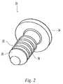
- FIG. 2is a perspective view of a fixation element for use with the insertion device of FIG. 1 ;
- FIGS. 3–4illustrate the placement of a fixation element within a pre-drilled hole in bone
- FIG. 5is a cross-sectional view of another embodiment of an insertion device
- FIG. 6is a partial cross-sectional view of a portion of the device of FIG. 5 ;
- FIG. 8a cross-sectional view of the embodiment of FIG. 7 ;
- FIG. 9is a side view of a fixation element spacer for use with the insertion device of FIG. 7 ;
- FIG. 10is a perspective view of another embodiment of an insertion device.
- FIG. 11is a cross-sectional view of the embodiment of FIG. 10 .
- one preferred fixation element compatible with insertion device 10comprises a tack 20 having a shaft 22 integral with a head 24 at a proximal end thereof.
- the distal end of shaft 22has a conical nose 26 to facilitate the insertion of tack 20 into bone tissue.
- a plurality of circular ribs 28extend radially from the exterior of shaft 22 to prevent the removal of the tack from the bone tissue after it has been inserted.
- Head 24has an outer diameter greater than the diameter of shaft 22 and contacts or rests against the bone or bone plate when the tack is inserted into bone tissue.
- the tackis made from a resorbable material so that it remains in the bone tissue temporarily and is absorbed by the body.
- tack 20can have numerously different configurations and dimensions.
- different types of fixation elements altogethercan be used with insertion device 10 .
- biocompatible screws, nails, anchors, rivets, or other similar implantscan also be inserted using insertion device 10 .
- the insertion devicecan be used to fasten a plate 40 or other device to a bone 41 .
- a hole 42is pre-drilled in the bone tissue at the desired insertion location and the insertion device 10 is placed adjacent the insertion location and the conical nose 26 of tack 20 is inserted into hole 42 and then shaft 22 of tack 20 is driven into the bone tissue by applying force in the axial direction to the handle, such as by a person's hand.
- insertion device 10is withdrawn from the insertion location and tack 20 is separated from channel 18 .
- an alternate embodiment of an insertion device 50includes a handle 52 at a proximal end and a spring loaded elongate applicator extension 54 extending between distal end 56 and handle 52 .
- Extension 54comprises a spring cover 58 attached to handle 52 for housing spring 60 and a holding sleeve 62 coaxially attached to the distal end of spring cover 58 in a telescoping fashion for receiving a fixation element.
- Sleeve 62has slightly smaller external dimensions than the internal dimensions of cover 58 so that the proximal end of sleeve 62 can be inserted into the distal end of cover 58 and sleeve 62 can move in the axial direction with respect to cover 58 .
- Sleeve 62includes prongs 64 that interlock with ridges 66 on the interior of cover 58 so that when sleeve 62 is inserted into cover 58 , sleeve 62 is not inadvertently removed from cover 58 in the distal direction.
- sleeve 62has prongs 64 that are flexible and are collapsible or bendable into the interior of sleeve 62 so that sleeve 62 can be removed from cover 58 for cleaning, disassembly, or replacement.
- Prongs 64are biased radially outwardly so that sleeve 62 can be easily reattached by simply pushing the sleeve into the cover in the proximal direction.
- Pronged tip 68is generally flexible and when the distal end of sleeve 62 is pressed, the prongs of sleeve 62 flex around the head of a fixation element to pick up and retain the element. In this way, it is possible to pick up a relatively small fixation element in a simple, single action.
- a central channel 70extends within handle 52 and through extension 54 .
- a shaft member 72is housed within central channel 70 and extends generally the entire length of channel 70 within extension 54 and is preferably fixedly attached to handle 52 .
- Shaft 72is generally cylindrical and includes a base portion 74 that engages the interior of channel 70 within handle 52 preferably by press fit, a mid-section 76 having a smaller diameter than base portion 74 , and a tip portion 78 having a smaller diameter than mid-section 76 .
- a first shoulder 80is positioned at the transition of base portion 74 and mid-section 76 .
- Spring 60is housed within spring cover 58 and extends around mid-section 76 and is compressible between first shoulder 80 and the proximal end of sleeve 62 , biasing sleeve 62 axially in the distal direction.
- the method of operation or use of device 50is similar to the method described above with respect to device 10 .
- the insertion device 50is placed adjacent an insertion location with a pre-drilled hole in bone and the fixation element or tack is driven into the bone tissue by applying axial force in the distal direction to handle 52 , moving sleeve 62 in the proximal direction.
- spring 60biases sleeve 62 in the distal direction and shaft 72 is moved in the distal direction due to the force applied on the handle.
- sleeve 62when sleeve 62 is moved further in the proximal direction, such as by applying axial force in the distal direction during fixation element insertion, sleeve 62 is retracted within cover 58 and shaft 72 is forced in the distal direction through the distal end of sleeve 62 .
- Tip portion 78 of shaft 72engages the proximal end of a fixation element and separates the fixation element from pronged tip 68 and drives the fixation element into bone. In this way, the fixation element is automatically disengaged from distal end 56 of device 50 and there is no need to manually slide holding sleeve 58 or rock the insertion device to disengage the fixation element.
- insertion device 50can be removed from the insertion location and sleeve 62 will spring back to its original starting position, shown in FIG. 5 .
- shaft 72is moveable in the axial direction with respect to handle 52 .
- an alternate embodiment of an insertion device 90includes a central channel 92 that extends through device 90 for receiving fixation elements or tacks 94 .
- Channel 92can store a plurality of tacks 94 and when insertion device 90 is used, a sufficient supply of tacks are available for quick and easy insertion into bone.
- a handle 96is at a proximal end of device 90 and an elongate applicator extension 98 extends between a distal end 100 and handle 96 .
- the deviceonly needs to be loaded once, thereby reducing operating time.
- Each spacercan accommodate at least one fixation element at the distal end, and a plurality of spacers can be inserted into central channel 92 of insertion device 90 , each with a tack attached to the distal end.
- the spacersare aligned coaxially within central channel 92 such that each spacer 102 proximal end 104 is aligned to receive a distal end 106 of an adjacent spacer so that the spacers can be axially stacked in abutting relation within channel 92 , as shown in FIG. 8 .
- Each spacer 102comprises a cylindrical nose or tip portion 110 toward distal end 106 and has a diameter d. Tip portion 110 extends an axial distance 1 from an angled mid-section portion 112 .
- a shoulder 114is formed at the intersection of tip portion 110 and mid-section portion 112 .
- Back portion 116extends from mid-section portion 112 and includes a slot 118 extending around the outer periphery.
- Back portion 116is preferably substantially cylindrical having a diameter D and mid-section portion 112 is preferably substantially frusto-conical.
- Back portion 116 diameter Dis larger than tip portion 110 diameter d so that tip portion 110 of a spacer 102 can be accommodated within the interior of back portion 116 .
- shoulder 114extends radially beyond the perimeter of tip portion 110 and is configured and dimensioned to rest against or abut the proximal end 104 of back portion 116 .
- Mid-section portion 112 and back portion 116extend an axial distance L from shoulder 114 to proximal end 104 , and distance L is preferably greater than distance 1 . In this way, when a fixation element or tack 94 is attached to a tip portion of a first spacer and then inserted into the interior of a proximal end of a second spacer, there is sufficient space within the interior of the second spacer to accommodate the tip portion of the first spacer and a fixation element attached thereto.
- the spacers 102are individually moveable within channel 92 .
- spacers 102are advanced in the distal direction when an additional spacer is introduced into the proximal end of channel 92 .
- shoulder 114 of the spacer being insertedcontacts the proximal end 104 of the most proximal spacer in channel 92 and pushes or forces all of the spacers in the channel in the axial direction toward distal end 100 of device 90 .
- the most distal spacerextends from distal end 100 of driver 90 and the shaft of tack 94 extends beyond socket 108 of spacer 102 in a position ready to be inserted into bone.
- an elastic ring 120is positioned on the interior of channel 92 adjacent the proximal end for engaging slot 118 to prevent movement of the spacers in the proximal direction. Ring 120 extends radially inward into channel 92 and engages slot 118 of the most proximal spacer, and when channel 92 is full of spacers, the spacers do not move in the proximal direction.
- a tackis inserted in the bone tissue by means of an axial force exerted on the proximal end of the device, much the same as for device 10 of FIG. 1 .
- the deviceis removed from the insertion location thus separating the element from the distal most spacer at the distal end of the device, and leaving the tack in the bone.
- the now empty distal most spaceris then removed from the distal end of channel 92 and reinserted into the proximal end thereof, advancing the remaining spacers distally in the channel and moving the distal most spacer and tack to the distal end 100 of the device and ready to insert the tack.
- channel 92is configured to accommodate about ten spacers, however the invention is also applicable to different size insertion devices with various channel lengths to accommodate more or less spacers or fixation elements as desired. Similarly, differing spacer dimensions or fixation element dimensions can also influence the fixation element holding capacity of the insertion device. Also, it is not required that empty spacers be introduced into the proximal end of channel 92 , and spacers having tacks attached thereto can also be introduced, thereby providing a continuous supply of fixation elements.
- an alternate embodiment of an insertion device 130includes a handle 132 at the proximal end 134 and an elongate applicator extension 136 extends from handle 132 in the distal direction.
- Applicator extension 136has a central channel 138 for receiving a plurality of fixation elements or tacks 140 and a piston 142 is axially aligned with channel 138 and movable therein to advance the tacks in the distal direction.
- Piston 142is positioned at the proximal end of channel 138 and a tab 144 extends laterally from one side of piston 142 and through a longitudinal slot 146 in extension 136 .
- Tab 144includes a knurled or textured portion 148 for engaging a person's finger to allow for manual advancement of piston 142 within channel 138 .
- slot 146includes angled portions 150 and a spring (not shown) is attached to tab 144 to engage angled portions 150 of slot 146 and prevent piston 142 from moving in a proximal direction.
- Channel 138forms a fixation element supply chamber, and like the insertion device of FIGS. 7–8 , the fixation elements are attached to spacers 152 and are aligned coaxially within channel 138 to be inserted into bone tissue one at a time as described above.
- the configuration and design of the spacers 152 used with device 130are the same as spacer 102 shown in FIG. 9 .
- fixation elementsare held at the distal end of each spacer by the same interference or friction fit used in the device of FIGS. 7–8 .
- channel 138is configured to accommodate about four spacers, however the invention is also applicable to different size insertion devices with various channel lengths to accommodate more or less spacers or fixation elements as desired.
- piston 142In operation of insertion device 130 , the distal end of piston 142 interfaces engages the proximal end of the last or proximal most spacer aligned within channel 138 to force the spacer in the distal direction and advance all of the aligned spacers in the channel.
- piston 142 exteriorsubstantially corresponds to the interior of the mid-section and back portion of spacer 152 .
- piston 142is preferably generally cylindrical with a tapered portion 154 at the distal end and tapered portion 154 is angled to generally correspond to the interior of mid-section portion of spacer 152 .
Landscapes
- Health & Medical Sciences (AREA)
- Engineering & Computer Science (AREA)
- Surgery (AREA)
- Life Sciences & Earth Sciences (AREA)
- Orthopedic Medicine & Surgery (AREA)
- Mechanical Engineering (AREA)
- Molecular Biology (AREA)
- Medical Informatics (AREA)
- Heart & Thoracic Surgery (AREA)
- Animal Behavior & Ethology (AREA)
- General Health & Medical Sciences (AREA)
- Public Health (AREA)
- Veterinary Medicine (AREA)
- Biomedical Technology (AREA)
- Nuclear Medicine, Radiotherapy & Molecular Imaging (AREA)
- Surgical Instruments (AREA)
Abstract
Description
Claims (28)
Priority Applications (12)
| Application Number | Priority Date | Filing Date | Title |
|---|---|---|---|
| US09/866,841US7147641B2 (en) | 2001-05-30 | 2001-05-30 | Fixation element insertion device |
| JP2002592828AJP2004527345A (en) | 2001-05-30 | 2002-05-28 | Fixed element insertion device |
| PCT/US2002/016656WO2002096310A1 (en) | 2001-05-30 | 2002-05-28 | Insertion device for bone fixation elements |
| CA2448676ACA2448676C (en) | 2001-05-30 | 2002-05-28 | Insertion device for bone fixation elements |
| BR0210067-3ABR0210067A (en) | 2001-05-30 | 2002-05-28 | Devices for attaching a bone fastener, and a bone tack having a head portion and an insertion end to the bone, and device for retaining a fastener. |
| MXPA03010886AMXPA03010886A (en) | 2001-05-30 | 2002-05-28 | Insertion device for bone fixation elements. |
| HK04101748.9AHK1059872B (en) | 2001-05-30 | 2002-05-28 | Insertion device for bone fixation elements |
| EP02739422AEP1389964B1 (en) | 2001-05-30 | 2002-05-28 | Insertion device for bone fixation elements |
| DE60211509TDE60211509T2 (en) | 2001-05-30 | 2002-05-28 | INSERTION DEVICE FOR BONE FIXING ELEMENTS |
| AT02739422TATE326181T1 (en) | 2001-05-30 | 2002-05-28 | INSERTING DEVICE FOR BONE FIXATION ELEMENTS |
| ARP020102029AAR034061A1 (en) | 2001-05-30 | 2002-05-30 | A DEVICE TO JOIN A BONE FIXING ELEMENT |
| US10/992,259US8052691B2 (en) | 2001-05-30 | 2004-11-18 | Spring loaded fixation element insertion device |
Applications Claiming Priority (1)
| Application Number | Priority Date | Filing Date | Title |
|---|---|---|---|
| US09/866,841US7147641B2 (en) | 2001-05-30 | 2001-05-30 | Fixation element insertion device |
Publications (2)
| Publication Number | Publication Date |
|---|---|
| US20020193807A1 US20020193807A1 (en) | 2002-12-19 |
| US7147641B2true US7147641B2 (en) | 2006-12-12 |
Family
ID=25348536
Family Applications (1)
| Application Number | Title | Priority Date | Filing Date |
|---|---|---|---|
| US09/866,841Expired - LifetimeUS7147641B2 (en) | 2001-05-30 | 2001-05-30 | Fixation element insertion device |
Country Status (1)
| Country | Link |
|---|---|
| US (1) | US7147641B2 (en) |
Cited By (26)
| Publication number | Priority date | Publication date | Assignee | Title |
|---|---|---|---|---|
| US20040116895A1 (en)* | 2001-01-29 | 2004-06-17 | Ulrich Werth | Device for inserting a needle-shaped body into living tissue |
| US20040243139A1 (en)* | 2003-04-28 | 2004-12-02 | Lewis Derek S. | Multiple screw delivery apparatus |
| US20050070918A1 (en)* | 2001-05-30 | 2005-03-31 | Zwirnmann Ralph Fritz | Spring loaded fixation element insertion device |
| US20070088363A1 (en)* | 2005-10-19 | 2007-04-19 | Sdgi Holdings, Inc. | Instruments and methods for delivering multiple implants in a surgical procedure |
| US20070276403A1 (en)* | 2006-05-12 | 2007-11-29 | Sdgi Holdings, Inc. | Instruments and methods for delivering multiple implants |
| US20080140086A1 (en)* | 2006-12-07 | 2008-06-12 | Jesse Gabriel Moore | Gravity feed implant dispenser |
| US20080243135A1 (en)* | 2007-03-30 | 2008-10-02 | Robinson Randolph C | Driver-Fixator System, Method, and Apparatus |
| US20080255576A1 (en)* | 2007-02-01 | 2008-10-16 | Warsaw Orthopedic, Inc. | Multiple implant dispensing driver |
| US20090105718A1 (en)* | 2007-10-17 | 2009-04-23 | Warsaw Orthopedic , Inc. | Surgical instruments for use with break-off device and an assoicated surgical method |
| US7544208B1 (en) | 2004-05-03 | 2009-06-09 | Theken Spine, Llc | Adjustable corpectomy apparatus |
| US20100286703A1 (en)* | 2007-12-28 | 2010-11-11 | Mickey Morgan | tack or drive screw for securing a prosthesis to bone and associated instrumentation and method |
| US20100331852A1 (en)* | 2009-06-29 | 2010-12-30 | Neubardt Seth L | Tool device for inserting fasteners |
| US7918876B2 (en) | 2003-03-24 | 2011-04-05 | Theken Spine, Llc | Spinal implant adjustment device |
| US7976549B2 (en) | 2006-03-23 | 2011-07-12 | Theken Spine, Llc | Instruments for delivering spinal implants |
| US7988695B2 (en) | 2005-12-21 | 2011-08-02 | Theken Spine, Llc | Articulated delivery instrument |
| US8114427B2 (en) | 1998-09-11 | 2012-02-14 | Gerhard Schmidmaier | Biologically active implants |
| US20120172885A1 (en)* | 2011-01-03 | 2012-07-05 | Warsaw Orthopedic, Inc. | Surgical tack delivery system, method and kit |
| US8506636B2 (en) | 2006-09-08 | 2013-08-13 | Theken Spine, Llc | Offset radius lordosis |
| US20160281759A1 (en)* | 2015-03-24 | 2016-09-29 | Revell Gmbh | Connection System for Detachably Connecting Components and Kit With Such |
| US9775702B2 (en) | 2010-03-10 | 2017-10-03 | Smith & Nephew, Inc. | Composite interference screws and drivers |
| US9788828B2 (en) | 2013-03-15 | 2017-10-17 | Smith & Nephew, Inc. | Miniaturized dual drive open architecture suture anchor |
| US9808298B2 (en) | 2013-04-09 | 2017-11-07 | Smith & Nephew, Inc. | Open-architecture interference screw |
| US9808337B2 (en) | 2010-03-10 | 2017-11-07 | Smith & Nephew, Inc. | Composite interference screws and drivers |
| US9901355B2 (en) | 2011-03-11 | 2018-02-27 | Smith & Nephew, Inc. | Trephine |
| US20190105178A1 (en)* | 2017-10-05 | 2019-04-11 | Warsaw Orthopedic, Inc | Spinal implant system and method |
| US12059189B2 (en) | 2020-06-17 | 2024-08-13 | Arthrex, Inc. | Compression/reduction drivers for performing surgical methods |
Families Citing this family (5)
| Publication number | Priority date | Publication date | Assignee | Title |
|---|---|---|---|---|
| US8758367B2 (en)* | 2006-09-05 | 2014-06-24 | Smith & Nephew, Inc. | Anchor delivery system |
| US9801667B2 (en)* | 2007-12-07 | 2017-10-31 | Nexus Spine, L.L.C. | Instruments, tools, and methods for presson pedicle screws |
| US9526488B2 (en) | 2013-03-15 | 2016-12-27 | Smith & Nephew, Inc. | Fenestrated locking suture anchor assembly |
| CN103393463B (en)* | 2013-07-16 | 2016-06-22 | 江苏双羊医疗器械有限公司 | Screwdriver |
| JP6661577B2 (en)* | 2017-06-29 | 2020-03-11 | 株式会社ハイレックスコーポレーション | Tunnel device |
Citations (33)
| Publication number | Priority date | Publication date | Assignee | Title |
|---|---|---|---|---|
| DE2933141A1 (en) | 1978-10-06 | 1980-04-10 | Sulzer Ag | ANCHORING PIN FOR BONE IMPLANTS |
| US4402641A (en) | 1980-04-17 | 1983-09-06 | Itw Ateco Gmbh | Self centering fastener |
| US4776739A (en) | 1986-04-14 | 1988-10-11 | Illinois Tool Works Inc. | Plastic drive fastener |
| US4776328A (en) | 1986-04-15 | 1988-10-11 | Sulzer Brothers Limited | Bone nail and an instrument for implanting a bone nail |
| US4963144A (en) | 1989-03-17 | 1990-10-16 | Huene Donald R | Bone screw fixation assembly, bone screw therefor and method of fixation |
| US5071420A (en) | 1991-04-25 | 1991-12-10 | Depuy Du Pont Orthopaedics | Isometry testing device |
| US5139499A (en) | 1989-02-06 | 1992-08-18 | American Cyanamid Company | Screw and driver |
| FR2682587A1 (en) | 1991-10-21 | 1993-04-23 | Laboureau Jacques Philippe | LIGAMENTARY SURGICAL NAIL AND ASSOCIATED ANCILLARY INTRUMENTATION. |
| US5236431A (en) | 1991-07-22 | 1993-08-17 | Synthes | Resorbable fixation device with controlled stiffness for treating bodily material in vivo and introducer therefor |
| US5258016A (en) | 1990-07-13 | 1993-11-02 | American Cyanamid Company | Suture anchor and driver assembly |
| US5261914A (en) | 1987-09-02 | 1993-11-16 | Russell Warren | Surgical fastener |
| US5268001A (en) | 1990-09-25 | 1993-12-07 | Innovasive Devices, Inc. | Bone fastener |
| US5391170A (en) | 1991-12-13 | 1995-02-21 | David A. McGuire | Angled surgical screw driver and methods of arthroscopic ligament reconstruction |
| US5445641A (en) | 1991-05-10 | 1995-08-29 | Synthes | Storage and dispensing device for osteosynthetic fixation elements |
| US5522843A (en) | 1994-02-23 | 1996-06-04 | Orthopaedic Biosystems Limited, Inc. | Apparatus for attaching soft tissue to bone |
| US5578057A (en) | 1993-07-28 | 1996-11-26 | Mitek Surgical Products, Inc. | Anchoring device installation tool assembly and method |
| US5584860A (en) | 1995-02-15 | 1996-12-17 | Mitek Surgical Products, Inc. | Suture anchor loader and driver |
| US5590574A (en) | 1995-09-05 | 1997-01-07 | Lide; Thomas E. | Driver with automatic fastener feed |
| US5672038A (en) | 1995-11-20 | 1997-09-30 | Ford Global Technologies, Inc. | Fastener |
| US5683401A (en) | 1994-02-17 | 1997-11-04 | Arthrex, Inc. | Method and apparatus for installing a suture anchor through a hollow cannulated grasper |
| US5735854A (en) | 1996-04-12 | 1998-04-07 | Caron; Philippe | Device for applying a screw |
| EP0834281A1 (en)* | 1996-10-03 | 1998-04-08 | United States Surgical Corporation | System for suture anchor placement |
| US5741268A (en) | 1995-03-18 | 1998-04-21 | Schuetz; Frank-Ullrich | Tacking device and tacking nails for surgery |
| US5800109A (en) | 1997-05-13 | 1998-09-01 | Amifast Corporation | Fastener with a tapered section and a slot |
| US5814051A (en) | 1997-06-06 | 1998-09-29 | Mitex Surgical Products, Inc. | Suture anchor insertion system |
| US5893856A (en) | 1996-06-12 | 1999-04-13 | Mitek Surgical Products, Inc. | Apparatus and method for binding a first layer of material to a second layer of material |
| US5895396A (en) | 1995-06-15 | 1999-04-20 | Ethicon, Inc. | Surgical pins |
| US5901424A (en) | 1997-05-29 | 1999-05-11 | Rector; Charles W. | Trocar button |
| US5904685A (en) | 1997-04-11 | 1999-05-18 | Stryker Corporation | Screw sheath |
| US5906624A (en) | 1997-01-03 | 1999-05-25 | Mitek Surgical Products, Inc. | Suture threader assembly, suture anchor assembly, and method for threading suture |
| FR2777443A1 (en) | 1998-04-21 | 1999-10-22 | Tornier Sa | Ancillary instrument for fitting and removing an implant such as a suture anchor |
| US6007539A (en) | 1996-01-17 | 1999-12-28 | Axel Kirsch | Fastening nail |
| EP1090591A2 (en) | 1999-09-29 | 2001-04-11 | Ethicon, Inc. | Absorbable rivet/pin applier for use in surgical procedures |
- 2001
- 2001-05-30USUS09/866,841patent/US7147641B2/ennot_activeExpired - Lifetime
Patent Citations (35)
| Publication number | Priority date | Publication date | Assignee | Title |
|---|---|---|---|---|
| DE2933141A1 (en) | 1978-10-06 | 1980-04-10 | Sulzer Ag | ANCHORING PIN FOR BONE IMPLANTS |
| US4402641A (en) | 1980-04-17 | 1983-09-06 | Itw Ateco Gmbh | Self centering fastener |
| US4776739A (en) | 1986-04-14 | 1988-10-11 | Illinois Tool Works Inc. | Plastic drive fastener |
| US4776328A (en) | 1986-04-15 | 1988-10-11 | Sulzer Brothers Limited | Bone nail and an instrument for implanting a bone nail |
| US5261914A (en) | 1987-09-02 | 1993-11-16 | Russell Warren | Surgical fastener |
| US5139499A (en) | 1989-02-06 | 1992-08-18 | American Cyanamid Company | Screw and driver |
| US4963144A (en) | 1989-03-17 | 1990-10-16 | Huene Donald R | Bone screw fixation assembly, bone screw therefor and method of fixation |
| US5258016A (en) | 1990-07-13 | 1993-11-02 | American Cyanamid Company | Suture anchor and driver assembly |
| US5268001A (en) | 1990-09-25 | 1993-12-07 | Innovasive Devices, Inc. | Bone fastener |
| US5071420A (en) | 1991-04-25 | 1991-12-10 | Depuy Du Pont Orthopaedics | Isometry testing device |
| US5445641A (en) | 1991-05-10 | 1995-08-29 | Synthes | Storage and dispensing device for osteosynthetic fixation elements |
| US5236431A (en) | 1991-07-22 | 1993-08-17 | Synthes | Resorbable fixation device with controlled stiffness for treating bodily material in vivo and introducer therefor |
| FR2682587A1 (en) | 1991-10-21 | 1993-04-23 | Laboureau Jacques Philippe | LIGAMENTARY SURGICAL NAIL AND ASSOCIATED ANCILLARY INTRUMENTATION. |
| US5391170A (en) | 1991-12-13 | 1995-02-21 | David A. McGuire | Angled surgical screw driver and methods of arthroscopic ligament reconstruction |
| US5578057A (en) | 1993-07-28 | 1996-11-26 | Mitek Surgical Products, Inc. | Anchoring device installation tool assembly and method |
| US5683401A (en) | 1994-02-17 | 1997-11-04 | Arthrex, Inc. | Method and apparatus for installing a suture anchor through a hollow cannulated grasper |
| US5522843A (en) | 1994-02-23 | 1996-06-04 | Orthopaedic Biosystems Limited, Inc. | Apparatus for attaching soft tissue to bone |
| US5720766A (en) | 1994-02-23 | 1998-02-24 | Orthopaedic Biosystems Limited, Inc. | Apparatus for attaching soft tissue to bone |
| US5584860A (en) | 1995-02-15 | 1996-12-17 | Mitek Surgical Products, Inc. | Suture anchor loader and driver |
| US5741268A (en) | 1995-03-18 | 1998-04-21 | Schuetz; Frank-Ullrich | Tacking device and tacking nails for surgery |
| US5895396A (en) | 1995-06-15 | 1999-04-20 | Ethicon, Inc. | Surgical pins |
| US5590574A (en) | 1995-09-05 | 1997-01-07 | Lide; Thomas E. | Driver with automatic fastener feed |
| US5672038A (en) | 1995-11-20 | 1997-09-30 | Ford Global Technologies, Inc. | Fastener |
| US6007539A (en) | 1996-01-17 | 1999-12-28 | Axel Kirsch | Fastening nail |
| US5735854A (en) | 1996-04-12 | 1998-04-07 | Caron; Philippe | Device for applying a screw |
| US5893856A (en) | 1996-06-12 | 1999-04-13 | Mitek Surgical Products, Inc. | Apparatus and method for binding a first layer of material to a second layer of material |
| EP0834281A1 (en)* | 1996-10-03 | 1998-04-08 | United States Surgical Corporation | System for suture anchor placement |
| US5906624A (en) | 1997-01-03 | 1999-05-25 | Mitek Surgical Products, Inc. | Suture threader assembly, suture anchor assembly, and method for threading suture |
| US5904685A (en) | 1997-04-11 | 1999-05-18 | Stryker Corporation | Screw sheath |
| US5800109A (en) | 1997-05-13 | 1998-09-01 | Amifast Corporation | Fastener with a tapered section and a slot |
| US5901424A (en) | 1997-05-29 | 1999-05-11 | Rector; Charles W. | Trocar button |
| US5814051A (en) | 1997-06-06 | 1998-09-29 | Mitex Surgical Products, Inc. | Suture anchor insertion system |
| FR2777443A1 (en) | 1998-04-21 | 1999-10-22 | Tornier Sa | Ancillary instrument for fitting and removing an implant such as a suture anchor |
| EP1090591A2 (en) | 1999-09-29 | 2001-04-11 | Ethicon, Inc. | Absorbable rivet/pin applier for use in surgical procedures |
| EP1090591A3 (en) | 1999-09-29 | 2001-06-06 | Ethicon, Inc. | Absorbable rivet/pin applier for use in surgical procedures |
Cited By (40)
| Publication number | Priority date | Publication date | Assignee | Title |
|---|---|---|---|---|
| US10646622B2 (en) | 1998-09-11 | 2020-05-12 | Gerhard Schmidmaier | Biologically active implants |
| US8114427B2 (en) | 1998-09-11 | 2012-02-14 | Gerhard Schmidmaier | Biologically active implants |
| US20040116895A1 (en)* | 2001-01-29 | 2004-06-17 | Ulrich Werth | Device for inserting a needle-shaped body into living tissue |
| US20050070918A1 (en)* | 2001-05-30 | 2005-03-31 | Zwirnmann Ralph Fritz | Spring loaded fixation element insertion device |
| US8052691B2 (en)* | 2001-05-30 | 2011-11-08 | Synthes Usa, Llc | Spring loaded fixation element insertion device |
| US7918876B2 (en) | 2003-03-24 | 2011-04-05 | Theken Spine, Llc | Spinal implant adjustment device |
| US7461574B2 (en)* | 2003-04-28 | 2008-12-09 | Biomet Microfixation, Llc | Multiple screw delivery apparatus |
| US20040243139A1 (en)* | 2003-04-28 | 2004-12-02 | Lewis Derek S. | Multiple screw delivery apparatus |
| US7544208B1 (en) | 2004-05-03 | 2009-06-09 | Theken Spine, Llc | Adjustable corpectomy apparatus |
| US20070088363A1 (en)* | 2005-10-19 | 2007-04-19 | Sdgi Holdings, Inc. | Instruments and methods for delivering multiple implants in a surgical procedure |
| US7717921B2 (en) | 2005-10-19 | 2010-05-18 | Warsaw Orthopedic, Inc. | Instruments and methods for delivering multiple implants in a surgical procedure |
| US7988695B2 (en) | 2005-12-21 | 2011-08-02 | Theken Spine, Llc | Articulated delivery instrument |
| US7976549B2 (en) | 2006-03-23 | 2011-07-12 | Theken Spine, Llc | Instruments for delivering spinal implants |
| US7722623B2 (en) | 2006-05-12 | 2010-05-25 | Warsaw Orthopedic, Inc. | Instruments and methods for delivering multiple implants |
| US20070276403A1 (en)* | 2006-05-12 | 2007-11-29 | Sdgi Holdings, Inc. | Instruments and methods for delivering multiple implants |
| US8506636B2 (en) | 2006-09-08 | 2013-08-13 | Theken Spine, Llc | Offset radius lordosis |
| US20080140086A1 (en)* | 2006-12-07 | 2008-06-12 | Jesse Gabriel Moore | Gravity feed implant dispenser |
| US7967828B2 (en) | 2006-12-07 | 2011-06-28 | Warsaw Orthopedic, Inc. | Gravity feed implant dispenser |
| US20080255576A1 (en)* | 2007-02-01 | 2008-10-16 | Warsaw Orthopedic, Inc. | Multiple implant dispensing driver |
| US8105328B2 (en)* | 2007-02-01 | 2012-01-31 | Warsaw Orthopedic, Inc. | Multiple implant dispensing driver |
| US20080243135A1 (en)* | 2007-03-30 | 2008-10-02 | Robinson Randolph C | Driver-Fixator System, Method, and Apparatus |
| WO2008121617A3 (en)* | 2007-03-30 | 2009-12-30 | Randolph Robinson | Driver-fixator system, method, and apparatus |
| US20090105718A1 (en)* | 2007-10-17 | 2009-04-23 | Warsaw Orthopedic , Inc. | Surgical instruments for use with break-off device and an assoicated surgical method |
| US8323293B2 (en)* | 2007-12-28 | 2012-12-04 | Synthes Gmbh | Tack or drive screw for securing a prosthesis to bone and associated instrumentation and method |
| US20100286703A1 (en)* | 2007-12-28 | 2010-11-11 | Mickey Morgan | tack or drive screw for securing a prosthesis to bone and associated instrumentation and method |
| US8087325B2 (en) | 2009-06-29 | 2012-01-03 | Neubardt Seth L | Tool device for inserting fasteners |
| US20100331852A1 (en)* | 2009-06-29 | 2010-12-30 | Neubardt Seth L | Tool device for inserting fasteners |
| US9775702B2 (en) | 2010-03-10 | 2017-10-03 | Smith & Nephew, Inc. | Composite interference screws and drivers |
| US9788935B2 (en) | 2010-03-10 | 2017-10-17 | Smith & Nephew, Inc. | Composite interference screws and drivers |
| US9808337B2 (en) | 2010-03-10 | 2017-11-07 | Smith & Nephew, Inc. | Composite interference screws and drivers |
| US9283020B2 (en)* | 2011-01-03 | 2016-03-15 | Warsaw Orthopedic, Inc. | Surgical tack delivery system, method and kit |
| US9888952B2 (en) | 2011-01-03 | 2018-02-13 | Warsaw Orthopedic, Inc | Surgical tack delivery system, method and kit |
| US20120172885A1 (en)* | 2011-01-03 | 2012-07-05 | Warsaw Orthopedic, Inc. | Surgical tack delivery system, method and kit |
| US9901355B2 (en) | 2011-03-11 | 2018-02-27 | Smith & Nephew, Inc. | Trephine |
| US9788828B2 (en) | 2013-03-15 | 2017-10-17 | Smith & Nephew, Inc. | Miniaturized dual drive open architecture suture anchor |
| US9808298B2 (en) | 2013-04-09 | 2017-11-07 | Smith & Nephew, Inc. | Open-architecture interference screw |
| US20160281759A1 (en)* | 2015-03-24 | 2016-09-29 | Revell Gmbh | Connection System for Detachably Connecting Components and Kit With Such |
| US20190105178A1 (en)* | 2017-10-05 | 2019-04-11 | Warsaw Orthopedic, Inc | Spinal implant system and method |
| US10864089B2 (en)* | 2017-10-05 | 2020-12-15 | Warsaw Orthopedic, Inc. | Spinal implant system and method |
| US12059189B2 (en) | 2020-06-17 | 2024-08-13 | Arthrex, Inc. | Compression/reduction drivers for performing surgical methods |
Also Published As
| Publication number | Publication date |
|---|---|
| US20020193807A1 (en) | 2002-12-19 |
Similar Documents
| Publication | Publication Date | Title |
|---|---|---|
| US7147641B2 (en) | Fixation element insertion device | |
| US8052691B2 (en) | Spring loaded fixation element insertion device | |
| JP4159748B2 (en) | Fracture fixation system | |
| US5423860A (en) | Protective carrier for suture anchor | |
| CN105662503B (en) | Biceps tenodesis implants and delivery tools | |
| JP2002507140A (en) | Freely splittable surgical drilling guides and plates | |
| US6328746B1 (en) | Surgical screw and driver system | |
| US7201754B2 (en) | Device for installing an anchor in a bone | |
| CA2567396C (en) | Snap-lock for drill sleeve | |
| DK170571B1 (en) | Structure for stabilizing a femur fracture | |
| US20090105718A1 (en) | Surgical instruments for use with break-off device and an assoicated surgical method | |
| EP2765937B1 (en) | Orthopedic anchor assembly | |
| US12178487B2 (en) | Implant positioning devices and methods | |
| JP2010517690A (en) | Numerous implant ejection drivers | |
| CN105662504A (en) | Biceps tenodesis implants and delivery tools | |
| AU2021259279B2 (en) | Inserter for glenosphere | |
| EP4135609A1 (en) | Modular retaining screwdriver | |
| CA2448676C (en) | Insertion device for bone fixation elements | |
| US10820934B2 (en) | Surgical guidewire centering device | |
| US10603057B2 (en) | Sterilizable disposable surgical instrument for bone fusion surgery | |
| US11154337B2 (en) | Spinal screw handling | |
| HK1059872B (en) | Insertion device for bone fixation elements | |
| CN110584769A (en) | Gun type reduction forceps and instrument bag | |
| US20200352693A1 (en) | Package for the containment, handling, and delivery of interbody cages |
Legal Events
| Date | Code | Title | Description |
|---|---|---|---|
| AS | Assignment | Owner name:SYNTHES (U.S.A.), PENNSYLVANIA Free format text:ASSIGNMENT OF ASSIGNORS INTEREST;ASSIGNOR:CHEN, MICHAEL C.;REEL/FRAME:011916/0336 Effective date:20010530 | |
| STCF | Information on status: patent grant | Free format text:PATENTED CASE | |
| FEPP | Fee payment procedure | Free format text:PAYOR NUMBER ASSIGNED (ORIGINAL EVENT CODE: ASPN); ENTITY STATUS OF PATENT OWNER: LARGE ENTITY | |
| AS | Assignment | Owner name:SYNTHES USA, LLC, PENNSYLVANIA Free format text:CHANGE OF NAME;ASSIGNOR:SYNTHES (U.S.A.);REEL/FRAME:022214/0552 Effective date:20081223 Owner name:SYNTHES USA, LLC,PENNSYLVANIA Free format text:CHANGE OF NAME;ASSIGNOR:SYNTHES (U.S.A.);REEL/FRAME:022214/0552 Effective date:20081223 | |
| FPAY | Fee payment | Year of fee payment:4 | |
| FPAY | Fee payment | Year of fee payment:8 | |
| MAFP | Maintenance fee payment | Free format text:PAYMENT OF MAINTENANCE FEE, 12TH YEAR, LARGE ENTITY (ORIGINAL EVENT CODE: M1553) Year of fee payment:12 |