US7147604B1 - High Q factor sensor - Google Patents
High Q factor sensorDownload PDFInfo
- Publication number
- US7147604B1 US7147604B1US10/215,379US21537902AUS7147604B1US 7147604 B1US7147604 B1US 7147604B1US 21537902 AUS21537902 AUS 21537902AUS 7147604 B1US7147604 B1US 7147604B1
- Authority
- US
- United States
- Prior art keywords
- sensor
- pressure
- circuit
- substrate
- frequency
- Prior art date
- Legal status (The legal status is an assumption and is not a legal conclusion. Google has not performed a legal analysis and makes no representation as to the accuracy of the status listed.)
- Expired - Lifetime, expires
Links
Images


Classifications
- A—HUMAN NECESSITIES
- A61—MEDICAL OR VETERINARY SCIENCE; HYGIENE
- A61B—DIAGNOSIS; SURGERY; IDENTIFICATION
- A61B5/00—Measuring for diagnostic purposes; Identification of persons
- A61B5/02—Detecting, measuring or recording for evaluating the cardiovascular system, e.g. pulse, heart rate, blood pressure or blood flow
- A61B5/021—Measuring pressure in heart or blood vessels
- A61B5/0215—Measuring pressure in heart or blood vessels by means inserted into the body
- A—HUMAN NECESSITIES
- A61—MEDICAL OR VETERINARY SCIENCE; HYGIENE
- A61B—DIAGNOSIS; SURGERY; IDENTIFICATION
- A61B5/00—Measuring for diagnostic purposes; Identification of persons
- A61B5/0002—Remote monitoring of patients using telemetry, e.g. transmission of vital signals via a communication network
- A61B5/0031—Implanted circuitry
- A—HUMAN NECESSITIES
- A61—MEDICAL OR VETERINARY SCIENCE; HYGIENE
- A61B—DIAGNOSIS; SURGERY; IDENTIFICATION
- A61B2562/00—Details of sensors; Constructional details of sensor housings or probes; Accessories for sensors
- A61B2562/02—Details of sensors specially adapted for in-vivo measurements
- A61B2562/028—Microscale sensors, e.g. electromechanical sensors [MEMS]
Definitions
- This inventionrelates to chronically implanted sensors for wirelessly sensing pressure, temperature, and/or other physical properties within the human body. More particularly, the invention concerns a wireless, un-powered micromachined blood pressure sensor that can be delivered using endovascular or simple surgical techniques to the interior of a human artery.
- Systemic arterial blood pressure measurementprovides important diagnostic and health monitoring information, especially for people at risk for hypertension. Blood pressure is also an important measurement in most animal research studies. Intravascular measures of blood pressure, typically via a pressure sensor mounted on a catheter inserted directly into a blood vessel, are considered the “gold standard” for measurement accuracy; however, these intravascular measures require invasive surgery and patient immobilization and cannot be used for simple diagnostic or chronic measurements.
- Implanted sensorsprovide the most accurate measurement of blood pressure, as the measurement is direct and overcomes the drawbacks of the systems listed above. In the case of severe hypertension, renal insufficiency, or a critical care situation, the benefits of an implanted sensor would warrant the risks of percutaneous techniques. Furthermore, these systems could be implanted in less high risk patient populations when the patients undergo other similar procedures, such as angiography, stent deployment, or balloon angioplasty. Additionally, implantation of these systems in live animal research would provide an accurate and simple means of chronic blood pressure measurement.
- Implanted sensorswould also allow ambulatory measurements, which provide key insights into diurnal variations in blood pressure, and may provide key information into the underlying disease state and more accurate measurement of a patient's “true” blood pressure (i.e., outside the clinical setting, avoiding the “white coat hypertension” syndrome).
- a sensor or transducer placed within a blood vessel or immediately external to the vesselcan be used to record variations in blood pressure based on physical changes to a mechanical element within the sensor. This information is then transferred from the sensor to an external device that is capable of translating the data from the sensor into a measurable value that can be displayed.
- the drawback of this type of sensoris that there must be a physical connection between the sensor and the external device, thus limiting its use to acute settings.
- a sensor capable of measuring pressureis to use a capacitor that is assembled so that the capacitive plates will deform as a result of exposure externally applied stress. This deformation will result in a change in the capacitance that will be proportional to the applied stress.
- the primary limitation to these type of sensorsis that the fabrication methods used to manufacture them do not provide sufficient miniaturization to allow the sensors to be introduced and implanted into an artery using less invasive techniques and the materials used do not provide the appropriate biocompatibility and long term mechanical and electrical durability.
- MEMSMicro-Electro-Mechanical Systems
- a number of patentsdetail pressure sensors (some capacitive in nature, some manufactured using MEMS-based technology) that are specifically designed for implantation into the human body. These sensors suffer from many of the limitations already mentioned with the additional concern that they require either the addition of a power source to operate the device or a physical connection to a device capable of translating the sensor output into a meaningful display of a physiologic parameter.
- the device embodied by the Chubbuck patentis manufactured using conventional techniques, thus requiring surgical implantation and thus limiting its applicability to areas that are easily accessible to surgery (e.g., the skull).
- the senoris not specified as being manufactured using MEMS fabrication technology, and thus no provision is made for appropriate miniaturization of the device that would allow practical and safe introduction and delivery into the body using standard percutaneous approaches.
- An ideal method of accomplishing all of the above objectiveswould be to place a device capable of measuring pressure within or adjacent to an artery.
- a healthcare provider or patientwill obtain an immediate readout of blood pressure, which could averaged over time or tracked for diurnal variation.
- Kensey et alU.S. Pat. No. 6,015,386. While this sensor accomplishes some of the above objectives, it has multiple problems that would make its use impractical.
- the sensor disclosed in the Kensey patentrelies on a mechanical sensing element. Elements of this kind cannot be practically manufactured in dimensions that would allow for endovascular introduction.
- this type of pressure sensorwould be subject to many problems in use that would limit its accuracy and reliability.
- One examplewould be exposure of the mechanical sensing element to body fluids or tissue ingrowth that could disrupt its function.
- the devicefails to account for vascular remolding which would result in baseline drift and could render the device inoperable, as the device requires that the artery be permanently deformed by the clamping action of the sensing element.
- a biocompatible, wireless, un-powered pressure sensorthat for the purposes of introduction and delivery within the human artery can be manipulated into a smaller shape and size by rolling or folding it into a reduced diameter form and loaded into a small diameter catheter. Then, upon positioning the catheter in the desired location, the sensor can be deployed and secured to the interior of the artery.
- the present inventiondescribes a sensor that can be fabricated using micro-machining techniques and can be implanted into the human body using non-surgical methods for the measurement of physical parameters.
- Specific target locationscould include the interior or exterior of a blood vessel, such as the aorta (preferably just below the renal arteries), or the femoral or the brachial artery.
- the deviceis implanted in the arm (radial or brachial artery), as the relative proximity of these arteries to the surface allows for further reduction in sensor size and ease of taking a blood pressure reading.
- blood pressure measurements in the brachial arterycorrelate well with aortic blood pressures.
- the sensor according to the inventionis fabricated using MicroElectroMechanical Systems (MEMS) technology, which allows the creation of a flexible device that is small, accurate, precise, durable, robust, biocompatible, radiopaque and insensitive to changes in body chemistry, biology or external pressure. This device will not require the use of wires to relay pressure information externally nor need an internal power supply to perform its function.
- MEMSMicroElectroMechanical Systems
- the MEMS approach to sensor designlends itself to the fabrication of small, flat sensors that can be formed using biocompatible polymers as substrate materials.
- the pressure sensor described abovecan then be manipulated into a smaller shape and size by rolling, bending, or folding it into a cylindrical form. This smaller object can then be introduced into the arterial system using endovascular catheter techniques.
- the deviceOnce positioned in an artery, the device, either on its own or through the addition or inclusion of metallic elements fabricated from stainless steel or super-elastic or shape memory nitinol alloys, unfurls into a preferred flat shape.
- the metallic componentsmay also include anchors, hooks, harpoons, coils, barbs or other configurations designed to secure the pressure sensor to the arterial wall and resist displacement due to the interaction of flowing blood.
- appropriately biocompatible coatingsmay be applied to the surface of the sensor to prevent adhesion of biological substances to the sensor that could interfere with it proper function.
- the pressure sensorcan be manufactured using Micro-machining techniques that were developed for the integrated circuit industry.
- An example of this type of sensorfeatures an inductive-capacitive (LC) resonant circuit with a variable capacitor and is described in Allen et al., U.S. Pat. No. 6,111,520, incorporated herein by reference.
- LCinductive-capacitive
- the pressure sensoris made of completely passive components having no active circuitry or power sources such as batteries.
- the pressure sensoris completely self-contained, having no leads to connect to an external circuit or power source.
- these same manufacturing techniquescan be used to add additional sensing capabilities, such as the ability to measure temperature by the addition of a resistor to the basic LC circuit.
- the pressure sensorWhen introduced into artery, the pressure sensor can provide pressure related data by use of an external measuring device.
- an external measuring deviceAs disclosed in the Allen et al. patent, several different excitation systems can be used.
- the sensorcan be electromagnetically coupled to a transmitting antenna. Consequently, a current is induced in the sensors, which oscillates at the resonant frequency of the sensor. This oscillation causes a change in the frequency spectrum of the transmitted signal. From this change, the bandwidth and resonant frequency of the particular sensor may be determined, from which the corresponding change in pressure can be calculated.
- the present inventionprovides for an impedance system and method of determining the resonant frequency and bandwidth of a resonant circuit within a particular sensor.
- the systemincludes a transmitting antenna, which is coupled to an impedance analyzer.
- the impedance analyzerapplies a constant voltage signal to the transmitting antenna scanning the frequency across a predetermined spectrum.
- the current passing through the transmitting antennaexperiences a peak at the resonant frequency of the sensor.
- the resonant frequency and bandwidthare thus determined from this peak in the current.
- the method of determining the resonant frequency and bandwidth using an impedance approachmay include the steps of transmitting an excitation signal using a transmitting antenna and electromagnetically coupling a sensor having a resonant circuit to the transmitting antenna thereby modifying the impedance of the transmitting antenna. Next, the step of measuring the change in impedance of the transmitting antenna is performed, and finally, the resonant frequency and bandwidth of the sensor circuit are determined.
- the present inventionprovides for a transmit and receive system and method for determining the resonant frequency and bandwidth of a resonant circuit within a particular sensor.
- an excitation signal of white noise or predetermined multiple frequenciesis transmitted from a transmitting antenna, the sensor being electromagnetically coupled to the transmitting antenna.
- a currentis induced in the resonant circuit of the sensor as it absorbs energy from the transmitted excitation signal, the current oscillating at the resonant frequency of the resonant circuit.
- a receiving antennaalso electromagnetically coupled to the transmitting antenna, receives the excitation signal minus the energy which was absorbed by the sensor.
- the power of the received signalexperiences a dip or notch at the resonant frequency of the sensor.
- the resonant frequency and bandwidthare determined from this notch in the power.
- the transmit and receive method of determining the resonant frequency and bandwidth of a sensor circuitincludes the steps of transmitting a multiple frequency signal from a transmitting antenna, and, electromagnetically coupling a resonant circuit on a sensor to the transmitting antenna, thereby inducing a current in the sensor circuit. Next, the step of receiving a modified transmitted signal due to the induction of current in the sensor circuit is performed. Finally, the step of determining the resonant frequency and bandwidth from the received signal is executed.
- Yet another system and method for determining the resonant frequency and bandwidth of a resonant circuit within a particular sensorincludes a chirp interrogation system.
- This systemprovides for a transmitting antenna which is electromagnetically coupled to the resonant circuit of the sensor.
- An excitation signal of white noise or predetermined multiple frequenciesis applied to the transmitting antenna for a predetermined period of time, thereby inducing a current in the resonant circuit of the sensor at the resonant frequency.
- the systemlistens for a return signal which radiates from the sensor.
- the resonant frequency and bandwidth of the resonant circuitare determined from the return signal.
- the chirp interrogation method for determining the resonant frequency and bandwidth of a resonant circuit within a particular sensorincludes the steps of transmitting a multi-frequency signal pulse from a transmitting antenna, electromagnetically coupling a resonant circuit on a sensor to the transmitting antenna, thereby inducing a current in the sensor circuit, listening for and receiving a return signal radiated from the sensor circuit, and determining the resonant frequency and bandwidth from the return signal.
- the present inventionprovides an analog system and method for determining the resonant frequency of a resonant circuit within a particular sensor.
- the analog systemcomprises a transmitting antenna coupled as part of a tank circuit which in turn is coupled to an oscillator.
- a signalis generated which oscillates at a frequency determined by the electrical characteristics of the tank circuit.
- the frequency of this signalis further modified by the electromagnetic coupling of the resonant circuit of a sensor.
- This signalis applied to a frequency discriminator which in turn provides a signal from which the resonant frequency of the sensor circuit is determined.
- the analog method for determining the resonant frequency and bandwidth of a resonant circuit within a particular sensorincludes the steps of generating a transmission signal using a tank circuit which includes a transmitting antenna, modifying the frequency of the transmission signal by electromagnetically coupling the resonant circuit of a sensor to the transmitting antenna, and converting the modified transmission signal into a standard signal for further application.
- a simple method of monitoring the pressure within a human artery by inserting a pressure transducer using a catheter and using a small, hand-held read device to measure the pressure easily, safely, inexpensively and accuratelyis disclosed. Also included is a method of introducing the sensor into the body by using the steps of folding or rolling the sensor into a cylinder, loading it into a catheter and deploying into the artery by allowing it to unroll or unfold, either by itself or preferably facilitated by the incorporation of a super-elastic alloy component. The same super-elastic element also provides the means to permanently securing the device to the interior of the artery.
- Delivery of the device of the invention to an arterymay be accomplished as follows: Using the standard Seldinger technique, the physician gains access to the patient's artery and places a vessel introducer with a hemostatic valve. A coaxial delivery catheter consisting of two hollow extruded polymeric catheters, the smaller of the two disposed inside the larger one, is inserted through the introducer and advanced distally until its tip is located in the segment of the artery within which it is desirable to place the sensor. The smaller catheter has an annular space to hold a folded sensor, which is released when the outer catheter is withdrawn proximally.
- the senorcan be loaded into the annular space between two, inner and outer catheters by inserting the sensor into a longitudinal slit cut into the outer catheter and attaching a tab on the sensor's surface into a slot cut into the inner coaxial catheter.
- the sensorBy rotation of the inner tube, the sensor will be retracted through the slit and positioned in the annular space between the two tubes.
- the rotation of the inner tubeis reversed and the sensor emerges through the slit of the outer catheter.
- the sensorcan be packaged and stored in a flat configuration.
- the second advantageis that by cutting the longitudinal slit at angle that is offset from the main axis of the outer tube, the sensor will be biased into a planar configuration as it is forced through the slit during the deployment process.
- the senor(ring shaped or flat) could be crimped or otherwise mounted on an intravascular balloon catheter, common in the art, and delivered to the target location. This balloon catheter is then inflated, forcing the sensor in contact with the vessel wall where it attaches as previously described.
- a further alternate delivery modewould be to load a folded sensor within a self-expanding stent constructed from a thermal memory metal such as nitinol.
- a self-expanding stentconstructed from a thermal memory metal such as nitinol.
- thermal memory metalsuch as nitinol.
- the nitinol stentwould be introduced into the artery and allowed to expand using the standard techniques. As the stent expands, the sensor would unfold into its desirable flat shape.
- the stentwhich is held fixed against the arterial wall due to the self-expanding nature of the nitinol materials exerting a constant circumferential force, serves as the mechanism to keep the sensor fixed in a specific position within the vasculature.
- a sensor according to the inventioncould be attached to and implanted or inserted in combination with a vascular closure device, such as are commonly used after a procedure such as angioplasty.
- the sensorcould be positioned within or attached to a sealing plug or member that is positioned within the artery that is sealed.
- a smaller version of the sensorcan be injected into a site within the patient's vasculature wherein the sensor would lodge in a minor artery or capillary.
- a small sensorcould be injected to a site in or near a patient's lung where the sensor would be positioned in the capillaries that lead to the patient's pulmonary artery, to measure pressure. The resulting information would calculate closely to the actual pressure of the patient's pulmonary artery.
- FIG. 1is a front view of an embodiment of the invention
- FIG. 2is a lateral view of the embodiment of the invention shown in FIG. 1 ;
- FIG. 3is a lateral view of an embodiment of the invention of FIG. 1 folded for delivery;
- FIG. 4is a front view of another embodiment of the invention.
- FIG. 5is a lateral view of a yet further embodiment of the invention.
- FIGS. 6 and 7are each a lateral view of an embodiment of the invention with an anchoring mechanism
- FIG. 8is an exploded schematic representation of construction of one embodiment of a sensor
- FIG. 9is a schematic representation of an embodiment of the invention with distributed capacitance
- FIGS. 10 and 11are each a schematic, partial cross-sectional view of an embodiment of a sensor according to the invention.
- FIG. 12is a schematic representation of an alternate shape for an embodiment of the invention.
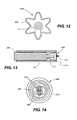
- FIG. 13is a cross-sectional view of the distal end of a delivery catheter with the embodiment shown in FIG. 12 ;
- FIG. 14is a schematic of another sensor according to the invention.
- FIG. 15is a schematic representation of another, preferred embodiment of the invention.
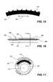
- FIG. 16is a partly cross-sectional view of a preferred delivery system according to the invention.
- FIG. 17is a cross-sectional view of FIG. 16 along the line 17 — 17 ;
- FIG. 18is a partly cross-sectional view of the delivery system of FIG. 16 with an inflated balloon
- FIG. 19is a longitudinal cross-sectional view of a delivered sensor
- FIG. 20is a cross-sectional view of FIG. 19 along the line 20 — 20 ;
- FIG. 21is a drawing of a read-out device employed according to the invention.
- FIG. 22is a block diagram of an electrical circuit useful according to the invention.
- FIGS. 1 , 2 , and 3One embodiment of a sensor according to the invention is shown in FIGS. 1 , 2 , and 3 , where a disc-shaped sensor 10 comprises a capacitor disk 12 and a wire spiral 14 .
- FIG. 2is a lateral view of sensor 10
- FIG. 3is a lateral view of sensor 10 in a folded configuration for insertion.
- the fact that sensor 10 is sufficiently flexible to be folded as shown in FIG. 4is an important aspect of the invention.
- a ring 20 comprised of a shape memory alloy such as nitinolhas been attached to, for example, with adhesive, or incorporated into, for example, layered within, a sensor 22 .
- FIG. 5is a lateral cross-sectional view of a circular sensor 30 having a ring 32 comprised of a shape memory alloy such as nitinol encompassing the outer edge 34 of sensor 30 .
- Ring 32preferably is attached to outer edge 34 by a suitable physiologically acceptable adhesive 36 , such as an appropriate epoxy or cyanoacrylate material.
- a suitable physiologically acceptable adhesive 36such as an appropriate epoxy or cyanoacrylate material.
- the ringwill be radiopaque.
- the size of the circular sensors of the inventionwill vary according to factors such as the intended application, the delivery system, etc.
- the circular sensorsare intended to be from about 0.5 to about 3 cm in diameter, with a thickness of from about 0.05 to about 0.30 in.
- the thickness of the ringi.e., the width of the outside surface 38 , will preferably be from about 1.5 to about 3.5 times the thickness of the sensor.
- FIGS. 6 and 7each represent a lateral view of a sensor with an anchoring member.
- sensor 40has a screw/coil 42
- sensor 40has an anchor 44 with umbrella-like projections 46 .
- anchor 42 or 44When pressure is applied to the flat side 48 of sensor 40 , anchor 42 or 44 will penetrate a vessel wall, organ wall, or other substrate to cause sensor 36 to remain in a desired position or location.
- an anchoring mechanismsuch as is shown in FIGS. 6 and 7 could be attached to ring 32 in FIG. 5 .
- the pressure sensor of the inventioncan be manufactured using Micro-machining techniques that were developed for the integrated circuit industry.
- An example of this type of sensorfeatures an inductive-capacitive (LC) resonant circuit with a variable capacitor, as is described in Allen et al., U.S. Pat. No. 6,111,520, all of which is incorporated herein by reference.
- the sensorcontains two types of passive electrical components, namely, an inductor and a capacitor.
- the sensoris constructed so that the fluid pressure at the sensor's surface changes the distance between the capacitor's parallel plates and causes a variation of the sensor's capacitance.
- the senor of the inventionis constructed by laminating several layers of material together, as shown, for example, in FIG. 8 .
- a first layer 142is fabricated from a sheet of polyimide film (e.g., KAPTON, available from Du Pont) upon which a micro-machined copper pattern 144 is deposited.
- Pattern 144preferably consists of a circular conductive segment in the center of the sheet surrounded by a spiral coil.
- a second layer 148comprises a sheet of flexible adhesive through which hole 150 has been cut in the center. (Optionally there may be more than one such layer 148 .)
- a final layer 152is another sheet of polyimide film with a copper pattern 154 that is a mirror image of pattern 144 .
- the first, second, and third layersare aligned such that the holes in the middle adhesive layers are centered between the circular conductive segments in the middle of the two outer polyimide layers 142 and 152 .
- a capacitordefined as an electric circuit element used to store charge temporarily, consisting in general of two metallic plates separated and insulated from each other by a dielectric
- the two metal spirals on the polyimide sheets 142 and 152form an inductor component of a miniature electrical circuit.
- the sensorexhibits the electrical characteristics associated with a standard LC circuit.
- An LC circuitis simply a closed loop with only two elements, a capacitor and an inductor. If a current is induced in the LC loop, the energy in the circuit is shared back and forth between the inductor and capacitor. The result is an energy oscillation that will vary at a specific frequency. This is termed the resonant frequency of the circuit and it can be easily calculated as its value is dependent on the circuit's inductance and capacitance. Therefore, a change in capacitance will cause the frequency to shift higher or lower in linear proportion to the change in the value of capacitance.
- the capacitor in the assembled pressure sensorconsists of the two circular conductive segments separated by an air gap. If a pressure force is exerted on these segments it will act to deform the outer polyimide sheet and move the two conductive segments closer together. This will have the effect of reducing the air gap between them which will consequently change the capacitance of the circuit. The result will be a shift in the circuit's resonant frequency that will be in direct proportion to the force applied to the sensor's surface.
- the inductorBecause of the presence of the inductor, it is possible to electromagnetically couple to the sensor and induce a current in the circuit. This allows for wireless communication with the sensor and the ability to operate it without the need for an internal source of energy such as a battery.
- the sensorif the sensor is located within the interior of an artery, it will be possible to determine the pressure of blood within the artery in a simple, non-invasive procedure by remotely interrogating the sensor, recording the resonant frequency and converting this value to a pressure measurement.
- the readout devicegenerates electromagnetic energy that penetrates through the body's tissues to the sensor's implanted location.
- the sensor's electrical componentsabsorb a fraction of the electromagnetic energy that is generated by the readout device via inductive coupling.
- This couplinginduces a current in the sensor's circuit oscillates at the same frequency as the applied electromagnetic energy. Due to the nature of the sensor's electromechanical system there exists a frequency of alternating current at which the absorption of energy from the readout device is at a minimum. This frequency is a function of the capacitance of the device. Therefore, if the sensor's capacitance changes, so will the frequency at which it minimally absorbs energy from the readout device. Since the sensor's capacitance is mechanically linked to the fluid pressure at the sensor's surface, a measurement of this frequency by the readout device gives a relative measurement of the fluid pressure. If calibration of the device is performed, then an absolute measurement of pressure can be made. See, for example, the extensive discussion in the Allen et al. patent, again incorporated herein by reference, as well as Gershenfeld et al., U.S. Pat. No. 6,025,725, incorporated herein by reference.
- the pressure sensoris made of completely passive components having no active circuitry or power sources such as batteries.
- the pressure sensoris completely self-contained having no leads to connect to an external circuit or power source. Furthermore, these same manufacturing techniques can be used to add additional sensing capabilities, such as the ability to measure temperature by the addition of a resistor to the basic LC circuit.
- the capacitor elementconsists of two plates that are separated by a suitable dielectric material, such as air, inert gas, fluid or a vacuum.
- a suitable dielectric materialsuch as air, inert gas, fluid or a vacuum.
- various coatingscould be applied to the surface or between the polymeric layers used to form the sensor. These coating can be used to provide a hermetic seal that will prevent leakage of body fluids into the cavity or permeation of the cavity material (gas, vacuum or fluid) out of the sensor.
- a sensor 170has a multitude of capacitors 175 formed either as separate elements or as an array. In such a distributed capacitance configuration, there can be a more accurate and more sensitive measurement of pressure.
- the frequency response to the sensorwill be in the range of from about 1 to about 200 MH z , preferably from about 1 to about 100 MH z , and more preferably from about 2 to about 90 MH z , with a Q factor from about 5 to about 80, preferably from about 10 to about 70, more preferably from about 10 to 60.
- the deviceis constructed using multiple layers upon lie the necessary circuit elements. Disposed on the top and bottom layer are metal patterns constructed using micro-machining techniques which define a top and bottom conductor and a spiral inductor coil. To provide for an electrical contact between the top and bottom layers small vias or holes are cut through the middle layers. When the layers are assembled, a metal paste is forced into the small vias to create direct electrical connections or conduits.
- a vialess operational LC circuitcan be created. This absence of via holes represents a significant improvement to the sensor in that it simplifies the manufacturing process and, more importantly, significantly increases the durability of the sensor making it more appropriate for use inside the human body.
- FIG. 10is a partial cross-sectional review of the sensor shown in FIG. 8 , where first layer 142 , second layer 148 , and third layer 152 are sandwiched together.
- a cylindrical space 156comprises a pressure sensitive capacitor. No via holes are present.
- the sensor 178 shown in FIG. 11comprises a first polyimide layer 180 , a second, adhesive layer 182 , and a third, polyimide layer 184 .
- First layer 180has a copper pattern comprising a coil 186 and a disk 188
- third layer 184comprises a coil 190 and a disk 192 .
- a cylindrical space 196comprises a pressure sensitive capacitor.
- a diode 194 connected between coils 186 and 190creates a non-linear sensor, i.e., a sensor where the frequency change is non-linear as compared to a change in pressure.
- the design of the sensoris not limited to a specific geometric configuration.
- the inductor componentis described as a spiral coil.
- Other embodiments of the sensorcould utilize oval, rectangular or an amorphous shape.
- Specific electrical, mechanical and biologic advantagescould be obtained by employing these various geometric designs.
- a rectangular shaped sensor in which the ratio of length to width was greater than fourwould greater lend itself to catheter based delivery as is would minimize the radius of curvature required to position the folded device within a small diameter catheter.
- a more elaborate shapesuch as one resembling the petals of a flower, would lend itself to more complex folding patterns that could facilitate delivery to specific anatomical location within an artery. For example, in FIGS.
- a flower-shaped sensor 208has a capacitor surface 210 connected to a wire 212 that partly follows the outer configuration of sensor 208 .
- Petals 214fold so that sensor 208 with a distal anchor 216 can be “loaded” into a catheter 218 .
- a pushing rod member 222is pushed distally to cause sensor 208 to be released from catheter 218 and attach to the inner surface of an artery (not shown).
- a foldable sensoris delivered to a patient's artery in the distal end of a delivery catheter.
- the sensorcan be regularly- or irregularly-shaped so that outer portions of the sensor can fold to about a 90° angle as compared to a relatively flat, middle portion of the sensor.
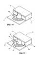
- FIG. 12Another embodiment of a sensor is shown in FIG. 12 , where circular sensor 230 comprises flexible cut-outs 232 .
- the first outer layer 234comprises a polymide substrate with a copper pattern comprising a coil 240 and several, from 2 to 6, disks 242 to form pressure sensitive capacitors.
- Sensor 230also comprises at least one adhesive layer (not shown) and a third outer layer corresponding to the first outer layer (not shown).
- sensor 230has at least one diode connecting the copper coils of the first and third layers.
- the flexible cut-outs 232facilitate, among other things, folding of sections of sensor 230 for placement in, or arrangement upon, a delivery catheter, such as in FIG. 13 .
- the sectionscan also be folded to create either a “Z” shape or, for example, a “U” shape, for other applications. It is within the scope of the invention that variously numbered and shaped cut-outs could be used for particular applications.
- a pressure sensor 250has a slightly curved cross-section in a lateral direction 252 .
- sensor 250has projections 254 , which are preferably comprised of a rigid or semi-rigid metallic or polymeric material.
- Balloon dilatation catheter 258which comprises a catheter shaft 260 and a dilatation balloon 262 .
- Balloon dilatation catheter 258has a lumen 264 , so that balloon dilatation catheter 258 can be advanced over guidewire 266 to a position within an artery 268 , as shown in FIG. 16 .
- a cross-sectional view across line 17 — 17 in FIG. 17shows sensor 250 positioned within folds 270 of dilatation balloon 262 .
- dilatation balloon 262 of dilatation balloon catheter 258has been inflated to press the outer surface of sensor 250 against the inner wall 272 of artery 268 .
- sensor 250remains, attached to inner wall 272 .
- a lateral cross-sectional view across line 20 — 20is shown in FIG. 20 .
- QQuality factor
- the transmitted energywill decay exponentially as it travels away from the sensor, the lower the energy available to be transmitted, the faster it will decay below a signal strength that can be detected by the receiving antenna and the closer the sensor needs to be situated relative to the receiving electronics. In general then, the lower the Q, the greater the energy loss and the shorter the distance between sensor and receiving antenna.
- the Q of the sensorwill be dependent on multiple factors such as the shape, size, diameter, number of turns, spacing between turns and cross-sectional area of the inductor component.
- Qwill be greatly affected by the materials used to construct the sensors. Specifically, materials with low loss tangents will provide the sensor with higher Q factors.
- the implantable sensor accending to the inventionis preferably constructed of various polymers that provide the required flexibility, biocompatibility and processing capabilities.
- the materials usedare flexible, biocompatible, and result in a high Q factor.
- KAPTONa polyimide
- suitable materialsinclude polyimides, polyesters (e.g., polyethylene terephthalate), liquid crystal polymers (LCP), and polytetrafluoroethylene (PTFE) and co-polymers thereof.
- liquid crystal polymersexamples include, but are not limited to, wholly aromatic polyesters such as polybenzoate-naphthalate; polybenzoate-terephthalate; bisphenol-isophthalate; polybenzoate-terephthalate-ethylene glycol; and polynaphthalate-amino terephthate.
- dielectricsthat is, they are poor conductors of electricity (have a low dielectric constant), but are efficient supporters of electrostatic fields.
- An important property of dielectric materialsis their ability to support an electrostatic field while dissipating minimal energy. The lower the dielectric loss (the proportion of energy lost), the more effective the dielectric material. For a lossy dielectric material, the loss is described by the property termed “loss tangent.” A large loss tangent reflects a high degree of dielectric absorption.
- the middle layercan comprise an adhesive.
- adhesivesinclude flexible, biocompatible materials such as an epoxy or acrylic adhesive.
- LCPs and PTFEhave the lowest loss tangents, and construction of pressures sensors from these materials produces the highest Q factor.
- an LC circuit pressure sensor similar to the embodiment shown in FIG. 8was assembled using successive layers of the following materials: polyimide/copper, acrylic adhesive, polyimide, acrylic adhesive, and copper/polyamide. When electrically characterized, the Q of this sensor was approximately 30.
- a second sensor of the exact same geometrywas then fabricated using the following alternate construction: LCP/copper, PTFE/epoxy adhesive (speedboard), and copper/LCP. When tested, this sensor demonstrated a Q factor of 48.
- the sensor constructioncould be LCP/copper, LCP, copper/LCP. This sensor would be easier to construct and would also have even an higher Q factor.
- potential encapsulation materialmust have the flexibility and biocompatibility characteristics of the sensor material and also be sufficiently compliant to allow transmission of fluid pressure to the pressure sensitive diaphragm.
- a preferred material for this applicationis polydimethylsiloxane (silicone).
- a thin (i.e., 200 micron) coating of siliconewas applied to the LCP sensor detailed above.
- This coatingprovided sufficient insulation to maintain the Q at 40 in a conductive medium. Equally important, despite the presence of the silicone, adequate sensitivity to pressure changes was maintained and the sensor retained sufficient flexibility to be folded for endovascular delivery.
- One additional benefit of the silicone encapsulation materialis that it can be loaded with a low percentage (i.e., 10–20%) of radio-opaque material (e.g., barium sulfate) to provide visibility when examined using fluoroscopic x-ray equipment. This added barium sulphate will not affect the mechanical and electrical properties of the silicone.
- the Q factor of a sensorit is desirable to increase the Q factor of a sensor, and the Q factor can be increased by suitable selection of sensor materials or a coating, or both. Preferably both are used, because the resulting high Q factor of a sensor prepared in this fashion is especially suitable for the applications described.
- the pressure sensorWhen introduced into the artery, the pressure sensor can provide pressure-related data by use of an external measuring device.
- an external measuring deviceAs disclosed in the Allen et al. patent, several different excitation systems can be used.
- the readout devicegenerates electromagnetic energy that can penetrate through the body's tissues to the sensor's implanted location.
- the sensor's electrical componentscan absorb a fraction of the electromagnetic energy that is generated by the readout device via inductive coupling. This coupling will induce a current in the sensor's circuit that will oscillate at the same frequency as the applied electromagnetic energy. Due to the nature of the sensor's electro-mechanical system there will exist a frequency of alternating current at which the absorption of energy from the readout device is at a minimum. This frequency is a function of the capacitance of the device.
- the sensor's capacitancechanges so will the frequency at which it minimally absorbs energy from the readout device. Since the sensor's capacitance is mechanically linked to the fluid pressure at the sensor's surface, a measurement of this frequency by the readout device can give a relative measurement of the fluid pressure. If calibration of the device is performed then an absolute measurement of pressure can be made.
- the circuitry used to measure and display pressureis contained within a simple to operate, battery powered, hand-held electronic unit 300 , as shown in FIG. 21 .
- This unit 300also contains the antenna needed to perform the electromagnetic coupling to the sensor.
- the antennamay be integrated into the housing for the electronics or it may be detachable from the unit so that it can be positioned on the surface of the body 304 in proximity to the implanted sensor 302 and easily moved to optimize the coupling between antenna and sensor.
- the antennaitself may consist of a simple standard coil configuration or my incorporate ferrous elements to maximize the coupling efficiency.
- the electronic devicewould feature an LCD or LED display 306 designed to clearly display the recorded pressure in physiologically relevant units such as mm HG.
- the displaymay be created by integrating a commercially available hand-held computing device such as a Palm® or micro-PC into the electronic circuitry and using this device's display unit as the visual interface between the equipment and its operator.
- a further advantage of this approachis that the hand-held computer could be detached from the read-out unit and linked to a standard desktop computer. The information from the device could thus be downloaded into any of several commercially available data acquisition software programs for more detailed analysis or for electronic transfer via hard media or the internet to a remote location.
- the electronicscould be reduced is size such that they are capable of being formed into a band that could be placed around the wrist or leg directly above the location of the implanted sensor. In this manner, continuous readings of pressure could be made and displayed.
- the present inventionprovides for an impedance system and method of determining the resonant frequency and bandwidth of a resonant circuit within a particular sensor.
- the systemincludes a transmitting antenna, which is coupled to an impedance analyzer.
- the impedance analyzerapplies a constant voltage signal to the transmitting antenna scanning the frequency across a predetermined spectrum.
- the current passing through the transmitting antennaexperiences a peak at the resonant frequency of the sensor.
- the resonant frequency and bandwidthare thus determined from this peak in the current.
- the method of determining the resonant frequency and bandwidth using an impedance approachmay include the steps of transmitting an excitation signal using a transmitting antenna and electromagnetically coupling a sensor having a resonant circuit to the transmitting antenna thereby modifying the impedance of the transmitting antenna. Next, the step of measuring the change in impedance of the transmitting antenna is performed, and finally, the resonant frequency and bandwidth of the sensor circuit are determined.
- the present inventionprovides for a transmit and receive system and method for determining the resonant frequency and bandwidth of a resonant circuit within a particular sensor.
- an excitation signal of white noise or predetermined multiple frequenciesis transmitted from a transmitting antenna, the sensor being electromagnetically coupled to the transmitting antenna.
- a currentis induced in the resonant circuit of the sensor as it absorbs energy from the transmitted excitation signal, the current oscillating at the resonant frequency of the resonant circuit.
- a receiving antennaalso electromagnetically coupled to the transmitting antenna, receives the excitation signal minus the energy which was absorbed by the sensor.
- the power of the received signalexperiences a dip or notch at the resonant frequency of the sensor.
- the resonant frequency and bandwidthare determined from this notch in the power.
- the transmit and receive method of determining the resonant frequency and bandwidth of a sensor circuitincludes the steps of transmitting a multiple frequency signal from transmitting antenna, and, electromagnetically coupling a resonant circuit on a sensor to the transmitting antenna thereby inducing a current in the sensor circuit. Next, the step of receiving a modified transmitted signal due to the induction of current in the sensor circuit is performed. Finally, the step of determining the resonant frequency and bandwidth from the received signal is executed.
- Yet another system and method for determining the resonant frequency and bandwidth of a resonant circuit within a particular sensorincludes a chirp interrogation system.
- This systemprovides for a transmitting antenna which is electromagnetically coupled to the resonant circuit of the sensor.
- An excitation signal of white noise or predetermined multiple frequenciesis applied to the transmitting antenna for a predetermined period of time, thereby inducing a current in the resonant circuit of the sensor at the resonant frequency.
- the systemlistens for a return signal which radiates from the sensor.
- the resonant frequency and bandwidth of the resonant circuitare determined from the return signal.
- the chirp interrogation method for determining the resonant frequency and bandwidth of a resonant circuit within a particular sensorincludes the steps of transmitting a multi-frequency signal pulse from a transmitting antenna, electromagnetically coupling a resonant circuit on a sensor to the transmitting antenna thereby inducing a current in the sensor circuit, listening for and receiving a return signal radiated from the sensor circuit, and determining the resonant frequency and bandwidth from the return signal.
- FIG. 22A representative block diagram of an electrical circuit that can be used to interrogate the sensor and determine the resonant frequency is shown in FIG. 22 .
- a transmitter and receiveri.e., a transceiver 322 , has an antenna 324 for generating and receiving signals from a sensor 326 .
- Transceiver 322is an electronic or digital connection with a phase detector 330 , a microprocessor 332 , and a frequency synthesizer 334 .
- Microprocessor 332is in turn connected to an interface 336 such as a terminal.
- Power supply 338regulates and provides electrical power to the system.
- the present inventionalso provides an analog system and method for determining the resonant frequency of a resonant circuit within a particular sensor.
- the analog systemcomprises a transmitting antenna coupled as part of a tank circuit which in turn is coupled to an oscillator.
- a signalis generated which oscillates at a frequency determined by the electrical characteristics of the tank circuit.
- the frequency of this signalis further modified by the electromagnetic coupling of the resonant circuit of a sensor.
- This signalis applied to a frequency discriminator which in turn provides a signal from which the resonant frequency of the sensor circuit is determined.
- the analog method for determining the resonant frequency and bandwidth of a resonant circuit within a particular sensorincludes the steps of generating a transmission signal using a tank circuit which includes a transmitting antenna, modifying the frequency of the transmission signal by electromagnetically coupling the resonant circuit of a sensor to the transmitting antenna, and converting the modified transmission signal into a standard signal for further application.
- the inventionfurther includes an alternative method of measuring pressure in which a non-linear element such as a diode or polyvinylidenedifloride piezo-electric polymer, is added to the LC circuit.
- a non-linear elementsuch as a diode or polyvinylidenedifloride piezo-electric polymer
- a diode with a low turn-on voltagesuch as a Schottky diode can be fabricated using micro-machining techniques.
- the presence of this non-linear element in various configurations within the LC circuitcan be used to modulate the incoming signal from the receiving device and produce different harmonics of the original signal.
- the read-out circuitrycan be tuned to receive the particular harmonic frequency that is produced and use this signal to reconstruct the fundamental frequency of the sensor.
- the advantage of this approachis two-fold; the incoming signal can be transmitted continuously and since the return signal will be at different signals, the return signal can also be received continuously.
- One additional concern regarding devices designated for long term implantation in the human bodyis maintenance of electrical stability over time as the environment the sensor has been placed in changes. Under this scenario the sensor's accuracy may drift from its original baseline. It would thus be desirable to have available to the user of the device, a method for determining if the sensor is functioning properly and also to be able to recalibrate the device anytime after it has been implanted.
- This inventiontherefore also includes a method of using acoustic energy to challenge the sensor and determining to what degree (if any) sensor performance has been degraded. In this method, energy in the ultrasound range is directed towards the sensor and a measurement is made of the mechanical resonance of the sensor membrane. This same measurement can be made at point after the sensor has been implanted.
- a determination of the degree of change in mechanical resonance frequencycan be established. This value can then be used to create a calibration factor that can be applied to the pressure reading taken post-implantation in order to adjust the measured value to reflect the actual pressure within the artery.
Landscapes
- Health & Medical Sciences (AREA)
- Life Sciences & Earth Sciences (AREA)
- Engineering & Computer Science (AREA)
- Heart & Thoracic Surgery (AREA)
- Public Health (AREA)
- Veterinary Medicine (AREA)
- Biophysics (AREA)
- Pathology (AREA)
- Physics & Mathematics (AREA)
- Biomedical Technology (AREA)
- Cardiology (AREA)
- Medical Informatics (AREA)
- Molecular Biology (AREA)
- Surgery (AREA)
- Animal Behavior & Ethology (AREA)
- General Health & Medical Sciences (AREA)
- Vascular Medicine (AREA)
- Physiology (AREA)
- Computer Networks & Wireless Communication (AREA)
- Measuring Pulse, Heart Rate, Blood Pressure Or Blood Flow (AREA)
Abstract
Description
Claims (8)
Priority Applications (1)
| Application Number | Priority Date | Filing Date | Title |
|---|---|---|---|
| US10/215,379US7147604B1 (en) | 2002-08-07 | 2002-08-07 | High Q factor sensor |
Applications Claiming Priority (1)
| Application Number | Priority Date | Filing Date | Title |
|---|---|---|---|
| US10/215,379US7147604B1 (en) | 2002-08-07 | 2002-08-07 | High Q factor sensor |
Publications (1)
| Publication Number | Publication Date |
|---|---|
| US7147604B1true US7147604B1 (en) | 2006-12-12 |
Family
ID=37497204
Family Applications (1)
| Application Number | Title | Priority Date | Filing Date |
|---|---|---|---|
| US10/215,379Expired - LifetimeUS7147604B1 (en) | 2002-08-07 | 2002-08-07 | High Q factor sensor |
Country Status (1)
| Country | Link |
|---|---|
| US (1) | US7147604B1 (en) |
Cited By (223)
| Publication number | Priority date | Publication date | Assignee | Title |
|---|---|---|---|---|
| US20050165317A1 (en)* | 2003-11-04 | 2005-07-28 | Turner Nicholas M. | Medical devices |
| US20050187594A1 (en)* | 2004-02-20 | 2005-08-25 | Hatlestad John D. | System and method for transmitting energy to and establishing a communications network with one or more implanted devices |
| US20060017539A1 (en)* | 2004-07-20 | 2006-01-26 | Samsung Electronics Co., Ltd. | Low-loss inductor device and fabrication method thereof |
| US20060047205A1 (en)* | 2002-10-07 | 2006-03-02 | Integrated Sensing Systems, Inc. | Delivery method and system for monitoring cardiovascular pressures |
| US20060178583A1 (en)* | 2003-03-28 | 2006-08-10 | Valentino Montegrande | Blood pressure sensor apparatus |
| US20070107524A1 (en)* | 2005-10-19 | 2007-05-17 | Cardiomems, Inc. | Hermetic chamber with electrical feedthroughs |
| US20070158769A1 (en)* | 2005-10-14 | 2007-07-12 | Cardiomems, Inc. | Integrated CMOS-MEMS technology for wired implantable sensors |
| US20080146946A1 (en)* | 2003-03-28 | 2008-06-19 | Valentino Montegrande | Blood pressure sensor apparatus |
| US20080269573A1 (en)* | 2007-04-30 | 2008-10-30 | Integrated Sensing Systems, Inc. | Procedure and system for monitoring a physiological parameter within an internal organ of a living body |
| US20090007679A1 (en)* | 2007-07-03 | 2009-01-08 | Endotronix, Inc. | Wireless pressure sensor and method for fabricating wireless pressure sensor for integration with an implantable device |
| US20090051445A1 (en)* | 2007-08-22 | 2009-02-26 | Ellis Michael G | Loosely-coupled oscillator |
| US20090112308A1 (en)* | 2007-10-31 | 2009-04-30 | Codman Shurleff, Inc. | Wireless Shunts With Storage |
| US20090112103A1 (en)* | 2007-10-31 | 2009-04-30 | Codman & Shurtleff, Inc. | Wireless Pressure Sensing Shunts |
| US20090143837A1 (en)* | 2007-12-04 | 2009-06-04 | Rossing Martin A | Method and system for implantable pressure transducer for regulating blood pressure |
| US20090157147A1 (en)* | 2007-11-26 | 2009-06-18 | Microtransponder, Inc., | Implantable Transponder Systems and Methods |
| US20090198293A1 (en)* | 2003-12-19 | 2009-08-06 | Lawrence Cauller | Microtransponder Array for Implant |
| US7621036B2 (en) | 2005-06-21 | 2009-11-24 | Cardiomems, Inc. | Method of manufacturing implantable wireless sensor for in vivo pressure measurement |
| US20090299216A1 (en)* | 2008-06-02 | 2009-12-03 | Po-Jui Chen | System, apparatus and method for biomedical wireless pressure sensing |
| US20090306517A1 (en)* | 2008-06-05 | 2009-12-10 | Starkey Laboratories, Inc. | Method and apparatus for mathematically characterizing ear canal geometry |
| US7647836B2 (en) | 2005-02-10 | 2010-01-19 | Cardiomems, Inc. | Hermetic chamber with electrical feedthroughs |
| US7662653B2 (en) | 2005-02-10 | 2010-02-16 | Cardiomems, Inc. | Method of manufacturing a hermetic chamber with electrical feedthroughs |
| US7686762B1 (en)* | 2002-10-03 | 2010-03-30 | Integrated Sensing Systems, Inc. | Wireless device and system for monitoring physiologic parameters |
| US20100127574A1 (en)* | 2005-07-12 | 2010-05-27 | Joannopoulos John D | Wireless energy transfer with high-q at high efficiency |
| US20100181844A1 (en)* | 2005-07-12 | 2010-07-22 | Aristeidis Karalis | High efficiency and power transfer in wireless power magnetic resonators |
| US20100222878A1 (en)* | 2009-02-27 | 2010-09-02 | Thoratec Corporation | Blood pump system with arterial pressure monitoring |
| US20100222633A1 (en)* | 2009-02-27 | 2010-09-02 | Victor Poirier | Blood pump system with controlled weaning |
| US20100222632A1 (en)* | 2009-02-27 | 2010-09-02 | Victor Poirier | Prevention of aortic valve fusion |
| US20100222634A1 (en)* | 2009-02-27 | 2010-09-02 | Thoratec Corporation | Blood flow meter |
| US20100222635A1 (en)* | 2009-02-27 | 2010-09-02 | Thoratec Corporation | Maximizing blood pump flow while avoiding left ventricle collapse |
| US20100245011A1 (en)* | 2009-01-16 | 2010-09-30 | Alkiviades Chatzopoulos | Integrated or printed margarita shaped inductor |
| US20100262021A1 (en)* | 2008-01-28 | 2010-10-14 | Jay Yadav | Hypertension system and method |
| US20100314726A1 (en)* | 2009-06-10 | 2010-12-16 | Medtronic, Inc. | Faraday cage for circuitry using substrates |
| US20100324614A1 (en)* | 2009-06-18 | 2010-12-23 | Medtronic, Inc. | Medical device encapsulated within bonded dies |
| US20110040233A1 (en)* | 2007-10-31 | 2011-02-17 | Codman & Shurtleff, Inc. | Wireless pressure setting indicator |
| US20110065975A1 (en)* | 2009-09-14 | 2011-03-17 | Life Matrix (HK) Ltd. | Matrix applicator device and producing method thereof |
| US7918800B1 (en)* | 2004-10-08 | 2011-04-05 | Endovascular Technologies, Inc. | Aneurysm sensing devices and delivery systems |
| US8035255B2 (en) | 2008-09-27 | 2011-10-11 | Witricity Corporation | Wireless energy transfer using planar capacitively loaded conducting loop resonators |
| US8076801B2 (en) | 2008-05-14 | 2011-12-13 | Massachusetts Institute Of Technology | Wireless energy transfer, including interference enhancement |
| US20120068550A1 (en)* | 2009-05-25 | 2012-03-22 | Koninklijke Philips Electronics N.V. | Method and device for detecting a device in a wireless power transmission system |
| US8154389B2 (en) | 2007-03-15 | 2012-04-10 | Endotronix, Inc. | Wireless sensor reader |
| US20120092228A1 (en)* | 2010-10-15 | 2012-04-19 | Sony Corporation | Variable capacitance device, antenna module, and communication apparatus |
| CN102507047A (en)* | 2011-09-30 | 2012-06-20 | 中北大学 | Non-contact passive sensor signal testing system |
| US8304935B2 (en) | 2008-09-27 | 2012-11-06 | Witricity Corporation | Wireless energy transfer using field shaping to reduce loss |
| US8324759B2 (en) | 2008-09-27 | 2012-12-04 | Witricity Corporation | Wireless energy transfer using magnetic materials to shape field and reduce loss |
| US8362651B2 (en) | 2008-10-01 | 2013-01-29 | Massachusetts Institute Of Technology | Efficient near-field wireless energy transfer using adiabatic system variations |
| US8388553B2 (en) | 2004-11-04 | 2013-03-05 | Smith & Nephew, Inc. | Cycle and load measurement device |
| US8400017B2 (en) | 2008-09-27 | 2013-03-19 | Witricity Corporation | Wireless energy transfer for computer peripheral applications |
| US8410636B2 (en) | 2008-09-27 | 2013-04-02 | Witricity Corporation | Low AC resistance conductor designs |
| US8424388B2 (en) | 2011-01-28 | 2013-04-23 | Medtronic, Inc. | Implantable capacitive pressure sensor apparatus and methods regarding same |
| CN103091003A (en)* | 2013-02-27 | 2013-05-08 | 东南大学 | Passive wireless pressure sensor preparation method based on flexible substrate |
| US8441154B2 (en) | 2008-09-27 | 2013-05-14 | Witricity Corporation | Multi-resonator wireless energy transfer for exterior lighting |
| US8454524B2 (en) | 2007-10-31 | 2013-06-04 | DePuy Synthes Products, LLC | Wireless flow sensor |
| US8461720B2 (en) | 2008-09-27 | 2013-06-11 | Witricity Corporation | Wireless energy transfer using conducting surfaces to shape fields and reduce loss |
| US8461722B2 (en) | 2008-09-27 | 2013-06-11 | Witricity Corporation | Wireless energy transfer using conducting surfaces to shape field and improve K |
| US8461721B2 (en) | 2008-09-27 | 2013-06-11 | Witricity Corporation | Wireless energy transfer using object positioning for low loss |
| CN103148977A (en)* | 2013-02-27 | 2013-06-12 | 东南大学 | Flexible-substrate-based passive wireless pressure sensor with self-packaging function |
| CN103148970A (en)* | 2013-02-27 | 2013-06-12 | 东南大学 | Passive wireless pressure sensor based on flexible substrates |
| US8466583B2 (en) | 2008-09-27 | 2013-06-18 | Witricity Corporation | Tunable wireless energy transfer for outdoor lighting applications |
| US8471410B2 (en) | 2008-09-27 | 2013-06-25 | Witricity Corporation | Wireless energy transfer over distance using field shaping to improve the coupling factor |
| US8476788B2 (en) | 2008-09-27 | 2013-07-02 | Witricity Corporation | Wireless energy transfer with high-Q resonators using field shaping to improve K |
| US8482158B2 (en) | 2008-09-27 | 2013-07-09 | Witricity Corporation | Wireless energy transfer using variable size resonators and system monitoring |
| CN103196958A (en)* | 2013-04-08 | 2013-07-10 | 东南大学 | Organic-substrate-based passive radio capacitive humidity sensor packaging structure |
| US8489185B2 (en) | 2008-07-02 | 2013-07-16 | The Board Of Regents, The University Of Texas System | Timing control for paired plasticity |
| US8486070B2 (en) | 2005-08-23 | 2013-07-16 | Smith & Nephew, Inc. | Telemetric orthopaedic implant |
| US8487480B1 (en) | 2008-09-27 | 2013-07-16 | Witricity Corporation | Wireless energy transfer resonator kit |
| US8493187B2 (en) | 2007-03-15 | 2013-07-23 | Endotronix, Inc. | Wireless sensor reader |
| US8497601B2 (en) | 2008-09-27 | 2013-07-30 | Witricity Corporation | Wireless energy transfer converters |
| US8552592B2 (en) | 2008-09-27 | 2013-10-08 | Witricity Corporation | Wireless energy transfer with feedback control for lighting applications |
| US8570187B2 (en) | 2007-09-06 | 2013-10-29 | Smith & Nephew, Inc. | System and method for communicating with a telemetric implant |
| US8569914B2 (en) | 2008-09-27 | 2013-10-29 | Witricity Corporation | Wireless energy transfer using object positioning for improved k |
| US8587155B2 (en) | 2008-09-27 | 2013-11-19 | Witricity Corporation | Wireless energy transfer using repeater resonators |
| US8587153B2 (en) | 2008-09-27 | 2013-11-19 | Witricity Corporation | Wireless energy transfer using high Q resonators for lighting applications |
| US8598743B2 (en) | 2008-09-27 | 2013-12-03 | Witricity Corporation | Resonator arrays for wireless energy transfer |
| US8629578B2 (en) | 2008-09-27 | 2014-01-14 | Witricity Corporation | Wireless energy transfer systems |
| US8643326B2 (en) | 2008-09-27 | 2014-02-04 | Witricity Corporation | Tunable wireless energy transfer systems |
| US8666505B2 (en) | 2010-10-26 | 2014-03-04 | Medtronic, Inc. | Wafer-scale package including power source |
| US8667452B2 (en) | 2011-11-04 | 2014-03-04 | Witricity Corporation | Wireless energy transfer modeling tool |
| US8669676B2 (en) | 2008-09-27 | 2014-03-11 | Witricity Corporation | Wireless energy transfer across variable distances using field shaping with magnetic materials to improve the coupling factor |
| US8686598B2 (en) | 2008-09-27 | 2014-04-01 | Witricity Corporation | Wireless energy transfer for supplying power and heat to a device |
| US8692410B2 (en) | 2008-09-27 | 2014-04-08 | Witricity Corporation | Wireless energy transfer with frequency hopping |
| US8692412B2 (en) | 2008-09-27 | 2014-04-08 | Witricity Corporation | Temperature compensation in a wireless transfer system |
| US8704124B2 (en) | 2009-01-29 | 2014-04-22 | Smith & Nephew, Inc. | Low temperature encapsulate welding |
| US8723366B2 (en) | 2008-09-27 | 2014-05-13 | Witricity Corporation | Wireless energy transfer resonator enclosures |
| US8729737B2 (en) | 2008-09-27 | 2014-05-20 | Witricity Corporation | Wireless energy transfer using repeater resonators |
| US8772973B2 (en) | 2008-09-27 | 2014-07-08 | Witricity Corporation | Integrated resonator-shield structures |
| US8805530B2 (en) | 2007-06-01 | 2014-08-12 | Witricity Corporation | Power generation for implantable devices |
| US8847548B2 (en) | 2008-09-27 | 2014-09-30 | Witricity Corporation | Wireless energy transfer for implantable devices |
| US8894582B2 (en) | 2007-01-26 | 2014-11-25 | Endotronix, Inc. | Cardiac pressure monitoring device |
| US8896324B2 (en) | 2003-09-16 | 2014-11-25 | Cardiomems, Inc. | System, apparatus, and method for in-vivo assessment of relative position of an implant |
| US8901778B2 (en) | 2008-09-27 | 2014-12-02 | Witricity Corporation | Wireless energy transfer with variable size resonators for implanted medical devices |
| US8901779B2 (en) | 2008-09-27 | 2014-12-02 | Witricity Corporation | Wireless energy transfer with resonator arrays for medical applications |
| US8907531B2 (en) | 2008-09-27 | 2014-12-09 | Witricity Corporation | Wireless energy transfer with variable size resonators for medical applications |
| US8912687B2 (en) | 2008-09-27 | 2014-12-16 | Witricity Corporation | Secure wireless energy transfer for vehicle applications |
| US8922066B2 (en) | 2008-09-27 | 2014-12-30 | Witricity Corporation | Wireless energy transfer with multi resonator arrays for vehicle applications |
| US8928276B2 (en) | 2008-09-27 | 2015-01-06 | Witricity Corporation | Integrated repeaters for cell phone applications |
| US8933594B2 (en) | 2008-09-27 | 2015-01-13 | Witricity Corporation | Wireless energy transfer for vehicles |
| US8937408B2 (en) | 2008-09-27 | 2015-01-20 | Witricity Corporation | Wireless energy transfer for medical applications |
| US8946938B2 (en) | 2008-09-27 | 2015-02-03 | Witricity Corporation | Safety systems for wireless energy transfer in vehicle applications |
| US8947186B2 (en) | 2008-09-27 | 2015-02-03 | Witricity Corporation | Wireless energy transfer resonator thermal management |
| US8957549B2 (en) | 2008-09-27 | 2015-02-17 | Witricity Corporation | Tunable wireless energy transfer for in-vehicle applications |
| US8963488B2 (en) | 2008-09-27 | 2015-02-24 | Witricity Corporation | Position insensitive wireless charging |
| US9035499B2 (en) | 2008-09-27 | 2015-05-19 | Witricity Corporation | Wireless energy transfer for photovoltaic panels |
| US9065423B2 (en) | 2008-09-27 | 2015-06-23 | Witricity Corporation | Wireless energy distribution system |
| US9082695B2 (en) | 2011-06-06 | 2015-07-14 | Avalanche Technology, Inc. | Vialess memory structure and method of manufacturing same |
| US9078563B2 (en) | 2005-06-21 | 2015-07-14 | St. Jude Medical Luxembourg Holdings II S.à.r.l. | Method of manufacturing implantable wireless sensor for in vivo pressure measurement |
| US9093853B2 (en) | 2008-09-27 | 2015-07-28 | Witricity Corporation | Flexible resonator attachment |
| US9105959B2 (en) | 2008-09-27 | 2015-08-11 | Witricity Corporation | Resonator enclosure |
| US9106203B2 (en) | 2008-09-27 | 2015-08-11 | Witricity Corporation | Secure wireless energy transfer in medical applications |
| US9160203B2 (en) | 2008-09-27 | 2015-10-13 | Witricity Corporation | Wireless powered television |
| US9184595B2 (en) | 2008-09-27 | 2015-11-10 | Witricity Corporation | Wireless energy transfer in lossy environments |
| US9220906B2 (en) | 2012-03-26 | 2015-12-29 | Medtronic, Inc. | Tethered implantable medical device deployment |
| US9246336B2 (en) | 2008-09-27 | 2016-01-26 | Witricity Corporation | Resonator optimizations for wireless energy transfer |
| US9265428B2 (en) | 2003-09-16 | 2016-02-23 | St. Jude Medical Luxembourg Holdings Ii S.A.R.L. (“Sjm Lux Ii”) | Implantable wireless sensor |
| US9287607B2 (en) | 2012-07-31 | 2016-03-15 | Witricity Corporation | Resonator fine tuning |
| US9306635B2 (en) | 2012-01-26 | 2016-04-05 | Witricity Corporation | Wireless energy transfer with reduced fields |
| US9301702B2 (en) | 2012-11-19 | 2016-04-05 | Pacesetter, Inc. | Systems and methods for exploiting pulmonary artery pressure obtained from an implantable sensor to detect cardiac rhythm irregularities |
| US9318922B2 (en) | 2008-09-27 | 2016-04-19 | Witricity Corporation | Mechanically removable wireless power vehicle seat assembly |
| US9318257B2 (en) | 2011-10-18 | 2016-04-19 | Witricity Corporation | Wireless energy transfer for packaging |
| US9333365B2 (en) | 2010-07-30 | 2016-05-10 | Medtronic, Inc. | Antenna for an implantable medical device |
| US9343922B2 (en) | 2012-06-27 | 2016-05-17 | Witricity Corporation | Wireless energy transfer for rechargeable batteries |
| US9339197B2 (en) | 2012-03-26 | 2016-05-17 | Medtronic, Inc. | Intravascular implantable medical device introduction |
| US9384885B2 (en) | 2011-08-04 | 2016-07-05 | Witricity Corporation | Tunable wireless power architectures |
| US9396867B2 (en) | 2008-09-27 | 2016-07-19 | Witricity Corporation | Integrated resonator-shield structures |
| US9404954B2 (en) | 2012-10-19 | 2016-08-02 | Witricity Corporation | Foreign object detection in wireless energy transfer systems |
| US20160220125A1 (en)* | 2015-01-30 | 2016-08-04 | Infineon Technologies Ag | Implantable Vessel Fluid Sensor |
| US9421388B2 (en) | 2007-06-01 | 2016-08-23 | Witricity Corporation | Power generation for implantable devices |
| US9433717B2 (en) | 2010-09-24 | 2016-09-06 | Thoratec Corporation | Generating artificial pulse |
| US9442172B2 (en) | 2011-09-09 | 2016-09-13 | Witricity Corporation | Foreign object detection in wireless energy transfer systems |
| US9449757B2 (en) | 2012-11-16 | 2016-09-20 | Witricity Corporation | Systems and methods for wireless power system with improved performance and/or ease of use |
| US9445720B2 (en) | 2007-02-23 | 2016-09-20 | Smith & Nephew, Inc. | Processing sensed accelerometer data for determination of bone healing |
| US9489831B2 (en) | 2007-03-15 | 2016-11-08 | Endotronix, Inc. | Wireless sensor reader |
| US9515494B2 (en) | 2008-09-27 | 2016-12-06 | Witricity Corporation | Wireless power system including impedance matching network |
| US9544683B2 (en) | 2008-09-27 | 2017-01-10 | Witricity Corporation | Wirelessly powered audio devices |
| US9566442B2 (en) | 2012-11-19 | 2017-02-14 | Pacesetter, Inc. | Systems and methods for using pulmonary artery pressure from an implantable sensor to detect mitral regurgitation and optimize pacing delays |
| US9595378B2 (en) | 2012-09-19 | 2017-03-14 | Witricity Corporation | Resonator enclosure |
| US9602168B2 (en) | 2010-08-31 | 2017-03-21 | Witricity Corporation | Communication in wireless energy transfer systems |
| US9601266B2 (en) | 2008-09-27 | 2017-03-21 | Witricity Corporation | Multiple connected resonators with a single electronic circuit |
| US9601270B2 (en) | 2008-09-27 | 2017-03-21 | Witricity Corporation | Low AC resistance conductor designs |
| US9610450B2 (en) | 2010-07-30 | 2017-04-04 | Medtronics, Inc. | Antenna for an implantable medical device |
| US9694123B2 (en) | 2014-04-15 | 2017-07-04 | Tc1 Llc | Methods and systems for controlling a blood pump |
| US9717421B2 (en) | 2012-03-26 | 2017-08-01 | Medtronic, Inc. | Implantable medical device delivery catheter with tether |
| US9744858B2 (en) | 2008-09-27 | 2017-08-29 | Witricity Corporation | System for wireless energy distribution in a vehicle |
| US9757502B2 (en) | 2010-09-24 | 2017-09-12 | Tci Llc | Control of circulatory assist systems |
| US9775982B2 (en) | 2010-12-29 | 2017-10-03 | Medtronic, Inc. | Implantable medical device fixation |
| US9780573B2 (en) | 2014-02-03 | 2017-10-03 | Witricity Corporation | Wirelessly charged battery system |
| US9837860B2 (en) | 2014-05-05 | 2017-12-05 | Witricity Corporation | Wireless power transmission systems for elevators |
| US9833625B2 (en) | 2012-03-26 | 2017-12-05 | Medtronic, Inc. | Implantable medical device delivery with inner and outer sheaths |
| US9842688B2 (en) | 2014-07-08 | 2017-12-12 | Witricity Corporation | Resonator balancing in wireless power transfer systems |
| US9843217B2 (en) | 2015-01-05 | 2017-12-12 | Witricity Corporation | Wireless energy transfer for wearables |
| US9842687B2 (en) | 2014-04-17 | 2017-12-12 | Witricity Corporation | Wireless power transfer systems with shaped magnetic components |
| US9857821B2 (en) | 2013-08-14 | 2018-01-02 | Witricity Corporation | Wireless power transfer frequency adjustment |
| US9854982B2 (en) | 2012-03-26 | 2018-01-02 | Medtronic, Inc. | Implantable medical device deployment within a vessel |
| US9892849B2 (en) | 2014-04-17 | 2018-02-13 | Witricity Corporation | Wireless power transfer systems with shield openings |
| US9929721B2 (en) | 2015-10-14 | 2018-03-27 | Witricity Corporation | Phase and amplitude detection in wireless energy transfer systems |
| US9948145B2 (en) | 2011-07-08 | 2018-04-17 | Witricity Corporation | Wireless power transfer for a seat-vest-helmet system |
| US9952266B2 (en) | 2014-02-14 | 2018-04-24 | Witricity Corporation | Object detection for wireless energy transfer systems |
| US9954375B2 (en) | 2014-06-20 | 2018-04-24 | Witricity Corporation | Wireless power transfer systems for surfaces |
| US9996712B2 (en) | 2015-09-02 | 2018-06-12 | Endotronix, Inc. | Self test device and method for wireless sensor reader |
| US9999528B2 (en) | 2013-03-14 | 2018-06-19 | University Of Utah Research Foundation | Stent with embedded pressure sensors |
| US10003862B2 (en) | 2007-03-15 | 2018-06-19 | Endotronix, Inc. | Wireless sensor reader |
| US10018744B2 (en) | 2014-05-07 | 2018-07-10 | Witricity Corporation | Foreign object detection in wireless energy transfer systems |
| US10063110B2 (en) | 2015-10-19 | 2018-08-28 | Witricity Corporation | Foreign object detection in wireless energy transfer systems |
| US10063104B2 (en) | 2016-02-08 | 2018-08-28 | Witricity Corporation | PWM capacitor control |
| US10075019B2 (en) | 2015-11-20 | 2018-09-11 | Witricity Corporation | Voltage source isolation in wireless power transfer systems |
| US10112045B2 (en) | 2010-12-29 | 2018-10-30 | Medtronic, Inc. | Implantable medical device fixation |
| US10141788B2 (en) | 2015-10-22 | 2018-11-27 | Witricity Corporation | Dynamic tuning in wireless energy transfer systems |
| US10206592B2 (en) | 2012-09-14 | 2019-02-19 | Endotronix, Inc. | Pressure sensor, anchor, delivery system and method |
| US10248899B2 (en) | 2015-10-06 | 2019-04-02 | Witricity Corporation | RFID tag and transponder detection in wireless energy transfer systems |
| US10263473B2 (en) | 2016-02-02 | 2019-04-16 | Witricity Corporation | Controlling wireless power transfer systems |
| WO2019125899A1 (en) | 2017-12-18 | 2019-06-27 | Edwards Lifesciences Corporation | Monitoring blood pressure in the inferior vena cava |
| US10424976B2 (en) | 2011-09-12 | 2019-09-24 | Witricity Corporation | Reconfigurable control architectures and algorithms for electric vehicle wireless energy transfer systems |
| US10430624B2 (en) | 2017-02-24 | 2019-10-01 | Endotronix, Inc. | Wireless sensor reader assembly |
| US10485435B2 (en) | 2012-03-26 | 2019-11-26 | Medtronic, Inc. | Pass-through implantable medical device delivery catheter with removeable distal tip |
| US10574091B2 (en) | 2014-07-08 | 2020-02-25 | Witricity Corporation | Enclosures for high power wireless power transfer systems |
| WO2020081427A2 (en) | 2018-10-16 | 2020-04-23 | Pacesetter, Inc. | Apparatus and method for sensor deployment and fixation |
| US20200268316A1 (en)* | 2014-06-25 | 2020-08-27 | Canary Medical Inc. | Devices, systems and methods for using and monitoring heart valves |
| US10806428B2 (en) | 2015-02-12 | 2020-10-20 | Foundry Innovation & Research 1, Ltd. | Implantable devices and related methods for heart failure monitoring |
| US10806352B2 (en) | 2016-11-29 | 2020-10-20 | Foundry Innovation & Research 1, Ltd. | Wireless vascular monitoring implants |
| US10814980B2 (en) | 2017-09-02 | 2020-10-27 | Precision Drone Services Intellectual Property, Llc | Distribution assembly for an aerial vehicle |
| WO2020253977A1 (en) | 2018-06-20 | 2020-12-24 | Koninklijke Philips N.V. | Pressure sensor for being introduced into the circulatory system of a human being |
| US10874850B2 (en) | 2018-09-28 | 2020-12-29 | Medtronic, Inc. | Impedance-based verification for delivery of implantable medical devices |
| US10912645B2 (en) | 2004-02-03 | 2021-02-09 | V-Wave Ltd. | Device and method for controlling in-vivo pressure |
| US10925706B2 (en) | 2009-05-04 | 2021-02-23 | V-Wave Ltd. | Shunt for redistributing atrial blood volume |
| US10940296B2 (en) | 2015-05-07 | 2021-03-09 | The Medical Research, Infrastructure and Health Services Fund of the Tel Aviv Medical Center | Temporary interatrial shunts |
| US10993669B2 (en) | 2017-04-20 | 2021-05-04 | Endotronix, Inc. | Anchoring system for a catheter delivered device |
| US11031818B2 (en) | 2017-06-29 | 2021-06-08 | Witricity Corporation | Protection and control of wireless power systems |
| US11039813B2 (en) | 2015-08-03 | 2021-06-22 | Foundry Innovation & Research 1, Ltd. | Devices and methods for measurement of Vena Cava dimensions, pressure and oxygen saturation |
| US11109988B2 (en) | 2016-05-31 | 2021-09-07 | V-Wave Ltd. | Systems and methods for making encapsulated hourglass shaped stents |
| US11135054B2 (en) | 2011-07-28 | 2021-10-05 | V-Wave Ltd. | Interatrial shunts having biodegradable material, and methods of making and using same |
| US11166676B2 (en)* | 2017-12-11 | 2021-11-09 | Marina I. Adrianzen Fonseca | Real-time kidney monitoring medical device |
| US20210378572A1 (en)* | 2018-10-25 | 2021-12-09 | The Board Of Trustees Of The Leland Stanford Juior University | Inductor-capacitor based sensor apparatuses |
| US11206992B2 (en) | 2016-08-11 | 2021-12-28 | Foundry Innovation & Research 1, Ltd. | Wireless resonant circuit and variable inductance vascular monitoring implants and anchoring structures therefore |
| US11234702B1 (en) | 2020-11-13 | 2022-02-01 | V-Wave Ltd. | Interatrial shunt having physiologic sensor |
| US11253353B2 (en) | 2006-01-23 | 2022-02-22 | V-Wave Ltd. | Heart anchor device |
| US20220054029A1 (en)* | 2018-12-17 | 2022-02-24 | Foundry Innovation & Research 1, Ltd. | Pulse Wave Velocity Measurement |
| US11291807B2 (en) | 2017-03-03 | 2022-04-05 | V-Wave Ltd. | Asymmetric shunt for redistributing atrial blood volume |
| US11304831B2 (en) | 2016-05-31 | 2022-04-19 | V-Wave Ltd. | Systems and methods for making encapsulated hourglass shaped stents |
| US11331475B2 (en) | 2019-05-07 | 2022-05-17 | Medtronic, Inc. | Tether assemblies for medical device delivery systems |
| US11458287B2 (en) | 2018-01-20 | 2022-10-04 | V-Wave Ltd. | Devices with dimensions that can be reduced and increased in vivo, and methods of making and using the same |
| US11564596B2 (en) | 2016-08-11 | 2023-01-31 | Foundry Innovation & Research 1, Ltd. | Systems and methods for patient fluid management |
| US11612385B2 (en) | 2019-04-03 | 2023-03-28 | V-Wave Ltd. | Systems and methods for delivering implantable devices across an atrial septum |
| US11615257B2 (en) | 2017-02-24 | 2023-03-28 | Endotronix, Inc. | Method for communicating with implant devices |
| US11622684B2 (en) | 2017-07-19 | 2023-04-11 | Endotronix, Inc. | Physiological monitoring system |
| US11690976B2 (en) | 2013-05-21 | 2023-07-04 | V-Wave Ltd. | Apparatus and methods for delivering devices for reducing left atrial pressure |
| US11701018B2 (en) | 2016-08-11 | 2023-07-18 | Foundry Innovation & Research 1, Ltd. | Wireless resonant circuit and variable inductance vascular monitoring implants and anchoring structures therefore |
| US11744589B2 (en) | 2018-01-20 | 2023-09-05 | V-Wave Ltd. | Devices and methods for providing passage between heart chambers |
| US11779238B2 (en) | 2017-05-31 | 2023-10-10 | Foundry Innovation & Research 1, Ltd. | Implantable sensors for vascular monitoring |
| US11813386B2 (en) | 2022-04-14 | 2023-11-14 | V-Wave Ltd. | Interatrial shunt with expanded neck region |
| US11850138B2 (en) | 2009-05-04 | 2023-12-26 | V-Wave Ltd. | Shunt for redistributing atrial blood volume |
| US11865282B2 (en) | 2019-05-20 | 2024-01-09 | V-Wave Ltd. | Systems and methods for creating an interatrial shunt |
| US11944495B2 (en) | 2017-05-31 | 2024-04-02 | Foundry Innovation & Research 1, Ltd. | Implantable ultrasonic vascular sensor |
| WO2024073322A2 (en) | 2022-09-30 | 2024-04-04 | Tc1 Llc | Tandem interlace delivery catheter for delivering an intracorporeal sensor |
| US12005214B2 (en) | 2009-05-04 | 2024-06-11 | V-Wave Ltd. | Device and method for regulating pressure in a heart chamber |
| WO2024126134A1 (en)* | 2022-12-13 | 2024-06-20 | Koninklijke Philips N.V. | System for delivering a sensing device into a body |
| US12115328B2 (en) | 2020-05-04 | 2024-10-15 | V-Wave Ltd. | Devices with dimensions that can be reduced and increased in vivo, and methods of making and using the same |
| US12151100B2 (en) | 2019-05-07 | 2024-11-26 | Medtronic, Inc. | Tether assemblies for medical device delivery systems |
| WO2024263311A1 (en) | 2023-06-20 | 2024-12-26 | Tc1 Llc | Sensor anchor loop configurations for lodging an implantable wireless sensor in a lumen |
| US12186176B2 (en) | 2009-05-04 | 2025-01-07 | V-Wave Ltd. | Shunt for redistributing atrial blood volume |
| US12226602B2 (en) | 2019-04-03 | 2025-02-18 | V-Wave Ltd. | Systems for delivering implantable devices across an atrial septum |
| US12296122B2 (en) | 2023-10-18 | 2025-05-13 | V-Wave Ltd. | Hybrid devices with dimensions that can be adjusted in vivo and methods of manufacturing thereof |
| WO2025136640A1 (en) | 2023-12-22 | 2025-06-26 | Tc1 Llc | Systems and methods for wavelet transformation based dicrotic notch extraction and arrhythmia detection |
| WO2025136641A1 (en) | 2023-12-20 | 2025-06-26 | Tc1 Llc | Implantable sensor signal lock through single ping transmission |
| US12428543B2 (en) | 2021-05-18 | 2025-09-30 | Ticona Llc | Connected medical device containing a liquid crystalline polymer composition having a low dielectric constant |
Citations (112)
| Publication number | Priority date | Publication date | Assignee | Title |
|---|---|---|---|---|
| US2796863A (en) | 1952-12-18 | 1957-06-25 | Wittern Wolf-Wito Von | Pressure responsive pick-up measuring device |
| US3867950A (en) | 1971-06-18 | 1975-02-25 | Univ Johns Hopkins | Fixed rate rechargeable cardiac pacemaker |
| US3942382A (en) | 1973-10-17 | 1976-03-09 | Siemens Aktiengesellschaft | Pressure transducer |
| US3958558A (en) | 1974-09-16 | 1976-05-25 | Huntington Institute Of Applied Medical Research | Implantable pressure transducer |
| US4026276A (en) | 1976-04-05 | 1977-05-31 | The Johns Hopkins University | Intracranial pressure monitor |
| US4127110A (en) | 1976-05-24 | 1978-11-28 | Huntington Institute Of Applied Medical Research | Implantable pressure transducer |
| US4206762A (en) | 1976-06-21 | 1980-06-10 | Cosman Eric R | Telemetric differential pressure sensing method |
| US4207903A (en) | 1978-04-28 | 1980-06-17 | Medtronic, Inc. | Device for screwing body tissue electrode into body tissue |
| USRE30366E (en) | 1970-09-21 | 1980-08-12 | Rasor Associates, Inc. | Organ stimulator |
| US4237900A (en) | 1979-02-14 | 1980-12-09 | Pacesetter Systems, Inc. | Implantable calibration means and calibration method for an implantable body transducer |
| US4354506A (en) | 1980-01-17 | 1982-10-19 | Naganokeiki Seisakujo Company, Ltd. | Intracranial pressure gauge |
| US4378809A (en) | 1978-04-13 | 1983-04-05 | Cosman Eric R | Audio-telemetric pressure sensing systems and methods |
| WO1983003348A1 (en) | 1982-03-25 | 1983-10-13 | Hood, Robert, Gordon | Vascular prosthesis |
| CA1158061A (en) | 1980-06-02 | 1983-12-06 | Christopher R. Brown | Industrial process control instrument employing a resonant sensor |
| US4485813A (en) | 1981-11-19 | 1984-12-04 | Medtronic, Inc. | Implantable dynamic pressure transducer system |
| US4494950A (en) | 1982-01-19 | 1985-01-22 | The Johns Hopkins University | Plural module medication delivery system |
| US4521684A (en) | 1982-02-22 | 1985-06-04 | The Foxboro Company | Optical measurement system with light-driven vibrating sensor element |
| US4596563A (en) | 1983-06-09 | 1986-06-24 | Cordis Corporation | Thin-walled multi-layered catheter having a fuseless tip |
| US4713540A (en) | 1985-07-16 | 1987-12-15 | The Foxboro Company | Method and apparatus for sensing a measurand |
| US4718425A (en) | 1985-05-29 | 1988-01-12 | Mitsui Toatsu Chemicals Incorporated | Catheter with pressure sensor |
| US4796641A (en) | 1987-07-06 | 1989-01-10 | Data Sciences, Inc. | Device and method for chronic in-vivo measurement of internal body pressure |
| US4815472A (en) | 1987-06-01 | 1989-03-28 | The Regents Of The University Of Michigan | Multipoint pressure-sensing catheter system |
| US4846191A (en) | 1988-05-27 | 1989-07-11 | Data Sciences, Inc. | Device for chronic measurement of internal body pressure |
| EP0337035A1 (en) | 1987-04-13 | 1989-10-18 | Cardiac Pacemakers, Inc. (a Minnesota corporation) | Soluble covering for cardiac pacing electrode |
| US4890623A (en)* | 1988-03-14 | 1990-01-02 | C. R. Bard, Inc. | Biopotential sensing device and method for making |
| US4899752A (en) | 1987-10-06 | 1990-02-13 | Leonard Bloom | System for and method of therapeutic stimulation of a patient's heart |
| US4913147A (en) | 1986-09-23 | 1990-04-03 | Siemens Aktiengesellschaft | Heart pacemaker system with shape-memory metal components |
| US4934369A (en) | 1987-01-30 | 1990-06-19 | Minnesota Mining And Manufacturing Company | Intravascular blood parameter measurement system |
| WO1990006723A1 (en) | 1988-12-21 | 1990-06-28 | Endosonics Corporation | Apparatus and method for sensing intravascular pressure |
| US4987897A (en) | 1989-09-18 | 1991-01-29 | Medtronic, Inc. | Body bus medical device communication system |
| US5113868A (en) | 1987-06-01 | 1992-05-19 | The Regents Of The University Of Michigan | Ultraminiature pressure sensor with addressable read-out circuit |
| US5115128A (en) | 1989-01-06 | 1992-05-19 | Lucas Industries Public Limited Companies | Signal extraction apparatus and method |
| US5129394A (en) | 1991-01-07 | 1992-07-14 | Medtronic, Inc. | Method and apparatus for controlling heart rate in proportion to left ventricular pressure |
| US5165289A (en) | 1990-07-10 | 1992-11-24 | Johnson Service Company | Resonant mechanical sensor |
| US5181423A (en) | 1990-10-18 | 1993-01-26 | Hottinger Baldwin Messtechnik Gmbh | Apparatus for sensing and transmitting in a wireless manner a value to be measured |
| US5192314A (en) | 1991-12-12 | 1993-03-09 | Daskalakis Michael K | Synthetic intraventricular implants and method of inserting |
| US5207103A (en) | 1987-06-01 | 1993-05-04 | Wise Kensall D | Ultraminiature single-crystal sensor with movable member |
| US5265606A (en) | 1990-07-23 | 1993-11-30 | C. R. Bard, Inc. | System and technique for measuring blood characteristics by centering a sensor in an artery |
| US5353800A (en) | 1992-12-11 | 1994-10-11 | Medtronic, Inc. | Implantable pressure sensor lead |
| US5367376A (en)* | 1992-08-20 | 1994-11-22 | The United States Of America As Represented By The Secretary Of The Navy | Planar and linear fiber optic acoustic sensors embedded in an elastomer material |
| US5373852A (en) | 1993-06-25 | 1994-12-20 | The Regents Of The University Of California | Monitoring uterine contractions by radiotelemetric transmission |
| EP0646365A1 (en) | 1993-10-01 | 1995-04-05 | Juan Carlos Parodi | Aortic graft, and method and apparatus for repairing an abdominal aortic aneurysm |
| US5411551A (en) | 1992-08-05 | 1995-05-02 | Ultrasonic Sensing And Monitoring Systems, Inc. | Stent assembly with sensor |
| US5431171A (en) | 1993-06-25 | 1995-07-11 | The Regents Of The University Of California | Monitoring fetal characteristics by radiotelemetric transmission |
| US5440300A (en) | 1992-11-25 | 1995-08-08 | Simmonds Precision Products, Inc. | Smart structure with non-contact power and data interface |
| WO1995033517A1 (en) | 1994-06-07 | 1995-12-14 | David Cunningham | Apparatus for monitoring cardiac contractility |
| US5487760A (en) | 1994-03-08 | 1996-01-30 | Ats Medical, Inc. | Heart valve prosthesis incorporating electronic sensing, monitoring and/or pacing circuitry |
| US5497099A (en) | 1991-09-06 | 1996-03-05 | Engine Control Systems Ltd. | Antenna system for soot detecting |
| US5515041A (en) | 1993-06-14 | 1996-05-07 | Simmonds Precision Products Inc. | Composite shaft monitoring system |
| US5535752A (en) | 1995-02-27 | 1996-07-16 | Medtronic, Inc. | Implantable capacitive absolute pressure and temperature monitor system |
| US5551427A (en) | 1995-02-13 | 1996-09-03 | Altman; Peter A. | Implantable device for the effective elimination of cardiac arrhythmogenic sites |
| US5566676A (en) | 1992-12-11 | 1996-10-22 | Siemens Medical Systems, Inc. | Pressure data acquisition device for a patient monitoring system |
| US5583474A (en)* | 1990-05-31 | 1996-12-10 | Kabushiki Kaisha Toshiba | Planar magnetic element |
| US5593430A (en) | 1995-01-27 | 1997-01-14 | Pacesetter, Inc. | Bus system for interconnecting an implantable medical device with a plurality of sensors |
| US5600245A (en) | 1993-10-08 | 1997-02-04 | Hitachi, Ltd. | Inspection apparatus using magnetic resonance |
| WO1997009926A1 (en) | 1995-09-13 | 1997-03-20 | Scimed Life Systems, Inc. | Intravascular pressure and flow sensor |
| US5626630A (en) | 1994-10-13 | 1997-05-06 | Ael Industries, Inc. | Medical telemetry system using an implanted passive transponder |
| DE19644858A1 (en) | 1995-10-30 | 1997-05-15 | Airbag Systems Co Ltd | Energy storage protection system for car occupant |
| WO1997032518A1 (en) | 1996-03-07 | 1997-09-12 | Scimed Life Systems, Inc. | Pressure sensing guide wire |
| WO1997032519A1 (en) | 1996-03-05 | 1997-09-12 | Lifesensors, Inc. | Telemetric intracranial pressure monitoring system |
| WO1997033513A1 (en) | 1996-03-13 | 1997-09-18 | Lipomatrix Incorporated | Implantable biosensing transponder |
| US5686841A (en) | 1992-11-30 | 1997-11-11 | Stolar, Inc. | Apparatus and method for the detection and measurement of liquid water and ice layers on the surfaces of solid materials |
| US5695155A (en)* | 1995-09-21 | 1997-12-09 | Hughes Aircraft Company | Resonator-based, surface-condition sensor |
| US5702427A (en) | 1996-03-28 | 1997-12-30 | Medtronic, Inc. | Verification of capture using pressure waves transmitted through a pacing lead |
| US5713917A (en) | 1995-10-30 | 1998-02-03 | Leonhardt; Howard J. | Apparatus and method for engrafting a blood vessel |
| US5722414A (en) | 1993-11-09 | 1998-03-03 | Medwave, Inc. | Continuous non-invasive blood pressure monitoring system |
| US5723791A (en) | 1993-09-28 | 1998-03-03 | Defelsko Corporation | High resolution ultrasonic coating thickness gauge |
| US5743267A (en) | 1995-10-19 | 1998-04-28 | Telecom Medical, Inc. | System and method to monitor the heart of a patient |
| US5796827A (en) | 1996-11-14 | 1998-08-18 | International Business Machines Corporation | System and method for near-field human-body coupling for encrypted communication with identification cards |
| US5807265A (en) | 1996-01-09 | 1998-09-15 | Kabushiki Kaisha Tokai Rika Denki Seisakusho | Catheter having pressure detecting ability |
| US5836886A (en) | 1995-11-01 | 1998-11-17 | Kabushiki Kaisha Tokai Rika Denki Seisakusho | Catheter having a sensor |
| US5899927A (en) | 1996-03-28 | 1999-05-04 | Medtronic, Inc. | Detection of pressure waves transmitted through catheter/lead body |
| WO1999034731A1 (en) | 1998-01-08 | 1999-07-15 | Microsense Cardiovascular Systems (1996) Ltd. | Method and device for fixation of a sensor in a bodily lumen |
| US5935084A (en) | 1997-09-30 | 1999-08-10 | Johnson & Johnson Professional, Inc. | Inflatable pressure indicator |
| US5942991A (en) | 1995-06-06 | 1999-08-24 | Diversified Technologies, Inc. | Resonant sensor system and method |
| US5967986A (en) | 1997-11-25 | 1999-10-19 | Vascusense, Inc. | Endoluminal implant with fluid flow sensing capability |
| US6015386A (en) | 1998-05-07 | 2000-01-18 | Bpm Devices, Inc. | System including an implantable device and methods of use for determining blood pressure and other blood parameters of a living being |
| US6015387A (en) | 1997-03-20 | 2000-01-18 | Medivas, Llc | Implantation devices for monitoring and regulating blood flow |
| US6019729A (en) | 1996-11-15 | 2000-02-01 | Kabushiki Kaisha Tokai-Rika-Denki-Seisakusho | Sensor mechanism-equipped catheter |
| US6024704A (en) | 1998-04-30 | 2000-02-15 | Medtronic, Inc | Implantable medical device for sensing absolute blood pressure and barometric pressure |
| US6025725A (en)* | 1996-12-05 | 2000-02-15 | Massachusetts Institute Of Technology | Electrically active resonant structures for wireless monitoring and control |
| US6030413A (en) | 1983-12-09 | 2000-02-29 | Endovascular Technologies, Inc. | Artificial graft and implantation method |
| US6033366A (en) | 1997-10-14 | 2000-03-07 | Data Sciences International, Inc. | Pressure measurement device |
| US6053873A (en) | 1997-01-03 | 2000-04-25 | Biosense, Inc. | Pressure-sensing stent |
| US6076016A (en) | 1995-10-19 | 2000-06-13 | Feierbach; Gary F. | Galvanic transdermal conduction communication system and method |
| US6111520A (en)* | 1997-04-18 | 2000-08-29 | Georgia Tech Research Corp. | System and method for the wireless sensing of physical properties |
| WO2000016686A3 (en) | 1998-09-24 | 2000-09-08 | Data Sciences Int Inc | Implantable sensor with wireless communication |
| US6140740A (en) | 1997-12-30 | 2000-10-31 | Remon Medical Technologies, Ltd. | Piezoelectric transducer |
| US6159156A (en) | 1997-08-15 | 2000-12-12 | Rijksuniversiteit Leiden | Pressure sensor for use in an artery |
| WO2001000089A1 (en) | 1999-06-25 | 2001-01-04 | Sabolich Research & Development, Inc. | Pressure ulcer condition sensing and monitoring |
| US6198965B1 (en) | 1997-12-30 | 2001-03-06 | Remon Medical Technologies, Ltd. | Acoustic telemetry system and method for monitoring a rejection reaction of a transplanted organ |
| US6201980B1 (en) | 1998-10-05 | 2001-03-13 | The Regents Of The University Of California | Implantable medical sensor system |
| US6229190B1 (en)* | 1998-12-18 | 2001-05-08 | Maxim Integrated Products, Inc. | Compensated semiconductor pressure sensor |
| US6239724B1 (en) | 1997-12-30 | 2001-05-29 | Remon Medical Technologies, Ltd. | System and method for telemetrically providing intrabody spatial position |
| US6237398B1 (en) | 1997-12-30 | 2001-05-29 | Remon Medical Technologies, Ltd. | System and method for monitoring pressure, flow and constriction parameters of plumbing and blood vessels |
| US6278379B1 (en) | 1998-04-02 | 2001-08-21 | Georgia Tech Research Corporation | System, method, and sensors for sensing physical properties |
| US6277078B1 (en) | 1999-11-19 | 2001-08-21 | Remon Medical Technologies, Ltd. | System and method for monitoring a parameter associated with the performance of a heart |
| WO2001087137A2 (en) | 2000-05-15 | 2001-11-22 | Silver James H | Implantable sensor |
| WO2001097908A3 (en) | 2000-06-16 | 2002-05-23 | Medtronic Inc | An implantable medical device with aregarding coil magnetic shield |
| US6454720B1 (en) | 1998-05-18 | 2002-09-24 | Commissariat A L'energie Atomique | System for measuring physical parameters with a medical probe |
| US20020188207A1 (en) | 1998-01-08 | 2002-12-12 | Jacob Richter | Anchor for sensor implanted in a bodily lumen |
| US20030031587A1 (en)* | 2001-05-15 | 2003-02-13 | Zhenze Hu | Low ionic strength method and composition for reducing bacterial attachment to biomaterials |
| WO2003061504A1 (en) | 2002-01-22 | 2003-07-31 | Cardiomems, Inc. | Implantable wireless sensor |
| US6645143B2 (en) | 1999-05-03 | 2003-11-11 | Tricardia, L.L.C. | Pressure/temperature/flow monitor device for vascular implantation |
| US20040122494A1 (en)* | 2002-01-18 | 2004-06-24 | Eggers Philip E. | System, method and apparatus evaluating tissue temperature |
| US6765493B2 (en) | 1999-09-02 | 2004-07-20 | Transense Technologies Plc | Apparatus and method for interrogating a passive sensor |
| US20050075897A1 (en) | 2002-11-08 | 2005-04-07 | Mazzulo Michael A. | Multi-media two part business method for production of yearbooks and books of pleasant memories |
| US20050085703A1 (en) | 1999-10-29 | 2005-04-21 | Medtronic, Inc. | Tactile feedback for indicating validity of communication link with an implantable medical device |
| US20050154321A1 (en) | 2004-01-13 | 2005-07-14 | Remon Medical Technologies Ltd | Devices for fixing a sendor in a lumen |
| US6923769B2 (en) | 2001-05-31 | 2005-08-02 | Denso Corporation | Method and apparatus for monitoring biological abnormality and blood pressure |
| US6926670B2 (en) | 2001-01-22 | 2005-08-09 | Integrated Sensing Systems, Inc. | Wireless MEMS capacitive sensor for physiologic parameter measurement |
| US6939299B1 (en)* | 1999-12-13 | 2005-09-06 | Kurt Petersen | Implantable continuous intraocular pressure sensor |
- 2002
- 2002-08-07USUS10/215,379patent/US7147604B1/ennot_activeExpired - Lifetime
Patent Citations (118)
| Publication number | Priority date | Publication date | Assignee | Title |
|---|---|---|---|---|
| US2796863A (en) | 1952-12-18 | 1957-06-25 | Wittern Wolf-Wito Von | Pressure responsive pick-up measuring device |
| USRE30366E (en) | 1970-09-21 | 1980-08-12 | Rasor Associates, Inc. | Organ stimulator |
| US3867950A (en) | 1971-06-18 | 1975-02-25 | Univ Johns Hopkins | Fixed rate rechargeable cardiac pacemaker |
| US3942382A (en) | 1973-10-17 | 1976-03-09 | Siemens Aktiengesellschaft | Pressure transducer |
| US3958558A (en) | 1974-09-16 | 1976-05-25 | Huntington Institute Of Applied Medical Research | Implantable pressure transducer |
| US4026276A (en) | 1976-04-05 | 1977-05-31 | The Johns Hopkins University | Intracranial pressure monitor |
| US4127110A (en) | 1976-05-24 | 1978-11-28 | Huntington Institute Of Applied Medical Research | Implantable pressure transducer |
| US4206762A (en) | 1976-06-21 | 1980-06-10 | Cosman Eric R | Telemetric differential pressure sensing method |
| US4378809A (en) | 1978-04-13 | 1983-04-05 | Cosman Eric R | Audio-telemetric pressure sensing systems and methods |
| US4207903A (en) | 1978-04-28 | 1980-06-17 | Medtronic, Inc. | Device for screwing body tissue electrode into body tissue |
| US4237900A (en) | 1979-02-14 | 1980-12-09 | Pacesetter Systems, Inc. | Implantable calibration means and calibration method for an implantable body transducer |
| US4354506A (en) | 1980-01-17 | 1982-10-19 | Naganokeiki Seisakujo Company, Ltd. | Intracranial pressure gauge |
| CA1158061A (en) | 1980-06-02 | 1983-12-06 | Christopher R. Brown | Industrial process control instrument employing a resonant sensor |
| US4485813A (en) | 1981-11-19 | 1984-12-04 | Medtronic, Inc. | Implantable dynamic pressure transducer system |
| US4494950A (en) | 1982-01-19 | 1985-01-22 | The Johns Hopkins University | Plural module medication delivery system |
| US4521684A (en) | 1982-02-22 | 1985-06-04 | The Foxboro Company | Optical measurement system with light-driven vibrating sensor element |
| WO1983003348A1 (en) | 1982-03-25 | 1983-10-13 | Hood, Robert, Gordon | Vascular prosthesis |
| US4596563A (en) | 1983-06-09 | 1986-06-24 | Cordis Corporation | Thin-walled multi-layered catheter having a fuseless tip |
| US6030413A (en) | 1983-12-09 | 2000-02-29 | Endovascular Technologies, Inc. | Artificial graft and implantation method |
| US4718425A (en) | 1985-05-29 | 1988-01-12 | Mitsui Toatsu Chemicals Incorporated | Catheter with pressure sensor |
| US4713540A (en) | 1985-07-16 | 1987-12-15 | The Foxboro Company | Method and apparatus for sensing a measurand |
| US4913147A (en) | 1986-09-23 | 1990-04-03 | Siemens Aktiengesellschaft | Heart pacemaker system with shape-memory metal components |
| US4934369A (en) | 1987-01-30 | 1990-06-19 | Minnesota Mining And Manufacturing Company | Intravascular blood parameter measurement system |
| EP0337035A1 (en) | 1987-04-13 | 1989-10-18 | Cardiac Pacemakers, Inc. (a Minnesota corporation) | Soluble covering for cardiac pacing electrode |
| US4815472A (en) | 1987-06-01 | 1989-03-28 | The Regents Of The University Of Michigan | Multipoint pressure-sensing catheter system |
| US5113868A (en) | 1987-06-01 | 1992-05-19 | The Regents Of The University Of Michigan | Ultraminiature pressure sensor with addressable read-out circuit |
| US5207103A (en) | 1987-06-01 | 1993-05-04 | Wise Kensall D | Ultraminiature single-crystal sensor with movable member |
| US4796641A (en) | 1987-07-06 | 1989-01-10 | Data Sciences, Inc. | Device and method for chronic in-vivo measurement of internal body pressure |
| US4899752A (en) | 1987-10-06 | 1990-02-13 | Leonard Bloom | System for and method of therapeutic stimulation of a patient's heart |
| US4890623A (en)* | 1988-03-14 | 1990-01-02 | C. R. Bard, Inc. | Biopotential sensing device and method for making |
| US4846191A (en) | 1988-05-27 | 1989-07-11 | Data Sciences, Inc. | Device for chronic measurement of internal body pressure |
| WO1990006723A1 (en) | 1988-12-21 | 1990-06-28 | Endosonics Corporation | Apparatus and method for sensing intravascular pressure |
| US5115128A (en) | 1989-01-06 | 1992-05-19 | Lucas Industries Public Limited Companies | Signal extraction apparatus and method |
| US4987897A (en) | 1989-09-18 | 1991-01-29 | Medtronic, Inc. | Body bus medical device communication system |
| US5583474A (en)* | 1990-05-31 | 1996-12-10 | Kabushiki Kaisha Toshiba | Planar magnetic element |
| US5165289A (en) | 1990-07-10 | 1992-11-24 | Johnson Service Company | Resonant mechanical sensor |
| US5265606A (en) | 1990-07-23 | 1993-11-30 | C. R. Bard, Inc. | System and technique for measuring blood characteristics by centering a sensor in an artery |
| US5181423A (en) | 1990-10-18 | 1993-01-26 | Hottinger Baldwin Messtechnik Gmbh | Apparatus for sensing and transmitting in a wireless manner a value to be measured |
| US5129394A (en) | 1991-01-07 | 1992-07-14 | Medtronic, Inc. | Method and apparatus for controlling heart rate in proportion to left ventricular pressure |
| US5497099A (en) | 1991-09-06 | 1996-03-05 | Engine Control Systems Ltd. | Antenna system for soot detecting |
| US5192314A (en) | 1991-12-12 | 1993-03-09 | Daskalakis Michael K | Synthetic intraventricular implants and method of inserting |
| US5411551A (en) | 1992-08-05 | 1995-05-02 | Ultrasonic Sensing And Monitoring Systems, Inc. | Stent assembly with sensor |
| US5367376A (en)* | 1992-08-20 | 1994-11-22 | The United States Of America As Represented By The Secretary Of The Navy | Planar and linear fiber optic acoustic sensors embedded in an elastomer material |
| US5440300A (en) | 1992-11-25 | 1995-08-08 | Simmonds Precision Products, Inc. | Smart structure with non-contact power and data interface |
| US5686841A (en) | 1992-11-30 | 1997-11-11 | Stolar, Inc. | Apparatus and method for the detection and measurement of liquid water and ice layers on the surfaces of solid materials |
| US5566676A (en) | 1992-12-11 | 1996-10-22 | Siemens Medical Systems, Inc. | Pressure data acquisition device for a patient monitoring system |
| US5353800A (en) | 1992-12-11 | 1994-10-11 | Medtronic, Inc. | Implantable pressure sensor lead |
| US5703576A (en) | 1993-06-14 | 1997-12-30 | Simmonds Precision Products Inc. | Embeddable DC power supply for smart structure sensors |
| US5515041A (en) | 1993-06-14 | 1996-05-07 | Simmonds Precision Products Inc. | Composite shaft monitoring system |
| US5538005A (en) | 1993-06-25 | 1996-07-23 | The Regents Of The University Of California | B'method for monitoring fetal characteristics by radiotelemetric transmission |
| US5373852A (en) | 1993-06-25 | 1994-12-20 | The Regents Of The University Of California | Monitoring uterine contractions by radiotelemetric transmission |
| US5431171A (en) | 1993-06-25 | 1995-07-11 | The Regents Of The University Of California | Monitoring fetal characteristics by radiotelemetric transmission |
| US5723791A (en) | 1993-09-28 | 1998-03-03 | Defelsko Corporation | High resolution ultrasonic coating thickness gauge |
| EP0646365A1 (en) | 1993-10-01 | 1995-04-05 | Juan Carlos Parodi | Aortic graft, and method and apparatus for repairing an abdominal aortic aneurysm |
| US5600245A (en) | 1993-10-08 | 1997-02-04 | Hitachi, Ltd. | Inspection apparatus using magnetic resonance |
| US5722414A (en) | 1993-11-09 | 1998-03-03 | Medwave, Inc. | Continuous non-invasive blood pressure monitoring system |
| US5487760A (en) | 1994-03-08 | 1996-01-30 | Ats Medical, Inc. | Heart valve prosthesis incorporating electronic sensing, monitoring and/or pacing circuitry |
| WO1995033517A1 (en) | 1994-06-07 | 1995-12-14 | David Cunningham | Apparatus for monitoring cardiac contractility |
| US5626630A (en) | 1994-10-13 | 1997-05-06 | Ael Industries, Inc. | Medical telemetry system using an implanted passive transponder |
| US5593430A (en) | 1995-01-27 | 1997-01-14 | Pacesetter, Inc. | Bus system for interconnecting an implantable medical device with a plurality of sensors |
| US5551427A (en) | 1995-02-13 | 1996-09-03 | Altman; Peter A. | Implantable device for the effective elimination of cardiac arrhythmogenic sites |
| US5535752A (en) | 1995-02-27 | 1996-07-16 | Medtronic, Inc. | Implantable capacitive absolute pressure and temperature monitor system |
| US5942991A (en) | 1995-06-06 | 1999-08-24 | Diversified Technologies, Inc. | Resonant sensor system and method |
| WO1997009926A1 (en) | 1995-09-13 | 1997-03-20 | Scimed Life Systems, Inc. | Intravascular pressure and flow sensor |
| US5695155A (en)* | 1995-09-21 | 1997-12-09 | Hughes Aircraft Company | Resonator-based, surface-condition sensor |
| US6076016A (en) | 1995-10-19 | 2000-06-13 | Feierbach; Gary F. | Galvanic transdermal conduction communication system and method |
| US5743267A (en) | 1995-10-19 | 1998-04-28 | Telecom Medical, Inc. | System and method to monitor the heart of a patient |
| DE19644858A1 (en) | 1995-10-30 | 1997-05-15 | Airbag Systems Co Ltd | Energy storage protection system for car occupant |
| US5713917A (en) | 1995-10-30 | 1998-02-03 | Leonhardt; Howard J. | Apparatus and method for engrafting a blood vessel |
| US5836886A (en) | 1995-11-01 | 1998-11-17 | Kabushiki Kaisha Tokai Rika Denki Seisakusho | Catheter having a sensor |
| US5807265A (en) | 1996-01-09 | 1998-09-15 | Kabushiki Kaisha Tokai Rika Denki Seisakusho | Catheter having pressure detecting ability |
| WO1997032519A1 (en) | 1996-03-05 | 1997-09-12 | Lifesensors, Inc. | Telemetric intracranial pressure monitoring system |
| US6113553A (en) | 1996-03-05 | 2000-09-05 | Lifesensors, Inc. | Telemetric intracranial pressure monitoring system |
| US5860938A (en) | 1996-03-07 | 1999-01-19 | Scimed Life Systems, Inc. | Medical pressure sensing guide wire |
| WO1997032518A1 (en) | 1996-03-07 | 1997-09-12 | Scimed Life Systems, Inc. | Pressure sensing guide wire |
| WO1997033513A1 (en) | 1996-03-13 | 1997-09-18 | Lipomatrix Incorporated | Implantable biosensing transponder |
| US5702427A (en) | 1996-03-28 | 1997-12-30 | Medtronic, Inc. | Verification of capture using pressure waves transmitted through a pacing lead |
| US5899927A (en) | 1996-03-28 | 1999-05-04 | Medtronic, Inc. | Detection of pressure waves transmitted through catheter/lead body |
| US5796827A (en) | 1996-11-14 | 1998-08-18 | International Business Machines Corporation | System and method for near-field human-body coupling for encrypted communication with identification cards |
| US6019729A (en) | 1996-11-15 | 2000-02-01 | Kabushiki Kaisha Tokai-Rika-Denki-Seisakusho | Sensor mechanism-equipped catheter |
| US6025725A (en)* | 1996-12-05 | 2000-02-15 | Massachusetts Institute Of Technology | Electrically active resonant structures for wireless monitoring and control |
| US6053873A (en) | 1997-01-03 | 2000-04-25 | Biosense, Inc. | Pressure-sensing stent |
| US6015387A (en) | 1997-03-20 | 2000-01-18 | Medivas, Llc | Implantation devices for monitoring and regulating blood flow |
| US6111520A (en)* | 1997-04-18 | 2000-08-29 | Georgia Tech Research Corp. | System and method for the wireless sensing of physical properties |
| US6159156A (en) | 1997-08-15 | 2000-12-12 | Rijksuniversiteit Leiden | Pressure sensor for use in an artery |
| US5935084A (en) | 1997-09-30 | 1999-08-10 | Johnson & Johnson Professional, Inc. | Inflatable pressure indicator |
| US6033366A (en) | 1997-10-14 | 2000-03-07 | Data Sciences International, Inc. | Pressure measurement device |
| US5967986A (en) | 1997-11-25 | 1999-10-19 | Vascusense, Inc. | Endoluminal implant with fluid flow sensing capability |
| US6140740A (en) | 1997-12-30 | 2000-10-31 | Remon Medical Technologies, Ltd. | Piezoelectric transducer |
| US6198965B1 (en) | 1997-12-30 | 2001-03-06 | Remon Medical Technologies, Ltd. | Acoustic telemetry system and method for monitoring a rejection reaction of a transplanted organ |
| US6237398B1 (en) | 1997-12-30 | 2001-05-29 | Remon Medical Technologies, Ltd. | System and method for monitoring pressure, flow and constriction parameters of plumbing and blood vessels |
| US6239724B1 (en) | 1997-12-30 | 2001-05-29 | Remon Medical Technologies, Ltd. | System and method for telemetrically providing intrabody spatial position |
| US20020188207A1 (en) | 1998-01-08 | 2002-12-12 | Jacob Richter | Anchor for sensor implanted in a bodily lumen |
| WO1999034731A1 (en) | 1998-01-08 | 1999-07-15 | Microsense Cardiovascular Systems (1996) Ltd. | Method and device for fixation of a sensor in a bodily lumen |
| US6278379B1 (en) | 1998-04-02 | 2001-08-21 | Georgia Tech Research Corporation | System, method, and sensors for sensing physical properties |
| US6024704A (en) | 1998-04-30 | 2000-02-15 | Medtronic, Inc | Implantable medical device for sensing absolute blood pressure and barometric pressure |
| US6015386A (en) | 1998-05-07 | 2000-01-18 | Bpm Devices, Inc. | System including an implantable device and methods of use for determining blood pressure and other blood parameters of a living being |
| US6454720B1 (en) | 1998-05-18 | 2002-09-24 | Commissariat A L'energie Atomique | System for measuring physical parameters with a medical probe |
| US6409674B1 (en) | 1998-09-24 | 2002-06-25 | Data Sciences International, Inc. | Implantable sensor with wireless communication |
| WO2000016686A3 (en) | 1998-09-24 | 2000-09-08 | Data Sciences Int Inc | Implantable sensor with wireless communication |
| US6201980B1 (en) | 1998-10-05 | 2001-03-13 | The Regents Of The University Of California | Implantable medical sensor system |
| US6229190B1 (en)* | 1998-12-18 | 2001-05-08 | Maxim Integrated Products, Inc. | Compensated semiconductor pressure sensor |
| US6645143B2 (en) | 1999-05-03 | 2003-11-11 | Tricardia, L.L.C. | Pressure/temperature/flow monitor device for vascular implantation |
| US6287253B1 (en) | 1999-06-25 | 2001-09-11 | Sabolich Research & Development | Pressure ulcer condition sensing and monitoring |
| WO2001000089A1 (en) | 1999-06-25 | 2001-01-04 | Sabolich Research & Development, Inc. | Pressure ulcer condition sensing and monitoring |
| US6765493B2 (en) | 1999-09-02 | 2004-07-20 | Transense Technologies Plc | Apparatus and method for interrogating a passive sensor |
| US20050085703A1 (en) | 1999-10-29 | 2005-04-21 | Medtronic, Inc. | Tactile feedback for indicating validity of communication link with an implantable medical device |
| US6277078B1 (en) | 1999-11-19 | 2001-08-21 | Remon Medical Technologies, Ltd. | System and method for monitoring a parameter associated with the performance of a heart |
| US6939299B1 (en)* | 1999-12-13 | 2005-09-06 | Kurt Petersen | Implantable continuous intraocular pressure sensor |
| WO2001087137A2 (en) | 2000-05-15 | 2001-11-22 | Silver James H | Implantable sensor |
| WO2001097908A3 (en) | 2000-06-16 | 2002-05-23 | Medtronic Inc | An implantable medical device with aregarding coil magnetic shield |
| US6926670B2 (en) | 2001-01-22 | 2005-08-09 | Integrated Sensing Systems, Inc. | Wireless MEMS capacitive sensor for physiologic parameter measurement |
| US20030031587A1 (en)* | 2001-05-15 | 2003-02-13 | Zhenze Hu | Low ionic strength method and composition for reducing bacterial attachment to biomaterials |
| US6923769B2 (en) | 2001-05-31 | 2005-08-02 | Denso Corporation | Method and apparatus for monitoring biological abnormality and blood pressure |
| US20040122494A1 (en)* | 2002-01-18 | 2004-06-24 | Eggers Philip E. | System, method and apparatus evaluating tissue temperature |
| WO2003061504A1 (en) | 2002-01-22 | 2003-07-31 | Cardiomems, Inc. | Implantable wireless sensor |
| US20050075897A1 (en) | 2002-11-08 | 2005-04-07 | Mazzulo Michael A. | Multi-media two part business method for production of yearbooks and books of pleasant memories |
| US20050154321A1 (en) | 2004-01-13 | 2005-07-14 | Remon Medical Technologies Ltd | Devices for fixing a sendor in a lumen |
Non-Patent Citations (24)
| Title |
|---|
| A. DeHennis, K.D. Wise; "A Double-Sided Single-Chip Wireless Pressure Sensor"; Engineering Research Center For Wireless Integrated MicroSystems; Department of Electrical Engineering and Computer Science; The University of Michigan; Ann Arbor, Michigan 48109-2122. |
| A. Dehennis, K.D. Wise; "A Passive-Telemetry-Based Pressure Sensing System"; NSF Engineering Research Center For Wireless Integrated MicroSystems; Department of Electrical Engineering and Computer Science; The University of Michigan, Ann Arbor, MI 48109-2122 US. |
| A. Magalski, P. Adamson, F. Galder, M. Boehm, D. Steinhaus, D. Reynolds, K. Vlach, C. Linde, B. Cremers, B. Sparks, T. Bennet; "Continuous Ambulatory Right Heart Pressure Measurments With An Implantable Hemodynamic Monitor: A Multicenter, 12-Month Follow-Up Study Of Patients With Chronic Heart Failure"; Journal of Cardiac Failure, vol. 8, No. 2, Apr. 2002, pp. 63-70. |
| B. Sonesson, N. Dias, M. Malina, O. Olofsson, D. Griffin, B. Lindblad, K. Ivancev; "Intra-Aneurysm Pressure Measurements In Successfully Excluded Abdominal Aortic Aneurysm After Endovascular Repair"; Journal of Vascular Surgery, vol. 37, No. 4, Apr. 2003, pp. 733-738. |
| C.S. Skillern, S.L. Stevens, K.T. Piercy, R.L. Donnell, M. B. Freeman, M.H. Goldman; "Endotension In An Experimental Aneurysm Model" ; Journal of Vascular Surgery, vol. 36, No. 4, Oct. 2002, pp. 814-817. |
| G. Akingba, A. Cheng, A. Shum, P. Yang; "An Implantable Pressure Sensor For Aneurysmal Disease". |
| G.D. Treharne, I.M. Loftus, M.M. Thompson, N. Lennard, J. Smith, G. Fishwick, P.R.F. Bell; "Quality Control During Endovascular Aneurysm Repair: Monitoring Aneurysmal Sac Pressure And Superficial Femoral Artery Flow Velocity", J. Endovasc Surg. 1999, 6, pp. 239-245. |
| G.W.H. Schurink, N.J.M. Arts, J. Wild, J.M Van Baalen, T.A.M. Chuter, L.J. Schultze Kool, J.H. Van Bockel; "Endoleakage After Silent-Graft Treatment Of Abdominal Aneurysm: Implications On Pressure And Imaging-An In Vitro Study"; Journal of Vascular Surgery, vol. 28, No. 2, pp. 234-241. |
| G.W.H. Schurink, N.J.M. Arts, J.M Van Baalen, L.J. Schultze Kool, J.H. Van Bockel; "Experimental Study Of The Influence Of Endoleak Size On Pressure In The Aneurysm Sac And The Consequences Of Thrombosis"; British Journal of Surgery 2002, 87, pp. 71-78. |
| H.E. Haynes, A.L. Witchey; "Medical Electronics: The Pill That Talks"; DEP, Camden, N.J. |
| J. Zhe, R.R. Farmer, V. Modi; "A MEMS Device For Measurement Of Skin Friction With Capacitive Sensing"; Department of Mechanical Engineering, Columbia Univeristy, New York, New York 10027; Microelectronics Research Center, New Jersey Institute of Technology, Newark, NJ 07102. |
| J.C. Parodi, R. Berguer, L.M. Ferreira, R. Lamura, M.L. Schermerhorn; "Intra-eneurysmal Pressure After Incomplete Endovacular Exclusion"; Journal of Vascular Surgery, vol. 34, No. 5, Nov. 2001, pp. 909-914. |
| J.T. Farrar, C. Berkley, V.K. Zworykin; "Telemetering Of Intraenteric Pressure in Man By An Externally Energized Wireless Capsule"; Science, New Series, vol. 131, Issue 3416 (Jun. 17, 1960), 1814. |
| K. Duriel; "Role of Intrasac Pressure Measurements After EVAR: Can They Be Followed Noninvasively?"; Combined Session: Vascular Surgery and Interventional Radiology; VII 4.1. |
| K.F. Adams, Jr.; "Guiding Heart Failure Care By Invasive Hemodynamic Measurments: Possible Or Useful?"; Journal of Cardiac Failure, vol. 8, No. 2, Apr. 2002, pp. 71-73. |
| M. Gawenda, J. Heckenkamp, M. Zaehringer, J. Brunkwall; "Intra-Aneurysm Sac Pressure-The Holy Gail of Endoluminal Grafting of AAA"; Eur J Vasc Endovasc Surg. vol. 24, Aug. 2002, pp. 139-145. |
| M. Gawenda, J. Heckenkamp, S. Winter, G. Jaschke, J. Brunkwall; "Pressure Is Transmitted Through PTFE And Dacron Grafts Leading To Aneurysm Sac Pressure Endoluminal Grafting of AAA-An In Vitro Study"; Vascular Centre, University of Cologne, Germany. |
| M.L. Manwaring, V.D. Malbasa, K.L. Manwaring: "Remote Monitoring Of Intracranial Pressure"; Institute of Concology; Annals Of The Academy Of Studenica Apr. 2001; pp. 77-80. |
| P.L. Harris, S. Dimitri; "Predicting Failure Of Endovascular Aneurysm Repair"; Eur J Vas Endovasc Surg, vol. 17, Jan. 1999; pp. 1-2. |
| R. Shabetai; "Monitoring Heart Failure Hemodynamics With An Implantable Device: Its Potential To Improve Outcome"; Journal of the American College of Cardiology; vol. 41, No. 4, Feb. 19, 2003; pp. 572-573. |
| R.A. Baum, J.P. Carpenter, C. Cope, M.A. Golden, O.C. Velazquez, D.G. Neschis, M.E. Mitchell, C.F. Barker, R.M. Fairman; "Aneurysm Sac Pressure Measurments After Endovascular Repair Of Abdominal Aortic Aneurysms"; Journal of Vascular Surgery, vol. 33, No. 1, Jan. 2001, pp. 32-41. |
| S.R. Vallabhanei, J. Brennan, G. Gilling-Smith, D. Gould, T. How, R. McWilliams, P.L. Harris; Aortic Side Branch Perfusion Alone Does Not Account For High Intra-Sac Pressure After Endovascular Repair (EVAR) In The Absence Of Graft-Related Endoleak; Royal Liverpool University Hospital, Liverpool, UK. |
| T. Akin, B. Ziaie, K. Najafi; "RF Telemetry Powering and Control of Hermetically Sealed Integrated Sensors and Actuators"; Center For Integrated Sensors and Circuits; Department of Electrical Engineering and Computer Science; University of Michigan; Ann Arbor, Michigan 48109-2122; pp. 145-148. |
| T. Chuter, K. Ivancev, M. Malina, T. Resch, J. Brunkwall, B. Lindblad, B. Risberg; "Endovascular And Surgical Techniques"; Eur J. Vasc Endovasc Surg vol. 13, Jan. 1997, pp. 85-87. |
Cited By (421)
| Publication number | Priority date | Publication date | Assignee | Title |
|---|---|---|---|---|
| US7686762B1 (en)* | 2002-10-03 | 2010-03-30 | Integrated Sensing Systems, Inc. | Wireless device and system for monitoring physiologic parameters |
| US20060047205A1 (en)* | 2002-10-07 | 2006-03-02 | Integrated Sensing Systems, Inc. | Delivery method and system for monitoring cardiovascular pressures |
| US8512252B2 (en) | 2002-10-07 | 2013-08-20 | Integrated Sensing Systems Inc. | Delivery method and system for monitoring cardiovascular pressures |
| US20060178583A1 (en)* | 2003-03-28 | 2006-08-10 | Valentino Montegrande | Blood pressure sensor apparatus |
| US20080146946A1 (en)* | 2003-03-28 | 2008-06-19 | Valentino Montegrande | Blood pressure sensor apparatus |
| US8896324B2 (en) | 2003-09-16 | 2014-11-25 | Cardiomems, Inc. | System, apparatus, and method for in-vivo assessment of relative position of an implant |
| US9265428B2 (en) | 2003-09-16 | 2016-02-23 | St. Jude Medical Luxembourg Holdings Ii S.A.R.L. (“Sjm Lux Ii”) | Implantable wireless sensor |
| US20050165317A1 (en)* | 2003-11-04 | 2005-07-28 | Turner Nicholas M. | Medical devices |
| US20090198293A1 (en)* | 2003-12-19 | 2009-08-06 | Lawrence Cauller | Microtransponder Array for Implant |
| US10912645B2 (en) | 2004-02-03 | 2021-02-09 | V-Wave Ltd. | Device and method for controlling in-vivo pressure |
| US11266501B2 (en) | 2004-02-03 | 2022-03-08 | V-Wave Ltd. | Device and method for controlling in-vivo pressure |
| US11382747B2 (en) | 2004-02-03 | 2022-07-12 | V-Wave, Ltd. | Device and method for controlling in-vivo pressure |
| US12303390B2 (en) | 2004-02-03 | 2025-05-20 | V-Wave Ltd. | Device and method for controlling in-vivo pressure |
| US7471986B2 (en) | 2004-02-20 | 2008-12-30 | Cardiac Pacemakers, Inc. | System and method for transmitting energy to and establishing a communications network with one or more implanted devices |
| US20050187594A1 (en)* | 2004-02-20 | 2005-08-25 | Hatlestad John D. | System and method for transmitting energy to and establishing a communications network with one or more implanted devices |
| US20060017539A1 (en)* | 2004-07-20 | 2006-01-26 | Samsung Electronics Co., Ltd. | Low-loss inductor device and fabrication method thereof |
| US7918800B1 (en)* | 2004-10-08 | 2011-04-05 | Endovascular Technologies, Inc. | Aneurysm sensing devices and delivery systems |
| US8388553B2 (en) | 2004-11-04 | 2013-03-05 | Smith & Nephew, Inc. | Cycle and load measurement device |
| US7854172B2 (en) | 2005-02-10 | 2010-12-21 | Cardiomems, Inc. | Hermetic chamber with electrical feedthroughs |
| US7662653B2 (en) | 2005-02-10 | 2010-02-16 | Cardiomems, Inc. | Method of manufacturing a hermetic chamber with electrical feedthroughs |
| US7647836B2 (en) | 2005-02-10 | 2010-01-19 | Cardiomems, Inc. | Hermetic chamber with electrical feedthroughs |
| US11103146B2 (en)* | 2005-06-21 | 2021-08-31 | St. Jude Medical Luxembourg Holdings Ii S.A.R.L. (“Sjm Lux 11”) | Wireless sensor for measuring pressure |
| US11890082B2 (en) | 2005-06-21 | 2024-02-06 | Tc1 Llc | System and method for calculating a lumen pressure utilizing sensor calibration parameters |
| US11103147B2 (en) | 2005-06-21 | 2021-08-31 | St. Jude Medical Luxembourg Holdings Ii S.A.R.L. (“Sjm Lux 11”) | Method and system for determining a lumen pressure |
| US7621036B2 (en) | 2005-06-21 | 2009-11-24 | Cardiomems, Inc. | Method of manufacturing implantable wireless sensor for in vivo pressure measurement |
| US9078563B2 (en) | 2005-06-21 | 2015-07-14 | St. Jude Medical Luxembourg Holdings II S.à.r.l. | Method of manufacturing implantable wireless sensor for in vivo pressure measurement |
| US11179048B2 (en) | 2005-06-21 | 2021-11-23 | St. Jude Medical Luxembourg Holdings Ii S.A.R.L. (“Sjm Lux 11”) | System for deploying an implant assembly in a vessel |
| US11684276B2 (en) | 2005-06-21 | 2023-06-27 | Tc1, Llc | Implantable wireless pressure sensor |
| US8076800B2 (en) | 2005-07-12 | 2011-12-13 | Massachusetts Institute Of Technology | Wireless non-radiative energy transfer |
| US8400021B2 (en) | 2005-07-12 | 2013-03-19 | Massachusetts Institute Of Technology | Wireless energy transfer with high-Q sub-wavelength resonators |
| US11685270B2 (en) | 2005-07-12 | 2023-06-27 | Mit | Wireless energy transfer |
| US20100181844A1 (en)* | 2005-07-12 | 2010-07-22 | Aristeidis Karalis | High efficiency and power transfer in wireless power magnetic resonators |
| US11685271B2 (en) | 2005-07-12 | 2023-06-27 | Massachusetts Institute Of Technology | Wireless non-radiative energy transfer |
| US20100225175A1 (en)* | 2005-07-12 | 2010-09-09 | Aristeidis Karalis | Wireless power bridge |
| US8791599B2 (en) | 2005-07-12 | 2014-07-29 | Massachusetts Institute Of Technology | Wireless energy transfer to a moving device between high-Q resonators |
| US8400022B2 (en) | 2005-07-12 | 2013-03-19 | Massachusetts Institute Of Technology | Wireless energy transfer with high-Q similar resonant frequency resonators |
| US8772972B2 (en) | 2005-07-12 | 2014-07-08 | Massachusetts Institute Of Technology | Wireless energy transfer across a distance to a moving device |
| US8772971B2 (en) | 2005-07-12 | 2014-07-08 | Massachusetts Institute Of Technology | Wireless energy transfer across variable distances with high-Q capacitively-loaded conducting-wire loops |
| US8766485B2 (en) | 2005-07-12 | 2014-07-01 | Massachusetts Institute Of Technology | Wireless energy transfer over distances to a moving device |
| US8400019B2 (en) | 2005-07-12 | 2013-03-19 | Massachusetts Institute Of Technology | Wireless energy transfer with high-Q from more than one source |
| US9444265B2 (en) | 2005-07-12 | 2016-09-13 | Massachusetts Institute Of Technology | Wireless energy transfer |
| US20110043046A1 (en)* | 2005-07-12 | 2011-02-24 | Joannopoulos John D | Wireless energy transfer with high-q capacitively loaded conducting loops |
| US8395282B2 (en) | 2005-07-12 | 2013-03-12 | Massachusetts Institute Of Technology | Wireless non-radiative energy transfer |
| US8760007B2 (en) | 2005-07-12 | 2014-06-24 | Massachusetts Institute Of Technology | Wireless energy transfer with high-Q to more than one device |
| US8022576B2 (en) | 2005-07-12 | 2011-09-20 | Massachusetts Institute Of Technology | Wireless non-radiative energy transfer |
| US9450421B2 (en) | 2005-07-12 | 2016-09-20 | Massachusetts Institute Of Technology | Wireless non-radiative energy transfer |
| US20100127574A1 (en)* | 2005-07-12 | 2010-05-27 | Joannopoulos John D | Wireless energy transfer with high-q at high efficiency |
| US9450422B2 (en) | 2005-07-12 | 2016-09-20 | Massachusetts Institute Of Technology | Wireless energy transfer |
| US8084889B2 (en) | 2005-07-12 | 2011-12-27 | Massachusetts Institute Of Technology | Wireless non-radiative energy transfer |
| US8097983B2 (en) | 2005-07-12 | 2012-01-17 | Massachusetts Institute Of Technology | Wireless energy transfer |
| US8400023B2 (en) | 2005-07-12 | 2013-03-19 | Massachusetts Institute Of Technology | Wireless energy transfer with high-Q capacitively loaded conducting loops |
| US9065286B2 (en) | 2005-07-12 | 2015-06-23 | Massachusetts Institute Of Technology | Wireless non-radiative energy transfer |
| US8760008B2 (en) | 2005-07-12 | 2014-06-24 | Massachusetts Institute Of Technology | Wireless energy transfer over variable distances between resonators of substantially similar resonant frequencies |
| US8395283B2 (en) | 2005-07-12 | 2013-03-12 | Massachusetts Institute Of Technology | Wireless energy transfer over a distance at high efficiency |
| US10666091B2 (en) | 2005-07-12 | 2020-05-26 | Massachusetts Institute Of Technology | Wireless non-radiative energy transfer |
| US9509147B2 (en) | 2005-07-12 | 2016-11-29 | Massachusetts Institute Of Technology | Wireless energy transfer |
| US8400018B2 (en) | 2005-07-12 | 2013-03-19 | Massachusetts Institute Of Technology | Wireless energy transfer with high-Q at high efficiency |
| US9831722B2 (en) | 2005-07-12 | 2017-11-28 | Massachusetts Institute Of Technology | Wireless non-radiative energy transfer |
| US10141790B2 (en) | 2005-07-12 | 2018-11-27 | Massachusetts Institute Of Technology | Wireless non-radiative energy transfer |
| US8400020B2 (en) | 2005-07-12 | 2013-03-19 | Massachusetts Institute Of Technology | Wireless energy transfer with high-Q devices at variable distances |
| US10097044B2 (en) | 2005-07-12 | 2018-10-09 | Massachusetts Institute Of Technology | Wireless energy transfer |
| US8400024B2 (en) | 2005-07-12 | 2013-03-19 | Massachusetts Institute Of Technology | Wireless energy transfer across variable distances |
| US8721643B2 (en) | 2005-08-23 | 2014-05-13 | Smith & Nephew, Inc. | Telemetric orthopaedic implant |
| US8486070B2 (en) | 2005-08-23 | 2013-07-16 | Smith & Nephew, Inc. | Telemetric orthopaedic implant |
| US20070158769A1 (en)* | 2005-10-14 | 2007-07-12 | Cardiomems, Inc. | Integrated CMOS-MEMS technology for wired implantable sensors |
| US20070107524A1 (en)* | 2005-10-19 | 2007-05-17 | Cardiomems, Inc. | Hermetic chamber with electrical feedthroughs |
| US7748277B2 (en)* | 2005-10-19 | 2010-07-06 | Cardiomems, Inc. | Hermetic chamber with electrical feedthroughs |
| US11253353B2 (en) | 2006-01-23 | 2022-02-22 | V-Wave Ltd. | Heart anchor device |
| US8894582B2 (en) | 2007-01-26 | 2014-11-25 | Endotronix, Inc. | Cardiac pressure monitoring device |
| US9445720B2 (en) | 2007-02-23 | 2016-09-20 | Smith & Nephew, Inc. | Processing sensed accelerometer data for determination of bone healing |
| US10003862B2 (en) | 2007-03-15 | 2018-06-19 | Endotronix, Inc. | Wireless sensor reader |
| US9489831B2 (en) | 2007-03-15 | 2016-11-08 | Endotronix, Inc. | Wireless sensor reader |
| US9894425B2 (en) | 2007-03-15 | 2018-02-13 | Endotronix, Inc. | Wireless sensor reader |
| US8493187B2 (en) | 2007-03-15 | 2013-07-23 | Endotronix, Inc. | Wireless sensor reader |
| US9305456B2 (en) | 2007-03-15 | 2016-04-05 | Endotronix, Inc. | Wireless sensor reader |
| US8154389B2 (en) | 2007-03-15 | 2012-04-10 | Endotronix, Inc. | Wireless sensor reader |
| US9721463B2 (en) | 2007-03-15 | 2017-08-01 | Endotronix, Inc. | Wireless sensor reader |
| US8267863B2 (en) | 2007-04-30 | 2012-09-18 | Integrated Sensing Systems, Inc. | Procedure and system for monitoring a physiological parameter within an internal organ of a living body |
| US20080269573A1 (en)* | 2007-04-30 | 2008-10-30 | Integrated Sensing Systems, Inc. | Procedure and system for monitoring a physiological parameter within an internal organ of a living body |
| US9318898B2 (en) | 2007-06-01 | 2016-04-19 | Witricity Corporation | Wireless power harvesting and transmission with heterogeneous signals |
| US9943697B2 (en) | 2007-06-01 | 2018-04-17 | Witricity Corporation | Power generation for implantable devices |
| US10348136B2 (en) | 2007-06-01 | 2019-07-09 | Witricity Corporation | Wireless power harvesting and transmission with heterogeneous signals |
| US9843230B2 (en) | 2007-06-01 | 2017-12-12 | Witricity Corporation | Wireless power harvesting and transmission with heterogeneous signals |
| US10420951B2 (en) | 2007-06-01 | 2019-09-24 | Witricity Corporation | Power generation for implantable devices |
| US8805530B2 (en) | 2007-06-01 | 2014-08-12 | Witricity Corporation | Power generation for implantable devices |
| US9095729B2 (en) | 2007-06-01 | 2015-08-04 | Witricity Corporation | Wireless power harvesting and transmission with heterogeneous signals |
| US9421388B2 (en) | 2007-06-01 | 2016-08-23 | Witricity Corporation | Power generation for implantable devices |
| US9101777B2 (en) | 2007-06-01 | 2015-08-11 | Witricity Corporation | Wireless power harvesting and transmission with heterogeneous signals |
| US20090007679A1 (en)* | 2007-07-03 | 2009-01-08 | Endotronix, Inc. | Wireless pressure sensor and method for fabricating wireless pressure sensor for integration with an implantable device |
| US7677107B2 (en) | 2007-07-03 | 2010-03-16 | Endotronix, Inc. | Wireless pressure sensor and method for fabricating wireless pressure sensor for integration with an implantable device |
| US7667547B2 (en) | 2007-08-22 | 2010-02-23 | Cardiomems, Inc. | Loosely-coupled oscillator |
| US20090051445A1 (en)* | 2007-08-22 | 2009-02-26 | Ellis Michael G | Loosely-coupled oscillator |
| US8570187B2 (en) | 2007-09-06 | 2013-10-29 | Smith & Nephew, Inc. | System and method for communicating with a telemetric implant |
| US10265509B2 (en) | 2007-10-31 | 2019-04-23 | Integra LifeSciences Switzerland Sarl | Wireless shunts with storage |
| US20090112103A1 (en)* | 2007-10-31 | 2009-04-30 | Codman & Shurtleff, Inc. | Wireless Pressure Sensing Shunts |
| US8864666B2 (en) | 2007-10-31 | 2014-10-21 | DePuy Synthes Products, LLC | Wireless flow sensor |
| US8454524B2 (en) | 2007-10-31 | 2013-06-04 | DePuy Synthes Products, LLC | Wireless flow sensor |
| US8579847B2 (en) | 2007-10-31 | 2013-11-12 | Codman & Shurtleff, Inc. | Wireless pressure setting indicator |
| US9204812B2 (en)* | 2007-10-31 | 2015-12-08 | DePuy Synthes Products, LLC | Wireless pressure sensing shunts |
| US8480612B2 (en) | 2007-10-31 | 2013-07-09 | DePuy Synthes Products, LLC | Wireless shunts with storage |
| US8870768B2 (en) | 2007-10-31 | 2014-10-28 | DePuy Synthes Products, LLC | Wireless flow sensor methods |
| US20090112308A1 (en)* | 2007-10-31 | 2009-04-30 | Codman Shurleff, Inc. | Wireless Shunts With Storage |
| US20110040233A1 (en)* | 2007-10-31 | 2011-02-17 | Codman & Shurtleff, Inc. | Wireless pressure setting indicator |
| US8457757B2 (en) | 2007-11-26 | 2013-06-04 | Micro Transponder, Inc. | Implantable transponder systems and methods |
| US20090157147A1 (en)* | 2007-11-26 | 2009-06-18 | Microtransponder, Inc., | Implantable Transponder Systems and Methods |
| US20090143837A1 (en)* | 2007-12-04 | 2009-06-04 | Rossing Martin A | Method and system for implantable pressure transducer for regulating blood pressure |
| US7835797B2 (en) | 2007-12-04 | 2010-11-16 | Cvrx, Inc. | Method and system for implantable pressure transducer for regulating blood pressure |
| US8360984B2 (en) | 2008-01-28 | 2013-01-29 | Cardiomems, Inc. | Hypertension system and method |
| US20100262021A1 (en)* | 2008-01-28 | 2010-10-14 | Jay Yadav | Hypertension system and method |
| US8076801B2 (en) | 2008-05-14 | 2011-12-13 | Massachusetts Institute Of Technology | Wireless energy transfer, including interference enhancement |
| US8926524B2 (en) | 2008-06-02 | 2015-01-06 | California Institute Of Technology | System, apparatus and method for biomedical wireless pressure sensing |
| US20090299216A1 (en)* | 2008-06-02 | 2009-12-03 | Po-Jui Chen | System, apparatus and method for biomedical wireless pressure sensing |
| US20090306517A1 (en)* | 2008-06-05 | 2009-12-10 | Starkey Laboratories, Inc. | Method and apparatus for mathematically characterizing ear canal geometry |
| US8840558B2 (en) | 2008-06-05 | 2014-09-23 | Starkey Laboratories, Inc. | Method and apparatus for mathematically characterizing ear canal geometry |
| EP2131611A3 (en)* | 2008-06-05 | 2013-04-03 | Starkey Laboratories, Inc. | Method and apparatus for mathematically characterizing ear canal geometry |
| US8934967B2 (en) | 2008-07-02 | 2015-01-13 | The Board Of Regents, The University Of Texas System | Systems, methods and devices for treating tinnitus |
| US9089707B2 (en) | 2008-07-02 | 2015-07-28 | The Board Of Regents, The University Of Texas System | Systems, methods and devices for paired plasticity |
| US8489185B2 (en) | 2008-07-02 | 2013-07-16 | The Board Of Regents, The University Of Texas System | Timing control for paired plasticity |
| US9272145B2 (en) | 2008-07-02 | 2016-03-01 | Microtransponder, Inc. | Timing control for paired plasticity |
| US9339654B2 (en) | 2008-07-02 | 2016-05-17 | Microtransponder, Inc. | Timing control for paired plasticity |
| US9345886B2 (en) | 2008-07-02 | 2016-05-24 | Microtransponder, Inc. | Timing control for paired plasticity |
| US11116933B2 (en) | 2008-07-02 | 2021-09-14 | The Board Of Regents, The University Of Texas System | Systems, methods and devices for paired plasticity |
| US9544683B2 (en) | 2008-09-27 | 2017-01-10 | Witricity Corporation | Wirelessly powered audio devices |
| US9601270B2 (en) | 2008-09-27 | 2017-03-21 | Witricity Corporation | Low AC resistance conductor designs |
| US8729737B2 (en) | 2008-09-27 | 2014-05-20 | Witricity Corporation | Wireless energy transfer using repeater resonators |
| US8324759B2 (en) | 2008-09-27 | 2012-12-04 | Witricity Corporation | Wireless energy transfer using magnetic materials to shape field and reduce loss |
| US8716903B2 (en) | 2008-09-27 | 2014-05-06 | Witricity Corporation | Low AC resistance conductor designs |
| US10084348B2 (en) | 2008-09-27 | 2018-09-25 | Witricity Corporation | Wireless energy transfer for implantable devices |
| US9843228B2 (en) | 2008-09-27 | 2017-12-12 | Witricity Corporation | Impedance matching in wireless power systems |
| US8772973B2 (en) | 2008-09-27 | 2014-07-08 | Witricity Corporation | Integrated resonator-shield structures |
| US8692412B2 (en) | 2008-09-27 | 2014-04-08 | Witricity Corporation | Temperature compensation in a wireless transfer system |
| US8692410B2 (en) | 2008-09-27 | 2014-04-08 | Witricity Corporation | Wireless energy transfer with frequency hopping |
| US8686598B2 (en) | 2008-09-27 | 2014-04-01 | Witricity Corporation | Wireless energy transfer for supplying power and heat to a device |
| US8669676B2 (en) | 2008-09-27 | 2014-03-11 | Witricity Corporation | Wireless energy transfer across variable distances using field shaping with magnetic materials to improve the coupling factor |
| US10097011B2 (en) | 2008-09-27 | 2018-10-09 | Witricity Corporation | Wireless energy transfer for photovoltaic panels |
| US12263743B2 (en) | 2008-09-27 | 2025-04-01 | Witricity Corporation | Wireless power system modules |
| US8847548B2 (en) | 2008-09-27 | 2014-09-30 | Witricity Corporation | Wireless energy transfer for implantable devices |
| US8304935B2 (en) | 2008-09-27 | 2012-11-06 | Witricity Corporation | Wireless energy transfer using field shaping to reduce loss |
| US8400017B2 (en) | 2008-09-27 | 2013-03-19 | Witricity Corporation | Wireless energy transfer for computer peripheral applications |
| US8643326B2 (en) | 2008-09-27 | 2014-02-04 | Witricity Corporation | Tunable wireless energy transfer systems |
| US8629578B2 (en) | 2008-09-27 | 2014-01-14 | Witricity Corporation | Wireless energy transfer systems |
| US8618696B2 (en) | 2008-09-27 | 2013-12-31 | Witricity Corporation | Wireless energy transfer systems |
| US8901778B2 (en) | 2008-09-27 | 2014-12-02 | Witricity Corporation | Wireless energy transfer with variable size resonators for implanted medical devices |
| US8901779B2 (en) | 2008-09-27 | 2014-12-02 | Witricity Corporation | Wireless energy transfer with resonator arrays for medical applications |
| US8907531B2 (en) | 2008-09-27 | 2014-12-09 | Witricity Corporation | Wireless energy transfer with variable size resonators for medical applications |
| US8912687B2 (en) | 2008-09-27 | 2014-12-16 | Witricity Corporation | Secure wireless energy transfer for vehicle applications |
| US8922066B2 (en) | 2008-09-27 | 2014-12-30 | Witricity Corporation | Wireless energy transfer with multi resonator arrays for vehicle applications |
| US8928276B2 (en) | 2008-09-27 | 2015-01-06 | Witricity Corporation | Integrated repeaters for cell phone applications |
| US8598743B2 (en) | 2008-09-27 | 2013-12-03 | Witricity Corporation | Resonator arrays for wireless energy transfer |
| US8933594B2 (en) | 2008-09-27 | 2015-01-13 | Witricity Corporation | Wireless energy transfer for vehicles |
| US8587153B2 (en) | 2008-09-27 | 2013-11-19 | Witricity Corporation | Wireless energy transfer using high Q resonators for lighting applications |
| US8937408B2 (en) | 2008-09-27 | 2015-01-20 | Witricity Corporation | Wireless energy transfer for medical applications |
| US8946938B2 (en) | 2008-09-27 | 2015-02-03 | Witricity Corporation | Safety systems for wireless energy transfer in vehicle applications |
| US8947186B2 (en) | 2008-09-27 | 2015-02-03 | Witricity Corporation | Wireless energy transfer resonator thermal management |
| US8957549B2 (en) | 2008-09-27 | 2015-02-17 | Witricity Corporation | Tunable wireless energy transfer for in-vehicle applications |
| US8963488B2 (en) | 2008-09-27 | 2015-02-24 | Witricity Corporation | Position insensitive wireless charging |
| US9035499B2 (en) | 2008-09-27 | 2015-05-19 | Witricity Corporation | Wireless energy transfer for photovoltaic panels |
| US9065423B2 (en) | 2008-09-27 | 2015-06-23 | Witricity Corporation | Wireless energy distribution system |
| US8587155B2 (en) | 2008-09-27 | 2013-11-19 | Witricity Corporation | Wireless energy transfer using repeater resonators |
| US10218224B2 (en) | 2008-09-27 | 2019-02-26 | Witricity Corporation | Tunable wireless energy transfer systems |
| US8569914B2 (en) | 2008-09-27 | 2013-10-29 | Witricity Corporation | Wireless energy transfer using object positioning for improved k |
| US10230243B2 (en) | 2008-09-27 | 2019-03-12 | Witricity Corporation | Flexible resonator attachment |
| US9093853B2 (en) | 2008-09-27 | 2015-07-28 | Witricity Corporation | Flexible resonator attachment |
| US8552592B2 (en) | 2008-09-27 | 2013-10-08 | Witricity Corporation | Wireless energy transfer with feedback control for lighting applications |
| US9105959B2 (en) | 2008-09-27 | 2015-08-11 | Witricity Corporation | Resonator enclosure |
| US8497601B2 (en) | 2008-09-27 | 2013-07-30 | Witricity Corporation | Wireless energy transfer converters |
| US9106203B2 (en) | 2008-09-27 | 2015-08-11 | Witricity Corporation | Secure wireless energy transfer in medical applications |
| US9160203B2 (en) | 2008-09-27 | 2015-10-13 | Witricity Corporation | Wireless powered television |
| US9184595B2 (en) | 2008-09-27 | 2015-11-10 | Witricity Corporation | Wireless energy transfer in lossy environments |
| US8487480B1 (en) | 2008-09-27 | 2013-07-16 | Witricity Corporation | Wireless energy transfer resonator kit |
| US11958370B2 (en) | 2008-09-27 | 2024-04-16 | Witricity Corporation | Wireless power system modules |
| US10264352B2 (en) | 2008-09-27 | 2019-04-16 | Witricity Corporation | Wirelessly powered audio devices |
| US9246336B2 (en) | 2008-09-27 | 2016-01-26 | Witricity Corporation | Resonator optimizations for wireless energy transfer |
| US8410636B2 (en) | 2008-09-27 | 2013-04-02 | Witricity Corporation | Low AC resistance conductor designs |
| US8482158B2 (en) | 2008-09-27 | 2013-07-09 | Witricity Corporation | Wireless energy transfer using variable size resonators and system monitoring |
| US9806541B2 (en) | 2008-09-27 | 2017-10-31 | Witricity Corporation | Flexible resonator attachment |
| US10300800B2 (en) | 2008-09-27 | 2019-05-28 | Witricity Corporation | Shielding in vehicle wireless power systems |
| US8476788B2 (en) | 2008-09-27 | 2013-07-02 | Witricity Corporation | Wireless energy transfer with high-Q resonators using field shaping to improve K |
| US10340745B2 (en) | 2008-09-27 | 2019-07-02 | Witricity Corporation | Wireless power sources and devices |
| US9780605B2 (en) | 2008-09-27 | 2017-10-03 | Witricity Corporation | Wireless power system with associated impedance matching network |
| US9318922B2 (en) | 2008-09-27 | 2016-04-19 | Witricity Corporation | Mechanically removable wireless power vehicle seat assembly |
| US11479132B2 (en) | 2008-09-27 | 2022-10-25 | Witricity Corporation | Wireless power transmission system enabling bidirectional energy flow |
| US8471410B2 (en) | 2008-09-27 | 2013-06-25 | Witricity Corporation | Wireless energy transfer over distance using field shaping to improve the coupling factor |
| US9754718B2 (en) | 2008-09-27 | 2017-09-05 | Witricity Corporation | Resonator arrays for wireless energy transfer |
| US9748039B2 (en) | 2008-09-27 | 2017-08-29 | Witricity Corporation | Wireless energy transfer resonator thermal management |
| US9744858B2 (en) | 2008-09-27 | 2017-08-29 | Witricity Corporation | System for wireless energy distribution in a vehicle |
| US9742204B2 (en) | 2008-09-27 | 2017-08-22 | Witricity Corporation | Wireless energy transfer in lossy environments |
| US8466583B2 (en) | 2008-09-27 | 2013-06-18 | Witricity Corporation | Tunable wireless energy transfer for outdoor lighting applications |
| US10410789B2 (en) | 2008-09-27 | 2019-09-10 | Witricity Corporation | Integrated resonator-shield structures |
| US9369182B2 (en) | 2008-09-27 | 2016-06-14 | Witricity Corporation | Wireless energy transfer using variable size resonators and system monitoring |
| US8035255B2 (en) | 2008-09-27 | 2011-10-11 | Witricity Corporation | Wireless energy transfer using planar capacitively loaded conducting loop resonators |
| US9396867B2 (en) | 2008-09-27 | 2016-07-19 | Witricity Corporation | Integrated resonator-shield structures |
| US11114897B2 (en) | 2008-09-27 | 2021-09-07 | Witricity Corporation | Wireless power transmission system enabling bidirectional energy flow |
| US11114896B2 (en) | 2008-09-27 | 2021-09-07 | Witricity Corporation | Wireless power system modules |
| US8106539B2 (en) | 2008-09-27 | 2012-01-31 | Witricity Corporation | Wireless energy transfer for refrigerator application |
| US9711991B2 (en) | 2008-09-27 | 2017-07-18 | Witricity Corporation | Wireless energy transfer converters |
| US8723366B2 (en) | 2008-09-27 | 2014-05-13 | Witricity Corporation | Wireless energy transfer resonator enclosures |
| US9698607B2 (en) | 2008-09-27 | 2017-07-04 | Witricity Corporation | Secure wireless energy transfer |
| US8461721B2 (en) | 2008-09-27 | 2013-06-11 | Witricity Corporation | Wireless energy transfer using object positioning for low loss |
| US9444520B2 (en) | 2008-09-27 | 2016-09-13 | Witricity Corporation | Wireless energy transfer converters |
| US8461719B2 (en) | 2008-09-27 | 2013-06-11 | Witricity Corporation | Wireless energy transfer systems |
| US10446317B2 (en) | 2008-09-27 | 2019-10-15 | Witricity Corporation | Object and motion detection in wireless power transfer systems |
| US8461722B2 (en) | 2008-09-27 | 2013-06-11 | Witricity Corporation | Wireless energy transfer using conducting surfaces to shape field and improve K |
| US8461720B2 (en) | 2008-09-27 | 2013-06-11 | Witricity Corporation | Wireless energy transfer using conducting surfaces to shape fields and reduce loss |
| US9662161B2 (en) | 2008-09-27 | 2017-05-30 | Witricity Corporation | Wireless energy transfer for medical applications |
| US9601266B2 (en) | 2008-09-27 | 2017-03-21 | Witricity Corporation | Multiple connected resonators with a single electronic circuit |
| US9496719B2 (en) | 2008-09-27 | 2016-11-15 | Witricity Corporation | Wireless energy transfer for implantable devices |
| US8441154B2 (en) | 2008-09-27 | 2013-05-14 | Witricity Corporation | Multi-resonator wireless energy transfer for exterior lighting |
| US9515495B2 (en) | 2008-09-27 | 2016-12-06 | Witricity Corporation | Wireless energy transfer in lossy environments |
| US9515494B2 (en) | 2008-09-27 | 2016-12-06 | Witricity Corporation | Wireless power system including impedance matching network |
| US10673282B2 (en) | 2008-09-27 | 2020-06-02 | Witricity Corporation | Tunable wireless energy transfer systems |
| US10559980B2 (en) | 2008-09-27 | 2020-02-11 | Witricity Corporation | Signaling in wireless power systems |
| US9577436B2 (en) | 2008-09-27 | 2017-02-21 | Witricity Corporation | Wireless energy transfer for implantable devices |
| US9584189B2 (en) | 2008-09-27 | 2017-02-28 | Witricity Corporation | Wireless energy transfer using variable size resonators and system monitoring |
| US9596005B2 (en) | 2008-09-27 | 2017-03-14 | Witricity Corporation | Wireless energy transfer using variable size resonators and systems monitoring |
| US10536034B2 (en) | 2008-09-27 | 2020-01-14 | Witricity Corporation | Wireless energy transfer resonator thermal management |
| US9601261B2 (en) | 2008-09-27 | 2017-03-21 | Witricity Corporation | Wireless energy transfer using repeater resonators |
| US9831682B2 (en) | 2008-10-01 | 2017-11-28 | Massachusetts Institute Of Technology | Efficient near-field wireless energy transfer using adiabatic system variations |
| US8362651B2 (en) | 2008-10-01 | 2013-01-29 | Massachusetts Institute Of Technology | Efficient near-field wireless energy transfer using adiabatic system variations |
| US8836172B2 (en) | 2008-10-01 | 2014-09-16 | Massachusetts Institute Of Technology | Efficient near-field wireless energy transfer using adiabatic system variations |
| US8237533B2 (en) | 2009-01-16 | 2012-08-07 | Aristotle University Thessaloniki Research Committee | Integrated or printed margarita shaped inductor |
| US20100245011A1 (en)* | 2009-01-16 | 2010-09-30 | Alkiviades Chatzopoulos | Integrated or printed margarita shaped inductor |
| US8704124B2 (en) | 2009-01-29 | 2014-04-22 | Smith & Nephew, Inc. | Low temperature encapsulate welding |
| US10376622B2 (en) | 2009-02-27 | 2019-08-13 | Tc1 Llc | Prevention of aortic valve fusion |
| US20100222634A1 (en)* | 2009-02-27 | 2010-09-02 | Thoratec Corporation | Blood flow meter |
| US8449444B2 (en) | 2009-02-27 | 2013-05-28 | Thoratec Corporation | Blood flow meter |
| US9687596B2 (en) | 2009-02-27 | 2017-06-27 | Tci Llc | Prevention of aortic valve fusion |
| US20100222632A1 (en)* | 2009-02-27 | 2010-09-02 | Victor Poirier | Prevention of aortic valve fusion |
| US12083330B2 (en) | 2009-02-27 | 2024-09-10 | Tc1 Llc | Prevention of aortic valve fusion |
| US20100222878A1 (en)* | 2009-02-27 | 2010-09-02 | Thoratec Corporation | Blood pump system with arterial pressure monitoring |
| US8562507B2 (en) | 2009-02-27 | 2013-10-22 | Thoratec Corporation | Prevention of aortic valve fusion |
| US10046098B2 (en) | 2009-02-27 | 2018-08-14 | Tc1 Llc | Prevention of aortic valve fusion |
| US8715151B2 (en) | 2009-02-27 | 2014-05-06 | Thoratec Corporation | Blood flow meter |
| US11648386B2 (en) | 2009-02-27 | 2023-05-16 | Tc1 Llc | Prevention of aortic valve fusion |
| US20100222635A1 (en)* | 2009-02-27 | 2010-09-02 | Thoratec Corporation | Maximizing blood pump flow while avoiding left ventricle collapse |
| US20100222633A1 (en)* | 2009-02-27 | 2010-09-02 | Victor Poirier | Blood pump system with controlled weaning |
| US11850138B2 (en) | 2009-05-04 | 2023-12-26 | V-Wave Ltd. | Shunt for redistributing atrial blood volume |
| US12005214B2 (en) | 2009-05-04 | 2024-06-11 | V-Wave Ltd. | Device and method for regulating pressure in a heart chamber |
| US12186176B2 (en) | 2009-05-04 | 2025-01-07 | V-Wave Ltd. | Shunt for redistributing atrial blood volume |
| US10925706B2 (en) | 2009-05-04 | 2021-02-23 | V-Wave Ltd. | Shunt for redistributing atrial blood volume |
| US10312750B2 (en)* | 2009-05-25 | 2019-06-04 | Koninklijke Philips N.V. | Method and device for detecting a device in a wireless power transmission system |
| US11050304B2 (en) | 2009-05-25 | 2021-06-29 | Koninklijke Philips N.V. | Method and device for detecting a device in a wireless power transmission system |
| US20120068550A1 (en)* | 2009-05-25 | 2012-03-22 | Koninklijke Philips Electronics N.V. | Method and device for detecting a device in a wireless power transmission system |
| US20100314726A1 (en)* | 2009-06-10 | 2010-12-16 | Medtronic, Inc. | Faraday cage for circuitry using substrates |
| US8263436B2 (en) | 2009-06-10 | 2012-09-11 | Medtronic, Inc. | Apparatus for restricting moisture ingress |
| US8125058B2 (en) | 2009-06-10 | 2012-02-28 | Medtronic, Inc. | Faraday cage for circuitry using substrates |
| US8389331B2 (en) | 2009-06-10 | 2013-03-05 | Medtronic, Inc. | Apparatus for restricting moisture ingress |
| US20100324614A1 (en)* | 2009-06-18 | 2010-12-23 | Medtronic, Inc. | Medical device encapsulated within bonded dies |
| US8172760B2 (en) | 2009-06-18 | 2012-05-08 | Medtronic, Inc. | Medical device encapsulated within bonded dies |
| US20110065975A1 (en)* | 2009-09-14 | 2011-03-17 | Life Matrix (HK) Ltd. | Matrix applicator device and producing method thereof |
| US9333365B2 (en) | 2010-07-30 | 2016-05-10 | Medtronic, Inc. | Antenna for an implantable medical device |
| US9610450B2 (en) | 2010-07-30 | 2017-04-04 | Medtronics, Inc. | Antenna for an implantable medical device |
| US9602168B2 (en) | 2010-08-31 | 2017-03-21 | Witricity Corporation | Communication in wireless energy transfer systems |
| US9433717B2 (en) | 2010-09-24 | 2016-09-06 | Thoratec Corporation | Generating artificial pulse |
| US9757502B2 (en) | 2010-09-24 | 2017-09-12 | Tci Llc | Control of circulatory assist systems |
| US9801988B2 (en) | 2010-09-24 | 2017-10-31 | Tc1 Llc | Generating artificial pulse |
| US10881772B2 (en) | 2010-09-24 | 2021-01-05 | Tc1 Llc | Generating artificial pulse |
| US11944799B2 (en) | 2010-09-24 | 2024-04-02 | Tc1 Llc | Generating artificial pulse |
| US10086122B2 (en) | 2010-09-24 | 2018-10-02 | Tc1 Llc | Generating artificial pulse |
| US8749445B2 (en)* | 2010-10-15 | 2014-06-10 | Sony Corporation | Variable capacitance device, antenna module, and communication apparatus |
| US20120092228A1 (en)* | 2010-10-15 | 2012-04-19 | Sony Corporation | Variable capacitance device, antenna module, and communication apparatus |
| US9318400B2 (en) | 2010-10-26 | 2016-04-19 | Medtronic, Inc. | Wafer-scale package including power source |
| US8666505B2 (en) | 2010-10-26 | 2014-03-04 | Medtronic, Inc. | Wafer-scale package including power source |
| US9431312B2 (en) | 2010-10-26 | 2016-08-30 | Medtronic, Inc. | Wafer-scale package including power source |
| US10835737B2 (en) | 2010-12-29 | 2020-11-17 | Medtronic, Inc. | Implantable medical device fixation |
| US10173050B2 (en) | 2010-12-29 | 2019-01-08 | Medtronic, Inc. | Implantable medical device fixation |
| US9775982B2 (en) | 2010-12-29 | 2017-10-03 | Medtronic, Inc. | Implantable medical device fixation |
| US12268867B2 (en) | 2010-12-29 | 2025-04-08 | Medtronic, Inc. | Implantable medical device fixation |
| US9844659B2 (en) | 2010-12-29 | 2017-12-19 | Medtronic, Inc. | Implantable medical device fixation |
| US12268868B2 (en) | 2010-12-29 | 2025-04-08 | Medtronic, Inc. | Implantable medical device fixation |
| US12157003B2 (en) | 2010-12-29 | 2024-12-03 | Medtronic, Inc. | Implantable medical device fixation |
| US10118026B2 (en) | 2010-12-29 | 2018-11-06 | Medtronic, Inc. | Implantable medical device fixation |
| US10112045B2 (en) | 2010-12-29 | 2018-10-30 | Medtronic, Inc. | Implantable medical device fixation |
| US8424388B2 (en) | 2011-01-28 | 2013-04-23 | Medtronic, Inc. | Implantable capacitive pressure sensor apparatus and methods regarding same |
| US9082695B2 (en) | 2011-06-06 | 2015-07-14 | Avalanche Technology, Inc. | Vialess memory structure and method of manufacturing same |
| US9948145B2 (en) | 2011-07-08 | 2018-04-17 | Witricity Corporation | Wireless power transfer for a seat-vest-helmet system |
| US11135054B2 (en) | 2011-07-28 | 2021-10-05 | V-Wave Ltd. | Interatrial shunts having biodegradable material, and methods of making and using same |
| US11621585B2 (en) | 2011-08-04 | 2023-04-04 | Witricity Corporation | Tunable wireless power architectures |
| US10734842B2 (en) | 2011-08-04 | 2020-08-04 | Witricity Corporation | Tunable wireless power architectures |
| US9384885B2 (en) | 2011-08-04 | 2016-07-05 | Witricity Corporation | Tunable wireless power architectures |
| US9787141B2 (en) | 2011-08-04 | 2017-10-10 | Witricity Corporation | Tunable wireless power architectures |
| US9442172B2 (en) | 2011-09-09 | 2016-09-13 | Witricity Corporation | Foreign object detection in wireless energy transfer systems |
| US10027184B2 (en) | 2011-09-09 | 2018-07-17 | Witricity Corporation | Foreign object detection in wireless energy transfer systems |
| US10778047B2 (en) | 2011-09-09 | 2020-09-15 | Witricity Corporation | Foreign object detection in wireless energy transfer systems |
| US11097618B2 (en) | 2011-09-12 | 2021-08-24 | Witricity Corporation | Reconfigurable control architectures and algorithms for electric vehicle wireless energy transfer systems |
| US10424976B2 (en) | 2011-09-12 | 2019-09-24 | Witricity Corporation | Reconfigurable control architectures and algorithms for electric vehicle wireless energy transfer systems |
| CN102507047A (en)* | 2011-09-30 | 2012-06-20 | 中北大学 | Non-contact passive sensor signal testing system |
| US9318257B2 (en) | 2011-10-18 | 2016-04-19 | Witricity Corporation | Wireless energy transfer for packaging |
| US8667452B2 (en) | 2011-11-04 | 2014-03-04 | Witricity Corporation | Wireless energy transfer modeling tool |
| US8875086B2 (en) | 2011-11-04 | 2014-10-28 | Witricity Corporation | Wireless energy transfer modeling tool |
| US9306635B2 (en) | 2012-01-26 | 2016-04-05 | Witricity Corporation | Wireless energy transfer with reduced fields |
| US10485435B2 (en) | 2012-03-26 | 2019-11-26 | Medtronic, Inc. | Pass-through implantable medical device delivery catheter with removeable distal tip |
| US9339197B2 (en) | 2012-03-26 | 2016-05-17 | Medtronic, Inc. | Intravascular implantable medical device introduction |
| US9833625B2 (en) | 2012-03-26 | 2017-12-05 | Medtronic, Inc. | Implantable medical device delivery with inner and outer sheaths |
| US9717421B2 (en) | 2012-03-26 | 2017-08-01 | Medtronic, Inc. | Implantable medical device delivery catheter with tether |
| US9854982B2 (en) | 2012-03-26 | 2018-01-02 | Medtronic, Inc. | Implantable medical device deployment within a vessel |
| US9220906B2 (en) | 2012-03-26 | 2015-12-29 | Medtronic, Inc. | Tethered implantable medical device deployment |
| US10158251B2 (en) | 2012-06-27 | 2018-12-18 | Witricity Corporation | Wireless energy transfer for rechargeable batteries |
| US9343922B2 (en) | 2012-06-27 | 2016-05-17 | Witricity Corporation | Wireless energy transfer for rechargeable batteries |
| US9287607B2 (en) | 2012-07-31 | 2016-03-15 | Witricity Corporation | Resonator fine tuning |
| US10206592B2 (en) | 2012-09-14 | 2019-02-19 | Endotronix, Inc. | Pressure sensor, anchor, delivery system and method |
| US9595378B2 (en) | 2012-09-19 | 2017-03-14 | Witricity Corporation | Resonator enclosure |
| US9465064B2 (en) | 2012-10-19 | 2016-10-11 | Witricity Corporation | Foreign object detection in wireless energy transfer systems |
| US10211681B2 (en) | 2012-10-19 | 2019-02-19 | Witricity Corporation | Foreign object detection in wireless energy transfer systems |
| US9404954B2 (en) | 2012-10-19 | 2016-08-02 | Witricity Corporation | Foreign object detection in wireless energy transfer systems |
| US10686337B2 (en) | 2012-10-19 | 2020-06-16 | Witricity Corporation | Foreign object detection in wireless energy transfer systems |
| US9449757B2 (en) | 2012-11-16 | 2016-09-20 | Witricity Corporation | Systems and methods for wireless power system with improved performance and/or ease of use |
| US10186372B2 (en) | 2012-11-16 | 2019-01-22 | Witricity Corporation | Systems and methods for wireless power system with improved performance and/or ease of use |
| US9842684B2 (en) | 2012-11-16 | 2017-12-12 | Witricity Corporation | Systems and methods for wireless power system with improved performance and/or ease of use |
| US9301702B2 (en) | 2012-11-19 | 2016-04-05 | Pacesetter, Inc. | Systems and methods for exploiting pulmonary artery pressure obtained from an implantable sensor to detect cardiac rhythm irregularities |
| US9566442B2 (en) | 2012-11-19 | 2017-02-14 | Pacesetter, Inc. | Systems and methods for using pulmonary artery pressure from an implantable sensor to detect mitral regurgitation and optimize pacing delays |
| CN103148977B (en)* | 2013-02-27 | 2016-01-20 | 东南大学 | Based on the passive and wireless pressure transducer had from encapsulation function of flexible base, board |
| CN103148970A (en)* | 2013-02-27 | 2013-06-12 | 东南大学 | Passive wireless pressure sensor based on flexible substrates |
| CN103148970B (en)* | 2013-02-27 | 2016-03-23 | 东南大学 | A kind of passive and wireless pressure transducer based on flexible base, board |
| CN103148977A (en)* | 2013-02-27 | 2013-06-12 | 东南大学 | Flexible-substrate-based passive wireless pressure sensor with self-packaging function |
| CN103091003A (en)* | 2013-02-27 | 2013-05-08 | 东南大学 | Passive wireless pressure sensor preparation method based on flexible substrate |
| US9999528B2 (en) | 2013-03-14 | 2018-06-19 | University Of Utah Research Foundation | Stent with embedded pressure sensors |
| CN103196958A (en)* | 2013-04-08 | 2013-07-10 | 东南大学 | Organic-substrate-based passive radio capacitive humidity sensor packaging structure |
| US11690976B2 (en) | 2013-05-21 | 2023-07-04 | V-Wave Ltd. | Apparatus and methods for delivering devices for reducing left atrial pressure |
| US11112814B2 (en) | 2013-08-14 | 2021-09-07 | Witricity Corporation | Impedance adjustment in wireless power transmission systems and methods |
| US11720133B2 (en) | 2013-08-14 | 2023-08-08 | Witricity Corporation | Impedance adjustment in wireless power transmission systems and methods |
| US9857821B2 (en) | 2013-08-14 | 2018-01-02 | Witricity Corporation | Wireless power transfer frequency adjustment |
| US9780573B2 (en) | 2014-02-03 | 2017-10-03 | Witricity Corporation | Wirelessly charged battery system |
| US9952266B2 (en) | 2014-02-14 | 2018-04-24 | Witricity Corporation | Object detection for wireless energy transfer systems |
| US9694123B2 (en) | 2014-04-15 | 2017-07-04 | Tc1 Llc | Methods and systems for controlling a blood pump |
| US9842687B2 (en) | 2014-04-17 | 2017-12-12 | Witricity Corporation | Wireless power transfer systems with shaped magnetic components |
| US10186373B2 (en) | 2014-04-17 | 2019-01-22 | Witricity Corporation | Wireless power transfer systems with shield openings |
| US9892849B2 (en) | 2014-04-17 | 2018-02-13 | Witricity Corporation | Wireless power transfer systems with shield openings |
| US9837860B2 (en) | 2014-05-05 | 2017-12-05 | Witricity Corporation | Wireless power transmission systems for elevators |
| US10371848B2 (en) | 2014-05-07 | 2019-08-06 | Witricity Corporation | Foreign object detection in wireless energy transfer systems |
| US10018744B2 (en) | 2014-05-07 | 2018-07-10 | Witricity Corporation | Foreign object detection in wireless energy transfer systems |
| US9954375B2 (en) | 2014-06-20 | 2018-04-24 | Witricity Corporation | Wireless power transfer systems for surfaces |
| US10923921B2 (en) | 2014-06-20 | 2021-02-16 | Witricity Corporation | Wireless power transfer systems for surfaces |
| US11637458B2 (en) | 2014-06-20 | 2023-04-25 | Witricity Corporation | Wireless power transfer systems for surfaces |
| US20200268316A1 (en)* | 2014-06-25 | 2020-08-27 | Canary Medical Inc. | Devices, systems and methods for using and monitoring heart valves |
| US11998348B2 (en)* | 2014-06-25 | 2024-06-04 | Canary Medical Switzerland Ag | Devices, systems and methods for using and monitoring heart valves |
| US9842688B2 (en) | 2014-07-08 | 2017-12-12 | Witricity Corporation | Resonator balancing in wireless power transfer systems |
| US10574091B2 (en) | 2014-07-08 | 2020-02-25 | Witricity Corporation | Enclosures for high power wireless power transfer systems |
| US9843217B2 (en) | 2015-01-05 | 2017-12-12 | Witricity Corporation | Wireless energy transfer for wearables |
| US10433736B2 (en)* | 2015-01-30 | 2019-10-08 | Infineon Technologies Ag | Implantable vessel fluid sensor |
| US20160220125A1 (en)* | 2015-01-30 | 2016-08-04 | Infineon Technologies Ag | Implantable Vessel Fluid Sensor |
| US10905393B2 (en) | 2015-02-12 | 2021-02-02 | Foundry Innovation & Research 1, Ltd. | Implantable devices and related methods for heart failure monitoring |
| US10806428B2 (en) | 2015-02-12 | 2020-10-20 | Foundry Innovation & Research 1, Ltd. | Implantable devices and related methods for heart failure monitoring |
| US10940296B2 (en) | 2015-05-07 | 2021-03-09 | The Medical Research, Infrastructure and Health Services Fund of the Tel Aviv Medical Center | Temporary interatrial shunts |
| US12186510B2 (en) | 2015-05-07 | 2025-01-07 | The Medical Research, Infrastructure And Health Services Fund Of The Tel-Aviv Medical Center | Temporary interatrial shunts |
| US11039813B2 (en) | 2015-08-03 | 2021-06-22 | Foundry Innovation & Research 1, Ltd. | Devices and methods for measurement of Vena Cava dimensions, pressure and oxygen saturation |
| US9996712B2 (en) | 2015-09-02 | 2018-06-12 | Endotronix, Inc. | Self test device and method for wireless sensor reader |
| US10282571B2 (en) | 2015-09-02 | 2019-05-07 | Endotronix, Inc. | Self test device and method for wireless sensor reader |
| US10248899B2 (en) | 2015-10-06 | 2019-04-02 | Witricity Corporation | RFID tag and transponder detection in wireless energy transfer systems |
| US9929721B2 (en) | 2015-10-14 | 2018-03-27 | Witricity Corporation | Phase and amplitude detection in wireless energy transfer systems |
| US10063110B2 (en) | 2015-10-19 | 2018-08-28 | Witricity Corporation | Foreign object detection in wireless energy transfer systems |
| US10651689B2 (en) | 2015-10-22 | 2020-05-12 | Witricity Corporation | Dynamic tuning in wireless energy transfer systems |
| US10141788B2 (en) | 2015-10-22 | 2018-11-27 | Witricity Corporation | Dynamic tuning in wireless energy transfer systems |
| US10651688B2 (en) | 2015-10-22 | 2020-05-12 | Witricity Corporation | Dynamic tuning in wireless energy transfer systems |
| US10075019B2 (en) | 2015-11-20 | 2018-09-11 | Witricity Corporation | Voltage source isolation in wireless power transfer systems |
| US10637292B2 (en) | 2016-02-02 | 2020-04-28 | Witricity Corporation | Controlling wireless power transfer systems |
| US10263473B2 (en) | 2016-02-02 | 2019-04-16 | Witricity Corporation | Controlling wireless power transfer systems |
| US10913368B2 (en) | 2016-02-08 | 2021-02-09 | Witricity Corporation | PWM capacitor control |
| US10063104B2 (en) | 2016-02-08 | 2018-08-28 | Witricity Corporation | PWM capacitor control |
| US11807115B2 (en) | 2016-02-08 | 2023-11-07 | Witricity Corporation | PWM capacitor control |
| US11304831B2 (en) | 2016-05-31 | 2022-04-19 | V-Wave Ltd. | Systems and methods for making encapsulated hourglass shaped stents |
| US11497631B2 (en) | 2016-05-31 | 2022-11-15 | V-Wave Ltd. | Systems and methods for making encapsulated hourglass shaped stents |
| US11109988B2 (en) | 2016-05-31 | 2021-09-07 | V-Wave Ltd. | Systems and methods for making encapsulated hourglass shaped stents |
| US11607327B2 (en) | 2016-05-31 | 2023-03-21 | V-Wave Ltd. | Systems and methods for making encapsulated hourglass shaped stents |
| US12268493B2 (en) | 2016-08-11 | 2025-04-08 | Foundry Innovation & Research 1, Ltd. | Systems and methods for self-directed patient fluid management |
| US11564596B2 (en) | 2016-08-11 | 2023-01-31 | Foundry Innovation & Research 1, Ltd. | Systems and methods for patient fluid management |
| US11419513B2 (en) | 2016-08-11 | 2022-08-23 | Foundry Innovation & Research 1, Ltd. | Wireless resonant circuit and variable inductance vascular monitoring implants and anchoring structures therefore |
| US11701018B2 (en) | 2016-08-11 | 2023-07-18 | Foundry Innovation & Research 1, Ltd. | Wireless resonant circuit and variable inductance vascular monitoring implants and anchoring structures therefore |
| US12310707B2 (en) | 2016-08-11 | 2025-05-27 | Foundry Innovation & Research 1, Ltd. | Wireless resonant circuit and variable inductance vascular monitoring implants and anchoring structures therefore |
| US11206992B2 (en) | 2016-08-11 | 2021-12-28 | Foundry Innovation & Research 1, Ltd. | Wireless resonant circuit and variable inductance vascular monitoring implants and anchoring structures therefore |
| US10806352B2 (en) | 2016-11-29 | 2020-10-20 | Foundry Innovation & Research 1, Ltd. | Wireless vascular monitoring implants |
| US11615257B2 (en) | 2017-02-24 | 2023-03-28 | Endotronix, Inc. | Method for communicating with implant devices |
| US11461568B2 (en) | 2017-02-24 | 2022-10-04 | Endotronix, Inc. | Wireless sensor reader assembly |
| US10430624B2 (en) | 2017-02-24 | 2019-10-01 | Endotronix, Inc. | Wireless sensor reader assembly |
| US12067448B2 (en) | 2017-02-24 | 2024-08-20 | Endotronix, Inc. | Wireless sensor reader assembly |
| US11291807B2 (en) | 2017-03-03 | 2022-04-05 | V-Wave Ltd. | Asymmetric shunt for redistributing atrial blood volume |
| US12311134B2 (en) | 2017-03-03 | 2025-05-27 | V-Wave Ltd. | Asymmetric shunt for redistributing atrial blood volume |
| US10993669B2 (en) | 2017-04-20 | 2021-05-04 | Endotronix, Inc. | Anchoring system for a catheter delivered device |
| US11944495B2 (en) | 2017-05-31 | 2024-04-02 | Foundry Innovation & Research 1, Ltd. | Implantable ultrasonic vascular sensor |
| US11779238B2 (en) | 2017-05-31 | 2023-10-10 | Foundry Innovation & Research 1, Ltd. | Implantable sensors for vascular monitoring |
| US11031818B2 (en) | 2017-06-29 | 2021-06-08 | Witricity Corporation | Protection and control of wireless power systems |
| US11637452B2 (en) | 2017-06-29 | 2023-04-25 | Witricity Corporation | Protection and control of wireless power systems |
| US11043848B2 (en) | 2017-06-29 | 2021-06-22 | Witricity Corporation | Protection and control of wireless power systems |
| US11588351B2 (en) | 2017-06-29 | 2023-02-21 | Witricity Corporation | Protection and control of wireless power systems |
| US12213760B2 (en) | 2017-07-19 | 2025-02-04 | Endotronix, Inc. | Physiological monitoring system |
| US11622684B2 (en) | 2017-07-19 | 2023-04-11 | Endotronix, Inc. | Physiological monitoring system |
| US10814980B2 (en) | 2017-09-02 | 2020-10-27 | Precision Drone Services Intellectual Property, Llc | Distribution assembly for an aerial vehicle |
| US11718400B2 (en) | 2017-09-02 | 2023-08-08 | Precision Drone Services Intellectual Property, Llc | Distribution assembly for an aerial vehicle |
| US11166676B2 (en)* | 2017-12-11 | 2021-11-09 | Marina I. Adrianzen Fonseca | Real-time kidney monitoring medical device |
| WO2019125899A1 (en) | 2017-12-18 | 2019-06-27 | Edwards Lifesciences Corporation | Monitoring blood pressure in the inferior vena cava |
| US12349912B2 (en) | 2018-01-20 | 2025-07-08 | V-Wave Ltd. | Devices and methods for providing passage between heart chambers |
| US11458287B2 (en) | 2018-01-20 | 2022-10-04 | V-Wave Ltd. | Devices with dimensions that can be reduced and increased in vivo, and methods of making and using the same |
| US11744589B2 (en) | 2018-01-20 | 2023-09-05 | V-Wave Ltd. | Devices and methods for providing passage between heart chambers |
| WO2020253977A1 (en) | 2018-06-20 | 2020-12-24 | Koninklijke Philips N.V. | Pressure sensor for being introduced into the circulatory system of a human being |
| US12235172B2 (en) | 2018-06-20 | 2025-02-25 | Koninklijke Philips N.V. | Implantable device including pressure sensor |
| US11774300B2 (en) | 2018-06-20 | 2023-10-03 | Koninklijke Philips N.V. | Pressure sensor for being introduced into a circulatory system |
| US10874850B2 (en) | 2018-09-28 | 2020-12-29 | Medtronic, Inc. | Impedance-based verification for delivery of implantable medical devices |
| WO2020081427A2 (en) | 2018-10-16 | 2020-04-23 | Pacesetter, Inc. | Apparatus and method for sensor deployment and fixation |
| US11672949B2 (en) | 2018-10-16 | 2023-06-13 | Pacesetter, Inc. | Apparatus and method for sensor deployment and fixation |
| US10894144B2 (en) | 2018-10-16 | 2021-01-19 | Pacesetter, Inc. | Apparatus and method for sensor deployment and fixation |
| US12420057B2 (en) | 2018-10-16 | 2025-09-23 | Pacesetter, Inc. | Apparatus and method for sensor deployment and fixation |
| US20210378572A1 (en)* | 2018-10-25 | 2021-12-09 | The Board Of Trustees Of The Leland Stanford Juior University | Inductor-capacitor based sensor apparatuses |
| US20220054029A1 (en)* | 2018-12-17 | 2022-02-24 | Foundry Innovation & Research 1, Ltd. | Pulse Wave Velocity Measurement |
| US11612385B2 (en) | 2019-04-03 | 2023-03-28 | V-Wave Ltd. | Systems and methods for delivering implantable devices across an atrial septum |
| US12226602B2 (en) | 2019-04-03 | 2025-02-18 | V-Wave Ltd. | Systems for delivering implantable devices across an atrial septum |
| US11931567B2 (en) | 2019-05-07 | 2024-03-19 | Medtronic, Inc. | Tether assemblies for medical device delivery systems |
| US12151100B2 (en) | 2019-05-07 | 2024-11-26 | Medtronic, Inc. | Tether assemblies for medical device delivery systems |
| US11331475B2 (en) | 2019-05-07 | 2022-05-17 | Medtronic, Inc. | Tether assemblies for medical device delivery systems |
| US11865282B2 (en) | 2019-05-20 | 2024-01-09 | V-Wave Ltd. | Systems and methods for creating an interatrial shunt |
| US12251529B2 (en) | 2020-05-04 | 2025-03-18 | V-Wave Ltd. | Devices with dimensions that can be reduced and increased in vivo, and methods of making and using the same |
| US12115328B2 (en) | 2020-05-04 | 2024-10-15 | V-Wave Ltd. | Devices with dimensions that can be reduced and increased in vivo, and methods of making and using the same |
| US11234702B1 (en) | 2020-11-13 | 2022-02-01 | V-Wave Ltd. | Interatrial shunt having physiologic sensor |
| US12369918B2 (en) | 2020-11-13 | 2025-07-29 | V-Wave Ltd. | Interatrial shunt having physiologic sensor |
| US12428543B2 (en) | 2021-05-18 | 2025-09-30 | Ticona Llc | Connected medical device containing a liquid crystalline polymer composition having a low dielectric constant |
| US11813386B2 (en) | 2022-04-14 | 2023-11-14 | V-Wave Ltd. | Interatrial shunt with expanded neck region |
| WO2024073322A2 (en) | 2022-09-30 | 2024-04-04 | Tc1 Llc | Tandem interlace delivery catheter for delivering an intracorporeal sensor |
| WO2024126134A1 (en)* | 2022-12-13 | 2024-06-20 | Koninklijke Philips N.V. | System for delivering a sensing device into a body |
| WO2024263311A1 (en) | 2023-06-20 | 2024-12-26 | Tc1 Llc | Sensor anchor loop configurations for lodging an implantable wireless sensor in a lumen |
| US12296122B2 (en) | 2023-10-18 | 2025-05-13 | V-Wave Ltd. | Hybrid devices with dimensions that can be adjusted in vivo and methods of manufacturing thereof |
| WO2025136641A1 (en) | 2023-12-20 | 2025-06-26 | Tc1 Llc | Implantable sensor signal lock through single ping transmission |
| WO2025136640A1 (en) | 2023-12-22 | 2025-06-26 | Tc1 Llc | Systems and methods for wavelet transformation based dicrotic notch extraction and arrhythmia detection |
Similar Documents
| Publication | Publication Date | Title |
|---|---|---|
| US7147604B1 (en) | High Q factor sensor | |
| EP1545303A2 (en) | Implantable wireless sensor for blood pressure measurement within an artery | |
| US6855115B2 (en) | Implantable wireless sensor for pressure measurement within the heart | |
| US7699059B2 (en) | Implantable wireless sensor | |
| US11103146B2 (en) | Wireless sensor for measuring pressure | |
| CA2539261C (en) | Implantable wireless sensor | |
| CN107252312B (en) | Method for detecting portal vein and/or hepatic vein pressure and portal vein high pressure monitoring system | |
| US7615010B1 (en) | System for monitoring the physiologic parameters of patients with congestive heart failure | |
| US7909770B2 (en) | Method for using a wireless pressure sensor to monitor pressure inside the human heart | |
| US9498130B2 (en) | Wireless device and system for monitoring physiologic parameters | |
| AU2013263860A1 (en) | Implantable wireless sensor | |
| PL241268B1 (en) | Intravascular blood pressure sensor |
Legal Events
| Date | Code | Title | Description |
|---|---|---|---|
| AS | Assignment | Owner name:CARDIOMEMS, INC., GEORGIA Free format text:ASSIGNMENT OF ASSIGNORS INTEREST;ASSIGNORS:ALLEN, MARK;FONSECA, MICHAEL;WHITE, JASON;AND OTHERS;REEL/FRAME:013605/0016;SIGNING DATES FROM 20021204 TO 20021205 | |
| FEPP | Fee payment procedure | Free format text:PAYOR NUMBER ASSIGNED (ORIGINAL EVENT CODE: ASPN); ENTITY STATUS OF PATENT OWNER: LARGE ENTITY | |
| AS | Assignment | Owner name:MEDTRONIC, INC.,MINNESOTA Free format text:SECURITY AGREEMENT;ASSIGNOR:CARDIOMEMS, INC.;REEL/FRAME:017015/0529 Effective date:20051115 Owner name:MEDTRONIC, INC., MINNESOTA Free format text:SECURITY AGREEMENT;ASSIGNOR:CARDIOMEMS, INC.;REEL/FRAME:017015/0529 Effective date:20051115 | |
| STCF | Information on status: patent grant | Free format text:PATENTED CASE | |
| FPAY | Fee payment | Year of fee payment:4 | |
| AS | Assignment | Owner name:ST. JUDE MEDICAL, INC., MINNESOTA Free format text:SECURITY AGREEMENT;ASSIGNOR:CARDIOMEMS, INC.;REEL/FRAME:029915/0501 Effective date:20130228 | |
| FPAY | Fee payment | Year of fee payment:8 | |
| FEPP | Fee payment procedure | Free format text:PAYOR NUMBER ASSIGNED (ORIGINAL EVENT CODE: ASPN); ENTITY STATUS OF PATENT OWNER: LARGE ENTITY Free format text:PAYER NUMBER DE-ASSIGNED (ORIGINAL EVENT CODE: RMPN); ENTITY STATUS OF PATENT OWNER: LARGE ENTITY Free format text:PAT HOLDER NO LONGER CLAIMS SMALL ENTITY STATUS, ENTITY STATUS SET TO UNDISCOUNTED (ORIGINAL EVENT CODE: STOL); ENTITY STATUS OF PATENT OWNER: LARGE ENTITY | |
| AS | Assignment | Owner name:CARDIOMEMS LLC, DELAWARE Free format text:CHANGE OF NAME;ASSIGNOR:CARDIOMEMS INC.;REEL/FRAME:034812/0034 Effective date:20140917 | |
| AS | Assignment | Owner name:ST. JUDE MEDICAL LUXEMBOURG HOLDINGS II S.A.R.L. ("SJM LUX II"), LUXEMBOURG Free format text:ASSIGNMENT OF ASSIGNORS INTEREST;ASSIGNOR:CARDIOMEMS LLC;REEL/FRAME:034826/0967 Effective date:20140923 Owner name:ST. JUDE MEDICAL LUXEMBOURG HOLDINGS II S.A.R.L. ( Free format text:ASSIGNMENT OF ASSIGNORS INTEREST;ASSIGNOR:CARDIOMEMS LLC;REEL/FRAME:034826/0967 Effective date:20140923 | |
| AS | Assignment | Owner name:ST. JUDE MEDICAL LUXEMBOURG HOLDINGS II S.A.R.L. ("SJM LUX II"), LUXEMBOURG Free format text:CORRECTIVE ASSIGNMENT TO CORRECT THE TO DELETE INCORRECT US PATENT NO. 8360098 AND REPLACE WITH CORRECT PATENT NO. -- USP 8360984 PREVIOUSLY RECORDED ON REEL 034826 FRAME 0967. ASSIGNOR(S) HEREBY CONFIRMS THE ASSIGNMENT;ASSIGNOR:CARDIOMEMS LLC;REEL/FRAME:035089/0490 Effective date:20140923 Owner name:ST. JUDE MEDICAL LUXEMBOURG HOLDINGS II S.A.R.L. ( Free format text:CORRECTIVE ASSIGNMENT TO CORRECT THE TO DELETE INCORRECT US PATENT NO. 8360098 AND REPLACE WITH CORRECT PATENT NO. -- USP 8360984 PREVIOUSLY RECORDED ON REEL 034826 FRAME 0967. ASSIGNOR(S) HEREBY CONFIRMS THE ASSIGNMENT;ASSIGNOR:CARDIOMEMS LLC;REEL/FRAME:035089/0490 Effective date:20140923 | |
| AS | Assignment | Owner name:CARDIOMEMS LLC, DELAWARE Free format text:CORRECTIVE ASSIGNMENT TO CORRECT THE INCORRECT PATENT NO. 8360098 PREVIOUSLY RECORDED AT REEL: 034812 FRAME: 0034. ASSIGNOR(S) HEREBY CONFIRMS THE CHANGE OF NAME;ASSIGNOR:CARDIOMEMS INC;REEL/FRAME:035225/0040 Effective date:20140917 | |
| MAFP | Maintenance fee payment | Free format text:PAYMENT OF MAINTENANCE FEE, 12TH YEAR, LARGE ENTITY (ORIGINAL EVENT CODE: M1553) Year of fee payment:12 |