US7147383B2 - Optical polarity modules and systems - Google Patents
Optical polarity modules and systemsDownload PDFInfo
- Publication number
- US7147383B2 US7147383B2US11/020,730US2073004AUS7147383B2US 7147383 B2US7147383 B2US 7147383B2US 2073004 AUS2073004 AUS 2073004AUS 7147383 B2US7147383 B2US 7147383B2
- Authority
- US
- United States
- Prior art keywords
- optical
- fiber
- connector
- connectors
- fiber connector
- Prior art date
- Legal status (The legal status is an assumption and is not a legal conclusion. Google has not performed a legal analysis and makes no representation as to the accuracy of the status listed.)
- Expired - Lifetime
Links
- 230000003287optical effectEffects0.000titleclaimsabstractdescription53
- 239000000835fiberSubstances0.000claimsabstractdescription104
- 239000013307optical fiberSubstances0.000claimsabstractdescription63
- 239000004606Fillers/ExtendersSubstances0.000description5
- 238000000034methodMethods0.000description4
- 239000004593EpoxySubstances0.000description3
- 230000013011matingEffects0.000description2
- 238000012986modificationMethods0.000description2
- 230000004048modificationEffects0.000description2
- 230000006855networkingEffects0.000description2
- 230000000712assemblyEffects0.000description1
- 238000000429assemblyMethods0.000description1
- 238000010276constructionMethods0.000description1
- 230000001419dependent effectEffects0.000description1
Images


Classifications
- G—PHYSICS
- G02—OPTICS
- G02B—OPTICAL ELEMENTS, SYSTEMS OR APPARATUS
- G02B6/00—Light guides; Structural details of arrangements comprising light guides and other optical elements, e.g. couplings
- G02B6/24—Coupling light guides
- G02B6/36—Mechanical coupling means
- G02B6/38—Mechanical coupling means having fibre to fibre mating means
- G02B6/3807—Dismountable connectors, i.e. comprising plugs
- G02B6/3873—Connectors using guide surfaces for aligning ferrule ends, e.g. tubes, sleeves, V-grooves, rods, pins, balls
- G02B6/3874—Connectors using guide surfaces for aligning ferrule ends, e.g. tubes, sleeves, V-grooves, rods, pins, balls using tubes, sleeves to align ferrules
- G02B6/3878—Connectors using guide surfaces for aligning ferrule ends, e.g. tubes, sleeves, V-grooves, rods, pins, balls using tubes, sleeves to align ferrules comprising a plurality of ferrules, branching and break-out means
- G—PHYSICS
- G02—OPTICS
- G02B—OPTICAL ELEMENTS, SYSTEMS OR APPARATUS
- G02B6/00—Light guides; Structural details of arrangements comprising light guides and other optical elements, e.g. couplings
- G02B6/44—Mechanical structures for providing tensile strength and external protection for fibres, e.g. optical transmission cables
- G02B6/4439—Auxiliary devices
- G02B6/4471—Terminating devices ; Cable clamps
- G02B6/4472—Manifolds
- G—PHYSICS
- G02—OPTICS
- G02B—OPTICAL ELEMENTS, SYSTEMS OR APPARATUS
- G02B6/00—Light guides; Structural details of arrangements comprising light guides and other optical elements, e.g. couplings
- G02B6/24—Coupling light guides
- G02B6/36—Mechanical coupling means
- G02B6/38—Mechanical coupling means having fibre to fibre mating means
- G02B6/3807—Dismountable connectors, i.e. comprising plugs
- G02B6/3833—Details of mounting fibres in ferrules; Assembly methods; Manufacture
- G02B6/3851—Ferrules having keying or coding means
Definitions
- the present inventionrelates to optical fiber interconnection modules, for example, to interconnection modules for use in a local area network (LAN).
- LANlocal area network
- An optical ribbonincludes a group of optical fibers that are coated with a ribbon common layer, which may be of the ultraviolet (UV) light curable type.
- a ribbon common layeris extruded about a group of individually colored optical fibers that have been arranged in a planar array, and is then irradiated with a UV light source that cures the ribbon common layer.
- the cured ribbon common layerprotects the optical fibers and generally aligns the respective positions of optical fibers in the planar array.
- Optical fiber ribbonscan be connected to multi-fiber connectors, for example, MTP connectors.
- MTP connectorscan be used in LAN applications, for example, data centers and parallel optics interconnects between servers.
- the present inventionaddresses the need for a fiber optic interconnection solution for multi-fiber connectors in the LAN environment.
- Conventional networking solutionswhich utilize a 12-fiber MTP connector assembly, for example, are configured in a point-to-point system.
- Fiber polarityi.e., based on a given fiber's transmit-to-receive function in the system, may be addressed by flipping fibers in one end of the assembly just before entering the multi-fiber connector in an epoxy plug, or by providing “A” and “B” type break-out modules where the fiber is flipped in the “B” module and straight in the “A” module.
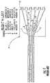
- FIG. 1illustrates a conventional module “A” having six fiber pairs matched as follows: 1 – 2 ; 3 – 4 ; 5 – 6 ; 7 – 8 ; 9 – 10 ; and 11 – 12 . All of the fiber pairs are defined by fibers that are immediately adjacent to one another in the optical fiber ribbon. The fiber pairs are routed to multi-fiber or single-fiber connectors 13 within module A, fiber 1 is immediately adjacent to fiber 2 , fiber 3 next to fiber 4 , and so on. Module A is used in a system utilizing an “A” and “B” type module approach where the fibers in the “B” module are flipped with respect to the fibers in module A to address, or correct for, fiber polarity.
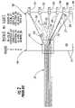
- FIG. 2Another module available from the assignee of the present application is illustrated in FIG. 2 .
- This module 60is the subject of U.S. Pat. No. 6,758,600, the contents of which are incorporated by reference herein.
- a fiber sequencewas devised that eliminated the need for an “A” and “B” module approach and replaced it with a universal wiring module.
- the fibers from the optical fiber ribbon 20are matched up (using the same numbering as in FIG.
- MTP connector 40in that universal module was mated key up to key up to another MTP connector, which suggests a flat polish on the end faces for the key up to key up orientation.
- MTP connectorsare typically connected in a key up to key down orientation, not in a key up to key up orientation.
- the present inventionis directed to a module that substantially obviates one or more of the potential problems and disadvantages in the prior art. Additional features and advantages of the inventions will be set forth in the description that follows, and in part will be apparent from the description, or may be learned by practice of the invention. The objectives and other advantages of the inventions will be realized and attained by the apparatus and process particularly pointed out in the written description and claims, as well as the appended drawings.
- an optical interconnection moduleincludes an enclosure defining at least two walls, an optical interconnection section formed in one of the at least two walls of said enclosure, the optical interconnection section having a first multi-fiber connector with a plurality of optical fibers extending therefrom, the multi-fiber connector having an orientation key and an end face configured to define a predetermined angle, the predetermined angle being positioned relative to the orientation key, an optical connector station formed in the other of the at least two walls of said enclosure, the optical connector station having a plurality of optical fiber connectors, and the first multi-fiber connector and the plurality of optical fiber connectors being optically interconnected by the optical fibers extending from the first multi-fiber connector disposed in said enclosure, at least two optical fibers connected to the multi-fiber connector immediately adjacent one another are connected to optical fiber connectors in the optical connector station that are not immediately adjacent one another.
- the inventionprovides for an optical interconnection module that includes an enclosure defining at least two walls, an optical interconnection section formed in one of the at least two walls of the enclosure, the optical interconnection section having a first multi-fiber connector with a plurality of optical fibers extending therefrom, the multi-fiber connector having an orientation key, an optical connector station formed in the other of the at least two walls of the enclosure, the optical connector station having a plurality of optical fiber connectors, and the first multi-fiber connector and the plurality of optical fiber connectors being optically interconnected by the optical fibers extending from the first multi-fiber connector disposed in the enclosure, at least two optical fibers connected to the multi-fiber connector immediately adjacent one another are connected to optical fiber connectors in the optical connector station that are not immediately adjacent one another, and wherein a connection of the first multi-fiber connector to another multi-fiber connector has a reflective performance of about ⁇ 65 dB.
- an optical interconnection harnessin another aspect of the invention, includes a first end having a multi-fiber connector, the multi-fiber connector having an orientation key and an end face configured to define a predetermined angle, the predetermined angle of the end face being positioned relative to the orientation key on the multi-fiber connector, and a second end, the second end having a plurality of optical fiber connectors positioned relative to one another, and a plurality of optical fibers connecting the multi-fiber connector and the plurality of optical fiber connectors such that at least two optical fibers connected to the multi-fiber connector immediately adjacent to one another are connected to optical fiber connectors in the second end that are not immediately adjacent one another.
- an optical assemblyin another aspect of the invention, includes at least two optical interconnection modules, the modules being optically interconnected by optical paths, the optical paths being established through connectors having orientation keys being positioned on the connectors and each of the connectors having an end face configured to define a predetermined angle, the end face in each of the connectors being positioned in the same position relative to the orientation keys, and the connectors being mated to one another with the orientation keys in an orientation opposite to one another.
- FIG. 1is a schematic view of a conventional module
- FIG. 2is a schematic view of the key up to key up universal wiring module
- FIG. 3is a schematic view of a first optical assembly system according to the present invention.
- FIG. 4is a schematic view of a second optical assembly system according to the present invention.
- the module 102can be an optical networking module for use with an optical fiber ribbon, for example having twelve optical fibers, connected to, for example, an MTP or MPO optical connector 104 .
- the module 102preferably has at least two walls 106 , 108 to define a cavity 110 , but may also have four walls to enclose the cavity 110 .
- the module 102preferably has an optical connection section 112 in one of the walls that includes the optical connector 104 .
- the preferred, exemplary connectoris an MTP or MPO connector 104 .
- Connectors 104are epoxy and polish compatible multi-fiber connectors, for example, a part of Corning Cable Systems' LANScape® solution set.
- the exemplary epoxy and polish connector 104is a twelve-fiber connector achieving very high density in a small space.
- the connector 104may have a front face that is configured with an angled end face.
- the end faceis typically polished or otherwise configured to about an 8° angle.
- the angled end facewhen mated with a connector with the same angled end face, polished with the same orientation with respect to an orientation key, allows for better reflective performance of the connector pair.
- the reflective performance of two mated, angled connectorsis usually about ⁇ 65 dB, which may be a requirement for an installed system.
- the connector 104has optical fibers 114 passing therethrough and extending out the back of the connector, usually in a ribbonized format.
- the optical fibers 114are secured in the connector 104 and the front face of the connector 104 is polished with the optical fibers flush with the front face of the connector.
- the optical fibers 114are then routed from the connector 104 through the module 102 to a break-out section 116 that holds a plurality of connectors 118 .
- the connectors 118are preferably single fiber LC connectors that are duplexed together. However, any appropriate connector may be used and they may or may not be duplexed together at the break-out section 116 .
- the connector 104is illustrated in FIG. 3 with the orientation key 120 in a key down orientation, while the connector 122 to which it connects, shown attached to a non-standard optical fiber trunk line 124 , as will be described in greater detail below, is oriented with the orientation key 126 in a key up orientation. It should also be noted that the connector 104 has guide pins 128 installed so it can mate with the connector 122 . When both of the connectors 104 and 122 have angled end faces (typically about an 8° angle), the reflective performance is better than if the end faces of the connectors 104 , 122 were flat (about a 0° angle). However, the present invention is not dependent on the exact angle of the end face of the connectors, and any combination of mated end faces having the same angle are within the merits of present invention.
- the inventionmay also be embodied in a harness 130 , which is schematically shown in FIG. 3 .
- the harnessas is known in the art, is a flexible assembly of connectors and optical fibers.
- a preferred embodiment of a harness 130includes a multi-fiber connector 132 , and optical fibers 134 extending from the connector 132 to a plurality of fiber optic connectors 136 .
- the optical fibers 134typically have a covering or sleeve to protect them during handling and routing that is omitted for clarity.
- the fiber optic connectors 136may or may not be all connected to one another, but pairs of connectors (one for transmitting and one for receiving a signal) are usually held together by a holder.
- the connector 132also has guide pins 138 to assist in alignment of the connector 132 with the connector 140 in the representative trunk line 124 .
- the mating of the connectors 132 , 140is also done in a key up to key down orientation, with the key 142 on connector 132 facing down and the key 144 on connector 140 facing up.
- the connectors 104 and 122 , as well as connectors 132 and 140are preferably connected to each other using standard MTP adapter sleeves. There is no need, as with the prior art system, to have a specialized adapter sleeve to allow for a key up to key up orientation of the connectors. Thus, the connections may be made with the standard equipment.
- the routing of the optical fibers in the module 102 and the harness 130are routed in the same way.
- the blue fiber (fiber 1 )is on the left (following the fiber into the MTP connector 104 —which is standard for MTP connectors) and is routed from the first position or first fiber optic connector ( 1 ) in break-out section 116 into that first position in the connector 104 .
- the second fiber from the second connector ( 2 ) in break-out section 116is then routed to the twelfth position in the connector 104 .
- the third fiber from the third connector ( 3 )is then routed into the second position in the connector 104 and the fourth fiber from the fourth connector ( 4 ) is routed into the eleventh position in the connector 104 .
- This processcontinues through all twelve fibers.
- the optical fibers in the trunk line 124are arranged straight through from the connector 122 to the connector 140 , i.e. without twist. It should be noted that the fibers are inserted in the standard order into connector 140 based on the key up orientation of the connector, but they are considered to be reversed in connector 122 , where the blue fiber (fiber 1 ) is in position 12 and the aqua fiber (fiber 12 ) is in position 1 . While a harness 130 is illustrated at one end of assembly 100 and a module 102 ′ on the other end of assembly 100 , the ends of the assembly 100 may both be harnesses or both be modules and still fall within the scope of the present inventions.
- the fiber from the first connector 118 in break-out section 116is routed through connectors 104 and 122 to the bottom fiber (fiber 12 ) in the trunk 124 , through connectors 140 and 132 to the second connector of the connectors 136 .
- the optical fiber from the second of the connectors 118 in break-out section 116is routed through connectors 104 , 122 to the top fiber (fiber 1 ) in the trunk 124 , through the connectors 140 , 132 and to the first connector of the connectors 136 . In this manner, the polarity of the fibers is maintained from one end of the system 100 to the other.
- FIG. 4Another embodiment of an optical assembly system according to the present invention is illustrated in FIG. 4 .
- the system 150 of FIG. 4is essentially the same as the system 100 of FIG. 3 , except that an extender trunk 152 has been added between the module 102 ′ and the non-standard trunk line 124 ′.
- the extender trunk 152has optical fibers 162 positioned between two connectors 154 , 156 , which are preferably MTP or MPO connectors as with the other connectors for the system 100 described above.
- the extender trunk 152is configured differently from the trunk line 124 ′ in that rather than having the connectors 154 , 156 being both key up (or key down), the connector 154 has the key 158 in the up position to mate with connector 104 ′ in a key up to key down configuration.
- the other connector 156has the key 160 down to mate with the connector 122 ′ in a key up to key down orientation.
- the optical fibers 162 in extender trunk 152are inserted into the connectors 154 , 156 in the standard format, i.e., the blue fiber (fiber 1 ) is on the right with the key in the up position, as indicated by the reference letter R in FIG. 3 and FIG. 4 .
- the universal wiring module depicted in FIG. 2one of the ends of the extender trunk 152 would have to have a ribbon twist connector since both of the connectors 154 , 156 would have to have their orientation keys 158 , 160 in the key up orientation.
Landscapes
- Physics & Mathematics (AREA)
- General Physics & Mathematics (AREA)
- Optics & Photonics (AREA)
- Mechanical Coupling Of Light Guides (AREA)
Abstract
Description
The present invention relates to optical fiber interconnection modules, for example, to interconnection modules for use in a local area network (LAN).
Conventional fiber optic cables comprise optical fibers that conduct light to transmit voice, video, and data information. An optical ribbon includes a group of optical fibers that are coated with a ribbon common layer, which may be of the ultraviolet (UV) light curable type. Typically, such a ribbon common layer is extruded about a group of individually colored optical fibers that have been arranged in a planar array, and is then irradiated with a UV light source that cures the ribbon common layer. The cured ribbon common layer protects the optical fibers and generally aligns the respective positions of optical fibers in the planar array. Optical fiber ribbons can be connected to multi-fiber connectors, for example, MTP connectors. MTP connectors can be used in LAN applications, for example, data centers and parallel optics interconnects between servers.
The present invention addresses the need for a fiber optic interconnection solution for multi-fiber connectors in the LAN environment. Conventional networking solutions, which utilize a 12-fiber MTP connector assembly, for example, are configured in a point-to-point system. Fiber polarity, i.e., based on a given fiber's transmit-to-receive function in the system, may be addressed by flipping fibers in one end of the assembly just before entering the multi-fiber connector in an epoxy plug, or by providing “A” and “B” type break-out modules where the fiber is flipped in the “B” module and straight in the “A” module.
System problems can occur when the MTP assembly is used in an interconnect construction. Fiber polarity is taken back out of the system when MTP assemblies are interconnected.FIG. 1 illustrates a conventional module “A” having six fiber pairs matched as follows:1–2;3–4;5–6;7–8;9–10; and11–12. All of the fiber pairs are defined by fibers that are immediately adjacent to one another in the optical fiber ribbon. The fiber pairs are routed to multi-fiber or single-fiber connectors 13 within module A,fiber 1 is immediately adjacent tofiber 2,fiber 3 next tofiber 4, and so on. Module A is used in a system utilizing an “A” and “B” type module approach where the fibers in the “B” module are flipped with respect to the fibers in module A to address, or correct for, fiber polarity.
In an effort to reduce implementation confusion, complexity and stocking issues with the “A” and “B” module method, or fiber flipping before entering the connector, another module available from the assignee of the present application is illustrated inFIG. 2 . Thismodule 60 is the subject of U.S. Pat. No. 6,758,600, the contents of which are incorporated by reference herein. In this module, a fiber sequence was devised that eliminated the need for an “A” and “B” module approach and replaced it with a universal wiring module. In the universal wiring module, the fibers from theoptical fiber ribbon 20 are matched up (using the same numbering as inFIG. 1 )1–12;2–11;3–10;4–9;5–8; and6–7 and illustrated inFIG. 2 as21–32,22–31,23–30,24–2925–28, and26–27 going toconnectors 51–56 inbreakout section 50. However, theMTP connector 40 in that universal module was mated key up to key up to another MTP connector, which suggests a flat polish on the end faces for the key up to key up orientation. As noted above, MTP connectors are typically connected in a key up to key down orientation, not in a key up to key up orientation. In an effort to adhere to the convention in MTP connectors of key up to key down mating, a new universal wiring module has been devised. Additionally, the reflectance performance of flat polished ferrules in the connectors is not sufficient for certain applications. Rather, a higher degree of optical performance (measured in dB drop) is required in certain systems.
Accordingly, the present invention is directed to a module that substantially obviates one or more of the potential problems and disadvantages in the prior art. Additional features and advantages of the inventions will be set forth in the description that follows, and in part will be apparent from the description, or may be learned by practice of the invention. The objectives and other advantages of the inventions will be realized and attained by the apparatus and process particularly pointed out in the written description and claims, as well as the appended drawings.
To achieve these and other advantages and in accordance with the purpose of the inventions as embodied and broadly described herein, an optical interconnection module is provided that includes an enclosure defining at least two walls, an optical interconnection section formed in one of the at least two walls of said enclosure, the optical interconnection section having a first multi-fiber connector with a plurality of optical fibers extending therefrom, the multi-fiber connector having an orientation key and an end face configured to define a predetermined angle, the predetermined angle being positioned relative to the orientation key, an optical connector station formed in the other of the at least two walls of said enclosure, the optical connector station having a plurality of optical fiber connectors, and the first multi-fiber connector and the plurality of optical fiber connectors being optically interconnected by the optical fibers extending from the first multi-fiber connector disposed in said enclosure, at least two optical fibers connected to the multi-fiber connector immediately adjacent one another are connected to optical fiber connectors in the optical connector station that are not immediately adjacent one another.
In another aspect, the invention provides for an optical interconnection module that includes an enclosure defining at least two walls, an optical interconnection section formed in one of the at least two walls of the enclosure, the optical interconnection section having a first multi-fiber connector with a plurality of optical fibers extending therefrom, the multi-fiber connector having an orientation key, an optical connector station formed in the other of the at least two walls of the enclosure, the optical connector station having a plurality of optical fiber connectors, and the first multi-fiber connector and the plurality of optical fiber connectors being optically interconnected by the optical fibers extending from the first multi-fiber connector disposed in the enclosure, at least two optical fibers connected to the multi-fiber connector immediately adjacent one another are connected to optical fiber connectors in the optical connector station that are not immediately adjacent one another, and wherein a connection of the first multi-fiber connector to another multi-fiber connector has a reflective performance of about ≦−65 dB.
In another aspect of the invention, an optical interconnection harness includes a first end having a multi-fiber connector, the multi-fiber connector having an orientation key and an end face configured to define a predetermined angle, the predetermined angle of the end face being positioned relative to the orientation key on the multi-fiber connector, and a second end, the second end having a plurality of optical fiber connectors positioned relative to one another, and a plurality of optical fibers connecting the multi-fiber connector and the plurality of optical fiber connectors such that at least two optical fibers connected to the multi-fiber connector immediately adjacent to one another are connected to optical fiber connectors in the second end that are not immediately adjacent one another.
In another aspect of the invention, an optical assembly includes at least two optical interconnection modules, the modules being optically interconnected by optical paths, the optical paths being established through connectors having orientation keys being positioned on the connectors and each of the connectors having an end face configured to define a predetermined angle, the end face in each of the connectors being positioned in the same position relative to the orientation keys, and the connectors being mated to one another with the orientation keys in an orientation opposite to one another.
It is to be understood that the foregoing general description and the following detailed description are exemplary and explanatory and are intended to provide further explanation of the invention as claimed.
The accompanying drawings are included to provide a further understanding of the invention and are incorporated in and constitute a part of the specification. The drawings illustrate several embodiments of the invention and together with the description serve to explain the principles of the invention.
An embodiment of anoptical assembly system 100 that includes anoptical connection module 102 according to the present invention is illustrated inFIG. 3 . Themodule 102 can be an optical networking module for use with an optical fiber ribbon, for example having twelve optical fibers, connected to, for example, an MTP or MPOoptical connector 104. Themodule 102 preferably has at least twowalls cavity 110, but may also have four walls to enclose thecavity 110. Themodule 102 preferably has anoptical connection section 112 in one of the walls that includes theoptical connector 104. The preferred, exemplary connector is an MTP orMPO connector 104.Connectors 104 are epoxy and polish compatible multi-fiber connectors, for example, a part of Corning Cable Systems' LANScape® solution set. The exemplary epoxy andpolish connector 104 is a twelve-fiber connector achieving very high density in a small space. Theconnector 104, as is known in the art, may have a front face that is configured with an angled end face. The end face is typically polished or otherwise configured to about an 8° angle. The angled end face, when mated with a connector with the same angled end face, polished with the same orientation with respect to an orientation key, allows for better reflective performance of the connector pair. The reflective performance of two mated, angled connectors is usually about ≦−65 dB, which may be a requirement for an installed system.
Theconnector 104 hasoptical fibers 114 passing therethrough and extending out the back of the connector, usually in a ribbonized format. Theoptical fibers 114 are secured in theconnector 104 and the front face of theconnector 104 is polished with the optical fibers flush with the front face of the connector. Theoptical fibers 114 are then routed from theconnector 104 through themodule 102 to a break-out section 116 that holds a plurality ofconnectors 118. Theconnectors 118 are preferably single fiber LC connectors that are duplexed together. However, any appropriate connector may be used and they may or may not be duplexed together at the break-outsection 116.
Theconnector 104 is illustrated inFIG. 3 with theorientation key 120 in a key down orientation, while theconnector 122 to which it connects, shown attached to a non-standard opticalfiber trunk line 124, as will be described in greater detail below, is oriented with theorientation key 126 in a key up orientation. It should also be noted that theconnector 104 hasguide pins 128 installed so it can mate with theconnector 122. When both of theconnectors connectors
The invention may also be embodied in aharness 130, which is schematically shown inFIG. 3 . The harness, as is known in the art, is a flexible assembly of connectors and optical fibers. In the present invention, a preferred embodiment of aharness 130 includes amulti-fiber connector 132, andoptical fibers 134 extending from theconnector 132 to a plurality offiber optic connectors 136. Theoptical fibers 134 typically have a covering or sleeve to protect them during handling and routing that is omitted for clarity. Thefiber optic connectors 136 may or may not be all connected to one another, but pairs of connectors (one for transmitting and one for receiving a signal) are usually held together by a holder. Theconnector 132 also has guide pins138 to assist in alignment of theconnector 132 with theconnector 140 in therepresentative trunk line 124. The mating of theconnectors connector 132 facing down and the key144 onconnector 140 facing up. Theconnectors connectors
It should also be noted that the routing of the optical fibers in themodule 102 and theharness 130 are routed in the same way. With reference toFIG. 3 , with the key in the down position, the blue fiber (fiber1) is on the left (following the fiber into theMTP connector 104—which is standard for MTP connectors) and is routed from the first position or first fiber optic connector (1) in break-outsection 116 into that first position in theconnector 104. The second fiber from the second connector (2) in break-outsection 116 is then routed to the twelfth position in theconnector 104. The third fiber from the third connector (3) is then routed into the second position in theconnector 104 and the fourth fiber from the fourth connector (4) is routed into the eleventh position in theconnector 104. This process continues through all twelve fibers. The optical fibers in thetrunk line 124 are arranged straight through from theconnector 122 to theconnector 140, i.e. without twist. It should be noted that the fibers are inserted in the standard order intoconnector 140 based on the key up orientation of the connector, but they are considered to be reversed inconnector 122, where the blue fiber (fiber1) is inposition 12 and the aqua fiber (fiber12) is inposition 1. While aharness 130 is illustrated at one end ofassembly 100 and amodule 102′ on the other end ofassembly 100, the ends of theassembly 100 may both be harnesses or both be modules and still fall within the scope of the present inventions.
Routing the fibers through theassembly 100 will now be described. At the end ofassembly 100 withmodule 102, the fiber from thefirst connector 118 in break-outsection 116 is routed throughconnectors trunk 124, throughconnectors connectors 136. Similarly, the optical fiber from the second of theconnectors 118 in break-outsection 116 is routed throughconnectors trunk 124, through theconnectors connectors 136. In this manner, the polarity of the fibers is maintained from one end of thesystem 100 to the other. This process is followed for the remainder of the optical fibers and the fibers are therefore routed in the universal manner, i.e,1–12;2–11;3–10;4–9;5–8; and6–7.
Another embodiment of an optical assembly system according to the present invention is illustrated inFIG. 4 . Thesystem 150 ofFIG. 4 is essentially the same as thesystem 100 ofFIG. 3 , except that anextender trunk 152 has been added between themodule 102′ and thenon-standard trunk line 124′. Theextender trunk 152 hasoptical fibers 162 positioned between twoconnectors system 100 described above. Theextender trunk 152 is configured differently from thetrunk line 124′ in that rather than having theconnectors connector 154 has the key158 in the up position to mate withconnector 104′ in a key up to key down configuration. Theother connector 156 has the key160 down to mate with theconnector 122′ in a key up to key down orientation. Theoptical fibers 162 inextender trunk 152 are inserted into theconnectors FIG. 3 andFIG. 4 . In the universal wiring module depicted inFIG. 2 , one of the ends of theextender trunk 152 would have to have a ribbon twist connector since both of theconnectors orientation keys
It will be apparent to those skilled in the art that various modifications and variations can be made in the present invention without departing from the spirit or scope of the invention. Thus, it is intended that the present invention cover the modifications and variations of the inventions provided they come within the scope of the appended claims and their equivalents.
Claims (12)
1. An optical interconnection module, comprising:
a) an enclosure comprising wall areas;
b) an optical interconnection section formed in one of the wall areas of said enclosure, said optical interconnection section having a first multi-fiber connector with a plurality of optical fibers extending therefrom, the multi-fiber connector having an orientation key and an end face configured to define a predetermined angle, the predetermined angle being positioned relative to the orientation key;
c) an optical connector station formed in another one of the wall areas of said enclosure, the optical connector station having a plurality of optical fiber connectors associated therewith;
d) the first multi-fiber connector and the plurality of optical fiber connectors being optically interconnected to each other, the optical fibers extending from the first multi-fiber connector disposed in said enclosure, at least two optical fibers connected to the first multi-fiber connector immediately adjacent one another are connected to optical fiber connectors in the optical connector station that are not immediately adjacent one another; and
e) the first multi-fiber connector operable for being connected to a second multi-fiber connector, the second multi-fiber connector having an orientation key and an end face configured to define the same predetermined angle and oriented to the orientation key as the first multi-fiber connector such that when the first and second multi-fiber connectors are connected, the orientation keys are on opposite sides of the connected multi-fiber connectors.
2. The optical interconnection module according toclaim 1 , wherein the predetermined angle is about zero degrees (0°).
3. The optical interconnection module according toclaim 1 , wherein the predetermined angle is about eight degrees (8°).
4. The optical interconnection module according toclaim 1 , wherein the optical fiber connectors are single fiber connectors.
5. The optical interconnection module according toclaim 1 , wherein the end face configured to define a predetermined angle comprises a polished surface area.
6. An optical interconnection module, comprising:
a) an enclosure defining wall areas;
b) an optical interconnection section formed in one of the wall areas of said enclosure, said optical interconnection section having a first multi-fiber connector with a plurality of optical fibers extending therefrom, the multi-fiber connector having an orientation key and an end face configured to define a predetermined angle other than about zero degrees (0°), the predetermined angle being positioned relative to the orientation key;
c) an optical connector station formed in another wall area of said enclosure, the optical connector station having a plurality of optical fiber connectors; and
d) the first multi-fiber connector and the plurality of optical fiber connectors being optically interconnected to each other by the optical fibers extending from the first multi-fiber connector disposed in said enclosure, at least two optical fibers connected to the multi-fiber connector immediately adjacent one another are connected to optical fiber connectors in the optical connector station that are not immediately adjacent one another, and
wherein a connection of the multi-fiber connector to another multi-fiber connector has an optical reflective performance of about ≦−65 dB.
7. The optical interconnection module according toclaim 6 , wherein the multi-fiber connectors are connected in a key up to key down orientation.
8. The optical interconnection module according toclaim 6 , wherein the multi-fiber connectors each have an end face polished to an angle of about eight degrees (8°), the polished end face being positioned relative to the orientation key.
9. An optical interconnection harness comprising;
a first end having a multi-fiber connector, the multi-fiber connector having an orientation key and an end face configured to define a predetermined angle other than about zero degrees (0°), the predetermined angle of the end face being positioned relative to the orientation key on the multi-fiber connector;
a second end having a plurality of optical fiber connectors positioned relative to one another; and
a plurality of optical fibers connecting the multi-fiber connector and the plurality of optical fiber connectors such that at least two optical fibers connected to the multi-fiber connector immediately adjacent one another are connected to optical fiber connectors in the second end that are not immediately adjacent one another.
10. The optical interconnection harness according toclaim 9 , wherein the end face configured to define a predetermined angle comprises a polished surface area.
11. The optical interconnection harness according toclaim 9 , wherein a connection of the multi-fiber connector to another multi-fiber connector has a reflective performance of about ≦−65 dB.
12. The optical interconnection harness according toclaim 9 , wherein the optical fiber connectors are single fiber connectors.
Priority Applications (9)
| Application Number | Priority Date | Filing Date | Title |
|---|---|---|---|
| US11/020,730US7147383B2 (en) | 2004-12-22 | 2004-12-22 | Optical polarity modules and systems |
| AU2005322592AAU2005322592B2 (en) | 2004-12-22 | 2005-04-29 | Optical polarity modules and systems |
| MX2007007657AMX2007007657A (en) | 2004-12-22 | 2005-04-29 | Optical polarity modules and systems. |
| JP2007548178AJP2008525845A (en) | 2004-12-22 | 2005-04-29 | Optical polarity module and system |
| CNA2005800459651ACN101107551A (en) | 2004-12-22 | 2005-04-29 | Optical polarity module and system |
| PCT/US2005/014845WO2006071254A1 (en) | 2004-12-22 | 2005-04-29 | Optical polarity modules and systems |
| EP05758479AEP1834199A1 (en) | 2004-12-22 | 2005-04-29 | Optical polarity modules and systems |
| CA002592416ACA2592416A1 (en) | 2004-12-22 | 2005-04-29 | Optical polarity modules and systems |
| CN201310115443.0ACN103226222A (en) | 2004-12-22 | 2005-04-29 | Optical polarity modules and systems |
Applications Claiming Priority (1)
| Application Number | Priority Date | Filing Date | Title |
|---|---|---|---|
| US11/020,730US7147383B2 (en) | 2004-12-22 | 2004-12-22 | Optical polarity modules and systems |
Publications (2)
| Publication Number | Publication Date |
|---|---|
| US20060133736A1 US20060133736A1 (en) | 2006-06-22 |
| US7147383B2true US7147383B2 (en) | 2006-12-12 |
Family
ID=35005770
Family Applications (1)
| Application Number | Title | Priority Date | Filing Date |
|---|---|---|---|
| US11/020,730Expired - LifetimeUS7147383B2 (en) | 2004-12-22 | 2004-12-22 | Optical polarity modules and systems |
Country Status (8)
| Country | Link |
|---|---|
| US (1) | US7147383B2 (en) |
| EP (1) | EP1834199A1 (en) |
| JP (1) | JP2008525845A (en) |
| CN (2) | CN101107551A (en) |
| AU (1) | AU2005322592B2 (en) |
| CA (1) | CA2592416A1 (en) |
| MX (1) | MX2007007657A (en) |
| WO (1) | WO2006071254A1 (en) |
Cited By (57)
| Publication number | Priority date | Publication date | Assignee | Title |
|---|---|---|---|---|
| US20090180737A1 (en)* | 2008-01-11 | 2009-07-16 | Burnham William R | Optical fiber interconnection devices and systems using same |
| US20100034503A1 (en)* | 2003-09-22 | 2010-02-11 | Luc Milette | Keyed fibre optic connector |
| US20100092129A1 (en)* | 2008-10-14 | 2010-04-15 | Conner Mark E | Fiber Optic Network Architecture Having Optical Connection Terminals in Series Arrangement |
| US20100098428A1 (en)* | 2008-10-17 | 2010-04-22 | Barnes Ray S | Optical interconnection modules for hybrid electrical-optical networks |
| US20100220961A1 (en)* | 2009-02-27 | 2010-09-02 | De Jong Michael | Duplex Fiber Optic Assemblies Suitable for Polarity Reversal and Methods Therefor |
| US20100303408A1 (en)* | 2009-05-27 | 2010-12-02 | Conner Mark E | Port Mapping for Series Connected Fiber Optic Terminals |
| US20110217016A1 (en)* | 2008-02-01 | 2011-09-08 | Mullsteff David M | Fiber optic communication system |
| US20120251064A1 (en)* | 2011-03-29 | 2012-10-04 | Thomas Crain | Zero u fiber distributor, mpo fanout |
| US20130308916A1 (en)* | 2012-05-16 | 2013-11-21 | Scott Eaker Buff | High-density port tap fiber optic modules, and related systems and methods for monitoring optical networks |
| US20140140660A1 (en)* | 2012-11-19 | 2014-05-22 | Scott Eaker Buff | Polarity scheme for parallel-optics data transmission |
| US20140270654A1 (en)* | 2013-03-18 | 2014-09-18 | Hon Hai Precision Industry Co., Ltd. | Optical fiber assembly with replaceable connecting element |
| DE102013102853A1 (en)* | 2013-03-20 | 2014-09-25 | Reichle + De-Massari Ag | connecting device |
| US8879881B2 (en) | 2010-04-30 | 2014-11-04 | Corning Cable Systems Llc | Rotatable routing guide and assembly |
| US8913866B2 (en) | 2010-03-26 | 2014-12-16 | Corning Cable Systems Llc | Movable adapter panel |
| US8953924B2 (en) | 2011-09-02 | 2015-02-10 | Corning Cable Systems Llc | Removable strain relief brackets for securing fiber optic cables and/or optical fibers to fiber optic equipment, and related assemblies and methods |
| US8965168B2 (en) | 2010-04-30 | 2015-02-24 | Corning Cable Systems Llc | Fiber management devices for fiber optic housings, and related components and methods |
| US8985862B2 (en) | 2013-02-28 | 2015-03-24 | Corning Cable Systems Llc | High-density multi-fiber adapter housings |
| US8989547B2 (en) | 2011-06-30 | 2015-03-24 | Corning Cable Systems Llc | Fiber optic equipment assemblies employing non-U-width-sized housings and related methods |
| US8995812B2 (en) | 2012-10-26 | 2015-03-31 | Ccs Technology, Inc. | Fiber optic management unit and fiber optic distribution device |
| US8992099B2 (en) | 2010-02-04 | 2015-03-31 | Corning Cable Systems Llc | Optical interface cards, assemblies, and related methods, suited for installation and use in antenna system equipment |
| US9008485B2 (en) | 2011-05-09 | 2015-04-14 | Corning Cable Systems Llc | Attachment mechanisms employed to attach a rear housing section to a fiber optic housing, and related assemblies and methods |
| US9020320B2 (en) | 2008-08-29 | 2015-04-28 | Corning Cable Systems Llc | High density and bandwidth fiber optic apparatuses and related equipment and methods |
| US9022814B2 (en) | 2010-04-16 | 2015-05-05 | Ccs Technology, Inc. | Sealing and strain relief device for data cables |
| US9042702B2 (en) | 2012-09-18 | 2015-05-26 | Corning Cable Systems Llc | Platforms and systems for fiber optic cable attachment |
| US9038832B2 (en) | 2011-11-30 | 2015-05-26 | Corning Cable Systems Llc | Adapter panel support assembly |
| US9057863B2 (en) | 2012-07-25 | 2015-06-16 | Corning Cable Systems Llc | Polarity scheme for parallel-optics data transmission |
| US9075217B2 (en) | 2010-04-30 | 2015-07-07 | Corning Cable Systems Llc | Apparatuses and related components and methods for expanding capacity of fiber optic housings |
| US9097873B2 (en) | 2010-04-14 | 2015-08-04 | Corning Cable Systems Llc | Port mapping in fiber optic network devices |
| US9097874B2 (en) | 2012-07-25 | 2015-08-04 | Corning Optical Communications LLC | Polarity configurations for parallel optics data transmission, and related apparatuses, components, systems, and methods |
| US9213161B2 (en) | 2010-11-05 | 2015-12-15 | Corning Cable Systems Llc | Fiber body holder and strain relief device |
| US9229175B2 (en) | 2009-06-17 | 2016-01-05 | Corning Cable Systems Llc | Optical interconnection assemblies and systems for high-speed data-rate optical transport systems |
| US9250409B2 (en) | 2012-07-02 | 2016-02-02 | Corning Cable Systems Llc | Fiber-optic-module trays and drawers for fiber-optic equipment |
| US9261654B2 (en) | 2009-10-13 | 2016-02-16 | Leviton Manufacturing Co., Inc. | Fiber optic adapter plates with integrated fiber optic adapters |
| US9279951B2 (en) | 2010-10-27 | 2016-03-08 | Corning Cable Systems Llc | Fiber optic module for limited space applications having a partially sealed module sub-assembly |
| US9316803B2 (en) | 2013-03-15 | 2016-04-19 | Leviton Manufacturing Co., Inc. | Efficient fiber usage within pre-terminated fiber devices |
| US9354418B2 (en) | 2010-01-19 | 2016-05-31 | Commscope, Inc. Of North Carolina | Optical fiber array connectivity system for multiple row trunk cables and terminals |
| US9519118B2 (en) | 2010-04-30 | 2016-12-13 | Corning Optical Communications LLC | Removable fiber management sections for fiber optic housings, and related components and methods |
| US9645317B2 (en) | 2011-02-02 | 2017-05-09 | Corning Optical Communications LLC | Optical backplane extension modules, and related assemblies suitable for establishing optical connections to information processing modules disposed in equipment racks |
| US9651755B2 (en) | 2014-09-30 | 2017-05-16 | Panduit Corp. | Fiber optic interconnect systems and methods |
| US9690065B2 (en) | 2014-09-12 | 2017-06-27 | Panduit Corp. | High density fiber enclosure and method |
| US9829651B2 (en) | 2014-05-16 | 2017-11-28 | Corning Optical Communications LLC | Systems and methods for optically connecting fiber arrays with paired transmit and receive fibers |
| US9885845B2 (en)* | 2015-01-15 | 2018-02-06 | Commscope, Inc. Of North Carolina | Module and assembly for fiber optic interconnections |
| US9958620B2 (en) | 2015-12-03 | 2018-05-01 | Sei Optifrontier Co., Ltd. | Optical fiber with connector |
| US10094996B2 (en) | 2008-08-29 | 2018-10-09 | Corning Optical Communications, Llc | Independently translatable modules and fiber optic equipment trays in fiber optic equipment |
| US10215944B2 (en) | 2016-06-30 | 2019-02-26 | Panduit Corp. | Modular fiber optic tray |
| US20190170957A1 (en)* | 2017-12-05 | 2019-06-06 | Corning Research & Development Corporation | Traceable fiber optic cable assembly with indication of polarity |
| US10451803B2 (en) | 2014-05-16 | 2019-10-22 | Corning Optical Communications LLC | Multimode optical transmission system employing modal-conditioning fiber |
| US10534135B2 (en) | 2015-07-17 | 2020-01-14 | Corning Optical Communications LLC | Systems and methods for tracing cables and cables for such systems and methods |
| US10539747B2 (en) | 2017-12-05 | 2020-01-21 | Corning Research & Development Corporation | Bend induced light scattering fiber and cable assemblies and method of making |
| US10541754B2 (en) | 2014-05-09 | 2020-01-21 | Sumitomo Electric Lightwave Corp. | Reduced fiber count networks, devices, and related methods |
| US10545298B2 (en) | 2016-12-21 | 2020-01-28 | Corning Research & Development Corporation | Traceable fiber optic cable assembly with illumination structure and tracing optical fibers for carrying light received from a light launch device |
| US10816734B2 (en) | 2014-05-16 | 2020-10-27 | Corning Optical Communications LLC | Multimode optical transmission system employing modal-conditioning fiber |
| EP3796057A1 (en) | 2019-09-23 | 2021-03-24 | OFS Fitel, LLC (a Delaware Limited Liability Company) | Routing of multicore optical fibers in data networks |
| WO2021258038A1 (en) | 2020-06-19 | 2021-12-23 | US Conec, Ltd | System and method for guaranteeing correct polarity of fiber optic connector |
| US11294136B2 (en) | 2008-08-29 | 2022-04-05 | Corning Optical Communications LLC | High density and bandwidth fiber optic apparatuses and related equipment and methods |
| US20230028161A1 (en)* | 2020-02-18 | 2023-01-26 | Sumitomo Electric Industries, Ltd. | Fiber connection structure with optical connector, and module |
| US11740410B2 (en) | 2019-09-23 | 2023-08-29 | Ofs Fitel, Llc | Routing of multicore optical fibers in data networks |
Families Citing this family (8)
| Publication number | Priority date | Publication date | Assignee | Title |
|---|---|---|---|---|
| US8797150B2 (en)* | 2006-08-31 | 2014-08-05 | Asoka Usa Corporation | Method and system for power line networking for industrial process control applications |
| CN102460255A (en)* | 2009-06-17 | 2012-05-16 | 康宁光缆系统有限责任公司 | Optical interconnections for high-speed data-rate transport systems |
| US8009959B2 (en)* | 2009-06-17 | 2011-08-30 | Corning Cable Systems Llc | Optical interconnection methods for high-speed data-rate optical transport systems |
| US8485737B2 (en)* | 2009-10-29 | 2013-07-16 | Commscope, Inc. Of North Carolina | Optical fiber array connectivity system for multiple transceivers and/or multiple trunk cables |
| US8406587B2 (en) | 2010-05-06 | 2013-03-26 | Commscope, Inc. Of North Carolina | Quad small form factor pluggable (QSFP) adapter module |
| JP5707905B2 (en) | 2010-12-03 | 2015-04-30 | 住友電気工業株式会社 | Optical module and optical system |
| EP3368929A4 (en)* | 2015-10-27 | 2019-06-26 | CommScope, Inc. of North Carolina | Fiber optic lane changers for use with fiber optic cables having unused optical fibers and related methods |
| CA3035745A1 (en)* | 2016-09-02 | 2018-03-08 | Commscope Technologies Llc | Optical fiber connectivity system including modules and interconnection cables |
Citations (2)
| Publication number | Priority date | Publication date | Assignee | Title |
|---|---|---|---|---|
| US6758600B2 (en)* | 2002-09-27 | 2004-07-06 | Corning Cable Systems Llc | Optical polarity modules and systems |
| US20050207709A1 (en)* | 2004-03-22 | 2005-09-22 | Del Grosso Steven C | Optical polarity modules and systems |
Family Cites Families (3)
| Publication number | Priority date | Publication date | Assignee | Title |
|---|---|---|---|---|
| JP2001515597A (en)* | 1997-03-14 | 2001-09-18 | ローズマウント アナリティカル インコーポレイテッド | Improved Rayleigh backscatter control apparatus and method |
| CA2302068A1 (en)* | 1999-04-01 | 2000-10-01 | Michael De Jong | Fiber optic connector sleeve |
| JP3730871B2 (en)* | 2001-03-01 | 2006-01-05 | 日本電気株式会社 | Tape optical fiber cord with optical fiber array |
- 2004
- 2004-12-22USUS11/020,730patent/US7147383B2/ennot_activeExpired - Lifetime
- 2005
- 2005-04-29CNCNA2005800459651Apatent/CN101107551A/enactivePending
- 2005-04-29AUAU2005322592Apatent/AU2005322592B2/ennot_activeCeased
- 2005-04-29WOPCT/US2005/014845patent/WO2006071254A1/enactiveApplication Filing
- 2005-04-29EPEP05758479Apatent/EP1834199A1/ennot_activeWithdrawn
- 2005-04-29CNCN201310115443.0Apatent/CN103226222A/enactivePending
- 2005-04-29CACA002592416Apatent/CA2592416A1/ennot_activeAbandoned
- 2005-04-29MXMX2007007657Apatent/MX2007007657A/enactiveIP Right Grant
- 2005-04-29JPJP2007548178Apatent/JP2008525845A/enactivePending
Patent Citations (4)
| Publication number | Priority date | Publication date | Assignee | Title |
|---|---|---|---|---|
| US6758600B2 (en)* | 2002-09-27 | 2004-07-06 | Corning Cable Systems Llc | Optical polarity modules and systems |
| US20040184741A1 (en) | 2002-09-27 | 2004-09-23 | Del Grosso Steven C. | Optical polarity modules and systems |
| US6869227B2 (en)* | 2002-09-27 | 2005-03-22 | Corning Cable Systems Llc | Optical polarity modules and systems |
| US20050207709A1 (en)* | 2004-03-22 | 2005-09-22 | Del Grosso Steven C | Optical polarity modules and systems |
Cited By (99)
| Publication number | Priority date | Publication date | Assignee | Title |
|---|---|---|---|---|
| US20100034503A1 (en)* | 2003-09-22 | 2010-02-11 | Luc Milette | Keyed fibre optic connector |
| US7689079B2 (en)* | 2008-01-11 | 2010-03-30 | Corning Cable Systems Llc | Optical fiber interconnection devices and systems using same |
| US20090180737A1 (en)* | 2008-01-11 | 2009-07-16 | Burnham William R | Optical fiber interconnection devices and systems using same |
| US20110217016A1 (en)* | 2008-02-01 | 2011-09-08 | Mullsteff David M | Fiber optic communication system |
| US11092767B2 (en) | 2008-08-29 | 2021-08-17 | Corning Optical Communications LLC | High density and bandwidth fiber optic apparatuses and related equipment and methods |
| US10222570B2 (en) | 2008-08-29 | 2019-03-05 | Corning Optical Communications LLC | Independently translatable modules and fiber optic equipment trays in fiber optic equipment |
| US12072545B2 (en) | 2008-08-29 | 2024-08-27 | Corning Optical Communications LLC | High density and bandwidth fiber optic apparatuses and related equipment and methods |
| US11754796B2 (en) | 2008-08-29 | 2023-09-12 | Corning Optical Communications LLC | Independently translatable modules and fiber optic equipment trays in fiber optic equipment |
| US11609396B2 (en) | 2008-08-29 | 2023-03-21 | Corning Optical Communications LLC | High density and bandwidth fiber optic apparatuses and related equipment and methods |
| US10564378B2 (en) | 2008-08-29 | 2020-02-18 | Corning Optical Communications LLC | High density and bandwidth fiber optic apparatuses and related equipment and methods |
| US10606014B2 (en) | 2008-08-29 | 2020-03-31 | Corning Optical Communications LLC | Independently translatable modules and fiber optic equipment trays in fiber optic equipment |
| US10459184B2 (en) | 2008-08-29 | 2019-10-29 | Corning Optical Communications LLC | High density and bandwidth fiber optic apparatuses and related equipment and methods |
| US10444456B2 (en) | 2008-08-29 | 2019-10-15 | Corning Optical Communications LLC | High density and bandwidth fiber optic apparatuses and related equipment and methods |
| US10422971B2 (en) | 2008-08-29 | 2019-09-24 | Corning Optical Communicatinos LLC | High density and bandwidth fiber optic apparatuses and related equipment and methods |
| US10416405B2 (en) | 2008-08-29 | 2019-09-17 | Corning Optical Communications LLC | Independently translatable modules and fiber optic equipment trays in fiber optic equipment |
| US10852499B2 (en) | 2008-08-29 | 2020-12-01 | Corning Optical Communications LLC | High density and bandwidth fiber optic apparatuses and related equipment and methods |
| US9910236B2 (en) | 2008-08-29 | 2018-03-06 | Corning Optical Communications LLC | High density and bandwidth fiber optic apparatuses and related equipment and methods |
| US11086089B2 (en) | 2008-08-29 | 2021-08-10 | Corning Optical Communications LLC | High density and bandwidth fiber optic apparatuses and related equipment and methods |
| US9020320B2 (en) | 2008-08-29 | 2015-04-28 | Corning Cable Systems Llc | High density and bandwidth fiber optic apparatuses and related equipment and methods |
| US11294135B2 (en) | 2008-08-29 | 2022-04-05 | Corning Optical Communications LLC | High density and bandwidth fiber optic apparatuses and related equipment and methods |
| US11294136B2 (en) | 2008-08-29 | 2022-04-05 | Corning Optical Communications LLC | High density and bandwidth fiber optic apparatuses and related equipment and methods |
| US10126514B2 (en) | 2008-08-29 | 2018-11-13 | Corning Optical Communications, Llc | Independently translatable modules and fiber optic equipment trays in fiber optic equipment |
| US10120153B2 (en) | 2008-08-29 | 2018-11-06 | Corning Optical Communications, Llc | Independently translatable modules and fiber optic equipment trays in fiber optic equipment |
| US10094996B2 (en) | 2008-08-29 | 2018-10-09 | Corning Optical Communications, Llc | Independently translatable modules and fiber optic equipment trays in fiber optic equipment |
| US20100092129A1 (en)* | 2008-10-14 | 2010-04-15 | Conner Mark E | Fiber Optic Network Architecture Having Optical Connection Terminals in Series Arrangement |
| US9207421B2 (en) | 2008-10-14 | 2015-12-08 | Corning Cable Systems Llc | Fiber optic network architecture having optical connection terminals in series arrangement |
| US8873967B2 (en)* | 2008-10-17 | 2014-10-28 | Corning Cable Systems Llc | Optical interconnection modules for hybrid electrical-optical networks |
| US20100098428A1 (en)* | 2008-10-17 | 2010-04-22 | Barnes Ray S | Optical interconnection modules for hybrid electrical-optical networks |
| US20100220961A1 (en)* | 2009-02-27 | 2010-09-02 | De Jong Michael | Duplex Fiber Optic Assemblies Suitable for Polarity Reversal and Methods Therefor |
| US8152385B2 (en) | 2009-02-27 | 2012-04-10 | Corning Cable Systems Llc | Duplex fiber optic assemblies suitable for polarity reversal and methods therefor |
| US20100303408A1 (en)* | 2009-05-27 | 2010-12-02 | Conner Mark E | Port Mapping for Series Connected Fiber Optic Terminals |
| US9482840B2 (en) | 2009-05-27 | 2016-11-01 | Corning Cable Systems Llc | Port mapping for series connected fiber optic terminals |
| US9229175B2 (en) | 2009-06-17 | 2016-01-05 | Corning Cable Systems Llc | Optical interconnection assemblies and systems for high-speed data-rate optical transport systems |
| US9261654B2 (en) | 2009-10-13 | 2016-02-16 | Leviton Manufacturing Co., Inc. | Fiber optic adapter plates with integrated fiber optic adapters |
| US9354418B2 (en) | 2010-01-19 | 2016-05-31 | Commscope, Inc. Of North Carolina | Optical fiber array connectivity system for multiple row trunk cables and terminals |
| US8992099B2 (en) | 2010-02-04 | 2015-03-31 | Corning Cable Systems Llc | Optical interface cards, assemblies, and related methods, suited for installation and use in antenna system equipment |
| US8913866B2 (en) | 2010-03-26 | 2014-12-16 | Corning Cable Systems Llc | Movable adapter panel |
| US9097873B2 (en) | 2010-04-14 | 2015-08-04 | Corning Cable Systems Llc | Port mapping in fiber optic network devices |
| US9022814B2 (en) | 2010-04-16 | 2015-05-05 | Ccs Technology, Inc. | Sealing and strain relief device for data cables |
| US8879881B2 (en) | 2010-04-30 | 2014-11-04 | Corning Cable Systems Llc | Rotatable routing guide and assembly |
| US9519118B2 (en) | 2010-04-30 | 2016-12-13 | Corning Optical Communications LLC | Removable fiber management sections for fiber optic housings, and related components and methods |
| US9075217B2 (en) | 2010-04-30 | 2015-07-07 | Corning Cable Systems Llc | Apparatuses and related components and methods for expanding capacity of fiber optic housings |
| US8965168B2 (en) | 2010-04-30 | 2015-02-24 | Corning Cable Systems Llc | Fiber management devices for fiber optic housings, and related components and methods |
| US9279951B2 (en) | 2010-10-27 | 2016-03-08 | Corning Cable Systems Llc | Fiber optic module for limited space applications having a partially sealed module sub-assembly |
| US9213161B2 (en) | 2010-11-05 | 2015-12-15 | Corning Cable Systems Llc | Fiber body holder and strain relief device |
| US10481335B2 (en) | 2011-02-02 | 2019-11-19 | Corning Optical Communications, Llc | Dense shuttered fiber optic connectors and assemblies suitable for establishing optical connections for optical backplanes in equipment racks |
| US9645317B2 (en) | 2011-02-02 | 2017-05-09 | Corning Optical Communications LLC | Optical backplane extension modules, and related assemblies suitable for establishing optical connections to information processing modules disposed in equipment racks |
| US20120251064A1 (en)* | 2011-03-29 | 2012-10-04 | Thomas Crain | Zero u fiber distributor, mpo fanout |
| US8867883B2 (en)* | 2011-03-29 | 2014-10-21 | Commscope, Inc. Of North Carolina | Zero U fiber distributor, MPO fanout |
| US9008485B2 (en) | 2011-05-09 | 2015-04-14 | Corning Cable Systems Llc | Attachment mechanisms employed to attach a rear housing section to a fiber optic housing, and related assemblies and methods |
| US8989547B2 (en) | 2011-06-30 | 2015-03-24 | Corning Cable Systems Llc | Fiber optic equipment assemblies employing non-U-width-sized housings and related methods |
| US8953924B2 (en) | 2011-09-02 | 2015-02-10 | Corning Cable Systems Llc | Removable strain relief brackets for securing fiber optic cables and/or optical fibers to fiber optic equipment, and related assemblies and methods |
| US9038832B2 (en) | 2011-11-30 | 2015-05-26 | Corning Cable Systems Llc | Adapter panel support assembly |
| US20130308915A1 (en)* | 2012-05-16 | 2013-11-21 | Scott Eaker Buff | Port tap fiber optic modules, and related systems and methods for monitoring optical networks |
| US20130308916A1 (en)* | 2012-05-16 | 2013-11-21 | Scott Eaker Buff | High-density port tap fiber optic modules, and related systems and methods for monitoring optical networks |
| US9250409B2 (en) | 2012-07-02 | 2016-02-02 | Corning Cable Systems Llc | Fiber-optic-module trays and drawers for fiber-optic equipment |
| US9057863B2 (en) | 2012-07-25 | 2015-06-16 | Corning Cable Systems Llc | Polarity scheme for parallel-optics data transmission |
| US9097874B2 (en) | 2012-07-25 | 2015-08-04 | Corning Optical Communications LLC | Polarity configurations for parallel optics data transmission, and related apparatuses, components, systems, and methods |
| US9042702B2 (en) | 2012-09-18 | 2015-05-26 | Corning Cable Systems Llc | Platforms and systems for fiber optic cable attachment |
| US8995812B2 (en) | 2012-10-26 | 2015-03-31 | Ccs Technology, Inc. | Fiber optic management unit and fiber optic distribution device |
| US20140140660A1 (en)* | 2012-11-19 | 2014-05-22 | Scott Eaker Buff | Polarity scheme for parallel-optics data transmission |
| US8985862B2 (en) | 2013-02-28 | 2015-03-24 | Corning Cable Systems Llc | High-density multi-fiber adapter housings |
| US9316803B2 (en) | 2013-03-15 | 2016-04-19 | Leviton Manufacturing Co., Inc. | Efficient fiber usage within pre-terminated fiber devices |
| US20140270654A1 (en)* | 2013-03-18 | 2014-09-18 | Hon Hai Precision Industry Co., Ltd. | Optical fiber assembly with replaceable connecting element |
| DE102013102853A1 (en)* | 2013-03-20 | 2014-09-25 | Reichle + De-Massari Ag | connecting device |
| US10541754B2 (en) | 2014-05-09 | 2020-01-21 | Sumitomo Electric Lightwave Corp. | Reduced fiber count networks, devices, and related methods |
| US10215933B2 (en) | 2014-05-16 | 2019-02-26 | Corning Optical Communications LLC | Systems and methods for optically connecting fiber arrays with paired transmit and receive fibers |
| US10816734B2 (en) | 2014-05-16 | 2020-10-27 | Corning Optical Communications LLC | Multimode optical transmission system employing modal-conditioning fiber |
| US10451803B2 (en) | 2014-05-16 | 2019-10-22 | Corning Optical Communications LLC | Multimode optical transmission system employing modal-conditioning fiber |
| US9829651B2 (en) | 2014-05-16 | 2017-11-28 | Corning Optical Communications LLC | Systems and methods for optically connecting fiber arrays with paired transmit and receive fibers |
| US9864158B2 (en) | 2014-09-12 | 2018-01-09 | Panduit Corp. | High density fiber enclosure and method |
| US10317637B2 (en) | 2014-09-12 | 2019-06-11 | Panduit Corp. | High density fiber enclosure and method |
| US12228782B2 (en) | 2014-09-12 | 2025-02-18 | Panduit Corp. | High density fiber enclosure and method |
| US10606013B2 (en) | 2014-09-12 | 2020-03-31 | Panduit Corp. | High density fiber enclosure and method |
| US11105995B2 (en) | 2014-09-12 | 2021-08-31 | Panduit Corp. | High density fiber enclosure and method |
| US10268013B2 (en) | 2014-09-12 | 2019-04-23 | Panduit Corp. | High density fiber enclosure and method |
| US10698171B2 (en) | 2014-09-12 | 2020-06-30 | Panduit Corp. | High density fiber enclosure and method |
| US9690065B2 (en) | 2014-09-12 | 2017-06-27 | Panduit Corp. | High density fiber enclosure and method |
| US10768385B2 (en) | 2014-09-12 | 2020-09-08 | Panduit Corp. | High density fiber enclosure and method |
| US11624888B2 (en) | 2014-09-12 | 2023-04-11 | Panduit Corp. | High density fiber enclosure and method |
| US9651755B2 (en) | 2014-09-30 | 2017-05-16 | Panduit Corp. | Fiber optic interconnect systems and methods |
| US9885845B2 (en)* | 2015-01-15 | 2018-02-06 | Commscope, Inc. Of North Carolina | Module and assembly for fiber optic interconnections |
| US10613285B2 (en) | 2015-01-15 | 2020-04-07 | Commscope, Inc. Of North Carolina | Module and assembly for fiber optic interconnections |
| US10534135B2 (en) | 2015-07-17 | 2020-01-14 | Corning Optical Communications LLC | Systems and methods for tracing cables and cables for such systems and methods |
| US9958620B2 (en) | 2015-12-03 | 2018-05-01 | Sei Optifrontier Co., Ltd. | Optical fiber with connector |
| US11709331B2 (en) | 2016-06-30 | 2023-07-25 | Panduit Corp. | Modular fiber optic tray |
| US11372185B2 (en) | 2016-06-30 | 2022-06-28 | Panduit Corp. | Modular fiber optic tray |
| US10215944B2 (en) | 2016-06-30 | 2019-02-26 | Panduit Corp. | Modular fiber optic tray |
| US10725258B2 (en) | 2016-06-30 | 2020-07-28 | Panduit Corp. | Modular fiber optic tray |
| US12105338B2 (en) | 2016-06-30 | 2024-10-01 | Panduit Corp. | Modular fiber optic tray |
| US10545298B2 (en) | 2016-12-21 | 2020-01-28 | Corning Research & Development Corporation | Traceable fiber optic cable assembly with illumination structure and tracing optical fibers for carrying light received from a light launch device |
| US10539747B2 (en) | 2017-12-05 | 2020-01-21 | Corning Research & Development Corporation | Bend induced light scattering fiber and cable assemblies and method of making |
| US10539758B2 (en)* | 2017-12-05 | 2020-01-21 | Corning Research & Development Corporation | Traceable fiber optic cable assembly with indication of polarity |
| US20190170957A1 (en)* | 2017-12-05 | 2019-06-06 | Corning Research & Development Corporation | Traceable fiber optic cable assembly with indication of polarity |
| EP3796057A1 (en) | 2019-09-23 | 2021-03-24 | OFS Fitel, LLC (a Delaware Limited Liability Company) | Routing of multicore optical fibers in data networks |
| US11740410B2 (en) | 2019-09-23 | 2023-08-29 | Ofs Fitel, Llc | Routing of multicore optical fibers in data networks |
| US20230028161A1 (en)* | 2020-02-18 | 2023-01-26 | Sumitomo Electric Industries, Ltd. | Fiber connection structure with optical connector, and module |
| US11953736B2 (en)* | 2020-02-18 | 2024-04-09 | Sumitomo Electric Industries, Ltd. | Fiber connection structure with optical connector, and module |
| WO2021258038A1 (en) | 2020-06-19 | 2021-12-23 | US Conec, Ltd | System and method for guaranteeing correct polarity of fiber optic connector |
Also Published As
| Publication number | Publication date |
|---|---|
| MX2007007657A (en) | 2007-09-05 |
| JP2008525845A (en) | 2008-07-17 |
| AU2005322592A1 (en) | 2006-07-06 |
| US20060133736A1 (en) | 2006-06-22 |
| CA2592416A1 (en) | 2006-07-06 |
| AU2005322592A2 (en) | 2006-07-06 |
| AU2005322592B2 (en) | 2011-06-09 |
| EP1834199A1 (en) | 2007-09-19 |
| CN103226222A (en) | 2013-07-31 |
| CN101107551A (en) | 2008-01-16 |
| WO2006071254A1 (en) | 2006-07-06 |
Similar Documents
| Publication | Publication Date | Title |
|---|---|---|
| US7147383B2 (en) | Optical polarity modules and systems | |
| CA2795809C (en) | Optical polarity modules and systems | |
| US7237966B2 (en) | Polarity maintaining multi-connector optical cable assembly | |
| US9229175B2 (en) | Optical interconnection assemblies and systems for high-speed data-rate optical transport systems | |
| US20050207709A1 (en) | Optical polarity modules and systems | |
| EP2998772A1 (en) | Optical fiber interconnection devices and systems using same | |
| CA2765729C (en) | Optical interconnections for high-speed data-rate transport systems | |
| HK1174692A (en) | Optical polarity modules and systems | |
| HK1171814B (en) | Optical polarity modules and systems | |
| HK1171814A (en) | Optical polarity modules and systems |
Legal Events
| Date | Code | Title | Description |
|---|---|---|---|
| AS | Assignment | Owner name:CORNING CABLE SYSTEMS LLC, NORTH CAROLINA Free format text:ASSIGNMENT OF ASSIGNORS INTEREST;ASSIGNOR:SULLIVAN, KEITH D.;REEL/FRAME:016130/0178 Effective date:20041221 | |
| STCF | Information on status: patent grant | Free format text:PATENTED CASE | |
| FPAY | Fee payment | Year of fee payment:4 | |
| FPAY | Fee payment | Year of fee payment:8 | |
| AS | Assignment | Owner name:CCS TECHNOLOGY, INC., DELAWARE Free format text:ASSIGNMENT OF ASSIGNORS INTEREST;ASSIGNOR:CORNING CABLE SYSTEMS LLC;REEL/FRAME:033601/0127 Effective date:20080508 | |
| AS | Assignment | Owner name:CORNING OPTICAL COMMUNICATIONS LLC, NORTH CAROLINA Free format text:MERGER;ASSIGNORS:CCS TECHNOLOGY, INC.;CORNING OPTICAL COMMUNICATIONS BRANDS, INC.;REEL/FRAME:043601/0427 Effective date:20170630 | |
| MAFP | Maintenance fee payment | Free format text:PAYMENT OF MAINTENANCE FEE, 12TH YEAR, LARGE ENTITY (ORIGINAL EVENT CODE: M1553) Year of fee payment:12 |