US7147163B2 - Adapter unit having an ergonomic grip for a personal digital assistant - Google Patents
Adapter unit having an ergonomic grip for a personal digital assistantDownload PDFInfo
- Publication number
- US7147163B2 US7147163B2US10/790,367US79036704AUS7147163B2US 7147163 B2US7147163 B2US 7147163B2US 79036704 AUS79036704 AUS 79036704AUS 7147163 B2US7147163 B2US 7147163B2
- Authority
- US
- United States
- Prior art keywords
- pda
- adapter
- adapter unit
- sidewalls
- carrier
- Prior art date
- Legal status (The legal status is an assumption and is not a legal conclusion. Google has not performed a legal analysis and makes no representation as to the accuracy of the status listed.)
- Expired - Lifetime, expires
Links
Images


Classifications
- G—PHYSICS
- G06—COMPUTING OR CALCULATING; COUNTING
- G06F—ELECTRIC DIGITAL DATA PROCESSING
- G06F1/00—Details not covered by groups G06F3/00 - G06F13/00 and G06F21/00
- G06F1/16—Constructional details or arrangements
- G06F1/1613—Constructional details or arrangements for portable computers
- G06F1/1632—External expansion units, e.g. docking stations
- G—PHYSICS
- G06—COMPUTING OR CALCULATING; COUNTING
- G06F—ELECTRIC DIGITAL DATA PROCESSING
- G06F2200/00—Indexing scheme relating to G06F1/04 - G06F1/32
- G06F2200/16—Indexing scheme relating to G06F1/16 - G06F1/18
- G06F2200/161—Indexing scheme relating to constructional details of the monitor
- G06F2200/1614—Image rotation following screen orientation, e.g. switching from landscape to portrait mode
Definitions
- This inventionis related generally to an adapter unit for a personal digital assistant. More specifically, this invention relates to an adapter unit that provides additional functionality, and improved ergonomics and increased ruggedness to the personal digital assistant.
- PDAPersonal digital assistants
- PDAsor hand-held computers have limited functions. These devices typically include internal memory for storing application programs and a local database. PDAs also include external connector used during synchronization procedure (“hot-sync”) with an external database located in a local or remote PC. The PDA is typically inserted into a “hot-sync” cradle, which is tethered to a desktop PC. The PC has a second database, which is similar to the local PDA database. During the “sync” operation both databases get updated with any information that was added to either one or the databases since the last synchronization procedure. While these devices can have various application programs running on them, they still have limited functionality. For example, a typical PDA may not have a detachable scanner or a detachable radio or a combination of both.
- the iPAQ PDA manufactured by Compaq Computer Corporationhas an expansion connector for interconnecting with different compatible modules, such as a scanning module.
- the expansion slotdoes not replace the “sync” connector, but is provided in addition to it.
- the iPAQhas to have two separate connectors to accommodate expanded functionality and “sync” operation.
- modulesare able to provide additional functions to the personal digital assistant, such benefits come at a price.
- One of the advantages to the personal digital assistantsis their portability. These units are designed to fit in a user's hand or palm. In many module designs, the depth and/or width of the combination personal digital assistant and module is considerably larger than originally designed by the personal digital assistant manufacturer. The combination of the two devices becomes difficult for a typical user to grasp.
- the PDAincludes volatile memory such as RAM. Information stored in the volatile memory may be lost if the power level of the PDA's battery falls below a certain level.
- the present inventionprovides an adapter unit that can be detachably secured to a hand-held computer, such as a portable digital assistant (“PDA”) computer presently available on the market.
- a hand-held computersuch as a portable digital assistant (“PDA”) computer presently available on the market.
- PDAportable digital assistant
- Examples of such computersare the iPAQ manufactured by Compaq Computer Corporation, the Palm series manufactured by Palm, Inc. and the Visor series manufactured by Handspring Inc.
- the inventionincludes an adapter that adds functionality and ruggedness to a commercially designed device for use in a more industrial environment.
- the adapterhas a PDA connector for interconnecting to the PDA's expansion connector.
- a scanner, battery and radio functionsmay be integrated in the adapter.
- the adaptermay include a card for wireless local area communication such as the Spectrum24® card manufactured by Symbol Technologies Inc., and/or a card for wireless wide area network communication.
- the adaptermay include additional memory for storing data.
- This memorymay include nonvolatile memory such as flash memory for storing drivers that support the functions added by the adapter.
- the memorymay store drivers for a scanner or a wireless local area network.
- the adapterhas a separated expansion connector for accommodating various functional modules.
- the adaptermay also have its own sync connector, allowing it to be directly inserted into the PDA cradle.
- the inventionincludes an adapter unit that connects to PDA via the PDA's expansion connector.
- the adapter unitenhances mechanical ruggedness of the PDA and protects the PDA during drop and vibration.
- the adaptereasily slides on the PDA and may incorporate a retainer clip to lock the adapter and the PDA together. Electronics in the adapter add bar code scanning, imaging capability, additional power, wireless and other PC card support.
- the inventionincludes an adapter unit having a gripping surface that enhances the ergonomics of the adapter and helps prevent the adapter from slipping out of a user's hand.
- the function of one or more of the application buttons on the PDAautomatically changes upon the attachment of a device to the PDA.
- a handleis added to the design, such that a handle supports the adapter, and the PDA/adapter combination is held as a gun-shaped terminal in the hand of a user.
- Batteries, both rechargeable and disposable, chargers and control systemscan be added to the adapter.
- FIG. 1 ais a side view of an embodiment of the adapter of the present invention
- FIG. 1 bis a top perspective view of an embodiment of the adapter of the present invention.
- FIG. 1 cis a back view of an embodiment of the adapter of the present invention.
- FIG. 1 dis a bottom view of an embodiment of the adapter of the present invention.
- FIG. 1 eis a front view of an embodiment of the adapter of the present invention.
- FIG. 1 fis another side view of an embodiment of the adapter of the present invention.
- FIG. 1 gis a bottom perspective view of an embodiment of the adapter of the present invention.
- FIG. 2 ais a side view of an embodiment of the adapter of the present invention illustrating release of the PDA retaining mechanism
- FIG. 2 bis a PDA of the present invention
- FIG. 2 cis an illustration of an embodiment of the adapter of the present invention connected to a PDA
- FIG. 3is a map indicating the relative orientation of the circuits described in FIGS. 3 a – 3 f that comprise an electrical schematic of the adapter of the present invention
- FIG. 3 ashows a portion of an interface connector JH 1 and pin-outs thereof for the adapter interface board
- FIG. 3 bshows the remaining portion of the interface connector JH 1 and pin-outs thereof for the adapter interface board
- FIG. 3 cshows an EEPROM with memory utilized in the adapter interface board
- FIG. 3 dshows inverter circuits used for the INT and RESET lines of the adapter interface board
- FIG. 3 eshows a scanner controller that controls the scanner of the adapter interface board
- FIG. 3 fshows power-down switching transistor and interface connector for the adapter interface board
- FIG. 4 ais a drawing of a primary side view of a circuit board of an embodiment of the adapter of the present invention.
- FIG. 4 bis a drawing of a secondary side view of a circuit board of an embodiment of the adapter of the present invention.
- FIG. 5illustrates an adapter and a hand strap according to the invention
- FIG. 6shows compartment for a rechargeable battery located inside the adapter
- FIG. 7shows an adapter with a handle grip
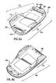
- FIGS. 8 a and 8 bshow a bottom perspective view of another embodiment of the present invention.
- FIG. 9shows an exploded perspective view of the embodiment of the present invention shown in FIGS. 8 a and 8 b;
- FIG. 10shows a top view of the embodiment of the present invention shown in FIGS. 8 a and 8 b;
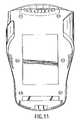
- FIG. 11shows a bottom view of the embodiment of the present invention shown in FIGS. 8 a and 8 b;
- FIG. 12shows a side view of the embodiment of the present invention shown in FIGS. 8 a and 8 b;
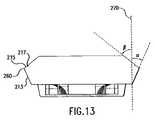
- FIG. 13is a view taken along line A—A of FIG. 12 ;
- FIG. 14shows a flowchart representing a configuration routine for a preferred embodiment of the present invention wherein an adapter is attached to the PDA;
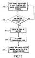
- FIG. 15shows a flowchart representing a configuration routine for another preferred embodiment of the present invention wherein an adapter is attached to the PDA;
- FIG. 16shows a flowchart representing a configuration routine for a preferred embodiment wherein an adapter is removed from the PDA.
- FIG. 17shows a flowchart representing a memory backup system for a preferred embodiment of the present invention.
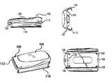
- FIG. 1 arepresents a side view of a preferred embodiment of the adapter 100 of the present invention.
- FIG. 1 bshows the sled adapter from a top perspective view.
- FIG. 1 gis a bottom perspective view of an embodiment of the adapter of the present invention.
- the sled-type adapterincludes a cover 104 and a carrier 106 .
- the carrier 106includes a bottom wall 108 , and two sidewalls 110 extending from bottom wall 108 .
- An interface circuit board and a scanner, a radio, RFID tag reader, global positioning system, telephone, and/or some other module,is housed between the cover 104 and the bottom wall 108 of the adapter.
- FIG. 1 aincludes an integrated radio with a hidden antenna and an interface board that allows connection to the PDA.
- FIG. 1 eis a front view of the adapter.
- FIG. 1 eshows an adapter having an integrated scanner located behind the scanning window 120 .
- Sidewalls 110 of carrier 106are curved in such a way that they surround the PDA on both sides and protect the PDA from side-to-side movement and side impact. Sidewalls 110 prevent the adapter from being pulled off the PDA.
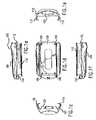
- FIG. 1 cis a back view of the adapter of the present invention. It shows the edges of curved sidewalls 110 and the adapter connector 124 extending from the circuit board.
- FIG. 1 dis a view of the adapter from the bottom, exposing the bottom wall 108 of the carrier from underneath. It shows four fasteners 109 that attach carrier 106 to cover 104 , enclosing the electronics between carrier 106 and cover 104 .
- Carrier 106can be attached to the cover 104 and the electronics by snap-in features, screws or glue. It is preferable to make the adapter as thin and as small as possible in order to make it low profile and enhance its ergonomics.
- the height of the sidewallsis dictated by the height of the PDA to which the adapter attaches. In other designs the sidewalls may only partially cover the sides of the PDA.
- the sidewallsmay be replaced by a pair of rails that mate with the corresponding guides on the PDA.
- the sidewallsare eliminated, the overall ruggedness of the adapter/PDA-combined device is reduced.
- FIGS. 1 f–gare additional views of the adapter when it is placed upside down.
- Adapter connector 124restricts movement of the PDA in one direction along the length of adapter 100 .
- a retainer clip 112is provided as part of adapter 100 .
- Retainer clip 112is shown in FIGS. 1 a, 1 b, 1 f and 1 g. Retainer clip 112 secures the PDA to adapter 100 and prevents accidental disconnects between the two devices upon vibration or drop.
- the retainercan be replaced by snap fasteners, interference-fit, or detent features designed into the PDA and the adapter.
- FIGS. 2 a–cillustrate the method of attachment of a PDA 50 to adapter 100 of the present invention.
- PDA 50includes an expansion connector 52 .
- retainer clip 112is pushed out of the path of PDA 50 that is being inserted into the adapter.
- PDA 50is fully inserted into adapter 100 and the PDA's expansion connector 52 is mated with the corresponding adapter connector 124 .
- retainer clip 112is pushed back to its original position, fully securing PDA 50 within adapter 100 and preventing accidental separation of adapter 100 from PDA 50 .
- adapter 100protects PDA 50 on five of the PDA's six surfaces. The only PDA surface that remains exposed is the PDA's display surface.
- FIG. 3is an electrical schematic of the interface board of the adapter of the present invention.
- the interface boardincludes circuitry for communicating with a bar code scanner via connector JP 1 .
- the interface boardcould include circuitry for an imager such as a charged coupled device (CCD) or similar technology known to those of skill in the art.
- CCDcharged coupled device
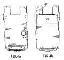
- FIGS. 4 a and 4 bshow the primary and secondary sides, respectively, of a printed circuit board of the adapter according to the present invention.
- Connector JP 1interfaces electronics on the circuit board with a scanner module.
- An external connector JH 1interfaces electronics on the circuit board with the iPAQ PDA.
- a 68-pin connector JH 2interfaces electronics on the circuit board with a PC card having radio or other functionality.
- the adapterintegrates both the scanner module and the radio module, together with an antenna, inside it. Some of the electronic components between the two modules can be shared.
- the modulesare not integrated inside the adapter, but are selectively plugged into the adapter.
- either the JP 1 or JH 2must also be an external connector.
- the adapterhas a PCMCIA compatible connector
- any PCMCIA compatible modulecan be plugged into the adapter, thus expanding system flexibility even further.
- Module compatible interface connectorsother than the PCMCIA interface connectors are envisioned to be within the scope of the present invention.
- the adaptermust have a PDA compatible connector for interfacing to the PDA, the expansion module connector is optional.
- FIGS. 8–13are drawings of an alternative embodiment of the present invention.
- the adapter 200includes a cover 204 and a carrier 206 .
- the carrier 206includes a bottom wall 208 and two sidewalls 210 extending from bottom wall 208 .
- Curved portions 211 of sidewalls 210 of carrier 206are curved in such a way that they partially cover the sides of the PDA. Curved portions 211 protect the PDA from side-to-side movement and side impact. Curved portions 211 also prevent adapter 200 from being pulled off the PDA and protect the PDA from front impact.
- the adapter of FIG. 8 ashows an adapter having an integrated scanner located behind the scanning window 220 .
- Sidewalls 210include a gripping surface 213 for improved ergonomics.
- the overall thickness of adaptermay increase. Users with small hands may have difficulty wrapping their fingers all the way around to the curved portion of the sidewalls.
- Gripping surface 213provides a surface for these users to place their fingertips allowing them to grasp the adapter in a secure manner. Users with larger hands may choose to place their fingertips either on the side of the PDA or on gripping surface 213 .
- the gripping surface 213When viewing the adapter from a horizontal position, the gripping surface 213 has a portion that is below bottom wall 208 and a portion that is above bottom wall 208 .
- gripping surface 213has a portion that radiates in an outward direction relative to a vertical axis 270 .
- An angle ⁇is formed along vertical axis 270 and the gripping surface 213 . Angle ⁇ may change depending on where along gripping surface 213 it is measured.
- An angle ⁇is formed along vertical axis 270 and a side section 215 above the gripping surface 213 .
- Side section 215consists of portions of carrier 206 and cover 204 (not shown in FIG. 13 ).
- FIG. 13shows a seam 217 where carrier 206 meets cover 204 .
- the side sectioncould consist of portions of only the carrier or only the cover.
- Gripping surface 213 and side section 215meet to form a ridge 260 . Ridge 260 improves the ergonomics of adapter 200 and helps prevent a user's fingers from slipping off gripping surface 213 .
- FIG. 10shows a notch 280 where a tether or strap (not shown) can be attached to adapter 200 .
- the tetherallows the operator to carry the device without worrying about dropping it.
- the tetheris preferably attached to the top of adapter 200 so if adapter 200 hangs from the tether the PDA would be in an upright position and less likely to slip out of the adapter.
- Adapter 200 shown in the embodiment of FIGS. 8–13does not have a retainer clip.
- adapter 200could include a retainer clip to lock the adapter and the PDA together as shown in the embodiments of FIGS. 1 a, 1 b, 1 e, 1 f and 1 g.
- curved portions 211restrict the side-to-side movements of the PDA with respect to adapter 200 .
- Adapter connector 224restricts movement of the PDA along the length of adapter 200 .
- a connector interface 205is flexibly secured to adapter 200 .
- Connector interface 205may be secured by a spring or similar arrangement to allow it to move in an orthogonal direction relative to the bottom wall 208 .
- the connector interface 205has ribbed members 205 a that engage with a receiving receptacle on the PDA (not shown).
- PDAreceiving receptacle
- connector interface 205is forced down until the PDA's receiving receptacle engages ribbed members 205 a.
- ribbed members 205a spring up into the PDA's receiving receptacle creating an audible click. The audible click notifies the user that adapter 200 is fully secured to the PDA.
- FIG. 5illustrates an adapter having a hand strap 130 .
- Hand strap 130is attached to the top of the adapter and allows the operator to carry the device without worrying about dropping it.
- the adapterwhich is typically made out of plastic material, can have a rubber over-mold with a finger grip designed into it.
- FIG. 6shows compartment for a rechargeable, or a disposable, battery located inside the adapter.
- the batteryis accessed via a battery door 140 that forms a part of the adapter's top cover.
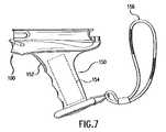
- FIG. 7shows an adapter having a handle grip 150 extending from the surface of the adapter.
- Handle grip 150may be detachable from the adapter.
- handle grip 150includes a trigger mechanism 152 for triggering (“energizing”) the module that is integrated inside the adapter.
- Handle grip 150has a battery compartment 154 inside it, such that the device can be operated for longer periods of time.
- the adaptermay not have any batteries inside, and would receive its power from handle grip 150 .
- Handle grip 150also includes a wrist tether 156 allowing the operator to carry the device without having to grip it.
- a usercan change the functionality of one or more of the application buttons on the PDA in a manner that is seamless to the user.
- one of the buttons on the PDAmay be dedicated to functioning as an audio recording button.
- the usermay want to use that button to trigger a scanning operation instead of audio recording.
- the functionality of the buttonmay be reconfigured to a scanning function without any additional steps by the user.
- FIG. 14shows a flowchart representing a configuration routine for a preferred embodiment of the present invention.
- Step 302represents a PDA having an application button that is assigned a certain function.
- the adapterincludes nonvolatile memory that includes a configuration program.
- the configuration programmay include a program that includes routines for changing the functionality of one or more of the application buttons on the PDA.
- the configuration programchanges application button mappings within the PDA to produce the desired functionality.
- a devicesuch as an adapter
- the PDAwill run the configuration program at 306 .
- the configuration programwill change the application button mapping in the PDA to change the functionality of one or more of the application buttons from an original function to a reconfigured function.
- the reconfigured function of the buttonwill preferably be related to a function that was added by the attachment of the adapter to the PDA.
- FIG. 15shows a flowchart representing a configuration routine for another preferred embodiment of the present invention.
- Step 312represents the PDA having an application button with a certain function wherein the PDA has a configuration program stored in a memory. Alternatively, the configuration program could reside on a remote site that is accessible by the PDA.
- the PDAcould poll its expansion connector to detect the presence of any attached devices.
- An attachable device(such as an adapter) may have associated with it an identification code.
- the identification codemay include a portion that identifies a manufacturer and a portion that identifies a device. If the device is attached to the PDA, the PDA will check the identification code of the attached device at 316 .
- the PDAaccesses configuration data that provides information for the PDA to change the functionality of the application buttons.
- the configuration datamay be determined by accessing a look up table (stored either locally on the PDA or remotely).
- the devicemay store the reconfiguration data in the device's nonvolatile memory.
- the configuration programmay change the application button mapping in the PDA in order to change the functionality of one or more of the application buttons from an original function to a reconfigured function.
- the change of function of the buttonsis seamless to the user.
- the reconfigured function of the buttonwill preferably be related to a function that was added by the attachment of the device to the PDA.
- FIG. 16shows a flowchart representing a configuration routine for a preferred embodiment wherein the adapter is removed from the PDA.
- Step 322represents the PDA having an application button with a certain reconfigured function. In this preferred embodiment of the invention, the reconfigured function of the application button will revert back to the original function when the adapter is removed.
- the PDAmay include a routine for polling the PDA's expansion connector to determine whether any devices are attached.
- the PDApolls the expansion connector. If the polling routine determines that an adapter is no longer connected to the PDA, the configuration program may be activated at 326 .
- the configuration programmay change the application button mapping in the PDA in order to change the functionality of the application buttons from the reconfigured function back to the original function.
- the adaptermay include a memory backup system.
- the memory backup systemhelps prevent the PDA from losing information stored in the PDA's volatile memory in the event that the PDA's battery source is critically low.
- PDA'stypically include a battery monitoring circuit that monitors the PDA's battery source to determine an energy level. If the energy level falls below a certain shut down value, the PDA automatically shuts down. The manufacturer or programmer of the PDA sets the shut down value to be large enough so that some power is reserved to maintain the contents of the PDA's volatile memory. However, this system does not guarantee that the contents of the PDA's volatile memory will be preserved. The energy level may continue to decrease over time until the data stored in the volatile memory becomes irretrievable.
- FIG. 17shows a flowchart representing a memory backup system for a preferred embodiment of the present invention.
- Step 332represents a PDA having a volatile memory attached to an adapter.
- the adapterhas a nonvolatile memory capable of storing data and application programs.
- the systemmeasures the energy level of the battery source at 334 and compares the energy level to a certain backup value at 336 . If the energy level of the battery source falls below the backup value, at step 338 the data stored in the PDA's volatile memory is copied in the adapter's nonvolatile memory or to a remote storage area.
- the remote storage areamay include a facility linked to a wide area network or a local area network.
- the backup valuemay be set to be equal to or different than the shut down value. If the data stored in the PDA's volatile memory is irretrievable because the energy level of the battery source is too low to maintain the memory, the data may be reconstructed by using the data stored in the adapter's nonvolatile memory.
Landscapes
- Engineering & Computer Science (AREA)
- Theoretical Computer Science (AREA)
- Computer Hardware Design (AREA)
- Human Computer Interaction (AREA)
- Physics & Mathematics (AREA)
- General Engineering & Computer Science (AREA)
- General Physics & Mathematics (AREA)
- Telephone Set Structure (AREA)
Abstract
Description
Claims (19)
Priority Applications (1)
| Application Number | Priority Date | Filing Date | Title |
|---|---|---|---|
| US10/790,367US7147163B2 (en) | 2001-01-23 | 2004-03-01 | Adapter unit having an ergonomic grip for a personal digital assistant |
Applications Claiming Priority (3)
| Application Number | Priority Date | Filing Date | Title |
|---|---|---|---|
| US26343801P | 2001-01-23 | 2001-01-23 | |
| US09/912,162US6820813B2 (en) | 2001-01-23 | 2001-07-24 | Adapter unit having an ergonomic grip for a personal digital assistant |
| US10/790,367US7147163B2 (en) | 2001-01-23 | 2004-03-01 | Adapter unit having an ergonomic grip for a personal digital assistant |
Related Parent Applications (1)
| Application Number | Title | Priority Date | Filing Date |
|---|---|---|---|
| US09/912,162ContinuationUS6820813B2 (en) | 2001-01-23 | 2001-07-24 | Adapter unit having an ergonomic grip for a personal digital assistant |
Publications (2)
| Publication Number | Publication Date |
|---|---|
| US20040166896A1 US20040166896A1 (en) | 2004-08-26 |
| US7147163B2true US7147163B2 (en) | 2006-12-12 |
Family
ID=26949849
Family Applications (2)
| Application Number | Title | Priority Date | Filing Date |
|---|---|---|---|
| US09/912,162Expired - LifetimeUS6820813B2 (en) | 2001-01-23 | 2001-07-24 | Adapter unit having an ergonomic grip for a personal digital assistant |
| US10/790,367Expired - LifetimeUS7147163B2 (en) | 2001-01-23 | 2004-03-01 | Adapter unit having an ergonomic grip for a personal digital assistant |
Family Applications Before (1)
| Application Number | Title | Priority Date | Filing Date |
|---|---|---|---|
| US09/912,162Expired - LifetimeUS6820813B2 (en) | 2001-01-23 | 2001-07-24 | Adapter unit having an ergonomic grip for a personal digital assistant |
Country Status (1)
| Country | Link |
|---|---|
| US (2) | US6820813B2 (en) |
Cited By (20)
| Publication number | Priority date | Publication date | Assignee | Title |
|---|---|---|---|---|
| US20060082978A1 (en)* | 2004-10-18 | 2006-04-20 | Chien-Jui Wang | Electronic device having a jacket capable of being attracted to a main body |
| US20070069030A1 (en)* | 2005-09-28 | 2007-03-29 | Sauerwein James T Jr | Data collection device and network having radio signal responsive mode switching |
| US20070235370A1 (en)* | 2006-03-31 | 2007-10-11 | Anthony Reale | Protective chassis cover system and method |
| US20080228982A1 (en)* | 2007-03-16 | 2008-09-18 | Microsoft Corporation | Modular Expandable Mobile Navigation Device |
| USD585069S1 (en)* | 2007-01-12 | 2009-01-20 | Symbol Technologies, Inc. | Protective frame for a mobile device |
| US20090021485A1 (en)* | 2007-07-16 | 2009-01-22 | Rochelle Shapera-Gill | Ergonomic thumb support device for a hand-held device |
| US20090146031A1 (en)* | 2006-07-20 | 2009-06-11 | A. Raymond Et Cie | Device for fastening a rectangular sensor to a support part |
| US7577516B2 (en) | 2006-05-09 | 2009-08-18 | Hand Held Products, Inc. | Power management apparatus and methods for portable data terminals |
| US20100210329A1 (en)* | 2009-02-13 | 2010-08-19 | Michael Merz | Hand held, ergonomic grip having a portable telephone device removably coupled thereto |
| US20100220435A1 (en)* | 2008-10-20 | 2010-09-02 | Fahey James T | Peripheral data storage device with dock charge pass-through connector and optional microsd slots and accompanying device and host software for apple iphone and ipod devices |
| US7983034B1 (en)* | 2008-09-19 | 2011-07-19 | Victor Mohoney | Docking system for MP3 players and other portable electronic devices |
| US8523068B2 (en) | 2010-12-23 | 2013-09-03 | Verifone, Inc. | Point of sale terminal for engagement with a mobile communicator |
| US20140034531A1 (en)* | 2012-08-03 | 2014-02-06 | Ching-Chang Wang | Protection Device for Electronic Equipment |
| US20140043740A1 (en)* | 2001-11-19 | 2014-02-13 | Otter Products, Llc | Protective enclosure for electronic device |
| USD707687S1 (en)* | 2013-03-07 | 2014-06-24 | Election Administrators, Llc | Device for scanning bar codes on identification cards using a tablet computer |
| USD707686S1 (en)* | 2012-09-11 | 2014-06-24 | Election Administrators, Llc | Device for scanning bar codes on identification cards using a tablet computer |
| US8763909B2 (en) | 2011-01-04 | 2014-07-01 | Hand Held Products, Inc. | Terminal comprising mount for supporting a mechanical component |
| US20170277224A1 (en)* | 2015-01-16 | 2017-09-28 | Mitsubishi Electric Corporation | Cradle and terminal device control method |
| US11317050B2 (en) | 2005-03-11 | 2022-04-26 | Hand Held Products, Inc. | Image reader comprising CMOS based image sensor array |
| US11604933B2 (en) | 2005-06-03 | 2023-03-14 | Hand Held Products, Inc. | Apparatus having hybrid monochrome and color image sensor array |
Families Citing this family (25)
| Publication number | Priority date | Publication date | Assignee | Title |
|---|---|---|---|---|
| TW560164B (en)* | 2001-05-11 | 2003-11-01 | Veutron Corp | Palmtop office machine with scanning function |
| TW549737U (en)* | 2002-10-08 | 2003-08-21 | Lite On Technology Corp | Modularized and common-used PDA connector |
| US7147162B2 (en)* | 2003-01-09 | 2006-12-12 | Hand Held Products, Inc. | Housing for an optical reader |
| JP2005217621A (en)* | 2004-01-28 | 2005-08-11 | Kyocera Corp | Mobile communication terminal and communication system |
| US9270769B1 (en) | 2004-08-11 | 2016-02-23 | Aol Inc. | Mobile communications device |
| USD517557S1 (en)* | 2004-12-28 | 2006-03-21 | Paul Brassard | PDA mount |
| USD566118S1 (en)* | 2005-03-17 | 2008-04-08 | Paul Brassard | Holding apparatus |
| US7913961B2 (en)* | 2005-10-22 | 2011-03-29 | Paul James Del Frari | Hand grip for palm-held devices |
| GB2469860A (en)* | 2009-04-30 | 2010-11-03 | Luckybite Llp | Apparatus for integrating with a handheld computing device. |
| USD632693S1 (en)* | 2009-09-04 | 2011-02-15 | Brahler Ics Konferenztechnik International Congress Service Ag | Docking station with a removable battery for a conference communication unit |
| USD644228S1 (en)* | 2010-06-24 | 2011-08-30 | Savant Systems Llc | In-wall iPad dock |
| USD644229S1 (en)* | 2010-06-24 | 2011-08-30 | Savant Systems Llc | In-wall iPod dock |
| USD676447S1 (en)* | 2010-09-03 | 2013-02-19 | Thomas Detemple | Personal electronic device docking station |
| USD673156S1 (en)* | 2010-09-03 | 2012-12-25 | Thomas Detemple | Personal electronic device docking station |
| USD660840S1 (en)* | 2011-02-28 | 2012-05-29 | Kuo Hsiung Chen | Vehicle mounted docking station for electronic device |
| USD673957S1 (en)* | 2011-10-14 | 2013-01-08 | Compal Electronics, Inc. | Notebook computer connector |
| USD680116S1 (en)* | 2011-12-14 | 2013-04-16 | Seagate Technology Llc | Cartridge interface |
| US8646698B2 (en)* | 2012-02-15 | 2014-02-11 | Tennrich International Corp. | Protective cover of mobile electronic product |
| US10050658B2 (en) | 2014-02-24 | 2018-08-14 | National Products, Inc. | Docking sleeve with electrical adapter |
| US11489350B2 (en)* | 2019-12-23 | 2022-11-01 | National Products, Inc. | Cradle for mobile devices with resilient guides and methods of making and using |
| US11277506B2 (en) | 2020-05-26 | 2022-03-15 | National Products, Inc. | Cradles for mobile devices with one or more biasing tabs and methods of making and using |
| US11652326B2 (en) | 2021-04-30 | 2023-05-16 | National Products, Inc. | Dock with flexible locator pins and methods of making and using |
| US12126199B2 (en) | 2021-08-09 | 2024-10-22 | National Products, Inc. | Cradles for a mobile device including a cavity for a wireless device and methods of making and using |
| US12158776B2 (en) | 2022-04-25 | 2024-12-03 | National Products, Inc. | Docks for mobile devices with simultaneous data transfer and charging and systems and methods using the docks |
| US12298809B2 (en) | 2023-07-05 | 2025-05-13 | National Products, Inc. | Heating module for electronic device dock and methods of making and using |
Citations (42)
| Publication number | Priority date | Publication date | Assignee | Title |
|---|---|---|---|---|
| US4983818A (en) | 1989-01-30 | 1991-01-08 | Metrologic Instruments, Inc. | Data acquisition system with laser scanner module |
| US5218187A (en) | 1990-01-18 | 1993-06-08 | Norand Corporation | Hand-held data capture system with interchangeable modules |
| US5313053A (en) | 1990-01-18 | 1994-05-17 | Norand Corporation | Laser scanner module having integral interfacing with hand-held data capture terminal |
| US5335170A (en) | 1992-09-04 | 1994-08-02 | Comtec Information Systems, Inc. | Modular system for inventory control |
| US5349497A (en) | 1989-06-07 | 1994-09-20 | Norand Corporation | Detachable handle structures for terminals |
| USD352279S (en) | 1992-11-02 | 1994-11-08 | International Business Machines Incorporated | Portable computer tablet with a touch screen and stylus |
| US5368159A (en) | 1991-06-14 | 1994-11-29 | Daniels S.R.L. | Protection case for remote controls |
| US5388692A (en) | 1994-01-03 | 1995-02-14 | Withrow; Joseph E. | Lighting cover for a remote control unit |
| US5539194A (en) | 1989-06-07 | 1996-07-23 | Norand Corporation | Modular hand-held data entry system |
| US5606594A (en) | 1994-01-27 | 1997-02-25 | Dell Usa, L.P. | Communication accessory and method of telecommunicating for a PDA |
| US5627349A (en)* | 1993-07-01 | 1997-05-06 | Integral Information Systems | Interactive data entry apparatus |
| USD379265S (en) | 1995-11-08 | 1997-05-20 | Harris Corporation | Portable computer carrying case |
| US5648757A (en) | 1994-10-24 | 1997-07-15 | Vernace; Salvatore J. | Remote control protective holder and detection device |
| US5675524A (en) | 1993-11-15 | 1997-10-07 | Ete Inc. | Portable apparatus for providing multiple integrated communication media |
| US5692199A (en) | 1993-10-28 | 1997-11-25 | Elonex I.P. Holdings, Ltd. | Personal digital assistant module having a host interconnect bus without an interrupt line and which handles interrupts as addresses associated with specific interrupts in memory |
| US5822546A (en) | 1996-03-08 | 1998-10-13 | George; Stanley W. | Hand held docking station with deployable light source, rechargeable battery pack and recessed grip, for connecting to a palm top computer |
| US5859628A (en) | 1994-01-05 | 1999-01-12 | Pois, Inc. | Apparatus and method for a personal onboard information system |
| US5867729A (en) | 1995-08-23 | 1999-02-02 | Toshiba America Information Systems, Inc. | System for reconfiguring a keyboard configuration in response to an event status information related to a computer's location determined by using triangulation technique |
| US5890016A (en)* | 1996-05-07 | 1999-03-30 | Intel Corporation | Hybrid computer add in device for selectively coupling to personal computer or solely to another add in device for proper functioning |
| US5900875A (en) | 1997-01-29 | 1999-05-04 | 3Com Corporation | Method and apparatus for interacting with a portable computer system |
| US5914481A (en) | 1986-08-08 | 1999-06-22 | Norand Corporation | Portable data collection terminal with handwritten input area |
| US5979770A (en) | 1997-06-26 | 1999-11-09 | Symbol Technologies, Inc. | Data acquisition device having a resilient seal interposed between the head portion and the handle portion for rest stand |
| US5996956A (en) | 1997-06-17 | 1999-12-07 | Shawver; Michael | Mounting platform for an electronic device |
| US6042478A (en) | 1997-02-10 | 2000-03-28 | Tiger Electronics, Ltd. | Hand held video game |
| USD424035S (en) | 1999-02-16 | 2000-05-02 | Symbol Technologies, Inc. | Protective terminal cover |
| US6065880A (en)* | 1998-03-09 | 2000-05-23 | 3Com Corporation | Laser enhanced personal data assistant |
| USD426549S (en) | 1999-10-12 | 2000-06-13 | Mitsubishi Electric Information Technology Center America, Inc. (ITA.) | Slide-on accessory for a personal digital assistant |
| US6115248A (en) | 1999-05-17 | 2000-09-05 | Palm, Inc. | Detachable securement of an accessory device to a handheld computer |
| US6195589B1 (en) | 1998-03-09 | 2001-02-27 | 3Com Corporation | Personal data assistant with remote control capabilities |
| US6244513B1 (en) | 1999-11-09 | 2001-06-12 | Symbol Technologies, Inc. | Data acquisition apparatus |
| US6300946B1 (en) | 1997-01-29 | 2001-10-09 | Palm, Inc. | Method and apparatus for interacting with a portable computer |
| US6330973B1 (en) | 1989-10-30 | 2001-12-18 | Symbol Technologies, Inc. | Integrated code reading systems including tunnel scanners |
| US20020078248A1 (en) | 2000-09-05 | 2002-06-20 | Janik Craig M. | Adapter module for a personal digital assistant and method for using the same |
| US6512467B1 (en) | 1999-04-09 | 2003-01-28 | Sun Microsystems, Inc. | Method and apparatus for dynamically configuring device using device code |
| US6535199B1 (en) | 1999-02-04 | 2003-03-18 | Palm, Inc. | Smart cover for a handheld computer |
| US6600657B1 (en) | 1999-10-12 | 2003-07-29 | Mitsubishi Electric Research Laboratories, Inc. | Accessory adapted for digital personal assistant |
| US6604684B1 (en) | 1993-11-24 | 2003-08-12 | Metrologic Instruments Inc. | Automatic optical projection scanner for omni-directional reading of bar code symbols within a confined scanning volume |
| US6619546B1 (en) | 2002-03-14 | 2003-09-16 | Wal-Mart Stores, Inc. | Systems and methods for pre-scanning merchandise in customer's shopping cart while customer is waiting in checkout line |
| US20030181168A1 (en) | 1997-08-05 | 2003-09-25 | Allan Herrod | Terminal with optical reader for locating products in a retail establishment |
| US6657654B2 (en)* | 1998-04-29 | 2003-12-02 | International Business Machines Corporation | Camera for use with personal digital assistants with high speed communication link |
| JP2004005164A (en)* | 2002-05-31 | 2004-01-08 | Denso Wave Inc | Optical information reader |
| US6708887B1 (en)* | 2001-08-18 | 2004-03-23 | Gsl Solutions, Inc. | Detachable hand-held computer handle |
Family Cites Families (35)
| Publication number | Priority date | Publication date | Assignee | Title |
|---|---|---|---|---|
| US3019676A (en)* | 1959-11-04 | 1962-02-06 | Andrew A Bogdan | Fly cutter with micrometrical adjustment |
| US4165554A (en)* | 1978-06-12 | 1979-08-28 | Faget Charles J | Hand-held portable calculator assembly |
| US4496831A (en)* | 1980-02-29 | 1985-01-29 | Symbol Technologies, Inc. | Portable laser scanning system and scanning methods |
| US5262628A (en)* | 1982-01-25 | 1993-11-16 | Symbol Technologies, Inc. | Narrow-bodied, single- and twin-windowed portable laser scanning head for reading bar code symbols |
| DE3687127T2 (en)* | 1985-02-28 | 1993-05-06 | Symbol Technologies Inc | PORTABLE SCAN HEAD WITH A LASER DIODE. |
| US5227614A (en)* | 1986-08-15 | 1993-07-13 | Norand Corporation | Core computer processor module, and peripheral shell module assembled to form a pocket size data capture unit |
| US5672860A (en)* | 1987-12-21 | 1997-09-30 | Norand Corporation | Integrated hand-held bar code processing device capable of automatic scan and data display |
| US4896026A (en)* | 1988-10-31 | 1990-01-23 | Symbol Technologies, Inc. | Laser diode scanner with improved shock mounting |
| US5023438A (en)* | 1988-11-26 | 1991-06-11 | Nitto Kohki Co., Ltd. | Portable data input apparatus with different display modes |
| US5049862A (en)* | 1989-10-06 | 1991-09-17 | Communication Intelligence Corporation ("Cic") | Keyless flat panel portable computer--computer aided notebook |
| US5589679A (en)* | 1989-10-30 | 1996-12-31 | Symbol Technologies, Inc. | Parallelepiped-shaped optical scanning module |
| US5092793A (en)* | 1990-04-23 | 1992-03-03 | John Stephan | Swivel apparatus providing strain relief for an electrical conductor |
| US5200597A (en)* | 1991-02-07 | 1993-04-06 | Psc, Inc. | Digitally controlled system for scanning and reading bar codes |
| US5237162A (en)* | 1991-06-10 | 1993-08-17 | Spectra-Physics Scanning Systems, Inc. | Handheld laser scanner with contoured hand rest |
| US5475381A (en)* | 1992-01-28 | 1995-12-12 | Servio Logic Corp. | High speed infrared communications system using pulse sets |
| US5236129A (en)* | 1992-05-27 | 1993-08-17 | Ransburg Corporation | Ergonomic hand held paint spray gun |
| US5378882A (en)* | 1992-09-11 | 1995-01-03 | Symbol Technologies, Inc. | Bar code symbol reader with locking cable connector assembly |
| US5406063A (en)* | 1993-05-07 | 1995-04-11 | Telxon Corporation | Hand-held data scanner having adjustable keyboard panel |
| USD349559S (en)* | 1993-10-18 | 1994-08-09 | Ransburg Corporation | Spray gun handle cover |
| US5402152A (en)* | 1993-12-30 | 1995-03-28 | Intel Corporation | Method and apparatus for tailoring scroll bar and cursor appearance to pen user hand orientation |
| US5479001A (en)* | 1994-07-22 | 1995-12-26 | Khyber Technologies Corporation | Right- and left-handed operable, grip-held pen computing device with removable data entry modules |
| US5742894A (en)* | 1995-02-06 | 1998-04-21 | Motorola, Inc. | Radio communication device having a moveable housing element and keypad disposed therein |
| US5600121A (en)* | 1995-03-20 | 1997-02-04 | Symbol Technologies, Inc. | Optical reader with independent triggering and graphical user interface |
| US5594232A (en)* | 1995-05-05 | 1997-01-14 | Symbol Technologies, Inc. | Planar arrangement for two-dimensional optical scanning |
| US5996080A (en)* | 1995-10-04 | 1999-11-30 | Norand Corporation | Safe, virtual trigger for a portable data capture terminal |
| DE69603751T2 (en)* | 1995-12-22 | 2000-04-06 | G. Lyle Habermehl | POWERED HAND TOOL WITH ONE SWITCH IN THE REAR PART OF AN ERGONOMIC HANDLE |
| US5736726A (en)* | 1996-03-29 | 1998-04-07 | Telxon Corporation | Portable data collection device having removable handle and battery |
| US5979757A (en)* | 1996-09-05 | 1999-11-09 | Symbol Technologies, Inc. | Method and system for presenting item information using a portable data terminal |
| USD387754S (en)* | 1996-10-09 | 1997-12-16 | Intermec Corporation | Head portion of a scanner |
| USD387753S (en)* | 1996-10-09 | 1997-12-16 | Intermec Corporation | Hilt portion of a scanner |
| US5828052A (en)* | 1996-10-24 | 1998-10-27 | Intermec Corporation | Ergonometric modular hand-held scanner, including an ergonomic handle and hilt |
| US5973677A (en)* | 1997-01-07 | 1999-10-26 | Telxon Corporation | Rechargeable, untethered electronic stylus for computer with interactive display screen |
| US6119179A (en)* | 1998-08-28 | 2000-09-12 | Pda Peripherals Inc. | Telecommunications adapter providing non-repudiable communications log and supplemental power for a portable programmable device |
| US6502754B1 (en)* | 1999-03-01 | 2003-01-07 | Symbol Technologies, Inc. | Data acquisition device |
| US6496874B1 (en)* | 1999-06-30 | 2002-12-17 | Trimble Navigation Limited | Method and apparatus for determining position using a handheld personal computer and a cradle |
- 2001
- 2001-07-24USUS09/912,162patent/US6820813B2/ennot_activeExpired - Lifetime
- 2004
- 2004-03-01USUS10/790,367patent/US7147163B2/ennot_activeExpired - Lifetime
Patent Citations (44)
| Publication number | Priority date | Publication date | Assignee | Title |
|---|---|---|---|---|
| US5914481A (en) | 1986-08-08 | 1999-06-22 | Norand Corporation | Portable data collection terminal with handwritten input area |
| US4983818A (en) | 1989-01-30 | 1991-01-08 | Metrologic Instruments, Inc. | Data acquisition system with laser scanner module |
| US5349497A (en) | 1989-06-07 | 1994-09-20 | Norand Corporation | Detachable handle structures for terminals |
| US5539194A (en) | 1989-06-07 | 1996-07-23 | Norand Corporation | Modular hand-held data entry system |
| US6330973B1 (en) | 1989-10-30 | 2001-12-18 | Symbol Technologies, Inc. | Integrated code reading systems including tunnel scanners |
| US5313053A (en) | 1990-01-18 | 1994-05-17 | Norand Corporation | Laser scanner module having integral interfacing with hand-held data capture terminal |
| US5218187A (en) | 1990-01-18 | 1993-06-08 | Norand Corporation | Hand-held data capture system with interchangeable modules |
| US5368159A (en) | 1991-06-14 | 1994-11-29 | Daniels S.R.L. | Protection case for remote controls |
| US5335170A (en) | 1992-09-04 | 1994-08-02 | Comtec Information Systems, Inc. | Modular system for inventory control |
| USD352279S (en) | 1992-11-02 | 1994-11-08 | International Business Machines Incorporated | Portable computer tablet with a touch screen and stylus |
| US5627349A (en)* | 1993-07-01 | 1997-05-06 | Integral Information Systems | Interactive data entry apparatus |
| US5692199A (en) | 1993-10-28 | 1997-11-25 | Elonex I.P. Holdings, Ltd. | Personal digital assistant module having a host interconnect bus without an interrupt line and which handles interrupts as addresses associated with specific interrupts in memory |
| US5675524A (en) | 1993-11-15 | 1997-10-07 | Ete Inc. | Portable apparatus for providing multiple integrated communication media |
| US6604684B1 (en) | 1993-11-24 | 2003-08-12 | Metrologic Instruments Inc. | Automatic optical projection scanner for omni-directional reading of bar code symbols within a confined scanning volume |
| US5388692A (en) | 1994-01-03 | 1995-02-14 | Withrow; Joseph E. | Lighting cover for a remote control unit |
| US5859628A (en) | 1994-01-05 | 1999-01-12 | Pois, Inc. | Apparatus and method for a personal onboard information system |
| US5606594A (en) | 1994-01-27 | 1997-02-25 | Dell Usa, L.P. | Communication accessory and method of telecommunicating for a PDA |
| US5648757A (en) | 1994-10-24 | 1997-07-15 | Vernace; Salvatore J. | Remote control protective holder and detection device |
| US5867729A (en) | 1995-08-23 | 1999-02-02 | Toshiba America Information Systems, Inc. | System for reconfiguring a keyboard configuration in response to an event status information related to a computer's location determined by using triangulation technique |
| USD379265S (en) | 1995-11-08 | 1997-05-20 | Harris Corporation | Portable computer carrying case |
| US5822546A (en) | 1996-03-08 | 1998-10-13 | George; Stanley W. | Hand held docking station with deployable light source, rechargeable battery pack and recessed grip, for connecting to a palm top computer |
| US5890016A (en)* | 1996-05-07 | 1999-03-30 | Intel Corporation | Hybrid computer add in device for selectively coupling to personal computer or solely to another add in device for proper functioning |
| US5900875A (en) | 1997-01-29 | 1999-05-04 | 3Com Corporation | Method and apparatus for interacting with a portable computer system |
| US6300946B1 (en) | 1997-01-29 | 2001-10-09 | Palm, Inc. | Method and apparatus for interacting with a portable computer |
| US20030001909A1 (en) | 1997-01-29 | 2003-01-02 | Haitani Robert Yuji | Method and apparatus for interacting with a portable computer system |
| US6042478A (en) | 1997-02-10 | 2000-03-28 | Tiger Electronics, Ltd. | Hand held video game |
| US5996956A (en) | 1997-06-17 | 1999-12-07 | Shawver; Michael | Mounting platform for an electronic device |
| US5979770A (en) | 1997-06-26 | 1999-11-09 | Symbol Technologies, Inc. | Data acquisition device having a resilient seal interposed between the head portion and the handle portion for rest stand |
| US6123265A (en) | 1997-06-26 | 2000-09-26 | Symbol Technologies, Inc. | Data acquisition device having a resilient seal interposed between the head portion and the handle portion for rest stand |
| US20030181168A1 (en) | 1997-08-05 | 2003-09-25 | Allan Herrod | Terminal with optical reader for locating products in a retail establishment |
| US6195589B1 (en) | 1998-03-09 | 2001-02-27 | 3Com Corporation | Personal data assistant with remote control capabilities |
| US6065880A (en)* | 1998-03-09 | 2000-05-23 | 3Com Corporation | Laser enhanced personal data assistant |
| US6657654B2 (en)* | 1998-04-29 | 2003-12-02 | International Business Machines Corporation | Camera for use with personal digital assistants with high speed communication link |
| US6535199B1 (en) | 1999-02-04 | 2003-03-18 | Palm, Inc. | Smart cover for a handheld computer |
| USD424035S (en) | 1999-02-16 | 2000-05-02 | Symbol Technologies, Inc. | Protective terminal cover |
| US6512467B1 (en) | 1999-04-09 | 2003-01-28 | Sun Microsystems, Inc. | Method and apparatus for dynamically configuring device using device code |
| US6115248A (en) | 1999-05-17 | 2000-09-05 | Palm, Inc. | Detachable securement of an accessory device to a handheld computer |
| USD426549S (en) | 1999-10-12 | 2000-06-13 | Mitsubishi Electric Information Technology Center America, Inc. (ITA.) | Slide-on accessory for a personal digital assistant |
| US6600657B1 (en) | 1999-10-12 | 2003-07-29 | Mitsubishi Electric Research Laboratories, Inc. | Accessory adapted for digital personal assistant |
| US6244513B1 (en) | 1999-11-09 | 2001-06-12 | Symbol Technologies, Inc. | Data acquisition apparatus |
| US20020078248A1 (en) | 2000-09-05 | 2002-06-20 | Janik Craig M. | Adapter module for a personal digital assistant and method for using the same |
| US6708887B1 (en)* | 2001-08-18 | 2004-03-23 | Gsl Solutions, Inc. | Detachable hand-held computer handle |
| US6619546B1 (en) | 2002-03-14 | 2003-09-16 | Wal-Mart Stores, Inc. | Systems and methods for pre-scanning merchandise in customer's shopping cart while customer is waiting in checkout line |
| JP2004005164A (en)* | 2002-05-31 | 2004-01-08 | Denso Wave Inc | Optical information reader |
Non-Patent Citations (3)
| Title |
|---|
| Mike Lynch, "The Silver Slider II", Pocket PC Editor, BrightHand Consulting, Inc., Feb. 19, 2001. |
| Pravin Bhagwat, "BlueSky: A Cordless Networking Solution for Palmtop Computers," ACM Press, Proceedings of the 5th Annual ACM/IEEE International Conference on Mobile Computing and Networking, 1999, pp. 69-76. |
| Saila Ponnapalli, "Modeling and Design of Antennas for RF Wireless Systems," IEEE Transactions on Advanced Packaging, Aug, 1996, pp. 487-502, vol. 19, Issue 3. |
Cited By (56)
| Publication number | Priority date | Publication date | Assignee | Title |
|---|---|---|---|---|
| US9735827B2 (en) | 2001-11-19 | 2017-08-15 | Otter Products, Llc | Protective enclosure for electronic device |
| US8917496B2 (en)* | 2001-11-19 | 2014-12-23 | Otter Products, Llc | Protective enclosure for electronic device |
| US8922985B2 (en) | 2001-11-19 | 2014-12-30 | Otter Poducts, LLC | Protective enclosure for electronic device |
| US8976512B2 (en) | 2001-11-19 | 2015-03-10 | Otter Products, Llc | Protective enclosure for electronic device |
| US20140043740A1 (en)* | 2001-11-19 | 2014-02-13 | Otter Products, Llc | Protective enclosure for electronic device |
| US8995127B2 (en) | 2001-11-19 | 2015-03-31 | Otter Products, Llc | Protective enclosure for electronic device |
| US9114923B2 (en) | 2001-11-19 | 2015-08-25 | Otter Products, Llc | Protective enclosure for electronic device |
| US9560435B2 (en) | 2001-11-19 | 2017-01-31 | Otter Products, Llc | Protective enclosure for electronic device |
| US10340970B2 (en) | 2001-11-19 | 2019-07-02 | Otter Products, Llc | Protective cover for electronic device |
| US10044396B2 (en) | 2001-11-19 | 2018-08-07 | Otter Products, Llc | Protective cover for electronic device |
| US9906259B2 (en) | 2001-11-19 | 2018-02-27 | Otter Products, Llc | Protective cover for electronic device |
| US20060082978A1 (en)* | 2004-10-18 | 2006-04-20 | Chien-Jui Wang | Electronic device having a jacket capable of being attracted to a main body |
| US11863897B2 (en) | 2005-03-11 | 2024-01-02 | Hand Held Products, Inc. | Image reader comprising CMOS based image sensor array |
| US11317050B2 (en) | 2005-03-11 | 2022-04-26 | Hand Held Products, Inc. | Image reader comprising CMOS based image sensor array |
| US11323650B2 (en) | 2005-03-11 | 2022-05-03 | Hand Held Products, Inc. | Image reader comprising CMOS based image sensor array |
| US11323649B2 (en) | 2005-03-11 | 2022-05-03 | Hand Held Products, Inc. | Image reader comprising CMOS based image sensor array |
| US11968464B2 (en) | 2005-03-11 | 2024-04-23 | Hand Held Products, Inc. | Image reader comprising CMOS based image sensor array |
| US12075176B2 (en) | 2005-03-11 | 2024-08-27 | Hand Held Products, Inc. | Image reader comprising CMOS based image sensor array |
| US12185006B2 (en) | 2005-03-11 | 2024-12-31 | Hand Held Products, Inc. | Image reader comprising CMOS based image sensor array |
| US11604933B2 (en) | 2005-06-03 | 2023-03-14 | Hand Held Products, Inc. | Apparatus having hybrid monochrome and color image sensor array |
| US11625550B2 (en) | 2005-06-03 | 2023-04-11 | Hand Held Products, Inc. | Apparatus having hybrid monochrome and color image sensor array |
| US12321814B2 (en) | 2005-06-03 | 2025-06-03 | Hand Held Products, Inc. | Apparatus having hybrid monochrome and color image sensor array |
| US12321815B2 (en) | 2005-06-03 | 2025-06-03 | Hand Held Products, Inc. | Apparatus having hybrid monochrome and color image sensor array |
| US12321813B2 (en) | 2005-06-03 | 2025-06-03 | Hand Held Products, Inc. | Apparatus having hybrid monochrome and color image sensor array |
| US12236312B2 (en) | 2005-06-03 | 2025-02-25 | Hand Held Products, Inc. | Apparatus having hybrid monochrome and color image sensor array |
| US12073283B2 (en) | 2005-06-03 | 2024-08-27 | Hand Held Products, Inc. | Apparatus having hybrid monochrome and color image sensor array |
| US12026580B2 (en) | 2005-06-03 | 2024-07-02 | Hand Held Products, Inc. | Apparatus having hybrid monochrome and color image sensor array |
| US12020111B2 (en) | 2005-06-03 | 2024-06-25 | Hand Held Products, Inc. | Apparatus having hybrid monochrome and color image sensor array |
| US12001914B2 (en) | 2005-06-03 | 2024-06-04 | Hand Held Products, Inc. | Apparatus having hybrid monochrome and color image sensor array |
| US12001913B2 (en) | 2005-06-03 | 2024-06-04 | Hand Held Products, Inc. | Apparatus having hybrid monochrome and color image sensor array |
| US8157168B2 (en) | 2005-09-28 | 2012-04-17 | Hand Held Products, Inc. | Data collection device and network having radio signal responsive operation |
| US7712670B2 (en) | 2005-09-28 | 2010-05-11 | Sauerwein Jr James T | Data collection device and network having radio signal responsive mode switching |
| US20100217723A1 (en)* | 2005-09-28 | 2010-08-26 | Hand Held Products, Inc. | Data collection device and network having radio signal responsive operation |
| US20070069030A1 (en)* | 2005-09-28 | 2007-03-29 | Sauerwein James T Jr | Data collection device and network having radio signal responsive mode switching |
| US8281993B2 (en) | 2005-09-28 | 2012-10-09 | Hand Held Products, Inc. | Data collection device and network having radio signal responsive operation |
| US20070235370A1 (en)* | 2006-03-31 | 2007-10-11 | Anthony Reale | Protective chassis cover system and method |
| US7577516B2 (en) | 2006-05-09 | 2009-08-18 | Hand Held Products, Inc. | Power management apparatus and methods for portable data terminals |
| US20090146031A1 (en)* | 2006-07-20 | 2009-06-11 | A. Raymond Et Cie | Device for fastening a rectangular sensor to a support part |
| US7780137B2 (en)* | 2006-07-20 | 2010-08-24 | A. Raymond Et Cie | Device for fastening a rectangular sensor to a support part |
| USD585069S1 (en)* | 2007-01-12 | 2009-01-20 | Symbol Technologies, Inc. | Protective frame for a mobile device |
| US7634606B2 (en) | 2007-03-16 | 2009-12-15 | Microsoft Corproation | Modular expandable mobile navigation device |
| US20080228982A1 (en)* | 2007-03-16 | 2008-09-18 | Microsoft Corporation | Modular Expandable Mobile Navigation Device |
| US20090021485A1 (en)* | 2007-07-16 | 2009-01-22 | Rochelle Shapera-Gill | Ergonomic thumb support device for a hand-held device |
| US8451599B1 (en) | 2008-09-19 | 2013-05-28 | Victor Mohoney | Docking system for MP3 players and other portable electronic devices |
| US7983034B1 (en)* | 2008-09-19 | 2011-07-19 | Victor Mohoney | Docking system for MP3 players and other portable electronic devices |
| US8228670B2 (en)* | 2008-10-20 | 2012-07-24 | James T Fahey | Peripheral storage device |
| US20100220435A1 (en)* | 2008-10-20 | 2010-09-02 | Fahey James T | Peripheral data storage device with dock charge pass-through connector and optional microsd slots and accompanying device and host software for apple iphone and ipod devices |
| US8208871B2 (en)* | 2009-02-13 | 2012-06-26 | Michael Merz | Hand held, ergonomic grip having a portable telephone device removably coupled thereto |
| US20100210329A1 (en)* | 2009-02-13 | 2010-08-19 | Michael Merz | Hand held, ergonomic grip having a portable telephone device removably coupled thereto |
| US8523068B2 (en) | 2010-12-23 | 2013-09-03 | Verifone, Inc. | Point of sale terminal for engagement with a mobile communicator |
| US8763909B2 (en) | 2011-01-04 | 2014-07-01 | Hand Held Products, Inc. | Terminal comprising mount for supporting a mechanical component |
| US20140034531A1 (en)* | 2012-08-03 | 2014-02-06 | Ching-Chang Wang | Protection Device for Electronic Equipment |
| USD707686S1 (en)* | 2012-09-11 | 2014-06-24 | Election Administrators, Llc | Device for scanning bar codes on identification cards using a tablet computer |
| USD707687S1 (en)* | 2013-03-07 | 2014-06-24 | Election Administrators, Llc | Device for scanning bar codes on identification cards using a tablet computer |
| US10175722B2 (en)* | 2015-01-16 | 2019-01-08 | Mitsubishi Electric Corporation | Cradle and terminal device control method |
| US20170277224A1 (en)* | 2015-01-16 | 2017-09-28 | Mitsubishi Electric Corporation | Cradle and terminal device control method |
Also Published As
| Publication number | Publication date |
|---|---|
| US20040166896A1 (en) | 2004-08-26 |
| US20030116631A1 (en) | 2003-06-26 |
| US6820813B2 (en) | 2004-11-23 |
Similar Documents
| Publication | Publication Date | Title |
|---|---|---|
| US7147163B2 (en) | Adapter unit having an ergonomic grip for a personal digital assistant | |
| US7337257B2 (en) | Adapter unit for a personal digital assistant having automatically configurable application buttons | |
| US6837435B2 (en) | Adapter unit having a handle grip for a personal digital assistant | |
| US5517434A (en) | Data capture system with communicating and recharging docking apparatus and hand-held data terminal means cooperable therewith | |
| US5808289A (en) | Arm mounted portable data collection device with rotatable and detachable dataform reader module | |
| US6052279A (en) | Customizable hand-held computer | |
| EP0655690B1 (en) | Removable processing modul for data processing system | |
| US5579487A (en) | Portable work slate computer with multiple docking positions for interchangeably receiving removable modules | |
| US5805416A (en) | Modular hand-held data capture terminal | |
| US5416730A (en) | Arm mounted computer | |
| US6518724B2 (en) | Wall switch device and power outlet device | |
| US7388742B2 (en) | Portable computerized data communication device | |
| US7315260B1 (en) | Integrated removable functional faceplate for portable computer system | |
| US20080225471A1 (en) | Housing protective cover and electronic apparatus system | |
| US20020050807A1 (en) | Device docking apparatus and method for using the same | |
| US20090322277A1 (en) | Portable computerized data communication device | |
| EP3561637B1 (en) | Portable terminal | |
| WO1996024093A1 (en) | Arm mounted computer | |
| EP1724659A2 (en) | Adapter unit having a handle grip for a personal digital assistant | |
| US20080225020A1 (en) | Electronic apparatus | |
| HK1100333A (en) | Adapter unit having a handle grip for a personal digital assistant | |
| KR200298222Y1 (en) | Portable keyboard and stand, and data input system using the same |
Legal Events
| Date | Code | Title | Description |
|---|---|---|---|
| AS | Assignment | Owner name:SYMBOL TECHNOLOGIES, INC., NEW YORK Free format text:ASSIGNMENT OF ASSIGNORS INTEREST;ASSIGNORS:SALVATO, DOMINICK H.;SASLOFF, MICHAEL J.;CROLEY, CURT D.;REEL/FRAME:015034/0359;SIGNING DATES FROM 20011219 TO 20021210 | |
| STCF | Information on status: patent grant | Free format text:PATENTED CASE | |
| CC | Certificate of correction | ||
| FPAY | Fee payment | Year of fee payment:4 | |
| FPAY | Fee payment | Year of fee payment:8 | |
| AS | Assignment | Owner name:MORGAN STANLEY SENIOR FUNDING, INC. AS THE COLLATERAL AGENT, MARYLAND Free format text:SECURITY AGREEMENT;ASSIGNORS:ZIH CORP.;LASER BAND, LLC;ZEBRA ENTERPRISE SOLUTIONS CORP.;AND OTHERS;REEL/FRAME:034114/0270 Effective date:20141027 Owner name:MORGAN STANLEY SENIOR FUNDING, INC. AS THE COLLATE Free format text:SECURITY AGREEMENT;ASSIGNORS:ZIH CORP.;LASER BAND, LLC;ZEBRA ENTERPRISE SOLUTIONS CORP.;AND OTHERS;REEL/FRAME:034114/0270 Effective date:20141027 | |
| AS | Assignment | Owner name:SYMBOL TECHNOLOGIES, LLC, NEW YORK Free format text:CHANGE OF NAME;ASSIGNOR:SYMBOL TECHNOLOGIES, INC.;REEL/FRAME:036083/0640 Effective date:20150410 | |
| AS | Assignment | Owner name:SYMBOL TECHNOLOGIES, INC., NEW YORK Free format text:RELEASE BY SECURED PARTY;ASSIGNOR:MORGAN STANLEY SENIOR FUNDING, INC.;REEL/FRAME:036371/0738 Effective date:20150721 | |
| MAFP | Maintenance fee payment | Free format text:PAYMENT OF MAINTENANCE FEE, 12TH YEAR, LARGE ENTITY (ORIGINAL EVENT CODE: M1553) Year of fee payment:12 |