US7146690B2 - Releasable fastener system - Google Patents
Releasable fastener systemDownload PDFInfo
- Publication number
- US7146690B2 US7146690B2US10/305,375US30537502AUS7146690B2US 7146690 B2US7146690 B2US 7146690B2US 30537502 AUS30537502 AUS 30537502AUS 7146690 B2US7146690 B2US 7146690B2
- Authority
- US
- United States
- Prior art keywords
- shape memory
- hook
- shape
- memory alloy
- fastener system
- Prior art date
- Legal status (The legal status is an assumption and is not a legal conclusion. Google has not performed a legal analysis and makes no representation as to the accuracy of the status listed.)
- Expired - Lifetime, expires
Links
Images


Classifications
- A—HUMAN NECESSITIES
- A44—HABERDASHERY; JEWELLERY
- A44B—BUTTONS, PINS, BUCKLES, SLIDE FASTENERS, OR THE LIKE
- A44B18/00—Fasteners of the touch-and-close type; Making such fasteners
- A44B18/0003—Fastener constructions
- A—HUMAN NECESSITIES
- A44—HABERDASHERY; JEWELLERY
- A44B—BUTTONS, PINS, BUCKLES, SLIDE FASTENERS, OR THE LIKE
- A44B18/00—Fasteners of the touch-and-close type; Making such fasteners
- A44B18/0069—Details
- A44B18/0096—Shape memory materials
- F—MECHANICAL ENGINEERING; LIGHTING; HEATING; WEAPONS; BLASTING
- F16—ENGINEERING ELEMENTS AND UNITS; GENERAL MEASURES FOR PRODUCING AND MAINTAINING EFFECTIVE FUNCTIONING OF MACHINES OR INSTALLATIONS; THERMAL INSULATION IN GENERAL
- F16B—DEVICES FOR FASTENING OR SECURING CONSTRUCTIONAL ELEMENTS OR MACHINE PARTS TOGETHER, e.g. NAILS, BOLTS, CIRCLIPS, CLAMPS, CLIPS OR WEDGES; JOINTS OR JOINTING
- F16B5/00—Joining sheets or plates, e.g. panels, to one another or to strips or bars parallel to them
- F16B5/07—Joining sheets or plates, e.g. panels, to one another or to strips or bars parallel to them by means of multiple interengaging protrusions on the surfaces, e.g. hooks, coils
- A—HUMAN NECESSITIES
- A41—WEARING APPAREL
- A41D—OUTERWEAR; PROTECTIVE GARMENTS; ACCESSORIES
- A41D2300/00—Details of garments
- A41D2300/30—Closures
- A41D2300/326—Closures using hooks and eyelets
- A—HUMAN NECESSITIES
- A44—HABERDASHERY; JEWELLERY
- A44D—INDEXING SCHEME RELATING TO BUTTONS, PINS, BUCKLES OR SLIDE FASTENERS, AND TO JEWELLERY, BRACELETS OR OTHER PERSONAL ADORNMENTS
- A44D2203/00—Fastening by use of magnets
- C—CHEMISTRY; METALLURGY
- C08—ORGANIC MACROMOLECULAR COMPOUNDS; THEIR PREPARATION OR CHEMICAL WORKING-UP; COMPOSITIONS BASED THEREON
- C08L—COMPOSITIONS OF MACROMOLECULAR COMPOUNDS
- C08L2201/00—Properties
- C08L2201/12—Shape memory
- F—MECHANICAL ENGINEERING; LIGHTING; HEATING; WEAPONS; BLASTING
- F16—ENGINEERING ELEMENTS AND UNITS; GENERAL MEASURES FOR PRODUCING AND MAINTAINING EFFECTIVE FUNCTIONING OF MACHINES OR INSTALLATIONS; THERMAL INSULATION IN GENERAL
- F16B—DEVICES FOR FASTENING OR SECURING CONSTRUCTIONAL ELEMENTS OR MACHINE PARTS TOGETHER, e.g. NAILS, BOLTS, CIRCLIPS, CLAMPS, CLIPS OR WEDGES; JOINTS OR JOINTING
- F16B2200/00—Constructional details of connections not covered for in other groups of this subclass
- F16B2200/77—Use of a shape-memory material
- F—MECHANICAL ENGINEERING; LIGHTING; HEATING; WEAPONS; BLASTING
- F16—ENGINEERING ELEMENTS AND UNITS; GENERAL MEASURES FOR PRODUCING AND MAINTAINING EFFECTIVE FUNCTIONING OF MACHINES OR INSTALLATIONS; THERMAL INSULATION IN GENERAL
- F16B—DEVICES FOR FASTENING OR SECURING CONSTRUCTIONAL ELEMENTS OR MACHINE PARTS TOGETHER, e.g. NAILS, BOLTS, CIRCLIPS, CLAMPS, CLIPS OR WEDGES; JOINTS OR JOINTING
- F16B2200/00—Constructional details of connections not covered for in other groups of this subclass
- F16B2200/81—Use of a material of the hooks-and-loops type
- F—MECHANICAL ENGINEERING; LIGHTING; HEATING; WEAPONS; BLASTING
- F16—ENGINEERING ELEMENTS AND UNITS; GENERAL MEASURES FOR PRODUCING AND MAINTAINING EFFECTIVE FUNCTIONING OF MACHINES OR INSTALLATIONS; THERMAL INSULATION IN GENERAL
- F16B—DEVICES FOR FASTENING OR SECURING CONSTRUCTIONAL ELEMENTS OR MACHINE PARTS TOGETHER, e.g. NAILS, BOLTS, CIRCLIPS, CLAMPS, CLIPS OR WEDGES; JOINTS OR JOINTING
- F16B2200/00—Constructional details of connections not covered for in other groups of this subclass
- F16B2200/83—Use of a magnetic material
- F—MECHANICAL ENGINEERING; LIGHTING; HEATING; WEAPONS; BLASTING
- F16—ENGINEERING ELEMENTS AND UNITS; GENERAL MEASURES FOR PRODUCING AND MAINTAINING EFFECTIVE FUNCTIONING OF MACHINES OR INSTALLATIONS; THERMAL INSULATION IN GENERAL
- F16F—SPRINGS; SHOCK-ABSORBERS; MEANS FOR DAMPING VIBRATION
- F16F2224/00—Materials; Material properties
- F16F2224/04—Fluids
- F16F2224/045—Fluids magnetorheological
- Y—GENERAL TAGGING OF NEW TECHNOLOGICAL DEVELOPMENTS; GENERAL TAGGING OF CROSS-SECTIONAL TECHNOLOGIES SPANNING OVER SEVERAL SECTIONS OF THE IPC; TECHNICAL SUBJECTS COVERED BY FORMER USPC CROSS-REFERENCE ART COLLECTIONS [XRACs] AND DIGESTS
- Y10—TECHNICAL SUBJECTS COVERED BY FORMER USPC
- Y10T—TECHNICAL SUBJECTS COVERED BY FORMER US CLASSIFICATION
- Y10T24/00—Buckles, buttons, clasps, etc.
- Y10T24/27—Buckles, buttons, clasps, etc. including readily dissociable fastener having numerous, protruding, unitary filaments randomly interlocking with, and simultaneously moving towards, mating structure [e.g., hook-loop type fastener]
- Y10T24/2783—Buckles, buttons, clasps, etc. including readily dissociable fastener having numerous, protruding, unitary filaments randomly interlocking with, and simultaneously moving towards, mating structure [e.g., hook-loop type fastener] having filaments constructed from coated, laminated, or composite material
- Y—GENERAL TAGGING OF NEW TECHNOLOGICAL DEVELOPMENTS; GENERAL TAGGING OF CROSS-SECTIONAL TECHNOLOGIES SPANNING OVER SEVERAL SECTIONS OF THE IPC; TECHNICAL SUBJECTS COVERED BY FORMER USPC CROSS-REFERENCE ART COLLECTIONS [XRACs] AND DIGESTS
- Y10—TECHNICAL SUBJECTS COVERED BY FORMER USPC
- Y10T—TECHNICAL SUBJECTS COVERED BY FORMER US CLASSIFICATION
- Y10T428/00—Stock material or miscellaneous articles
- Y10T428/24—Structurally defined web or sheet [e.g., overall dimension, etc.]
- Y10T428/24008—Structurally defined web or sheet [e.g., overall dimension, etc.] including fastener for attaching to external surface
- Y10T428/24017—Hook or barb
Definitions
- This disclosurerelates to releasable attachment devices of the type used to fasten, retain, or latch together components of an apparatus or a structure that are to be separated or released under controlled conditions.
- Hook and loop type separable fastenersare well known and are used to join two members detachably to each other. These types of fasteners generally have two components disposed on opposing member surfaces. One component typically includes a plurality of resilient hooks while the other component typically includes a plurality of loops. When the two components are pressed together they interlock to form a releasable engagement. The resulting joint created by the releasable engagement is relatively resistant to shear and pull forces, and weak in peel strength forces. As such, peeling one component from the other component can be used to separate the components with a minimal applied force.
- the term “shear”refers to an action or stress resulting from applied forces that causes or tends to cause two contiguous parts of a body to slide relatively to each other in a direction parallel to their plane of contact.
- the term “pull force”refers to an action or stress resulting from applied forces that causes or tends to cause two contiguous parts of a body to slide relatively to each other in a direction perpendicular to their plane of contact.
- Shape memory alloysgenerally refer to a group of metallic materials that demonstrate the ability to return to some previously defined shape or size when subjected to an appropriate thermal stimulus. Shape memory alloys are capable of undergoing phase transitions in which their flexural modulus, yield strength, and shape orientation is altered as a function of temperature. Generally, in the low temperature, or martensite phase, shape memory alloys can be plastically deformed and upon exposure to some higher temperature will transform to an austenitic phase, or parent phase, returning to their shape prior to the deformation. Materials that exhibit this shape memory effect only upon heating are referred to as having one-way shape memory. Those materials that also exhibit shape memory upon re-cooling are referred to as having two-way shape memory behavior.
- a releasable fastener systema loop portion comprising a support and a loop material disposed on a surface thereon; a hook portion comprising a support and a plurality of hook elements disposed on a surface thereon, wherein the plurality of hook elements comprises a shape memory alloy fiber; and a thermal activation device coupled to the plurality of hook elements, the thermal activation device being operable to selectively provide a thermal activation signal to the shape memory alloy fiber and change a shape orientation, a yield strength property, a flexural modulus property, or a combination thereof to reduce a shear force and/or a pull-off force of an engaged hook and loop portion.
- the releasable fastener systemcomprises a loop portion comprising a support and a loop material disposed on a surface thereon, wherein the loop portion comprises shape memory alloy fibers in a spiral shape orientation at a martensite phase temperature and a substantially straightened orientation at an austenite phase temperature; a hook portion comprising a support and a plurality of hook elements disposed on a surface, wherein the plurality of hook elements comprises shape memory alloy fibers in the spiral shape orientation at the martensite phase temperature and a substantially straightened orientation at the austenite phase temperature; and means for changing the shape orientation, the yield strength property, the flexural modulus property, or the combination thereof of the hook elements to reduce a shear force and/or a pull-off force of an engaged hook and loop portion.
- the releasable fastener systemcomprises a loop portion comprising a support and a loop material disposed on a surface thereon, wherein the loop portion comprises shape memory alloy fibers in a spiral shape orientation at an austenite phase temperature and a reduction in yield strength and/or flexural modulus properties at a martensite phase temperature; a hook portion comprising a support and a plurality of hook elements disposed on a surface, wherein the plurality of hook elements comprises shape memory alloy fibers in the spiral shape orientation at the austenite phase temperature whose yield strength and/or flexural modulus properties are reduced at the martensite phase temperature; and means for changing a temperature of the plurality of hook elements and the loop material upon demand to reduce a shear force and/or a pull-off force of an engaged hook and loop portion.
- the releasable fastener systemcomprises a loop portion comprising a support and a loop material disposed on a surface thereon; a hook portion comprising a support and a plurality of hook elements disposed on a surface thereon, wherein the plurality of hook elements comprises a shape memory alloy sleeve coupled to an elastic core material; and a thermal activation device coupled to the plurality of hook elements, the thermal activation device being operable to selectively provide a thermal activation signal to the shape memory alloy fiber and change a shape orientation, a yield strength property, a flexural modulus property, or a combination thereof to reduce a shear force and/or a pull-off force of an engaged hook and loop portion.
- a releasable fastener systemcomprises a loop portion comprising a support and a loop material disposed on a surface thereon; a hook portion comprising a support and a plurality of hook elements disposed on a surface thereon, wherein the plurality of hook elements comprises an elastic sleeve coupled to a shape memory alloy fiber; and a thermal activation device coupled to the plurality of hook elements, the thermal activation device being operable to selectively provide a thermal activation signal to the shape memory alloy fiber and change a shape orientation, a yield strength property, a flexural modulus property, or a combination thereof to reduce a shear force and/or a pull-off force of an engaged hook and loop portion.
- a releasable fastener systemcomprises a loop portion comprising a support and a loop material disposed on a surface thereon; a hook portion comprising a support and a plurality of hook elements disposed on a surface thereon, wherein the plurality of hook elements comprises an inflexible sleeve and a shape memory alloy fiber disposed within the sleeve, wherein one end of the shape memory alloy fiber is fixedly attached to the support surface and an other end is fixedly attached to an elastic hook, wherein the elastic hook extends from the sleeve in an amount effective to engage the loop material; and a thermal activation device coupled to the plurality of hook elements, the thermal activation device being operable to selectively provide a thermal activation signal to the shape memory alloy fiber and change a length dimension and retract the elastic hook into the sleeve and disengage the elastic hook from the loop material.
- a releasable fastener systemcomprises a loop portion comprising a support and a loop material disposed on a surface thereon; a hook portion comprising a support and a plurality of hook elements disposed on a surface thereon, wherein each one of the plurality of hook elements comprises one or more shape memory alloy fibers combined with one or more elastic fibers or elements; and a thermal activation device coupled to the plurality of hook elements, the thermal activation device being operable to selectively provide a thermal activation signal to the shape memory alloy fiber and change a shape orientation, a yield strength and/or flexural modulus property, or a combination of these properties of the plurality of hook elements to reduce a shear force and/or a pull-off force of an engaged hook and loop portion.
- a hook portion for a releasable fastener systemcomprises a support; and a plurality of hook elements disposed on a surface of the support, wherein the plurality of hook elements comprise a shape memory alloy fiber adapted to change a shape orientation, a yield strength property, a flexural modulus property, or a combination thereof, upon receipt of an activation signal.
- a process for operating a releasable fastener systemcomprises contacting a loop portion with a hook portion to form a releasable engagement, wherein the loop portion comprises a support and a loop material disposed on a surface thereon, and wherein the hook portion comprises a support and a plurality of hook elements disposed on a surface, wherein the plurality of hook elements comprises a shape memory alloy fiber; maintaining constant shear and pull-off forces in the releasable engagement without introducing an energy signal; selectively introducing the energy signal to the hook elements, wherein the energy signal is effective to change a shape orientation, a yield strength property, a flexural modulus property, or a combination thereof to the plurality of hook elements; and reducing the shear and/or pull off forces in the releasable engagement.
- FIGURESare exemplary embodiments and wherein like elements are numbered alike:
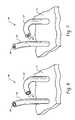
- FIG. 1is a cross sectional view of a releasable fastening system of a first embodiment
- FIG. 2is a cross sectional view of the releasable fastening system of FIG. 1 , wherein the releasable fastening system is engaged;
- FIG. 3is a cross sectional view of the releasable fastening system of FIG. 1 , wherein the releasable fastening system is disengaged;
- FIG. 4is a cross sectional view of an engaged releasable fastener system in accordance with another embodiment
- FIG. 5is a cross sectional view of the engaged releasable fastener system, wherein a loop material and a plurality of hook elements are in a shape orientation suitable for providing the engaged releasable fastener system of FIG. 6 with a reduction in shear and/or pull-off forces;
- FIG. 6is a perspective view of a hybrid hook element comprised of a fiber and sleeve, and support;
- FIG. 7is a perspective view of a hybrid hook element comprised of a fiber and sleeve, and support, in accordance with another embodiment
- FIGS. 8A and 8Bare cross sectional views of a retractable hook element
- FIG. 9Ais a cross sectional view of hook element in accordance with another embodiment and FIG. 9B is an enlarged perpective view of hook element.
- a releasable fastener systemcomprises a loop portion 12 and a hook portion 14 .
- the loop portion 12includes a support 16 and a loop material 18 disposed on one side thereof whereas the hook portion 14 includes a support 20 and a plurality of closely spaced upstanding hook elements 22 extending from one side thereof.
- the hook elements 22generally comprise or incorporate a fiber, coating, or sheath fabricated from a shape memory alloy, or a fiber, coating, or sheath (i.e., sleeve) of superelastic shape memory alloy.
- the term “fiber”refers to and is interchangeable with a filament or a wire, which fiber may comprise a single strand or multiple strands.
- the shape memory alloyprovides the hook element 22 with a shape changing capability, a yield strength changing capability, and/or a flexural modulus property change capability to the hook elements 22 , as will be described in greater detail.
- an activation device 24Coupled to and in operative communication with the hook elements 22 is an activation device 24 .
- the activation device 24provides a thermal activation signal to the hook elements 22 to cause a change in the shape orientation, yield strength, and/or flexural modulus properties of the hook elements 22 .
- the change in shape orientation, yield strength and/or flexural modulus propertygenerally remains for the duration of the applied thermal activation signal.
- the hook elements 22Upon discontinuation of the thermal activation signal, the hook elements 22 revert to an unpowered state.
- the illustrated releasable fastener system 10is exemplary only and is not intended to be limited to any particular shape, size, configuration, number or shape of hook elements 22 , shape of loop material 18 , or the like. Moreover, the orientation of each hook element may be randomly arranged on the support or may be aligned in the same direction (as shown in FIG. 1 ).
- the two portions 12 , 14are pressed together to create a joint that is relatively strong in shear and/or pull-off directions, and weak in a peel direction.
- the hook elements 22become engaged with the loop material 18 and the close spacing of the hook elements 22 resist substantial lateral movement when subjected to shearing forces in the plane of engagement.
- the engaged jointis subjected to a force substantially perpendicular to this plane, (i.e., pull-off forces)
- the hook elements 22resist substantial separation of the two portions 12 , 14 .
- the hook elements 22when the hook elements 22 are subjected to a peeling force, the hook elements 22 can become more readily disengaged from the loop material 18 , thereby separating the hook portion 12 from the loop portion 14 . It should be noted that separating the two portions 12 , 14 using the peeling force generally requires that one or both of the supports forming the hook portion and loop portion to be flexible.
- the shape orientation, yield strength, and/or flexural modulus properties of the hook elements 22are altered upon receipt of the thermal activation signal from the activation device 24 to provide a remote releasing mechanism of the engaged joint. That is, the change in shape orientation, yield strength, and/or flexural modulus of the hook elements reduces the shearing forces in the plane of engagement, and/or reduces the pull off forces perpendicular to the plane of engagement.
- the reduction in pull off forcesis generally expected to be greater than the reduction in shear forces. For example, as shown in FIGS.
- the plurality of hook elementscan have inverted J-shaped orientations that are changed, upon demand, to substantially straightened shape orientations upon receiving the thermal activation signal from the activation device 24 .
- the substantially straightened shape relative to the J-shaped orientationprovides the joint with marked reductions in shear and/or pull-off forces.
- a reduction in shear and/or pull off forcescan be observed by changing the yield strength, and/or flexural modulus of the hook elements.
- the change in yield strength and/or flexural modulus propertiescan be made independently, or in combination with the change in shape orientation. For example, changing the flexural modulus properties of the hook elements to provide an increase in flexibility will reduce the shear and/or pull-off forces.
- changing the flexural modulus properties of the hook elements to decrease flexibilityi.e., increase stiffness
- changing the yield strength properties of the hook elements to increase the yield strengthcan be used to increase the shear and pull-off forces when engaged. In both cases, the holding force is increased, thereby providing a stronger joint.
- Shape memory alloystypically exist in several different temperature-dependent phases. The most commonly utilized of these phases are the so-called martensite and austenite phases. In the following discussion, the martensite phase generally refers to the more deformable, lower temperature phase whereas the austenite phase generally refers to the more rigid, higher temperature phase.
- austenite start temperatureA s
- austenite finish temperatureA f
- the shape memory alloyWhen the shape memory alloy is in the austenite phase and is cooled, it begins to change into the martensite phase, and the temperature at which this phenomenon starts is referred to as the martensite start temperature (M s ).
- the temperature at which martensite finishes transforming to martensiteis called the martensite finish temperature (M f ).
- the shape memory alloysare soft and easily deformable in their martensitic phase and are hard, stiff, and/or rigid in the austenitic phase.
- the releasable fastener systemcan be configured with a variety of capabilities.
- the hook elementsmay be fabricated from shape memory alloys that exhibit an austenite phase at an ambient environmental temperature in which the releasable fastener system is disposed and with a shape effective for engagement with the loop material. Thermal activation would thus require cooling the hook elements to a temperature below the austenite temperature to the martensite phase transformation temperature to cause disengagement.
- the hook elementsmay be fabricated and engaged with the loop portion in a martensite phase, wherein the martensite phase transformation is at or above the ambient environmental conditions in which the releasable fastener system is disposed.
- heating the hook elements to an austenite finish temperaturewould, given the proper materials processing, preferably cause the hook elements to straighten and cause disengagement.
- Shape memory alloyscan exhibit a one-way shape memory effect, an intrinsic two-way effect, or an extrinsic two-way shape memory effect depending on the alloy composition and processing history.
- Annealed shape memory alloystypically only exhibit the one-way shape memory effect. Sufficient heating subsequent to low-temperature deformation of the shape memory material will induce the martensite to austenite type transition, and the material will recover the original, annealed shape. Hence, one-way shape memory effects are only observed upon heating. Hook elements formed from shape memory alloy compositions that exhibit one-way memory effects do not automatically reform, and depending on the hook element design, will likely require an external mechanical force to reform the shape orientation that was previously suitable for engagement with the loop portion.
- Intrinsic and extrinsic two-way shape memory materialsare characterized by a shape transition both upon heating from the martensite phase to the austenite phase, as well as an additional shape transition upon cooling from the martensite phase back to the austenite phase. Hook elements that exhibit an intrinsic shape memory effect are fabricated from a shape memory alloy composition that will automatically reform themselves as a result of the above noted phase transformations. Intrinsic two-way shape memory behavior must be induced in the shape memory material through processing. Such procedures include extreme deformation of the material while in the martensite phase, heating-cooling under constraint or load, or surface modification such as laser annealing, polishing, or shot-peening.
- hook elements that exhibit the extrinsic two-way shape memory effectsare composite or multi-component materials that combine a shape memory alloy composition that exhibits a one-way effect with another element that provides a restoring force to reform the hook-like shape.
- the hook elements 22are fabricated from shape memory alloys that exhibit one-way shape memory effects.
- the hook elementsare fixedly attached to support 20 or may be integrally formed with the support 20 .
- the mechanical engagement of the hook portion 14 with the loop portion 12(as shown in FIG. 1 ) can be achieved by interaction of the hook elements 22 with the loop material 18 or through physical deformation of suitably arranged hook elements 22 during the face-to-face engagement. That is, each hook element 22 preferably maintains a shape orientation conducive for contact engagement with the loop material 18 . Physical deformation may also be employed to provide a shape orientation suitable for the engagement with the loop portion 18 .
- FIG. 2illustrates the hook element 22 in one such exemplary engagement position.
- the shape memory alloyis preferably in the martensite phase.
- the hook elements 22change to substantially straightened shape orientations as shown in FIG. 3 .
- a marked reduction in shear and pull-off forcescan be provided to the releasable fastener system 10 through application of a thermal activation signal.
- the marked reduction in shear and pull-off forcesmay also be effected by changes in the yield strength, and/or flexural modulus properties of the hook elements 22 .
- the shape memory alloy hook elementsare coated with a polymer, an elastomer, or a shape memory polymer to increase the stiffness of the hook elements and as such, its hold force at martensite temperature states.
- the applied polymer or elastomerserves to maintain a nearly constant strain level to the hook element.
- the polymer or elastomeris preferably selected to provide reversible strains to the hook elements such that upon cooling, the shape memory alloy transforms to the martensite phase, and the elastic strains extant in the polymer or elastomer coating are sufficient to reset the shape of the shape memory alloy element back into the hook shape that existed prior to release.
- a shape memory polymerSimilar to the behavior of a shape memory alloy, when the temperature is raised through its transition temperature, a shape memory polymer also undergoes a rapid and reversible decrease in yield strength/flexural modulus and change in shape orientation.
- a shape memory alloyBy coating a shape memory alloy with a shape memory polymer whose transition temperature is below that of the shape memory alloy, it is also possible to reversibly form and reform the hook shape.
- the straightened shapeis set by the shape memory alloy above its (higher) transition temperature while the (reformed) hook shape is set by the shape memory polymer above its (lower) transition temperature. Heating therefore causes hook release and as the straightened hook is cooled below the higher temperature, the shape orientation defined by the shape memory alloy reestablishes the hook orientation.
- the superelastic properties of the shape memory alloyscan be employed.
- Superelastic behaviorresults if the shape memory alloy is deformed at a temperature that is slightly above its transformation temperatures. The superelastic effect is caused by a stress-induced formation of some martensite above its normal temperature. Because it has been formed above its normal temperature, the martensite reverts immediately to an undeformed austenite as soon as the stress is removed. This process provides a very springy, “rubberlike” elasticity in these alloys.
- the hook elements 22are fabricated from a selected shape memory alloy composition that maintains the austenite phase at environmental temperature conditions in which the fastener is to be employed.
- the shape of the hook elements 22 in the austenite phasewould be suitable for engagement with the loop material 18 (e.g., similar to the shape shown in FIG. 2 ). Cooling the hook elements 22 to a temperature below the austenite phase (i.e., to the martensite phase) reduces the yield strength and/or the flexural modulus of the hook elements, hence reducing the shear and pull off forces relative to those present while the hook elements 22 are engaged with the loop material 18 while in the austenite phase.
- the shape memory alloy compositioncan be selected to exhibit an austenite phase at about room temperature. Lowering the temperature of the hook elements 22 below room temperature would cause the hook elements 22 to transform from the stiffer austenite phase to the weaker martensite phase, thereby permitting separation in the shear and/or pull off directions at significantly lower force levels.
- the hook elements 22 and/or loop material 18are fabricated from shape memory alloys that preferably exhibit two-way shape memory effects.
- both the hook and loop elementsreceive processing (“training”) suitable to produce a reversible shape change that occurs as the hook elements (and/or loop material) transition from the martensite phase to the austenite phase, and vice versa.
- the reversible shape changecan be manipulated back and forth between shape orientations suitable for engagement and disengagement.
- both the hook elements 22 and the loop material 18are selected to have a spiral shape orientation, which when pressed together result in an engagement that is relatively strong in shear and pull-off forces and weak in peel forces.
- the hook elements and the loop materialare mated together in a straightened shape orientation ( FIG. 5 ), and then allowed to cool to the spiral shape orientation ( FIG. 4 ).
- the loop material 18 in this embodimentcan be made active upon receipt of an appropriate thermal activation signal. Thermally activating the hook elements 22 and/or loop material 18 can cause a change in shape orientation, yield strength, and/or flexural modulus to provide a marked reduction in shear and pull-off forces required for separation.
- the superelastic properties of the shape memory alloycan be employed in a manner similar to that previously described, except that processing to enable two-way behavior in the loop and/or hook elements is not required.
- the spiralsmaintain the spiral shape orientation at the environmental temperature conditions in which the fastener is disposed. Lowering the temperature of the shape memory alloy spirals from the environmental temperature condition (i.e., an austenite phase temperature) to a martensite phase temperature condition causes a significant decrease in the yield strength and/or flexural modulus properties of the spiral. As a result, a marked reduction in shear and pull-off forces is observed.
- the reduction in temperature from the austenite temperature condition to the martensite temperature conditioncan be made to a selected one of the hook portion 14 and loop portion 12 , or to both portions 12 , 14 to achieve the reduction in shear and pull-off forces.
- Applying the thermal activation signal(in this embodiment, the thermal activation signal lowers the temperature) to both portions 12 , 14 will cause a further reduction in shear and pull off forces relative to applying the activation signal to a selected one of the hook portion 14 and loop portion 12 .
- FIG. 6illustrates a hybrid shape memory alloy hook element 30 attached to a support 31 in accordance with another embodiment.
- the hook element 30generally comprises a shape memory alloy sleeve 32 coupled to a flexible, elastic core material 34 .
- the sleeve and core materialsneed not be bonded together to provide robust operation.
- Suitable flexible core materialsinclude shape memory alloys with compositions chosen so that they exhibit superelasticity in the temperature range where the releasable attachment is to be used (i.e. a superelastic material), more commonly available but highly elastic materials such as spring steels, shape memory polymers, elastomers, or other highly elastic fibers or filaments such as carbon fibers.
- the core materialis a superelastic material, such as Ni x Ti 1 ⁇ x , wherein x is about 56%.
- the hook element 30is preferably in a shape orientation suitable for engagement with a loop material 18 (as shown in FIG. 1 ). Applying a thermal activation signal (powered state) to the shape memory alloy causes a change in the shape orientation, yield strength, and/or flexural modulus property of the hook element 30 .
- the selected shape memory alloy composition and/or suitable processingmay provide a one-way shape memory effect or a two-way shape memory effect depending on the desired application.
- the elasticity of the core materialmay be utilized to enable extrinsic two-way behavior to the hook in order to allow it to return to a shape orientation suitable for re-engagement.
- FIG. 7illustrates a hybrid shape memory alloy hook element 40 attached to a support 41 .
- the hook element 40comprises a sleeve 42 coupled to a shape memory alloy core 44 .
- the shape memory alloy core 44is preferably a wire or fiber fabricated from the shape memory alloy.
- the sleeve and core materialsneed not be bonded together to provide robust operation.
- Suitable sleeve materialsagain include shape memory alloys with compositions chosen so that they exhibit superelasticity in the temperature range where the releasable attachment is to be used (i.e. a superelastic material), more commonly available but highly elastic materials such as spring steel, shape memory polymers, elastomers, or other highly elastic fibers or filaments such as carbon fibers.
- the shape memory alloy core 34preferably has a straightened or substantially straightened shape orientation.
- hook element 40will preferably revert to a shape configuration suitable for engagement with the loop material.
- Applying a thermal activation signal (powered state) to the hook element 40 to obtain the martensite or austenite shape transformationscauses a change in the shape orientation, yield strength, and/or flexural modulus property of the hook element 40 .
- FIGS. 8A and 8Billustrate a retractable hook element 50 in accordance with another embodiment.
- a shape memory alloy fiber 52is disposed in a rigid and inflexible sleeve 54 , wherein a change in shape orientation of the shape memory alloy fiber comprises a change in a length dimension.
- Suitable rigid sleeve materialsinclude, but are not limited to, metals, such as steels, aluminum and aluminum alloys, brass, or copper and copper alloys, or stiff polymer materials such as poly(ethylene terephthalate), poly(methyl methacrylate), poly(vinylidene fluoride), polycarbonate, polyamide (nylon), polystyrene, rigid poly-vinyl chloride (PVC), polyimide, and similar high modulus materials.
- An elastic hook 56is attached to an end of the shape memory fiber 52 .
- Material for the elastic hook 56is preferably selected from materials such as superelastic shape memory alloys, spring steels, or elastomers such as polyethylene, silicone, polybutadiene, neoprene, nitrile, and butyl and fluorinated rubbers.
- the other end of the fiberis attached to a support 58 .
- the shape memory fiber 52is fabricated from a shape memory alloy composition such that in the martensite phase, a length of the shape memory alloy fiber extends about the length of the sleeve. As such, in the martensite phase, the elastic hook 56 extends from the sleeve and is engaged with the loop material 18 .
- the shape memory alloy fiber 52contracts (i.e., a decrease in the length dimension is observed) and retracts a portion of the elastic hook 56 into the sleeve 54 , thereby disengaging the elastic hook 56 from the loop material 18 and providing a reduction in shear and pull forces.
- a plurality of elastic hooks 56may be attached to a single shape memory fiber 52 and sleeve 54 providing multiple tines for releasable engagement with the loop material 18 .
- the shape memory alloy fiberwill transform back to the martensite phase, and the elastic energy stored in the hook will in turn stretch the shape memory alloy fiber, resetting the hook mechanism for re-engagement with the loop portion.
- the releasable fastener system 60comprises a hook portion 62 comprising a support 64 and a plurality of hook elements 66 disposed on a surface thereon, wherein each of the plurality of hook elements 66 comprises one or more shape memory alloy fibers 68 coupled to an elastic element 70 ; and a thermal activation device 24 coupled to the plurality of hook elements 66 , the thermal activation device 24 being operable to selectively provide a thermal activation signal to the shape memory alloy fiber and change a shape orientation, a yield strength and/or flexural modulus property, or a combination of these properties of the plurality of hook elements to reduce a shear force and/or a pull-off force of an engaged hook and loop portion 12 .
- the number of elastic elements coupled to the single shape memory alloy fibermay be equal to or greater than one depending on the desired application.
- a shape memory alloy elementcan be combined with an elastic portion to produce a hook element that exhibits, for example, a two-way behavior.
- a straight shape memory alloy fiber in the martensite phasemight be adhered, glued, welded, or otherwise attached to a stretched coil or J-shaped elastic portion.
- This elastic portioncould be comprised of a number of materials, including but not limited to, superelastic shape memory alloys, spring or other steels, or other elastic plastic or polymer materials. After attaching the elastic portion to the shape memory alloy fiber, the stretched, elastic portion is allowed to relax, and in the process deforms the attached martensite shape memory alloy fiber.
- shape memory alloy fiberUpon heating, the shape memory alloy fiber will transform to the austenite phase, and cause the coiled or J-shaped elastic portion to straighten. Conversely, a shape memory alloy fiber that has been pre-stretched while in the martensite phase could be attached to a straight elastic portion. Depending on the geometry of attachment and the initial shape orientation of the elastic portion, upon heating and transforming the shape memory alloy fiber to the austenite phase, the combined hook element will change shape to a spiral or other hook-like shape suitable for engagement.
- the superelasticity property of shape memory alloyscan also be utilized to provide release upon cooling. For instance, a superelastic shape memory alloy fiber in the austenite phase that has been pre-shaped to take on a hook geometry can be stretched and bonded to an initially straight elastic element.
- the superelastic shape memory alloy fiberUpon cooling, the superelastic shape memory alloy fiber will transform from the austenite to the easily deformable martensite phase, and the elastic portion will deform the shape memory alloy fiber, causing the combined hook element to straighten or take on geometry suitable to reduce the pull-off and/or shear forces.
- Other geometrical possibilitiesinclude multiple elastic portions attached symmetrically or asymmetrically to the shape memory alloy fiber, in order to bias the shape change to occur between optimal hook (hold) and straight (release) shapes.
- the temperature at which the shape memory alloy remembers its high temperature form when heatedcan be adjusted by slight changes in the composition of the alloy and through heat treatment. In nickel-titanium shape memory alloys, for instance, it can be changed from above about 100° C. to below about ⁇ 100° C.
- the shape recovery processoccurs over a range of just a few degrees and the start or finish of the transformation can be controlled to within a degree or two depending on the desired application and alloy composition.
- the mechanical properties of the shape memory alloyvary greatly over the temperature range spanning their transformation, typically providing the hook elements with shape memory effects, superelastic effects, and high damping capacity.
- Suitable shape memory alloy materials for fabricating the hook elements and/or sheathinclude, but are not intended to be limited to, nickel-titanium based alloys, indium-titanium based alloys, nickel-aluminum based alloys, nickel-gallium based alloys, copper based alloys (e.g., copper-zinc alloys, copper-aluminum alloys, copper-gold, and copper-tin alloys), gold-cadmium based alloys, silver-cadmium based alloys, indium-cadmium based alloys, manganese-copper based alloys, iron-platinum based alloys, iron-palladium based alloys, and the like.
- nickel-titanium based alloysindium-titanium based alloys, nickel-aluminum based alloys, nickel-gallium based alloys, copper based alloys (e.g., copper-zinc alloys, copper-aluminum alloys, copper-gold,
- the alloyscan be binary, ternary, or any higher order so long as the alloy composition exhibits a shape memory effect, e.g., change in shape orientation, changes in yield strength, and/or flexural modulus properties, damping capacity, and the like.
- a preferred shape memory alloyis a nickel-titanium based alloy commercially available under the trademark NITINOL from Shape Memory Applications, Inc.
- the shape memory alloy fibersmay be formed integrally with support, or more preferably, may be attached directly to the support.
- an adhesivecan be applied (e.g., silver-doped epoxy) to the substrate and the shape memory alloy hook elements can be mechanically pressed into the adhesive.
- vapor grown shape memory alloy fiberscan be deposited directly from a gas phase onto a support.
- Suitable support materialsinclude, but are not intended to be limited to, metals (such as superelastic NiTi) plastics (such as polyethylene filaments) or fabrics.
- the thickness of the shape memory alloy fiberis chosen to provide resiliency and flexibility to the hook elements for those applications requiring a change in shape orientation, yield strength, and/or flexural modulus.
- the thicknessis preferably suitable for providing an effective length change at sufficient force levels to achieve actuation.
- the thickness of the shape memory alloy fibershould also be of a thickness effective to provide the desired shape memory effect.
- shape of the fiber depicted in the Figuresis generally cylindrical, other shapes are suitable such as, for example, fibers having a cross-sectional shape of an oval, a cross, a square, a rectangle, and the like. As such, the fibers 23 are not intended to be limited to any particular shape.
- the spacing between adjacent hook elementsis in an amount effective to provide the hook portion with sufficient shear and/or pull off resistance desired for the particular application during engagement with the loop portion.
- the amount of shear and/or pull-off force required for effective engagementcan vary significantly. Generally, the closer the spacing and the greater amount of the hook elements employed will result in increased shear and/or pull off forces upon engagement.
- the hook elementspreferably have a shape configured to become engaged with the loop material upon pressing contact of the loop portion with the hook portion, and vice versa. As such, the hook elements are not intended to be limited to any particular shape.
- the hook elementscan have an inverted J-shaped orientation, a mushroom shape, a knob shape, a multi-tined anchor, T-shape, spirals, or any other form of a hook-like element used for separable hook and loop fasteners.
- Such elementsare referred to herein as “hook-like”, “hook-type”, or “hook” elements whether or not they are in the shape of a hook.
- the loop materialmay comprise a plurality of loops or pile, a shape complementary to the hook element (e.g., a key and lock type engagement), or any other form of a loop-like element used for separable hook and loop fasteners.
- the arrays of hook elements of various geometries and/or loop material on the respective supportsare to be so arranged and sufficiently dense such that the action of pressing the two portions together results in the mechanical engagement of the hook elements with the loop material creating a joint that is strong in shear and pull-off forces, and relatively weak in peel.
- Remote disengagement of the two portionsis effected variously by raising the temperature of the shape memory alloy above its transformation temperature causing the hook elements to straighten (e.g. in those examples in which the shape memory property of the shape memory alloy is employed), and/or by lowering the temperature of the shape memory alloy to effect a switch from the stiffer austenite to the weaker martensite phase (e.g. in those examples in which the superelasticity property of shape memory alloys is employed).
- changing the shape orientation, yield strength, and/or flexural modulus properties of the hook elementscan be used to provide on-demand remote engagement and disengagement of joints/attachments.
- the loop materialgenerally comprises a random looped pattern or pile of a material.
- the loop materialis often referred by such terms as the “soft”, the “fuzzy”, the “pile”, the “female”, or the “carpet”.
- Suitable loop materialsare commercially available under the trademark VELCRO from the Velcro Industries B.V.
- Materials suitable for manufacturing the loop materialinclude thermoplastics such as polypropylene, polyethylene, polyamide, polyester, polystyrene, polyvinyl chloride, acetal, acrylic, polycarbonate, polyphenylene oxide, polyurethane, polysulfone, and the like.
- the loop material 18may be integrated with the support or may be attached to the support.
- the loop materialcan be fabricated from the same shape changing, yield strength changing, and/or flexural modulus changing materials employed for the hook elements as previously discussed. As such, instead of being passive, the loop material can be made active upon receipt of an activation signal.
- the supports for the various loop and hook portionsmay be rigid or flexible depending on the intended application.
- Suitable materials for fabricating the supportinclude plastics, fabrics, metals, and the like.
- suitable plasticsinclude thermoplastics such as for example polypropylene, polyethylene, polyamide, polyester, polystyrene, polyvinyl chloride, acetal, acrylic, polycarbonate, polyphenylene oxide, polyurethane, polysulfone, and other like thermoplastic polymers.
- An adhesivemay be applied to the backside surface of the support (the surface free from the hook elements 22 or loop material) for application of the releasable fastener system to an apparatus or structure.
- the releasable fastener systemmay be secured to an apparatus or structure by bolts, by welding, or any other mechanical securement means.
- both supportscould be fabricated from a rigid or inflexible material in view of the remote releasing capability provided.
- Traditional hook and loop fastenerstypically require at least one support to be flexible so that a peeling force can be applied for separation of the hook and loop fastener.
- the supportmay also comprise the activation device for providing the thermal activating signal to the hook elements and/or loop material depending on the particular design of the releasable fastener system.
- the supportmay be a resistance type-heating block to provide a thermal energy signal sufficient to cause a shape change and/or change in yield strength, or flexural modulus properties.
- the shape memory material coated or deposited onto the fibersmay be activated by any suitable means, i.e., a thermal activation signal, preferably a means for subjecting the material to a temperature change above, or below, a transition temperature.
- a thermal activation signalpreferably a means for subjecting the material to a temperature change above, or below, a transition temperature.
- heatmay be supplied using hot gas (e.g. air), steam, or electrical current.
- the activation meansmay, for example, be in the form of a heated room or enclosure, or an iron for supplying heat, a hot air blower or jet, means for passing an electric current through, or inducing an electrical current in (e.g. by magnetic or microwave interaction), the shape memory material (or through or in an element in thermal contact therewith).
- heatmay be extracted by using cold gas, a thermoelectric element, or evaporation of a refrigerant.
- the activation meansmay, for example, be in the form of a cool room or enclosure, a cooling probe having a cooled tip, a control signal to a thermoelectric element, a cold air blower or jet, or means for introducing a refrigerant (such a liquid nitrogen) to at least the vicinity of the shape memory material.
- Shape setting or training of the hook elementscan be made by constraining to the hook element on a mandrel or fixture of the desired shape and applying an appropriate heat treatment.
- the shapecan also be imparted by surface treatments such as application of high-energy beams from ion or laser sources or other mechanical means such as by shot peening or polishing.
- the heat treatment methods used to set the shape in both shape memory and superelastic forms of the shape memory alloyare similar.
- the heat treatment parameters chosen to set both the shape and the properties of the hook elementsusually need to be determined experimentally. For example, shape setting nickel titanium shape memory alloys generally requires a temperature greater than about 400° C. for a period of time greater than about 1 minute.
- Rapid cooling of some formis preferred via a water quench or rapid air cool (if both the parts and the fixture are small). Higher heat treatment times and temperatures will increase the actuation temperature of the part and often gives a sharper thermal response (in the case of shape memory elements).
- the shape memory alloymay be cooled below M f and bent to a desired shape. The hook element is then heated to a temperature above A f and allowed freely to take its austenite shape. The procedure is repeated about 20 to about 30 times, which completes the training. The sample now assumes its programmed shape upon cooling under M f and to another shape when heated above A f .
- the hook elementis bent just above M s to produce the preferred variants of stress-induced martensite and then cooled below the M f temperature. Upon subsequent heating above the A f temperature, the specimen takes its original austenitic shape. This procedure is repeated about 20 to about 30 times.
- the shape memory materialmay be activated by any suitable means, preferably a means for subjecting the material to a temperature change above, or below, a transition temperature.
- heatmay be supplied using hot gas (e.g. air), steam, or electrical current.
- the activation meansmay, for example, be in the form of a heated room or enclosure, an iron for supplying heat, a hot air blower or jet, means for passing an electric current through, or inducing an electrical current in (e.g. by magnetic or microwave interaction), the shape memory material (or through or in an element in thermal contact therewith).
- heatmay be extracted by using cold gas, or evaporation of a refrigerant.
- the activation meansmay, for example, be in the form of a cool room or enclosure, a cooling probe having a cooled tip, a control signal to a thermoelectric unit, a cold air blower or jet, or means for introducing a refrigerant (such as liquid nitrogen) to at least the vicinity of the shape memory material.
- a refrigerantsuch as liquid nitrogen
- a hook portionwas fabricated from a nickel-titanium (NiTi) shape memory alloy.
- NiTinickel-titanium
- a 200 ⁇ m thick NiTi shape memory alloy wire with a austenite finish transition temperature of 70° C.was woven into a metallic mesh (approximately 1 millimeter mesh spacing) and around a ceramic rod mandrel of radius 1.25 millimeter (mm).
- the rodwas removed and the shape memory alloy wire loops were fixed to the back of the mesh using an epoxy. After the epoxy was cured, the loops were cut near the base of one side of each loop to form an array of hook elements.
- a 15 to 20 watt heating elementwas affixed to the back of the metal mesh.
- the hook portionwas pressed in face-to-face engagement with a loop portion consisting of a Velcro® loop material commercially available from the Velcro Corporation, resulting in a mechanical engagement resistant to shear and pull off forces, and weak in peel forces.
- a loop portionconsisting of a Velcro® loop material commercially available from the Velcro Corporation
- Force levelswere found to be comparable to commercial Velcro®, at about 4 to about 5 pounds per square inch (psi) pull-off force prior to activation (heating) and 0.005 psi after heating.
- Re-engagement with the loop surfacewas accomplished by applying sufficient force between the parts to re-deform the shape memory hook elements and entangle them in the loop material. The process was found to be highly repeatable, having been cycled >50 times.
Landscapes
- Engineering & Computer Science (AREA)
- General Engineering & Computer Science (AREA)
- Chemical & Material Sciences (AREA)
- Materials Engineering (AREA)
- Mechanical Engineering (AREA)
- Slide Fasteners, Snap Fasteners, And Hook Fasteners (AREA)
Abstract
Description
Claims (11)
Priority Applications (3)
| Application Number | Priority Date | Filing Date | Title |
|---|---|---|---|
| US10/305,375US7146690B2 (en) | 2002-10-19 | 2002-11-26 | Releasable fastener system |
| EP03026259AEP1424023B1 (en) | 2002-11-26 | 2003-11-14 | Releasable fastener system |
| DE60323317TDE60323317D1 (en) | 2002-11-26 | 2003-11-14 | Detachable fastening device |
Applications Claiming Priority (2)
| Application Number | Priority Date | Filing Date | Title |
|---|---|---|---|
| US10/273,691US7200902B2 (en) | 2002-10-19 | 2002-10-19 | Releasable fastener system |
| US10/305,375US7146690B2 (en) | 2002-10-19 | 2002-11-26 | Releasable fastener system |
Related Parent Applications (1)
| Application Number | Title | Priority Date | Filing Date |
|---|---|---|---|
| US10/273,691Continuation-In-PartUS7200902B2 (en) | 2002-10-19 | 2002-10-19 | Releasable fastener system |
Publications (2)
| Publication Number | Publication Date |
|---|---|
| US20040074062A1 US20040074062A1 (en) | 2004-04-22 |
| US7146690B2true US7146690B2 (en) | 2006-12-12 |
Family
ID=32298051
Family Applications (1)
| Application Number | Title | Priority Date | Filing Date |
|---|---|---|---|
| US10/305,375Expired - LifetimeUS7146690B2 (en) | 2002-10-19 | 2002-11-26 | Releasable fastener system |
Country Status (3)
| Country | Link |
|---|---|
| US (1) | US7146690B2 (en) |
| EP (1) | EP1424023B1 (en) |
| DE (1) | DE60323317D1 (en) |
Cited By (12)
| Publication number | Priority date | Publication date | Assignee | Title |
|---|---|---|---|---|
| US20080282696A1 (en)* | 2007-05-15 | 2008-11-20 | Konica Minolta Opto, Inc. | Drive apparatus and lens drive apparatus |
| US20090223019A1 (en)* | 2008-03-10 | 2009-09-10 | Bigfish Consulting Llc | Apparatus for wrapping around one or more target objects for gripping, as a hanging structure and/or to provide an extension |
| US20120266417A1 (en)* | 2008-03-19 | 2012-10-25 | GM Global Technology Operations LLC | Active material based fasteners including cable ties and twist ties |
| US8608890B2 (en) | 2010-11-11 | 2013-12-17 | Spirit Aerosystems, Inc. | Reconfigurable shape memory polymer tooling supports |
| US8734703B2 (en) | 2010-11-11 | 2014-05-27 | Spirit Aerosystems, Inc. | Methods and systems for fabricating composite parts using a SMP apparatus as a rigid lay-up tool and bladder |
| US8815145B2 (en) | 2010-11-11 | 2014-08-26 | Spirit Aerosystems, Inc. | Methods and systems for fabricating composite stiffeners with a rigid/malleable SMP apparatus |
| US8877114B2 (en) | 2010-11-11 | 2014-11-04 | Spirit Aerosystems, Inc. | Method for removing a SMP apparatus from a cured composite part |
| US20150068013A1 (en)* | 2013-09-10 | 2015-03-12 | Texas Instruments Incorporated | Current, temperature or electromagnetic field actuated fasteners |
| US20180178047A1 (en)* | 2016-12-22 | 2018-06-28 | Velcro BVBA | Energy dissipating touch fastener links |
| US10844922B2 (en) | 2016-12-22 | 2020-11-24 | Velcro BVBA | Multi-closure energy dissipating touch fastener links |
| US11076660B2 (en)* | 2018-08-31 | 2021-08-03 | Lintec Of America, Inc. | Hook and loop artificial muscles |
| US11191680B2 (en)* | 2011-08-25 | 2021-12-07 | Microkoll, Inc. | Apparatus and methods for adhesion |
Families Citing this family (25)
| Publication number | Priority date | Publication date | Assignee | Title |
|---|---|---|---|---|
| US7207946B2 (en)* | 2002-05-09 | 2007-04-24 | Spiration, Inc. | Automated provision of information related to air evacuation from a chest cavity |
| US7146690B2 (en) | 2002-10-19 | 2006-12-12 | General Motors Corporation | Releasable fastener system |
| US7032282B2 (en) | 2002-10-19 | 2006-04-25 | General Motors Corporation | Releasable fastener system |
| US6973701B2 (en)* | 2002-10-19 | 2005-12-13 | General Motors Corporation | Releasable fastening system based on ionic polymer metal composites and method of use |
| US7140081B2 (en)* | 2002-10-19 | 2006-11-28 | General Motors Corporation | Releasable fastener system |
| US7013536B2 (en) | 2002-10-19 | 2006-03-21 | General Motors Corporation | Releasable fastener systems and processes |
| JP4015983B2 (en)* | 2002-10-19 | 2007-11-28 | ゼネラル・モーターズ・コーポレーション | Magnetorheological nanocomposite elastomer for releasable accessories |
| US7013538B2 (en) | 2002-10-19 | 2006-03-21 | General Motors Corporation | Electroactive polymer releasable fastening system and method of use |
| US7308738B2 (en)* | 2002-10-19 | 2007-12-18 | General Motors Corporation | Releasable fastener systems and processes |
| US6983517B2 (en)* | 2002-10-19 | 2006-01-10 | General Motors Corporation | Releasable fastener system |
| US6944920B2 (en)* | 2002-10-19 | 2005-09-20 | General Motors Corporation | Electrostatically releasable fastening system and method of use |
| US7219113B2 (en)* | 2003-09-26 | 2007-05-15 | International Business Machines Corporation | Pseudo-random binary sequence checker with automatic synchronization |
| US20050246873A1 (en)* | 2003-11-07 | 2005-11-10 | Tachauer Ernesto S | Active fasteners |
| US20060261109A1 (en)* | 2005-05-18 | 2006-11-23 | Browne Alan L | Cargo container including an active material based releasable fastener system |
| GB2431720B (en)* | 2005-10-26 | 2007-12-19 | Rolls Royce Plc | Actuator |
| US7581706B2 (en)* | 2006-06-26 | 2009-09-01 | Lear Corporation | Shape memory alloy (SMA) system |
| DE102006050365A1 (en)* | 2006-10-25 | 2008-04-30 | MAX-PLANCK-Gesellschaft zur Förderung der Wissenschaften e.V. | Structured surface with switchable adhesion |
| US7976924B2 (en)* | 2007-02-03 | 2011-07-12 | Raytheon Company | Active garment materials |
| WO2009151678A1 (en)* | 2008-03-11 | 2009-12-17 | Massachusetts Institute Of Technology | Stimuli-responsive surfaces |
| US8540297B2 (en)* | 2008-09-15 | 2013-09-24 | GM Global Technology Operations LLC | Manipulating center console components utilizing active material actuation |
| WO2013141878A1 (en)* | 2012-03-23 | 2013-09-26 | Crucible Intellectual Property Llc | Fasteners of bulk amorphous alloy |
| US20160052145A1 (en)* | 2014-08-19 | 2016-02-25 | GM Global Technology Operations LLC | Conformable holding device |
| DE102015219756B4 (en) | 2015-10-13 | 2024-11-07 | Bayerische Motoren Werke Aktiengesellschaft | Connection system and method for connecting at least two components |
| KR101973237B1 (en)* | 2016-09-08 | 2019-04-26 | 경희대학교 산학협력단 | Samrt opening and closing apparatus |
| CN116989040B (en)* | 2023-06-30 | 2025-09-19 | 浙江大学 | Labyrinth interlocking intelligent structure based on 4D printing and locking method thereof |
Citations (105)
| Publication number | Priority date | Publication date | Assignee | Title |
|---|---|---|---|---|
| US2717437A (en) | 1951-10-22 | 1955-09-13 | Velcro Sa Soulie | Velvet type fabric and method of producing same |
| US2994117A (en) | 1958-01-31 | 1961-08-01 | Mcmullin Harold Breniman | Opening closure means |
| US3101517A (en) | 1960-11-28 | 1963-08-27 | Fox Marvin | Fastener |
| US3128514A (en) | 1959-04-03 | 1964-04-14 | Parker Pen Co | Writing instrument releasable securing means |
| US3138749A (en) | 1962-03-05 | 1964-06-23 | George R Stibitz | Incremental feed mechanisms |
| US3176364A (en) | 1959-10-06 | 1965-04-06 | Dritz Arthur | Separable fastener |
| US3292019A (en) | 1963-11-01 | 1966-12-13 | Bendix Corp | Transducer |
| US3365757A (en) | 1964-10-13 | 1968-01-30 | Billarant Jean | Flexible band fitted with hooked elements of the filament type |
| US3469289A (en)* | 1969-02-06 | 1969-09-30 | Nasa | Quick release hook tape |
| US3490107A (en)* | 1967-10-16 | 1970-01-20 | George C Brumlik | Hook-like fastening assembly |
| US3808648A (en) | 1970-12-04 | 1974-05-07 | Velcro France | Separable fastening sheet |
| US4169303A (en) | 1976-11-24 | 1979-10-02 | Lemelson Jerome H | Fastening materials |
| US4382243A (en) | 1980-08-20 | 1983-05-03 | Robert Bosch Gmbh | Electromagnetic positioning device with piezo-electric control |
| US4391147A (en) | 1980-03-19 | 1983-07-05 | Hans List | Transducer device for measuring mechanical values on hollow bodies |
| US4634636A (en) | 1983-12-13 | 1987-01-06 | Asahi Kasei Kogyo Kabushiki Kaisha | Polyacetylene composite |
| US4637944A (en) | 1985-03-19 | 1987-01-20 | Monsanto Company | Process and device for temporarily holding and releasing objects |
| US4642254A (en) | 1985-03-19 | 1987-02-10 | Monsanto Company | Process and device for temporarily holding and releasing objects |
| US4693921A (en)* | 1983-12-13 | 1987-09-15 | Aplix | Fastening tape designed to be attached to a molded article during molding, and its attaching method |
| US4752537A (en) | 1985-06-10 | 1988-06-21 | The Boeing Company | Metal matrix composite fiber reinforced weld |
| US4775310A (en) | 1984-04-16 | 1988-10-04 | Velcro Industries B.V. | Apparatus for making a separable fastener |
| US4794028A (en) | 1984-04-16 | 1988-12-27 | Velcro Industries B.V. | Method for continuously producing a multi-hook fastner member and product of the method |
| JPH01162587A (en) | 1987-12-19 | 1989-06-27 | Kawasaki Heavy Ind Ltd | Laser welding method |
| US4931344A (en)* | 1987-12-15 | 1990-06-05 | Kuraray Company, Ltd. | Fastener component |
| EP0385443A2 (en) | 1989-02-28 | 1990-09-05 | Daikin Industries, Limited | Polymer material having shape memory characteristics |
| US5037178A (en) | 1988-12-22 | 1991-08-06 | Kingston Technologies, L.P. | Amorphous memory polymer alignment device |
| US5071363A (en) | 1990-04-18 | 1991-12-10 | Minnesota Mining And Manufacturing Company | Miniature multiple conductor electrical connector |
| US5133112A (en) | 1991-04-25 | 1992-07-28 | Gomez Acevedo Hector H | Closure device |
| US5136201A (en) | 1990-04-27 | 1992-08-04 | Rockwell International Corporation | Piezoelectric robotic articulation |
| JPH04266970A (en) | 1991-02-20 | 1992-09-22 | Toyota Central Res & Dev Lab Inc | Elastic modulus-variable material |
| JPH04314446A (en) | 1990-04-06 | 1992-11-05 | Natl Res Dev Corp | Oral fluid intake apparatus |
| US5182484A (en) | 1991-06-10 | 1993-01-26 | Rockwell International Corporation | Releasing linear actuator |
| US5191166A (en) | 1991-06-10 | 1993-03-02 | Foster-Miller, Inc. | Survivability enhancement |
| US5212855A (en) | 1991-08-05 | 1993-05-25 | Mcganty Leo F | Multiple button closure-fastener |
| US5284330A (en) | 1992-06-18 | 1994-02-08 | Lord Corporation | Magnetorheological fluid devices |
| US5312456A (en) | 1991-01-31 | 1994-05-17 | Carnegie Mellon University | Micromechanical barb and method for making the same |
| US5319257A (en) | 1992-07-13 | 1994-06-07 | Martin Marietta Energy Systems, Inc. | Unitaxial constant velocity microactuator |
| US5328337A (en) | 1990-08-17 | 1994-07-12 | Kunta Norbert J | Guided vanes hydraulic power system |
| EP0673709A1 (en) | 1994-03-25 | 1995-09-27 | Fujikura Kasei Co., Ltd. | Machine tool damping apparatus |
| US5474227A (en) | 1993-06-24 | 1995-12-12 | The Idod Trust | Method of forming seamed metal tube |
| US5486676A (en) | 1994-11-14 | 1996-01-23 | General Electric Company | Coaxial single point powder feed nozzle |
| US5492534A (en) | 1990-04-02 | 1996-02-20 | Pharmetrix Corporation | Controlled release portable pump |
| US5497861A (en) | 1994-06-27 | 1996-03-12 | Brotz; Gregory R. | Variable motion dampener |
| US5547049A (en) | 1994-05-31 | 1996-08-20 | Lord Corporation | Magnetorheological fluid composite structures |
| JPH08260748A (en) | 1995-03-28 | 1996-10-08 | Toda Constr Co Ltd | Variable viscoelastic damping device |
| US5611122A (en) | 1993-07-28 | 1997-03-18 | Minnesota Mining And Manufacturing | Interengaging fastener having reduced noise generation |
| US5656351A (en) | 1996-01-16 | 1997-08-12 | Velcro Industries B.V. | Hook and loop fastener including an epoxy binder |
| US5657516A (en) | 1995-10-12 | 1997-08-19 | Minnesota Mining And Manufacturing Company | Dual structured fastener elements |
| US5669120A (en) | 1995-05-09 | 1997-09-23 | Ykk Corporation | Molded surface fastener |
| US5671498A (en) | 1995-04-04 | 1997-09-30 | Martin; Timothy J. | Scrubbing device |
| US5712524A (en) | 1994-12-27 | 1998-01-27 | Nec Corporation | Piezoelectric rotation driving apparatus |
| US5725928A (en)* | 1995-02-17 | 1998-03-10 | Velcro Industries B.V. | Touch fastener with magnetic attractant |
| US5798188A (en) | 1997-06-25 | 1998-08-25 | E. I. Dupont De Nemours And Company | Polymer electrolyte membrane fuel cell with bipolar plate having molded polymer projections |
| US5797170A (en) | 1996-03-04 | 1998-08-25 | Ykk Corporation | Synthetic resin molded surface fastener |
| US5814999A (en) | 1997-05-27 | 1998-09-29 | Ford Global Technologies, Inc. | Method and apparatus for measuring displacement and force |
| US5816587A (en) | 1996-07-23 | 1998-10-06 | Ford Global Technologies, Inc. | Method and apparatus for reducing brake shudder |
| US5817380A (en) | 1996-04-12 | 1998-10-06 | Idemitsu Petrochemical Co., Ltd. | Snap-zipper and bag with the same |
| US5885652A (en) | 1995-11-13 | 1999-03-23 | Corning Incorporated | Method and apparatus for coating optical fibers |
| WO1999042528A2 (en) | 1998-02-23 | 1999-08-26 | Mnemoscience Gmbh | Shape memory polymers |
| US5945193A (en)* | 1995-12-06 | 1999-08-31 | Velcro Industries B.V. | Touch fastener with porous metal containing layer |
| US5969518A (en) | 1996-10-28 | 1999-10-19 | Fag Automobiltechnik Ag | Antifriction mounting having a rotational-speed measuring device protected from contamination |
| US5974856A (en) | 1997-05-27 | 1999-11-02 | Ford Global Technologies, Inc. | Method for allowing rapid evaluation of chassis elastomeric devices in motor vehicles |
| US5979744A (en) | 1998-03-25 | 1999-11-09 | Brigleb; Mary Beth | Object wrapping and method of wrapping an object |
| US5983467A (en) | 1996-12-30 | 1999-11-16 | Duffy; Leonard A. | Interlocking device |
| US6029783A (en) | 1998-04-16 | 2000-02-29 | Wirthlin; Alvin R. | Variable resistance device using electroactive fluid |
| US6086599A (en) | 1999-02-08 | 2000-07-11 | The Regents Of The University Of California | Micro devices using shape memory polymer patches for mated connections |
| US6102933A (en) | 1997-02-28 | 2000-08-15 | The Regents Of The University Of California | Release mechanism utilizing shape memory polymer material |
| US6102912A (en) | 1997-05-29 | 2000-08-15 | Sofamor S.N.C. | Vertebral rod of constant section for spinal osteosynthesis instrumentations |
| WO2000062637A1 (en) | 1999-04-20 | 2000-10-26 | Daimlerchrysler Ag | Releasable closure |
| US6148487A (en) | 1998-11-19 | 2000-11-21 | Aplix | Laminated self-gripping tape, molded product, and method of manufacturing a molded article including a self-gripping tape |
| US6156842A (en) | 1998-03-11 | 2000-12-05 | The Dow Chemical Company | Structures and fabricated articles having shape memory made from α-olefin/vinyl or vinylidene aromatic and/or hindered aliphatic vinyl or vinylidene interpolymers |
| US6203717B1 (en) | 1999-07-01 | 2001-03-20 | Lord Corporation | Stable magnetorheological fluids |
| DE19956011A1 (en) | 1999-11-20 | 2001-06-21 | Binder Gottlieb Gmbh & Co | Fastener part |
| US6257133B1 (en) | 1999-03-15 | 2001-07-10 | International Paper | Method and apparatus for controlling cross directional nip dynamics |
| WO2001084002A2 (en) | 2000-05-03 | 2001-11-08 | The Regents Of The University Of Michigan | Attachment mechanism |
| US20020007884A1 (en) | 2000-06-29 | 2002-01-24 | Andreas Schuster | Semifinished product made from a shape memory alloy having a two-way effect and method for manufacturing the same |
| US20020050045A1 (en) | 1996-12-09 | 2002-05-02 | Chiodo Joseph David | Method for disassembling different elements |
| US20020076520A1 (en) | 2000-12-14 | 2002-06-20 | Neeb Alexander J. | Magnetic fastening system |
| US6454923B1 (en) | 1997-11-10 | 2002-09-24 | Central Research Laboratories Limited | Gas sensor |
| US20020142119A1 (en) | 2001-03-27 | 2002-10-03 | The Regents Of The University Of California | Shape memory alloy/shape memory polymer tools |
| US6460230B2 (en)* | 2000-01-12 | 2002-10-08 | Kuraray Co., Ltd. | Mold-in fastening member and production of molded resin article having mold-in fastening member |
| US6502290B1 (en) | 2001-07-19 | 2003-01-07 | Taiwan Paiho Limited | Hook tape fabrication method |
| WO2002045536A3 (en) | 2000-12-08 | 2003-01-30 | Binder Gottlieb Gmbh & Co | Hook-and-loop fastener produced from a shape memory plastic material |
| US6544245B2 (en) | 2001-05-10 | 2003-04-08 | Velcro Industries B.V. | Bi-stable fastening |
| US20030120300A1 (en) | 2001-12-20 | 2003-06-26 | Scimed Life Systems, Inc. | Detachable device with electrically responsive element |
| US6593540B1 (en) | 2002-02-08 | 2003-07-15 | Honeywell International, Inc. | Hand held powder-fed laser fusion welding torch |
| US6598274B1 (en)* | 2002-04-11 | 2003-07-29 | Koninklijke Philips Electronics N.V. | Electrically releasable hook and loop fastener |
| US6605795B1 (en) | 1999-11-04 | 2003-08-12 | Mts Systems Corporation | Control system for depositing powder to a molten puddle |
| US6628542B2 (en) | 2000-01-07 | 2003-09-30 | Sharp Kabushiki Kaisha | Magnetoresistive device and magnetic memory using the same |
| US6681849B2 (en) | 2001-08-22 | 2004-01-27 | Baker Hughes Incorporated | Downhole packer system utilizing electroactive polymers |
| US20040025639A1 (en) | 2002-08-09 | 2004-02-12 | Dr. Mohsen Shahinpoor | Novel electrically active ionic polymer metal composites and novel methods of manufacturing them |
| US20040074061A1 (en) | 2002-10-19 | 2004-04-22 | Ottaviani Robert A. | Magnetorheological nanocomposite elastomer for releasable attachment applications |
| US20040074063A1 (en) | 2002-10-19 | 2004-04-22 | Golden Mark A. | Releasable fastener system |
| US20040074070A1 (en) | 2002-10-19 | 2004-04-22 | Momoda Leslie A. | Releasable fastening system based on ionic polymer metal composites and method of use |
| US20040074069A1 (en) | 2002-10-19 | 2004-04-22 | Browne Alan Lampe | Electroactive polymer releasable fastening system and method of use |
| US20040074064A1 (en) | 2002-10-19 | 2004-04-22 | Powell Bob Ross | Releasable fastener system |
| US20040074071A1 (en) | 2002-10-19 | 2004-04-22 | Golden Mark A. | Releasable fastener systems and processes |
| US20040074067A1 (en) | 2002-10-19 | 2004-04-22 | Browne Alan Lampe | Electrostatically releasable fastening system and method of use |
| US20040074068A1 (en) | 2002-10-19 | 2004-04-22 | Browne Alan Lampe | Releasable fastener system |
| US20040074062A1 (en) | 2002-10-19 | 2004-04-22 | Stanford Thomas B. | Releasable fastener system |
| US6740094B2 (en) | 2000-11-06 | 2004-05-25 | The Regents Of The University Of California | Shape memory polymer actuator and catheter |
| US6742227B2 (en) | 2002-10-19 | 2004-06-01 | General Motors Corporation | Releasable fastener system and process |
| US20040117955A1 (en) | 2002-10-19 | 2004-06-24 | William Barvosa-Carter | Releasable fastener systems and processes |
| US6766566B2 (en) | 2002-10-19 | 2004-07-27 | General Motors Corporation | Releasable fastener system |
| US6797914B2 (en) | 2003-02-05 | 2004-09-28 | General Motors Corporation | Joining workpieces by laser welding with powder injection |
| US6815873B2 (en) | 2002-10-19 | 2004-11-09 | General Motors Corporation | Releasable fastener system |
Family Cites Families (2)
| Publication number | Priority date | Publication date | Assignee | Title |
|---|---|---|---|---|
| US3010517A (en)* | 1960-07-15 | 1961-11-28 | Schlumberger Well Surv Corp | Formation testing systems |
| US7200902B2 (en)* | 2002-10-19 | 2007-04-10 | General Motors Corporation | Releasable fastener system |
- 2002
- 2002-11-26USUS10/305,375patent/US7146690B2/ennot_activeExpired - Lifetime
- 2003
- 2003-11-14DEDE60323317Tpatent/DE60323317D1/ennot_activeExpired - Lifetime
- 2003-11-14EPEP03026259Apatent/EP1424023B1/ennot_activeExpired - Lifetime
Patent Citations (110)
| Publication number | Priority date | Publication date | Assignee | Title |
|---|---|---|---|---|
| US2717437A (en) | 1951-10-22 | 1955-09-13 | Velcro Sa Soulie | Velvet type fabric and method of producing same |
| US2994117A (en) | 1958-01-31 | 1961-08-01 | Mcmullin Harold Breniman | Opening closure means |
| US3128514A (en) | 1959-04-03 | 1964-04-14 | Parker Pen Co | Writing instrument releasable securing means |
| US3176364A (en) | 1959-10-06 | 1965-04-06 | Dritz Arthur | Separable fastener |
| US3101517A (en) | 1960-11-28 | 1963-08-27 | Fox Marvin | Fastener |
| US3138749A (en) | 1962-03-05 | 1964-06-23 | George R Stibitz | Incremental feed mechanisms |
| US3292019A (en) | 1963-11-01 | 1966-12-13 | Bendix Corp | Transducer |
| US3365757A (en) | 1964-10-13 | 1968-01-30 | Billarant Jean | Flexible band fitted with hooked elements of the filament type |
| US3490107A (en)* | 1967-10-16 | 1970-01-20 | George C Brumlik | Hook-like fastening assembly |
| US3469289A (en)* | 1969-02-06 | 1969-09-30 | Nasa | Quick release hook tape |
| US3808648A (en) | 1970-12-04 | 1974-05-07 | Velcro France | Separable fastening sheet |
| US4169303A (en) | 1976-11-24 | 1979-10-02 | Lemelson Jerome H | Fastening materials |
| US4391147A (en) | 1980-03-19 | 1983-07-05 | Hans List | Transducer device for measuring mechanical values on hollow bodies |
| US4382243A (en) | 1980-08-20 | 1983-05-03 | Robert Bosch Gmbh | Electromagnetic positioning device with piezo-electric control |
| US4634636A (en) | 1983-12-13 | 1987-01-06 | Asahi Kasei Kogyo Kabushiki Kaisha | Polyacetylene composite |
| US4693921A (en)* | 1983-12-13 | 1987-09-15 | Aplix | Fastening tape designed to be attached to a molded article during molding, and its attaching method |
| US4775310A (en) | 1984-04-16 | 1988-10-04 | Velcro Industries B.V. | Apparatus for making a separable fastener |
| US4794028A (en) | 1984-04-16 | 1988-12-27 | Velcro Industries B.V. | Method for continuously producing a multi-hook fastner member and product of the method |
| US4642254A (en) | 1985-03-19 | 1987-02-10 | Monsanto Company | Process and device for temporarily holding and releasing objects |
| US4637944A (en) | 1985-03-19 | 1987-01-20 | Monsanto Company | Process and device for temporarily holding and releasing objects |
| US4752537A (en) | 1985-06-10 | 1988-06-21 | The Boeing Company | Metal matrix composite fiber reinforced weld |
| US4931344A (en)* | 1987-12-15 | 1990-06-05 | Kuraray Company, Ltd. | Fastener component |
| JPH01162587A (en) | 1987-12-19 | 1989-06-27 | Kawasaki Heavy Ind Ltd | Laser welding method |
| US5037178A (en) | 1988-12-22 | 1991-08-06 | Kingston Technologies, L.P. | Amorphous memory polymer alignment device |
| EP0385443A2 (en) | 1989-02-28 | 1990-09-05 | Daikin Industries, Limited | Polymer material having shape memory characteristics |
| US5492534A (en) | 1990-04-02 | 1996-02-20 | Pharmetrix Corporation | Controlled release portable pump |
| JPH04314446A (en) | 1990-04-06 | 1992-11-05 | Natl Res Dev Corp | Oral fluid intake apparatus |
| US5071363A (en) | 1990-04-18 | 1991-12-10 | Minnesota Mining And Manufacturing Company | Miniature multiple conductor electrical connector |
| US5136201A (en) | 1990-04-27 | 1992-08-04 | Rockwell International Corporation | Piezoelectric robotic articulation |
| US5328337A (en) | 1990-08-17 | 1994-07-12 | Kunta Norbert J | Guided vanes hydraulic power system |
| US5312456A (en) | 1991-01-31 | 1994-05-17 | Carnegie Mellon University | Micromechanical barb and method for making the same |
| JPH04266970A (en) | 1991-02-20 | 1992-09-22 | Toyota Central Res & Dev Lab Inc | Elastic modulus-variable material |
| US5133112A (en) | 1991-04-25 | 1992-07-28 | Gomez Acevedo Hector H | Closure device |
| US5182484A (en) | 1991-06-10 | 1993-01-26 | Rockwell International Corporation | Releasing linear actuator |
| US5191166A (en) | 1991-06-10 | 1993-03-02 | Foster-Miller, Inc. | Survivability enhancement |
| US5212855A (en) | 1991-08-05 | 1993-05-25 | Mcganty Leo F | Multiple button closure-fastener |
| US5284330A (en) | 1992-06-18 | 1994-02-08 | Lord Corporation | Magnetorheological fluid devices |
| US5319257A (en) | 1992-07-13 | 1994-06-07 | Martin Marietta Energy Systems, Inc. | Unitaxial constant velocity microactuator |
| US5474227A (en) | 1993-06-24 | 1995-12-12 | The Idod Trust | Method of forming seamed metal tube |
| US5611122A (en) | 1993-07-28 | 1997-03-18 | Minnesota Mining And Manufacturing | Interengaging fastener having reduced noise generation |
| EP0673709A1 (en) | 1994-03-25 | 1995-09-27 | Fujikura Kasei Co., Ltd. | Machine tool damping apparatus |
| US5547049A (en) | 1994-05-31 | 1996-08-20 | Lord Corporation | Magnetorheological fluid composite structures |
| US5497861A (en) | 1994-06-27 | 1996-03-12 | Brotz; Gregory R. | Variable motion dampener |
| US5486676A (en) | 1994-11-14 | 1996-01-23 | General Electric Company | Coaxial single point powder feed nozzle |
| US5712524A (en) | 1994-12-27 | 1998-01-27 | Nec Corporation | Piezoelectric rotation driving apparatus |
| US5725928A (en)* | 1995-02-17 | 1998-03-10 | Velcro Industries B.V. | Touch fastener with magnetic attractant |
| US6129970A (en) | 1995-02-17 | 2000-10-10 | Velcro Industries B.V. | Touch fastener with magnetic attractant and molded article containing same |
| JPH08260748A (en) | 1995-03-28 | 1996-10-08 | Toda Constr Co Ltd | Variable viscoelastic damping device |
| US5671498A (en) | 1995-04-04 | 1997-09-30 | Martin; Timothy J. | Scrubbing device |
| US5669120A (en) | 1995-05-09 | 1997-09-23 | Ykk Corporation | Molded surface fastener |
| US5657516A (en) | 1995-10-12 | 1997-08-19 | Minnesota Mining And Manufacturing Company | Dual structured fastener elements |
| US5885652A (en) | 1995-11-13 | 1999-03-23 | Corning Incorporated | Method and apparatus for coating optical fibers |
| US5945193A (en)* | 1995-12-06 | 1999-08-31 | Velcro Industries B.V. | Touch fastener with porous metal containing layer |
| US5656351A (en) | 1996-01-16 | 1997-08-12 | Velcro Industries B.V. | Hook and loop fastener including an epoxy binder |
| US5797170A (en) | 1996-03-04 | 1998-08-25 | Ykk Corporation | Synthetic resin molded surface fastener |
| US5817380A (en) | 1996-04-12 | 1998-10-06 | Idemitsu Petrochemical Co., Ltd. | Snap-zipper and bag with the same |
| US5816587A (en) | 1996-07-23 | 1998-10-06 | Ford Global Technologies, Inc. | Method and apparatus for reducing brake shudder |
| US5969518A (en) | 1996-10-28 | 1999-10-19 | Fag Automobiltechnik Ag | Antifriction mounting having a rotational-speed measuring device protected from contamination |
| US20020050045A1 (en) | 1996-12-09 | 2002-05-02 | Chiodo Joseph David | Method for disassembling different elements |
| US20020062547A1 (en) | 1996-12-09 | 2002-05-30 | Joseph David Chiodo | Method for disassembling different elements |
| US5983467A (en) | 1996-12-30 | 1999-11-16 | Duffy; Leonard A. | Interlocking device |
| US6102933A (en) | 1997-02-28 | 2000-08-15 | The Regents Of The University Of California | Release mechanism utilizing shape memory polymer material |
| US5814999A (en) | 1997-05-27 | 1998-09-29 | Ford Global Technologies, Inc. | Method and apparatus for measuring displacement and force |
| US5974856A (en) | 1997-05-27 | 1999-11-02 | Ford Global Technologies, Inc. | Method for allowing rapid evaluation of chassis elastomeric devices in motor vehicles |
| US6102912A (en) | 1997-05-29 | 2000-08-15 | Sofamor S.N.C. | Vertebral rod of constant section for spinal osteosynthesis instrumentations |
| US5798188A (en) | 1997-06-25 | 1998-08-25 | E. I. Dupont De Nemours And Company | Polymer electrolyte membrane fuel cell with bipolar plate having molded polymer projections |
| US6454923B1 (en) | 1997-11-10 | 2002-09-24 | Central Research Laboratories Limited | Gas sensor |
| WO1999042528A2 (en) | 1998-02-23 | 1999-08-26 | Mnemoscience Gmbh | Shape memory polymers |
| US6388043B1 (en) | 1998-02-23 | 2002-05-14 | Mnemoscience Gmbh | Shape memory polymers |
| US6156842A (en) | 1998-03-11 | 2000-12-05 | The Dow Chemical Company | Structures and fabricated articles having shape memory made from α-olefin/vinyl or vinylidene aromatic and/or hindered aliphatic vinyl or vinylidene interpolymers |
| US5979744A (en) | 1998-03-25 | 1999-11-09 | Brigleb; Mary Beth | Object wrapping and method of wrapping an object |
| US6029783A (en) | 1998-04-16 | 2000-02-29 | Wirthlin; Alvin R. | Variable resistance device using electroactive fluid |
| US6148487A (en) | 1998-11-19 | 2000-11-21 | Aplix | Laminated self-gripping tape, molded product, and method of manufacturing a molded article including a self-gripping tape |
| US6086599A (en) | 1999-02-08 | 2000-07-11 | The Regents Of The University Of California | Micro devices using shape memory polymer patches for mated connections |
| US6257133B1 (en) | 1999-03-15 | 2001-07-10 | International Paper | Method and apparatus for controlling cross directional nip dynamics |
| WO2000062637A1 (en) | 1999-04-20 | 2000-10-26 | Daimlerchrysler Ag | Releasable closure |
| US6546602B1 (en)* | 1999-04-20 | 2003-04-15 | Daimlerchrysler Ag | Releasable closure |
| US6203717B1 (en) | 1999-07-01 | 2001-03-20 | Lord Corporation | Stable magnetorheological fluids |
| US6605795B1 (en) | 1999-11-04 | 2003-08-12 | Mts Systems Corporation | Control system for depositing powder to a molten puddle |
| DE19956011A1 (en) | 1999-11-20 | 2001-06-21 | Binder Gottlieb Gmbh & Co | Fastener part |
| US6628542B2 (en) | 2000-01-07 | 2003-09-30 | Sharp Kabushiki Kaisha | Magnetoresistive device and magnetic memory using the same |
| US6460230B2 (en)* | 2000-01-12 | 2002-10-08 | Kuraray Co., Ltd. | Mold-in fastening member and production of molded resin article having mold-in fastening member |
| WO2001084002A2 (en) | 2000-05-03 | 2001-11-08 | The Regents Of The University Of Michigan | Attachment mechanism |
| US20020007884A1 (en) | 2000-06-29 | 2002-01-24 | Andreas Schuster | Semifinished product made from a shape memory alloy having a two-way effect and method for manufacturing the same |
| US6740094B2 (en) | 2000-11-06 | 2004-05-25 | The Regents Of The University Of California | Shape memory polymer actuator and catheter |
| WO2002045536A3 (en) | 2000-12-08 | 2003-01-30 | Binder Gottlieb Gmbh & Co | Hook-and-loop fastener produced from a shape memory plastic material |
| US20040033336A1 (en) | 2000-12-08 | 2004-02-19 | Axel Schulte | Hook-and-loop fastener produced from a shape memory plastic material |
| US20020076520A1 (en) | 2000-12-14 | 2002-06-20 | Neeb Alexander J. | Magnetic fastening system |
| US20020142119A1 (en) | 2001-03-27 | 2002-10-03 | The Regents Of The University Of California | Shape memory alloy/shape memory polymer tools |
| US6544245B2 (en) | 2001-05-10 | 2003-04-08 | Velcro Industries B.V. | Bi-stable fastening |
| US6502290B1 (en) | 2001-07-19 | 2003-01-07 | Taiwan Paiho Limited | Hook tape fabrication method |
| US6681849B2 (en) | 2001-08-22 | 2004-01-27 | Baker Hughes Incorporated | Downhole packer system utilizing electroactive polymers |
| US20030120300A1 (en) | 2001-12-20 | 2003-06-26 | Scimed Life Systems, Inc. | Detachable device with electrically responsive element |
| US6593540B1 (en) | 2002-02-08 | 2003-07-15 | Honeywell International, Inc. | Hand held powder-fed laser fusion welding torch |
| US6598274B1 (en)* | 2002-04-11 | 2003-07-29 | Koninklijke Philips Electronics N.V. | Electrically releasable hook and loop fastener |
| US20040025639A1 (en) | 2002-08-09 | 2004-02-12 | Dr. Mohsen Shahinpoor | Novel electrically active ionic polymer metal composites and novel methods of manufacturing them |
| US20040074063A1 (en) | 2002-10-19 | 2004-04-22 | Golden Mark A. | Releasable fastener system |
| US20040074062A1 (en) | 2002-10-19 | 2004-04-22 | Stanford Thomas B. | Releasable fastener system |
| US20040074069A1 (en) | 2002-10-19 | 2004-04-22 | Browne Alan Lampe | Electroactive polymer releasable fastening system and method of use |
| US20040074064A1 (en) | 2002-10-19 | 2004-04-22 | Powell Bob Ross | Releasable fastener system |
| US20040074071A1 (en) | 2002-10-19 | 2004-04-22 | Golden Mark A. | Releasable fastener systems and processes |
| US20040074067A1 (en) | 2002-10-19 | 2004-04-22 | Browne Alan Lampe | Electrostatically releasable fastening system and method of use |
| US20040074068A1 (en) | 2002-10-19 | 2004-04-22 | Browne Alan Lampe | Releasable fastener system |
| US20040074070A1 (en) | 2002-10-19 | 2004-04-22 | Momoda Leslie A. | Releasable fastening system based on ionic polymer metal composites and method of use |
| US20040074061A1 (en) | 2002-10-19 | 2004-04-22 | Ottaviani Robert A. | Magnetorheological nanocomposite elastomer for releasable attachment applications |
| US6742227B2 (en) | 2002-10-19 | 2004-06-01 | General Motors Corporation | Releasable fastener system and process |
| US20040117955A1 (en) | 2002-10-19 | 2004-06-24 | William Barvosa-Carter | Releasable fastener systems and processes |
| US6766566B2 (en) | 2002-10-19 | 2004-07-27 | General Motors Corporation | Releasable fastener system |
| US6815873B2 (en) | 2002-10-19 | 2004-11-09 | General Motors Corporation | Releasable fastener system |
| US6797914B2 (en) | 2003-02-05 | 2004-09-28 | General Motors Corporation | Joining workpieces by laser welding with powder injection |
Cited By (21)
| Publication number | Priority date | Publication date | Assignee | Title |
|---|---|---|---|---|
| US20080282696A1 (en)* | 2007-05-15 | 2008-11-20 | Konica Minolta Opto, Inc. | Drive apparatus and lens drive apparatus |
| US7688533B2 (en)* | 2007-05-15 | 2010-03-30 | Konica Minolta Opto, Inc. | Drive apparatus and lens drive apparatus |
| US20090223019A1 (en)* | 2008-03-10 | 2009-09-10 | Bigfish Consulting Llc | Apparatus for wrapping around one or more target objects for gripping, as a hanging structure and/or to provide an extension |
| US20120266417A1 (en)* | 2008-03-19 | 2012-10-25 | GM Global Technology Operations LLC | Active material based fasteners including cable ties and twist ties |
| US8951375B2 (en) | 2010-11-11 | 2015-02-10 | Spirit Aerosystems, Inc. | Methods and systems for co-bonding or co-curing composite parts using a rigid/malleable SMP apparatus |
| US9073240B2 (en) | 2010-11-11 | 2015-07-07 | Spirit Aerosystems, Inc. | Reconfigurable shape memory polymer tooling supports |
| US8815145B2 (en) | 2010-11-11 | 2014-08-26 | Spirit Aerosystems, Inc. | Methods and systems for fabricating composite stiffeners with a rigid/malleable SMP apparatus |
| US8877114B2 (en) | 2010-11-11 | 2014-11-04 | Spirit Aerosystems, Inc. | Method for removing a SMP apparatus from a cured composite part |
| US8945325B2 (en) | 2010-11-11 | 2015-02-03 | Spirit AreoSystems, Inc. | Methods and systems for forming integral composite parts with a SMP apparatus |
| US8945455B2 (en) | 2010-11-11 | 2015-02-03 | Spirit Aerosystems, Inc. | Reconfigurable shape memory polymer support tooling |
| US8608890B2 (en) | 2010-11-11 | 2013-12-17 | Spirit Aerosystems, Inc. | Reconfigurable shape memory polymer tooling supports |
| US8974217B2 (en) | 2010-11-11 | 2015-03-10 | Spirit Aerosystems, Inc. | Reconfigurable shape memory polymer tooling supports |
| US8734703B2 (en) | 2010-11-11 | 2014-05-27 | Spirit Aerosystems, Inc. | Methods and systems for fabricating composite parts using a SMP apparatus as a rigid lay-up tool and bladder |
| US11191680B2 (en)* | 2011-08-25 | 2021-12-07 | Microkoll, Inc. | Apparatus and methods for adhesion |
| US20150068013A1 (en)* | 2013-09-10 | 2015-03-12 | Texas Instruments Incorporated | Current, temperature or electromagnetic field actuated fasteners |
| US9277789B2 (en)* | 2013-09-10 | 2016-03-08 | Texas Instruments Incorporated | Current, temperature or electromagnetic field actuated fasteners |
| US10016024B2 (en) | 2013-09-10 | 2018-07-10 | Texas Instruments Incorporated | Current, temperature or electromagnetic actuated fasteners |
| US20180178047A1 (en)* | 2016-12-22 | 2018-06-28 | Velcro BVBA | Energy dissipating touch fastener links |
| US10537758B2 (en)* | 2016-12-22 | 2020-01-21 | Velcro BVBA | Energy dissipating touch fastener links |
| US10844922B2 (en) | 2016-12-22 | 2020-11-24 | Velcro BVBA | Multi-closure energy dissipating touch fastener links |
| US11076660B2 (en)* | 2018-08-31 | 2021-08-03 | Lintec Of America, Inc. | Hook and loop artificial muscles |
Also Published As
| Publication number | Publication date |
|---|---|
| EP1424023A3 (en) | 2005-08-03 |
| US20040074062A1 (en) | 2004-04-22 |
| EP1424023B1 (en) | 2008-09-03 |
| EP1424023A2 (en) | 2004-06-02 |
| DE60323317D1 (en) | 2008-10-16 |
Similar Documents
| Publication | Publication Date | Title |
|---|---|---|
| US7146690B2 (en) | Releasable fastener system | |
| US7032282B2 (en) | Releasable fastener system | |
| US6766566B2 (en) | Releasable fastener system | |
| US7200902B2 (en) | Releasable fastener system | |
| US6920675B2 (en) | Process for attachment and/or disengagement of components | |
| US6546602B1 (en) | Releasable closure | |
| US7013536B2 (en) | Releasable fastener systems and processes | |
| US7823382B2 (en) | Active material actuator with modulated movement | |
| US8628372B2 (en) | Shape memory alloy actuator assembly | |
| US20120266417A1 (en) | Active material based fasteners including cable ties and twist ties | |
| US8227681B2 (en) | Active material apparatus with activating thermoelectric device thereon and method of fabrication | |
| CN101683838B (en) | Active material based seatbelt webbing presenter | |
| US20100197184A1 (en) | Conformable layer utilizing active material actuation | |
| US9022682B2 (en) | Active material wire actuators having reinforced structural connectors | |
| US20020007884A1 (en) | Semifinished product made from a shape memory alloy having a two-way effect and method for manufacturing the same | |
| WO2010030412A1 (en) | Quiet release shape memory polymer fasteners | |
| US9267494B2 (en) | Shape memory alloy based linear actuator assembly | |
| US7140081B2 (en) | Releasable fastener system | |
| US8794885B2 (en) | Active lashing materials and eyelets | |
| JP2004275729A (en) | Magnetorheological nanocomposite elastomer for releasable accessories | |
| JP2004275731A (en) | Openable fastener system | |
| US9157398B2 (en) | Overload protection lacking automatic reset for use with active material actuation | |
| US7305824B1 (en) | Power-off hold element | |
| US8109219B2 (en) | Adjustable threading utensil and structure utilizing shape memory actuation | |
| Stanford et al. | Active material reversible attachments: shape memory polymer based |
Legal Events
| Date | Code | Title | Description |
|---|---|---|---|
| AS | Assignment | Owner name:GENERAL MOTORS CORPORATION, MICHIGAN Free format text:ASSIGNMENT OF ASSIGNORS INTEREST;ASSIGNORS:STANFORD, THOMAS B.;BROWNE, ALAN LAMPE;JOHNSON, NANCY L.;AND OTHERS;REEL/FRAME:013797/0656;SIGNING DATES FROM 20030127 TO 20030130 | |
| STCF | Information on status: patent grant | Free format text:PATENTED CASE | |
| AS | Assignment | Owner name:GM GLOBAL TECHNOLOGY OPERATIONS, INC., MICHIGAN Free format text:ASSIGNMENT OF ASSIGNORS INTEREST;ASSIGNOR:GENERAL MOTORS CORPORATION;REEL/FRAME:022102/0533 Effective date:20050119 Owner name:GM GLOBAL TECHNOLOGY OPERATIONS, INC.,MICHIGAN Free format text:ASSIGNMENT OF ASSIGNORS INTEREST;ASSIGNOR:GENERAL MOTORS CORPORATION;REEL/FRAME:022102/0533 Effective date:20050119 | |
| AS | Assignment | Owner name:UNITED STATES DEPARTMENT OF THE TREASURY, DISTRICT Free format text:SECURITY AGREEMENT;ASSIGNOR:GM GLOBAL TECHNOLOGY OPERATIONS, INC.;REEL/FRAME:022201/0547 Effective date:20081231 Owner name:UNITED STATES DEPARTMENT OF THE TREASURY,DISTRICT Free format text:SECURITY AGREEMENT;ASSIGNOR:GM GLOBAL TECHNOLOGY OPERATIONS, INC.;REEL/FRAME:022201/0547 Effective date:20081231 | |
| AS | Assignment | Owner name:CITICORP USA, INC. AS AGENT FOR BANK PRIORITY SECU Free format text:SECURITY AGREEMENT;ASSIGNOR:GM GLOBAL TECHNOLOGY OPERATIONS, INC.;REEL/FRAME:022553/0399 Effective date:20090409 Owner name:CITICORP USA, INC. AS AGENT FOR HEDGE PRIORITY SEC Free format text:SECURITY AGREEMENT;ASSIGNOR:GM GLOBAL TECHNOLOGY OPERATIONS, INC.;REEL/FRAME:022553/0399 Effective date:20090409 | |
| AS | Assignment | Owner name:GM GLOBAL TECHNOLOGY OPERATIONS, INC., MICHIGAN Free format text:RELEASE BY SECURED PARTY;ASSIGNOR:UNITED STATES DEPARTMENT OF THE TREASURY;REEL/FRAME:023124/0470 Effective date:20090709 Owner name:GM GLOBAL TECHNOLOGY OPERATIONS, INC.,MICHIGAN Free format text:RELEASE BY SECURED PARTY;ASSIGNOR:UNITED STATES DEPARTMENT OF THE TREASURY;REEL/FRAME:023124/0470 Effective date:20090709 | |
| AS | Assignment | Owner name:GM GLOBAL TECHNOLOGY OPERATIONS, INC., MICHIGAN Free format text:RELEASE BY SECURED PARTY;ASSIGNORS:CITICORP USA, INC. AS AGENT FOR BANK PRIORITY SECURED PARTIES;CITICORP USA, INC. AS AGENT FOR HEDGE PRIORITY SECURED PARTIES;REEL/FRAME:023127/0273 Effective date:20090814 Owner name:GM GLOBAL TECHNOLOGY OPERATIONS, INC.,MICHIGAN Free format text:RELEASE BY SECURED PARTY;ASSIGNORS:CITICORP USA, INC. AS AGENT FOR BANK PRIORITY SECURED PARTIES;CITICORP USA, INC. AS AGENT FOR HEDGE PRIORITY SECURED PARTIES;REEL/FRAME:023127/0273 Effective date:20090814 | |
| AS | Assignment | Owner name:UNITED STATES DEPARTMENT OF THE TREASURY, DISTRICT Free format text:SECURITY AGREEMENT;ASSIGNOR:GM GLOBAL TECHNOLOGY OPERATIONS, INC.;REEL/FRAME:023156/0001 Effective date:20090710 Owner name:UNITED STATES DEPARTMENT OF THE TREASURY,DISTRICT Free format text:SECURITY AGREEMENT;ASSIGNOR:GM GLOBAL TECHNOLOGY OPERATIONS, INC.;REEL/FRAME:023156/0001 Effective date:20090710 | |
| AS | Assignment | Owner name:UAW RETIREE MEDICAL BENEFITS TRUST, MICHIGAN Free format text:SECURITY AGREEMENT;ASSIGNOR:GM GLOBAL TECHNOLOGY OPERATIONS, INC.;REEL/FRAME:023161/0911 Effective date:20090710 Owner name:UAW RETIREE MEDICAL BENEFITS TRUST,MICHIGAN Free format text:SECURITY AGREEMENT;ASSIGNOR:GM GLOBAL TECHNOLOGY OPERATIONS, INC.;REEL/FRAME:023161/0911 Effective date:20090710 | |
| FPAY | Fee payment | Year of fee payment:4 | |
| AS | Assignment | Owner name:GM GLOBAL TECHNOLOGY OPERATIONS, INC., MICHIGAN Free format text:RELEASE BY SECURED PARTY;ASSIGNOR:UNITED STATES DEPARTMENT OF THE TREASURY;REEL/FRAME:025245/0347 Effective date:20100420 Owner name:GM GLOBAL TECHNOLOGY OPERATIONS, INC., MICHIGAN Free format text:RELEASE BY SECURED PARTY;ASSIGNOR:UAW RETIREE MEDICAL BENEFITS TRUST;REEL/FRAME:025311/0725 Effective date:20101026 | |
| AS | Assignment | Owner name:WILMINGTON TRUST COMPANY, DELAWARE Free format text:SECURITY AGREEMENT;ASSIGNOR:GM GLOBAL TECHNOLOGY OPERATIONS, INC.;REEL/FRAME:025327/0262 Effective date:20101027 | |
| AS | Assignment | Owner name:GM GLOBAL TECHNOLOGY OPERATIONS LLC, MICHIGAN Free format text:CHANGE OF NAME;ASSIGNOR:GM GLOBAL TECHNOLOGY OPERATIONS, INC.;REEL/FRAME:025780/0902 Effective date:20101202 | |
| FPAY | Fee payment | Year of fee payment:8 | |
| AS | Assignment | Owner name:GM GLOBAL TECHNOLOGY OPERATIONS LLC, MICHIGAN Free format text:RELEASE BY SECURED PARTY;ASSIGNOR:WILMINGTON TRUST COMPANY;REEL/FRAME:034183/0680 Effective date:20141017 | |
| MAFP | Maintenance fee payment | Free format text:PAYMENT OF MAINTENANCE FEE, 12TH YEAR, LARGE ENTITY (ORIGINAL EVENT CODE: M1553) Year of fee payment:12 |