US7146210B2 - Apparatus and method for optimizing tumor treatment efficiency by electric fields - Google Patents
Apparatus and method for optimizing tumor treatment efficiency by electric fieldsDownload PDFInfo
- Publication number
- US7146210B2 US7146210B2US10/402,327US40232703AUS7146210B2US 7146210 B2US7146210 B2US 7146210B2US 40232703 AUS40232703 AUS 40232703AUS 7146210 B2US7146210 B2US 7146210B2
- Authority
- US
- United States
- Prior art keywords
- electric field
- electrodes
- cells
- electrode
- tissue
- Prior art date
- Legal status (The legal status is an assumption and is not a legal conclusion. Google has not performed a legal analysis and makes no representation as to the accuracy of the status listed.)
- Expired - Lifetime, expires
Links
- 238000000034methodMethods0.000titleclaimsabstractdescription85
- 230000005684electric fieldEffects0.000titleclaimsdescription161
- 206010028980NeoplasmDiseases0.000titleabstractdescription72
- 238000011282treatmentMethods0.000titledescription35
- 210000001519tissueAnatomy0.000claimsdescription82
- 230000006378damageEffects0.000claimsdescription35
- 239000004020conductorSubstances0.000claimsdescription29
- 239000011248coating agentSubstances0.000claimsdescription16
- 238000000576coating methodMethods0.000claimsdescription16
- 238000005457optimizationMethods0.000claimsdescription13
- 239000003990capacitorSubstances0.000claimsdescription11
- 210000001367arteryAnatomy0.000claimsdescription10
- 210000003205muscleAnatomy0.000claimsdescription10
- 230000001965increasing effectEffects0.000claimsdescription9
- 230000010261cell growthEffects0.000claimsdescription8
- 230000035945sensitivityEffects0.000claimsdescription7
- 230000031016anaphaseEffects0.000claimsdescription6
- 208000037803restenosisDiseases0.000claimsdescription6
- 238000002399angioplastyMethods0.000claimsdescription5
- 230000002062proliferating effectEffects0.000claimsdescription5
- 230000016853telophaseEffects0.000claimsdescription5
- ZLMJMSJWJFRBEC-UHFFFAOYSA-NPotassiumChemical compound[K]ZLMJMSJWJFRBEC-UHFFFAOYSA-N0.000claimsdescription3
- 230000008859changeEffects0.000claimsdescription3
- 229910052700potassiumInorganic materials0.000claimsdescription3
- 239000011591potassiumSubstances0.000claimsdescription3
- 230000003213activating effectEffects0.000claims1
- 210000000779thoracic wallAnatomy0.000claims1
- 230000000694effectsEffects0.000abstractdescription30
- 230000002123temporal effectEffects0.000abstractdescription5
- 230000004614tumor growthEffects0.000abstractdescription3
- 238000001574biopsyMethods0.000abstractdescription2
- 230000002380cytological effectEffects0.000abstractdescription2
- 210000004027cellAnatomy0.000description155
- 239000000463materialSubstances0.000description31
- 239000012528membraneSubstances0.000description30
- 230000007246mechanismEffects0.000description22
- 230000008569processEffects0.000description21
- 210000004881tumor cellAnatomy0.000description20
- 238000009826distributionMethods0.000description19
- 210000000170cell membraneAnatomy0.000description14
- 239000000523sampleSubstances0.000description13
- 239000000853adhesiveSubstances0.000description12
- 210000003463organelleAnatomy0.000description12
- 238000004364calculation methodMethods0.000description11
- 239000000499gelSubstances0.000description11
- 238000010438heat treatmentMethods0.000description11
- 230000001070adhesive effectEffects0.000description10
- 230000032823cell divisionEffects0.000description10
- 150000002500ionsChemical class0.000description10
- 210000000481breastAnatomy0.000description9
- 210000000805cytoplasmAnatomy0.000description9
- 230000015572biosynthetic processEffects0.000description8
- 239000007822coupling agentSubstances0.000description8
- 210000003722extracellular fluidAnatomy0.000description8
- 210000005061intracellular organelleAnatomy0.000description8
- 238000010276constructionMethods0.000description7
- 230000001419dependent effectEffects0.000description7
- 238000009421internal insulationMethods0.000description7
- 210000000349chromosomeAnatomy0.000description6
- 230000006870functionEffects0.000description6
- 230000008901benefitEffects0.000description5
- 239000013078crystalSubstances0.000description5
- 229910052751metalInorganic materials0.000description5
- 239000002184metalSubstances0.000description5
- 230000035755proliferationEffects0.000description5
- 230000001681protective effectEffects0.000description5
- 230000005855radiationEffects0.000description5
- 230000004936stimulating effectEffects0.000description5
- 241000894006BacteriaSpecies0.000description4
- 102000029749MicrotubuleHuman genes0.000description4
- 108091022875MicrotubuleProteins0.000description4
- GWEVSGVZZGPLCZ-UHFFFAOYSA-NTitan oxideChemical compoundO=[Ti]=OGWEVSGVZZGPLCZ-UHFFFAOYSA-N0.000description4
- 201000011510cancerDiseases0.000description4
- 210000004718centrioleAnatomy0.000description4
- 239000003795chemical substances by applicationSubstances0.000description4
- 238000002512chemotherapyMethods0.000description4
- 238000003776cleavage reactionMethods0.000description4
- 238000010586diagramMethods0.000description4
- 238000006073displacement reactionMethods0.000description4
- 230000012010growthEffects0.000description4
- 239000011810insulating materialSubstances0.000description4
- 239000012212insulatorSubstances0.000description4
- 238000007917intracranial administrationMethods0.000description4
- 229920002521macromoleculePolymers0.000description4
- 230000003211malignant effectEffects0.000description4
- 210000004688microtubuleAnatomy0.000description4
- 210000004940nucleusAnatomy0.000description4
- 230000007017scissionEffects0.000description4
- -1Ca++ ionsChemical class0.000description3
- 108091060290ChromatidProteins0.000description3
- 206010058467Lung neoplasm malignantDiseases0.000description3
- 238000013459approachMethods0.000description3
- 230000004663cell proliferationEffects0.000description3
- 210000003169central nervous systemAnatomy0.000description3
- 210000004756chromatidAnatomy0.000description3
- 230000000295complement effectEffects0.000description3
- 238000007796conventional methodMethods0.000description3
- 230000021953cytokinesisEffects0.000description3
- 230000007423decreaseEffects0.000description3
- 239000007933dermal patchSubstances0.000description3
- 238000010291electrical methodMethods0.000description3
- 238000005868electrolysis reactionMethods0.000description3
- 238000004520electroporationMethods0.000description3
- 239000004744fabricSubstances0.000description3
- 239000000835fiberSubstances0.000description3
- 230000003902lesionEffects0.000description3
- 238000011369optimal treatmentMethods0.000description3
- 230000000737periodic effectEffects0.000description3
- 230000031877prophaseEffects0.000description3
- 238000001959radiotherapyMethods0.000description3
- 230000000638stimulationEffects0.000description3
- 238000001356surgical procedureMethods0.000description3
- 208000026310Breast neoplasmDiseases0.000description2
- 201000009030CarcinomaDiseases0.000description2
- 241000195493CryptophytaSpecies0.000description2
- 241000196324EmbryophytaSpecies0.000description2
- 241000233866FungiSpecies0.000description2
- 206010061218InflammationDiseases0.000description2
- XEEYBQQBJWHFJM-UHFFFAOYSA-NIronChemical compound[Fe]XEEYBQQBJWHFJM-UHFFFAOYSA-N0.000description2
- 240000004808Saccharomyces cerevisiaeSpecies0.000description2
- 238000002679ablationMethods0.000description2
- 230000004913activationEffects0.000description2
- 208000009956adenocarcinomaDiseases0.000description2
- 210000003484anatomyAnatomy0.000description2
- 239000002246antineoplastic agentSubstances0.000description2
- 229910002113barium titanateInorganic materials0.000description2
- 230000000747cardiac effectEffects0.000description2
- 230000015556catabolic processEffects0.000description2
- 230000001413cellular effectEffects0.000description2
- 210000004351coronary vesselAnatomy0.000description2
- 229940127089cytotoxic agentDrugs0.000description2
- 238000011161developmentMethods0.000description2
- 208000037265diseases, disorders, signs and symptomsDiseases0.000description2
- 208000035475disorderDiseases0.000description2
- 239000013013elastic materialSubstances0.000description2
- 239000003792electrolyteSubstances0.000description2
- 238000009422external insulationMethods0.000description2
- 210000003414extremityAnatomy0.000description2
- 239000000945fillerSubstances0.000description2
- PCHJSUWPFVWCPO-UHFFFAOYSA-NgoldChemical compound[Au]PCHJSUWPFVWCPO-UHFFFAOYSA-N0.000description2
- 239000010931goldSubstances0.000description2
- 229910052737goldInorganic materials0.000description2
- 230000017525heat dissipationEffects0.000description2
- 230000001939inductive effectEffects0.000description2
- 230000004054inflammatory processEffects0.000description2
- 238000009413insulationMethods0.000description2
- 230000016507interphaseEffects0.000description2
- 230000003834intracellular effectEffects0.000description2
- 210000002977intracellular fluidAnatomy0.000description2
- 230000000670limiting effectEffects0.000description2
- 239000007788liquidSubstances0.000description2
- 201000005202lung cancerDiseases0.000description2
- 208000020816lung neoplasmDiseases0.000description2
- 201000001441melanomaDiseases0.000description2
- 210000005036nerveAnatomy0.000description2
- 230000003287optical effectEffects0.000description2
- 238000013021overheatingMethods0.000description2
- 230000036961partial effectEffects0.000description2
- 230000037361pathwayEffects0.000description2
- 230000037368penetrate the skinEffects0.000description2
- 230000000149penetrating effectEffects0.000description2
- 239000004033plasticSubstances0.000description2
- 230000002829reductive effectEffects0.000description2
- 230000004044responseEffects0.000description2
- 230000000717retained effectEffects0.000description2
- 231100000241scarToxicity0.000description2
- 238000007493shaping processMethods0.000description2
- 210000001550testisAnatomy0.000description2
- 239000004408titanium dioxideSubstances0.000description2
- 230000001052transient effectEffects0.000description2
- 210000003708urethraAnatomy0.000description2
- 230000002792vascularEffects0.000description2
- 210000001835visceraAnatomy0.000description2
- WSMQKESQZFQMFW-UHFFFAOYSA-N5-methyl-pyrazole-3-carboxylic acidChemical compoundCC1=CC(C(O)=O)=NN1WSMQKESQZFQMFW-UHFFFAOYSA-N0.000description1
- 229920001817AgarPolymers0.000description1
- 201000003076AngiosarcomaDiseases0.000description1
- 206010003571AstrocytomaDiseases0.000description1
- 206010004146Basal cell carcinomaDiseases0.000description1
- 206010004446Benign prostatic hyperplasiaDiseases0.000description1
- 206010004593Bile duct cancerDiseases0.000description1
- 206010005003Bladder cancerDiseases0.000description1
- 208000003174Brain NeoplasmsDiseases0.000description1
- 206010006187Breast cancerDiseases0.000description1
- 206010008342Cervix carcinomaDiseases0.000description1
- 208000005243ChondrosarcomaDiseases0.000description1
- 201000009047ChordomaDiseases0.000description1
- 208000006332ChoriocarcinomaDiseases0.000description1
- 208000032544CicatrixDiseases0.000description1
- 206010009944Colon cancerDiseases0.000description1
- 201000000054Coronary RestenosisDiseases0.000description1
- 206010056489Coronary artery restenosisDiseases0.000description1
- 229920000742CottonPolymers0.000description1
- 208000009798CraniopharyngiomaDiseases0.000description1
- 208000002699Digestive System NeoplasmsDiseases0.000description1
- 201000009051Embryonal CarcinomaDiseases0.000description1
- 206010014967EpendymomaDiseases0.000description1
- 208000006168Ewing SarcomaDiseases0.000description1
- 201000008808FibrosarcomaDiseases0.000description1
- 108010010803GelatinProteins0.000description1
- 208000032612Glial tumorDiseases0.000description1
- 206010018338GliomaDiseases0.000description1
- 208000001258HemangiosarcomaDiseases0.000description1
- 208000018142LeiomyosarcomaDiseases0.000description1
- 229910003327LiNbO3Inorganic materials0.000description1
- WHXSMMKQMYFTQS-UHFFFAOYSA-NLithiumChemical compound[Li]WHXSMMKQMYFTQS-UHFFFAOYSA-N0.000description1
- 206010025323LymphomasDiseases0.000description1
- 208000007054Medullary CarcinomaDiseases0.000description1
- 208000000172MedulloblastomaDiseases0.000description1
- 206010027406MesotheliomaDiseases0.000description1
- 206010027476MetastasesDiseases0.000description1
- 241001465754MetazoaSpecies0.000description1
- 241000204031MycoplasmaSpecies0.000description1
- 206010029098Neoplasm skinDiseases0.000description1
- 206010029260NeuroblastomaDiseases0.000description1
- 239000004677NylonSubstances0.000description1
- 201000010133OligodendrogliomaDiseases0.000description1
- 206010033128Ovarian cancerDiseases0.000description1
- 206010061535Ovarian neoplasmDiseases0.000description1
- 206010061902Pancreatic neoplasmDiseases0.000description1
- 208000031481Pathologic ConstrictionDiseases0.000description1
- 208000007641PinealomaDiseases0.000description1
- 206010035226Plasma cell myelomaDiseases0.000description1
- 208000007452PlasmacytomaDiseases0.000description1
- 208000006994Precancerous ConditionsDiseases0.000description1
- 206010060862Prostate cancerDiseases0.000description1
- 208000004403Prostatic HyperplasiaDiseases0.000description1
- 208000000236Prostatic NeoplasmsDiseases0.000description1
- 201000004681PsoriasisDiseases0.000description1
- 208000006265Renal cell carcinomaDiseases0.000description1
- 201000000582RetinoblastomaDiseases0.000description1
- 208000025747Rheumatic diseaseDiseases0.000description1
- 206010039491SarcomaDiseases0.000description1
- 201000010208SeminomaDiseases0.000description1
- 208000000453Skin NeoplasmsDiseases0.000description1
- 208000024313Testicular NeoplasmsDiseases0.000description1
- 108090000704TubulinProteins0.000description1
- 102000004243TubulinHuman genes0.000description1
- 208000006105Uterine Cervical NeoplasmsDiseases0.000description1
- 208000014070Vestibular schwannomaDiseases0.000description1
- 208000008383Wilms tumorDiseases0.000description1
- 208000027418Wounds and injuryDiseases0.000description1
- 230000005856abnormalityEffects0.000description1
- 238000009825accumulationMethods0.000description1
- 208000004064acoustic neuromaDiseases0.000description1
- 230000002411adverseEffects0.000description1
- 239000008272agarSubstances0.000description1
- 239000003242anti bacterial agentSubstances0.000description1
- 229940088710antibiotic agentDrugs0.000description1
- JRPBQTZRNDNNOP-UHFFFAOYSA-Nbarium titanateChemical compound[Ba+2].[Ba+2].[O-][Ti]([O-])([O-])[O-]JRPBQTZRNDNNOP-UHFFFAOYSA-N0.000description1
- 201000007180bile duct carcinomaDiseases0.000description1
- 201000001531bladder carcinomaDiseases0.000description1
- 210000004556brainAnatomy0.000description1
- 210000005013brain tissueAnatomy0.000description1
- 208000003362bronchogenic carcinomaDiseases0.000description1
- 238000004113cell cultureMethods0.000description1
- 210000002230centromereAnatomy0.000description1
- 201000010881cervical cancerDiseases0.000description1
- 238000012512characterization methodMethods0.000description1
- 239000013043chemical agentSubstances0.000description1
- 238000006243chemical reactionMethods0.000description1
- 239000013611chromosomal DNASubstances0.000description1
- 238000004140cleaningMethods0.000description1
- 208000035250cutaneous malignant susceptibility to 1 melanomaDiseases0.000description1
- 208000002445cystadenocarcinomaDiseases0.000description1
- 230000003247decreasing effectEffects0.000description1
- 239000003989dielectric materialSubstances0.000description1
- 238000004720dielectrophoresisMethods0.000description1
- 238000007599dischargingMethods0.000description1
- 239000003814drugSubstances0.000description1
- 239000008151electrolyte solutionSubstances0.000description1
- 210000002889endothelial cellAnatomy0.000description1
- 230000002708enhancing effectEffects0.000description1
- 208000037828epithelial carcinomaDiseases0.000description1
- 210000003527eukaryotic cellAnatomy0.000description1
- 230000005284excitationEffects0.000description1
- 230000005293ferrimagnetic effectEffects0.000description1
- 230000005294ferromagnetic effectEffects0.000description1
- 210000002950fibroblastAnatomy0.000description1
- 230000005669field effectEffects0.000description1
- 239000012530fluidSubstances0.000description1
- 239000006260foamSubstances0.000description1
- 229920001821foam rubberPolymers0.000description1
- 239000002223garnetSubstances0.000description1
- 229920000159gelatinPolymers0.000description1
- 235000019322gelatineNutrition0.000description1
- 235000011852gelatine dessertsNutrition0.000description1
- 238000001415gene therapyMethods0.000description1
- 210000003313haploid nucleated cellAnatomy0.000description1
- 210000005003heart tissueAnatomy0.000description1
- 201000002222hemangioblastomaDiseases0.000description1
- 206010073071hepatocellular carcinomaDiseases0.000description1
- 239000000017hydrogelSubstances0.000description1
- 230000003463hyperproliferative effectEffects0.000description1
- 238000003384imaging methodMethods0.000description1
- 230000006698inductionEffects0.000description1
- 208000014674injuryDiseases0.000description1
- 230000003993interactionEffects0.000description1
- 229910052742ironInorganic materials0.000description1
- 230000001788irregularEffects0.000description1
- 230000002427irreversible effectEffects0.000description1
- 208000011379keloid formationDiseases0.000description1
- 210000002414legAnatomy0.000description1
- 208000032839leukemiaDiseases0.000description1
- 206010024627liposarcomaDiseases0.000description1
- 229910052744lithiumInorganic materials0.000description1
- GQYHUHYESMUTHG-UHFFFAOYSA-Nlithium niobateChemical compound[Li+].[O-][Nb](=O)=OGQYHUHYESMUTHG-UHFFFAOYSA-N0.000description1
- 210000004185liverAnatomy0.000description1
- 230000007774longtermEffects0.000description1
- 210000004072lungAnatomy0.000description1
- 201000005296lung carcinomaDiseases0.000description1
- 208000037829lymphangioendotheliosarcomaDiseases0.000description1
- 208000012804lymphangiosarcomaDiseases0.000description1
- 230000036244malformationEffects0.000description1
- 208000015486malignant pancreatic neoplasmDiseases0.000description1
- 230000001404mediated effectEffects0.000description1
- 208000023356medullary thyroid gland carcinomaDiseases0.000description1
- 230000021121meiosisEffects0.000description1
- 206010027191meningiomaDiseases0.000description1
- 230000031864metaphaseEffects0.000description1
- 230000009401metastasisEffects0.000description1
- 208000037819metastatic cancerDiseases0.000description1
- 208000011575metastatic malignant neoplasmDiseases0.000description1
- 244000005700microbiomeSpecies0.000description1
- 230000011278mitosisEffects0.000description1
- 230000037230mobilityEffects0.000description1
- 201000000050myeloid neoplasmDiseases0.000description1
- 210000001087myotubuleAnatomy0.000description1
- 208000001611myxosarcomaDiseases0.000description1
- 208000025189neoplasm of testisDiseases0.000description1
- 210000004126nerve fiberAnatomy0.000description1
- 230000007935neutral effectEffects0.000description1
- 229920001778nylonPolymers0.000description1
- 230000008520organizationEffects0.000description1
- 201000008968osteosarcomaDiseases0.000description1
- 235000012771pancakesNutrition0.000description1
- 201000002528pancreatic cancerDiseases0.000description1
- 208000008443pancreatic carcinomaDiseases0.000description1
- 208000004019papillary adenocarcinomaDiseases0.000description1
- 201000010198papillary carcinomaDiseases0.000description1
- 230000003071parasitic effectEffects0.000description1
- 230000000849parathyroidEffects0.000description1
- 230000002093peripheral effectEffects0.000description1
- 210000000578peripheral nerveAnatomy0.000description1
- 208000024724pineal body neoplasmDiseases0.000description1
- 201000004123pineal gland cancerDiseases0.000description1
- 230000010287polarizationEffects0.000description1
- 229920000728polyesterPolymers0.000description1
- 239000011148porous materialSubstances0.000description1
- 238000003825pressingMethods0.000description1
- 238000010926purgeMethods0.000description1
- 230000012191relaxation of muscleEffects0.000description1
- 230000010076replicationEffects0.000description1
- 201000009410rhabdomyosarcomaDiseases0.000description1
- 230000000552rheumatic effectEffects0.000description1
- 230000033764rhythmic processEffects0.000description1
- 150000003839saltsChemical class0.000description1
- 230000037387scarsEffects0.000description1
- 201000008407sebaceous adenocarcinomaDiseases0.000description1
- 238000004062sedimentationMethods0.000description1
- 238000000926separation methodMethods0.000description1
- 208000000587small cell lung carcinomaDiseases0.000description1
- 238000001228spectrumMethods0.000description1
- 206010041823squamous cell carcinomaDiseases0.000description1
- 238000010561standard procedureMethods0.000description1
- 230000036262stenosisEffects0.000description1
- 208000037804stenosisDiseases0.000description1
- 239000000725suspensionSubstances0.000description1
- 201000010965sweat gland carcinomaDiseases0.000description1
- 206010042863synovial sarcomaDiseases0.000description1
- 230000008685targetingEffects0.000description1
- 201000003120testicular cancerDiseases0.000description1
- 229940124597therapeutic agentDrugs0.000description1
- 230000001225therapeutic effectEffects0.000description1
- 238000002560therapeutic procedureMethods0.000description1
- 210000001685thyroid glandAnatomy0.000description1
- 230000008467tissue growthEffects0.000description1
- 238000012546transferMethods0.000description1
- 230000000472traumatic effectEffects0.000description1
- 210000005239tubuleAnatomy0.000description1
- 230000004222uncontrolled growthEffects0.000description1
- 210000000689upper legAnatomy0.000description1
- 208000010570urinary bladder carcinomaDiseases0.000description1
- 210000001215vaginaAnatomy0.000description1
- 230000029663wound healingEffects0.000description1
Images


Classifications
- A—HUMAN NECESSITIES
- A61—MEDICAL OR VETERINARY SCIENCE; HYGIENE
- A61N—ELECTROTHERAPY; MAGNETOTHERAPY; RADIATION THERAPY; ULTRASOUND THERAPY
- A61N1/00—Electrotherapy; Circuits therefor
- A61N1/02—Details
- A61N1/04—Electrodes
- A61N1/0404—Electrodes for external use
- A61N1/0472—Structure-related aspects
- A61N1/0484—Garment electrodes worn by the patient
- A—HUMAN NECESSITIES
- A61—MEDICAL OR VETERINARY SCIENCE; HYGIENE
- A61N—ELECTROTHERAPY; MAGNETOTHERAPY; RADIATION THERAPY; ULTRASOUND THERAPY
- A61N1/00—Electrotherapy; Circuits therefor
- A61N1/02—Details
- A61N1/04—Electrodes
- A61N1/0404—Electrodes for external use
- A61N1/0408—Use-related aspects
- A—HUMAN NECESSITIES
- A61—MEDICAL OR VETERINARY SCIENCE; HYGIENE
- A61N—ELECTROTHERAPY; MAGNETOTHERAPY; RADIATION THERAPY; ULTRASOUND THERAPY
- A61N1/00—Electrotherapy; Circuits therefor
- A61N1/02—Details
- A61N1/04—Electrodes
- A61N1/0404—Electrodes for external use
- A61N1/0472—Structure-related aspects
- A61N1/0492—Patch electrodes
- A—HUMAN NECESSITIES
- A61—MEDICAL OR VETERINARY SCIENCE; HYGIENE
- A61N—ELECTROTHERAPY; MAGNETOTHERAPY; RADIATION THERAPY; ULTRASOUND THERAPY
- A61N1/00—Electrotherapy; Circuits therefor
- A61N1/18—Applying electric currents by contact electrodes
- A61N1/32—Applying electric currents by contact electrodes alternating or intermittent currents
- A61N1/326—Applying electric currents by contact electrodes alternating or intermittent currents for promoting growth of cells, e.g. bone cells
- A—HUMAN NECESSITIES
- A61—MEDICAL OR VETERINARY SCIENCE; HYGIENE
- A61N—ELECTROTHERAPY; MAGNETOTHERAPY; RADIATION THERAPY; ULTRASOUND THERAPY
- A61N1/00—Electrotherapy; Circuits therefor
- A61N1/18—Applying electric currents by contact electrodes
- A61N1/32—Applying electric currents by contact electrodes alternating or intermittent currents
- A61N1/36—Applying electric currents by contact electrodes alternating or intermittent currents for stimulation
- A61N1/36014—External stimulators, e.g. with patch electrodes
- A61N1/36021—External stimulators, e.g. with patch electrodes for treatment of pain
- A—HUMAN NECESSITIES
- A61—MEDICAL OR VETERINARY SCIENCE; HYGIENE
- A61N—ELECTROTHERAPY; MAGNETOTHERAPY; RADIATION THERAPY; ULTRASOUND THERAPY
- A61N1/00—Electrotherapy; Circuits therefor
- A61N1/18—Applying electric currents by contact electrodes
- A61N1/32—Applying electric currents by contact electrodes alternating or intermittent currents
- A61N1/36—Applying electric currents by contact electrodes alternating or intermittent currents for stimulation
- A61N1/3605—Implantable neurostimulators for stimulating central or peripheral nerve system
- A61N1/3606—Implantable neurostimulators for stimulating central or peripheral nerve system adapted for a particular treatment
- A61N1/36071—Pain
- A—HUMAN NECESSITIES
- A61—MEDICAL OR VETERINARY SCIENCE; HYGIENE
- A61N—ELECTROTHERAPY; MAGNETOTHERAPY; RADIATION THERAPY; ULTRASOUND THERAPY
- A61N1/00—Electrotherapy; Circuits therefor
- A61N1/40—Applying electric fields by inductive or capacitive coupling ; Applying radio-frequency signals
Definitions
- the present inventionrelates to the selective destruction of rapidly dividing cells in a localized area, and more particularly, to an apparatus and method for optimizing the selective destruction of dividing cells by calculating the spatial and temporal distribution of electric fields for optimal treatment of a specific patient with a specific tumor taking into account its location and characteristics.
- All living organismsproliferate by cell division, including cell cultures, microorganisms (such as bacteria, mycoplasma, yeast, protozoa, and other single-celled organisms), fungi, algae, plant cells, etc.
- Dividing cells of organismscan be destroyed, or their proliferation controlled, by methods that are based on the sensitivity of the dividing cells of these organisms to certain agents. For example, certain antibiotics stop the multiplication process of bacteria.
- each cellcontains 2 chromosomes.
- each chromosomeis composed of duplicate chromatids. Microtubular spindles radiate from regions adjacent to the centrioles, which are closer to their poles. By late prophase, the centrioles have reached the poles, and some spindle fibers extend to the center of the cell, while others extend from the poles to the chromatids.
- the cellsthen move into metaphase, when the chromosomes move toward the equator of the cell and align in the equatorial plane.
- the cellbegins to elongate along the axis of the pole; the pole-to-pole spindles elongate.
- Late anaphaseoccurs when the daughter chromosomes (as they are now called) each reach their respective opposite poles.
- cytokinesisbegins as the cleavage furrow begins to form at the equator of the cell.
- late anaphaseis the point at which pinching the cell membrane begins.
- cytokinesisis nearly complete and spindles disappear. Only a relatively narrow membrane connection joins the two cytoplasms. Finally, the membranes separate fully, cytokinesis is complete and the cell returns to interphase.
- the cellundergoes a second division, involving separation of sister chromosomes to opposite poles of the cell along spindle fibers, followed by formation of a cleavage furrow and cell division.
- this divisionis not preceded by chromosome replication, yielding a haploid germ cell.
- tumorsparticularly malignant or cancerous tumors
- Such expedited growthenables tumors to occupy an ever-increasing space and to damage or destroy tissue adjacent thereto.
- certain cancersare characterized by an ability to transmit cancerous “seeds”, including single cells or small cell clusters (metastasises), to new locations where the metastatic cancer cells grow into additional tumors.
- the rapid growth of tumors in general, and malignant tumors in particular, as described above,is the result of relatively frequent cell division or multiplication of these cells compared to normal tissue cells.
- the distinguishably frequent cell division of cancer cellsis the basis for the effectiveness of existing cancer treatments, e.g., irradiation therapy and the use of various chemotherapeutic agents.
- Such treatmentsare based on the fact that cells undergoing division are more sensitive to radiation and chemo-therapeutic agents than non-dividing dells.
- tumor cellsdivide much more frequently than normal cells, it is possible, to a certain extent, to selectively damage or destroy tumor cells by radiation therapy and/or by chemotherapy.
- the actual sensitivity of cells to radiation, therapeutic agents, etc.is also dependent on specific characteristics of different types of normal or malignant cell type.
- tumor cellsare not sufficiently higher than that of many types of normal tissues. This diminishes the ability to distinguish between tumor cells and normal cells and, therefore, existing cancer treatments typically cause significant damage to normal tissues, thus limiting the therapeutic effectiveness of such treatments. Furthermore, the inevitable damage to other tissue renders treatments very traumatic to the patients and, often, patients are unable to recover from a seemingly successful treatment. Also, certain types of tumors are not sensitive at all to existing methods of treatment.
- Another use of electric fields for medical purposesinvolves the utilization of high frequency oscillating fields transmitted from a source that emits an electric wave, such as an RF wave or a microwave source that is directed at the part of the body that is of interest (i.e., target).
- an electric wavesuch as an RF wave or a microwave source that is directed at the part of the body that is of interest (i.e., target).
- the energyis transmitted to the body by radiation or induction.
- the electric energy generated by the sourcereaches the vicinity of the body via a conductor and is transmitted from it through air or some other electric insulating material to the human body.
- Electric fields that can be used in medical applicationscan thus be separated generally into two different modes.
- the electric fieldsare applied to the body or tissues by means of conducting electrodes. These electric fields can be separated into two types, namely (1) steady fields or fields that change at relatively slow rates, and alternating fields of low frequencies that induce corresponding electric currents in the body or tissues, and (2) high frequency alternating fields (above 1 MHz) applied to the body by means of the conducting electrodes.
- the electric fieldsare high frequency alternating fields applied to the body by means of insulated electrodes.
- the first type of electric fieldis used, for example, to stimulate nerves and muscles, pace the heart, etc.
- such fieldsare used in nature to propagate signals in nerve and muscle fibers, central nervous system (CNS), heart, etc.
- the recording of such natural fieldsis the basis for the ECG, EEG, EMG, ERG, etc.
- the field strength in these applicationsis simply the voltage applied to the stimulating/recording electrodes divided by the distance between them.
- These currentscan be calculated by Ohm's law and can have dangerous stimulatory effects on the heart and CNS and can result in potentially harmful ion concentration changes. Also, if the currents are strong enough, they can cause excessive heating in the tissues. This heating can be calculated by the power dissipated in the tissue (the product of the voltage and the current).
- one negative effectis the changes in ionic concentration in the various “compartments” within the system, and the harmful products of the electrolysis taking place at the electrodes, or the medium in which the tissues are imbedded.
- the changes in ion concentrationsoccur whenever the system includes two or more compartments between which the organism maintains ion concentration differences.
- [Ca ++ ] in the extracellular fluidis about 2 ⁇ 10 ⁇ 3 M, while in the cytoplasm of typical cells its concentration can be as low as 10 ⁇ 7 M.
- a current induced in such a system by a pair of electrodesflows in part from the extracellular fluid into the cells and out again into the extracellular medium. About 2% of the current flowing into the cells is carried by the Ca ++ ions. In contrast, because the concentration of intracellular Ca ++ is much smaller, only a negligible fraction of the currents that exits the cells is carried by these ions. Thus, Ca ++ ions accumulate in the cells such that their concentrations in the cells increases, while the concentration in the extracellular compartment may decrease. These effects are observed for both DC and alternating currents (AC). The rate of accumulation of the ions depends on the current intensity ion mobilities, membrane ion conductance, etc.
- the method of the '066 patentis therefore based on the assumption that the electroporation threshold of tumor cells is sufficiently distinguishable from that of normal cells because of differences in cell size and differences in the dielectric properties of the cell membranes. Based upon this assumption, the larger size of many types of tumor cells makes these cells more susceptible to electroporation and thus, it may be possible to selectively damage only the larger tumor cell membranes by applying an appropriate electric field.
- One disadvantage of this methodis that the ability to discriminate is highly dependent upon on cell type, for example, the size difference between normal cells and tumor cells is significant only in certain types of cells.
- Another drawback of this methodis that the voltages which are applied may damage some of the normal cells and may not damage all of the tumor cells because the differences in size and membrane dielectric properties are largely statistical and the actual cell geometries and dielectric properties may vary significantly.
- an apparatus for destroying dividing cellswherein the apparatus better discriminates between dividing cells, including single-celled organisms, and non-dividing cells and is capable of selectively destroying the dividing cells or organisms with substantially no affect on the non-dividing cells or organisms and which can be configured to adopt its characteristics and spatial distribution within the patient's body so as to optimally destroy a specific tumor or tumors in a patient.
- the data regarding the specific tumorcan be provided by conventional techniques, such as CT, MRI, etc., imaging of the tumor and its surroundings, as well as other means for characterization of the tumors.
- An apparatus and related method for use in a number of different applications for optimization of the selective electric fields in destroying cells undergoing growth and divisionare provided.
- the apparatus and methodare designed to compute the optimal spatial and temporal characteristics for combating tumor growth within a body on the basis of cytological (as provided by biopsies, etc.) and anatomical data (as provided by CT, MRI, PET, etc.), as well as the electric properties of the different elements.
- the apparatusapplies the fields that have maximal effect on the tumor and minimal effect on all other tissues by adjusting both the field generator output characteristics and by optimal positioning of the insulated electrodes or isolects on the patient's body.
- a major use of the method and apparatus of the present inventionis in treatment of tumors by selective destruction of tumor cells with substantially no affect on normal tissue cells and, thus, the invention is described below in the context of selective destruction of tumor cells.
- the term “cell”may also refer to single-celled organisms (eubacteria, bacteria, yeast, protozoa), multi-celled organisms (fungi, algae, mold), and plants as or parts thereof that are not normally classified as “cells”.
- the method of the present inventionenables selective destruction of tumor cells, or other organisms, by selective destruction of cells undergoing division in a way that is more effective and more accurate (e.g., more adaptable to be aimed at specific targets) than existing methods.
- the method of the present inventioncauses minimal damage, if any, to normal tissue and, thus, reduces or eliminates many side-effects associated with existing selective destruction methods, such as radiation therapy and chemotherapy.
- the selective destruction of dividing cells in accordance with the method of the present inventiondoes not depend on the sensitivity of the cells to chemical agents or radiation. Instead, the selective destruction of dividing cells is based on distinguishable geometrical characteristics of cells undergoing division, in comparison to non-dividing cells, regardless of the cell geometry of the type of cells being treated. As well as the electric properties of the special apparatus associated with cell division (microtubules, tubulin filaments, etc.).
- cell geometry-dependent selective destruction of living tissueis performed by inducing a non-homogenous electric field in the cells, as described below.
- telophasetransient period
- the cell structureis basically that of two sub-cells interconnected by a narrow “bridge” formed of the cell material.
- the division processis completed when the “bridge” between the two sub-cells is broken.
- the selective destruction of tumor cells using the present electronic apparatusutilizes this unique geometrical feature of dividing cells.
- a cell or a group of cellsWhen a cell or a group of cells are under natural conditions or environment, i.e., part of a living tissue, they are disposed surrounded by a conductive environment consisting mostly of an electrolytic inter-cellular fluid and other cells that are composed mostly of an electrolytic intra-cellular liquid.
- a conductive environmentconsisting mostly of an electrolytic inter-cellular fluid and other cells that are composed mostly of an electrolytic intra-cellular liquid.
- the electric current flow pattern for cells undergoing divisionis very different and unique as compared to non-dividing cells.
- Such cellsincluding first and second sub-cells, namely an “original” cell and a newly formed cell, that are connected by a cytoplasm “bridge” or “neck”.
- the currentspenetrate the first sub-cell through part of the membrane (“the current source pole”); however, they do not exit the first sub-cell through a portion of its membrane closer to the opposite pole (“the current sink pole”). Instead, the lines of current flow converge at the neck or cytoplasm bridge, whereby the density of the current flow lines is greatly increased.
- the movement of the cellular organelles towards the bridgedisrupts the cell structure and results in increased pressure in the vicinity of the connecting bridge membrane.
- This pressure of the organelles on the bridge membraneis expected to break the bridge membrane and, thus, it is expected that the dividing cell will “explode” in response to this pressure.
- the ability to break the membrane and disrupt other cell structurescan be enhanced by applying a pulsating alternating electric field that has a frequency from about 50 KHz to about 500 KHz.
- the forces exerted on the intercellular organelleshave a “hammering” effect, whereby force pulses (or beats) are applied to the organelles numerous times per second, enhancing the movement of organelles of different sizes and masses towards the bridge (or neck) portion from both of the sub-cells, thereby increasing the probability of breaking the cell membrane at the bridge portion.
- the forces exerted on the intracellular organellesalso affect the organelles themselves and may collapse or break the organelles.
- the apparatus for applying the electric fieldis an electronic apparatus that generates the desired electric signals in the shape of waveforms or trains of pulses.
- the electronic apparatusincludes a generator that generates an alternating voltage waveform at frequencies in the range from about 50 KHz to about 500 KHz.
- the generatoris operatively connected to conductive leads which are connected at their other ends to insulated conductors/electrodes (also referred to as isolects) that are activated by the generated waveforms.
- the generatormay provide each electrode with a specific selected waveform that is calculated for field distribution that gives optimal results. This can be represented in the form of an Optimal Map.
- the insulated electrodesconsist of a conductor in contact with a dielectric (insulating layer) that is in contact with the conductive tissue, thus forming a capacitor.
- the electric fields that are generated by the present apparatuscan be applied in several different modes depending upon the precise treatment application and physiological and anatomical characteristics of the patient's parts of the body undergoing treatment.
- FIGS. 1A–1Eare simplified, schematic, cross-sectional, illustrations of various stages of a cell division process
- FIGS. 2A and 2Bare schematic illustrations of a non-dividing cell being subjected to an electric field, in accordance with an embodiment of the present invention
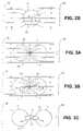
- FIGS. 3A , 3 B and 3 Care schematic illustrations of a dividing cell being subjected to an electric field, resulting in destruction of the cell ( FIG. 3C ), in accordance with an embodiment of the present invention
- FIG. 4is a schematic illustration of a dividing cell at one stage being subjected to an electric field
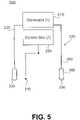
- FIG. 5is a schematic block diagram of an apparatus for applying an electric field according to one exemplary embodiment for selectively destroying cells
- FIG. 6is a simplified schematic diagram of an equivalent electric circuit of insulated electrodes of the apparatus of FIG. 5 ;
- FIG. 7is diagrammatic flow chart for computing an optimal electric field
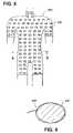
- FIG. 8is a front elevation view of an undershirt incorporating the present apparatus being worn over a human body
- FIG. 9is a cross-sectional taken along the line 9 — 9 ;
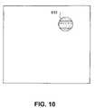
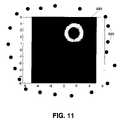
- FIG. 10is schematic view of a target area on which the electric field is to be focused
- FIG. 11is a photographic image of the optimal position of electrodes around the target area (tissue mass) of FIG. 10 ;
- FIG. 12is a schematic illustration of a geometric model for positioning electrodes around a spine of a human patient where the electrodes are arranged symmetrically;
- FIG. 13is an enlarged schematic illustration of one electrode of the arrangement of FIG. 12 ;
- FIG. 14is a photographic image of a resulting electric field generated when the electrodes are arranged symmetrically as illustrated in FIG. 12 ;
- FIG. 15is a schematic illustration representing the electric field of FIG. 14 by arrows;
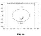
- FIG. 16is a schematic illustration of a geometric model for positioning electrodes around the spine in an asymmetric manner so that the electric field in the area of the spine is zero;
- FIG. 17is a photographic image of a resulting electric field generated when the electrodes are arranged asymmetrically as illustrated in FIG. 16 ;
- FIG. 18is a schematic illustration representing the electric field of FIG. 17 by arrows
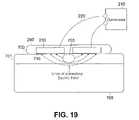
- FIG. 19is a cross-sectional illustration of a skin patch incorporating the apparatus of FIG. 5 and for placement on a skin surface for treating a tumor or the like;
- FIG. 20is a cross-sectional illustration of the insulated electrodes implanted within the body for treating a tumor or the like;
- FIG. 21is a cross-sectional illustration of the insulated electrodes implanted within the body for treating a tumor or the like;
- FIGS. 22A–22Dare cross-sectional illustrations of various constructions of the insulated electrodes of FIG. 5 ;
- FIG. 23is a front elevation view in partial cross-section of two insulated electrodes being arranged about a human torso for treatment of a tumor contained within the body, e.g., a tumor associated with lung cancer;
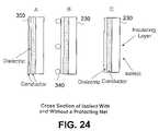
- FIGS. 24A–24Care cross-sectional illustrations of various insulated electrodes with and without protective members formed as a part of the construction thereof;
- FIG. 25is a schematic diagram of insulated electrodes that are arranged for focusing the electric field at a desired target while leaving other areas in low field density (i.e., protected areas);
- FIG. 26is a cross-sectional view of insulated electrodes incorporated into a hat according to a first embodiment for placement on a head for treating an intra-cranial tumor or the like;
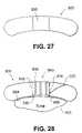
- FIG. 27is a partial section of a hat according to an exemplary embodiment having a recessed section for receiving one or more insulated electrodes;
- FIG. 28is a cross-sectional view of the hat of FIG. 27 placed on a head and illustrating a biasing mechanism for applying a force to the insulated electrode to ensure the insulated electrode remains in contact against the head;
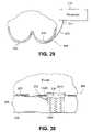
- FIG. 29is a cross-sectional top view of an article of clothing having the insulated electrodes incorporated therein for treating a tumor or the like;
- FIG. 30is a cross-sectional view of a section of the article of clothing of FIG. 29 illustrating a biasing mechanism for biasing the insulated electrode in a direction to ensure the insulated electrode is placed proximate to a skin surface where treatment is desired;
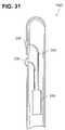
- FIG. 31is a cross-sectional view of a probe according to one embodiment for being disposed internally within the body for treating a tumor or the like;
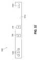
- FIG. 32is an elevation view of an unwrapped collar according to one exemplary embodiment for placement around a neck for treating a tumor or the like in the area where the collar is wrapped around the neck;
- FIG. 33is a side elevation view of the present apparatus being used to prevent restenosis of arteries after angioplasty.
- FIG. 34is an enlarged view of a stent used in the arrangement of FIG. 33 .
- FIGS. 1A–1Eschematically illustrate various stages of a cell division process.
- FIG. 1Ashows a cell 10 at its normal geometry, which may be generally spherical (as shown in the drawings), ellipsoidal, cylindrical, “pancake” like, or any other cell geometry, as is known in the art.
- FIGS. 1B–1Dshow cell 10 during different stages of its division process, which results in the formation of two new cells 18 and 20 , shown in FIG. 1E .
- the division process of cell 10is characterized by a slowly growing cleft 12 which gradually separates cell 10 into two units, namely, sub-cells 14 and 16 , which eventually evolve into new cells 18 and 20 ( FIG. 1E ).
- the division processis characterized by a transient period during which the structure of cell 10 is basically that of the two sub-cells 14 and 16 interconnected by a narrow “bridge” 22 containing cell material (cytoplasm surrounded by cell membrane).
- FIGS. 2A and 2Bschematically illustrate non-dividing cell 10 being subjected to an electric field produced by applying an alternating electric potential, at a relatively low frequency and at a relatively high frequency, respectively.
- Cell 10includes intracellular organelles, e.g., a nucleus 30 .
- Alternating electrical potentialis applied across electrodes 28 and 32 that may be attached externally to a patient at a predetermined region, e.g., in the vicinity of a tumor being treated.
- a conductive environmenthereinafter referred to as a “volume conductor” consisting mostly of electrolytic inter-cellular liquid.
- the specific distribution of the electric field lineswhich is substantially consistent with the direction of current flow in this case, depends on the geometry and the electric properties of the system components, e.g., the relative conductivities and dielectric constants of the system components, that may be frequency dependent. For low frequencies, e.g., frequencies considerably lower than 10 kHz, the conductance properties of the components dominate the current flow, and the field distribution is generally as depicted in FIG. 2A . At higher frequencies, e.g., at frequencies of between 10 kHz and 1 MHz, the dielectric properties of the components become more significant and eventually dominate the field distribution, resulting in field distribution lines as depicted generally in FIG. 2B .
- the dielectric properties of the various componentsare not significant in determining and computing the field distribution. Therefore, as a first approximation, with regard to the electric field distribution, the system can be reasonably represented by the relative impedances of its various components. Under this approximation, the intercellular (i.e., extracellular) fluid and the intracellular fluid have a relatively low impedance, while the cell membrane 11 has a relatively high impedance. Thus, under low frequency conditions, only a fraction of the electric field lines (or currents induced by the electric field) penetrate membrane 11 of cell 10 .
- the impedance of membrane 11 relative to the intercellular and intracellular fluidsdecreases and, thus, the fraction of currents penetrating the cells increases significantly. It should be noted that at very high frequencies, i.e., above 1 MHz, the membrane capacitance may short the membrane resistance and, therefore, the total membrane resistance may become negligible.
- the electric field linespenetrate cell 10 from a portion of membrane 11 closest to one of the electrodes generating the current, e.g., closest to positive electrode 28 (also referred to herein as “source”).
- the current flow pattern across cell 10is generally uniform because, under the above approximation, the field induced inside the cell is substantially homogenous.
- the currentsexit cell 10 through a portion of membrane 11 closest to the opposite electrode, e.g., negative electrode 32 (also referred to herein as “sink”).
- field lines and current flowmay depend on a number of factors, for example, on the frequency of the applied electric potential and on whether electrodes 28 and 32 are electrically insulated.
- insulated electrodesapplying a DC or low frequency alternating voltage, there is practically no current flow along the lines of the electric field.
- displacement currentsare induced in the tissue due to charging and discharging of the cell membranes (which act as capacitors to a certain extent), and such currents follow the lines of the electric field.
- Fields generated by non-insulated electrodesin contrast, always generate some form of current flow, specifically, DC or low frequency alternating fields generate conductive current flow along the field lines, and high frequency alternating fields generate both conduction and displacement currents along the field lines.
- the electric fields that are used in the present apparatusare alternating fields having frequencies that in the range from about 50 KHz to about 500 KHz, and preferably from about 100 KHz to about 300 KHz.
- these type of electric fieldsare also referred to hereinafter as “TC fields”, which is an abbreviation of “Tumor Curing electric fields”, since these electric fields fall into an intermediate category (between high and low frequency ranges) that have bio-effective field properties, while having no meaningful stimulatory and thermal effects.
- TC fieldsis an abbreviation of “Tumor Curing electric fields”
- These frequenciesare sufficiently low so that the system behavior is determined by the system's “Ohmic” (conductive) properties but sufficiently high enough not to have any stimulation effect on excitable tissues.
- Such a systemconsists of two types of elements, namely, the intercellular, or extracellular fluid, or medium and the individual cells.
- the intercellular fluidis mostly an electrolyte with a specific resistance of about 40–100 ohm*cm.
- the cellsare characterized by three elements, namely (1) a thin, highly electric resistive membrane that coats the cell; (2) internal cytoplasm that is mostly an electrolyte that contains numerous macromolecules and micro-organelles, including the nucleus; and (3) membranes, similar in their electric properties to the cell membranes, cover the micro-organelles.
- FIG. 2schematically depicts the resulting field distribution in the system.
- the lines of forcewhich also depict the lines of potential current flow across the cell volume mostly in parallel with the undistorted lines of force (the main direction of the electric field).
- the field inside the cellsis mostly homogeneous.
- the fraction of the field or current that penetrates the cellsis determined by the cell membrane impedance value relative to that of the extracellular fluid. Since the equivalent electric circuit of the cell membrane is that of a resistor and capacitor in parallel, the impedance is function of the frequency. The higher the frequency, the lower the impedance, the larger the fraction of penetrating current and the smaller the field distortion.
- FIGS. 3A–3Cschematically illustrate the electric current flow pattern in cell 10 during its division process, under the influence of high frequency alternating electric field in accordance with an embodiment of the invention.
- the field lines or induced currentspenetrate cell 10 through a part of the membrane of sub-cell 16 closer to electrode 28 . However, they do not exit through the cytoplasm bridge 22 that connects sub-cell 16 with the newly formed yet still attached sub-cell 14 , or through a part of the membrane in the vicinity of bridge 22 . Instead, the electric field or current flow lines—that are relatively widely separated in sub-cell 16 —converge as they approach bridge 22 (also referred to as “neck” 22 ) and, thus, the current/field line density within neck 22 is increased dramatically.
- a “mirror image” processtakes place in sub-cell 14 , whereby the converging field lines in bridge 22 diverge as they approach the exit region of sub-cell 14 .
- the direction of movement of polarized objectsis towards the higher density electric filed lines, i.e., towards the cytoplasm bridge 22 between sub-cells 14 and 16 .
- all intracellular organellesfor example, nuclei 24 and 26 of sub-cells 14 and 16 , respectively, are polarizable and, thus, such intracellular organelles will be electrically forced in the direction of bridge 22 . Since the movement is always from the lower density currents to the higher density currents, regardless of the field polarity, the forces applied by the alternating electric field to organelles such as nuclei 24 and 26 are always in the direction of bridge 22 .
- the movement of organelles 24 and 26 towards bridge 22disrupts the structure of the dividing cell and, eventually, the pressure of the converging organelles on bridge membrane 22 results in breakage of cell membrane 11 at the vicinity of bridge 22 , as shown schematically in FIG. 3C .
- the ability to break membrane 11 at bridge 22 and to otherwise disrupt the cell structure and organizationmay be enhanced by applying a pulsating AC electric field, rather than a steady AC field.
- a pulsating fieldWhen a pulsating field is applied, the forces acting on organelles 24 and 26 may have a “hammering” effect, whereby pulsed forces beat on the intracellular organelles at a desired rhythm, e.g., a pre-selected number of times per second.
- Such “hammering”is expected to enhance the movement of intracellular organelles towards neck 22 from both sub cells 14 and 16 ), thereby increasing the probability of breaking cell membrane 11 in the vicinity of neck 22 .
- FIG. 4a dividing cell 10 is illustrated, at an earlier stage as compared to FIGS. 3A and 3B , under the influence of external TC fields (e.g., alternating fields in the frequency range of about 100 KHz to about 300 KHz), generally indicated as lines 100 , with a corresponding spindle mechanism generally indicated at 120 .
- the lines 120are microtubules that are known to have a very strong dipole moment. This strong polarization makes the tubules susceptible to electric fields.
- the present apparatussince the present apparatus, as described in greater detail hereinafter, utilizes insulated electrodes, the above-mentioned negative effects obtained when conductive electrodes are used, i.e., ion concentration changes in the cells and the formation of harmful agents by electrolysis, do not occur when the present apparatus is used. This is because, in general, no actual transfer of charges takes place between the electrodes and the medium and there is no charge flow in the medium where the currents are capacitive, i.e., are expressed only as rotation of charges, etc.
- FIG. 5is a simple schematic diagram of the electronic apparatus 200 illustrating the major components thereof.
- the electronic apparatus 200generates the desired electric field signals (TC signals) in the shape of waveforms or trains of pulses.
- the apparatus 200includes a generator 210 and a set of pairs of conductive leads 220 that are attached at one end thereof to the generator 210 .
- the opposite ends of the leads 220are connected to the insulated conductors 230 that are activated by the electric signals (e.g., waveforms).
- the insulated conductors 230are also referred to hereinafter as “isolects” 230 .
- the apparatus 200includes a temperature sensor 240 or sensors and a control box 250 which are added to control the amplitude of the electric field generated so not to generate excessive heating in the area that is treated.
- the generator 210generates multiple alternating voltage waveforms at frequencies in the range from about 50 KHz to about 500 KHz (preferably from about 100 KHz to about 300 KHz)(i.e., the TC fields) as instructed by a controller 300 .
- the controller 300is a programmable unit, such as a personal computer or the like, that permits the user to input certain parameters and the controller 300 will then make the necessary computations.
- the controller 300also distributes to each electrode 230 the designated potential wave.
- the required voltagesare such the electric field intensity in the tissue to be treated is in the range of about 0.1V/cm, according to one exemplary embodiment, to about 10V/cm while in the other areas it is significantly lower.
- control box 250When the control box 250 is included, it controls the outputs of the generator 210 so that they will remain constant at the values preset by the user or the control box 250 .
- the controller 300issues a warning or the like when the temperature (sensed by temperature sensor 240 ) exceeds a preset limit.
- the details of the construction of the isolects 230is based on their electric behavior that can be understood from their simplified electric circuit when in contact with tissue as generally illustrated in FIG. 6 .
- the potential drop or the electric field distribution between the different componentsis determined by their relative electric impedance, i.e., the fraction of the field on each component is given by the value of its impedance divided by the total circuit impedance.
- the potential drop on element ⁇ V AA/(A+B+C+D+E).
- the impedance of the capacitance of the capacitorsis dominant and determines the field distribution. Therefore, in order to increase the effective voltage drop across the tissues (field intensity), the impedance of the capacitors is to be decreased (i.e., increase their capacitance). This can be achieved by increasing the effective area of the “plates” of the capacitor, decrease the thickness of the dielectric or use a dielectric with high dielectric constant.
- the isolects 230are configured differently depending upon the application in which the isolects 230 are to be used. There are two principle modes for applying the present electric fields (TC fields). First, the TC fields can be applied by external isolects and second, the TC fields can be applied by internal isolects.
- the insulationcan be replaced by very high dielectric constant insulating materials, such as titanium dioxide (e.g., rutil), the dielectric constant can reach values of about 200.
- dielectric constant insulating materialssuch as titanium dioxide (e.g., rutil)
- the dielectric constantcan reach values of about 200.
- lithium nibate(LiNbO 3 ), which is a ferroelectric crystal and has a number of applications in optical, pyroelectric and piezoelectric devices
- yittrium iron garnet(YIG) is a ferrimagnetic crystal and magneto-optical devices, e.g., optical isolator can be realized from this material
- barium titanate(BaTiO 3 ) is a ferromagnetic crystal with a large electro-optic effect
- potassium tantalate(KTaO 3 ) which is a dielectric crystal (ferroelectric at low temperature) and has very low microwave loss and tunability of dielectric constant at low temperature
- lithium tantalate(LiTaO 3 ) which is a ferroelectric crystal with similar properties as lithium niobate and has utility in electro-optical, pyroelectric and piezoelectric devices.
- the aforementioned exemplary materialscan be used in combination with the present device where it is desired to use a material having
- the isolects 230can be shaped so as to conform with the body structure and/or (2) an intervening filler 270 (as illustrated in FIG. 22C ), such as a gel, that has high conductance and a high effective dielectric constant, can be added to the structure.
- the shapingcan be pre-structured (see FIG.
- the gel 22Acan be made sufficiently flexible so that shaping of the isolects 230 is readily achievable.
- the gelcan be made of hydrogels, gelatins, agar, etc., and can have salts dissolved in it to increase its conductivity.
- the exact thickness of the gelis not important so long as it is of sufficient thickness that the gel layer does not dry out during the treatment. In one exemplary embodiment, the thickness of the gel is about 0.5 mm to about 2 mm.
- the isolects insulating materialshould have minimal dielectric losses at the frequency ranges to be used during the treatment process. This factor can be taken into consideration when choosing the particular frequencies for the treatment.
- the direct heating of the tissueswill most likely be dominated by the heating due to current flow (given by the I*R product).
- dielectric lossescan also contribute and in addition, the isolect (insulated electrode) 230 and its surroundings should be made of materials that facilitate heat losses and its general structure should also facilitate head losses, i.e., minimal structures that block heat dissipation to the surroundings (air) as well as high heat conductivity.
- a coupling agentsuch as a conductive gel
- the coupling agentis disposed on the insulated electrode 230 and preferably, a uniform layer of the agent is provided along the surface of the electrode 230 .
- the coupling agentneeds to be replaced and/or replenished. In other words, after a predetermined time period or after a number of uses, the patient removes the units 540 so that the coupling agent can be applied again to the electrode 230 .
- the leads 220are standard isolated conductors with a flexible metal shield, preferably grounded so that it prevents the spread of the electric field generated by the leads 220 .
- the isolects 230have specific shapes and positioning so as to generate an electric field of the desired configuration, direction and intensity at the target volume and only there so as to focus the treatment. The generation of electric field distribution of the desired characteristics is achieved by placement of numerous isolects on the body surface, and when necessary also inside the body.
- the number of electrodes 230can typically be about 20–100, placed about 4–12 cm apart.
- the electrodes 230can be positioned individually on the skin, etc., (as by an adhesive), or be part of an article of clothing, such as elastic undershirt, as illustrated in FIGS.
- Each isolect 230(electrode) is connected to the controller 300 and is provided with a voltage signal the amplitude and shape of which was calculated specifically for the particular electrode.
- the calculation for the voltage signalcan be made for groups of isolects as well instead of for individual isolects.
- a method for optimizing the selective destruction of dividing cellsincludes the general steps of calculating the spatial and temporal distribution of electric fields for optimal treatment of a specific patient that has a tumor of specific characteristics. This calculation takes into consideration the location and the specific characteristics of the tumor.
- FIG. 7thus gives a general overview of the present optimization process.
- the userinputs different types of information that is used to compute the optimal electric field. For example, at step 400 , the user inputs characteristics of the tissue cells in the area to be treated; at step 410 , the user inputs characteristics of the tumor cells to be treated; and at step 420 , the user inputs the anatomy of the area to be treated, including the tumor and its relevant surroundings.
- this inputted informationis used to compute the necessary field intensity in the tumor.
- the relative sensitivities of the non-tumor tissues to the electric fieldsis computed in step 440 .
- the maximal allowed field intensity at the various areasis determined and then based on the information inputted in steps 400 through 450 , an optimal field map is computed at step 460 .
- the selected isolects(those present in the optimal field map) are computed as well as their position and waveform and the voltage that is to be delivered to each isolect.
- the number of isolectsis preferably reduced in step 480 to produce a modified field map and then the deviation of the modified map from the optimum is calculated. The calculated deviation is then compared to an inputted threshold value and if the calculated deviation is below the inputted threshold, the process of reducing the number of isolects is continued until the inputted threshold is obtained.
- a signalis delivered to the controller to activate the reduced number of isolects.
- a signalis generated and delivered to the function generating system (e.g., the generator that produces the waveforms mentioned in step 470 , such as an analog wave generator or a digital one, e.g., a waveform generated by a PC and outputted through a digital to analog converter) or the system is otherwise instructed to provide the selected waveform and voltage to the isolects.
- the field that results from activation of the isolectsis monitored at step 510 and any errors are corrected. If any errors or abnormalities are detected, the field is modified as necessary according to the treatment protocol at step 520 .
- the various algorithms that are used for the necessary computationsare described hereinafter.
- the signal that is delivered to each electrodeis a voltage signal that has been specifically created for the specific electrode or for a specific group of electrodes, the calculation of this voltage signal is an important aspect of the present invention.
- the voltages for the isolectsare calculated as follows. Following the anatomical definition of the areas to be treated, taking into consideration the specific sensitivity of the different tissues to the TC fields and the target area, the desired field distribution map is constructed, as described in the flow chart of FIG. 7 .
- the processorwhich was fed the coordinates of all available isolects, now computes the vector sum of the fields generated by each isolect at each point in time. The computation can be made significantly faster in cases where an analytical expression for the electric field originating from arbitrary placed electrodes is available. Such a computation can be performed, for example, for the simple case; an isolect placed on a muscle, or similar tissue, for which an analytical expression for the electric field is:
- R 1is the radius of the metallic part of the isolect
- R 2is the isolect radius including coating ⁇ coat and ⁇ muscle are the dielectric constants of the isolect coating and muscle, respectively and r is the distance between the electrodes to the point where one wants to calculate the field.
- the fields generated in more complex systemsare usually computed by finite element methods, as described below.
- TC fieldthe calculated electric field
- TC fieldthe desired electric field
- the robust numeric optimization methodknown as the Nelder-Mead simplex method, as described in Neider and Mead, Computer Journal Vol. 7, p. 308 (1965); Lagarias, J. C., J. A. Reeds, M. H. Wright and P. E. Wright “Convergence Properties of the Neider-Mead Simplex Method in Low Dimensions”, SIAM Journal of Optimization, Vol. 9, Number 1, pp. 112–147, 1986, all of which are hereby incorporated by reference in their entirety.
- the calculations of the optimization methodinclude the method “Sequential Quadratic Programming”, and this method is intended for checking that the first one went fine.
- the referencesinclude Fletcher, R.
- the undershirt 600can be of an oversized type in that, as illustrated, the undershirt 600 extends below the waist of the patient and in fact, it protrudes around a portion of the user's upper legs (thighs); however, it will be appreciated that the undershirt 600 can be of a more conventional type that lies above the waist.
- the undershirt 600has a predetermined number of electrodes 230 (e.g., 20–100 in number) that are arranged either in an orderly manner as shown (rows and columns) or they can be arranged in a irregular pattern depending upon where the optimal positioning of the electrodes 230 is determined to be.
- the electrodes 230are held in place by the undershirt construction, e.g., by adhesives or by stitching, etc. As shown in FIG. 9 , the electrodes 230 completely extend radially around the body of the patient.
- this type of procedurewas carried out with the aim to effectively focus the field at the selected area, which in this Figure is denoted by the circle 610 .
- random initialization of the electrode voltage and positionswere used.
- the calculated optimal position of the electrodesdepicted by circles 620 , is illustrated around the tissue mass 630 where the electric field (TC field) intensity is minimal, as denoted by 640 , while the intensity of the electric field increases in the vicinity of the target (tissue mass) 630 .
- FIGS. 12–18In yet another example of the procedure of calculating the isolect placement that would give high field intensity at a number of skin locations, for treatment of malignant melanoma's while having minimal field at the spine is illustrated and described with reference to FIGS. 12–18 .
- FIGS. 12–18In this example, one will appreciate how the anatomy, the isolect structure and the tissue electric characteristics are incorporated into the calculations.
- One of the advantages of using an electric field to repress the prosperity of cellsis that areas inside a human being can be left outside of the electric field influence.
- a modelis constructed for a human having four electrodes around the mid body portion and the electrodes are specifically arranged so that the electric field around the human's spine is zero.
- FIG. 12shows the location of the spine 650 relative to four electrodes 660 that are spaced therearound.
- a skin boundary or layer of the patientis generally shown at 670 with muscle 680 being shown as occupying the area within the skin boundary 670 and around the spine 650 .
- FIG. 13is also a geometric model illustrating an enlargement of the area around one electrode 670 of FIG. 12 showing the interaction between the electrode 670 and the skin layer 670 .
- the axis units in FIG. 13are in millimeters and in this exemplary embodiment, the electrode 660 includes a coating 662 that is formed of PVC or potassium tantalate.
- the electrode 660has a diameter of about 10 mm and the coating 662 that is disposed around an outer surface 661 thereof has a thickness of about 0.1 mm.
- the skin layer 670has a thickness of about 1 mm. Table 1 sets forth the parameters for the materials that are used in the calculations that are used with the geometric models of FIGS. 12 and 13 .
- the voltage between the electrodes 660was 1V and the frequency of the sine voltage was 100 KHz.
- FIG. 14is photographic image of the electrodes 660 around the spine 650 illustrating the electric field representation in the symmetric formation of the electrodes.
- FIG. 15is another representation of the electric field; however, this representation of the electric field is by arrows. As will be appreciated, only the electric field inside the body is shown. As can be seen from both FIGS. 14 and 15 , the electric field is zero in the middle of the body and is very high in the area of the spine 650 . This is unwanted since the presence of the electric field near the spine 650 can be potentially harmful.
- FIG. 14is photographic image of the electrodes 660 around the spine 650 illustrating the electric field representation in the symmetric formation of the electrodes.
- FIG. 15is another representation of the electric field; however, this representation of the electric field is by arrows. As will be appreciated, only the electric field inside the body is shown. As can be seen from both FIGS. 14 and 15 , the electric field is zero in the middle of the body and is very high in the area of the spine 650 . This is unwanted since
- FIG. 16is a schematic illustration of the arrangement of the electrodes 660 that causes a zero electric field in the area of the spine 650 .
- FIG. 17is a photographic image of the electric field in an asymmetric formation of the electrodes and
- FIG. 18is another representation of the electric field, similar to FIG. 15 , in which the electric field is represented by arrows and only the electric field inside the body is drawn.
- the asymmetric arrangement of the electrodescauses a zero electric field in the area of the spine 650 , while the field outside the spine 650 is not zero.
- a proper arrangement of the electrodescan shape the electric field so that it becomes zero at areas we choose, such as the spine area 650 , in this example.
- the procedurecan entail using a CT image to position the internal organs, calculate on-line the electric field using the present methodology and automatically position the electrodes on the patient's body so that an area that we do not want to harm will not suffer from the presence of an electric field.
- the specifications of the apparatus 200 as a whole and its individual componentsare largely influenced by the fact that at the frequency of the present TC fields (50 KHz–500 KHz), living systems behave according to their “Ohmic”, rather than their dielectric properties.
- the only elements in the apparatus 200 that behave differentlyare the insulators of the isolects 230 (see FIGS. 19–21 ).
- the isolects 200consist of a conductor in contact with a dielectric that is in contact with the conductive tissue thus forming a capacitor.
- FIG. 19illustrates an exemplary embodiment where the isolects 230 are incorporated in a skin patch 700 .
- the skin patch 700can be a self-adhesive flexible patch with one or more pairs of isolects 230 .
- the patch 700includes internal insulation 710 (formed of a dielectric material) and the external insulation 260 and is applied to skin surface 701 that contains a tumor 703 either on the skin surface 701 or slightly below the skin surface 701 . Tissue is generally indicated at 705 .
- the internal insulation 710must have a relatively high capacity. This can be achieved by a large surface area; however, this may not be desired as it will result in the spread of the field over a large area (e.g., an area larger than required to treat the tumor).
- the internal insulation 710can be made very thin and/or the internal insulation 710 can be of a high dielectric constant. As the skin resistance between the electrodes (labeled as A and E in FIG. 6 ) is normally significantly higher than that of the tissue (labeled as C in FIG. 6 ) underneath it (1–10 K ⁇ vs. 0.1–1 K ⁇ ), most of the potential drop beyond the isolects occurs there.
- the characteristics of the internal insulation 710should be such that they have impedance preferably under 100 K ⁇ at the frequencies of the present TC fields (e.g., 50 KHz to 500 KHz).
- the impedancepreferably under 100 K ⁇ at the frequencies of the present TC fields (e.g., 50 KHz to 500 KHz).
- the capacityshould be on the order of 10 ⁇ 10 F, which means that using standard insulations with a dielectric constant of 2–3, the thickness of the insulating layer 710 should be about 50–100 microns.
- An internal field 10 times strongerwould be obtained with insulators with a dielectric constant of about 20–50.
- FIGS. 20 and 21illustrate a second type of treatment using the isolects 230 , namely electric field generation by internal isolects 230 .
- a body to which the isolects 230 are implantedis generally indicated at 711 and includes a skin surface 713 and a tumor 715 .
- the isolects 230can have the shape of plates, wires or other shapes that can be inserted subcutaneously or a deeper location within the body 711 so as to generate an appropriate field at the target area (tumor 715 ).
- FIG. 22illustrates the various constructions of the isolects 230 , including the use of internal insulation 710 , a filler or gel 270 and external insulation 260 .
- the mode of isolects applicationis not restricted to the above descriptions.
- the distance between each member of the pair of isolects 230can be large.
- the pairscan even by positioned opposite sides of a torso 720 , as illustrated in FIG. 23 .
- the arrangement of the isolects 230 in FIG. 23is particularly useful for treating a tumor 730 associated with lung cancer or gastrointestinal tumors.
- the electric fields (TC fields)spread in a wide fraction of the body.
- the dielectric coating of eachshould be very thin, for example from between 1–50 microns. Since the coating is so thin, the isolects 230 can easily be damaged mechanically. This problem can be overcome by adding a protective feature to the isolect's structure so as to provide desired protection from such damage.
- the isolect 230can be coated, for example, with a relatively loose net 340 that prevents access to the surface but has only a minor effect on the effective surface area of the isolect 230 (i.e., the capacity of the isolects 230 (cross section presented in FIG. 24B ). The loose net 340 does not effect the capacity and ensures good contact with the skin, etc.
- the loose net 340can be formed of a number of different materials; however, in one exemplary embodiment, the net 340 is formed of nylon, polyester, cotton, etc.
- a very thin conductive coating 350can be applied to the dielectric portion (insulating layer) of the isolect 230 .
- One exemplary conductive coatingis formed of a metal and more particularly of gold. The thickness of the coating 350 depends upon the particular application and also on the type of material used to form the coating 350 ; however, when gold is used, the coating has a thickness from about 0.1 micron to about 0.1 mm.
- the isolects insulating materialshould have minimal dielectric losses at the frequency ranges to be used during the treatment process. This factor can be taken into consideration when choosing the particular frequencies for the treatment. The direct heating of the tissues will most likely be dominated by the heating due to current flow (given by the I*R product).
- the isolect (insulated electrode) 230 and its surroundingsshould be made of materials that facilitate heat losses and its general structure should also facilitate head losses, i.e., minimal structures that block heat dissipation to the surroundings (air) as well as high heat conductivity.
- the effectiveness of the treatmentcan be enhanced by an arrangement of isolects 230 that focuses the field at the desired target while leaving other sensitive areas in low field density (i.e., protected areas).
- the proper placement of the isolects 230 over the bodycan be maintained using any number of different techniques, including using a suitable piece of clothing that keeps the isolects at the appropriate positions.
- FIG. 25illustrates such an arrangement in which an area labeled as “P” represents a protected area. The lines of field force do not penetrate this protected area and the field there is much smaller than near the isolects 230 where target areas can be located and treated well. In contrast, the field intensity near the four poles is very high.
- the present apparatuscan further include a device for rotating the TC field relative to the living tissue.
- the alternating electric potentialapplies to the tissue being treated is rotated relative to the tissue using conventional devices, such as a mechanical device that upon activation, rotates various components of the present system.
- the TC fieldsare applied to different pairs of the insulated electrodes 230 in a consecutive manner.
- the generator 210 and the control system thereofcan be arranged so that signals are sent at periodic intervals to select pairs of insulated electrodes 230 , thereby causing the generation of the TC fields of different directions by these insulated electrodes 230 .
- the signalsare sent at select times from the generator to the insulated electrodes 230 , the TC fields of changing directions are generated consecutively by different insulated electrodes 230 .
- This arrangementhas a number of advantages and is provided in view of the fact that the TC fields have maximal effect when they are parallel to the axis of cell division. Since the orientation of cell division is in most cases random, only a fraction of the dividing cells are affected by any given field. Thus, using fields of two or more orientations increases the effectiveness since it increases the chances that more dividing cells are affected by a given TC field.
- the article of clothing 800is in the form of a hat or cap or other type of clothing designed for placement on a head of a person.
- a head 802is shown with the hat 800 being placed thereon and against a skin surface 804 of the head 802 .
- An intra-cranial tumor or the like 810is shown as being formed within the head 802 underneath the skin surface 804 thereof.
- the hat 800is therefore intended for placement on the head 802 of a person who has a tumor 810 or the like.
- the hat 800includes a predetermined number of insulated electrodes 230 that are preferably positioned so as to produce the optimal TC fields at the location of the tumor 810 .
- the lines of force of the TC fieldare generally indicated at 820 .
- the tumor 810is positioned within these lines of force 820 .
- the insulated electrodes 230are positioned within the hat 800 such that a portion or surface thereof is free to contact the skin surface 804 of the head 802 .
- the insulated electrodes 230are placed in contact with the skin surface 804 of the head 802 in positions that are selected so that the TC fields generated thereby are focused at the tumor 810 while leaving surrounding areas in low density.
- hair on the head 802is shaved in selected areas to permit better contact between the insulated electrodes 230 and the skin surface 804 ; however, this is not critical.
- the hat 800preferably includes a mechanism 830 that applies or force to the insulated electrodes 230 so that they are pressed against the skin surface 802 .
- the mechanism 830can be of a biasing type that applies a biasing force to the insulated electrodes 230 to cause the insulated electrodes 230 to be directed outwardly away from the hat 800 .
- the mechanism 830can slightly recoil to provide a comfortable fit between the insulated electrodes 230 and the head 802 .
- the mechanism 830is a spring based device that is disposed within the hat 800 and has one section that is coupled to and applies a force against the insulated electrodes 230 , as described below with reference to FIGS. 27 and 28 .
- the insulated electrodes 230are coupled to the generator 210 by means of conductors 220 .
- the generator 210can be either disposed within the hat 800 itself so as to provide a compact, self-sufficient, independent system or the generator 210 can be disposed external to the hat 800 with the conductors 220 exiting the hat 800 through openings or the like and then running to the generator 210 .
- the generator 210can be located in any number of different locations, some of which are in close proximity to the hat 800 itself, while others can be further away from the hat 800 .
- the generator 210can be disposed within a carrying bag or the like (e.g., a bag that extends around the patient's waist) which is worn by the patient or it can be strapped to an extremity or around the torso of the patient.
- the generator 210can also be disposed in a protective case that is secured to or carried by another article of clothing that is worn by the patient.
- the protective casecan be inserted into a pocket of a sweater, etc.
- FIG. 26illustrates an embodiment where the generator 210 is incorporated directly into the hat 800 .
- a number of insulated electrodes 230 along with the mechanism 830are preferably formed as an independent unit, generally indicated at 840 , that can be inserted into the hat 800 and electrically connected to the generator (not shown) via the conductors (not shown).
- the patientcan easily insert and/or remove the units 840 from the hat 800 when they may need cleaning, servicing and/or replacement.
- the hat 800is constructed to include select areas 850 that are formed in the hat 800 to receive and hold the units 840 .
- each area 850is in the form of an opening (pore) that is formed within the hat 800 .
- the unit 840has a body 842 and includes the mechanism 830 and one or more insulated electrodes 230 .
- the mechanism 830is arranged within the unit 840 so that a portion thereof (e.g., one end thereof) is in contact with a face of each insulated electrode 230 such that the mechanism 830 applies a biasing force against the face of the insulated electrode 230 .
- the hat 800can include pivotable clip members that pivot between an open position in which the opening 850 is free and a closed position in which the pivotable clip members engage portions (e.g., peripheral edges) of the insulated electrodes to retain and hold the insulated electrodes 230 in place. To remove the insulated electrodes 230 , the pivotable clip members are moved to the open position. In the embodiment illustrated in FIG.
- the insulated electrodes 230are retained within the openings 850 by an adhesive element 860 which in one embodiment is a two sided self-adhesive rim member that extends around the periphery of the insulated electrode 230 .
- an adhesive element 860which in one embodiment is a two sided self-adhesive rim member that extends around the periphery of the insulated electrode 230 .
- a protective cover of one side of the adhesive rim 860is removed and it is applied around the periphery of the exposed face of the insulated electrode 230 , thereby securely attaching the adhesive rim 860 to the hat 800 and then the other side of the adhesive rim 860 is removed for application to the skin surface 804 in desired locations for positioning and securing the insulated electrode 230 to the head 802 with the tumor being positioned relative thereto for optimization of the TC fields.
- one side of the adhesive rim 860is in contact with and secured to the skin surface 840 , this is why it is desirable for the head
- the adhesive rim 860is designed to securely attach the unit 840 within the opening 850 in a manner that permits the unit 840 to be easily removed from the hat 800 when necessary and then replaced with another unit 840 or with the same unit 840 .
- the unit 840includes the biasing mechanism 830 for pressing the insulated electrode 230 against the skin surface 804 when the hat 800 is worn.
- the mechanism 830can be a spring, there are a number of other embodiments that can be used instead of a spring.
- the mechanism 830can be in the form of an elastic material, such as a foam rubber, a foam plastic, or a layer containing air bubbles, etc.
- the unit 840has an electric connector 870 that can be hooked up to a corresponding electric connector, such as a conductor 220 , that is disposed within the hat 800 .
- the conductor 220connects at one end to the unit 840 and at the other end is connected to the generator 210 .
- the generator 210can be incorporated directly into the hat 800 or the generator 210 can be positioned separately (remotely) on the patient or on a bedside support, etc.
- a coupling agentsuch as a conductive gel
- a coupling agentis preferably used to ensure that an effective conductive environment is provided between the insulated electrode 230 and the skin surface 804 .
- Suitable gel materialshave been disclosed hereinbefore in the discussion of earlier embodiments.
- the coupling agentis disposed on the insulated electrode 230 and preferably, a uniform layer of the agent is provided along the surface of the electrode 230 .
- One of the reasons that the units 840 need replacement at periodic timesis that the coupling agent needs to be replaced and/or replenished. In other words, after a predetermined time period or after a number of uses, the patient removes the units 840 so that the coupling agent can be applied again to the electrode 230 .
- FIGS. 29 and 30illustrate another article of clothing which has the insulated electrodes 230 incorporated as part thereof.
- a bra or the like 900is illustrated and includes a body that is formed of a traditional bra material, generally indicated at 905 , to provide shape, support and comfort to the wearer.
- the bra 900also includes a fabric support layer 910 on one side thereof.
- the support layer 910is preferably formed of a suitable fabric material that is constructed to provide necessary and desired support to the bra 900 .
- the bra 900includes one or more insulated electrodes 230 disposed within the bra material 905 .
- the one or more insulated electrodesare disposed along an inner surface of the bra 900 opposite the support 910 and are intended to be placed proximate to a tumor or the like that is located within one breast or in the immediately surrounding area.
- the insulated electrodes 230 in this embodimentare specifically constructed and configured for application to a breast or the immediate area.
- the insulated electrodes 230 used in this applicationdo not have a planar surface construction but rather have an arcuate shape that is complementary to the general curvature found in a typical breast.
- a lining 920is disposed across the insulated electrodes 230 so as to assist in retaining the insulated electrodes in their desired locations along the inner surface for placement against the breast itself.
- the lining 920can be formed of any number of thin materials that are comfortable to wear against one's skin and in one exemplary embodiment, the lining 920 is formed of a fabric material.
- the bra 900also preferably includes a biasing mechanism 1000 as in some of the earlier embodiments.
- the biasing mechanism 1000is disposed within the bra material 905 and extends from the support 910 to the insulated electrode 230 and applies a biasing force to the insulated electrode 230 so that the electrode 230 is pressed against the breast. This ensures that the insulated electrode 230 remains in contact with the skin surface as opposed to lifting away from the skin surface, thereby creating a gap that results in a less effective treatment since the gap diminishes the efficiency of the TC fields.
- the biasing mechanism 1000can be in the form of a spring arrangement or it can be an elastic material that applies the desired biasing force to the insulated electrodes 230 so as to press the insulated electrodes 230 into the breast.
- the biasing mechanism 1000applies a force against the insulated electrodes 230 and when the patient places the bra 900 on their body, the insulated electrodes 230 are placed against the breast which itself applies a force that counters the biasing force, thereby resulting in the insulated electrodes 230 being pressed against the patient's breast.
- the biasing mechanism 1000is in the form of springs that are disposed within the bra material 905 .
- a conductive gel 1010can be provided on the insulated electrode 230 between the electrode and the lining 920 .
- the conductive gel layer 1010is formed of materials that have been previously described herein for performing the functions described above.
- the compartmentcan be covered with a releasable strap that can open and close to permit the generator 210 to be inserted therein or removed therefrom.
- the strapcan be formed of the same material that is used to construct the bra 900 or it can be formed of some other type of material.
- the strapcan be releasably attached to the surrounding bra body by fastening means, such as a hook and loop material, thereby permitting the patient to easily open the compartment by separating the hook and loop elements to gain access to the compartment for either inserting or removing the generator 210 .
- the generator 210also has a connector 211 for electrical connection to the conductor 220 and this permits the generator 210 to be electrically connected to the insulated electrodes 230 .
- the insulated electrodes 230are arranged in the bra 900 to focus the electric field (TC fields) on the desired target (e.g., a tumor).
- TC fieldselectric field
- the location of the insulated electrodes 230 within the bra 900will vary depending upon the location of the tumor.
- the physicianwill then devise an arrangement of insulated electrodes 230 and the bra 900 is constructed in view of this arrangement so as to optimize the effects of the TC fields on the target area (tumor).
- the number and position of the insulated electrodes 230will therefore depend upon the precise location of the tumor or other target area that is being treated.
- the exact size and shape of the insulated electrodes 230can likewise vary. For example, if the insulated electrodes 230 are placed on the bottom section of the bra 900 as opposed to a more central location, the insulated electrodes 230 will have different shapes since the shape of the breast (as well as the bra) differs in these areas.
- FIG. 31illustrates yet another embodiment in which the insulated electrodes 230 are in the form of internal electrodes that are incorporated into in the form of a probe or catheter 1100 that is configured to enter the body through a natural pathway, such as the urethra, vagina, etc.
- the insulated electrodes 230are disposed on an outer surface of the probe 1100 and along a length thereof.
- the conductors 220are electrically connected to the electrodes 230 and run within the body of the probe 1100 to the generator 210 which can be disposed within the probe body or the generator 210 can be disposed independent of the probe 1100 in a remote location, such as on the patient or at some other location close to the patient.
- the probe 1100can be configured to penetrate the skin surface or other tissue to reach an internal target that lies within the body.
- the probe 1100can penetrate the skin surface and then be positioned adjacent to or proximate to a tumor that is located within the body.
- the probe 1100is inserted through the natural pathway and then is positioned in a desired location so that the insulated electrodes 230 are disposed near the target area (i.e., the tumor).
- the generator 210is then activated to cause the insulated electrodes 230 to generate the TC fields which are applied to the tumor for a predetermined length of time.
- the illustrated probe 1100is merely exemplary in nature and that the probe 1100 can have other shapes and configurations so long as they can perform the intended function.
- the conductors (e.g., wires) leading from the insulated electrodes 230 to the generator 210are twisted or shielded so as not to generate a field along the shaft.
- the probescan contain only one insulated electrode while the other can be positioned on the body surface.
- This external electrodeshould be larger or consist of numerous electrodes so as to result in low lines of force-current density so as not to affect the untreated areas.
- the placing of electrodesshould be designed to minimize the field at potentially sensitive areas.
- the collar body 1210can be formed of any number of materials that are traditionally used to form collars 1200 that are disposed around a person's neck.
- the collar 1200preferably includes a means 1220 for adjusting the collar 1200 relative to the neck.
- complementary fastenerscan be disposed on ends of the collar 1200 to permit adjustment of the collar diameter. It will be appreciated that one can extend this exemplary structure to accommodate any tubular part of the body, e.g., a limb, etc.
- FIGS. 33 and 34illustrate yet another embodiment of the present device.
- a pair of electrodes 230are arranged about a torso 1300 .
- the electrodes 230are operated in the same manner as was previously described and in this embodiment, the electrodes 230 are arranged so that the electric field passes through the heart and its surrounding area.
- the electrodes 230are arranged about the torso 1300 so that the TC fields, indicated by field lines 1310 , passes through the heart region 1320 .
- a coronary artery 1330is illustrated within the heart region 1320 and within the TC fields.
- One or more stents 1340are disposed within the coronary artery 1330 as part of the surgical procedure.
- One of the results of the angioplasty and mainly due to the presence of the stents 1340is a proliferation of a mass of cells 1350 that is located along the artery wall. Since the stent 1340 acts as a conductor, the area around the stent 1340 is an area of high density electric field due to the presence of the stent 1340 .
- the stent 1340does not necessarily have to be a bare metal conductor and the present method of treatment can be used without stents 1340 so long as the mass of proliferating cells 1350 is disposed within the area of the high density electric field.
- an article of clothing in the form of a sock-like structure or wrapcan be provided and is configured to be worn around the testicle area of the patient in such a manner that the insulated electrodes thereof are positioned relative to the tumor such that the TC fields are directed at the target tissue.
- the precise nature or form of the article of clothingcan vary greatly since the device components can be incorporated into most types of articles of clothing and therefore, can be used to treat any number of different areas of the patient's body where a condition may be present.
- tumorrefers to a malignant tissue comprising transformed cells that grow uncontrollably.
- Tumorsinclude leukemias, lymphomas, myelomas, plasmacytomas, and the like; and solid tumors.
- solid tumorsinclude sarcomas and carcinomas such as, but not limited to: fibrosarcoma, myxosarcoma, liposarcoma, chondrosarcoma, osteogenic sarcoma, chordoma, angiosarcoma, endotheliosarcoma, lymphangiosarcoma, lymphangioendotheliosarcoma, synovioma, mesothelioma, Ewing's tumor, leiomyosarcoma, rhabdomyosarcoma, colon carcinoma, pancreatic cancer, breast cancer, ovarian cancer, prostate cancer, squamous cell carcinoma, basal cell carcinoma, adenocarcinom
- the inventionis particularly advantageous for treating brain tumors, which are difficult to treat with surgery and radiation, and often inaccessible to chemotherapy or gene therapies.
- the present inventionis suitable for use in treating skin and breast tumors because of the ease of localized treatment provided by the present invention.
- the present inventioncan control uncontrolled growth associated with non-malignant or pre-malignant conditions, and other disorders involving inappropriate cell or tissue growth by application of an electric field in accordance with the invention to the tissue undergoing inappropriate growth.
- the inventionis useful for the treatment of arteriovenous (AV) malformations, particularly in intracranial sites.
- AVarteriovenous
- the inventionmay also be used to treat psoriasis, a dermatologic condition that is characterized by inflammation and vascular proliferation; and benign prostatic hypertrophy, a condition associated with inflammation and possibly vascular proliferation. Treatment of other hyperproliferative disorders is also contemplated.
- undesirable fibroblast and endothelial cell proliferation associated with wound healing, leading to scar and keloid formation after surgery or injury, and restenosis after angioplasty or placement of coronary stentscan be inhibited by application of an electric field in accordance with the present invention.
- the non-invasive nature of this inventionmakes it particularly desirable for these types of conditions, particularly to prevent development of internal scars and adhesions, or to inhibit restenosis of coronary, carotid, and other important arteries.
- the present inventionprovides an effective, simple method of selectively destroying dividing cells, e.g., tumor cells and parasitic organisms, while non-dividing cells or organisms are left affected by application of the method on living tissue containing both types of cells or organisms.
- the present inventiondoes not damage the normal cells or organisms.
- the present inventiondoes not discriminate based upon cell type (e.g., cells having differing sizes) and therefore may be used to treat any number of types of sizes having a wide spectrum of characteristics, including varying dimensions.
Landscapes
- Health & Medical Sciences (AREA)
- Life Sciences & Earth Sciences (AREA)
- Public Health (AREA)
- Nuclear Medicine, Radiotherapy & Molecular Imaging (AREA)
- Radiology & Medical Imaging (AREA)
- Biomedical Technology (AREA)
- Animal Behavior & Ethology (AREA)
- General Health & Medical Sciences (AREA)
- Engineering & Computer Science (AREA)
- Veterinary Medicine (AREA)
- Pain & Pain Management (AREA)
- Orthopedic Medicine & Surgery (AREA)
- Cell Biology (AREA)
- Neurology (AREA)
- Neurosurgery (AREA)
- Biophysics (AREA)
- Heart & Thoracic Surgery (AREA)
- Apparatus Associated With Microorganisms And Enzymes (AREA)
- Micro-Organisms Or Cultivation Processes Thereof (AREA)
Abstract
Description
| TABLE 1 |
| Material Data |
| Dielectric | Dielectric | |||
| medium | Constant | Conductivity (S/m) | ||
| 1 | 0 | |||
| PVC Coating | 2.6 | 0 | ||
| Muscle | 8089 | 0.36 | ||
| Skin | 1119 | 0.00045 | ||
| Spine | 227 | 0.0208 | ||
Claims (19)
Priority Applications (15)
| Application Number | Priority Date | Filing Date | Title |
|---|---|---|---|
| US10/402,327US7146210B2 (en) | 2000-02-17 | 2003-03-28 | Apparatus and method for optimizing tumor treatment efficiency by electric fields |
| PCT/IB2004/000918WO2004084747A2 (en) | 2002-10-16 | 2004-03-26 | Apparatus and method for optimizing tumor treatment efficiency by electric fields |
| US11/111,393US7599745B2 (en) | 2000-02-17 | 2005-04-21 | Treating a tumor or the like with an electric field |
| US11/111,236US7805201B2 (en) | 2000-02-17 | 2005-04-21 | Treating a tumor or the like with an electric field |
| US11/111,439US7565205B2 (en) | 2000-02-17 | 2005-04-21 | Treating a tumor or the like with electric fields at different orientations |
| US11/318,702US7565206B2 (en) | 2000-02-17 | 2005-12-27 | Treating a tumor or the like with electric fields at different orientations |
| US11/422,641US7599746B2 (en) | 2000-02-17 | 2006-06-07 | Apparatus and method for preventing the spread of cancerous metastases and for elimination of metastases |
| US12/146,918US8175698B2 (en) | 2000-02-17 | 2008-06-26 | Treating bacteria with electric fields |
| US12/190,886US7890183B2 (en) | 2000-02-17 | 2008-08-13 | Treating parasites with electric fields |
| US12/958,623US8447395B2 (en) | 2000-02-17 | 2010-12-02 | Treating bacteria with electric fields |
| US13/428,887US8447396B2 (en) | 2000-02-17 | 2012-03-23 | Treating bacteria with electric fields |
| US13/782,418US9039674B2 (en) | 2000-02-17 | 2013-03-01 | Treating bacteria with electric fields |
| US13/782,579US9056203B2 (en) | 2000-02-17 | 2013-03-01 | Treating bacteria with electric fields |
| US14/731,903US9440068B2 (en) | 2000-02-17 | 2015-06-05 | Treating bacteria with electric fields |
| US15/231,734US9750934B2 (en) | 2000-02-17 | 2016-08-08 | Treating bacteria with electric fields |
Applications Claiming Priority (3)
| Application Number | Priority Date | Filing Date | Title |
|---|---|---|---|
| US18329500P | 2000-02-17 | 2000-02-17 | |
| US10/204,334US7333852B2 (en) | 2000-02-17 | 2001-02-16 | Method and apparatus for destroying dividing cells |
| US10/402,327US7146210B2 (en) | 2000-02-17 | 2003-03-28 | Apparatus and method for optimizing tumor treatment efficiency by electric fields |
Related Parent Applications (5)
| Application Number | Title | Priority Date | Filing Date |
|---|---|---|---|
| PCT/IB2001/000202Continuation-In-PartWO2001060994A1 (en) | 2000-02-17 | 2001-02-16 | Method and apparatus for destroying dividing cells |
| US10/204,334Continuation-In-PartUS7333852B2 (en) | 2000-02-17 | 2001-02-16 | Method and apparatus for destroying dividing cells |
| US10204334Continuation-In-Part | 2001-02-16 | ||
| US11/111,393Continuation-In-PartUS7599745B2 (en) | 2000-02-17 | 2005-04-21 | Treating a tumor or the like with an electric field |
| US11/111,439Continuation-In-PartUS7565205B2 (en) | 2000-02-17 | 2005-04-21 | Treating a tumor or the like with electric fields at different orientations |
Related Child Applications (4)
| Application Number | Title | Priority Date | Filing Date |
|---|---|---|---|
| US10/263,329Continuation-In-PartUS7136699B2 (en) | 2000-02-17 | 2002-10-02 | Apparatus for destroying dividing cells |
| US11/111,393Continuation-In-PartUS7599745B2 (en) | 2000-02-17 | 2005-04-21 | Treating a tumor or the like with an electric field |
| US11/111,439Continuation-In-PartUS7565205B2 (en) | 2000-02-17 | 2005-04-21 | Treating a tumor or the like with electric fields at different orientations |
| US11/111,236Continuation-In-PartUS7805201B2 (en) | 2000-02-17 | 2005-04-21 | Treating a tumor or the like with an electric field |
Publications (2)
| Publication Number | Publication Date |
|---|---|
| US20040176804A1 US20040176804A1 (en) | 2004-09-09 |
| US7146210B2true US7146210B2 (en) | 2006-12-05 |
Family
ID=33096820
Family Applications (1)
| Application Number | Title | Priority Date | Filing Date |
|---|---|---|---|
| US10/402,327Expired - LifetimeUS7146210B2 (en) | 2000-02-17 | 2003-03-28 | Apparatus and method for optimizing tumor treatment efficiency by electric fields |
Country Status (2)
| Country | Link |
|---|---|
| US (1) | US7146210B2 (en) |
| WO (1) | WO2004084747A2 (en) |
Cited By (125)
| Publication number | Priority date | Publication date | Assignee | Title |
|---|---|---|---|---|
| US20050240228A1 (en)* | 2004-04-23 | 2005-10-27 | Yoram Palti | Treating a tumor or the like with electric fields at different frequencies |
| US20060206108A1 (en)* | 2005-02-21 | 2006-09-14 | Eckhard Hempel | Irradiation device for influencing a biological structure in a subject with electromagnetic radiation |
| US20070021803A1 (en)* | 2005-07-22 | 2007-01-25 | The Foundry Inc. | Systems and methods for neuromodulation for treatment of pain and other disorders associated with nerve conduction |
| US20070156129A1 (en)* | 2006-01-03 | 2007-07-05 | Alcon, Inc. | System For Dissociation and Removal of Proteinaceous Tissue |
| US20080071262A1 (en)* | 2006-09-14 | 2008-03-20 | Larry Azure | Tissue ablation and removal |
| US20080125771A1 (en)* | 2006-11-27 | 2008-05-29 | Michael Lau | Methods and apparatuses for contouring tissue by selective application of energy |
| US20080319372A1 (en)* | 2000-02-17 | 2008-12-25 | Yoram Palti | Treating bacteria with electric fields |
| US20090043346A1 (en)* | 2000-02-17 | 2009-02-12 | Yoram Palti | Treating parasites with electric fields |
| US20090054952A1 (en)* | 2007-08-23 | 2009-02-26 | Arkady Glukhovsky | System for transmitting electrical current to a bodily tissue |
| US20090076499A1 (en)* | 2007-09-14 | 2009-03-19 | Lazure Technologies, Llc. | Multi-layer electrode ablation probe and related methods |
| WO2009129434A1 (en)* | 2008-04-17 | 2009-10-22 | The Neuro-Signaling Foundation | Hybrid scientific computer system for processing cancer cell signals as medical therapy |
| US7651492B2 (en) | 2006-04-24 | 2010-01-26 | Covidien Ag | Arc based adaptive control system for an electrosurgical unit |
| US20100179621A1 (en)* | 2004-12-07 | 2010-07-15 | Yoram Palti | Electrodes for applying an electric field in-vivo over an extended period of time |
| US7766693B2 (en) | 2003-11-20 | 2010-08-03 | Covidien Ag | Connector systems for electrosurgical generator |
| US7834484B2 (en) | 2007-07-16 | 2010-11-16 | Tyco Healthcare Group Lp | Connection cable and method for activating a voltage-controlled generator |
| US7901400B2 (en) | 1998-10-23 | 2011-03-08 | Covidien Ag | Method and system for controlling output of RF medical generator |
| US7925323B2 (en) | 2006-05-08 | 2011-04-12 | Tyco Healthcare Group Lp | Radial electrode array |
| US7927328B2 (en) | 2006-01-24 | 2011-04-19 | Covidien Ag | System and method for closed loop monitoring of monopolar electrosurgical apparatus |
| US20110118729A1 (en)* | 2009-11-13 | 2011-05-19 | Alcon Research, Ltd | High-intensity pulsed electric field vitrectomy apparatus with load detection |
| US7947039B2 (en) | 2005-12-12 | 2011-05-24 | Covidien Ag | Laparoscopic apparatus for performing electrosurgical procedures |
| US20110137229A1 (en)* | 2000-02-17 | 2011-06-09 | Yoram Palti | Treating bacteria with electric fields |
| US20110144562A1 (en)* | 2009-12-14 | 2011-06-16 | Alcon Research, Ltd. | Localized Pharmacological Treatment of Ocular Tissue Using High-Intensity Pulsed Electrical Fields |
| US7972332B2 (en) | 2006-03-03 | 2011-07-05 | Covidien Ag | System and method for controlling electrosurgical snares |
| US7972328B2 (en) | 2006-01-24 | 2011-07-05 | Covidien Ag | System and method for tissue sealing |
| US7975400B2 (en)* | 2002-12-20 | 2011-07-12 | Bsh Bosch Und Siemens Hausgeraete Gmbh | Device for determining the conductance of laundry, dryers and method for preventing deposits on electrodes |
| US8019414B2 (en) | 2006-04-05 | 2011-09-13 | Novocure Ltd. | Treating cancer using electromagnetic fields in combination with other treatment regimens |
| US8025660B2 (en) | 2004-10-13 | 2011-09-27 | Covidien Ag | Universal foot switch contact port |
| US8080008B2 (en) | 2003-05-01 | 2011-12-20 | Covidien Ag | Method and system for programming and controlling an electrosurgical generator system |
| US8096961B2 (en) | 2003-10-30 | 2012-01-17 | Covidien Ag | Switched resonant ultrasonic power amplifier system |
| US8105323B2 (en) | 1998-10-23 | 2012-01-31 | Covidien Ag | Method and system for controlling output of RF medical generator |
| US8147485B2 (en) | 2006-01-24 | 2012-04-03 | Covidien Ag | System and method for tissue sealing |
| US8187262B2 (en) | 2006-01-24 | 2012-05-29 | Covidien Ag | Dual synchro-resonant electrosurgical apparatus with bi-directional magnetic coupling |
| US8216223B2 (en) | 2006-01-24 | 2012-07-10 | Covidien Ag | System and method for tissue sealing |
| US8216220B2 (en) | 2007-09-07 | 2012-07-10 | Tyco Healthcare Group Lp | System and method for transmission of combined data stream |
| US8226639B2 (en) | 2008-06-10 | 2012-07-24 | Tyco Healthcare Group Lp | System and method for output control of electrosurgical generator |
| US8231616B2 (en) | 2006-09-28 | 2012-07-31 | Covidien Ag | Transformer for RF voltage sensing |
| USRE43618E1 (en) | 2000-02-17 | 2012-08-28 | Novocure Ltd | Method and apparatus for destroying dividing cells |
| US8287528B2 (en) | 1998-10-23 | 2012-10-16 | Covidien Ag | Vessel sealing system |
| US8332029B2 (en) | 2005-06-28 | 2012-12-11 | Bioness Inc. | Implant system and method using implanted passive conductors for routing electrical current |
| EP2550992A1 (en) | 2006-06-19 | 2013-01-30 | Highland Instruments, Inc. | Apparatus for stimulation of biological tissue |
| US8465533B2 (en) | 2007-03-06 | 2013-06-18 | Novocure Limited | Treating cancer using electromagnetic fields in combination with photodynamic therapy |
| US8486061B2 (en) | 2009-01-12 | 2013-07-16 | Covidien Lp | Imaginary impedance process monitoring and intelligent shut-off |
| US8512332B2 (en) | 2007-09-21 | 2013-08-20 | Covidien Lp | Real-time arc control in electrosurgical generators |
| US8523855B2 (en) | 2002-12-10 | 2013-09-03 | Covidien Ag | Circuit for controlling arc energy from an electrosurgical generator |
| US8546979B2 (en) | 2010-08-11 | 2013-10-01 | Alcon Research, Ltd. | Self-matching pulse generator with adjustable pulse width and pulse frequency |
| US8568404B2 (en) | 2010-02-19 | 2013-10-29 | Covidien Lp | Bipolar electrode probe for ablation monitoring |
| WO2013121359A3 (en)* | 2012-02-13 | 2013-10-31 | Brainsway, Inc. | Transcranial magnetic stimulation to modulate the blood brain barrier |
| US8647340B2 (en) | 2003-10-23 | 2014-02-11 | Covidien Ag | Thermocouple measurement system |
| US8663214B2 (en) | 2006-01-24 | 2014-03-04 | Covidien Ag | Method and system for controlling an output of a radio-frequency medical generator having an impedance based control algorithm |
| US8685016B2 (en) | 2006-01-24 | 2014-04-01 | Covidien Ag | System and method for tissue sealing |
| US8718756B2 (en) | 2005-10-03 | 2014-05-06 | Novocure Limited | Optimizing characteristics of an electric field to increase the field's effect on proliferating cells |
| US8728139B2 (en) | 2009-04-16 | 2014-05-20 | Lazure Technologies, Llc | System and method for energy delivery to a tissue using an electrode array |
| US8734438B2 (en) | 2005-10-21 | 2014-05-27 | Covidien Ag | Circuit and method for reducing stored energy in an electrosurgical generator |
| US8738137B2 (en) | 2007-08-23 | 2014-05-27 | Bioness Inc. | System for transmitting electrical current to a bodily tissue |
| US8777941B2 (en) | 2007-05-10 | 2014-07-15 | Covidien Lp | Adjustable impedance electrosurgical electrodes |
| US8831738B2 (en) | 2008-04-17 | 2014-09-09 | Neuro Code Tech Holdings, Llc | System and method to elicit apoptosis in malignant tumor cells for medical treatment |
| US8868152B2 (en) | 2006-12-05 | 2014-10-21 | Covidien Lp | Electrode array |
| US8880195B2 (en) | 2007-09-14 | 2014-11-04 | Lazure Technologies, Llc | Transurethral systems and methods for ablation treatment of prostate tissue |
| US8882759B2 (en) | 2009-12-18 | 2014-11-11 | Covidien Lp | Microwave ablation system with dielectric temperature probe |
| US9032964B2 (en) | 2008-01-10 | 2015-05-19 | Neuro Code Teen Holdings; LLC | Method and system for processing cancer cell electrical signals for medical therapy |
| US9033973B2 (en) | 2011-08-30 | 2015-05-19 | Covidien Lp | System and method for DC tissue impedance sensing |
| US9186200B2 (en) | 2006-01-24 | 2015-11-17 | Covidien Ag | System and method for tissue sealing |
| USD759803S1 (en) | 2014-10-28 | 2016-06-21 | Highland Instruments, Inc. | Adjustable headpiece with anatomical markers |
| US9474564B2 (en) | 2005-03-31 | 2016-10-25 | Covidien Ag | Method and system for compensating for external impedance of an energy carrying component when controlling an electrosurgical generator |
| US9526911B1 (en) | 2010-04-27 | 2016-12-27 | Lazure Scientific, Inc. | Immune mediated cancer cell destruction, systems and methods |
| US9623241B2 (en) | 2006-06-19 | 2017-04-18 | Highland Instruments | Treatment methods |
| US9636165B2 (en) | 2013-07-29 | 2017-05-02 | Covidien Lp | Systems and methods for measuring tissue impedance through an electrosurgical cable |
| US9655669B2 (en) | 2013-05-06 | 2017-05-23 | Novocure Limited | Optimizing treatment using TTFields by changing the frequency during the course of long term tumor treatment |
| US9681820B2 (en) | 2010-10-21 | 2017-06-20 | Highland Instruments, Inc. | Systems for detecting a condition |
| US9707403B2 (en) | 2007-12-12 | 2017-07-18 | Neuro Code Tech Holdings, Llc | Rapid destruction of malignant tumors by excitotoxicity and osmotic-shock medical tactics |
| US9726647B2 (en) | 2015-03-17 | 2017-08-08 | Hemosonics, Llc | Determining mechanical properties via ultrasound-induced resonance |
| US9757554B2 (en) | 2007-08-23 | 2017-09-12 | Bioness Inc. | System for transmitting electrical current to a bodily tissue |
| US9833617B2 (en) | 2014-07-25 | 2017-12-05 | Loyalty Based Innovations, LLC | Apparatus and method for treating multiple tumors in patients with metastatic disease by electric fields |
| US9872719B2 (en) | 2013-07-24 | 2018-01-23 | Covidien Lp | Systems and methods for generating electrosurgical energy using a multistage power converter |
| US9913976B2 (en) | 2006-06-19 | 2018-03-13 | Highland Instruments, Inc. | Systems and methods for stimulating and monitoring biological tissue |
| US10363086B2 (en) | 2014-10-31 | 2019-07-30 | Medtronic Advanced Energy Llc | Power monitoring circuitry and method for reducing leakage current in RF generators |
| US10441776B2 (en) | 2016-06-30 | 2019-10-15 | Novocure Gmbh | Arrays for longitudinal delivery of TTFields to a body |
| WO2020009306A1 (en)* | 2018-07-03 | 2020-01-09 | 고려대학교 산학협력단 | Electric field cancer treatment device and method using optimization algorithm |
| KR20200004228A (en)* | 2018-07-03 | 2020-01-13 | 고려대학교 산학협력단 | Apparatus and method for alternating electric fields therapy using optimized algorithm |
| WO2020084596A1 (en)* | 2018-10-25 | 2020-04-30 | Zeev Bomzon | Delivering alternating electric fields (e.g., ttfields) to a subject's spinal anatomy |
| US10779875B2 (en) | 2013-05-06 | 2020-09-22 | Novocure Gmbh | Optimizing treatment using TTfields by changing the frequency during the course of long term tumor treatment |
| US10953209B2 (en) | 2018-03-28 | 2021-03-23 | Board Of Regents Of The University Of Texas System | Treating tumors using TTFields combined with a PARP inhibitor |
| US10962524B2 (en) | 2011-02-15 | 2021-03-30 | HomoSonics LLC | Characterization of blood hemostasis and oxygen transport parameters |
| US10967167B2 (en) | 2018-08-23 | 2021-04-06 | Carsten Hagemann | Using alternating electric fields to increase permeability of the blood brain barrier |
| US11020585B2 (en) | 2018-09-07 | 2021-06-01 | Novocure Gmbh | Treating autoimmune diseases using an alternating electric field to reduce the proliferation of t-cells |
| US11039888B2 (en)* | 2015-05-12 | 2021-06-22 | Navix International Limited | Calculation of an ablation plan |
| US11103698B2 (en) | 2018-07-03 | 2021-08-31 | The Board Of Trustees Of The Leland Stanford Junior University | Using alternating electric fields to increase cell membrane permeability |
| US11154707B2 (en) | 2018-10-15 | 2021-10-26 | Novocure Gmbh | Generating tumor treating fields (TTFields) with high uniformity throughout the brain |
| US11154238B2 (en) | 2015-08-07 | 2021-10-26 | Electroceuticals, Llc | Systems, methods and apparatuses for providing bioelectronic neurocode-based therapies to mammals |
| US11160977B2 (en) | 2018-09-04 | 2021-11-02 | Novocure Gmbh | Delivering tumor treating fields (TTFields) to the infratentorial brain |
| US20210346693A1 (en)* | 2020-05-06 | 2021-11-11 | Novocure Gmbh | Conductive pad generating tumor treating field and methods of production and use thereof |
| US11179322B2 (en) | 2018-07-10 | 2021-11-23 | Novocure Gmbh | Methods and compositions for treating tumors with TTFields and sorafenib |
| US11224741B2 (en) | 2018-11-29 | 2022-01-18 | Novocure Gmbh | Enhanced-flexibility transducer arrays for delivering TTFields (tumor treating fields) |
| US11284813B2 (en) | 2016-11-16 | 2022-03-29 | Navix International Limited | Real-time display of tissue deformation by interactions with an intra-body probe |
| WO2022064339A1 (en) | 2020-09-25 | 2022-03-31 | Novocure Gmbh | Varying the metallization area on individual electrode elements in a tumor treating fields (ttfields) system to maximize current without overheating |
| US11298422B2 (en) | 2018-04-09 | 2022-04-12 | Novocure Gmbh | Treating tumors with TTFields and an aurora kinase inhibitor |
| US11395916B2 (en) | 2018-11-19 | 2022-07-26 | Novocure Gmbh | Arrays for delivering tumor treating fields (TTFields) with selectively addressable sub-elements |
| WO2023005720A1 (en)* | 2021-07-26 | 2023-02-02 | 昆仑智鼎(北京)医疗技术有限公司 | Alternating electric field apparatus for selectively destroying or inhibiting mitosis of tumor cells |
| WO2023005721A1 (en)* | 2021-07-26 | 2023-02-02 | 昆仑智鼎(北京)医疗技术有限公司 | Apparatus for selectively disrupting or inhibiting mitosis of tumor cell |
| US11571585B2 (en) | 2020-06-19 | 2023-02-07 | The Methodist Hospital | Method and apparatus for oncomagnetic treatment |
| US11583675B2 (en) | 2018-07-10 | 2023-02-21 | Novocure Gmbh | Inhibiting viral infection using alternating electric fields |
| US11601067B2 (en) | 2019-12-31 | 2023-03-07 | Novocure Gmbh | High voltage, high efficiency sine wave generator that prevents spikes during amplitude adjustments and switching of channels |
| US11622713B2 (en) | 2016-11-16 | 2023-04-11 | Navix International Limited | Estimators for ablation effectiveness |
| US11623084B2 (en) | 2014-07-25 | 2023-04-11 | Lifebridge Innovations, Pbc | Apparatus and method for treating multiple tumors in patients with metastatic disease by electric fields |
| US11631226B2 (en) | 2016-11-16 | 2023-04-18 | Navix International Limited | Tissue model dynamic visual rendering |
| US11642514B2 (en) | 2015-10-28 | 2023-05-09 | Novocure Gmbh | Optimizing positions of electrodes for applying tumor treating fields (TTFields) by adding a dipole to a 3D model |
| US11650277B2 (en) | 2018-04-10 | 2023-05-16 | Novocure Gmbh | TTField treatment with optimization of electrode positions based on low frequency (<1MHZ) AC conductivity estimates derived from two MRI images having different repetition times |
| US11793571B2 (en) | 2016-11-16 | 2023-10-24 | Navix International Limited | Real-time display of treatment-related tissue changes using virtual material |
| US11818943B2 (en) | 2020-06-25 | 2023-11-14 | Novocure Gmbh | Fabricating organic light emitting diodes (OLEDs) using tubulin |
| US11878163B2 (en) | 2019-12-31 | 2024-01-23 | Novocure Gmbh | Arrays for delivering tumor treating fields (TTFields) with individually accessible electrode elements and temperature sensors |
| US11911612B2 (en) | 2018-07-18 | 2024-02-27 | Novocure Gmbh | Using power loss density and related measures to quantify the dose of tumor treating fields (TTFields) |
| US11941761B2 (en) | 2019-12-31 | 2024-03-26 | Novocure Gmbh | Methods, systems, and apparatuses for image segmentation |
| US11986647B2 (en) | 2018-09-07 | 2024-05-21 | Novocure Gmbh | Treating autoinflammatory and mitochondrial diseases using an alternating electric field |
| US12023091B2 (en) | 2015-05-12 | 2024-07-02 | Navix International Limited | Lesion assessment by dielectric property analysis |
| WO2024170522A1 (en) | 2023-02-15 | 2024-08-22 | Force Oncology Ab | Methods and apparatuses for application of tumor treating fields based on high-frequency real-time tumor positioning |
| US12115381B2 (en) | 2019-12-02 | 2024-10-15 | Novocure Gmbh | Methods, systems, and apparatuses for optimizing transducer array placement |
| US12121739B2 (en) | 2019-12-31 | 2024-10-22 | Novocure Gmbh | Methods, systems, and apparatuses for managing temperatures induced by alternating fields |
| US12186575B2 (en) | 2018-11-13 | 2025-01-07 | The Methodist Hospital | Method and apparatus for oncomagnetic treatment |
| US12220575B2 (en) | 2020-03-30 | 2025-02-11 | Novocure Gmbh | Intravenous / intra-spinal / intra-cavity / intraventricular delivery of TTFields (tumor treating fields) for treating cancer and metastases |
| US12226143B2 (en) | 2020-06-22 | 2025-02-18 | Covidien Lp | Universal surgical footswitch toggling |
| KR102806505B1 (en) | 2024-08-20 | 2025-05-16 | 주식회사 필드큐어 | Method and system for determining the medical image scan range for medical image-based 3D modeling |
| US12311136B2 (en) | 2020-04-24 | 2025-05-27 | Novocure Gmbh | Using alternating electric fields to increase permeability of the blood brain barrier |
| US12367961B2 (en) | 2019-12-31 | 2025-07-22 | Novocure Gmbh | Methods, systems, and apparatuses for fast approximation of electric field distribution |
| US12420113B2 (en) | 2022-04-01 | 2025-09-23 | The Board Of Regents Of The University Of Texas System | Methods and apparatus for applying tumor treating fields combined with personalized ultra-fractionated stereotactic adaptive radiotherapy |
| US12440671B2 (en) | 2023-11-16 | 2025-10-14 | Novocure Gmbh | Conductive pad with improved air flow and methods of production and use thereof |
Families Citing this family (46)
| Publication number | Priority date | Publication date | Assignee | Title |
|---|---|---|---|---|
| US7089054B2 (en)* | 2002-10-02 | 2006-08-08 | Standen Ltd. | Apparatus and method for treating a tumor or the like |
| US6868289B2 (en)* | 2002-10-02 | 2005-03-15 | Standen Ltd. | Apparatus for treating a tumor or the like and articles incorporating the apparatus for treatment of the tumor |
| US7136699B2 (en)* | 2002-10-02 | 2006-11-14 | Standen, Ltd. | Apparatus for destroying dividing cells |
| WO2005070494A1 (en) | 2004-01-22 | 2005-08-04 | Rehabtronics Inc. | Method of routing electrical current to bodily tissues via implanted passive conductors |
| US20100016929A1 (en)* | 2004-01-22 | 2010-01-21 | Arthur Prochazka | Method and system for controlled nerve ablation |
| CN101124011B (en)* | 2004-12-27 | 2011-08-31 | 斯坦顿有限公司 | Using electric fields to treat tumors from different directions, etc. |
| US8483820B2 (en)* | 2006-10-05 | 2013-07-09 | Bioness Inc. | System and method for percutaneous delivery of electrical stimulation to a target body tissue |
| US20090076500A1 (en)* | 2007-09-14 | 2009-03-19 | Lazure Technologies, Llc | Multi-tine probe and treatment by activation of opposing tines |
| US8231618B2 (en)* | 2007-11-05 | 2012-07-31 | Stereotaxis, Inc. | Magnetically guided energy delivery apparatus |
| US8620041B2 (en)* | 2007-12-31 | 2013-12-31 | Real Imaging Ltd. | Method apparatus and system for analyzing thermal images |
| US10299686B2 (en) | 2008-03-28 | 2019-05-28 | Real Imaging Ltd. | Method apparatus and system for analyzing images |
| JP4475343B2 (en)* | 2008-04-04 | 2010-06-09 | 村田機械株式会社 | E-mail gateway device |
| US20090326602A1 (en) | 2008-06-27 | 2009-12-31 | Arkady Glukhovsky | Treatment of indications using electrical stimulation |
| US20100100093A1 (en)* | 2008-09-16 | 2010-04-22 | Lazure Technologies, Llc. | System and method for controlled tissue heating for destruction of cancerous cells |
| US8700165B2 (en)* | 2010-07-16 | 2014-04-15 | Boston Scientific Neuromodulation Corporation | System and method for estimating lead configuration from neighboring relationship between electrodes |
| US8750986B2 (en) | 2010-07-16 | 2014-06-10 | Boston Scientific Neuromodulation Corporation | System and method for estimating clustering of electrodes in neurostimulation system |
| US10278616B2 (en) | 2015-05-12 | 2019-05-07 | Navix International Limited | Systems and methods for tracking an intrabody catheter |
| EP3294174B1 (en) | 2015-05-12 | 2022-12-14 | Navix International Limited | Contact quality assessment by dielectric property analysis |
| US20160331263A1 (en)* | 2015-05-13 | 2016-11-17 | Ep Solutions Sa | Customizable Electrophysiological Mapping Electrode Patch Systems, Devices, Components and Methods |
| US11350996B2 (en) | 2016-07-14 | 2022-06-07 | Navix International Limited | Characteristic track catheter navigation |
| CN110072449B (en) | 2016-11-16 | 2023-02-24 | 纳维斯国际有限公司 | Esophageal position detection by electrical mapping |
| US10792495B2 (en) | 2016-12-01 | 2020-10-06 | Thimble Bioelectronics, Inc. | Neuromodulation device and method for use |
| US20190117973A1 (en)* | 2017-10-23 | 2019-04-25 | Cardiac Pacemakers, Inc. | Electric field cancer therapy devices with feedback mechanisms and diagnostics |
| US12403306B2 (en)* | 2017-10-23 | 2025-09-02 | Cardiac Pacemakers, Inc. | Electric field shaping leads for treatment of cancer |
| US11338135B2 (en) | 2017-10-23 | 2022-05-24 | Cardiac Pacemakers, Inc. | Medical devices for cancer therapy with electric field shaping elements |
| US11623085B2 (en)* | 2018-08-29 | 2023-04-11 | Regents Of The University Of Minnesota | Devices and methods for treatment of tumors using electromagnetic signal |
| KR102809351B1 (en)* | 2018-09-20 | 2025-05-23 | 한국전자통신연구원 | Cancer treatment device, nanoparticle probe, method for inhibiting cancer cell division, and cancer treatment system |
| WO2020174403A1 (en)* | 2019-02-26 | 2020-09-03 | Moshe Giladi | Determining a frequency for ttfields treatment based on an electrical characteristic of targeted cancer cells |
| WO2020219337A1 (en) | 2019-04-22 | 2020-10-29 | Boston Scientific Scimed, Inc. | Systems for administering electrical stimulation to treat cancer |
| WO2020219339A1 (en) | 2019-04-22 | 2020-10-29 | Boston Scientific Scimed, Inc. | Combination electrical and chemotherapeutic treatment of cancer |
| CN113727753B (en) | 2019-04-22 | 2024-09-13 | 波士顿科学国际有限公司 | Electrical stimulation devices for cancer treatment |
| US11712561B2 (en) | 2019-04-23 | 2023-08-01 | Boston Scientific Scimed, Inc. | Electrical stimulation with thermal treatment or thermal monitoring |
| US11850422B2 (en) | 2019-04-23 | 2023-12-26 | Boston Scientific Scimed, Inc. | Electrodes for electrical stimulation to treat cancer |
| US11607542B2 (en) | 2019-04-23 | 2023-03-21 | Boston Scientific Scimed, Inc. | Electrical stimulation for cancer treatment with internal and external electrodes |
| CN115515674A (en) | 2020-02-24 | 2022-12-23 | 波士顿科学国际有限公司 | Systems and methods for treating pancreatic cancer |
| KR102644003B1 (en)* | 2020-04-01 | 2024-03-07 | 한국전자통신연구원 | Cancer treatment device |
| KR102490645B1 (en)* | 2020-07-16 | 2023-01-25 | 고려대학교 산학협력단 | System and Method for Planning Electric Fields Therapy based on Absorbed Energy |
| KR102556846B1 (en)* | 2020-10-26 | 2023-07-18 | 주식회사 뉴아인 | Device that induces destroying cells on abnormally dividing cells and the driving method thereof |
| WO2022208390A1 (en)* | 2021-03-31 | 2022-10-06 | Novocure Gmbh | Carrier for elements of tumor-treating field provision system and systems and methods of using same |
| CN113350689A (en)* | 2021-06-08 | 2021-09-07 | 湖南安泰康成生物科技有限公司 | Equipment for inhibiting tumor proliferation by using electric field and detection method and device thereof |
| TW202322866A (en)* | 2021-09-30 | 2023-06-16 | 瑞士商諾沃庫勒有限責任公司 | Reducing electrosensation whilst treating a subject using alternating electric fields |
| CN118591405A (en) | 2021-12-30 | 2024-09-03 | 诺沃库勒有限责任公司 | Selecting treatment parameter values using tumor treating fields (TTFIELDS) |
| WO2023187689A1 (en) | 2022-03-30 | 2023-10-05 | Novocure Gmbh | Using interleaved cooling periods to increase the peak intensity of tumor treating fields |
| US12268863B2 (en) | 2023-02-06 | 2025-04-08 | Novocure Gmbh | Shiftable transducer array with anisotropic material layer |
| CN117462845B (en)* | 2023-10-31 | 2025-10-03 | 江苏海莱新创医疗科技有限公司 | Electric field application method for head-mounted therapeutic device |
| CN117563139B (en)* | 2024-01-12 | 2024-04-09 | 湖南安泰康成生物科技有限公司 | Device and processor for inhibiting tumor proliferation by using electric field |
Citations (44)
| Publication number | Priority date | Publication date | Assignee | Title |
|---|---|---|---|---|
| US2220269A (en) | 1934-03-20 | 1940-11-05 | Firm Siemens Reiniger Werke Ag | Electrode means |
| US4016886A (en) | 1974-11-26 | 1977-04-12 | The United States Of America As Represented By The United States Energy Research And Development Administration | Method for localizing heating in tumor tissue |
| US4121592A (en) | 1975-08-04 | 1978-10-24 | Critical Systems, Inc. | Apparatus for heating tissue |
| US4263920A (en) | 1978-03-25 | 1981-04-28 | Manfred Tasto | Method of and device for determining internal body structure |
| US4467809A (en) | 1982-09-17 | 1984-08-28 | Biolectron, Inc. | Method for non-invasive electrical stimulation of epiphyseal plate growth |
| US4472506A (en) | 1981-01-13 | 1984-09-18 | Liburdy Robert P | Method for determining cell membrane dielectric breakdown |
| US4622952A (en) | 1983-01-13 | 1986-11-18 | Gordon Robert T | Cancer treatment method |
| US4626506A (en) | 1983-06-29 | 1986-12-02 | Kernforschungsanlage Julich | Process and device for the determination of cells secreting cellular contents |
| US4676258A (en) | 1983-01-24 | 1987-06-30 | Kureha Kagaku Kogyo Kabushiki Kaisha | Device for hyperthermia |
| US4822470A (en) | 1987-10-09 | 1989-04-18 | Baylor College Of Medicine | Method of and apparatus for cell poration and cell fusion using radiofrequency electrical pulses |
| US4846196A (en) | 1986-01-29 | 1989-07-11 | Wiksell Hans O T | Method and device for the hyperthermic treatment of tumors |
| EP0330797A2 (en) | 1988-03-04 | 1989-09-06 | Indiba, S.A. | A device for cellular regeneration with high frequency currents |
| US4923814A (en) | 1986-05-09 | 1990-05-08 | Electropore, Inc. | High speed, high power apparatus for vesicle prealignment, poration, loading and fusion in uniform electric fields and method therefor |
| US4936303A (en) | 1987-11-20 | 1990-06-26 | Ultrathermics | Ultrasonic heating apparatus and method |
| US4971991A (en) | 1987-12-01 | 1990-11-20 | Kohshiro Umemura | Physiological function enhancing agents activated by ultrasonic waves for the treatment of tumors |
| US5099756A (en) | 1989-06-01 | 1992-03-31 | Harry H. Leveen | Radio frequency thermotherapy |
| US5158071A (en) | 1988-07-01 | 1992-10-27 | Hitachi, Ltd. | Ultrasonic apparatus for therapeutical use |
| US5236410A (en) | 1990-08-02 | 1993-08-17 | Ferrotherm International, Inc. | Tumor treatment method |
| US5312813A (en) | 1991-05-03 | 1994-05-17 | University Technologies International | Biofilm reduction method |
| US5386837A (en) | 1993-02-01 | 1995-02-07 | Mmtc, Inc. | Method for enhancing delivery of chemotherapy employing high-frequency force fields |
| US5389069A (en) | 1988-01-21 | 1995-02-14 | Massachusetts Institute Of Technology | Method and apparatus for in vivo electroporation of remote cells and tissue |
| US5441532A (en) | 1991-06-26 | 1995-08-15 | Massachusetts Institute Of Technology | Adaptive focusing and nulling hyperthermia annular and monopole phased array applicators |
| US5441746A (en) | 1989-12-22 | 1995-08-15 | Molecular Bioquest, Inc. | Electromagnetic wave absorbing, surface modified magnetic particles for use in medical applications, and their method of production |
| US5468223A (en) | 1992-11-30 | 1995-11-21 | C.N.R.S. Paris | Electrochemotherapy |
| US5606971A (en) | 1995-11-13 | 1997-03-04 | Artann Corporation, A Nj Corp. | Method and device for shear wave elasticity imaging |
| US5674267A (en) | 1993-03-30 | 1997-10-07 | Centre National De La Recherche Scientifique | Electric pulse applicator using pairs of needle electrodes for the treatment of biological tissue |
| US5718246A (en) | 1996-01-03 | 1998-02-17 | Preferential, Inc. | Preferential induction of electrically mediated cell death from applied pulses |
| US5807257A (en) | 1994-07-01 | 1998-09-15 | Interstitial, Inc. | Breast cancer detection, imaging and screening by electromagnetic millimeter waves |
| US5976092A (en) | 1998-06-15 | 1999-11-02 | Chinn; Douglas O. | Combination stereotactic surgical guide and ultrasonic probe |
| US5984882A (en) | 1996-08-19 | 1999-11-16 | Angiosonics Inc. | Methods for prevention and treatment of cancer and other proliferative diseases with ultrasonic energy |
| US6027488A (en) | 1998-06-03 | 2000-02-22 | Genetronics, Inc. | Flow-through electroporation system for ex vivo gene therapy |
| US6043066A (en) | 1997-09-04 | 2000-03-28 | Mangano; Joseph A. | Cell separation using electric fields |
| US6055453A (en) | 1997-08-01 | 2000-04-25 | Genetronics, Inc. | Apparatus for addressing needle array electrodes for electroporation therapy |
| US6096020A (en) | 1996-09-09 | 2000-08-01 | Genetronics, Inc. | Electroporation employing user-configured pulsing scheme |
| WO2001060994A1 (en) | 2000-02-17 | 2001-08-23 | Palti Yoram Prof | Method and apparatus for destroying dividing cells |
| US6319901B1 (en) | 1998-10-15 | 2001-11-20 | Ichor Medical Systems, Inc. | Methods for prolonging cell membrane permeability |
| US6366808B1 (en) | 2000-03-13 | 2002-04-02 | Edward A. Schroeppel | Implantable device and method for the electrical treatment of cancer |
| US6413255B1 (en) | 1999-03-09 | 2002-07-02 | Thermage, Inc. | Apparatus and method for treatment of tissue |
| US6447499B2 (en) | 1995-07-28 | 2002-09-10 | James R. Gray | Use of a polarized field to modify the efficacy of a bioactive agent |
| US20030060866A1 (en) | 2001-09-25 | 2003-03-27 | Schmidt John A. | Multi-electrode stimulation parallel to cardiac myofibers |
| US20030097152A1 (en) | 2001-11-06 | 2003-05-22 | Standen Ltd. | Method and apparatus for destroying dividing cells |
| US20040068296A1 (en) | 2002-10-02 | 2004-04-08 | Standen Ltd. | Apparatus and method for treating a tumor or the like |
| US20040068295A1 (en) | 2002-10-02 | 2004-04-08 | Standen Limited | Apparatus for destroying dividing cells |
| US6856839B2 (en)* | 2000-02-02 | 2005-02-15 | Catholic University Of America | Use of electromagnetic fields in cancer and other therapies |
Family Cites Families (1)
| Publication number | Priority date | Publication date | Assignee | Title |
|---|---|---|---|---|
| US4121506A (en)* | 1977-03-23 | 1978-10-24 | The Continental Group, Inc. | Carton forming apparatus |
- 2003
- 2003-03-28USUS10/402,327patent/US7146210B2/ennot_activeExpired - Lifetime
- 2004
- 2004-03-26WOPCT/IB2004/000918patent/WO2004084747A2/enactiveApplication Filing
Patent Citations (46)
| Publication number | Priority date | Publication date | Assignee | Title |
|---|---|---|---|---|
| US2220269A (en) | 1934-03-20 | 1940-11-05 | Firm Siemens Reiniger Werke Ag | Electrode means |
| US4016886A (en) | 1974-11-26 | 1977-04-12 | The United States Of America As Represented By The United States Energy Research And Development Administration | Method for localizing heating in tumor tissue |
| US4121592A (en) | 1975-08-04 | 1978-10-24 | Critical Systems, Inc. | Apparatus for heating tissue |
| US4263920A (en) | 1978-03-25 | 1981-04-28 | Manfred Tasto | Method of and device for determining internal body structure |
| US4472506A (en) | 1981-01-13 | 1984-09-18 | Liburdy Robert P | Method for determining cell membrane dielectric breakdown |
| US4467809A (en) | 1982-09-17 | 1984-08-28 | Biolectron, Inc. | Method for non-invasive electrical stimulation of epiphyseal plate growth |
| US4622952A (en) | 1983-01-13 | 1986-11-18 | Gordon Robert T | Cancer treatment method |
| US4676258A (en) | 1983-01-24 | 1987-06-30 | Kureha Kagaku Kogyo Kabushiki Kaisha | Device for hyperthermia |
| US4626506A (en) | 1983-06-29 | 1986-12-02 | Kernforschungsanlage Julich | Process and device for the determination of cells secreting cellular contents |
| US4846196A (en) | 1986-01-29 | 1989-07-11 | Wiksell Hans O T | Method and device for the hyperthermic treatment of tumors |
| US4923814A (en) | 1986-05-09 | 1990-05-08 | Electropore, Inc. | High speed, high power apparatus for vesicle prealignment, poration, loading and fusion in uniform electric fields and method therefor |
| US4822470A (en) | 1987-10-09 | 1989-04-18 | Baylor College Of Medicine | Method of and apparatus for cell poration and cell fusion using radiofrequency electrical pulses |
| US4936303A (en) | 1987-11-20 | 1990-06-26 | Ultrathermics | Ultrasonic heating apparatus and method |
| US4971991A (en) | 1987-12-01 | 1990-11-20 | Kohshiro Umemura | Physiological function enhancing agents activated by ultrasonic waves for the treatment of tumors |
| US5389069A (en) | 1988-01-21 | 1995-02-14 | Massachusetts Institute Of Technology | Method and apparatus for in vivo electroporation of remote cells and tissue |
| EP0330797A2 (en) | 1988-03-04 | 1989-09-06 | Indiba, S.A. | A device for cellular regeneration with high frequency currents |
| US5158071A (en) | 1988-07-01 | 1992-10-27 | Hitachi, Ltd. | Ultrasonic apparatus for therapeutical use |
| US5099756A (en) | 1989-06-01 | 1992-03-31 | Harry H. Leveen | Radio frequency thermotherapy |
| US5441746A (en) | 1989-12-22 | 1995-08-15 | Molecular Bioquest, Inc. | Electromagnetic wave absorbing, surface modified magnetic particles for use in medical applications, and their method of production |
| US5236410A (en) | 1990-08-02 | 1993-08-17 | Ferrotherm International, Inc. | Tumor treatment method |
| US5312813A (en) | 1991-05-03 | 1994-05-17 | University Technologies International | Biofilm reduction method |
| US5441532A (en) | 1991-06-26 | 1995-08-15 | Massachusetts Institute Of Technology | Adaptive focusing and nulling hyperthermia annular and monopole phased array applicators |
| US5468223A (en) | 1992-11-30 | 1995-11-21 | C.N.R.S. Paris | Electrochemotherapy |
| US5386837A (en) | 1993-02-01 | 1995-02-07 | Mmtc, Inc. | Method for enhancing delivery of chemotherapy employing high-frequency force fields |
| US5674267A (en) | 1993-03-30 | 1997-10-07 | Centre National De La Recherche Scientifique | Electric pulse applicator using pairs of needle electrodes for the treatment of biological tissue |
| US5807257A (en) | 1994-07-01 | 1998-09-15 | Interstitial, Inc. | Breast cancer detection, imaging and screening by electromagnetic millimeter waves |
| US20020193832A1 (en) | 1995-07-28 | 2002-12-19 | James Gray | Use of a polarizing field to modify the efficacy of a bioactive agent |
| US6447499B2 (en) | 1995-07-28 | 2002-09-10 | James R. Gray | Use of a polarized field to modify the efficacy of a bioactive agent |
| US5606971A (en) | 1995-11-13 | 1997-03-04 | Artann Corporation, A Nj Corp. | Method and device for shear wave elasticity imaging |
| US5718246A (en) | 1996-01-03 | 1998-02-17 | Preferential, Inc. | Preferential induction of electrically mediated cell death from applied pulses |
| US5984882A (en) | 1996-08-19 | 1999-11-16 | Angiosonics Inc. | Methods for prevention and treatment of cancer and other proliferative diseases with ultrasonic energy |
| US6096020A (en) | 1996-09-09 | 2000-08-01 | Genetronics, Inc. | Electroporation employing user-configured pulsing scheme |
| US6055453A (en) | 1997-08-01 | 2000-04-25 | Genetronics, Inc. | Apparatus for addressing needle array electrodes for electroporation therapy |
| US6068650A (en) | 1997-08-01 | 2000-05-30 | Gentronics Inc. | Method of Selectively applying needle array configurations |
| US6043066A (en) | 1997-09-04 | 2000-03-28 | Mangano; Joseph A. | Cell separation using electric fields |
| US6027488A (en) | 1998-06-03 | 2000-02-22 | Genetronics, Inc. | Flow-through electroporation system for ex vivo gene therapy |
| US5976092A (en) | 1998-06-15 | 1999-11-02 | Chinn; Douglas O. | Combination stereotactic surgical guide and ultrasonic probe |
| US6319901B1 (en) | 1998-10-15 | 2001-11-20 | Ichor Medical Systems, Inc. | Methods for prolonging cell membrane permeability |
| US6413255B1 (en) | 1999-03-09 | 2002-07-02 | Thermage, Inc. | Apparatus and method for treatment of tissue |
| US6856839B2 (en)* | 2000-02-02 | 2005-02-15 | Catholic University Of America | Use of electromagnetic fields in cancer and other therapies |
| WO2001060994A1 (en) | 2000-02-17 | 2001-08-23 | Palti Yoram Prof | Method and apparatus for destroying dividing cells |
| US6366808B1 (en) | 2000-03-13 | 2002-04-02 | Edward A. Schroeppel | Implantable device and method for the electrical treatment of cancer |
| US20030060866A1 (en) | 2001-09-25 | 2003-03-27 | Schmidt John A. | Multi-electrode stimulation parallel to cardiac myofibers |
| US20030097152A1 (en) | 2001-11-06 | 2003-05-22 | Standen Ltd. | Method and apparatus for destroying dividing cells |
| US20040068296A1 (en) | 2002-10-02 | 2004-04-08 | Standen Ltd. | Apparatus and method for treating a tumor or the like |
| US20040068295A1 (en) | 2002-10-02 | 2004-04-08 | Standen Limited | Apparatus for destroying dividing cells |
Non-Patent Citations (3)
| Title |
|---|
| Asbury et al., "Trapping of DNA in Nonuniform Oscillating Electic Fields", Biophysical Journal, Feb. 1998, p. 1024-1030,vol. 74, Seattle,WA. |
| Berg et al., "Electronic Field Effects on Biological Membranes:Electoincorporation and Electofusion",Ettore Maj. Inter. Science, 1987,p. 135-166,vol. 32, Phys. Science,New York. |
| Hofmann et al., "Electronic Genetic-Physical and Biological Aspects of Cellular Electomanipulation",IEEE Eng. in Med. and Biology Mag., Dec. 1986,p. 6-23,New York. |
Cited By (222)
| Publication number | Priority date | Publication date | Assignee | Title |
|---|---|---|---|---|
| US8105323B2 (en) | 1998-10-23 | 2012-01-31 | Covidien Ag | Method and system for controlling output of RF medical generator |
| US9113900B2 (en) | 1998-10-23 | 2015-08-25 | Covidien Ag | Method and system for controlling output of RF medical generator |
| US8287528B2 (en) | 1998-10-23 | 2012-10-16 | Covidien Ag | Vessel sealing system |
| US9168089B2 (en) | 1998-10-23 | 2015-10-27 | Covidien Ag | Method and system for controlling output of RF medical generator |
| US7901400B2 (en) | 1998-10-23 | 2011-03-08 | Covidien Ag | Method and system for controlling output of RF medical generator |
| US20080319372A1 (en)* | 2000-02-17 | 2008-12-25 | Yoram Palti | Treating bacteria with electric fields |
| US8447396B2 (en) | 2000-02-17 | 2013-05-21 | Novocure Ltd. | Treating bacteria with electric fields |
| US7890183B2 (en) | 2000-02-17 | 2011-02-15 | Novocure Ltd. | Treating parasites with electric fields |
| US20090043346A1 (en)* | 2000-02-17 | 2009-02-12 | Yoram Palti | Treating parasites with electric fields |
| US8447395B2 (en) | 2000-02-17 | 2013-05-21 | Novocure Ltd | Treating bacteria with electric fields |
| US8175698B2 (en) | 2000-02-17 | 2012-05-08 | Novocure Ltd. | Treating bacteria with electric fields |
| US20110137229A1 (en)* | 2000-02-17 | 2011-06-09 | Yoram Palti | Treating bacteria with electric fields |
| USRE43618E1 (en) | 2000-02-17 | 2012-08-28 | Novocure Ltd | Method and apparatus for destroying dividing cells |
| US8523855B2 (en) | 2002-12-10 | 2013-09-03 | Covidien Ag | Circuit for controlling arc energy from an electrosurgical generator |
| US8286369B2 (en) | 2002-12-20 | 2012-10-16 | Bsh Bosch Und Siemens Hausgeraete Gmbh | Device for determining the conductance of laundry, dryers and method for preventing deposits on electrodes |
| US7975400B2 (en)* | 2002-12-20 | 2011-07-12 | Bsh Bosch Und Siemens Hausgeraete Gmbh | Device for determining the conductance of laundry, dryers and method for preventing deposits on electrodes |
| US8267929B2 (en) | 2003-05-01 | 2012-09-18 | Covidien Ag | Method and system for programming and controlling an electrosurgical generator system |
| US8303580B2 (en) | 2003-05-01 | 2012-11-06 | Covidien Ag | Method and system for programming and controlling an electrosurgical generator system |
| US8298223B2 (en) | 2003-05-01 | 2012-10-30 | Covidien Ag | Method and system for programming and controlling an electrosurgical generator system |
| US8080008B2 (en) | 2003-05-01 | 2011-12-20 | Covidien Ag | Method and system for programming and controlling an electrosurgical generator system |
| US8647340B2 (en) | 2003-10-23 | 2014-02-11 | Covidien Ag | Thermocouple measurement system |
| US8096961B2 (en) | 2003-10-30 | 2012-01-17 | Covidien Ag | Switched resonant ultrasonic power amplifier system |
| US8113057B2 (en) | 2003-10-30 | 2012-02-14 | Covidien Ag | Switched resonant ultrasonic power amplifier system |
| US9768373B2 (en) | 2003-10-30 | 2017-09-19 | Covidien Ag | Switched resonant ultrasonic power amplifier system |
| US8966981B2 (en) | 2003-10-30 | 2015-03-03 | Covidien Ag | Switched resonant ultrasonic power amplifier system |
| US8485993B2 (en) | 2003-10-30 | 2013-07-16 | Covidien Ag | Switched resonant ultrasonic power amplifier system |
| US7766693B2 (en) | 2003-11-20 | 2010-08-03 | Covidien Ag | Connector systems for electrosurgical generator |
| US8706261B2 (en) | 2004-04-23 | 2014-04-22 | Novocure Ltd. | Treating a tumor or the like with electric fields at different frequencies |
| US8244345B2 (en)* | 2004-04-23 | 2012-08-14 | Novocure Ltd | Treating a tumor or the like with electric fields at different frequencies |
| US20050240228A1 (en)* | 2004-04-23 | 2005-10-27 | Yoram Palti | Treating a tumor or the like with electric fields at different frequencies |
| US8025660B2 (en) | 2004-10-13 | 2011-09-27 | Covidien Ag | Universal foot switch contact port |
| US20100179621A1 (en)* | 2004-12-07 | 2010-07-15 | Yoram Palti | Electrodes for applying an electric field in-vivo over an extended period of time |
| US8170684B2 (en) | 2004-12-07 | 2012-05-01 | Novocure Limited | Electrodes for applying an electric field in-vivo over an extended period of time |
| US20060206108A1 (en)* | 2005-02-21 | 2006-09-14 | Eckhard Hempel | Irradiation device for influencing a biological structure in a subject with electromagnetic radiation |
| US7648498B2 (en)* | 2005-02-21 | 2010-01-19 | Siemens Aktiengesellschaft | Irradiation device for influencing a biological structure in a subject with electromagnetic radiation |
| US11013548B2 (en) | 2005-03-31 | 2021-05-25 | Covidien Ag | Method and system for compensating for external impedance of energy carrying component when controlling electrosurgical generator |
| US9474564B2 (en) | 2005-03-31 | 2016-10-25 | Covidien Ag | Method and system for compensating for external impedance of an energy carrying component when controlling an electrosurgical generator |
| US8332029B2 (en) | 2005-06-28 | 2012-12-11 | Bioness Inc. | Implant system and method using implanted passive conductors for routing electrical current |
| US8538517B2 (en) | 2005-06-28 | 2013-09-17 | Bioness Inc. | Implant, system and method using implanted passive conductors for routing electrical current |
| US8862225B2 (en) | 2005-06-28 | 2014-10-14 | Bioness Inc. | Implant, system and method using implanted passive conductors for routing electrical current |
| US20070021803A1 (en)* | 2005-07-22 | 2007-01-25 | The Foundry Inc. | Systems and methods for neuromodulation for treatment of pain and other disorders associated with nerve conduction |
| US9345538B2 (en) | 2005-07-22 | 2016-05-24 | Medtronic Ardian Luxembourg S.A.R.L. | Systems and methods for neuromodulation for treatment of disorders associated with nerve conduction |
| US8989859B2 (en) | 2005-07-22 | 2015-03-24 | Medtronic Ardian Luxembourg S.A.R.L. | Systems and methods for neuromodulation for treatment of pain and other disorders associated with nerve conduction |
| US8718756B2 (en) | 2005-10-03 | 2014-05-06 | Novocure Limited | Optimizing characteristics of an electric field to increase the field's effect on proliferating cells |
| US8734438B2 (en) | 2005-10-21 | 2014-05-27 | Covidien Ag | Circuit and method for reducing stored energy in an electrosurgical generator |
| US9522032B2 (en) | 2005-10-21 | 2016-12-20 | Covidien Ag | Circuit and method for reducing stored energy in an electrosurgical generator |
| US7947039B2 (en) | 2005-12-12 | 2011-05-24 | Covidien Ag | Laparoscopic apparatus for performing electrosurgical procedures |
| US8241278B2 (en) | 2005-12-12 | 2012-08-14 | Covidien Ag | Laparoscopic apparatus for performing electrosurgical procedures |
| US7824870B2 (en) | 2006-01-03 | 2010-11-02 | Alcon, Inc. | System for dissociation and removal of proteinaceous tissue |
| US20100331911A1 (en)* | 2006-01-03 | 2010-12-30 | Kovalcheck Steven W | System for Dissociation and Removal of Proteinaceous Tissue |
| US20070156129A1 (en)* | 2006-01-03 | 2007-07-05 | Alcon, Inc. | System For Dissociation and Removal of Proteinaceous Tissue |
| US8147485B2 (en) | 2006-01-24 | 2012-04-03 | Covidien Ag | System and method for tissue sealing |
| US10582964B2 (en) | 2006-01-24 | 2020-03-10 | Covidien Lp | Method and system for controlling an output of a radio-frequency medical generator having an impedance based control algorithm |
| US8267928B2 (en) | 2006-01-24 | 2012-09-18 | Covidien Ag | System and method for closed loop monitoring of monopolar electrosurgical apparatus |
| US8475447B2 (en) | 2006-01-24 | 2013-07-02 | Covidien Ag | System and method for closed loop monitoring of monopolar electrosurgical apparatus |
| US8216223B2 (en) | 2006-01-24 | 2012-07-10 | Covidien Ag | System and method for tissue sealing |
| US8202271B2 (en) | 2006-01-24 | 2012-06-19 | Covidien Ag | Dual synchro-resonant electrosurgical apparatus with bi-directional magnetic coupling |
| US8187262B2 (en) | 2006-01-24 | 2012-05-29 | Covidien Ag | Dual synchro-resonant electrosurgical apparatus with bi-directional magnetic coupling |
| US9642665B2 (en) | 2006-01-24 | 2017-05-09 | Covidien Ag | Method and system for controlling an output of a radio-frequency medical generator having an impedance based control algorithm |
| US7972328B2 (en) | 2006-01-24 | 2011-07-05 | Covidien Ag | System and method for tissue sealing |
| US9186200B2 (en) | 2006-01-24 | 2015-11-17 | Covidien Ag | System and method for tissue sealing |
| US8685016B2 (en) | 2006-01-24 | 2014-04-01 | Covidien Ag | System and method for tissue sealing |
| US8663214B2 (en) | 2006-01-24 | 2014-03-04 | Covidien Ag | Method and system for controlling an output of a radio-frequency medical generator having an impedance based control algorithm |
| US7927328B2 (en) | 2006-01-24 | 2011-04-19 | Covidien Ag | System and method for closed loop monitoring of monopolar electrosurgical apparatus |
| US7972332B2 (en) | 2006-03-03 | 2011-07-05 | Covidien Ag | System and method for controlling electrosurgical snares |
| US8406870B2 (en) | 2006-04-05 | 2013-03-26 | Novocure Ltd. | Treating cancer using electromagnetic fields in combination with other treatment regimens |
| US8019414B2 (en) | 2006-04-05 | 2011-09-13 | Novocure Ltd. | Treating cancer using electromagnetic fields in combination with other treatment regimens |
| US9119624B2 (en) | 2006-04-24 | 2015-09-01 | Covidien Ag | ARC based adaptive control system for an electrosurgical unit |
| US7651492B2 (en) | 2006-04-24 | 2010-01-26 | Covidien Ag | Arc based adaptive control system for an electrosurgical unit |
| US8556890B2 (en) | 2006-04-24 | 2013-10-15 | Covidien Ag | Arc based adaptive control system for an electrosurgical unit |
| US7925323B2 (en) | 2006-05-08 | 2011-04-12 | Tyco Healthcare Group Lp | Radial electrode array |
| US9597499B2 (en) | 2006-06-19 | 2017-03-21 | Highland Instruments | Apparatus and method for stimulation of biological tissue |
| EP2550992A1 (en) | 2006-06-19 | 2013-01-30 | Highland Instruments, Inc. | Apparatus for stimulation of biological tissue |
| EP2965782A1 (en) | 2006-06-19 | 2016-01-13 | Highland Instruments, Inc. | Apparatus for stimulation of biological tissue |
| US9913976B2 (en) | 2006-06-19 | 2018-03-13 | Highland Instruments, Inc. | Systems and methods for stimulating and monitoring biological tissue |
| US9623241B2 (en) | 2006-06-19 | 2017-04-18 | Highland Instruments | Treatment methods |
| US7680543B2 (en) | 2006-09-14 | 2010-03-16 | Lazure Technologies, Llc | Tissue ablation and removal |
| US9308039B2 (en) | 2006-09-14 | 2016-04-12 | Lazure Scientific, Inc. | Ablation probe with deployable electrodes |
| US7722606B2 (en) | 2006-09-14 | 2010-05-25 | LaZúre Technologies, LLC | Device and method for destruction of cancer cells |
| US20080071265A1 (en)* | 2006-09-14 | 2008-03-20 | Larry Azure | Device and method for destruction of cancer cells |
| US20080071262A1 (en)* | 2006-09-14 | 2008-03-20 | Larry Azure | Tissue ablation and removal |
| US8109926B2 (en) | 2006-09-14 | 2012-02-07 | Lazure Scientific, Inc. | Ablation probe with deployable electrodes |
| US8915911B2 (en) | 2006-09-14 | 2014-12-23 | Lazure Technologies, Llc | Device and method for destruction of cancer cells |
| US20080071264A1 (en)* | 2006-09-14 | 2008-03-20 | Larry Azure | Ablation probe with deployable electrodes |
| US8231616B2 (en) | 2006-09-28 | 2012-07-31 | Covidien Ag | Transformer for RF voltage sensing |
| US20080125771A1 (en)* | 2006-11-27 | 2008-05-29 | Michael Lau | Methods and apparatuses for contouring tissue by selective application of energy |
| US8868152B2 (en) | 2006-12-05 | 2014-10-21 | Covidien Lp | Electrode array |
| US8465533B2 (en) | 2007-03-06 | 2013-06-18 | Novocure Limited | Treating cancer using electromagnetic fields in combination with photodynamic therapy |
| US8777941B2 (en) | 2007-05-10 | 2014-07-15 | Covidien Lp | Adjustable impedance electrosurgical electrodes |
| US8004121B2 (en) | 2007-07-16 | 2011-08-23 | Tyco Healthcare Group Lp | Connection cable and method for activating a voltage-controlled generator |
| US7834484B2 (en) | 2007-07-16 | 2010-11-16 | Tyco Healthcare Group Lp | Connection cable and method for activating a voltage-controlled generator |
| US9757554B2 (en) | 2007-08-23 | 2017-09-12 | Bioness Inc. | System for transmitting electrical current to a bodily tissue |
| US8738137B2 (en) | 2007-08-23 | 2014-05-27 | Bioness Inc. | System for transmitting electrical current to a bodily tissue |
| US20090054952A1 (en)* | 2007-08-23 | 2009-02-26 | Arkady Glukhovsky | System for transmitting electrical current to a bodily tissue |
| US8467880B2 (en) | 2007-08-23 | 2013-06-18 | Bioness Inc. | System for transmitting electrical current to a bodily tissue |
| US9072896B2 (en) | 2007-08-23 | 2015-07-07 | Bioness Inc. | System for transmitting electrical current to a bodily tissue |
| US8353905B2 (en) | 2007-09-07 | 2013-01-15 | Covidien Lp | System and method for transmission of combined data stream |
| US8216220B2 (en) | 2007-09-07 | 2012-07-10 | Tyco Healthcare Group Lp | System and method for transmission of combined data stream |
| US9603654B2 (en) | 2007-09-14 | 2017-03-28 | Lazure Technologies, Llc. | Multi-layer electrode ablation probe and related methods |
| US8880195B2 (en) | 2007-09-14 | 2014-11-04 | Lazure Technologies, Llc | Transurethral systems and methods for ablation treatment of prostate tissue |
| US20090076499A1 (en)* | 2007-09-14 | 2009-03-19 | Lazure Technologies, Llc. | Multi-layer electrode ablation probe and related methods |
| US8562602B2 (en) | 2007-09-14 | 2013-10-22 | Lazure Technologies, Llc | Multi-layer electrode ablation probe and related methods |
| US8512332B2 (en) | 2007-09-21 | 2013-08-20 | Covidien Lp | Real-time arc control in electrosurgical generators |
| US9271790B2 (en) | 2007-09-21 | 2016-03-01 | Coviden Lp | Real-time arc control in electrosurgical generators |
| US9707403B2 (en) | 2007-12-12 | 2017-07-18 | Neuro Code Tech Holdings, Llc | Rapid destruction of malignant tumors by excitotoxicity and osmotic-shock medical tactics |
| US9032964B2 (en) | 2008-01-10 | 2015-05-19 | Neuro Code Teen Holdings; LLC | Method and system for processing cancer cell electrical signals for medical therapy |
| WO2009129434A1 (en)* | 2008-04-17 | 2009-10-22 | The Neuro-Signaling Foundation | Hybrid scientific computer system for processing cancer cell signals as medical therapy |
| US8831738B2 (en) | 2008-04-17 | 2014-09-09 | Neuro Code Tech Holdings, Llc | System and method to elicit apoptosis in malignant tumor cells for medical treatment |
| US8226639B2 (en) | 2008-06-10 | 2012-07-24 | Tyco Healthcare Group Lp | System and method for output control of electrosurgical generator |
| US8486061B2 (en) | 2009-01-12 | 2013-07-16 | Covidien Lp | Imaginary impedance process monitoring and intelligent shut-off |
| US8728139B2 (en) | 2009-04-16 | 2014-05-20 | Lazure Technologies, Llc | System and method for energy delivery to a tissue using an electrode array |
| US20110118729A1 (en)* | 2009-11-13 | 2011-05-19 | Alcon Research, Ltd | High-intensity pulsed electric field vitrectomy apparatus with load detection |
| US20110144562A1 (en)* | 2009-12-14 | 2011-06-16 | Alcon Research, Ltd. | Localized Pharmacological Treatment of Ocular Tissue Using High-Intensity Pulsed Electrical Fields |
| US8882759B2 (en) | 2009-12-18 | 2014-11-11 | Covidien Lp | Microwave ablation system with dielectric temperature probe |
| US9968401B2 (en) | 2009-12-18 | 2018-05-15 | Covidien Lp | Microwave ablation system with dielectric temperature probe |
| US8568404B2 (en) | 2010-02-19 | 2013-10-29 | Covidien Lp | Bipolar electrode probe for ablation monitoring |
| US9839477B2 (en) | 2010-02-19 | 2017-12-12 | Covidien Lp | Bipolar electrode probe for ablation monitoring |
| US9526911B1 (en) | 2010-04-27 | 2016-12-27 | Lazure Scientific, Inc. | Immune mediated cancer cell destruction, systems and methods |
| US8546979B2 (en) | 2010-08-11 | 2013-10-01 | Alcon Research, Ltd. | Self-matching pulse generator with adjustable pulse width and pulse frequency |
| US9681820B2 (en) | 2010-10-21 | 2017-06-20 | Highland Instruments, Inc. | Systems for detecting a condition |
| US10962524B2 (en) | 2011-02-15 | 2021-03-30 | HomoSonics LLC | Characterization of blood hemostasis and oxygen transport parameters |
| US11680940B2 (en) | 2011-02-15 | 2023-06-20 | Hemosonics Llc | Characterization of blood hemostasis and oxygen transport parameters |
| US9033973B2 (en) | 2011-08-30 | 2015-05-19 | Covidien Lp | System and method for DC tissue impedance sensing |
| US9636517B2 (en)* | 2012-02-13 | 2017-05-02 | Brainsway, Ltd. | Use of transcranial magnetic stimulation to modulate permeability of the blood-brain barrier |
| WO2013121359A3 (en)* | 2012-02-13 | 2013-10-31 | Brainsway, Inc. | Transcranial magnetic stimulation to modulate the blood brain barrier |
| US20160008619A1 (en)* | 2012-02-13 | 2016-01-14 | Brainsway, Ltd. | Use of transcranial magnetic stimulation to modulate permeability of the blood-brain barrier |
| US9655669B2 (en) | 2013-05-06 | 2017-05-23 | Novocure Limited | Optimizing treatment using TTFields by changing the frequency during the course of long term tumor treatment |
| US11701161B2 (en) | 2013-05-06 | 2023-07-18 | Novocure Gmbh | Optimizing treatment using TTFields by changing the frequency during the course of long term tumor treatment |
| US10779875B2 (en) | 2013-05-06 | 2020-09-22 | Novocure Gmbh | Optimizing treatment using TTfields by changing the frequency during the course of long term tumor treatment |
| US9872719B2 (en) | 2013-07-24 | 2018-01-23 | Covidien Lp | Systems and methods for generating electrosurgical energy using a multistage power converter |
| US11135001B2 (en) | 2013-07-24 | 2021-10-05 | Covidien Lp | Systems and methods for generating electrosurgical energy using a multistage power converter |
| US9636165B2 (en) | 2013-07-29 | 2017-05-02 | Covidien Lp | Systems and methods for measuring tissue impedance through an electrosurgical cable |
| US9655670B2 (en) | 2013-07-29 | 2017-05-23 | Covidien Lp | Systems and methods for measuring tissue impedance through an electrosurgical cable |
| US10675460B2 (en) | 2014-07-25 | 2020-06-09 | Loyalty Based Innovations, LLC | Apparatus and method for treating multiple tumors in patients with metastatic disease by electric fields |
| US12064624B2 (en) | 2014-07-25 | 2024-08-20 | Lifebridge Innovations, Pbc | Apparatus and method for treating multiple tumors in patients with metastatic disease by electric fields |
| US11623084B2 (en) | 2014-07-25 | 2023-04-11 | Lifebridge Innovations, Pbc | Apparatus and method for treating multiple tumors in patients with metastatic disease by electric fields |
| US9833617B2 (en) | 2014-07-25 | 2017-12-05 | Loyalty Based Innovations, LLC | Apparatus and method for treating multiple tumors in patients with metastatic disease by electric fields |
| US11957904B2 (en) | 2014-07-25 | 2024-04-16 | Lifebridge Innovations, Pbc | Apparatus and method for treating multiple tumors in patients with metastatic disease by electric fields |
| USD759803S1 (en) | 2014-10-28 | 2016-06-21 | Highland Instruments, Inc. | Adjustable headpiece with anatomical markers |
| US10363086B2 (en) | 2014-10-31 | 2019-07-30 | Medtronic Advanced Energy Llc | Power monitoring circuitry and method for reducing leakage current in RF generators |
| US11399885B2 (en) | 2014-10-31 | 2022-08-02 | Medtronic Advanced Energy Llc | Power monitoring circuitry and method for reducing leakage current in RF generators |
| US11002712B2 (en) | 2015-03-17 | 2021-05-11 | Hemosonics Llc | Determining mechanical properties via ultrasound-induced resonance |
| US9726647B2 (en) | 2015-03-17 | 2017-08-08 | Hemosonics, Llc | Determining mechanical properties via ultrasound-induced resonance |
| US12163925B2 (en) | 2015-03-17 | 2024-12-10 | Hemosonics Llc | Determining mechanical properties via ultrasound-induced resonance |
| US11656206B2 (en) | 2015-03-17 | 2023-05-23 | Hemosonics Llc | Determining mechanical properties via ultrasound-induced resonance |
| US10495613B2 (en) | 2015-03-17 | 2019-12-03 | Hemosonics, Llc | Determining mechanical properties via ultrasound-induced resonance |
| US12023091B2 (en) | 2015-05-12 | 2024-07-02 | Navix International Limited | Lesion assessment by dielectric property analysis |
| US11039888B2 (en)* | 2015-05-12 | 2021-06-22 | Navix International Limited | Calculation of an ablation plan |
| US11793576B2 (en) | 2015-05-12 | 2023-10-24 | Navix International Limited | Calculation of an ablation plan |
| US11154238B2 (en) | 2015-08-07 | 2021-10-26 | Electroceuticals, Llc | Systems, methods and apparatuses for providing bioelectronic neurocode-based therapies to mammals |
| US11950923B2 (en) | 2015-08-07 | 2024-04-09 | Electroceuticals, Llc | Systems, methods and apparatuses for providing bioelectronic neurocode-based therapies to mammals |
| US11642514B2 (en) | 2015-10-28 | 2023-05-09 | Novocure Gmbh | Optimizing positions of electrodes for applying tumor treating fields (TTFields) by adding a dipole to a 3D model |
| US11964146B2 (en) | 2016-06-30 | 2024-04-23 | Novocure Gmbh | Arrays for longitudinal delivery of TTFields to a body |
| US11452863B2 (en) | 2016-06-30 | 2022-09-27 | Novocure Gmbh | Arrays for longitudinal delivery of TTFields to a body |
| US10441776B2 (en) | 2016-06-30 | 2019-10-15 | Novocure Gmbh | Arrays for longitudinal delivery of TTFields to a body |
| US11793571B2 (en) | 2016-11-16 | 2023-10-24 | Navix International Limited | Real-time display of treatment-related tissue changes using virtual material |
| US11284813B2 (en) | 2016-11-16 | 2022-03-29 | Navix International Limited | Real-time display of tissue deformation by interactions with an intra-body probe |
| US11631226B2 (en) | 2016-11-16 | 2023-04-18 | Navix International Limited | Tissue model dynamic visual rendering |
| US11744515B2 (en) | 2016-11-16 | 2023-09-05 | Navix International Limited | Estimation of effectiveness of ablation adjacency |
| US11622713B2 (en) | 2016-11-16 | 2023-04-11 | Navix International Limited | Estimators for ablation effectiveness |
| US10953209B2 (en) | 2018-03-28 | 2021-03-23 | Board Of Regents Of The University Of Texas System | Treating tumors using TTFields combined with a PARP inhibitor |
| US12290652B2 (en) | 2018-03-28 | 2025-05-06 | Novocure Gmbh | Treating tumors using TTFields combined with a PARP inhibitor |
| US11298422B2 (en) | 2018-04-09 | 2022-04-12 | Novocure Gmbh | Treating tumors with TTFields and an aurora kinase inhibitor |
| US11650277B2 (en) | 2018-04-10 | 2023-05-16 | Novocure Gmbh | TTField treatment with optimization of electrode positions based on low frequency (<1MHZ) AC conductivity estimates derived from two MRI images having different repetition times |
| US11103698B2 (en) | 2018-07-03 | 2021-08-31 | The Board Of Trustees Of The Leland Stanford Junior University | Using alternating electric fields to increase cell membrane permeability |
| KR20200004228A (en)* | 2018-07-03 | 2020-01-13 | 고려대학교 산학협력단 | Apparatus and method for alternating electric fields therapy using optimized algorithm |
| US11833351B2 (en) | 2018-07-03 | 2023-12-05 | Fieldcure Co., Ltd. | Apparatus and method for alternating electric fields therapy using an optimization algorithm |
| US11529511B2 (en) | 2018-07-03 | 2022-12-20 | The Board Of Trustees Of The Leland Stanford Junior University | Using alternating electric fields to increase cell membrane permeability |
| WO2020009306A1 (en)* | 2018-07-03 | 2020-01-09 | 고려대학교 산학협력단 | Electric field cancer treatment device and method using optimization algorithm |
| US11583675B2 (en) | 2018-07-10 | 2023-02-21 | Novocure Gmbh | Inhibiting viral infection using alternating electric fields |
| US11179322B2 (en) | 2018-07-10 | 2021-11-23 | Novocure Gmbh | Methods and compositions for treating tumors with TTFields and sorafenib |
| US12011588B2 (en) | 2018-07-10 | 2024-06-18 | Novocure Gmbh | Inhibiting viral infection using alternating electric fields |
| US11911612B2 (en) | 2018-07-18 | 2024-02-27 | Novocure Gmbh | Using power loss density and related measures to quantify the dose of tumor treating fields (TTFields) |
| US10967167B2 (en) | 2018-08-23 | 2021-04-06 | Carsten Hagemann | Using alternating electric fields to increase permeability of the blood brain barrier |
| US11351349B2 (en) | 2018-08-23 | 2022-06-07 | Novocure Gmbh | Using alternating electric fields to increase permeability of the blood brain barrier |
| US12290654B2 (en) | 2018-08-23 | 2025-05-06 | Novocure Gmbh | Using alternating electric fields to increase permeability of the blood brain barrier |
| US11400269B2 (en) | 2018-08-23 | 2022-08-02 | Novocure Gmbh | Using alternating electric fields to increase permeability of the blood brain barrier |
| US11160977B2 (en) | 2018-09-04 | 2021-11-02 | Novocure Gmbh | Delivering tumor treating fields (TTFields) to the infratentorial brain |
| US11986647B2 (en) | 2018-09-07 | 2024-05-21 | Novocure Gmbh | Treating autoinflammatory and mitochondrial diseases using an alternating electric field |
| US11020585B2 (en) | 2018-09-07 | 2021-06-01 | Novocure Gmbh | Treating autoimmune diseases using an alternating electric field to reduce the proliferation of t-cells |
| US11241577B2 (en) | 2018-10-15 | 2022-02-08 | Novocure Gmbh | Generating tumor treating fields (TTFields) with high uniformity throughout the brain |
| US11865355B2 (en) | 2018-10-15 | 2024-01-09 | Novocure Gmbh | Generating tumor treating fields (TTFields) with high uniformity throughout the brain |
| US12208275B2 (en) | 2018-10-15 | 2025-01-28 | Novocure Gmbh | Generating tumor treating fields (TTFields) with high uniformity throughout the brain |
| US11154707B2 (en) | 2018-10-15 | 2021-10-26 | Novocure Gmbh | Generating tumor treating fields (TTFields) with high uniformity throughout the brain |
| US11369790B2 (en) | 2018-10-25 | 2022-06-28 | Novocure Gmbh | Delivering alternating electric fields (e.g., TTFields) to a subject's spinal anatomy |
| US12311167B2 (en) | 2018-10-25 | 2025-05-27 | Novocure Gmbh | Delivering alternating electric fields (e.g., TTFields) to a subject's spinal anatomy |
| WO2020084596A1 (en)* | 2018-10-25 | 2020-04-30 | Zeev Bomzon | Delivering alternating electric fields (e.g., ttfields) to a subject's spinal anatomy |
| US12186575B2 (en) | 2018-11-13 | 2025-01-07 | The Methodist Hospital | Method and apparatus for oncomagnetic treatment |
| US12029898B2 (en) | 2018-11-19 | 2024-07-09 | Novocure Gmbh | Arrays for delivering tumor treating fields (TTFields) with selectively addressable sub-elements |
| US11395916B2 (en) | 2018-11-19 | 2022-07-26 | Novocure Gmbh | Arrays for delivering tumor treating fields (TTFields) with selectively addressable sub-elements |
| US12151096B2 (en) | 2018-11-29 | 2024-11-26 | Novocure Gmbh | Enhanced-flexibility transducer arrays for delivering TTFields (tumor treating fields) |
| US11872391B2 (en) | 2018-11-29 | 2024-01-16 | Novocure Gmbh | Enhanced-flexibility transducer arrays for delivering TTFields (tumor treating fields) |
| US12151097B2 (en) | 2018-11-29 | 2024-11-26 | Novocure Gmbh | Enhanced-flexibility transducer arrays for delivering TTFields (tumor treating fields) |
| US11224741B2 (en) | 2018-11-29 | 2022-01-18 | Novocure Gmbh | Enhanced-flexibility transducer arrays for delivering TTFields (tumor treating fields) |
| US12115381B2 (en) | 2019-12-02 | 2024-10-15 | Novocure Gmbh | Methods, systems, and apparatuses for optimizing transducer array placement |
| US11941761B2 (en) | 2019-12-31 | 2024-03-26 | Novocure Gmbh | Methods, systems, and apparatuses for image segmentation |
| US12367961B2 (en) | 2019-12-31 | 2025-07-22 | Novocure Gmbh | Methods, systems, and apparatuses for fast approximation of electric field distribution |
| US12434053B2 (en) | 2019-12-31 | 2025-10-07 | Novocure Gmbh | Arrays for delivering tumor treating fields (TTFields) with individually accessible electrode elements and temperature sensors |
| US12119759B2 (en) | 2019-12-31 | 2024-10-15 | Novocure Gmbh | High voltage, high efficiency sine wave generator that prevents spikes during amplitude adjustments and switching of channels |
| US12121739B2 (en) | 2019-12-31 | 2024-10-22 | Novocure Gmbh | Methods, systems, and apparatuses for managing temperatures induced by alternating fields |
| US12131428B2 (en) | 2019-12-31 | 2024-10-29 | Novocure Gmbh | Methods, systems, and apparatuses for image segmentation |
| US11601067B2 (en) | 2019-12-31 | 2023-03-07 | Novocure Gmbh | High voltage, high efficiency sine wave generator that prevents spikes during amplitude adjustments and switching of channels |
| US11878163B2 (en) | 2019-12-31 | 2024-01-23 | Novocure Gmbh | Arrays for delivering tumor treating fields (TTFields) with individually accessible electrode elements and temperature sensors |
| US12220575B2 (en) | 2020-03-30 | 2025-02-11 | Novocure Gmbh | Intravenous / intra-spinal / intra-cavity / intraventricular delivery of TTFields (tumor treating fields) for treating cancer and metastases |
| US12311136B2 (en) | 2020-04-24 | 2025-05-27 | Novocure Gmbh | Using alternating electric fields to increase permeability of the blood brain barrier |
| US12434052B2 (en) | 2020-05-06 | 2025-10-07 | Novocure Gmbh | Breathable pad generating tumor treating field and methods of production and use thereof |
| US12420089B2 (en) | 2020-05-06 | 2025-09-23 | Novocure Gmbh | Conductive pad with improved air flow and methods of production and use thereof |
| US12427308B2 (en) | 2020-05-06 | 2025-09-30 | Novocure Gmbh | Pad with improved air flow and methods of production and use thereof |
| US20210346693A1 (en)* | 2020-05-06 | 2021-11-11 | Novocure Gmbh | Conductive pad generating tumor treating field and methods of production and use thereof |
| US11571585B2 (en) | 2020-06-19 | 2023-02-07 | The Methodist Hospital | Method and apparatus for oncomagnetic treatment |
| US12226143B2 (en) | 2020-06-22 | 2025-02-18 | Covidien Lp | Universal surgical footswitch toggling |
| US11818943B2 (en) | 2020-06-25 | 2023-11-14 | Novocure Gmbh | Fabricating organic light emitting diodes (OLEDs) using tubulin |
| EP4223364A1 (en) | 2020-09-25 | 2023-08-09 | Novocure GmbH | Varying the metallization area on individual electrode elements in a tumor treating fields (ttfields) system to maximize current without overheating |
| WO2022064339A1 (en) | 2020-09-25 | 2022-03-31 | Novocure Gmbh | Varying the metallization area on individual electrode elements in a tumor treating fields (ttfields) system to maximize current without overheating |
| US12114991B2 (en) | 2020-09-25 | 2024-10-15 | Novocure Gmbh | Varying the metallization area on individual electrode elements in a tumor treating fields (TTFields) system to maximize current without overheating |
| EP4223363A1 (en) | 2020-09-25 | 2023-08-09 | Novocure GmbH | Varying the metallization area on individual electrode elements in a tumor treating fields (ttfields) system to maximize current without overheating |
| WO2023005720A1 (en)* | 2021-07-26 | 2023-02-02 | 昆仑智鼎(北京)医疗技术有限公司 | Alternating electric field apparatus for selectively destroying or inhibiting mitosis of tumor cells |
| WO2023005721A1 (en)* | 2021-07-26 | 2023-02-02 | 昆仑智鼎(北京)医疗技术有限公司 | Apparatus for selectively disrupting or inhibiting mitosis of tumor cell |
| US12420113B2 (en) | 2022-04-01 | 2025-09-23 | The Board Of Regents Of The University Of Texas System | Methods and apparatus for applying tumor treating fields combined with personalized ultra-fractionated stereotactic adaptive radiotherapy |
| WO2024170522A1 (en) | 2023-02-15 | 2024-08-22 | Force Oncology Ab | Methods and apparatuses for application of tumor treating fields based on high-frequency real-time tumor positioning |
| US12440671B2 (en) | 2023-11-16 | 2025-10-14 | Novocure Gmbh | Conductive pad with improved air flow and methods of production and use thereof |
| KR102806505B1 (en) | 2024-08-20 | 2025-05-16 | 주식회사 필드큐어 | Method and system for determining the medical image scan range for medical image-based 3D modeling |
Also Published As
| Publication number | Publication date |
|---|---|
| WO2004084747A2 (en) | 2004-10-07 |
| US20040176804A1 (en) | 2004-09-09 |
Similar Documents
| Publication | Publication Date | Title |
|---|---|---|
| US7146210B2 (en) | Apparatus and method for optimizing tumor treatment efficiency by electric fields | |
| US7805201B2 (en) | Treating a tumor or the like with an electric field | |
| US7089054B2 (en) | Apparatus and method for treating a tumor or the like | |
| US6868289B2 (en) | Apparatus for treating a tumor or the like and articles incorporating the apparatus for treatment of the tumor | |
| US8175698B2 (en) | Treating bacteria with electric fields | |
| US7565206B2 (en) | Treating a tumor or the like with electric fields at different orientations | |
| HK40030557A (en) | Apparatus for treating a tumor by an electric field | |
| HK40028857B (en) | Treating a tumor or the like with electric fields at different orientations | |
| HK40028857A (en) | Treating a tumor or the like with electric fields at different orientations | |
| HK1153963A (en) | Apparatus for treating a tumor by an electric field |
Legal Events
| Date | Code | Title | Description |
|---|---|---|---|
| AS | Assignment | Owner name:STANDEN LIMITED, FRANCE Free format text:ASSIGNMENT OF ASSIGNORS INTEREST;ASSIGNOR:PALTI, YORAM;REEL/FRAME:014520/0379 Effective date:20030424 | |
| STCF | Information on status: patent grant | Free format text:PATENTED CASE | |
| CC | Certificate of correction | ||
| FPAY | Fee payment | Year of fee payment:4 | |
| AS | Assignment | Owner name:NOVOCURE LIMITED Free format text:CHANGE OF NAME;ASSIGNOR:STANDEN LIMITED;REEL/FRAME:026311/0210 Effective date:20110221 | |
| AS | Assignment | Owner name:DEUTSCHE BANK TRUST COMPANY AMERICAS, NEW YORK Free format text:SECURITY AGREEMENT;ASSIGNOR:NOVOCURE LIMITED;REEL/FRAME:029845/0135 Effective date:20130128 | |
| AS | Assignment | Owner name:NOVOCURE LIMITED, JERSEY Free format text:RELEASE OF SECURITY INTEREST;ASSIGNOR:DEUTSCHE BANK TRUST COMPANY AMERICAS;REEL/FRAME:031866/0567 Effective date:20131220 | |
| FPAY | Fee payment | Year of fee payment:8 | |
| AS | Assignment | Owner name:BIOPHARMA SECURED INVESTMENTS III HOLDINGS CAYMAN Free format text:SECURITY INTEREST;ASSIGNOR:NOVOCURE LIMITED;REEL/FRAME:034866/0402 Effective date:20150130 | |
| AS | Assignment | Owner name:NOVOCURE LIMITED, JERSEY Free format text:RELEASE BY SECURED PARTY;ASSIGNOR:BIOPHARMA SECURED INVESTMENTS III HOLDINGS CAYMAN LP;REEL/FRAME:044858/0416 Effective date:20180207 Owner name:BIOPHARMA CREDIT PLC, UNITED KINGDOM Free format text:SECURITY INTEREST;ASSIGNOR:NOVOCURE LIMITED;REEL/FRAME:045278/0825 Effective date:20180207 Owner name:BIOPHARMA CREDIT PLC, UNITED KINGDOM Free format text:SECURITY INTEREST;ASSIGNOR:NOVOCURE LIMITED;REEL/FRAME:045284/0851 Effective date:20180207 | |
| MAFP | Maintenance fee payment | Free format text:PAYMENT OF MAINTENANCE FEE, 12TH YR, SMALL ENTITY (ORIGINAL EVENT CODE: M2553) Year of fee payment:12 | |
| AS | Assignment | Owner name:BIOPHARMA CREDIT PLC, UNITED KINGDOM Free format text:SECURITY INTEREST;ASSIGNOR:NOVOCURE GMBH;REEL/FRAME:050395/0398 Effective date:20190424 | |
| FEPP | Fee payment procedure | Free format text:ENTITY STATUS SET TO UNDISCOUNTED (ORIGINAL EVENT CODE: BIG.); ENTITY STATUS OF PATENT OWNER: LARGE ENTITY | |
| AS | Assignment | Owner name:NOVOCURE GMBH, SWITZERLAND Free format text:ASSIGNMENT OF ASSIGNORS INTEREST;ASSIGNOR:NOVOCURE LIMITED;REEL/FRAME:050110/0098 Effective date:20190424 | |
| MAFP | Maintenance fee payment | Free format text:PAYMENT OF MAINTENANCE FEE UNDER 1.28(C) (ORIGINAL EVENT CODE: M1559); ENTITY STATUS OF PATENT OWNER: LARGE ENTITY | |
| AS | Assignment | Owner name:NOVOCURE LIMITED, JERSEY Free format text:RELEASE BY SECURED PARTY;ASSIGNOR:BIOPHARMA CREDIT PLC;REEL/FRAME:052383/0705 Effective date:20190424 | |
| AS | Assignment | Owner name:NOVOCURE LIMITED, JERSEY Free format text:RELEASE OF SECURITY INTEREST FOR PATENT SECURITY AGREEMENT FILED AT REEL/FRAME 045278/0825;ASSIGNOR:BIOPHARMA CREDIT PLC;REEL/FRAME:052391/0549 Effective date:20190424 | |
| FEPP | Fee payment procedure | Free format text:PETITION RELATED TO MAINTENANCE FEES GRANTED (ORIGINAL EVENT CODE: PTGR); ENTITY STATUS OF PATENT OWNER: LARGE ENTITY | |
| AS | Assignment | Owner name:BPCR LIMITED PARTNERSHIP, UNITED KINGDOM Free format text:OMNIBUS CONFIRMATION OF ASSIGNMENT AGREEMENT;ASSIGNOR:BIOPHARMA CREDIT PLC;REEL/FRAME:052741/0173 Effective date:20200521 | |
| AS | Assignment | Owner name:NOVOCURE GMBH, SWITZERLAND Free format text:RELEASE OF SECURITY INTEREST FOR PATENT SECURITY AGREEMENT FILED AT REEL/FRAME 50395/0398;ASSIGNOR:BPCR LIMITED PARTNERSHIP;REEL/FRAME:053538/0623 Effective date:20200818 | |
| AS | Assignment | Owner name:NOVOCURE LIMITED, JERSEY Free format text:RELEASE OF SECURITY INTEREST FOR PATENT SECURITY AGREEMENT FILED AT REEL/FRAME 45278 0825;ASSIGNOR:BIOPHARMA CREDIT PLC;REEL/FRAME:053597/0335 Effective date:20200818 | |
| AS | Assignment | Owner name:JPMORGAN CHASE BANK, N.A., AS ADMINISTRATIVE AGENT, ILLINOIS Free format text:SECURITY INTEREST;ASSIGNOR:NOVOCURE GMBH;REEL/FRAME:054344/0510 Effective date:20201106 | |
| AS | Assignment | Owner name:NOVOCURE GMBH, SWITZERLAND Free format text:RELEASE BY SECURED PARTY;ASSIGNOR:JPMORGAN CHASE BANK, N.A., AS ADMINISTRATIVE AGENT;REEL/FRAME:067211/0839 Effective date:20240423 | |
| AS | Assignment | Owner name:BIOPHARMA CREDIT PLC, UNITED KINGDOM Free format text:PATENT SECURITY AGREEMENT;ASSIGNOR:NOVOCURE GMBH (SWITZERLAND);REEL/FRAME:067315/0399 Effective date:20240501 |