US7146073B2 - Fiber delivery system with enhanced passive fiber protection and active monitoring - Google Patents
Fiber delivery system with enhanced passive fiber protection and active monitoringDownload PDFInfo
- Publication number
- US7146073B2 US7146073B2US10/895,238US89523804AUS7146073B2US 7146073 B2US7146073 B2US 7146073B2US 89523804 AUS89523804 AUS 89523804AUS 7146073 B2US7146073 B2US 7146073B2
- Authority
- US
- United States
- Prior art keywords
- fiber
- optical fiber
- cladding
- light
- mode light
- Prior art date
- Legal status (The legal status is an assumption and is not a legal conclusion. Google has not performed a legal analysis and makes no representation as to the accuracy of the status listed.)
- Expired - Lifetime
Links
Images


Classifications
- B—PERFORMING OPERATIONS; TRANSPORTING
- B23—MACHINE TOOLS; METAL-WORKING NOT OTHERWISE PROVIDED FOR
- B23K—SOLDERING OR UNSOLDERING; WELDING; CLADDING OR PLATING BY SOLDERING OR WELDING; CUTTING BY APPLYING HEAT LOCALLY, e.g. FLAME CUTTING; WORKING BY LASER BEAM
- B23K26/00—Working by laser beam, e.g. welding, cutting or boring
- B23K26/02—Positioning or observing the workpiece, e.g. with respect to the point of impact; Aligning, aiming or focusing the laser beam
- B23K26/03—Observing, e.g. monitoring, the workpiece
- B23K26/032—Observing, e.g. monitoring, the workpiece using optical means
- B—PERFORMING OPERATIONS; TRANSPORTING
- B23—MACHINE TOOLS; METAL-WORKING NOT OTHERWISE PROVIDED FOR
- B23K—SOLDERING OR UNSOLDERING; WELDING; CLADDING OR PLATING BY SOLDERING OR WELDING; CUTTING BY APPLYING HEAT LOCALLY, e.g. FLAME CUTTING; WORKING BY LASER BEAM
- B23K26/00—Working by laser beam, e.g. welding, cutting or boring
- B23K26/02—Positioning or observing the workpiece, e.g. with respect to the point of impact; Aligning, aiming or focusing the laser beam
- B23K26/03—Observing, e.g. monitoring, the workpiece
- B—PERFORMING OPERATIONS; TRANSPORTING
- B23—MACHINE TOOLS; METAL-WORKING NOT OTHERWISE PROVIDED FOR
- B23K—SOLDERING OR UNSOLDERING; WELDING; CLADDING OR PLATING BY SOLDERING OR WELDING; CUTTING BY APPLYING HEAT LOCALLY, e.g. FLAME CUTTING; WORKING BY LASER BEAM
- B23K26/00—Working by laser beam, e.g. welding, cutting or boring
- B23K26/70—Auxiliary operations or equipment
- B23K26/702—Auxiliary equipment
- B23K26/707—Auxiliary equipment for monitoring laser beam transmission optics
- G—PHYSICS
- G01—MEASURING; TESTING
- G01M—TESTING STATIC OR DYNAMIC BALANCE OF MACHINES OR STRUCTURES; TESTING OF STRUCTURES OR APPARATUS, NOT OTHERWISE PROVIDED FOR
- G01M11/00—Testing of optical apparatus; Testing structures by optical methods not otherwise provided for
- G01M11/30—Testing of optical devices, constituted by fibre optics or optical waveguides
- G01M11/35—Testing of optical devices, constituted by fibre optics or optical waveguides in which light is transversely coupled into or out of the fibre or waveguide, e.g. using integrating spheres
- G—PHYSICS
- G02—OPTICS
- G02B—OPTICAL ELEMENTS, SYSTEMS OR APPARATUS
- G02B6/00—Light guides; Structural details of arrangements comprising light guides and other optical elements, e.g. couplings
- G02B6/02—Optical fibres with cladding with or without a coating
- G—PHYSICS
- G02—OPTICS
- G02B—OPTICAL ELEMENTS, SYSTEMS OR APPARATUS
- G02B6/00—Light guides; Structural details of arrangements comprising light guides and other optical elements, e.g. couplings
- G02B6/24—Coupling light guides
- G02B6/26—Optical coupling means
- G02B6/28—Optical coupling means having data bus means, i.e. plural waveguides interconnected and providing an inherently bidirectional system by mixing and splitting signals
- G02B6/2804—Optical coupling means having data bus means, i.e. plural waveguides interconnected and providing an inherently bidirectional system by mixing and splitting signals forming multipart couplers without wavelength selective elements, e.g. "T" couplers, star couplers
- G02B6/2852—Optical coupling means having data bus means, i.e. plural waveguides interconnected and providing an inherently bidirectional system by mixing and splitting signals forming multipart couplers without wavelength selective elements, e.g. "T" couplers, star couplers using tapping light guides arranged sidewardly, e.g. in a non-parallel relationship with respect to the bus light guides (light extraction or launching through cladding, with or without surface discontinuities, bent structures)
Definitions
- the present inventionrelates to fiber optic systems and methods and more particularly to fiber optic systems and methods for delivering laser.
- Fiber delivered laseris widely used in materials processing such as drilling and cutting. Compared to traditional optical beam delivery methods, fiber delivery has several advantages including high flexibility, remote laser transportability, and enhanced safety.
- Fiber delivery systemsoften include sensor units for monitoring the overall beam delivery integrity and the process condition of the work piece. Such sensor units are particularly important for avoiding fiber failures in high power laser applications. It is also desirable to have passive protection features to enhance the system's resistance to fiber failures.
- an optical fiber 10generally consists of a fiber core 11 , fiber cladding 12 , and one or more outer layers 13 .
- a light beam 15can propagate through the fiber core because of total reflection between the fiber core 11 and the fiber cladding 12 .
- NAnumerical aperture
- Both the core 11 and the cladding 12are transparent at the light wavelength so that the light can be transported over a long distance with little attenuation.
- the primary purpose of the outer layers 13is to increase the mechanical integrity of the fiber.
- the outer layers 13often comprise epoxy, nylon and plastic materials which may have strong absorption of the light.
- FIG. 2illustrates stray light 21 and the generation of cladding mode light 22 .
- the main portion of the injected laser beamis focused into the fiber core 11 within the acceptable NA of the fiber, and then it is coupled into fiber modes that propagate through the fiber core.
- Stray light 21includes light leaking over the fiber core area, and light scattered at the fiber end surface which exceeds the acceptable NA.
- the stray light 21quickly dissipates over a fairly short distance. However, if a fiber holder or the outer layers are very close to the injection end, stray light can burn them immediately or generate thermo-stress which may gradually lead to a fiber failure.
- FIG. 2also shows the generation of cladding mode light 22 , wherein a small portion of the light is launched into the cladding, and then sees the air and the fiber outer layers 13 as effective cladding layers.
- the cladding mode light 22is guided through both the cladding and the core and propagates through the air-surrounded portion of fiber, or bare fiber, with little attenuation.
- the cladding mode light 22experiences great attenuation because there are no total internal reflections between the cladding 12 and the outer layers 13 .
- the cladding mode lighthas the strongest scattering and absorption.
- the attenuation at a single joint pointwas measured to be greater than 10 dB. It is evident that strong cladding light can also result in fiber failures.
- Stray light and cladding mode lightbecome stronger if the fiber is misaligned. Strong stray light and cladding mode light can also be generated because of back reflection. For instance, if the output light beam is focused at a highly reflective or scattering surface, a strong beam is coupled right back to the fiber. At the output fiber end, the back reflected beam always forms an image larger than the fiber core size so that a significant portion of the light becomes stray light and cladding mode light.
- the risk of fiber failure due to stray lightcan be readily lowered by increasing the bare fiber length.
- the fiber endis fixed with a light transparent fiber holder.
- a thin sapphire chipis often used as the fiber holder in high power applications.
- the bare fiberdoes not attenuate the cladding mode light, and the thin sapphire holder can hardly strip off the cladding mode light either. Therefore, the fiber connector is still vulnerable to cladding mode light.
- the laser injectionshould allow most of the input laser power to be focused onto the fiber core, so that both stray light and cladding light can be minimized.
- the fibershould always be kept aligned, and the back reflection should be carefully controlled. It is also desirable to continuously monitor the fiber delivery performance, so an active control can be engaged if a potential risk arises.
- One widely used technique in fiber performance monitoringis using temperature sensors to detect local temperature changes due to heat generated by stray light and cladding mode light. This method has disadvantages of slow response and low accuracy.
- the present inventionprovides a fiber delivery system with an active protection arrangement.
- the laseris focused into the core of the fiber with a Plano-convex lens.
- the fiber endis held by a glass ferrule, which is transparent to the stray light and also straps off a portion of cladding mode light.
- the bare fiber portionpreferably has a rough surface so that it further scatters off the stray light and cladding mode light.
- a photodetector facing the bare fiberdetects the scattered light intensity.
- Another photodetector facing the input fiber enddetects the intensity of back reflected cladding mode light.
- the sensor signalsare sent to a control unit, which can control a laser shutter, or the like to turn off or divert the laser from the fiber.
- a similar arrangementcan be provided for the fiber output port.
- one or more passive techniques for protecting the fiberare provided by suppressing stray and/or cladding mode light.
- the passive protection techniquesmay be used individually or in combination, or may be combined with active protection techniques.
- FIG. 1shows a schematic representation of an optical fiber illustrating total reflection of a beam of light injected into the fiber.
- FIG. 2shows a schematic representation of an optical fiber illustrating the propagation of fiber mode light, cladding mode light, and stray light.
- FIG. 3shows a schematic representation of an exemplary embodiment of a laser delivery system comprising passive and active fiber protection arrangements in accordance with the present invention.
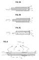
- FIG. 4illustrates the use of an aperture to block cladding mode light in an optical fiber.
- FIGS. 5A through 5Cillustrate various techniques for suppressing cladding mode light in an optical fiber.
- FIG. 6illustrates a combination of various techniques for suppressing stray light and cladding mode light in an optical fiber.
- FIG. 7illustrates the placement of a photodetector to detect cladding mode light in an optical fiber.
- FIG. 3shows a schematic representation of an exemplary embodiment of an optical fiber laser delivery system 30 in accordance with the present invention.
- the system 30delivers a laser beam 31 applied to an input port of the system via an optical fiber 10 to a work piece 310 .
- the laser beam 31is focused into the fiber core 11 of a fiber 10 with a plano-convex lens 32 .
- a portion 10 i of the fiber 10 proximate to the inputis bare; i.e., it does not include any outer layers of material.
- the bare fiber portion 10 iis held by a glass ferrule 33 which is transparent to any stray light and also strips off a portion of cladding mode light. Over at least a portion of its length, the bare fiber portion 10 i has a rough surface so that it further scatters off stray light and cladding mode light.
- the rough surfacecan be created in a variety of ways including, for example, sanding with a fine sand paper, sandblasting, chemical etching, and laser treatment.
- a first photodetector 36 facing the bare fiber portion 10 idetects the intensity of the light scattered off the bare fiber portion.
- a second photodetector 37 facing the input fiber enddetects the intensity of back-reflected cladding mode light.
- the output signals of the photodetectors 36 , 37are provided to a control unit 38 , which can control a laser control device 39 to disable or remove the laser beam 31 from the system.
- the laser control device 39can be a laser shutter or the like. In an exemplary embodiment, when the magnitude of one or more of the signals from the photodetectors 36 , 37 exceeds a predetermined threshold, the control unit triggers the laser control device 39 to disable the laser beam 31 .
- a second set of photodetectors 46 , 47 and a further control unit 48can optionally be provided for the fiber output port.
- an portion 10 o of the fiber 10 proximate to the output portis bare with a rough surface and is held by a second glass ferule 43 .
- Photodetector 46which faces the bare fiber portion 10 o , detects the intensity of the back-reflected light scattered off the bare fiber portion.
- Photodetector 47which faces the output fiber end, detects the intensity of the forward propagating cladding mode light.
- the further controller 48can control a further laser control device 49 (e.g., a laser shutter or the like) to disable or remove the laser beam from the system, or it can control the laser control device 39 in conjunction with the controller 38 .
- the controllers 38 and 48can also be replaced by a single controller to which all of the sensor signals are provided and which controls the laser control device 39 and/or the further laser control device 49 .
- any subset of the sensors 36 , 37 , 46 and 47can be used by a controller to control the laser control device 39 and/or the further laser control device 49 .
- the present inventionprovides several passive techniques for suppressing the cladding mode light propagating in a fiber, some of which have been illustrated in the arrangement of FIG. 3 .
- a first such techniqueis illustrated in FIG. 4 which shows the arrangement of a plate 40 with an aperture 45 between the injection light beam and the fiber 10 .
- the aperture 45allows the light beam to pass to the fiber core 11 , but blocks the light or changes the direction of the light which otherwise would be incident on the cladding 12 .
- the plate 40can be opaque (e.g., metal) or substantially transparent (e.g., glass). Opaque materials, however, are more susceptible to damage at high laser powers.
- the dimensions of the aperture 45 and the spacing between the aperture and the fiber 10can be selected so that light that would otherwise be directly incident on the cladding 12 will be deflected by the aperture 45 so that it does not enter the cladding or enters the cladding at an angle that causes the light to be quickly dissipated.
- Another approach for suppressing the cladding mode light propagating in a fiber in accordance with the present inventionentails treatment of the fiber end upon which the light beam is incident. Three exemplary fiber end treatments are illustrated in FIGS. 5A through 5C .
- the cladding 12 at the end of the fiber upon which the light beam is incident(the “incident end”) is made irregular or roughened by physical or chemical means, so that any light incident on this area is immediately scattered.
- the cladding 12 at the incident end of the fiberis beveled so that any light entering the cladding cannot satisfy the total reflection condition, thereby preventing its propagation.
- FIG. 6Another technique for suppressing cladding mode light propagation in a fiber is illustrated in FIG. 6 in which a glass ferrule 65 is used to hold a bared portion of the fiber (see also FIG. 3 ).
- Glass ferruleswith a wide variety of thicknesses and lengths are available.
- the ferrulesare typically made of fused silica or the same materials used to make various fibers.
- the glass ferrulealso helps to strip off the cladding mode light because the refraction index of the ferrule is larger or close to that of the fiber cladding. The longer the ferrule is, the greater the cladding mode light attenuation.
- FIG. 6also illustrates another technique for suppressing cladding mode light propagation which is to provide a rough surface on a portion 12 a of the outer surface of the cladding 12 of the bare fiber.
- the rough surfacecan scatter off a great portion of cladding mode light.
- the rough surfacecan be made by grinding or other physical or chemical methods.
- the intensity of stray light or cladding mode lightcan be significantly reduced before reaching the fiber outer layer joint points, so the risk of fiber failures can be greatly lowered.
- These techniquescan be applied at either or both of the input and output fiber connections or any other fiber junctions.
- the present inventionalso provides active techniques for protecting fiber.
- photodetector sensorsprovide feedback to an active control unit for protecting the fiber from damage and ensuring beam delivery with good performance.
- Photodetectorscan be are arranged to detect scattered stray light, cladding mode light, and/or back reflected cladding light.
- a photodetector 67is placed in the vicinity of a fiber connector facing an incoming beam, which can be the injected laser beam or the back reflected beam.
- the photodetector 67measures the intensity of the scattered light, which includes the combination of stray light and cladding mode light.
- the scattering sourcecan be the fiber end, the fiber holder, the bare fiber side surface, or the junction point.
- the photodetector device 67can also be a fiber-guided photodetector.
- the photodetector signalis sent to a control unit. If there is a noticeable fiber misalignment or back reflection, the scattered light intensity will increase.
- the average photodetector signalis proportional to the average scattered light intensity, which is generally an increasing function of the risk of fiber failure and a decreasing function of fiber couple efficiency.
- the control unitcan analyze the risk of fiber failures and the fiber coupling performance based on the sensor signal, and then can control laser shutters or other active components to prevent or reduce the risk of failures.
- the back reflected light beamcarries different power fluctuations at different stages of processing. As the processing of the work piece progresses, the characteristics of the back reflected light beam will change. Particularly when the laser is operated under pulsed conditions, the back reflected laser pulse will exhibit different “signatures” at different processing stages.
- the control unitcan analyze the photodetector signals and accordingly determine the current processing status of the work piece.
- the photodetector 37 at the injection endmonitors the injection condition while the photodetector 47 at the output end is responsible for monitoring the back reflected signals.
- Using photodetectors at both the injection and output ends of the laser delivery fiberprovides greater flexibility and options for the implementation of control functions, as opposed to having a photodetector at just one of the ends.
- cladding mode lighttravels in both the fiber cladding 12 and the fiber core 11 from one end of the fiber to the other.
- a significant portion of the cladding mode lightemerges from the output end of the fiber and then diverges in the air with an angle larger than the minimum acceptable angle of the fiber mode light. Therefore, the cladding mode light is clearly separated from the fiber mode light by the fiber NA boundary.
- the cladding mode light at the output portcan thus be detected by a photodetector.
- the backward transmitted cladding mode lightcan also be detected at the input port.
- photodetectorscan be arranged to face the exiting cladding mode light or to face an intermediate surface to detected the reflected or scattered cladding mode light signal.
Landscapes
- Physics & Mathematics (AREA)
- Optics & Photonics (AREA)
- Engineering & Computer Science (AREA)
- Plasma & Fusion (AREA)
- Mechanical Engineering (AREA)
- General Physics & Mathematics (AREA)
- Chemical & Material Sciences (AREA)
- Analytical Chemistry (AREA)
- Optical Couplings Of Light Guides (AREA)
Abstract
Description
with n0and n1being the refractive index of the
Claims (16)
Priority Applications (1)
| Application Number | Priority Date | Filing Date | Title |
|---|---|---|---|
| US10/895,238US7146073B2 (en) | 2004-07-19 | 2004-07-19 | Fiber delivery system with enhanced passive fiber protection and active monitoring |
Applications Claiming Priority (1)
| Application Number | Priority Date | Filing Date | Title |
|---|---|---|---|
| US10/895,238US7146073B2 (en) | 2004-07-19 | 2004-07-19 | Fiber delivery system with enhanced passive fiber protection and active monitoring |
Publications (2)
| Publication Number | Publication Date |
|---|---|
| US20060013532A1 US20060013532A1 (en) | 2006-01-19 |
| US7146073B2true US7146073B2 (en) | 2006-12-05 |
Family
ID=35599519
Family Applications (1)
| Application Number | Title | Priority Date | Filing Date |
|---|---|---|---|
| US10/895,238Expired - LifetimeUS7146073B2 (en) | 2004-07-19 | 2004-07-19 | Fiber delivery system with enhanced passive fiber protection and active monitoring |
Country Status (1)
| Country | Link |
|---|---|
| US (1) | US7146073B2 (en) |
Cited By (32)
| Publication number | Priority date | Publication date | Assignee | Title |
|---|---|---|---|---|
| US20070003288A1 (en)* | 2005-06-30 | 2007-01-04 | Xiaolin Tong | Bidirectional HDCP transmission module using single optical fiber |
| US20070242062A1 (en)* | 2006-04-18 | 2007-10-18 | Yong Guo | EDID pass through via serial channel |
| US20070280282A1 (en)* | 2006-06-05 | 2007-12-06 | Tzeng Shing-Wu P | Indoor digital multimedia networking |
| US20070286600A1 (en)* | 2006-06-09 | 2007-12-13 | Owlink Technology, Inc. | Universal IR Repeating over Optical Fiber |
| US20070292135A1 (en)* | 2006-06-09 | 2007-12-20 | Yong Guo | Integrated remote control signaling |
| US20080193093A1 (en)* | 2007-02-12 | 2008-08-14 | Furukawa Electric North America Inc | Optical fiber configuration for dissipating stray light |
| US20080291432A1 (en)* | 2007-04-26 | 2008-11-27 | Christopher Horvath | System and method for monitoring the coupling efficiency of a fiber-optic surgical system |
| US20080291074A1 (en)* | 2007-05-22 | 2008-11-27 | Owlink Technology, Inc. | Universal Remote Control Device |
| US20090154512A1 (en)* | 2007-12-17 | 2009-06-18 | Jds Uniphase Corporation, State Of Incorporation: Delaware | Method And Device For Monitoring Light |
| US20090202201A1 (en)* | 2008-02-13 | 2009-08-13 | Avago Technologies Fiber Ip Pte, Ltd. | Mode selective fiber stub, a transmitter optical subassembly that incorporates the stub and methods for making the mode selective fiber stub |
| US20100163537A1 (en)* | 2007-04-04 | 2010-07-01 | Mitsubishi Electric Corporation | Apparatus and method for laser machining |
| US20100183258A1 (en)* | 2009-01-20 | 2010-07-22 | Chi-Wai Chow | Fiber sensing system with self-detection mechanism |
| US20110122401A1 (en)* | 2008-05-29 | 2011-05-26 | Panduit Corp | Method and Apparatus For Verifying the Termination Quality of an Optical Fiber Interface in a Fiber Optic Cable Connector |
| US8027555B1 (en) | 2010-06-30 | 2011-09-27 | Jds Uniphase Corporation | Scalable cladding mode stripper device |
| DE102011089482A1 (en) | 2011-12-21 | 2013-06-27 | Jenoptik Laser Gmbh | Laser with monitored fiber optic path |
| US20150021303A1 (en)* | 2012-01-18 | 2015-01-22 | Amada Company, Limited | Laser machining device and laser oscillation control method |
| US8988669B2 (en) | 2013-04-23 | 2015-03-24 | Jds Uniphase Corporation | Power monitor for optical fiber using background scattering |
| US20180059343A1 (en)* | 2014-08-01 | 2018-03-01 | Nlight Photonics Corporation | Back-reflection protection and monitoring in fiber and fiber-delivered lasers |
| US20180138654A1 (en)* | 2016-11-16 | 2018-05-17 | Fanuc Corporation | Laser device |
| US10295845B2 (en) | 2016-09-29 | 2019-05-21 | Nlight, Inc. | Adjustable beam characteristics |
| US10434600B2 (en) | 2015-11-23 | 2019-10-08 | Nlight, Inc. | Fine-scale temporal control for laser material processing |
| US10520671B2 (en) | 2015-07-08 | 2019-12-31 | Nlight, Inc. | Fiber with depressed central index for increased beam parameter product |
| US10535973B2 (en) | 2015-01-26 | 2020-01-14 | Nlight, Inc. | High-power, single-mode fiber sources |
| US10732439B2 (en) | 2016-09-29 | 2020-08-04 | Nlight, Inc. | Fiber-coupled device for varying beam characteristics |
| US10730785B2 (en) | 2016-09-29 | 2020-08-04 | Nlight, Inc. | Optical fiber bending mechanisms |
| US10768433B2 (en) | 2015-09-24 | 2020-09-08 | Nlight, Inc. | Beam parameter product (bpp) control by varying fiber-to-fiber angle |
| CN112334807A (en)* | 2018-06-25 | 2021-02-05 | 通快激光有限责任公司 | Optical fiber cable with a cladding light sensor and associated calibration, test and monitoring device |
| US10971885B2 (en) | 2014-06-02 | 2021-04-06 | Nlight, Inc. | Scalable high power fiber laser |
| US10971884B2 (en) | 2015-03-26 | 2021-04-06 | Nlight, Inc. | Fiber source with cascaded gain stages and/or multimode delivery fiber with low splice loss |
| US11179807B2 (en) | 2015-11-23 | 2021-11-23 | Nlight, Inc. | Fine-scale temporal control for laser material processing |
| US20240019651A1 (en)* | 2022-07-12 | 2024-01-18 | Globalfoundries U.S. Inc. | Scattering light-based monitor for photonic integrated circuit, monitoring system and monitoring method |
| US12442996B2 (en)* | 2022-07-12 | 2025-10-14 | Globalfoundries U.S. Inc. | Scattering light-based monitor for photonic integrated circuit, monitoring system and monitoring method |
Families Citing this family (22)
| Publication number | Priority date | Publication date | Assignee | Title |
|---|---|---|---|---|
| US7371019B2 (en)* | 2004-12-13 | 2008-05-13 | Nufern | Method and apparatus for sensing light |
| WO2007048180A1 (en)* | 2005-10-24 | 2007-05-03 | Rpo Pty Limited | Improved optical elements for waveguide-based optical touch screens |
| US7509004B2 (en)* | 2006-10-31 | 2009-03-24 | Avago Technologies Fiber Ip (Singapore) Pte. Ltd. | Apertured fiber optic stub for control of multi-mode launch condition |
| GB2458304A (en)* | 2008-03-13 | 2009-09-16 | Gsi Group Ltd | Process Monitoring |
| BRPI0806638B1 (en)* | 2008-11-28 | 2017-03-14 | Faculdades Católicas Mantenedora Da Pontifícia Univ Católica Do Rio De Janeiro - Puc Rio | laser drilling process |
| US8111385B2 (en)* | 2009-01-26 | 2012-02-07 | The Boeing Company | Quantum dot-mediated optical fiber information retrieval systems and methods of use |
| DE102009046464A1 (en)* | 2009-11-06 | 2011-05-12 | Robert Bosch Gmbh | light source |
| SE536579C2 (en)* | 2011-12-19 | 2014-03-04 | Optoskand Ab | Device for monitoring the process performance of a laser system with an optical high power fiber cable |
| JP6129613B2 (en)* | 2013-03-27 | 2017-05-17 | 三菱電線工業株式会社 | Optical connector and optical fiber cable using the same |
| US9547143B2 (en)* | 2013-05-09 | 2017-01-17 | Laser Mechanisms, Inc. | Fiber optic laser alignment tool |
| WO2015118829A1 (en)* | 2014-02-05 | 2015-08-13 | パナソニックIpマネジメント株式会社 | Laser machining device |
| JP6723695B2 (en)* | 2015-07-08 | 2020-07-15 | 株式会社フジクラ | Optical power monitor device and fiber laser device |
| JP6694754B2 (en) | 2016-05-16 | 2020-05-20 | 株式会社フジクラ | Laser device and laser system |
| JP6807662B2 (en)* | 2016-06-14 | 2021-01-06 | 浜松ホトニクス株式会社 | Method for manufacturing laser oscillator and excitation light detection structure |
| DE102017102885B4 (en)* | 2017-02-14 | 2019-05-02 | Harting Electric Gmbh & Co. Kg | Optical connector, connector module and method for detecting signal loss in an optical connector module |
| JP6868796B2 (en)* | 2017-05-10 | 2021-05-12 | パナソニックIpマネジメント株式会社 | Laser device |
| EP3683000B1 (en)* | 2017-09-11 | 2023-05-24 | Panasonic Intellectual Property Management Co., Ltd. | Laser device |
| JP6802234B2 (en) | 2018-10-12 | 2020-12-16 | ファナック株式会社 | Laser oscillator monitoring and control system |
| CN113615013A (en)* | 2019-03-11 | 2021-11-05 | 株式会社藤仓 | Optical connector and laser device provided with same |
| US11199671B2 (en)* | 2020-04-21 | 2021-12-14 | Hewlett Packard Enterprise Development Lp | Glass-as-a-platform (GaaP)-based photonic assemblies comprising shaped glass plates |
| WO2024171538A1 (en)* | 2023-02-17 | 2024-08-22 | 株式会社フジクラ | Laser device |
| DE102023136333A1 (en)* | 2023-12-21 | 2025-06-26 | TRUMPF Lasersystems for Semiconductor Manufacturing SE | Active partially destructible laser protection device, assembly and laser system therewith, and method for operating the same |
Citations (15)
| Publication number | Priority date | Publication date | Assignee | Title |
|---|---|---|---|---|
| US4716288A (en)* | 1980-11-01 | 1987-12-29 | Asahi Kogaku Kogyo Kabushiki Kaisha | Security device for detecting defects in transmitting fiber |
| US4781428A (en)* | 1984-07-11 | 1988-11-01 | Stc Plc | Devices and methods for selectively tapping optical energy from an optical fibre |
| US4812641A (en) | 1987-02-03 | 1989-03-14 | General Electric Company | High power optical fiber failure detection system |
| US4883054A (en)* | 1987-12-09 | 1989-11-28 | Fuller Research Corporation | Optical fiber break detector |
| US4887879A (en)* | 1988-01-25 | 1989-12-19 | The Trustees Of Columbia University In The City Of New York | Fiber optic tap |
| US5012087A (en)* | 1989-04-13 | 1991-04-30 | General Electric Company | Fiber optic safety system |
| US5080506A (en)* | 1988-05-20 | 1992-01-14 | Raynet Corp. | Optical fiber tap for monitoring laser input power |
| US5159402A (en)* | 1990-03-26 | 1992-10-27 | General Electric Company | Optical sensor safety system for monitoring laser crystals and optical components |
| US5219345A (en)* | 1990-03-30 | 1993-06-15 | Health Research, Inc. | Backscatter monitoring system |
| US5251001A (en)* | 1991-11-18 | 1993-10-05 | Teradyne, Inc. | Reflected optical power fiber test system |
| US5319195A (en) | 1991-04-02 | 1994-06-07 | Lumonics Ltd. | Laser system method and apparatus for performing a material processing operation and for indicating the state of the operation |
| US5966206A (en)* | 1996-10-10 | 1999-10-12 | Tyco Submarine Systems Ltd. | Interlocked high power fiber system using OTDR |
| US6046802A (en)* | 1998-11-16 | 2000-04-04 | General Electric Company | Optical element surface monitoring system and method |
| US20050002607A1 (en)* | 2002-11-12 | 2005-01-06 | Toptica Photonics Ag | Method for manufacturing of an optical fiber with a decoupling interface for scattered light, use of an optical fiber and device for monitoring of the light power guided through an optical fiber |
| US20050025418A1 (en)* | 2002-02-22 | 2005-02-03 | Brown Joe D. | Apparatus and method for diffusing laser energy that fails to couple into small core fibers, and for reducing coupling to the cladding of the fiber |
- 2004
- 2004-07-19USUS10/895,238patent/US7146073B2/ennot_activeExpired - Lifetime
Patent Citations (15)
| Publication number | Priority date | Publication date | Assignee | Title |
|---|---|---|---|---|
| US4716288A (en)* | 1980-11-01 | 1987-12-29 | Asahi Kogaku Kogyo Kabushiki Kaisha | Security device for detecting defects in transmitting fiber |
| US4781428A (en)* | 1984-07-11 | 1988-11-01 | Stc Plc | Devices and methods for selectively tapping optical energy from an optical fibre |
| US4812641A (en) | 1987-02-03 | 1989-03-14 | General Electric Company | High power optical fiber failure detection system |
| US4883054A (en)* | 1987-12-09 | 1989-11-28 | Fuller Research Corporation | Optical fiber break detector |
| US4887879A (en)* | 1988-01-25 | 1989-12-19 | The Trustees Of Columbia University In The City Of New York | Fiber optic tap |
| US5080506A (en)* | 1988-05-20 | 1992-01-14 | Raynet Corp. | Optical fiber tap for monitoring laser input power |
| US5012087A (en)* | 1989-04-13 | 1991-04-30 | General Electric Company | Fiber optic safety system |
| US5159402A (en)* | 1990-03-26 | 1992-10-27 | General Electric Company | Optical sensor safety system for monitoring laser crystals and optical components |
| US5219345A (en)* | 1990-03-30 | 1993-06-15 | Health Research, Inc. | Backscatter monitoring system |
| US5319195A (en) | 1991-04-02 | 1994-06-07 | Lumonics Ltd. | Laser system method and apparatus for performing a material processing operation and for indicating the state of the operation |
| US5251001A (en)* | 1991-11-18 | 1993-10-05 | Teradyne, Inc. | Reflected optical power fiber test system |
| US5966206A (en)* | 1996-10-10 | 1999-10-12 | Tyco Submarine Systems Ltd. | Interlocked high power fiber system using OTDR |
| US6046802A (en)* | 1998-11-16 | 2000-04-04 | General Electric Company | Optical element surface monitoring system and method |
| US20050025418A1 (en)* | 2002-02-22 | 2005-02-03 | Brown Joe D. | Apparatus and method for diffusing laser energy that fails to couple into small core fibers, and for reducing coupling to the cladding of the fiber |
| US20050002607A1 (en)* | 2002-11-12 | 2005-01-06 | Toptica Photonics Ag | Method for manufacturing of an optical fiber with a decoupling interface for scattered light, use of an optical fiber and device for monitoring of the light power guided through an optical fiber |
Cited By (52)
| Publication number | Priority date | Publication date | Assignee | Title |
|---|---|---|---|---|
| US20070003288A1 (en)* | 2005-06-30 | 2007-01-04 | Xiaolin Tong | Bidirectional HDCP transmission module using single optical fiber |
| US20070242062A1 (en)* | 2006-04-18 | 2007-10-18 | Yong Guo | EDID pass through via serial channel |
| US20070280282A1 (en)* | 2006-06-05 | 2007-12-06 | Tzeng Shing-Wu P | Indoor digital multimedia networking |
| US20070292135A1 (en)* | 2006-06-09 | 2007-12-20 | Yong Guo | Integrated remote control signaling |
| US20070286600A1 (en)* | 2006-06-09 | 2007-12-13 | Owlink Technology, Inc. | Universal IR Repeating over Optical Fiber |
| US20080193093A1 (en)* | 2007-02-12 | 2008-08-14 | Furukawa Electric North America Inc | Optical fiber configuration for dissipating stray light |
| US7437046B2 (en) | 2007-02-12 | 2008-10-14 | Furukawa Electric North America, Inc. | Optical fiber configuration for dissipating stray light |
| US7787733B2 (en) | 2007-02-12 | 2010-08-31 | Furukawa Electric North America, Inc. | Optical fiber configuration for dissipating stray light |
| US7760978B2 (en) | 2007-02-12 | 2010-07-20 | DFS Fitel LLC | Optical fiber configuration for dissipating stray light |
| US20090016681A1 (en)* | 2007-02-12 | 2009-01-15 | Digiovanni David John | Optical fiber configuration for dissipating stray light |
| US20090067795A1 (en)* | 2007-02-12 | 2009-03-12 | Digiovanni David John | Optical fiber configuration for dissipating stray light |
| US20100163537A1 (en)* | 2007-04-04 | 2010-07-01 | Mitsubishi Electric Corporation | Apparatus and method for laser machining |
| US20080291432A1 (en)* | 2007-04-26 | 2008-11-27 | Christopher Horvath | System and method for monitoring the coupling efficiency of a fiber-optic surgical system |
| US8150261B2 (en) | 2007-05-22 | 2012-04-03 | Owlink Technology, Inc. | Universal remote control device |
| US20080291074A1 (en)* | 2007-05-22 | 2008-11-27 | Owlink Technology, Inc. | Universal Remote Control Device |
| US20090154512A1 (en)* | 2007-12-17 | 2009-06-18 | Jds Uniphase Corporation, State Of Incorporation: Delaware | Method And Device For Monitoring Light |
| US7957438B2 (en)* | 2007-12-17 | 2011-06-07 | Jds Uniphase Corporation | Method and device for monitoring light |
| US20090202201A1 (en)* | 2008-02-13 | 2009-08-13 | Avago Technologies Fiber Ip Pte, Ltd. | Mode selective fiber stub, a transmitter optical subassembly that incorporates the stub and methods for making the mode selective fiber stub |
| US7711220B2 (en)* | 2008-02-13 | 2010-05-04 | Avago Technologies Fiber Ip (Singapore) Pte. Ltd. | Mode selective fiber stub, a transmitter optical subassembly that incorporates the stub and methods for making the mode selective fiber stub |
| US20110122401A1 (en)* | 2008-05-29 | 2011-05-26 | Panduit Corp | Method and Apparatus For Verifying the Termination Quality of an Optical Fiber Interface in a Fiber Optic Cable Connector |
| US7925126B2 (en) | 2009-01-20 | 2011-04-12 | National Chiao Tung University | Fiber sensing system with self-detection mechanism |
| US20100183258A1 (en)* | 2009-01-20 | 2010-07-22 | Chi-Wai Chow | Fiber sensing system with self-detection mechanism |
| US8027555B1 (en) | 2010-06-30 | 2011-09-27 | Jds Uniphase Corporation | Scalable cladding mode stripper device |
| DE102011089482A1 (en) | 2011-12-21 | 2013-06-27 | Jenoptik Laser Gmbh | Laser with monitored fiber optic path |
| WO2013091851A1 (en) | 2011-12-21 | 2013-06-27 | Jenoptik Laser Gmbh | Laser having a monitored optical fiber section |
| US20150021303A1 (en)* | 2012-01-18 | 2015-01-22 | Amada Company, Limited | Laser machining device and laser oscillation control method |
| US10478923B2 (en)* | 2012-01-18 | 2019-11-19 | Amada Company, Limited | Laser machining device and laser oscillation control method |
| US8988669B2 (en) | 2013-04-23 | 2015-03-24 | Jds Uniphase Corporation | Power monitor for optical fiber using background scattering |
| US10971885B2 (en) | 2014-06-02 | 2021-04-06 | Nlight, Inc. | Scalable high power fiber laser |
| US20180059343A1 (en)* | 2014-08-01 | 2018-03-01 | Nlight Photonics Corporation | Back-reflection protection and monitoring in fiber and fiber-delivered lasers |
| US10310201B2 (en)* | 2014-08-01 | 2019-06-04 | Nlight, Inc. | Back-reflection protection and monitoring in fiber and fiber-delivered lasers |
| US10901162B2 (en) | 2014-08-01 | 2021-01-26 | Nlight, Inc. | Back-reflection protection and monitoring in fiber and fiber-delivered lasers |
| US10535973B2 (en) | 2015-01-26 | 2020-01-14 | Nlight, Inc. | High-power, single-mode fiber sources |
| US10916908B2 (en) | 2015-01-26 | 2021-02-09 | Nlight, Inc. | High-power, single-mode fiber sources |
| US10971884B2 (en) | 2015-03-26 | 2021-04-06 | Nlight, Inc. | Fiber source with cascaded gain stages and/or multimode delivery fiber with low splice loss |
| US10520671B2 (en) | 2015-07-08 | 2019-12-31 | Nlight, Inc. | Fiber with depressed central index for increased beam parameter product |
| US11719948B2 (en) | 2015-09-24 | 2023-08-08 | Nlight, Inc. | Beam parameter product (BPP) control by varying fiber-to-fiber angle |
| US10768433B2 (en) | 2015-09-24 | 2020-09-08 | Nlight, Inc. | Beam parameter product (bpp) control by varying fiber-to-fiber angle |
| US11794282B2 (en) | 2015-11-23 | 2023-10-24 | Nlight, Inc. | Fine-scale temporal control for laser material processing |
| US11331756B2 (en) | 2015-11-23 | 2022-05-17 | Nlight, Inc. | Fine-scale temporal control for laser material processing |
| US11179807B2 (en) | 2015-11-23 | 2021-11-23 | Nlight, Inc. | Fine-scale temporal control for laser material processing |
| US10434600B2 (en) | 2015-11-23 | 2019-10-08 | Nlight, Inc. | Fine-scale temporal control for laser material processing |
| US10732439B2 (en) | 2016-09-29 | 2020-08-04 | Nlight, Inc. | Fiber-coupled device for varying beam characteristics |
| US10295845B2 (en) | 2016-09-29 | 2019-05-21 | Nlight, Inc. | Adjustable beam characteristics |
| US10730785B2 (en) | 2016-09-29 | 2020-08-04 | Nlight, Inc. | Optical fiber bending mechanisms |
| US10663767B2 (en) | 2016-09-29 | 2020-05-26 | Nlight, Inc. | Adjustable beam characteristics |
| US10637205B2 (en)* | 2016-11-16 | 2020-04-28 | Fanuc Corporation | Laser device |
| US20180138654A1 (en)* | 2016-11-16 | 2018-05-17 | Fanuc Corporation | Laser device |
| CN112334807A (en)* | 2018-06-25 | 2021-02-05 | 通快激光有限责任公司 | Optical fiber cable with a cladding light sensor and associated calibration, test and monitoring device |
| US11662533B2 (en)* | 2018-06-25 | 2023-05-30 | Trumpf Laser Gmbh | Optical cable with a cladding light sensor and associated adjustment, test and monitoring apparatuses |
| US20240019651A1 (en)* | 2022-07-12 | 2024-01-18 | Globalfoundries U.S. Inc. | Scattering light-based monitor for photonic integrated circuit, monitoring system and monitoring method |
| US12442996B2 (en)* | 2022-07-12 | 2025-10-14 | Globalfoundries U.S. Inc. | Scattering light-based monitor for photonic integrated circuit, monitoring system and monitoring method |
Also Published As
| Publication number | Publication date |
|---|---|
| US20060013532A1 (en) | 2006-01-19 |
Similar Documents
| Publication | Publication Date | Title |
|---|---|---|
| US7146073B2 (en) | Fiber delivery system with enhanced passive fiber protection and active monitoring | |
| JP6660063B2 (en) | Apparatus for monitoring the processing performance of laser systems using high power fiber optic cables | |
| US7957438B2 (en) | Method and device for monitoring light | |
| JP6564418B2 (en) | Optical power monitor device and laser device | |
| KR102162811B1 (en) | Low-mode high power fiber combiner | |
| US12235467B2 (en) | Splice with cladding mode light stripping | |
| EP0151909B1 (en) | Optical fibre | |
| TWI493237B (en) | Coated optical fibers and related apparatuses, links, and methods for providing optical attenuation | |
| US8724945B2 (en) | High power fiber laser system with integrated termination block | |
| KR102217718B1 (en) | Ultra-high power fiber laser system with multimode-multimode fiber combiner | |
| CN106030362B (en) | Optical power monitoring device, fiber laser and optical power monitoring method | |
| US6898219B2 (en) | Apparatus and method for VCSEL monitoring using scattering and reflecting of emitted light | |
| US7058267B2 (en) | Method for manufacturing of an optical fiber with a decoupling interface for scattered light, use of an optical fiber and device for monitoring of the light power guided through an optical fiber | |
| US4950046A (en) | Fiber optic coupler | |
| CN109244816B (en) | Optical fiber combiner with power monitoring device and power monitoring method thereof | |
| US7162114B2 (en) | Optical energy switching device and method | |
| CN109844588B (en) | Splice for stripping cladding mode light | |
| JPS5979137A (en) | Detection for disconnection of optical fiber | |
| GB2332050A (en) | Fibre-optic energy transmission monitor | |
| CA2363830A1 (en) | Optical coupling device with anisotropic light-guiding member | |
| CA1258787A (en) | Fiber optic coupler | |
| Sottini et al. | Monitoring of laser delivery systems | |
| JPH0421824A (en) | Excessive light protection method for optical circuits and photosensitive light attenuation element |
Legal Events
| Date | Code | Title | Description |
|---|---|---|---|
| AS | Assignment | Owner name:QUANTRONIX CORPORATION, NEW YORK Free format text:ASSIGNMENT OF ASSIGNORS INTEREST;ASSIGNOR:WAN, XIAOKE;REEL/FRAME:016990/0056 Effective date:20051101 | |
| STCF | Information on status: patent grant | Free format text:PATENTED CASE | |
| FEPP | Fee payment procedure | Free format text:PAYOR NUMBER ASSIGNED (ORIGINAL EVENT CODE: ASPN); ENTITY STATUS OF PATENT OWNER: LARGE ENTITY Free format text:PAYER NUMBER DE-ASSIGNED (ORIGINAL EVENT CODE: RMPN); ENTITY STATUS OF PATENT OWNER: LARGE ENTITY | |
| FPAY | Fee payment | Year of fee payment:4 | |
| AS | Assignment | Owner name:THE BANK OF NEW YORK MELLON TRUST COMPANY, N.A., A Free format text:SECURITY AGREEMENT;ASSIGNORS:GSI GROUP INC.;GSI GROUP CORPORATION;MES INTERNATIONAL INC.;AND OTHERS;REEL/FRAME:024755/0537 Effective date:20100723 | |
| AS | Assignment | Owner name:CONTINUUM ELECTRO-OPTICS INC., MASSACHUSETTS Free format text:RELEASE;ASSIGNOR:THE BANK OF NEW YORK MELLON TRUST COMPANY, N.A.;REEL/FRAME:027127/0368 Effective date:20111019 Owner name:EXCEL TECHNOLOGY INC., MASSACHUSETTS Free format text:RELEASE;ASSIGNOR:THE BANK OF NEW YORK MELLON TRUST COMPANY, N.A.;REEL/FRAME:027127/0368 Effective date:20111019 Owner name:CONTROL LASER CORPORATION (D/B/A BAUBLYS CONTROL L Free format text:RELEASE;ASSIGNOR:THE BANK OF NEW YORK MELLON TRUST COMPANY, N.A.;REEL/FRAME:027127/0368 Effective date:20111019 Owner name:QUANTRONIX CORPORATION, MASSACHUSETTS Free format text:RELEASE;ASSIGNOR:THE BANK OF NEW YORK MELLON TRUST COMPANY, N.A.;REEL/FRAME:027127/0368 Effective date:20111019 Owner name:BANK OF AMERICA, N.A., MASSACHUSETTS Free format text:SECURITY AGREEMENT;ASSIGNORS:GSI GROUP INC.;GSI GROUP CORPORATION;REEL/FRAME:027128/0763 Effective date:20111019 Owner name:GSI GROUP CORPORATION, MASSACHUSETTS Free format text:RELEASE;ASSIGNOR:THE BANK OF NEW YORK MELLON TRUST COMPANY, N.A.;REEL/FRAME:027127/0368 Effective date:20111019 Owner name:MES INTERNATIONAL INC., MASSACHUSETTS Free format text:RELEASE;ASSIGNOR:THE BANK OF NEW YORK MELLON TRUST COMPANY, N.A.;REEL/FRAME:027127/0368 Effective date:20111019 Owner name:CAMBRIDGE TECHNOLOGY INC., MASSACHUSETTS Free format text:RELEASE;ASSIGNOR:THE BANK OF NEW YORK MELLON TRUST COMPANY, N.A.;REEL/FRAME:027127/0368 Effective date:20111019 Owner name:PHOTO RESEARCH INC., MASSACHUSETTS Free format text:RELEASE;ASSIGNOR:THE BANK OF NEW YORK MELLON TRUST COMPANY, N.A.;REEL/FRAME:027127/0368 Effective date:20111019 Owner name:MICROE SYSTEMS CORP., MASSACHUSETTS Free format text:RELEASE;ASSIGNOR:THE BANK OF NEW YORK MELLON TRUST COMPANY, N.A.;REEL/FRAME:027127/0368 Effective date:20111019 Owner name:SYNRAD INC., MASSACHUSETTS Free format text:RELEASE;ASSIGNOR:THE BANK OF NEW YORK MELLON TRUST COMPANY, N.A.;REEL/FRAME:027127/0368 Effective date:20111019 Owner name:GSI GROUP INC., MASSACHUSETTS Free format text:RELEASE;ASSIGNOR:THE BANK OF NEW YORK MELLON TRUST COMPANY, N.A.;REEL/FRAME:027127/0368 Effective date:20111019 Owner name:THE OPTICAL CORPORATION, MASSACHUSETTS Free format text:RELEASE;ASSIGNOR:THE BANK OF NEW YORK MELLON TRUST COMPANY, N.A.;REEL/FRAME:027127/0368 Effective date:20111019 | |
| AS | Assignment | Owner name:CONTINUUM ELECTRO-OPTICS, INC., CALIFORNIA Free format text:ASSIGNMENT OF ASSIGNORS INTEREST;ASSIGNOR:QUANTRONIX CORPORATION;REEL/FRAME:028361/0458 Effective date:20120501 | |
| AS | Assignment | Owner name:CONTINUUM ELECTRO-OPTICS, INC., CALIFORNIA Free format text:RELEASE OF SECURITY INTEREST;ASSIGNOR:BANK OF AMERICA, N.A.;REEL/FRAME:033341/0682 Effective date:20140715 | |
| FPAY | Fee payment | Year of fee payment:8 | |
| SULP | Surcharge for late payment | Year of fee payment:7 | |
| MAFP | Maintenance fee payment | Free format text:PAYMENT OF MAINTENANCE FEE, 12TH YEAR, LARGE ENTITY (ORIGINAL EVENT CODE: M1553) Year of fee payment:12 |