US7145753B1 - Head stack assembly with insulated wiring extending between actuator coil and actuator main body section disposed in lateral wiring protector extending from actuator body - Google Patents
Head stack assembly with insulated wiring extending between actuator coil and actuator main body section disposed in lateral wiring protector extending from actuator bodyDownload PDFInfo
- Publication number
- US7145753B1 US7145753B1US10/846,036US84603604AUS7145753B1US 7145753 B1US7145753 B1US 7145753B1US 84603604 AUS84603604 AUS 84603604AUS 7145753 B1US7145753 B1US 7145753B1
- Authority
- US
- United States
- Prior art keywords
- stack assembly
- head stack
- main body
- actuator
- body section
- Prior art date
- Legal status (The legal status is an assumption and is not a legal conclusion. Google has not performed a legal analysis and makes no representation as to the accuracy of the status listed.)
- Expired - Fee Related, expires
Links
- 230000001012protectorEffects0.000titleclaimsabstractdescription47
- 239000000463materialSubstances0.000claimsdescription9
- 239000007769metal materialSubstances0.000claimsdescription6
- 239000004033plasticSubstances0.000claimsdescription6
- 238000010276constructionMethods0.000description3
- 238000009434installationMethods0.000description2
- 239000000725suspensionSubstances0.000description2
- 239000004642PolyimideSubstances0.000description1
- 239000000853adhesiveSubstances0.000description1
- 230000001070adhesive effectEffects0.000description1
- 230000002452interceptive effectEffects0.000description1
- 229920001721polyimidePolymers0.000description1
Images


Classifications
- G—PHYSICS
- G11—INFORMATION STORAGE
- G11B—INFORMATION STORAGE BASED ON RELATIVE MOVEMENT BETWEEN RECORD CARRIER AND TRANSDUCER
- G11B5/00—Recording by magnetisation or demagnetisation of a record carrier; Reproducing by magnetic means; Record carriers therefor
- G11B5/48—Disposition or mounting of heads or head supports relative to record carriers ; arrangements of heads, e.g. for scanning the record carrier to increase the relative speed
- G11B5/54—Disposition or mounting of heads or head supports relative to record carriers ; arrangements of heads, e.g. for scanning the record carrier to increase the relative speed with provision for moving the head into or out of its operative position or across tracks
- G11B5/55—Track change, selection or acquisition by displacement of the head
- G11B5/5521—Track change, selection or acquisition by displacement of the head across disk tracks
- G—PHYSICS
- G11—INFORMATION STORAGE
- G11B—INFORMATION STORAGE BASED ON RELATIVE MOVEMENT BETWEEN RECORD CARRIER AND TRANSDUCER
- G11B5/00—Recording by magnetisation or demagnetisation of a record carrier; Reproducing by magnetic means; Record carriers therefor
- G11B5/48—Disposition or mounting of heads or head supports relative to record carriers ; arrangements of heads, e.g. for scanning the record carrier to increase the relative speed
- G11B5/4806—Disposition or mounting of heads or head supports relative to record carriers ; arrangements of heads, e.g. for scanning the record carrier to increase the relative speed specially adapted for disk drive assemblies, e.g. assembly prior to operation, hard or flexible disk drives
- G11B5/4853—Constructional details of the electrical connection between head and arm
- G—PHYSICS
- G11—INFORMATION STORAGE
- G11B—INFORMATION STORAGE BASED ON RELATIVE MOVEMENT BETWEEN RECORD CARRIER AND TRANSDUCER
- G11B5/00—Recording by magnetisation or demagnetisation of a record carrier; Reproducing by magnetic means; Record carriers therefor
- G11B5/48—Disposition or mounting of heads or head supports relative to record carriers ; arrangements of heads, e.g. for scanning the record carrier to increase the relative speed
- G11B5/4806—Disposition or mounting of heads or head supports relative to record carriers ; arrangements of heads, e.g. for scanning the record carrier to increase the relative speed specially adapted for disk drive assemblies, e.g. assembly prior to operation, hard or flexible disk drives
- G11B5/486—Disposition or mounting of heads or head supports relative to record carriers ; arrangements of heads, e.g. for scanning the record carrier to increase the relative speed specially adapted for disk drive assemblies, e.g. assembly prior to operation, hard or flexible disk drives with provision for mounting or arranging electrical conducting means or circuits on or along the arm assembly
Definitions
- the present inventionrelates generally to disk drives, and in, particular to a disk drive including a head stack assembly with insulated wiring extending between an actuator coil and an actuator main body section disposed in a lateral wiring protector extending from the actuator body.
- the typical hard disk driveincludes a head disk assembly (HDA) and a printed circuit board assembly (PCBA) attached to a disk drive base of the HDA.
- the head disk assemblyincludes at least one magnetic disk, a spindle motor for rotating the disk, and a head stack assembly (HSA).
- the spindle motorincludes a spindle motor hub that is rotatably attached to the disk drive base and supports a lowermost one of the disks.
- the head stack assemblyhas an actuator assembly having at least one air bearing slider, typically several, for reading and writing data from and to the disk. Each slider includes a transducer head for reading and writing data.
- the printed circuit board assemblyincludes a servo control system in the form of a disk controller for generating servo control signals.
- the head stack assemblyis controllably positioned in response to generated servo control signals from the disk controller. In so doing, the attached sliders are controllably moved relative to tracks disposed upon the disk for reading and writing operations.
- the head stack assemblyincludes an actuator assembly, at least one head gimbal assembly, and a flex circuit assembly.
- a conventional “rotary” or “swing-type” actuator assemblytypically includes an actuator having an actuator body. The actuator body is configured to rotate on a pivot assembly between limited positions about an axis of rotation.
- the actuator bodyincludes a main body section. One or more actuator arms extend from one opposite side of the main body section.
- a head gimbal assemblyis distally attached to each of the actuator arms.
- a head gimbal assemblyincludes an air bearing slider that is attached to a suspension with a gimbal. The suspension resiliently supports the air bearing slider above the tracks of the disk during operation of the disk drive facilitating the slider to “fly” above the disk.
- a coilis supported by a coil support that extends from an opposite side of the main body section.
- the coilis configured to interact with one or more permanent magnets to form a voice coil motor.
- the coilis disposed in electrical communication with the disk controller through a flex circuit assembly. Controlled movement of the head stack assembly is achieved by selectively energizing the coil with the generated servo control signals.
- the flex circuit assemblyis configured (1) to supply current to the actuator coil from the printed circuit board assembly and (2) to carry signals between the transducer heads and the printed circuit board assembly.
- the flex circuit assemblyincludes a flex cable (also referred to as a flex circuit cable or flex circuit), an integrated circuit device, and a cable connector.
- the flex cableincludes a plurality of conductive traces embedded within the flex cable that terminate at the cable connector which is electrically connected to the printed circuit board assembly.
- the flex cablefurther includes a base film and a cover which are typically formed of a polyimide material.
- the plurality of conductive tracesis disposed between the base and cover films. Insulated wiring extends along each actuator arm to each transducer head for transmitting data signals to and from the transducer heads. Such insulated wiring is connected to the flex cable.
- an electrical connectionis made between the coil and the conductive traces of the flex cable.
- Thistypically takes the form of a short segment that extends along a bottom surface of the actuator body.
- This electrical connectionmay take a variety of forms.
- a section of flex material similar in construction to the flex cablemay be used. Such a section would lie flat against the actuator main body section, and secured in place with an adhesive.
- Such flex materialis considered relatively expensive.
- insulated wiringmay be used which is considered to be relatively less expensive. However, because such wiring does not have a comparable flat profile like the flex material, there is a concern that during handing and installation of the actuator the insulated wiring may become dislodged or loosened thereby interfering with the intended electrical connection.
- a head stack assemblyfor a disk drive.
- the head stack assemblyincludes an actuator body defining an axis of rotation.
- the actuator bodyincludes a main body section and a coil support portion extending from the main body section.
- the head stack assemblyfurther includes an actuator coil supported by the coil support portion.
- the head stack assemblyfurther includes insulated wiring extending between the actuator coil and the main body section in a direction orthogonal to the axis of rotation.
- the head stack assemblyfurther includes a lateral wiring protector disposed laterally about the insulated wiring and extending from the main body section in a direction parallel to the axis of rotation.
- the lateral wiring protectorincludes an open channel with the insulated wiring disposed within the open channel.
- the lateral wiring protectormay be integrally formed with the main body section.
- the lateral wiring protector and the actuator bodymay be formed of a metal material.
- the lateral wiring protectormay be a punched feature formed in the main body section.
- the lateral wiring protectormay be a stamped feature formed in the main body section.
- the lateral wiring protectormay be a machined feature formed in the main body section.
- the lateral wiring protectormay include multiple protrusions extending from the main body section. The open channel may be formed between the multiple protrusions.
- the insulated wiringmay be interwoven between the multiple protrusions.
- the insulated wiringmay be glued to the main body section.
- the insulated wiringmay be glued to the lateral wiring protector.
- the lateral wiring protectormay be formed of a plastic material.
- the lateral wiring protectormay be formed of overmolded plastic and the main body section may be formed of a metal material.
- the open channelmay take the form of an elongate depression with the insulated wiring disposed in the elongate depression.
- the actuator coil and the insulated wiringmay be integrally formed.
- the open channelmay define a depth at least half a thickness of the insulated wiring.
- the disk driveincludes a disk drive base and the head stack assembly rotatably coupled to the disk drive base.
- the head stack assemblyis as described above.
- FIG. 1is an exploded perspective view of a disk drive in accordance with an aspect of the present invention
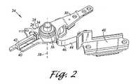
- FIG. 2is an enlarged top perspective view of a head stack assembly of FIG. 1 ;
- FIG. 3is a bottom perspective view of the head stack assembly FIG. 2 including the lateral wiring protector with insulated wiring;
- FIG. 4is the head stack assembly of FIG. 3 , however, without the insulated wiring shown;
- FIG. 5is a view similar to that of FIG. 3 , however, according to another embodiment
- FIG. 6is the head stack assembly of FIG. 5 , however, without the insulated wiring shown with the lateral wiring protector.
- FIG. 7is a view similar to that of FIG. 3 , however, according to another embodiment.
- FIG. 8is the head stack assembly of FIG. 7 , however, without the insulated wiring shown with the lateral wiring protector.
- FIGS. 1–8illustrate a head stack assembly and a disk drive in accordance with aspects of the present invention.
- the disk drive 10includes a head disk assembly (HDA) 12 and a printed circuit board assembly (PCBA) 14 .
- the head disk assembly 12includes a disk drive housing having disk drive housing members, such as a disk drive base 16 and a cover 18 .
- the disk drive base 16 and the cover 18collectively house a magnetic disk 20 .
- the disk 20contains a plurality of tracks for storing data.
- the head disk assembly 12further includes a spindle motor 22 for rotating the disk 20 .
- the head disk assembly 12further includes a head stack assembly 24 rotatably attached to the disk drive base 16 in operable communication with the disk 20 .
- the head stack assembly 24includes a rotary actuator 26 .
- the actuator 26includes an actuator body 28 and an actuator arm 30 that extends from the actuator body 28 . It is contemplated that additional actuator arms 30 may be provided. Distally attached to the actuator arm 30 is a head gimbal assembly 32 .
- the head gimbal assembly 32includes a slider.
- the sliderincludes a transducer head.
- the actuator body 28includes a main body section 34 that includes a bore.
- the actuator 26further includes a pivot bearing cartridge 36 engaged within the bore for facilitating the actuator body 28 to rotate between limited positions about an axis of rotation 38 .
- the main body section 34further includes a coil support portion 40 that supports an actuator coil 42 .
- the head stack assembly 24further includes a flex circuit assembly 44 including a flex cable 46 and a cable connector 48 .
- the cable connector 48is attached to the disk drive base 16 and is disposed in electrical communication with the printed circuit board 14 .
- the flex circuit assembly 44supplies current to the actuator coil 42 and carries signals between the transducer head and the printed circuit board assembly 14 .
- a voice coil magnet 50is supported by a yoke 52 which is coupled to the disk drive base 16 .
- the actuator coil 42interacts with the magnet 50 to form a voice coil motor for controllably rotating the actuator 26 . It is noted that while the actuator coil 42 is shown in a vertical coil configurations, other configurations of the actuator coil 42 and yoke 52 may be chosen from those which are well known to one of ordinary skill in the art.
- FIG. 2there is shown an enlarged top perspective view of a head stack assembly 24 of FIG. 1 .
- FIG. 3is a bottom perspective view of the head stack assembly 24 of FIG. 2 .
- the head stack assembly 24for the disk drive 10 .
- the head stack assembly 24includes the actuator body 28 defining the axis of rotation 38 .
- the actuator body 28includes the main body section 34 and the coil support portion 40 extending from the main body section 34 .
- the head stack assembly 24further includes the actuator coil 42 supported by the coil support portion 40 .
- the head stack assembly 24further includes insulated wiring 54 extending between the actuator coil 42 and the main body section 34 in a direction orthogonal to the axis of rotation 38 .
- the head stack assembly 24further includes a lateral wiring protector 56 disposed laterally about the insulated wiring 54 and extending from the main body section 34 in a direction parallel to the axis of rotation 38 .
- the lateral wiring protector 56includes an open channel 58 with the insulated wiring 54 disposed within the open channel 58 .
- the open channel 58may be best seen in FIG. 4 .
- FIG. 4depicts the head stack assembly 24 of FIG. 3 , however, without the insulated wiring 54 shown.
- the lateral wiring protector 56is contemplated to aid in protecting the insulated wiring 54 , such as during handling and installation of the actuator 26 .
- the lateral wiring protector 56provides some degree of physical shielding of the insulated wiring 54 from unwanted physical contact. This allows the use of insulated wiring 54 which may take the form of common wiring having a generally circular cross-section that may be susceptible to loosening as a result of contact, despite being glued in place. Such common wiring is contemplated to be relatively inexpensive and easy to install.
- the actuator body 28may be formed of a single integrated piece of material.
- the main body section 34 and the coil support portion 40may be integrally formed.
- the actuator body 28may be formed of a stamped material.
- the actuator body 28is shown as being integrally formed with the actuator arm 30 .
- the lateral wiring protector 56may be formed of another material such as plastic.
- the lateral wiring protector 56may take the form of overmolded plastic.
- the open channel 58may take the form of an elongate depression as shown.
- the insulated wiring 54is disposed in the elongate depression. Though not required, in order to provide further protection, the open channel 58 is preferred to define a depth at least half a thickness of the insulated wiring 54 .
- the actuator coil 42 and the insulated wiring 54may be integrally formed.
- the insulated wiring 54may be electrically connected to the flex cable 46 at terminal pads 60 of the flex cable 46 .
- the insulated wiring 54may be secured by being glued to the lateral wiring protector 56 .
- the flex cable 46extends along the main body section 34 and further extends along the actuator arm 30 . In this regard, a portion of the flex cable 46 is oriented orthogonal to the axis of rotation 38 . It is contemplated that the flex cable 46 may be mounted to the actuator 26 according to other mounting configurations known to those well known to one of ordinary skill in the art.
- the flex cable 46may include a pre-amp 62 .
- FIG. 5there is depicted a view similar to that of FIG. 3 , however, according to another embodiment of a head stack assembly 64 .
- FIG. 6depicts th head stack assembly 64 without the insulated wiring 54 shown.
- the head stack assembly 64is similar in construction as the head stack assembly 24 , however, with the differences noted below.
- a lateral wiring protector 66that is integrally formed with a main body section 68 .
- the lateral wiring protector 66 and the actuator body 28may be formed of a metal material.
- the lateral wiring protector 66may be a punched, stamped or machined feature formed in the main body section 68 .
- the lateral wiring protector 66may include multiple protrusions 70 extending from the main body section 68 .
- An open channel 72is formed between the multiple protrusions 70 .
- the insulated wiring 54may be interwoven between the multiple protrusions 70 in the open channel 72 .
- the insulated wiring 54may be glued to the main body section 68 .
- FIG. 7there is depicted a view similar to that of FIG. 3 , however, according to another embodiment of a head stack assembly 74 .
- FIG. 8depicts the head stack assembly 74 without the insulated wiring 54 shown.
- the head stack assembly 74is similar in construction as the head stack assembly 24 , however, with the differences noted below.
- a lateral wiring protector 76that is integrally formed with a main body section 68 .
- the lateral wiring protector 76 and the actuator body 28may be formed of a metal material.
- the lateral wiring protector 76is a portion of the actuator body 28 itself.
- the lateral wiring protector 76may be a punched, stamped or machined feature formed in the main body section 68 .
- the lateral wiring protector 76may define an open channel 78 in the form of an elongate depression.
- the insulated wiring 54is disposed in the open channel 78 .
- the insulated wiring 54may be glued to the main body section 68 .
- the disk drive 10includes the disk drive base 16 and the head stack assembly 24 rotatably coupled to the disk drive base 16 .
- the head stack assembly 24is as described above.
Landscapes
- Moving Of Heads (AREA)
Abstract
Description
Claims (18)
Priority Applications (1)
| Application Number | Priority Date | Filing Date | Title |
|---|---|---|---|
| US10/846,036US7145753B1 (en) | 2004-05-15 | 2004-05-15 | Head stack assembly with insulated wiring extending between actuator coil and actuator main body section disposed in lateral wiring protector extending from actuator body |
Applications Claiming Priority (1)
| Application Number | Priority Date | Filing Date | Title |
|---|---|---|---|
| US10/846,036US7145753B1 (en) | 2004-05-15 | 2004-05-15 | Head stack assembly with insulated wiring extending between actuator coil and actuator main body section disposed in lateral wiring protector extending from actuator body |
Publications (1)
| Publication Number | Publication Date |
|---|---|
| US7145753B1true US7145753B1 (en) | 2006-12-05 |
Family
ID=37480658
Family Applications (1)
| Application Number | Title | Priority Date | Filing Date |
|---|---|---|---|
| US10/846,036Expired - Fee RelatedUS7145753B1 (en) | 2004-05-15 | 2004-05-15 | Head stack assembly with insulated wiring extending between actuator coil and actuator main body section disposed in lateral wiring protector extending from actuator body |
Country Status (1)
| Country | Link |
|---|---|
| US (1) | US7145753B1 (en) |
Cited By (43)
| Publication number | Priority date | Publication date | Assignee | Title |
|---|---|---|---|---|
| US8908325B1 (en) | 2013-03-08 | 2014-12-09 | Western Digital Technologies, Inc. | Threaded disk clamping element with step on disk contact surface |
| US8908319B1 (en) | 2013-04-18 | 2014-12-09 | Western Digital Technologies, Inc. | Disk drive with slow acting desiccant |
| US8941952B1 (en) | 2014-06-10 | 2015-01-27 | Western Digital Technologies, Inc. | Disk drive head stack assembly having a flexible printed circuit with bond pads having reduced capacitance |
| US8970984B1 (en) | 2014-04-29 | 2015-03-03 | Western Digital Technologies, Inc. | Grooved cylindrical seal with increased radial clearance for reduced cost disk drive spindle |
| US8995094B1 (en) | 2014-02-28 | 2015-03-31 | Western Digital Technologies, Inc. | Disk drive head suspension with a dual dimple and a flexure tongue with a piezoelectric microactuator |
| US9007716B1 (en) | 2012-09-24 | 2015-04-14 | Western Digital Technologies, Inc. | Spindle motor magnet diameter increase above head plane |
| US9019657B1 (en) | 2013-03-13 | 2015-04-28 | Western Digital Technologies, Inc. | Coined VCM tab to limit cover deflection under pinch load |
| US9025284B1 (en) | 2014-02-26 | 2015-05-05 | Western Digital Technologies, Inc. | Disk drive with self sealing screw attachment of actuator pivot |
| US9036295B1 (en) | 2011-12-20 | 2015-05-19 | Western Digital Technologies, Inc. | Information storage device with a damping insert sheet between a housing bay and a disk drive |
| US9058851B1 (en) | 2014-07-02 | 2015-06-16 | Western Digital Technologies, Inc. | Information-storage device including an oxygen absorbing device |
| US9099153B2 (en) | 2013-04-03 | 2015-08-04 | Western Digital Technologies, Inc. | Storage device with a cover supporting portion |
| US9099131B1 (en) | 2010-03-17 | 2015-08-04 | Western Digital Technologies, Inc. | Suspension assembly having a microactuator electrically connected to a gold coating on a stainless steel surface |
| US9116066B1 (en) | 2012-04-27 | 2015-08-25 | Western Digital Technologies, Inc. | Devices and methods for system-level disk drive vibration and shock testing |
| US9123387B1 (en) | 2014-08-21 | 2015-09-01 | WD Media, LLC | Magnetic recording drives with active photocatalytic filtration |
| US9129639B1 (en) | 2012-11-08 | 2015-09-08 | Western Digital Technologies, Inc. | Method of imbalance correction using a grooved disk clamp |
| US9147436B2 (en) | 2012-04-25 | 2015-09-29 | Western Digital Technologies, Inc. | Slim form factor disk drive comprising disk drive enclosure having an insular raised region |
| US9153262B1 (en) | 2015-03-26 | 2015-10-06 | Western Digital Technologies, Inc. | Disk drive actuator having a radially stepped pivot bore |
| US9159205B1 (en) | 2013-12-18 | 2015-10-13 | Western Digital Technologies, Inc. | Tamper-evident seals having adhesive-free areas to minimize rework time |
| US9165580B2 (en) | 2013-12-10 | 2015-10-20 | Western Digital Technologies, Inc. | Disk drive head suspension tail with stiffened edge alignment features |
| US9171583B1 (en) | 2015-03-23 | 2015-10-27 | Western Digital Technologies, Inc. | Disk drive having a top cover channel vented to a central cavity via a peripheral clearance gap |
| US9171560B1 (en) | 2014-09-26 | 2015-10-27 | Western Digital Technologies, Inc. | Sloping transition on a ramp of a hard disk drive |
| US9183889B1 (en) | 2015-03-23 | 2015-11-10 | Western Digital Technologies, Inc. | Disk drive having a top cover channel vented to a central cavity via a hole through a bottom land |
| US9190114B1 (en) | 2015-02-09 | 2015-11-17 | Western Digital Technologies, Inc. | Disk drive filter including fluorinated and non-fluorinated nanopourous organic framework materials |
| US9196275B1 (en) | 2014-03-12 | 2015-11-24 | Western Digital Technologies, Inc. | Magnetic head separator fin material to prevent particulate contamination on slider |
| US9196292B1 (en) | 2015-02-05 | 2015-11-24 | Western Digital Technologies, Inc. | Rotary spindle having a disk clamp bottom land facing and in contact with a shaft top land |
| US9196301B1 (en) | 2011-10-14 | 2015-11-24 | Western Digital Technologies, Inc. | Suspension clamp for clamping a disk drive suspension to an actuator arm |
| US9208825B1 (en) | 2013-08-07 | 2015-12-08 | Western Digital Technologies, Inc. | Disk drive having a conformal peripheral foil seal having an opening covered by a central metal cap |
| US9214174B1 (en) | 2010-10-29 | 2015-12-15 | Western Digital Technologies, Inc. | Method of manufacturing a disk drive head gimbal assembly having a flexure tail with folded bond pads |
| US9263070B1 (en) | 2014-11-05 | 2016-02-16 | Western Digital Technologies, Inc. | Actuator pivot assembly including a bonding adhesive barrier configured to reduce contamination |
| US9299384B1 (en) | 2012-08-02 | 2016-03-29 | Western Digital Technologies, Inc. | Ultra-thin HDD embedded disk clamp design |
| US9324344B1 (en) | 2013-12-10 | 2016-04-26 | Western Digital Technologies, Inc. | Disk drive head suspension tail with ground pad outside of bonding region |
| US9330695B1 (en) | 2013-12-10 | 2016-05-03 | Western Digital Technologies, Inc. | Disk drive head suspension tail with a noble metal layer disposed on a plurality of structural backing islands |
| US9379311B1 (en) | 2005-12-09 | 2016-06-28 | Western Digital Technologies, Inc. | Apparatus for manufacturing piezoelectric actuators |
| US9390736B1 (en) | 2014-03-13 | 2016-07-12 | Western Digital Technologies, Inc. | Magnetic head separator connected to a ramp |
| US9406333B1 (en) | 2015-11-10 | 2016-08-02 | Western Digital Technologies, Inc. | Disk drive having a stationary plate between disks with grooves adjacent fastener holes |
| US9472242B1 (en) | 2015-06-05 | 2016-10-18 | Western Digital Technologies, Inc. | Hard disk drive enclosure base with feed through flexure design and accompanying flexure |
| US9508393B1 (en) | 2015-06-25 | 2016-11-29 | Western Digital Technologies, Inc. | Hard disk drive enclosure base with a helium sealed gasket |
| US9514773B2 (en) | 2008-08-20 | 2016-12-06 | Western Digital Technologies, Inc. | Head stack assembly with a flexible printed circuit having a mouth centered between arms |
| US9524738B1 (en) | 2015-06-25 | 2016-12-20 | Western Digital Technologies, Inc. | Disk drive head gimbal assembly having a flexure tail with a dielectric layer that has regions of lesser thickness |
| US9564156B1 (en) | 2016-01-27 | 2017-02-07 | Western Digital Technologies, Inc. | Head gimbal assembly having a flexure tail with cover layer standoff islands |
| US9633680B2 (en) | 2010-10-29 | 2017-04-25 | Western Digital Technologies, Inc. | Head suspension having a flexure tail with a covered conductive layer and structural layer bond pads |
| US9662753B1 (en) | 2014-03-10 | 2017-05-30 | Western Digital Technologies, Inc. | Disk drive spindle with fluid journal bearing having increased radial clearance in axial end regions |
| US9908167B1 (en) | 2015-03-02 | 2018-03-06 | Western Digital Technologies, Inc. | Disk drive tolerance ring with edge rounding from opposite major faces |
Citations (3)
| Publication number | Priority date | Publication date | Assignee | Title |
|---|---|---|---|---|
| US5646800A (en)* | 1986-06-04 | 1997-07-08 | Fujitsu Limited | Magnetic disc device having a lead wire retaining groove in the actuator arm |
| US5940252A (en)* | 1997-08-29 | 1999-08-17 | Patterson; Robert S. | Dual-lead flex circuit for a rotary actuator |
| US7009815B2 (en)* | 2002-04-04 | 2006-03-07 | Hitachi Global Storage Technologies Japan, Ltd. | Disk drive with spring provided in groove of voice coil holder to electrically connect voice coil with flexible printed circuit |
- 2004
- 2004-05-15USUS10/846,036patent/US7145753B1/ennot_activeExpired - Fee Related
Patent Citations (3)
| Publication number | Priority date | Publication date | Assignee | Title |
|---|---|---|---|---|
| US5646800A (en)* | 1986-06-04 | 1997-07-08 | Fujitsu Limited | Magnetic disc device having a lead wire retaining groove in the actuator arm |
| US5940252A (en)* | 1997-08-29 | 1999-08-17 | Patterson; Robert S. | Dual-lead flex circuit for a rotary actuator |
| US7009815B2 (en)* | 2002-04-04 | 2006-03-07 | Hitachi Global Storage Technologies Japan, Ltd. | Disk drive with spring provided in groove of voice coil holder to electrically connect voice coil with flexible printed circuit |
Cited By (48)
| Publication number | Priority date | Publication date | Assignee | Title |
|---|---|---|---|---|
| US9379311B1 (en) | 2005-12-09 | 2016-06-28 | Western Digital Technologies, Inc. | Apparatus for manufacturing piezoelectric actuators |
| US9514773B2 (en) | 2008-08-20 | 2016-12-06 | Western Digital Technologies, Inc. | Head stack assembly with a flexible printed circuit having a mouth centered between arms |
| US9099131B1 (en) | 2010-03-17 | 2015-08-04 | Western Digital Technologies, Inc. | Suspension assembly having a microactuator electrically connected to a gold coating on a stainless steel surface |
| US9472218B2 (en) | 2010-03-17 | 2016-10-18 | Western Digital Technologies, Inc. | Suspension assembly having a microactuator electrically connected to a gold coating on a stainless steel surface |
| US9953667B2 (en) | 2010-10-29 | 2018-04-24 | Western Digital Technologies, Inc. | Disk drive system |
| US9633680B2 (en) | 2010-10-29 | 2017-04-25 | Western Digital Technologies, Inc. | Head suspension having a flexure tail with a covered conductive layer and structural layer bond pads |
| US9214174B1 (en) | 2010-10-29 | 2015-12-15 | Western Digital Technologies, Inc. | Method of manufacturing a disk drive head gimbal assembly having a flexure tail with folded bond pads |
| US9196301B1 (en) | 2011-10-14 | 2015-11-24 | Western Digital Technologies, Inc. | Suspension clamp for clamping a disk drive suspension to an actuator arm |
| US9036295B1 (en) | 2011-12-20 | 2015-05-19 | Western Digital Technologies, Inc. | Information storage device with a damping insert sheet between a housing bay and a disk drive |
| US9147436B2 (en) | 2012-04-25 | 2015-09-29 | Western Digital Technologies, Inc. | Slim form factor disk drive comprising disk drive enclosure having an insular raised region |
| US9116066B1 (en) | 2012-04-27 | 2015-08-25 | Western Digital Technologies, Inc. | Devices and methods for system-level disk drive vibration and shock testing |
| US9299384B1 (en) | 2012-08-02 | 2016-03-29 | Western Digital Technologies, Inc. | Ultra-thin HDD embedded disk clamp design |
| US9007716B1 (en) | 2012-09-24 | 2015-04-14 | Western Digital Technologies, Inc. | Spindle motor magnet diameter increase above head plane |
| US9129639B1 (en) | 2012-11-08 | 2015-09-08 | Western Digital Technologies, Inc. | Method of imbalance correction using a grooved disk clamp |
| US8908325B1 (en) | 2013-03-08 | 2014-12-09 | Western Digital Technologies, Inc. | Threaded disk clamping element with step on disk contact surface |
| US9019657B1 (en) | 2013-03-13 | 2015-04-28 | Western Digital Technologies, Inc. | Coined VCM tab to limit cover deflection under pinch load |
| US9099153B2 (en) | 2013-04-03 | 2015-08-04 | Western Digital Technologies, Inc. | Storage device with a cover supporting portion |
| US9305599B2 (en) | 2013-04-03 | 2016-04-05 | Western Digital Technologies, Inc. | Storage device with a cover supporting portion |
| US8908319B1 (en) | 2013-04-18 | 2014-12-09 | Western Digital Technologies, Inc. | Disk drive with slow acting desiccant |
| US9208825B1 (en) | 2013-08-07 | 2015-12-08 | Western Digital Technologies, Inc. | Disk drive having a conformal peripheral foil seal having an opening covered by a central metal cap |
| US9324344B1 (en) | 2013-12-10 | 2016-04-26 | Western Digital Technologies, Inc. | Disk drive head suspension tail with ground pad outside of bonding region |
| US9165580B2 (en) | 2013-12-10 | 2015-10-20 | Western Digital Technologies, Inc. | Disk drive head suspension tail with stiffened edge alignment features |
| US9881640B2 (en) | 2013-12-10 | 2018-01-30 | Western Digital Technologies, Inc. | Disk drive head suspension tail with a noble metal layer disposed on a plurality of structural backing islands |
| US9330695B1 (en) | 2013-12-10 | 2016-05-03 | Western Digital Technologies, Inc. | Disk drive head suspension tail with a noble metal layer disposed on a plurality of structural backing islands |
| US9530439B2 (en) | 2013-12-10 | 2016-12-27 | Western Digital Technologies, Inc. | Disk drive head suspension tail with stiffened edge alignment features |
| US9159205B1 (en) | 2013-12-18 | 2015-10-13 | Western Digital Technologies, Inc. | Tamper-evident seals having adhesive-free areas to minimize rework time |
| US9025284B1 (en) | 2014-02-26 | 2015-05-05 | Western Digital Technologies, Inc. | Disk drive with self sealing screw attachment of actuator pivot |
| US8995094B1 (en) | 2014-02-28 | 2015-03-31 | Western Digital Technologies, Inc. | Disk drive head suspension with a dual dimple and a flexure tongue with a piezoelectric microactuator |
| US9662753B1 (en) | 2014-03-10 | 2017-05-30 | Western Digital Technologies, Inc. | Disk drive spindle with fluid journal bearing having increased radial clearance in axial end regions |
| US9196275B1 (en) | 2014-03-12 | 2015-11-24 | Western Digital Technologies, Inc. | Magnetic head separator fin material to prevent particulate contamination on slider |
| US9390736B1 (en) | 2014-03-13 | 2016-07-12 | Western Digital Technologies, Inc. | Magnetic head separator connected to a ramp |
| US8970984B1 (en) | 2014-04-29 | 2015-03-03 | Western Digital Technologies, Inc. | Grooved cylindrical seal with increased radial clearance for reduced cost disk drive spindle |
| US8941952B1 (en) | 2014-06-10 | 2015-01-27 | Western Digital Technologies, Inc. | Disk drive head stack assembly having a flexible printed circuit with bond pads having reduced capacitance |
| US9058851B1 (en) | 2014-07-02 | 2015-06-16 | Western Digital Technologies, Inc. | Information-storage device including an oxygen absorbing device |
| US9123387B1 (en) | 2014-08-21 | 2015-09-01 | WD Media, LLC | Magnetic recording drives with active photocatalytic filtration |
| US9171560B1 (en) | 2014-09-26 | 2015-10-27 | Western Digital Technologies, Inc. | Sloping transition on a ramp of a hard disk drive |
| US9263070B1 (en) | 2014-11-05 | 2016-02-16 | Western Digital Technologies, Inc. | Actuator pivot assembly including a bonding adhesive barrier configured to reduce contamination |
| US9196292B1 (en) | 2015-02-05 | 2015-11-24 | Western Digital Technologies, Inc. | Rotary spindle having a disk clamp bottom land facing and in contact with a shaft top land |
| US9190114B1 (en) | 2015-02-09 | 2015-11-17 | Western Digital Technologies, Inc. | Disk drive filter including fluorinated and non-fluorinated nanopourous organic framework materials |
| US9908167B1 (en) | 2015-03-02 | 2018-03-06 | Western Digital Technologies, Inc. | Disk drive tolerance ring with edge rounding from opposite major faces |
| US9183889B1 (en) | 2015-03-23 | 2015-11-10 | Western Digital Technologies, Inc. | Disk drive having a top cover channel vented to a central cavity via a hole through a bottom land |
| US9171583B1 (en) | 2015-03-23 | 2015-10-27 | Western Digital Technologies, Inc. | Disk drive having a top cover channel vented to a central cavity via a peripheral clearance gap |
| US9153262B1 (en) | 2015-03-26 | 2015-10-06 | Western Digital Technologies, Inc. | Disk drive actuator having a radially stepped pivot bore |
| US9472242B1 (en) | 2015-06-05 | 2016-10-18 | Western Digital Technologies, Inc. | Hard disk drive enclosure base with feed through flexure design and accompanying flexure |
| US9508393B1 (en) | 2015-06-25 | 2016-11-29 | Western Digital Technologies, Inc. | Hard disk drive enclosure base with a helium sealed gasket |
| US9524738B1 (en) | 2015-06-25 | 2016-12-20 | Western Digital Technologies, Inc. | Disk drive head gimbal assembly having a flexure tail with a dielectric layer that has regions of lesser thickness |
| US9406333B1 (en) | 2015-11-10 | 2016-08-02 | Western Digital Technologies, Inc. | Disk drive having a stationary plate between disks with grooves adjacent fastener holes |
| US9564156B1 (en) | 2016-01-27 | 2017-02-07 | Western Digital Technologies, Inc. | Head gimbal assembly having a flexure tail with cover layer standoff islands |
Similar Documents
| Publication | Publication Date | Title |
|---|---|---|
| US7145753B1 (en) | Head stack assembly with insulated wiring extending between actuator coil and actuator main body section disposed in lateral wiring protector extending from actuator body | |
| US7280317B1 (en) | Disk drive including an actuator with a pivot shaft and a disk drive base with an actuator support section for attachment of the pivot shaft and a seal | |
| US7271978B1 (en) | Disk drive including a printed circuit board assembly and a PCBA shield with tabs engaged in slots of a disk drive base | |
| US7227725B1 (en) | Head stack assembly with locking pins for retaining flex cable | |
| US7609486B1 (en) | Disk drive including a post attached to a disk drive base and a cover for limiting rotation of an actuator | |
| US7180711B1 (en) | Head stack assembly with an actuator body and flex cable guiding support and method of making the same | |
| US7292406B1 (en) | Disk drive including a spindle motor and a pivot bearing cartridge attached to different layers of a laminated cover | |
| US7215514B1 (en) | Method of operating a disk drive including rotating a perpendicular write head to reduce a difference between skew and taper angles, and a disk drive | |
| US7375929B1 (en) | Actuator including an actuator body with parallel support extensions and coil support tab for supporting a coil and method of making the same | |
| US6967800B1 (en) | Disk drive suspension assembly including a base plate with mass reduction openings at distal corners | |
| US6865055B1 (en) | Disk drive having a shroud assembly for shielding at least one of a flex cable and an actuator arm | |
| US6816343B1 (en) | Disk drive including an actuator coil with side segments equally overlapping inner and outer magnet sets | |
| US6781791B1 (en) | Disk drive including disk plate including head and/or arm limiter portions for modifying airflow adjacent a disk | |
| US6972926B1 (en) | Disk drive having disk drive housing including airflow suppressor portion | |
| US7161768B1 (en) | Disk drive including an orthogonally disposed actuator coil and an E-shaped voice coil motor yoke for supporting a pair of voice coil magnets | |
| US7099117B1 (en) | Head stack assembly including a trace suspension assembly backing layer and a ground trace for grounding a slider | |
| US6839199B1 (en) | Disk drive including electrical traces integrally formed upon disk drive housing | |
| US7006331B1 (en) | Head gimbal assembly including a trace suspension assembly backing layer with a conductive layer formed upon a gimbal having a lower oxidation rate | |
| US7064921B1 (en) | Disk drive including a disk plate with a reduced thickness inner edge disposed towards a spindle motor hub | |
| US7342746B1 (en) | Disk drive including a balancing ring with a balancing weight attached to a lower end of a spindle motor hub | |
| US6522504B1 (en) | Head stack assembly and disk drive using a reversed direction head gimbal assembly | |
| JP5979768B2 (en) | Features of a two-stage microactuator flexure to minimize electrical shorts | |
| US20030081357A1 (en) | Printed circuit cable connector attachment assembly | |
| US9460757B2 (en) | Flexible cable assembly having reduced-tolerance electrical connection pads | |
| US20120140360A1 (en) | Integrated lead suspension (ils) for use with a dual stage actuator (dsa) |
Legal Events
| Date | Code | Title | Description |
|---|---|---|---|
| AS | Assignment | Owner name:WESTERN DIGITAL TECHNOLOGIES, INC., CALIFORNIA Free format text:ASSIGNMENT OF ASSIGNORS INTEREST;ASSIGNORS:CHANG, KEN L.;OVEYSSI, KAMRAN;CASEY, SHAWN E.;AND OTHERS;REEL/FRAME:015347/0535;SIGNING DATES FROM 20040510 TO 20040512 | |
| REMI | Maintenance fee reminder mailed | ||
| FPAY | Fee payment | Year of fee payment:4 | |
| SULP | Surcharge for late payment | ||
| FPAY | Fee payment | Year of fee payment:8 | |
| SULP | Surcharge for late payment | Year of fee payment:7 | |
| AS | Assignment | Owner name:JPMORGAN CHASE BANK, N.A., AS COLLATERAL AGENT, ILLINOIS Free format text:SECURITY AGREEMENT;ASSIGNOR:WESTERN DIGITAL TECHNOLOGIES, INC.;REEL/FRAME:038744/0481 Effective date:20160512 Owner name:JPMORGAN CHASE BANK, N.A., AS COLLATERAL AGENT, ILLINOIS Free format text:SECURITY AGREEMENT;ASSIGNOR:WESTERN DIGITAL TECHNOLOGIES, INC.;REEL/FRAME:038722/0229 Effective date:20160512 Owner name:U.S. BANK NATIONAL ASSOCIATION, AS COLLATERAL AGENT, CALIFORNIA Free format text:SECURITY AGREEMENT;ASSIGNOR:WESTERN DIGITAL TECHNOLOGIES, INC.;REEL/FRAME:038744/0281 Effective date:20160512 Owner name:JPMORGAN CHASE BANK, N.A., AS COLLATERAL AGENT, IL Free format text:SECURITY AGREEMENT;ASSIGNOR:WESTERN DIGITAL TECHNOLOGIES, INC.;REEL/FRAME:038722/0229 Effective date:20160512 Owner name:U.S. BANK NATIONAL ASSOCIATION, AS COLLATERAL AGEN Free format text:SECURITY AGREEMENT;ASSIGNOR:WESTERN DIGITAL TECHNOLOGIES, INC.;REEL/FRAME:038744/0281 Effective date:20160512 Owner name:JPMORGAN CHASE BANK, N.A., AS COLLATERAL AGENT, IL Free format text:SECURITY AGREEMENT;ASSIGNOR:WESTERN DIGITAL TECHNOLOGIES, INC.;REEL/FRAME:038744/0481 Effective date:20160512 | |
| AS | Assignment | Owner name:WESTERN DIGITAL TECHNOLOGIES, INC., CALIFORNIA Free format text:RELEASE BY SECURED PARTY;ASSIGNOR:U.S. BANK NATIONAL ASSOCIATION, AS COLLATERAL AGENT;REEL/FRAME:045501/0714 Effective date:20180227 | |
| FEPP | Fee payment procedure | Free format text:MAINTENANCE FEE REMINDER MAILED (ORIGINAL EVENT CODE: REM.) | |
| LAPS | Lapse for failure to pay maintenance fees | Free format text:PATENT EXPIRED FOR FAILURE TO PAY MAINTENANCE FEES (ORIGINAL EVENT CODE: EXP.); ENTITY STATUS OF PATENT OWNER: LARGE ENTITY | |
| STCH | Information on status: patent discontinuation | Free format text:PATENT EXPIRED DUE TO NONPAYMENT OF MAINTENANCE FEES UNDER 37 CFR 1.362 | |
| FP | Lapsed due to failure to pay maintenance fee | Effective date:20181205 | |
| AS | Assignment | Owner name:WESTERN DIGITAL TECHNOLOGIES, INC., CALIFORNIA Free format text:RELEASE OF SECURITY INTEREST AT REEL 038744 FRAME 0481;ASSIGNOR:JPMORGAN CHASE BANK, N.A.;REEL/FRAME:058982/0556 Effective date:20220203 |