US7145744B1 - Reducing spiral write time and clock track drift while writing spiral reference patterns to a disk of a disk drive - Google Patents
Reducing spiral write time and clock track drift while writing spiral reference patterns to a disk of a disk driveDownload PDFInfo
- Publication number
- US7145744B1 US7145744B1US11/196,076US19607605AUS7145744B1US 7145744 B1US7145744 B1US 7145744B1US 19607605 AUS19607605 AUS 19607605AUS 7145744 B1US7145744 B1US 7145744B1
- Authority
- US
- United States
- Prior art keywords
- disk
- spiral
- head
- tracks
- writing
- Prior art date
- Legal status (The legal status is an assumption and is not a legal conclusion. Google has not performed a legal analysis and makes no representation as to the accuracy of the status listed.)
- Expired - Fee Related
Links
- 238000000034methodMethods0.000claimsabstractdescription60
- 238000012937correctionMethods0.000claimsdescription62
- 230000008569processEffects0.000claimsdescription29
- 230000003287optical effectEffects0.000claimsdescription7
- 238000010586diagramMethods0.000description4
- 238000006073displacement reactionMethods0.000description4
- 238000004519manufacturing processMethods0.000description4
- 230000004044responseEffects0.000description4
- 230000008602contractionEffects0.000description3
- 238000005259measurementMethods0.000description3
- 230000000737periodic effectEffects0.000description3
- 230000001133accelerationEffects0.000description2
- 230000008859changeEffects0.000description1
- 230000000593degrading effectEffects0.000description1
- 230000001939inductive effectEffects0.000description1
- 230000010354integrationEffects0.000description1
- 238000012986modificationMethods0.000description1
- 230000004048modificationEffects0.000description1
- 238000012545processingMethods0.000description1
- 238000011084recoveryMethods0.000description1
- 230000007704transitionEffects0.000description1
Images


Classifications
- G—PHYSICS
- G11—INFORMATION STORAGE
- G11B—INFORMATION STORAGE BASED ON RELATIVE MOVEMENT BETWEEN RECORD CARRIER AND TRANSDUCER
- G11B5/00—Recording by magnetisation or demagnetisation of a record carrier; Reproducing by magnetic means; Record carriers therefor
- G11B5/48—Disposition or mounting of heads or head supports relative to record carriers ; arrangements of heads, e.g. for scanning the record carrier to increase the relative speed
- G11B5/58—Disposition or mounting of heads or head supports relative to record carriers ; arrangements of heads, e.g. for scanning the record carrier to increase the relative speed with provision for moving the head for the purpose of maintaining alignment of the head relative to the record carrier during transducing operation, e.g. to compensate for surface irregularities of the latter or for track following
- G11B5/596—Disposition or mounting of heads or head supports relative to record carriers ; arrangements of heads, e.g. for scanning the record carrier to increase the relative speed with provision for moving the head for the purpose of maintaining alignment of the head relative to the record carrier during transducing operation, e.g. to compensate for surface irregularities of the latter or for track following for track following on disks
- G11B5/59633—Servo formatting
- G11B5/59655—Sector, sample or burst servo format
- G—PHYSICS
- G11—INFORMATION STORAGE
- G11B—INFORMATION STORAGE BASED ON RELATIVE MOVEMENT BETWEEN RECORD CARRIER AND TRANSDUCER
- G11B5/00—Recording by magnetisation or demagnetisation of a record carrier; Reproducing by magnetic means; Record carriers therefor
- G11B5/48—Disposition or mounting of heads or head supports relative to record carriers ; arrangements of heads, e.g. for scanning the record carrier to increase the relative speed
- G11B5/58—Disposition or mounting of heads or head supports relative to record carriers ; arrangements of heads, e.g. for scanning the record carrier to increase the relative speed with provision for moving the head for the purpose of maintaining alignment of the head relative to the record carrier during transducing operation, e.g. to compensate for surface irregularities of the latter or for track following
- G11B5/596—Disposition or mounting of heads or head supports relative to record carriers ; arrangements of heads, e.g. for scanning the record carrier to increase the relative speed with provision for moving the head for the purpose of maintaining alignment of the head relative to the record carrier during transducing operation, e.g. to compensate for surface irregularities of the latter or for track following for track following on disks
- G11B5/59633—Servo formatting
- G11B5/59661—Spiral servo format
- G—PHYSICS
- G11—INFORMATION STORAGE
- G11B—INFORMATION STORAGE BASED ON RELATIVE MOVEMENT BETWEEN RECORD CARRIER AND TRANSDUCER
- G11B5/00—Recording by magnetisation or demagnetisation of a record carrier; Reproducing by magnetic means; Record carriers therefor
- G11B2005/0002—Special dispositions or recording techniques
Definitions
- the present inventionrelates to disk drives for computer systems. More particularly, the present invention relates to a method and system for reducing spiral write time and clock track drift while writing spiral reference patterns to a disk of a disk drive.
- Each servo sector(e.g., servo sector 2 4 ) comprises a preamble 108 for synchronizing gain control and timing recovery, a sync mark 110 for synchronizing to a data field comprising coarse head positioning information such as a track number (TKID 111 ), a servo wedge ID track including a servo wedge number to provide circumferential position data, and servo bursts 114 which provide fine head positioning information.
- TKID 111track number
- a servo wedge ID trackincluding a servo wedge number to provide circumferential position data
- servo bursts 114which provide fine head positioning information.
- the servo bursts 114are processed by the disk drive in order to maintain a head over a centerline of a target track while writing or reading data.
- External servo writersare typically used to write the servo sectors 2 to the disk surface during manufacturing.
- External servo writersemploy extremely accurate head positioning mechanics, such as a laser interferometer or optical encoder, to ensure the servo sectors are written at the proper radial location from the outer diameter of the disk to the inner diameter of the disk.
- head positioning mechanicssuch as a laser interferometer or optical encoder
- external servo writersare expensive to operate, require a clean room environment, and are a very significant cost in the disk drive manufacturing process.
- U.S. Pat. No. 5,668,679teaches a disk drive which performs a self-servo writing operation by writing a plurality of spiral reference patterns to the disk which are then processed to write the servo sectors along a circular path.
- the spiral patternsare written “open loop” by seeking the head from an outer diameter of the disk to an inner diameter of the disk.
- the disk drivecalibrates acceleration/deceleration impulses to seek the head from the outer to inner diameter in a desired amount of time. Accurate radial positioning of the spiral patterns assumes the calibration process is accurate and that the calibrated acceleration/deceleration impulses will generate a repeatable response over multiple seeks.
- Dynamic errors which degrade the spiral patterns written during an open loop seekinclude vibration of the HDA, flutter and non-repeatable run-out of the disk and spindle bearings, stiction and non-repeatable run-out of the pivot bearings, windage on the head and arm, and flex circuit bias, windage, vibration, and temperature. Errors in writing the spiral patterns will propagate to the servo sectors, thereby degrading the operating performance of the disk drive and reducing the manufacturing yield.
- one previously employed methodutilizes an external servo writer to write a single frequency reference track at the inner diameter (ID) of a disk and a single frequency reference track at the outer diameter (OD) of the disk.
- IDinner diameter
- ODouter diameter
- These reference tracksconsist of a single frequency tone, one head width wide, bounded on both sides by bands of erased tracks to either side.
- spiral reference patternsmay be written.
- This methodinvolves the external servo writer moving the actuator of the HDA toward the outer diameter, within the OD erase bands, to search for the OD reference track. While searching for the OD reference track, a track average amplitude (TAA) is read as the head of the actuator is incrementally stepped toward the OD reference track until the reference track signal is detected. Usually a threshold is counted to discriminate between the amplitude of an erase signal or the amplitude of a written reference track signal. The laser position of the external servo writer is then recorded.
- TAAtrack average amplitude
- the actuator under the control of the external servo writercontinues stepping until the TAA amplitude drops back below the threshold previously described and the laser position of the external servo writer is again recorded.
- the laser positionis then averaged and this is regarded as the OD reference track center. The same process is employed for finding the reference track of the ID.
- a spiral reference patternmay then be written between the OD reference track and the ID reference track. This process of finding the OD reference track and the ID reference track is employed every time a spiral reference pattern is to be written.
- the inventionmay be regarded as a method for reducing spiral write time and clock reference drift while writing spiral reference patterns on a disk of a disk drive.
- the disk drivecomprises control circuitry and a head disk assembly (HDA) including the disk, an actuator arm, a head connected to a distal end of the actuator arm, and a voice coil motor for rotating the actuator arm about a pivot to position the head radially over the disk.
- HDAhead disk assembly
- the methodincludes controlling a radial location of the head for writing a first band of tracks near one of an outer diameter (OD) circumference of the disk or an inner diameter (ID) circumference of the disk and for writing a second band of tracks near the other of the OD circumference of the disk or the ID circumference of the disk, respectively, wherein a substantial majority of the tracks each include a plurality of servo sectors including a track number and a sync mark.
- ODouter diameter
- IDinner diameter
- a first reference center position for a center track of the first band of tracksis determined and a second reference center position for a center track of the second band of tracks is determined.
- the headis moved to a first predicted position for the first reference center position.
- the headis moved to a second predicted position for the second reference center position.
- the distance between the first and second reference center positionsis measured.
- a spiral reference patternis then written from the first reference center position towards the center track of the second band of tracks based upon the measured distance between the first and second reference center positions.
- the methodfurther comprises calculating a first position correction based upon the distance between the first predicted position and the first reference center position; calculating a second position correction based upon the difference between the second predicted position and the second reference center position; determining a spiral slope correction for use in writing the spiral reference pattern based upon the first position correction and the second position correction and the measured distance between the first and second reference center positions; and writing the spiral reference pattern utilizing the spiral slope correction.
- calculating the first position correctionincludes reading a track number and a sync mark for the first predicted position.
- the first position correctionmay include both a radial correction value and a circumferential correction value.
- the second position correctionmay include reading a track number and a sync mark for the second predicted position. Further, the second position correction may include both a radial correction value and a circumferential correction value.
- an external servo writermay be utilized with the disk drive in which the external servo writer inserts a head-positioning pin into HDA before writing the spiral reference patterns and in which the head positioning pin engages the actuator arm.
- Control circuitry of the disk drivemay be used to process the spiral reference patterns in order to write servo sectors to the disk during a self-servo writing operation.
- the external servo writermay be used to process the spiral reference patterns in order to write servo sectors to the disk.
- the external servo writerwhen the external servo writer is utilized with the disk drive, the external servo writer may include an optical encoder to derive the radial location of the head.
- the external servo writerwhen the external servo writer is utilized with the disk drive, the external servo writer may include a laser interferometer to derive the radial location of the head.
- each spiral reference patternmay be written from the outer diameter band of tracks of the disk to the inner diameter bands of tracks of the disk.
- each spiral reference patternmay be written from the inner diameter band of tracks of the disk to the outer diameter band of tracks of the disk.
- the head internal to the disk driveis utilized to read the spiral reference patterns in order to write servo sectors to the disk.
- the servo sectorsmay be written in a substantially circular path.
- the inventionmay be regarded as a system for reducing spiral write time and clock reference drift while writing spiral reference patterns on a disk.
- the systemincludes a disk drive including control circuitry and a head disk assembly (HDA) comprising the disk, an actuator arm, a head connected to a distal end of the actuator arm, and a voice coil motor for rotating the actuator arm about a pivot to position the head radially over the disk, and an external servo writer system.
- HDAhead disk assembly
- the external servo writer systemis used to: control a radial location of the head for writing a first band of tracks near one of the outer diameter (OD) circumference of the disk or an inner diameter (ID) circumference of the disk and for writing a second band of tracks near the other of the OD circumference of the disk or the ID circumference of the disk, respectively, wherein a substantial majority of the tracks each include a plurality of servo sectors including a track number and a sync mark; determine a first reference center position for a center track of the first band of tracks and a second reference center position for a center track of the second band of tracks; move the head to a predicted position for the first reference center position; move the head to a predicted position for the second reference center position; measure the distance between the first and second reference center positions; and write the spiral reference pattern from the first reference center position towards the center track of the second band of tracks based upon the measured distance between the first and second reference center positions.
- FIG. 1shows a prior art format for a disk including a plurality of servo sectors, which define a plurality of radially spaced, concentric data tracks.
- FIG. 2is a flow chart illustrating a process to write a band of tracks near both the outer diameter (OD) circumference and the inner diameter (ID) circumference of the disk, according to one embodiment of the invention.
- FIG. 3is a flow chart illustrating a process to write spiral pattern between the OD and the ID band of tracks, according to one embodiment of the invention.
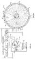
- FIGS. 4A and 4Bis a diagram illustrating an external spiral servo writer used to write a plurality of spiral reference patterns according to the processes of FIGS. 2 and 3 , according to one embodiment of the invention.
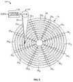
- FIG. 4Cis a simplified diagram illustrating an example of measuring radial displacement as part of a position correction value, according to one embodiment of the invention.
- FIG. 4Dis a simplified diagram illustrating an example of measuring circumferential displacement as part of a position correction value, according to one embodiment of the invention.
- FIG. 5shows a disk drive that processes the reference servo bursts in the spiral reference patterns to self-servo write servo sectors to the disk, according to one embodiment of the invention.
- FIG. 6shows an embodiment wherein an external servo writer is used to read the reference servo bursts in the spiral reference patterns in order to write the servo sectors to the disk.
- FIG. 7shows an embodiment wherein a plurality of external servo writer's process the HDAs output by an external spiral servo writer.
- spiral reference patterns 36 0 – 36 7FIG. 4B
- the spiral reference patternsmay be used as a reference for writing servo sectors, as will be discussed.
- the disk drive 18comprises control circuitry 20 and a head disk assembly (HDA) 22 .
- the HDAcomprises the disk 16 , an actuator arm 24 , a head 26 connected to a distal end of the actuator arm 24 , and a voice coil motor 28 for rotating the actuator arm 24 about a pivot to position the head 26 radially over the disk 16 .
- an external spiral servo writer 30including a head positioner 34 , timing circuitry 42 , servo decode circuit 43 , and pattern circuitry 46 may be used to aid in writing a plurality of spiral reference patterns 36 0 – 36 7 between a center track 50 of a first band of tracks 51 written near an outer diameter (OD) circumference of the disk and a center track 52 of a second band of tracks 53 written near an inner diameter (ID) circumference of the disk.
- Thermal expansion of the disk during the writing of the plurality of spiral reference patterns 36 0 – 36 7may increase a radial distance between the inner and outer center tracks 50 and 52 as well as introduce circumferential errors.
- a spindle motor(not shown) may generate heat that is conducted to the disk 16 .
- the heatcauses thermal expansion of the disk.
- This thermal expansioncan be on the order of several data tracks so that, without adjustment, a last written spiral reference pattern may have a different slope from a first written spiral reference pattern causing an abrupt discontinuity that may interfere with circular track following desired for writing servo sectors.
- Embodiments of the inventionprovide for a method and system for reducing spiral write time and clock track drift while writing the spiral servo patterns to the disk.
- the external spiral servo writer 30 having a disk drive 18 coupled theretomay perform a process to control a radial location of a head 26 of the disk drive such that a first band of tracks 51 , in this example, at the outer diameter (OD) circumference of the disk 16 are written (block 112 ). Further, a radial location of the head 26 is controlled by the external spiral servo writer 30 to write a second band of tracks 53 , in this example, at the inner diameter (ID) circumference of the disk (block 114 ).
- a substantial majority of the tracks of the band of trackseach includes typical servo information, e.g., a plurality of servo sectors each including a preamble, a track number, a sync mark, a servo wedge ID, etc.
- the external spiral servo writer 30determines a first OD first reference center position 62 for the center track 50 of the first OD band of tracks 51 (block 116 ).
- the external spiral servo writer 30determines a second ID reference center position 59 for the center track 52 of the ID band of tracks 53 (block 118 ). Both the ID reference center position and OD reference center position are based upon the external spiral servo writer's own positioning and timing circuitry, for use as a reference, utilizing for example, an optical encoder or a laser interferometer.
- a head positioning pin 33 of the external spiral servo writer 30may be inserted into the HDA 22 before writing the first OD band of tracks 51 and the second ID band of tracks 53 and before writing any spiral reference patterns 36 0 – 36 7 , as will be discussed, such that the head positioning pin engages the actuator arm 24 .
- the external spiral servo writercomprises head positioning mechanics 34 used to derive a radial location and circumferential location of the head 26 .
- the head positioning pin 33is actuated in response to the radial location of the head 26 in a closed loop system in order to position the head 26 radially over the disk 16 while writing a plurality of servo sectors to the disk in order to form the OD first band of tracks 51 and the ID second band of tracks 53 , as well as, in one embodiment, servo bursts to write a plurality of spiral reference patterns 36 0 – 36 7 .
- Each spiral reference pattern 36 imay be written from the center track 50 of the first OD band of tracks 51 to the center track 52 of the ID band of tracks 53 .
- the spiral reference patternsmay be written from the ID to the OD in similar fashion.
- the head positioning mechanics 34may include an optical encoder to derive the radial location and the circumferential location of the head upon encountering either the first OD reference center track 50 or the second ID reference track 52 .
- a laser interferometermay be utilized for this purpose.
- the external spiral servo writer 30in order to write a spiral reference pattern, first moves the head to a first predicted position 57 for the center track 52 of the ID band of tracks 53 (block 120 ). The external spiral servo writer then moves the head to the ID center track 52 and calculates a first ID position correction based upon the difference between the predicted position 57 for the center track of the ID band of tracks and the actual ID reference center position 59 (block 124 ).
- a servo decode circuit 43 of the external spiral servo writer 30collects track numbers and sync mark data from each servo sector of each track as the head is moved to the ID reference center position. As the servo wedges are read, the data in each servo sector is resolved into a track number with a fractional track value (based upon sync amplitudes). These collected tracks with fractional track values are averaged into a single track/fraction value.
- FIG. 4Cillustrates an example of measuring radial displacement as part of the position correction value.
- the first ID reference center positionis calculated based upon the previously-described track-fraction value, the track pitch with which the reference track band was written, and the current position of the external spiral servo writer 30 .
- circumferential position informationmay be gathered based on the location of the tracks of the first band of ID track sync marks versus timing information from the clock track/circumferential time reference (utilizing timing circuitry 42 ).
- FIG. 4Dis a simplified diagram illustrating an example of measuring circumferential displacement as part of the position correction value.
- Timing informationmay be gathered based on timing information gathered immediately after the first center ID reference track is written to obtain an initial offset value and this initial offset value can be subsequently updated each time the first center ID reference track is sought to.
- a sync detect 404 from the servo decode circuit 43is compared to the timing circuit once-around reference 406 .
- the previously-described processis then utilized for the OD band of tracks 51 . Again the head is moved to the predicted position 60 for the center track 50 of the OD band of tracks 51 (block 126 ) then the head is moved to the OD reference center track 50 (block 128 ). Then, a second OD position correction is calculated based upon the difference between the predicted position 60 for the center track 50 of the OD band of tracks and the actual OD reference center position 62 . The previously-described process for calculating the position correction based on radial and circumferential components is utilized. Further, at block 132 , the distance 63 is measured between the first and second reference center positions 62 and 59 .
- a spiral patternmay be written (block 136 ).
- a spiral reference pattern 36 0may be written from the OD reference center position 62 towards the center track 52 of the ID band of tracks to a predicted ID center position 70 based upon the measured distance 63 between the first and second reference center position and based upon a spiral slope correction.
- the spiral slope correctionis based upon the previously calculated first ID position correction and the second OD position correction (with both radial and circumferential correction components) and the measured distance 63 between the OD reference center position 62 and the ID reference center position 59 .
- a spiral reference pattern(e.g. 36 0 ) may be written utilizing the measured distance between the ID and OD reference center positions and based upon the spiral slope correction.
- each spiral reference patternis written (e.g. 36 0 – 36 7 )
- the distance between the ID and the OD reference center positionsare again measured
- the circumferential measurement datais compared against the initial circumferential measurement data gathered when the respective center track of the reference band of tracks was established, and the spiral slope and/or clock timing are adjusted to correct for the differences in the two measurements.
- the spiral radial position data from the predicted positionsis compared against the base line reference center positions, as previously discussed to calculate position corrections, and is also used to adjust the spiral slope and length of the next spiral to be written (e.g. 36 0 – 36 7 ).
- radial and circumferential position correctionsare applied after writing each spiral reference pattern.
- spiral reference patternsare easily calculated based upon four known inputs: the OD reference center track 50 ; the ID reference center track 52 ; a predicted OD spiral start position 60 ; and a predicted spiral ID position 57 .
- a predicted ID spiral end position 57is sought to and an ID position correction value is calculated.
- a predicted OD spiral start position 60is sought to and a spiral start position correction is calculated.
- both a new spiral length and a new spiral slope correctionare determined and a new spiral (e.g. 36 1 – 36 7 , etc.) is written from the OD reference track position towards the ID reference track position 70 (e.g.
- the previously described system and methodprovides a significantly reduced write time for spiral reference patterns, as well as, increased accuracy by accounting for both radial and circumferential position errors.
- the head positioning pin 33is removed from the HDA 22 and the head 26 internal to the disk drive 18 is used to read the reference servo bursts in the spiral reference patters 36 0 – 36 7 in order to write the servo sectors 38 0 – 38 7 to the disk 16 , as shown in FIG. 5 , thereby defining the plurality of radially spaced concentric data tracks 40 .
- control circuitry 20 of the disk drive 18may be used to read the reference servo burst in the spiral reference patterns 36 0 – 36 7 in order to write the servo bursts 38 0 – 38 7 to the disk 16 during a self-servo writing operation.
- an external servo writer 50may be used to read the reference servo bursts in the spiral reference patterns 36 0 – 36 7 in order to write the servo burst 38 0 – 38 7 to the disk 16 , as will be discussed.
- FIG. 4Ashows the entire disk drive 18 inserted into an external spiral servo writer 30 while writing the spiral reference patterns 36 0 – 36 7 to the disk 16 .
- the HDA 22may be inserted into the external spiral servo writer 30 , wherein a printed circuit board assembly (PCBA) comprising the control circuitry 20 is mounted to the HDA after the external writer 30 writes the spiral reference patterns 36 0 – 36 7 to the disk 16 .
- PCBAprinted circuit board assembly
- the head positioning pin 33may be connected to the actuator arm 24 by applying a small amount of current to the voice coil motor 28 in order to bias the actuator arm 24 against the head positioning pin 33 .
- the head positioning mechanics 34may include a laser interferometer for generating the radial location of the head 26 .
- the head positioning mechanicsmay include an optical encoder.
- any suitable device for generating the radial location of the head 26may be employed.
- the external servo writer 30comprises a clock head 41 which is also inserted into the HDA 22 for reading a clock track recorded on an outer diameter of the disk 16 .
- Timing circuitry 42 within the external servo writer 30processes the signal 44 from the clock head 41 in order to write the reference servo bursts at the appropriate circumferential location.
- Pattern circuitry 46 within the external servo writer 30generates the reference servo burst pattern applied to the head 26 at the appropriate time.
- the number of spiral reference patterns 36 0 – 36 N as well as the slope of each spiral reference pattern 36 imay be selected so that the external spiral servo writer 30 can process the disk drive 18 in a significantly shorter time period as compared to writing a complete set of servo sectors 38 0 – 38 7 to the disk 16 .
- Thisincreases the throughput of the external spiral servo writer 30 by having the disk drives self-servo write the servo sectors 38 0 – 38 7 using the spiral reference patterns 36 0 – 36 7 while avoiding errors inherent in having the disk drive write the spiral reference patterns 36 0 – 36 7 .
- the servo sectors 38 0 – 38 Nare written along a substantially circular path while tracking the spiral reference patterns 36 0 – 36 N .
- the servo sectors 38 0 – 38 7form a plurality of servo wedges, which extend from servo sector to servo sector.
- the control circuitry 20 of FIG. 5computes a position error for the head 26 with respect to a circular trajectory in response to the reference servo bursts.
- a conventional servo algorithmmay be employed to compute the head position error (e.g., an algorithm similar to that used to compute the head position error from the servo sectors 38 0 – 38 N during normal operation of the disk drive).
- the head position erroris input to a servo control system, which generates the appropriate control signal applied to the voice coil motor 28 .
- the algorithm for computing the head position erroris continuously updated relative to the circumferential location of the head 26 to account for the spiral trajectory of the reference servo bursts in the spiral reference patterns 36 0 – 36 N .
- a timing clockis generated in response to the reference servo bursts, wherein the timing clock is used to write the servo sectors 38 0 – 38 N at the appropriate circumferential location on the disk 16 .
- the external spiral servo writer 30writes a periodic clock signal together with the spiral reference patterns 36 0 – 36 N , wherein the periodic clock signal is processed in order to generate the timing clock used to write the servo sectors 38 0 – 38 N at the appropriate circumferential location on the disk 16 .
- FIG. 6shows an embodiment of the present invention wherein after writing the spiral reference patterns 36 0 – 36 N to the disk 16 , ( FIGS. 4A–4B ), the HDA 22 is inserted into an external servo writer 50 comprising suitable circuitry for reading and processing the spiral reference patterns 36 0 – 36 N in order to write the servo bursts 38 0 – 38 N to the disk 16 .
- the external servo writer 50comprises a read/write channel 52 for interfacing with a preamp 54 in the HDA 22 .
- the preamp 54amplifies a read signal emanating from the head 26 over line 56 to generate an amplified read signal applied to the read/write channel 52 over line 58 .
- the read/write channel 52comprises suitable circuitry/software for measuring the reference servo bursts (e.g., integration circuitry/software) and for transmitting a signal representing the reference servo bursts to a servo controller 60 over line 64 .
- the servo controller 60processes the reference servo burst signals to generate a head position error.
- the head position erroris used to generate a VCM control signal applied to the VCM 28 over line 66 in order to maintain the head 26 along a circular trajectory.
- the servo controller 60also generates a spindle motor control signal applied to a spindle motor 68 over line 70 to maintain the disk 16 at a desired angular velocity.
- Control circuitry 72processes information received from the read/write channel 52 over line 74 associated with the reference servo bursts (e.g., timing information) and provides the servo burst patterns to the read/write channel 52 at the appropriate time.
- the servo bursts patternsare provided to the preamp 54 , which modulates a current in the head 26 in order to write the servo to the disk 16 .
- the control circuitry 72also transmits control information over line 76 to the servo controller 60 , such as the target servo track to be written.
- control informationsuch as the target servo track to be written.
- the HDA 22is removed from the external servo writer 50 and a printed circuit board assembly (PCBA) comprising the control circuitry 20 ( FIG. 3A ) is mounted to the HDA 22 .
- PCBAprinted circuit board assembly
- the external servo writer 50 of FIG. 7interfaces with the HDA 22 over the same connections as the control circuitry 20 to minimize the modifications needed to facilitate the external servo writer 50 .
- the external servo writer 50is less expensive than a conventional servo writer because it does not require a clean room or sophisticated head positioning mechanics.
- a plurality of external servo writers 50 0 – 50 Nprocess the HDAs 22 i ⁇ i+N output by an external spiral servo writer 30 in order to write the servo sectors less expensively and more efficiently than a conventional servo writer.
Landscapes
- Moving Of The Head To Find And Align With The Track (AREA)
Abstract
Description
C+0.5=25.5, (C−5)+0.8=20.8;
X=N+P(25.5−20.8)
Claims (30)
Priority Applications (1)
| Application Number | Priority Date | Filing Date | Title |
|---|---|---|---|
| US11/196,076US7145744B1 (en) | 2005-08-03 | 2005-08-03 | Reducing spiral write time and clock track drift while writing spiral reference patterns to a disk of a disk drive |
Applications Claiming Priority (1)
| Application Number | Priority Date | Filing Date | Title |
|---|---|---|---|
| US11/196,076US7145744B1 (en) | 2005-08-03 | 2005-08-03 | Reducing spiral write time and clock track drift while writing spiral reference patterns to a disk of a disk drive |
Publications (1)
| Publication Number | Publication Date |
|---|---|
| US7145744B1true US7145744B1 (en) | 2006-12-05 |
Family
ID=37480655
Family Applications (1)
| Application Number | Title | Priority Date | Filing Date |
|---|---|---|---|
| US11/196,076Expired - Fee RelatedUS7145744B1 (en) | 2005-08-03 | 2005-08-03 | Reducing spiral write time and clock track drift while writing spiral reference patterns to a disk of a disk drive |
Country Status (1)
| Country | Link |
|---|---|
| US (1) | US7145744B1 (en) |
Cited By (57)
| Publication number | Priority date | Publication date | Assignee | Title |
|---|---|---|---|---|
| US20060103967A1 (en)* | 2004-11-18 | 2006-05-18 | Samsung Electronics Co., Ltd. | Method for writing spiral reference servo signal in hard disk drive and method for compensating for temperature |
| US20070081268A1 (en)* | 2005-10-11 | 2007-04-12 | Samsung Electronics Co., Ltd. | Method of writing a reference servo signal of hard disk drive and apparatus suitable therefor |
| US20080013202A1 (en)* | 2006-05-19 | 2008-01-17 | Maxtor Corporation | Self-servo writing using staged patterning |
| US20080030889A1 (en)* | 2006-05-19 | 2008-02-07 | Maxtor Corporation | Self-servo writing using radially overlapped servo segments |
| US20080030894A1 (en)* | 2006-04-26 | 2008-02-07 | Maxtor Corporation | Servo writing with offset compensation for prewritten reference |
| US7375918B1 (en)* | 2002-04-23 | 2008-05-20 | Maxtor Corporation | Method of self-servo writing in a disk drive using multiple timing windows |
| US7499234B1 (en)* | 2003-06-02 | 2009-03-03 | Maxtor Corporation | Method and apparatus for modifying spiral profile using reference tracks written onto a disk surface of a disk drive |
| US7502195B1 (en) | 2007-02-09 | 2009-03-10 | Western Digital Technologies, Inc. | Compensating for thermal expansion when writing spiral tracks to a disk of a disk drive |
| US7505223B1 (en) | 2007-09-05 | 2009-03-17 | Western Digital Technologies, Inc. | Compensating for non-linear thermal expansion when writing spiral tracks to a disk of a disk drive |
| US7656604B1 (en) | 2007-12-10 | 2010-02-02 | Western Digital Technologies, Inc. | Disk drive demodulating a spiral track by finding a maximum correlation between a spiral track crossing signal and a time-shifted nominal spiral track crossing signal |
| US20100123972A1 (en)* | 2008-11-18 | 2010-05-20 | Fujitsu Limited | Information storage apparatus, servo pattern formation control apparatus, and recording medium |
| US7746592B1 (en) | 2009-02-13 | 2010-06-29 | Western Digital Technologies, Inc. | Disk drive detecting defective spiral servo track |
| US20100177432A1 (en)* | 2009-01-15 | 2010-07-15 | Toshiba Storage Device Corporation | Information storage apparatus, method for correcting feed pitch of read/write head, and method for forming servo pattern |
| US20100177431A1 (en)* | 2009-01-15 | 2010-07-15 | Toshiba Storage Device Corporation | Information storage apparatus, adjustment apparatus thereof, and method for forming servo pattern |
| US7839591B1 (en) | 2008-02-11 | 2010-11-23 | Western Digital Technologies, Inc. | Disk drive comprising index spiral track identified by change in sync mark |
| US7852592B1 (en) | 2008-01-29 | 2010-12-14 | Western Digital Technologies, Inc. | Spiral slope approximation of spiral patterns written to a disk of a disk drive |
| US7864481B1 (en) | 2009-01-26 | 2011-01-04 | Western Digital Technologies, Inc. | Evaluating distribution of peak signals representing reference track crossings to compensate for thermal expansion when writing spiral tracks to a disk |
| US7936530B1 (en)* | 2007-08-20 | 2011-05-03 | Marvell International Ltd. | Method to write ramp-track |
| US7940487B1 (en) | 2008-06-24 | 2011-05-10 | Western Digital Technologies, Inc. | Heating a head disk assembly for a time interval prior to writing spiral servo tracks to the disk |
| US7995305B1 (en) | 2007-08-20 | 2011-08-09 | Marvell International Ltd. | Calibrating voice coil motors |
| US20120127605A1 (en)* | 2010-11-18 | 2012-05-24 | Xyratex Technology Limited | Method and device for mapping the magnetic field or magnetic field sensitivity of a recording head |
| US8358145B1 (en) | 2009-06-19 | 2013-01-22 | Western Digital Technologies, Inc. | Self-heating integrated circuit |
| US8432629B1 (en) | 2011-05-23 | 2013-04-30 | Western Digital Technologies, Inc. | Disk drive centering sync frames on sync marks of a spiral track |
| US8451697B1 (en) | 2011-05-23 | 2013-05-28 | Western Digital Technologies, Inc. | Disk drive centering demodulation windows on spiral tracks during a seek operation |
| US20130250452A1 (en)* | 2012-03-22 | 2013-09-26 | Kabushiki Kaisha Toshiba | Disk storage apparatus and method of writing servo patterns |
| US8634154B1 (en) | 2011-08-08 | 2014-01-21 | Western Digital Technologies, Inc. | Disk drive writing a sync mark seam in a bootstrap spiral track |
| US8634283B1 (en) | 2011-08-08 | 2014-01-21 | Western Digital Technologies, Inc. | Disk drive performing in-drive spiral track writing |
| US8665551B1 (en) | 2011-12-22 | 2014-03-04 | Western Digital Technologies, Inc. | Disk drive adjusting gain and offset of BEMF velocity sensor during self writing of spiral tracks |
| US8879194B2 (en)* | 2013-02-13 | 2014-11-04 | Kabushiki Kaisha Toshiba | Calibration of ramp location in a disk drive employing spiral-based self servo writing |
| US8896957B1 (en) | 2013-05-10 | 2014-11-25 | Western Digital Technologies, Inc. | Disk drive performing spiral scan of disk surface to detect residual data |
| US8902535B1 (en) | 2012-12-12 | 2014-12-02 | Western Digital Technologies, Inc. | Disk drive adapting feed-forward compensation using iterative learning control over segments of seek length |
| US8917474B1 (en) | 2011-08-08 | 2014-12-23 | Western Digital Technologies, Inc. | Disk drive calibrating a velocity profile prior to writing a spiral track |
| US8941939B1 (en) | 2013-10-24 | 2015-01-27 | Western Digital Technologies, Inc. | Disk drive using VCM BEMF feed-forward compensation to write servo data to a disk |
| US8964179B2 (en) | 2013-02-21 | 2015-02-24 | Western Digital Technologies, Inc. | Method and apparatus for measuring a pitch static attitude of a head stack assembly |
| US8982490B1 (en) | 2014-04-24 | 2015-03-17 | Western Digital Technologies, Inc. | Data storage device reading first spiral track while simultaneously writing second spiral track |
| US9022444B1 (en) | 2013-05-20 | 2015-05-05 | Western Digital Technologies, Inc. | Vacuum nozzle having back-pressure release hole |
| US9053727B1 (en) | 2014-06-02 | 2015-06-09 | Western Digital Technologies, Inc. | Disk drive opening spiral crossing window based on DC and AC spiral track error |
| US9076490B1 (en) | 2012-12-12 | 2015-07-07 | Western Digital Technologies, Inc. | Disk drive writing radial offset spiral servo tracks by reading spiral seed tracks |
| US9120232B1 (en) | 2013-07-26 | 2015-09-01 | Western Digital Technologies, Inc. | Vacuum pick-up end effector with improved vacuum reading for small surface |
| US9150360B1 (en) | 2013-05-16 | 2015-10-06 | Western Digital Technologies, Inc. | Mechanism to deliver fastener vertically |
| US9157817B1 (en) | 2014-06-09 | 2015-10-13 | Western Digital Technologies, Inc. | HSA swage metrology calibration using solid weight gauge and torque sensor |
| US9180563B2 (en) | 2013-03-08 | 2015-11-10 | Western Digital Technologies, Inc. | De-swage machine for removal of a head from a head stack assembly and method of using the same |
| US9208810B1 (en) | 2014-04-24 | 2015-12-08 | Western Digital Technologies, Inc. | Data storage device attenuating interference from first spiral track when reading second spiral track |
| US9230579B1 (en) | 2012-09-21 | 2016-01-05 | Western Digital Technologies, Inc. | Comb gripper for use with a shipping comb and a ramp in the assembly of a disk drive |
| US9236071B1 (en) | 2014-12-21 | 2016-01-12 | Western Digital Technologies, Inc. | Etching continuous periodic pattern on a suspension to adjust pitch and roll static attitude |
| US9245560B1 (en) | 2015-03-09 | 2016-01-26 | Western Digital Technologies, Inc. | Data storage device measuring reader/writer offset by reading spiral track and concentric servo sectors |
| US9275677B1 (en) | 2010-09-30 | 2016-03-01 | Western Digital Technologies, Inc. | Hard disk drive top cover removal |
| US9286922B1 (en) | 2015-06-26 | 2016-03-15 | Western Digital Technologies, Inc. | Adaptive tacking of head gimbal assembly long tail and HSA arm slot |
| US9299372B1 (en) | 2015-04-29 | 2016-03-29 | Western Digital Technologies, Inc. | Swage key enabling simultaneous transfer of two head gimbal assemblies onto two corresponding actuator pivot flex assembly arms |
| US9404939B1 (en) | 2014-06-24 | 2016-08-02 | Western Digital (Fremont), Llc | Pre-amplifier cartridge for test equipment of head gimbal assembly |
| US9737979B1 (en) | 2014-02-13 | 2017-08-22 | Western Digital Technologies, Inc. | Vacuum embedded bit for screw drivers |
| US9799377B1 (en) | 2015-05-01 | 2017-10-24 | Western Digital Technologies, Inc. | Gas-charging head with integral valves |
| US9895725B1 (en) | 2014-10-07 | 2018-02-20 | Western Digital Technologies, Inc. | Disk clamp and motor hub cleaning with stamping adhesive |
| US9947356B1 (en)* | 2017-03-09 | 2018-04-17 | Kabushiki Kaisha Toshiba | Calibration spiral to improve guide spiral placement |
| US9996071B2 (en) | 2014-06-24 | 2018-06-12 | Western Digital Technologies, Inc. | Moveable slider for use in a device assembly process |
| US10039219B1 (en) | 2015-09-28 | 2018-07-31 | Western Digital Technologies, Inc. | Method and devices for picking and placing workpieces into devices under manufacture using dual robots |
| CN114721603A (en)* | 2022-06-10 | 2022-07-08 | 浙江豪联信息科技有限公司 | Electric data processing and identifying method for avoiding disk drift |
Citations (3)
| Publication number | Priority date | Publication date | Assignee | Title |
|---|---|---|---|---|
| US5668679A (en) | 1995-12-21 | 1997-09-16 | Quantum Corporation | System for self-servowriting a disk drive |
| US6992848B1 (en)* | 2002-03-29 | 2006-01-31 | Western Digital Technologies, Inc. | Using an external spiral servo writer to write spiral reference patterns to a disk to facilitate writing product servo bursts to the disk |
| US7088533B1 (en)* | 2002-04-23 | 2006-08-08 | Maxtor Corporation | Method of self-servo writing in a disk drive using a spiral pattern |
- 2005
- 2005-08-03USUS11/196,076patent/US7145744B1/ennot_activeExpired - Fee Related
Patent Citations (3)
| Publication number | Priority date | Publication date | Assignee | Title |
|---|---|---|---|---|
| US5668679A (en) | 1995-12-21 | 1997-09-16 | Quantum Corporation | System for self-servowriting a disk drive |
| US6992848B1 (en)* | 2002-03-29 | 2006-01-31 | Western Digital Technologies, Inc. | Using an external spiral servo writer to write spiral reference patterns to a disk to facilitate writing product servo bursts to the disk |
| US7088533B1 (en)* | 2002-04-23 | 2006-08-08 | Maxtor Corporation | Method of self-servo writing in a disk drive using a spiral pattern |
Cited By (68)
| Publication number | Priority date | Publication date | Assignee | Title |
|---|---|---|---|---|
| US7375918B1 (en)* | 2002-04-23 | 2008-05-20 | Maxtor Corporation | Method of self-servo writing in a disk drive using multiple timing windows |
| US7499234B1 (en)* | 2003-06-02 | 2009-03-03 | Maxtor Corporation | Method and apparatus for modifying spiral profile using reference tracks written onto a disk surface of a disk drive |
| US7321479B2 (en)* | 2004-11-18 | 2008-01-22 | Samsung Electronics Co., Ltd. | Method for writing spiral reference servo signal in hard disk drive and method for compensating for temperature |
| US20060103967A1 (en)* | 2004-11-18 | 2006-05-18 | Samsung Electronics Co., Ltd. | Method for writing spiral reference servo signal in hard disk drive and method for compensating for temperature |
| US7333286B2 (en)* | 2005-10-11 | 2008-02-19 | Samsung Electronics Co., Ltd. | Method of writing a reference servo signal of hard disk drive and apparatus suitable therefor |
| US20070081268A1 (en)* | 2005-10-11 | 2007-04-12 | Samsung Electronics Co., Ltd. | Method of writing a reference servo signal of hard disk drive and apparatus suitable therefor |
| US20080030894A1 (en)* | 2006-04-26 | 2008-02-07 | Maxtor Corporation | Servo writing with offset compensation for prewritten reference |
| US7551387B2 (en) | 2006-04-26 | 2009-06-23 | Maxtor Corporation | Servo writing with offset compensation for prewritten reference |
| US7619846B2 (en) | 2006-05-19 | 2009-11-17 | Maxtor Corporation | Self-servo writing using staged patterning |
| US20080030889A1 (en)* | 2006-05-19 | 2008-02-07 | Maxtor Corporation | Self-servo writing using radially overlapped servo segments |
| US20080013202A1 (en)* | 2006-05-19 | 2008-01-17 | Maxtor Corporation | Self-servo writing using staged patterning |
| US7414809B2 (en) | 2006-05-19 | 2008-08-19 | Maxtor Corporation | Servo writing using radially overlapped servo segments |
| US7502195B1 (en) | 2007-02-09 | 2009-03-10 | Western Digital Technologies, Inc. | Compensating for thermal expansion when writing spiral tracks to a disk of a disk drive |
| US7995305B1 (en) | 2007-08-20 | 2011-08-09 | Marvell International Ltd. | Calibrating voice coil motors |
| US8493684B1 (en) | 2007-08-20 | 2013-07-23 | Marvell International Ltd. | Calibrating voice coil motors |
| US7936530B1 (en)* | 2007-08-20 | 2011-05-03 | Marvell International Ltd. | Method to write ramp-track |
| US7505223B1 (en) | 2007-09-05 | 2009-03-17 | Western Digital Technologies, Inc. | Compensating for non-linear thermal expansion when writing spiral tracks to a disk of a disk drive |
| US7656604B1 (en) | 2007-12-10 | 2010-02-02 | Western Digital Technologies, Inc. | Disk drive demodulating a spiral track by finding a maximum correlation between a spiral track crossing signal and a time-shifted nominal spiral track crossing signal |
| US7852592B1 (en) | 2008-01-29 | 2010-12-14 | Western Digital Technologies, Inc. | Spiral slope approximation of spiral patterns written to a disk of a disk drive |
| US7839591B1 (en) | 2008-02-11 | 2010-11-23 | Western Digital Technologies, Inc. | Disk drive comprising index spiral track identified by change in sync mark |
| US7940487B1 (en) | 2008-06-24 | 2011-05-10 | Western Digital Technologies, Inc. | Heating a head disk assembly for a time interval prior to writing spiral servo tracks to the disk |
| US8446686B2 (en) | 2008-11-18 | 2013-05-21 | Kabushiki Kaisha Toshiba | Information storage apparatus, servo pattern formation control apparatus, and recording medium |
| US20100123972A1 (en)* | 2008-11-18 | 2010-05-20 | Fujitsu Limited | Information storage apparatus, servo pattern formation control apparatus, and recording medium |
| US20100177432A1 (en)* | 2009-01-15 | 2010-07-15 | Toshiba Storage Device Corporation | Information storage apparatus, method for correcting feed pitch of read/write head, and method for forming servo pattern |
| US8199423B2 (en) | 2009-01-15 | 2012-06-12 | Kabushiki Kaisha Toshiba | Information storage apparatus, method for correcting feed pitch of read/write head, and method for forming servo pattern |
| US20100177431A1 (en)* | 2009-01-15 | 2010-07-15 | Toshiba Storage Device Corporation | Information storage apparatus, adjustment apparatus thereof, and method for forming servo pattern |
| US7864481B1 (en) | 2009-01-26 | 2011-01-04 | Western Digital Technologies, Inc. | Evaluating distribution of peak signals representing reference track crossings to compensate for thermal expansion when writing spiral tracks to a disk |
| US7746592B1 (en) | 2009-02-13 | 2010-06-29 | Western Digital Technologies, Inc. | Disk drive detecting defective spiral servo track |
| US8358145B1 (en) | 2009-06-19 | 2013-01-22 | Western Digital Technologies, Inc. | Self-heating integrated circuit |
| US9275927B1 (en) | 2009-06-19 | 2016-03-01 | Western Digital Technologies, Inc. | Self-heating integrated circuit |
| US9275677B1 (en) | 2010-09-30 | 2016-03-01 | Western Digital Technologies, Inc. | Hard disk drive top cover removal |
| US20120127605A1 (en)* | 2010-11-18 | 2012-05-24 | Xyratex Technology Limited | Method and device for mapping the magnetic field or magnetic field sensitivity of a recording head |
| US8432629B1 (en) | 2011-05-23 | 2013-04-30 | Western Digital Technologies, Inc. | Disk drive centering sync frames on sync marks of a spiral track |
| US8451697B1 (en) | 2011-05-23 | 2013-05-28 | Western Digital Technologies, Inc. | Disk drive centering demodulation windows on spiral tracks during a seek operation |
| US8634283B1 (en) | 2011-08-08 | 2014-01-21 | Western Digital Technologies, Inc. | Disk drive performing in-drive spiral track writing |
| US8634154B1 (en) | 2011-08-08 | 2014-01-21 | Western Digital Technologies, Inc. | Disk drive writing a sync mark seam in a bootstrap spiral track |
| US8917474B1 (en) | 2011-08-08 | 2014-12-23 | Western Digital Technologies, Inc. | Disk drive calibrating a velocity profile prior to writing a spiral track |
| US8665551B1 (en) | 2011-12-22 | 2014-03-04 | Western Digital Technologies, Inc. | Disk drive adjusting gain and offset of BEMF velocity sensor during self writing of spiral tracks |
| US20130250452A1 (en)* | 2012-03-22 | 2013-09-26 | Kabushiki Kaisha Toshiba | Disk storage apparatus and method of writing servo patterns |
| US9230579B1 (en) | 2012-09-21 | 2016-01-05 | Western Digital Technologies, Inc. | Comb gripper for use with a shipping comb and a ramp in the assembly of a disk drive |
| US8902535B1 (en) | 2012-12-12 | 2014-12-02 | Western Digital Technologies, Inc. | Disk drive adapting feed-forward compensation using iterative learning control over segments of seek length |
| US9076490B1 (en) | 2012-12-12 | 2015-07-07 | Western Digital Technologies, Inc. | Disk drive writing radial offset spiral servo tracks by reading spiral seed tracks |
| US8879194B2 (en)* | 2013-02-13 | 2014-11-04 | Kabushiki Kaisha Toshiba | Calibration of ramp location in a disk drive employing spiral-based self servo writing |
| US8964179B2 (en) | 2013-02-21 | 2015-02-24 | Western Digital Technologies, Inc. | Method and apparatus for measuring a pitch static attitude of a head stack assembly |
| US9308609B2 (en) | 2013-03-08 | 2016-04-12 | Western Digital Technologies, Inc. | De-swage machine for removal of a head from a head stack assembly and method of using the same |
| US9180563B2 (en) | 2013-03-08 | 2015-11-10 | Western Digital Technologies, Inc. | De-swage machine for removal of a head from a head stack assembly and method of using the same |
| US8896957B1 (en) | 2013-05-10 | 2014-11-25 | Western Digital Technologies, Inc. | Disk drive performing spiral scan of disk surface to detect residual data |
| US9150360B1 (en) | 2013-05-16 | 2015-10-06 | Western Digital Technologies, Inc. | Mechanism to deliver fastener vertically |
| US9022444B1 (en) | 2013-05-20 | 2015-05-05 | Western Digital Technologies, Inc. | Vacuum nozzle having back-pressure release hole |
| US9120232B1 (en) | 2013-07-26 | 2015-09-01 | Western Digital Technologies, Inc. | Vacuum pick-up end effector with improved vacuum reading for small surface |
| US8941939B1 (en) | 2013-10-24 | 2015-01-27 | Western Digital Technologies, Inc. | Disk drive using VCM BEMF feed-forward compensation to write servo data to a disk |
| US9737979B1 (en) | 2014-02-13 | 2017-08-22 | Western Digital Technologies, Inc. | Vacuum embedded bit for screw drivers |
| US9208810B1 (en) | 2014-04-24 | 2015-12-08 | Western Digital Technologies, Inc. | Data storage device attenuating interference from first spiral track when reading second spiral track |
| US8982490B1 (en) | 2014-04-24 | 2015-03-17 | Western Digital Technologies, Inc. | Data storage device reading first spiral track while simultaneously writing second spiral track |
| US9053727B1 (en) | 2014-06-02 | 2015-06-09 | Western Digital Technologies, Inc. | Disk drive opening spiral crossing window based on DC and AC spiral track error |
| US9157817B1 (en) | 2014-06-09 | 2015-10-13 | Western Digital Technologies, Inc. | HSA swage metrology calibration using solid weight gauge and torque sensor |
| US9996071B2 (en) | 2014-06-24 | 2018-06-12 | Western Digital Technologies, Inc. | Moveable slider for use in a device assembly process |
| US9404939B1 (en) | 2014-06-24 | 2016-08-02 | Western Digital (Fremont), Llc | Pre-amplifier cartridge for test equipment of head gimbal assembly |
| US9895725B1 (en) | 2014-10-07 | 2018-02-20 | Western Digital Technologies, Inc. | Disk clamp and motor hub cleaning with stamping adhesive |
| US9236071B1 (en) | 2014-12-21 | 2016-01-12 | Western Digital Technologies, Inc. | Etching continuous periodic pattern on a suspension to adjust pitch and roll static attitude |
| US9245560B1 (en) | 2015-03-09 | 2016-01-26 | Western Digital Technologies, Inc. | Data storage device measuring reader/writer offset by reading spiral track and concentric servo sectors |
| US9299372B1 (en) | 2015-04-29 | 2016-03-29 | Western Digital Technologies, Inc. | Swage key enabling simultaneous transfer of two head gimbal assemblies onto two corresponding actuator pivot flex assembly arms |
| US9799377B1 (en) | 2015-05-01 | 2017-10-24 | Western Digital Technologies, Inc. | Gas-charging head with integral valves |
| US9286922B1 (en) | 2015-06-26 | 2016-03-15 | Western Digital Technologies, Inc. | Adaptive tacking of head gimbal assembly long tail and HSA arm slot |
| US10039219B1 (en) | 2015-09-28 | 2018-07-31 | Western Digital Technologies, Inc. | Method and devices for picking and placing workpieces into devices under manufacture using dual robots |
| US9947356B1 (en)* | 2017-03-09 | 2018-04-17 | Kabushiki Kaisha Toshiba | Calibration spiral to improve guide spiral placement |
| CN114721603A (en)* | 2022-06-10 | 2022-07-08 | 浙江豪联信息科技有限公司 | Electric data processing and identifying method for avoiding disk drift |
| CN114721603B (en)* | 2022-06-10 | 2022-08-26 | 浙江豪联信息科技有限公司 | Electric data processing and identifying method for avoiding disk drift |
Similar Documents
| Publication | Publication Date | Title |
|---|---|---|
| US7145744B1 (en) | Reducing spiral write time and clock track drift while writing spiral reference patterns to a disk of a disk drive | |
| US6992852B1 (en) | Method for reducing disk thermal expansion effects while writing reference spiral servo patterns to a disk of a disk drive | |
| US6992851B1 (en) | Method for nonsequentially writing reference spiral servo patterns to a disk to compensate for disk expansion | |
| US6992848B1 (en) | Using an external spiral servo writer to write spiral reference patterns to a disk to facilitate writing product servo bursts to the disk | |
| US8059360B1 (en) | Disk drive compensating for radial phase change of repeatable position error due to servo writing from spiral tracks | |
| US7113362B1 (en) | Servo writing a disk drive by processing spiral tracks in an interleaved manner | |
| US8780473B1 (en) | Disk drive selecting a global digital-to-analog setting for a plurality of heads | |
| US6989954B1 (en) | Demodulating servo sectors and spiral tracks using common circuitry | |
| US8743495B1 (en) | Disk drive detecting track squeeze when circular tracks are defined from non-circular servo tracks | |
| US7502195B1 (en) | Compensating for thermal expansion when writing spiral tracks to a disk of a disk drive | |
| US7505223B1 (en) | Compensating for non-linear thermal expansion when writing spiral tracks to a disk of a disk drive | |
| US7602575B1 (en) | Disk drive adjusting estimated reader/writer offset to achieve target burst crossing signal amplitude when propagating servo sectors | |
| US6469859B1 (en) | Method and system for accurate self-servowriting with normalization in a disk drive | |
| US7872829B2 (en) | Method and apparatus for offset control in a disk drive | |
| US5940240A (en) | Constant velocity servo linearity calibration method for MR head | |
| US6771443B2 (en) | Circumferential positioning of servo sectors for servo track writing | |
| US20080002280A1 (en) | Method and apparatus for head positioning control in a disk drive | |
| US7633705B2 (en) | Method and apparatus for determining disk-runout information in a disk drive | |
| JP2523922B2 (en) | Track following control device | |
| US7006322B2 (en) | Method and apparatus for performing self-servo writing in a disk drive | |
| US8094404B1 (en) | Propagation self servo write system and method for storage devices employing sector-servo scheme | |
| US6970320B2 (en) | Servo pattern recording method | |
| GB2280302A (en) | A servo-writer for a disk drive using a clock disk | |
| JP3705752B2 (en) | Method and data storage system for writing servo track on disk medium | |
| JP2008146724A (en) | Disk storage device and servo test method |
Legal Events
| Date | Code | Title | Description |
|---|---|---|---|
| AS | Assignment | Owner name:WESTERN DIGITAL TECHNOLOGIES, INC., CALIFORNIA Free format text:ASSIGNMENT OF ASSIGNORS INTEREST;ASSIGNORS:CLAWSON, WILLIAM W.;HUGUNIN, TOMAS D.;REEL/FRAME:016838/0926 Effective date:20050721 | |
| REMI | Maintenance fee reminder mailed | ||
| FPAY | Fee payment | Year of fee payment:4 | |
| SULP | Surcharge for late payment | ||
| FPAY | Fee payment | Year of fee payment:8 | |
| SULP | Surcharge for late payment | Year of fee payment:7 | |
| AS | Assignment | Owner name:U.S. BANK NATIONAL ASSOCIATION, AS COLLATERAL AGENT, CALIFORNIA Free format text:SECURITY AGREEMENT;ASSIGNOR:WESTERN DIGITAL TECHNOLOGIES, INC.;REEL/FRAME:038744/0281 Effective date:20160512 Owner name:JPMORGAN CHASE BANK, N.A., AS COLLATERAL AGENT, ILLINOIS Free format text:SECURITY AGREEMENT;ASSIGNOR:WESTERN DIGITAL TECHNOLOGIES, INC.;REEL/FRAME:038722/0229 Effective date:20160512 Owner name:JPMORGAN CHASE BANK, N.A., AS COLLATERAL AGENT, ILLINOIS Free format text:SECURITY AGREEMENT;ASSIGNOR:WESTERN DIGITAL TECHNOLOGIES, INC.;REEL/FRAME:038744/0481 Effective date:20160512 Owner name:JPMORGAN CHASE BANK, N.A., AS COLLATERAL AGENT, IL Free format text:SECURITY AGREEMENT;ASSIGNOR:WESTERN DIGITAL TECHNOLOGIES, INC.;REEL/FRAME:038722/0229 Effective date:20160512 Owner name:JPMORGAN CHASE BANK, N.A., AS COLLATERAL AGENT, IL Free format text:SECURITY AGREEMENT;ASSIGNOR:WESTERN DIGITAL TECHNOLOGIES, INC.;REEL/FRAME:038744/0481 Effective date:20160512 Owner name:U.S. BANK NATIONAL ASSOCIATION, AS COLLATERAL AGEN Free format text:SECURITY AGREEMENT;ASSIGNOR:WESTERN DIGITAL TECHNOLOGIES, INC.;REEL/FRAME:038744/0281 Effective date:20160512 | |
| AS | Assignment | Owner name:WESTERN DIGITAL TECHNOLOGIES, INC., CALIFORNIA Free format text:RELEASE BY SECURED PARTY;ASSIGNOR:U.S. BANK NATIONAL ASSOCIATION, AS COLLATERAL AGENT;REEL/FRAME:045501/0714 Effective date:20180227 | |
| FEPP | Fee payment procedure | Free format text:MAINTENANCE FEE REMINDER MAILED (ORIGINAL EVENT CODE: REM.) | |
| LAPS | Lapse for failure to pay maintenance fees | Free format text:PATENT EXPIRED FOR FAILURE TO PAY MAINTENANCE FEES (ORIGINAL EVENT CODE: EXP.); ENTITY STATUS OF PATENT OWNER: LARGE ENTITY | |
| STCH | Information on status: patent discontinuation | Free format text:PATENT EXPIRED DUE TO NONPAYMENT OF MAINTENANCE FEES UNDER 37 CFR 1.362 | |
| FP | Lapsed due to failure to pay maintenance fee | Effective date:20181205 | |
| AS | Assignment | Owner name:WESTERN DIGITAL TECHNOLOGIES, INC., CALIFORNIA Free format text:RELEASE OF SECURITY INTEREST AT REEL 038744 FRAME 0481;ASSIGNOR:JPMORGAN CHASE BANK, N.A.;REEL/FRAME:058982/0556 Effective date:20220203 |