US7144399B2 - Instrumentation guide for orthopedic surgery - Google Patents
Instrumentation guide for orthopedic surgeryDownload PDFInfo
- Publication number
- US7144399B2 US7144399B2US10/280,838US28083802AUS7144399B2US 7144399 B2US7144399 B2US 7144399B2US 28083802 AUS28083802 AUS 28083802AUS 7144399 B2US7144399 B2US 7144399B2
- Authority
- US
- United States
- Prior art keywords
- attachment member
- transfer member
- attachment
- transfer
- guide
- Prior art date
- Legal status (The legal status is an assumption and is not a legal conclusion. Google has not performed a legal analysis and makes no representation as to the accuracy of the status listed.)
- Expired - Fee Related, expires
Links
- 230000000399orthopedic effectEffects0.000titleclaimsabstractdescription42
- 238000001356surgical procedureMethods0.000titleabstractdescription4
- 230000007246mechanismEffects0.000claimsabstractdescription20
- 230000000295complement effectEffects0.000claims1
- 238000003780insertionMethods0.000abstractdescription9
- 230000037431insertionEffects0.000abstractdescription9
- 239000007769metal materialSubstances0.000abstractdescription4
- 210000000988bone and boneAnatomy0.000description4
- 229910001220stainless steelInorganic materials0.000description4
- 239000010935stainless steelSubstances0.000description4
- 239000000463materialSubstances0.000description3
- 238000000034methodMethods0.000description3
- 239000004696Poly ether ether ketoneSubstances0.000description2
- 230000002401inhibitory effectEffects0.000description2
- 238000009434installationMethods0.000description2
- 229920002530polyetherether ketonePolymers0.000description2
- 239000012780transparent materialSubstances0.000description2
- 210000000689upper legAnatomy0.000description2
- 235000001674Agaricus brunnescensNutrition0.000description1
- 229920000049Carbon (fiber)Polymers0.000description1
- 230000009471actionEffects0.000description1
- 230000006978adaptationEffects0.000description1
- 230000008901benefitEffects0.000description1
- 239000004917carbon fiberSubstances0.000description1
- 238000004140cleaningMethods0.000description1
- 239000002131composite materialSubstances0.000description1
- 238000010276constructionMethods0.000description1
- 238000005553drillingMethods0.000description1
- 239000002184metalSubstances0.000description1
- 230000008685targetingEffects0.000description1
Images


Classifications
- A—HUMAN NECESSITIES
- A61—MEDICAL OR VETERINARY SCIENCE; HYGIENE
- A61B—DIAGNOSIS; SURGERY; IDENTIFICATION
- A61B17/00—Surgical instruments, devices or methods
- A61B17/16—Instruments for performing osteoclasis; Drills or chisels for bones; Trepans
- A61B17/17—Guides or aligning means for drills, mills, pins or wires
- A61B17/1725—Guides or aligning means for drills, mills, pins or wires for applying transverse screws or pins through intramedullary nails or pins
- A—HUMAN NECESSITIES
- A61—MEDICAL OR VETERINARY SCIENCE; HYGIENE
- A61B—DIAGNOSIS; SURGERY; IDENTIFICATION
- A61B17/00—Surgical instruments, devices or methods
- A61B17/56—Surgical instruments or methods for treatment of bones or joints; Devices specially adapted therefor
- A61B17/58—Surgical instruments or methods for treatment of bones or joints; Devices specially adapted therefor for osteosynthesis, e.g. bone plates, screws or setting implements
- A61B17/88—Osteosynthesis instruments; Methods or means for implanting or extracting internal or external fixation devices
- A61B17/92—Impactors or extractors, e.g. for removing intramedullary devices
- A61B17/921—Impactors or extractors, e.g. for removing intramedullary devices for intramedullary devices
- A—HUMAN NECESSITIES
- A61—MEDICAL OR VETERINARY SCIENCE; HYGIENE
- A61B—DIAGNOSIS; SURGERY; IDENTIFICATION
- A61B17/00—Surgical instruments, devices or methods
- A61B2017/00831—Material properties
Definitions
- the present inventionrelates to an instrumentation guide which can be used in orthopedic surgery.
- the instrumentation guide of the present inventionmay be used with intramedullary nails or rods.
- Intramedullary nailsare often used by orthopedic surgeons to secure a fracture of a long bone such as a femur. After the nail has been inserted into the intramedullary canal of the fractured bone, screws may be inserted through the bone and nail at an angle to the longitudinal axis of the nail.
- An instrumentation guide, or targeting deviceis typically used to align the screws with openings in the nail.
- the instrumentation guideis generally secured to one end of the nail to fix the position of the nail with respect to the body of the instrumentation guide which is then used to align the drill and screws. It is also typical to obtain radiographic images during the procedure to ensure the proper alignment of the screws prior to drilling through the bone.
- the present inventionprovides an improved instrumentation guide for use with an orthopedic device such as an intramedullary nail or rod and the instruments associated therewith.
- the inventioncomprises, in one form thereof, an instrumentation guide having a guide body which defines a cavity and includes at least one alignment feature.
- An attachment memberis secured to the guide body.
- An orthopedic deviceis attachable to the attachment member in a predetermined position relative to the instrumentation guide.
- a transfer memberhaving first and second ends is also provided. The first end of the transfer member is insertable into the guide body cavity.
- the transfer memberis engageable with the instrumentation guide to secure the transfer member in a fixed position relative to the attachment member.
- the transfer memberis both engageable and disengagable with the instrumentation guide while the orthopedic device is attached to the attachment member.
- the second end of the transfer memberincludes a force receiving member which is positioned outside the guide body cavity when the first end of the transfer member is engaged with the instrumentation guide.
- the attachment membermay include first and second portions wherein the orthopedic device is attachable to the first portion and the second portion is disposed in the guide body cavity.
- the transfer membercan be secured in a fixed position by engagement of the first end of the transfer member with the second portion of the attachment member.
- the guide body of the instrumentation guidemay be substantially radio-transparent and may have two portions, a first guide body portion being radio-transparent and the second guide body portion being metallic wherein the attachment member is securable to the second guide body portion.
- the transfer membermay comprise first and second members which are relatively rotatable and wherein the first member is an inner shaft and the second member is an outer sleeve.
- the inventioncomprises, in another form thereof, an instrumentation guide having a guide body with at least one alignment feature.
- An attachment memberis secured to the guide body and an orthopedic device is attachable to the attachment member in a predetermined position relative to the instrumentation guide.
- a transfer member assemblagehaving first and second ends is also provided. The first end of the transfer member assemblage is both engageable and disengagable with the instrumentation guide while the orthopedic device is attached to the attachment member.
- the transfer member assemblageincludes relatively rotatable first and second transfer members, wherein engagement of the first end of the transfer member assemblage with the instrumentation guide comprises relative rotation between the first and second transfer members.
- a force receiving memberis disposed on the transfer member assemblage proximate the second end of the assemblage.
- the transfer member assemblagemay have a first transfer member which includes an elongate shaft and the second transfer member may be an outer sleeve wherein the force receiving member is disposed on the first transfer member.
- the transfer member assemblagemay also take the form of a first transfer member which comprises an elongate shaft having a threaded end which is engageable with the attachment member and wherein the second transfer member is engageable with the attachment member in a manner which prevents the relative rotation of the second transfer member and the attachment member.
- the second transfer member and the attachment membermay include a plurality of interfitting projections and recesses wherein the engagement of the projections and recesses prevents the relative rotation of the second transfer member and the attachment member.
- the inventioncomprises, in yet another form thereof, an instrumentation guide having a guide body with at least one alignment feature.
- An attachment memberis also provided and an orthopedic device is attachable to the attachment member.
- the attachment memberis, when the orthopedic device is not attached thereto, detachably securable to the guide body and relatively rotatable to the guide body when detachably secured thereto. Attachment of the orthopedic device to the attachment member secures the orthopedic device in a predetermined position relative to the instrumentation guide.
- the attachment membermay comprise a shaft having a threaded end.
- the guide bodymay also include a passageway having a threaded portion which is threadingly engageable with the threaded end and wherein the attachment member is detachably securable to the guide body by threading the threaded end through the threaded portion.
- a transfer member having first and second endsmay also be provided.
- the first end of the transfer memberis both engageable and disengagable with the attachment member while the orthopedic device is attached to the attachment member.
- a force receiving memberis disposed on the transfer member proximate the second end of the transfer member.
- the inventioncomprises, in an additional form thereof, an instrumentation guide having a guide body with at least one alignment feature.
- An attachment memberis secured to the guide body.
- An orthopedic deviceis attachable to the attachment member in a predetermined position relative to the instrumentation guide.
- a transfer member having a non-threaded quick connect mechanismis provided. The quick connect mechanism secures the transfer member in a fixed relative position to the instrumentation guide and is both engageable and disengageable with the instrumentation guide when the orthopedic device is attached to the attachment member.
- a force receiving memberis disposed on the transfer member.
- the guide bodymay also include a cavity with the quick release mechanism being disposed within the cavity when engaged with the instrumentation guide.
- the guide bodymay also be substantially radio-transparent and the transfer member may be substantially metallic.
- An advantage of the present inventionis that a transfer member which is easily removable from the instrumentation guide without requiring detachment of the nail from the instrumentation guide, may be manufactured of a radio opaque material such as metal and be removed from the guide when obtaining radiographic images, such as X-ray images, to prevent the transfer member from obscuring the radiographic images.
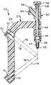
- FIG. 1is a partial perspective view of an instrumentation guide in accordance with the present invention.
- FIG. 2is a sectional perspective view of the instrumentation guide.
- FIG. 3is a sectional view of the instrumentation guide.
- FIG. 4is a sectional perspective partial view of the instrumentation guide and showing the attachment member.
- FIG. 5is another sectional perspective partial view of the instrumentation guide showing the attachment member.
- FIG. 6is an exploded view of the instrumentation guide.
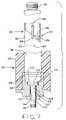
- FIG. 7is a partially cross sectional and exploded view of a second embodiment of the invention.
- the instrumentation guide 20includes a guide body 22 which, in the embodiment of FIGS. 1–6 , has a two piece construction with the two portions forming the guide body being a handle portion 24 and an insert 26 .
- Handle portion 24is formed out of a radio transparent material. Radio transparent materials which may be used to form handle portion 24 are well known in the art and one example of such a material is a composite material of poly ether ether ketone (PEEK) and carbon fibers such as that available from Greene, Tweed & Co. under the mark Orthtek.
- Insert 26is formed of a metallic material which, in the illustrated embodiment is a stainless steel.
- Instrumentation guide 20also includes an attachment member 28 and transfer member 30 which are both removable from the instrumentation guide 20 .
- both attachment member 28 and transfer member 30are formed of stainless steel.
- Attachment member 28includes external threads 32 disposed near one end of a shaft 34 .
- An enlarged generally cylindrical head 36is located on shaft 34 opposite threads 32 .
- Threads 32are used to engage the internal threads of an intramedullary rod or nail and thereby secure the rod or nail to instrumentation guide 20 as explained in greater detail below.
- Head 36includes a plurality of recesses or keyways 38 located circumferentially about its upper surface. The illustrated embodiment includes eight recesses 38 and an internally threaded opening 40 which are also discussed in greater detail below.
- Attachment member 28is removably captured in instrumentation guide 20 by insert 26 .
- insert 26has a passageway 27 or bore hole taking the form of a cylindrical opening extending therethrough. Attachment member 28 extends through the bore hole.
- the interior surface of the bore hole through insert 26includes a threaded portion defined by threads 42 which are sized to cooperate with threads 32 located on attachment member 28 .
- attachment member 28is secured to instrumentation guide 20 by inserting attachment member 28 through opening 45 ′ of handle portion 24 . Threads 32 are then turned through threads 42 to allow threads 32 and a portion of shaft 34 to pass through threads 42 .
- a non-threaded portion of shaft 34is located within threads 42 .
- attachment member 28After installation within guide body 22 , attachment member 28 includes a first portion, i.e., threaded end 32 , which projects outwardly therefrom for engagement with an intramedullary nail and a second portion, i.e., enlarged cylindrical head 36 , which is located in cavity 45 ′ of guide body 22 and is engageable with transfer member assemblage 30 as discussed below.
- first portioni.e., threaded end 32
- second portioni.e., enlarged cylindrical head 36
- Insert 26includes projections 44 which are configured to interfit with recesses on the end of an intramedullary nail 46 .
- Intramedullary rods or nails 46typically have one end which defines an internally threaded bore and has notches located in the rim of the bore to facilitate the rotational fixation of the nail while a threaded member is engaged with the internally threaded bore of the nail.
- Intramedullary rods or nails 46are secured to the instrumentation guide 20 by aligning and interfitting the notches located at one end of the nail or rod with projections 44 and then engaging threads 32 with the internally threaded bore of the nail until the nail is held firmly against insert 26 and thereby fixes the nail in a predetermined position with respect to guide body 22 .
- Attachment member 28is rotated with respect to guide body 22 by a T-handled driver (not shown) having an end which is inserted through opening 45 into cavity 45 ′ defined by guide body 22 .
- the inserted end of the T-handled driverincludes projections which matingly engage the recesses 38 of attachment member 28 for drivingly rotating member 28 while the guide body 22 is held stationary. After the nail 46 or rod is secured to instrumentation guide 20 , the transfer member 30 is attached.
- the illustrated embodimentincludes a transfer member 30 which takes the form of a transfer member assemblage having a first transfer member 48 and a second transfer member 50 .
- the illustrated embodimenthas a first transfer member formed by an inner elongate member or shaft 48 and the second transfer member is an outer body which forms a sleeve 50 within which shaft 48 is located. Both shaft 48 and outer sleeve 50 are formed out of stainless steel in the illustrated embodiment.
- Shaft 48includes a first threaded end 52 which engages the internally threaded opening 40 located on attachment member 28 .
- a shaft portion 54connects first end 52 with a second threaded end 56 of shaft 48 .
- Also located at the second end of shaft 48is an integral bolt head 58 .
- Bolt head 58is used to engage inner shaft 48 with attachment member 28 and thereby secure transfer member 30 to the instrumentation guide in a fixed position relative to the attachment member as described in greater detail below.
- Inner shaft 48is removably inserted into outer sleeve 50 and may be rotated with respect to sleeve 50 .
- a first end 60 of sleeve 50has a plurality of projections 62 which matingly engage with recesses 38 located on attachment member 28 .
- the illustrated embodimentemploys a plurality of projections and recesses located on the attachment member 28 and on sleeve 50 , alternative methods of rotationally securing these two components may also be employed.
- the first end of transfer member 30is inserted through opening 45 into cavity 45 ′ when engaging the first end of the transfer member assemblage 30 with attachment member 28 .
- first end 60 of sleeve 50 and its projections 62are engaged with recesses 38 located on attachment member 28 to rotationally secure sleeve 50 with member 28 , i.e., prevent relative rotational movement between sleeve 50 and member 28 .
- inner shaft 48is rotated relative to both outer sleeve 50 and attachment member 28 to threadingly engage threads 52 of shaft 48 with threaded opening 40 of attachment member 28 .
- Bolt head 58 located on inner shaft 48provides a mechanism for gripping and rotating shaft 48 whereas opening 64 located on sleeve 50 provides a mechanism for engaging sleeve 50 to thereby relatively rotate shaft 48 with respect to sleeve 50 and attachment member 28 which is rotationally engaged with sleeve 50 .
- transfer member 30is located within cavity 45 ′ when transfer member 30 is engaged with attachment member 28 .
- Transfer member 30may be engaged and disengaged with the attachment member 28 as discussed above while a nail 46 remains attached to the opposite side of the attachment member 28 .
- This enables the transfer member 30which may be substantially metallic, to be removed from guide body 22 during a surgical procedure.
- This ability to remove the transfer member 30facilitates the taking of radiographic images while the guide body 22 , which is substantially radio-transparent, remains firmly secured to a nail 46 in a predetermined position relative thereto after the nail has been inserted into an intramedullary canal. If necessary, the transfer member 30 can be re-engaged with the attachment member 28 with the nail 46 still attached to the opposite side of attachment member 28 .
- inner shaft 48includes a force receiving member which takes the form of a threaded projection 56 .
- a mushroom headed cap 66having an internally threaded opening can be attached to threaded projection 56 as shown in FIG. 3 .
- Cap 66can then be struck with a hammer, not shown, to drive nail 46 into an intramedullary canal.
- a slap hammerBy utilizing a removable cap 66 with inner shaft 48 , the wear caused by the direct impact of the hammer is primarily located on cap 66 which may be more cost effectively replaced than inner shaft 48 .
- a slap hammercan be threadingly attached to threaded projection 56 to impart insertion or removal forces to attached nail 46 .
- Slap hammersare well known in the art and typically have a weight with a grip mounted on a shaft whereby the weight may be slid along the shaft to impart a driving force upon impact in either direction.
- Outer sleeve 50includes a threaded projection 68 which is similar to threaded projection 56 such that either cap 66 or a slap hammer may be attached to projection 68 .
- the two force receiving members shown in the embodiment of FIGS. 1–6i.e., threaded projections 56 and 68 , are positioned to form an angle therebetween and both are positioned proximate the second end of transfer member 30 opposite attachment member 28 .
- Projection 68which is positioned at an angle to inner shaft 48 , is useful for some patients, such as obese patients, where the position of projection 68 provides access to transfer member 30 when access to threaded end 56 may be wholly or partially obstructed. Similar to threaded end 56 , threaded projection 68 facilitates the delivery of both insertion and removal forces.
- Insertion and removal forces imparted to inner shaft 48 through threaded end 56are transferred to attachment member 28 through the engagement of threads 52 and threaded opening 40 .
- Insertion forces imparted to projection 68are transferred to attachment member 28 by end 60 of sleeve 50 bearing against head 36 of attachment member 28 while the removal forces imparted to projection 68 are transferred to attachment member 28 by engagement of sleeve 50 with bolt head 58 , either directly or through an intermediate washer, inner shaft 48 then transfers the removal forces to attachment member 28 via threads 52 .
- the forces imparted to attachment member 28 from projection 68have a component force which is directed along the axis defined by shaft 54 and a transverse force perpendicular to shaft 54 .
- the outer portion of guide body 24can be gripped to counteract the forces imparted by projection 68 which are transverse to shaft 54 .
- instrumentation guide 20 illustrated in FIGS. 1–6includes a transfer member 30 which directly engages and directly transmits forces to attachment member 28
- transfer member 30 of instrumentation guide 20could alternatively engage a different component of instrumentation guide 20 provided that the insertion and removal forces conveyed by transfer member 30 were transferred through intermediate parts to attachment member 28 .
- guide body 22includes alignment features 70 which, in the illustrated embodiment, take the form of bore holes. Since nail 46 is securable to guide body 22 in a predetermined position relative to the guide body 22 , alignment features 70 can be positioned to align with transverse openings in the nail 46 to facilitate the insertion of screws 72 therethrough in a manner well known in the art. Dashed lines 78 illustrate how alignment features 70 provide a reference axis for use when installing a screw 72 in a transverse opening in a nail 46 . As can be seen in FIG. 6 , instrumentation, including a bushing 74 and drill 76 may be used to install screws 72 .
- insert 26is metallic. By limiting metallic insert 26 to the area proximate attachment member 28 , the obscuration of the radiographic images by insert 26 can also be limited while enabling such details as threads 42 to be formed out of a metallic material.
- FIG. 7An alternative embodiment of the present invention is shown in FIG. 7 .
- the embodiment shown in FIG. 7includes a transfer member 80 having a non-threaded quick connect mechanism 82 which secures transfer member 80 to guide body 90 in a fixed relative position to attachment member 100 .
- the quick connect mechanism 82is both engageable and disengageable with the instrumentation guide when an orthopedic device, such as an intramedullary nail 46 or rod, is attached to attachment member 100 .
- the quick connect mechanism 82includes a plurality of spherical bearings 84 which project through openings in the transfer member 80 and are biased outwardly by a downwardly biased plunger 86 .
- a biasing element 88is schematically illustrated in FIG. 7 and is used to bias the plunger 86 downward. Biasing element 88 may include a spring to provide a biasing force.
- a release mechanism(not shown) may be located on the transfer member 80 to facilitate the disengagement of quick connect mechanism 82 . If the biasing force exerted on plunger 86 is not excessive, a release mechanism may not be required.
- a projection 89is located on the bottom of transfer member 80 and is engageable with the recess 102 located on head 104 of attachment member 100 .
- Guide body 90includes a first portion 92 which is a radio-transparent body having alignment features similar to handle portion 24 , and a second portion 94 which is a metallic insert member. Insert member 94 may advantageously include a knurled surface where it engages first portion 92 . Guide body 90 also defines a cavity 96 which takes the form of a cylindrical bore and receives the end of transfer member 80 .
- Insert 94includes a groove 98 which receives bearings 84 to thereby engage guide body 90 with transfer member 80 through quick connect mechanism 82 .
- Alternative shapes of grooves and bearingsmay also be employed with quick connect mechanism 82 .
- Alternative forms of known quick connect mechanismsmay also be employed with transfer member 80 .
- Insert 94also includes a passageway 106 which includes threads 108 which function similar to threads 42 .
- Insert 94also includes projections 110 which interfit with an attached nail 46 similar to projections 44 discussed above.
- intramedullary nailsare handed, i.e., designed for use on the left or right side of a patient such as in the left or right femur. Such nails often have differently configured notches and may require the use of two different instrumentation guides having differently configured projections 44 or 110 . It is envisioned that mounting projections 110 in a manner which permits their rotation by 180 degrees relative to insert 94 would allow the same guide body 90 to be used with both “left” and “right” nails 46 .
- Attachment member 100includes a threaded end 112 and shaft 114 which are similar to threaded end 32 and shaft 34 of attachment member 28 .
- Head 104includes a recess 102 which has a lower portion which is engageable by a hex head driver (not shown) to secure threaded end 112 to a nail 46 or similar orthopedic device.
- Projection 89is seated within the upper portion of recess 102 when quick connect mechanism 82 is engaged with insert 94 .
- Lower surface 87 of transfer member 80bears against the upper surface 105 of head 104 to impart insertion forces to attachment member 100 .
- Transfer member 80includes a force receiving member 116 at its end opposite projection 89 .
- Member 116is a threaded projection which functions similar to threaded projections 56 and 68 .
- Alternative force receiving memberscould also be employed. Although illustrated transfer member 80 takes the form of a straight elongate member, using a pivot mechanism with transfer member 80 would allow force receiving member 116 to be placed at a variety of different positions relative to projection 89 .
Landscapes
- Health & Medical Sciences (AREA)
- Surgery (AREA)
- Life Sciences & Earth Sciences (AREA)
- Orthopedic Medicine & Surgery (AREA)
- Biomedical Technology (AREA)
- Nuclear Medicine, Radiotherapy & Molecular Imaging (AREA)
- Engineering & Computer Science (AREA)
- Heart & Thoracic Surgery (AREA)
- Medical Informatics (AREA)
- Molecular Biology (AREA)
- Animal Behavior & Ethology (AREA)
- General Health & Medical Sciences (AREA)
- Public Health (AREA)
- Veterinary Medicine (AREA)
- Oral & Maxillofacial Surgery (AREA)
- Dentistry (AREA)
- Surgical Instruments (AREA)
Abstract
Description
Claims (20)
Priority Applications (1)
| Application Number | Priority Date | Filing Date | Title |
|---|---|---|---|
| US10/280,838US7144399B2 (en) | 2002-10-25 | 2002-10-25 | Instrumentation guide for orthopedic surgery |
Applications Claiming Priority (1)
| Application Number | Priority Date | Filing Date | Title |
|---|---|---|---|
| US10/280,838US7144399B2 (en) | 2002-10-25 | 2002-10-25 | Instrumentation guide for orthopedic surgery |
Publications (2)
| Publication Number | Publication Date |
|---|---|
| US20040082959A1 US20040082959A1 (en) | 2004-04-29 |
| US7144399B2true US7144399B2 (en) | 2006-12-05 |
Family
ID=32107032
Family Applications (1)
| Application Number | Title | Priority Date | Filing Date |
|---|---|---|---|
| US10/280,838Expired - Fee RelatedUS7144399B2 (en) | 2002-10-25 | 2002-10-25 | Instrumentation guide for orthopedic surgery |
Country Status (1)
| Country | Link |
|---|---|
| US (1) | US7144399B2 (en) |
Cited By (39)
| Publication number | Priority date | Publication date | Assignee | Title |
|---|---|---|---|---|
| US20040138671A1 (en)* | 2002-11-02 | 2004-07-15 | Stryker Trauma Gmbh | Targeting device for a locking nail |
| US20060161168A1 (en)* | 2003-07-14 | 2006-07-20 | Romano Matthys | Targeting device |
| US20080125782A1 (en)* | 2006-11-29 | 2008-05-29 | Disc Dynamics, Inc. | Method and apparatus for removing an extension from a prosthesis |
| US20090093813A1 (en)* | 2007-10-04 | 2009-04-09 | Ebi, L.P. | Alignment device for locking nail |
| US20090299375A1 (en)* | 2008-06-03 | 2009-12-03 | Zimmer, Inc. | Catheter nail targeting guide |
| US20100121324A1 (en)* | 2008-06-24 | 2010-05-13 | Jeff Tyber | Fixation system, an intramedullary fixation assembly and method of use |
| US7846162B2 (en) | 2005-05-18 | 2010-12-07 | Sonoma Orthopedic Products, Inc. | Minimally invasive actuable bone fixation devices |
| US20100312244A1 (en)* | 2009-06-04 | 2010-12-09 | Edwards Scott G | Intramedullary device assembly and associated method |
| US7909825B2 (en) | 2006-11-22 | 2011-03-22 | Sonoma Orthepedic Products, Inc. | Fracture fixation device, tools and methods |
| US20120095560A1 (en)* | 2010-01-13 | 2012-04-19 | Jcbd, Llc | Systems for and methods of fusing a sacroiliac joint |
| US8287541B2 (en) | 2005-05-18 | 2012-10-16 | Sonoma Orthopedic Products, Inc. | Fracture fixation device, tools and methods |
| US8313487B2 (en) | 2008-06-24 | 2012-11-20 | Extremity Medical Llc | Fixation system, an intramedullary fixation assembly and method of use |
| US8328806B2 (en) | 2008-06-24 | 2012-12-11 | Extremity Medical, Llc | Fixation system, an intramedullary fixation assembly and method of use |
| US8343199B2 (en) | 2008-06-24 | 2013-01-01 | Extremity Medical, Llc | Intramedullary fixation screw, a fixation system, and method of fixation of the subtalar joint |
| US8562606B2 (en) | 2009-12-11 | 2013-10-22 | Small Bone Innovations, Inc. | Ankle fusion device, instrumentation and methods |
| US8961516B2 (en) | 2005-05-18 | 2015-02-24 | Sonoma Orthopedic Products, Inc. | Straight intramedullary fracture fixation devices and methods |
| US8979847B2 (en) | 2011-06-06 | 2015-03-17 | Biomet Manufacturing, Llc | Method and apparatus for implanting a knee prosthesis |
| US9017329B2 (en) | 2008-06-24 | 2015-04-28 | Extremity Medical, Llc | Intramedullary fixation assembly and method of use |
| US9023051B2 (en) | 2011-02-22 | 2015-05-05 | Zimmer Knee Creations, Inc. | Navigation and positioning systems and guide instruments for joint repair |
| US20150133936A1 (en)* | 2008-06-24 | 2015-05-14 | Extremity Medical L.L.C. | Intraosseous intramedullary fixation assembly and method of use |
| US9060820B2 (en) | 2005-05-18 | 2015-06-23 | Sonoma Orthopedic Products, Inc. | Segmented intramedullary fracture fixation devices and methods |
| US9155574B2 (en) | 2006-05-17 | 2015-10-13 | Sonoma Orthopedic Products, Inc. | Bone fixation device, tools and methods |
| US9289220B2 (en) | 2008-06-24 | 2016-03-22 | Extremity Medical Llc | Intramedullary fixation assembly and method of use |
| US9333090B2 (en) | 2010-01-13 | 2016-05-10 | Jcbd, Llc | Systems for and methods of fusing a sacroiliac joint |
| US9381045B2 (en) | 2010-01-13 | 2016-07-05 | Jcbd, Llc | Sacroiliac joint implant and sacroiliac joint instrument for fusing a sacroiliac joint |
| US9421109B2 (en) | 2010-01-13 | 2016-08-23 | Jcbd, Llc | Systems and methods of fusing a sacroiliac joint |
| US9554909B2 (en) | 2012-07-20 | 2017-01-31 | Jcbd, Llc | Orthopedic anchoring system and methods |
| US9700356B2 (en) | 2013-07-30 | 2017-07-11 | Jcbd, Llc | Systems for and methods of fusing a sacroiliac joint |
| US9717539B2 (en) | 2013-07-30 | 2017-08-01 | Jcbd, Llc | Implants, systems, and methods for fusing a sacroiliac joint |
| US9770278B2 (en) | 2014-01-17 | 2017-09-26 | Arthrex, Inc. | Dual tip guide wire |
| US9788961B2 (en) | 2010-01-13 | 2017-10-17 | Jcbd, Llc | Sacroiliac joint implant system |
| US9801546B2 (en) | 2014-05-27 | 2017-10-31 | Jcbd, Llc | Systems for and methods of diagnosing and treating a sacroiliac joint disorder |
| US9814499B2 (en) | 2014-09-30 | 2017-11-14 | Arthrex, Inc. | Intramedullary fracture fixation devices and methods |
| US9826986B2 (en) | 2013-07-30 | 2017-11-28 | Jcbd, Llc | Systems for and methods of preparing a sacroiliac joint for fusion |
| US10245087B2 (en) | 2013-03-15 | 2019-04-02 | Jcbd, Llc | Systems and methods for fusing a sacroiliac joint and anchoring an orthopedic appliance |
| US20190105093A1 (en)* | 2017-10-10 | 2019-04-11 | DePuy Synthes Products, Inc. | Self-retaining nail to insertion handle interface |
| US10603055B2 (en) | 2017-09-15 | 2020-03-31 | Jcbd, Llc | Systems for and methods of preparing and fusing a sacroiliac joint |
| US11504171B2 (en) | 2019-07-26 | 2022-11-22 | Glw, Inc. | Intramedullary rod with intrabody outrigger interface |
| US20220378484A1 (en)* | 2021-05-28 | 2022-12-01 | Acumed Llc | Bone fixation systems and nail having compressive threading |
Families Citing this family (15)
| Publication number | Priority date | Publication date | Assignee | Title |
|---|---|---|---|---|
| US9192398B2 (en)* | 2005-09-19 | 2015-11-24 | DePuy Synthes Products, Inc. | Orthopedic implant insertion handle and aiming guide |
| US8491595B2 (en) | 2006-10-30 | 2013-07-23 | Depuy Mitek, Llc | Methods and devices for ligament repair |
| US8784430B2 (en)* | 2007-04-26 | 2014-07-22 | Zimmer, Inc. | Nail cap cannula |
| US20090112209A1 (en)* | 2007-10-31 | 2009-04-30 | Zimmer, Inc. | Implantation system for intramedullary nail and related methods for implanting intramedullary nails |
| US20110230884A1 (en)* | 2008-06-24 | 2011-09-22 | Adam Mantzaris | Hybrid intramedullary fixation assembly and method of use |
| AU2009222580B2 (en) | 2008-10-10 | 2014-11-27 | Depuy Mitek, Inc. | Method for replacing a ligament in a knee |
| JP2010251529A (en)* | 2009-04-16 | 2010-11-04 | Sony Corp | Semiconductor memory device and manufacturing method thereof |
| US8932301B2 (en)* | 2009-08-26 | 2015-01-13 | Biomet C.V. | Targeting jig for hip fracture nail system |
| EP2496160B1 (en)* | 2009-11-06 | 2017-08-23 | Mark Crawford | Spinal surgery apparatus and method |
| CN102151171B (en)* | 2011-03-15 | 2012-09-26 | 平阴县人民医院 | Broken-nail extractor for orthopedics and using method thereof |
| US8617176B2 (en) | 2011-08-24 | 2013-12-31 | Depuy Mitek, Llc | Cross pinning guide devices and methods |
| WO2015038196A1 (en)* | 2013-04-24 | 2015-03-19 | Doyle Michael J | Vertebral interbody fusion tool and related methods |
| JP6687595B2 (en)* | 2014-07-15 | 2020-04-22 | オーティ メディツィンテヒニック ゲーエムベーハー | Positioning device for fixing intramedullary nail to long bone |
| US10966773B2 (en)* | 2017-07-31 | 2021-04-06 | DePuy Synthes Products, Inc. | Correction guide for femoral neck |
| CN112155710B (en)* | 2020-09-17 | 2021-08-03 | 鹤壁市人民医院 | Nail taking device for orthopedics department |
Citations (19)
| Publication number | Priority date | Publication date | Assignee | Title |
|---|---|---|---|---|
| US4570624A (en) | 1983-08-10 | 1986-02-18 | Henry Ford Hospital | Universal guide for inserting parallel pins |
| US4622959A (en) | 1985-03-05 | 1986-11-18 | Marcus Randall E | Multi-use femoral intramedullary nail |
| US4805607A (en) | 1987-12-03 | 1989-02-21 | Boehringer Mannheim Corporation | Modular intramedullary nail system |
| US4881535A (en) | 1988-09-06 | 1989-11-21 | Sohngen Gary W | Intramedullary rod targeting device |
| US4911153A (en) | 1988-02-04 | 1990-03-27 | Biomet, Inc. | Orthopedic surgical instrument |
| GB2230453A (en)* | 1989-04-18 | 1990-10-24 | Neoligaments Ltd | Instrument for use in knee surgery |
| US4969889A (en) | 1986-12-22 | 1990-11-13 | Zimmer, Inc. | Instrument for locating a hole |
| US4978351A (en) | 1988-09-28 | 1990-12-18 | Rozas Fernando C | Guiding instrument to pierce the bone cortical, auxiliary in the location of the holes for intra-marrow pins |
| US5100404A (en)* | 1990-09-04 | 1992-03-31 | Beth Israel Hospital | Intramedullary nailing method and apparatus |
| US5178621A (en)* | 1991-12-10 | 1993-01-12 | Zimmer, Inc. | Two-piece radio-transparent proximal targeting device for a locking intramedullary nail |
| US5334205A (en)* | 1993-06-30 | 1994-08-02 | The United States Of America As Represented By The Secretary Of The Air Force | Sacroiliac joint fixation guide |
| US5478341A (en) | 1991-12-23 | 1995-12-26 | Zimmer, Inc. | Ratchet lock for an intramedullary nail locking bolt |
| US5514139A (en) | 1994-09-02 | 1996-05-07 | Hudson Surgical Design, Inc. | Method and apparatus for femoral resection |
| US5597379A (en) | 1994-09-02 | 1997-01-28 | Hudson Surgical Design, Inc. | Method and apparatus for femoral resection alignment |
| US5643272A (en) | 1994-09-02 | 1997-07-01 | Hudson Surgical Design, Inc. | Method and apparatus for tibial resection |
| US5688271A (en)* | 1994-03-07 | 1997-11-18 | Orthofix S.R.L. | Orthopaedic device, especially for the gradual correction of fractures |
| US5755803A (en) | 1994-09-02 | 1998-05-26 | Hudson Surgical Design | Prosthetic implant |
| US5810827A (en) | 1994-09-02 | 1998-09-22 | Hudson Surgical Design, Inc. | Method and apparatus for bony material removal |
| US6695848B2 (en) | 1994-09-02 | 2004-02-24 | Hudson Surgical Design, Inc. | Methods for femoral and tibial resection |
Family Cites Families (67)
| Publication number | Priority date | Publication date | Assignee | Title |
|---|---|---|---|---|
| US604119A (en)* | 1898-05-17 | Surgical needle | ||
| US430826A (en)* | 1890-06-24 | Fish-string needle | ||
| US919138A (en)* | 1909-03-16 | 1909-04-20 | Clarence A Drake | Surgical needle. |
| US1583271A (en)* | 1925-01-14 | 1926-05-04 | Biro Ladislaus | Surgical instrument |
| US1757129A (en)* | 1928-02-16 | 1930-05-06 | William L Mcclure | Atraumatic rethreadable surgical needle |
| US1822330A (en)* | 1930-01-13 | 1931-09-08 | Ainslie George | Suturing instrument |
| US2327353A (en)* | 1940-12-12 | 1943-08-24 | Singer Mfg Co | Instrument for suturing |
| US2439383A (en)* | 1946-07-19 | 1948-04-13 | Lester H Erickson | Surgical stitching instrument |
| US2581564A (en)* | 1949-10-20 | 1952-01-08 | Villegas Jaime | Atraumatic surgical needle |
| US2959172A (en)* | 1957-08-27 | 1960-11-08 | American Cystoscope Makers Inc | Self-threading suturing instrument |
| US2940451A (en)* | 1958-02-26 | 1960-06-14 | Canadian Patents Dev | Suturing apparatus |
| US3074409A (en)* | 1959-12-28 | 1963-01-22 | Ernst Kratz | Surgical needle for medical purposes |
| US3090386A (en)* | 1961-07-20 | 1963-05-21 | Curtis Scott Company | Surgical suturing instrument |
| US3344790A (en)* | 1964-11-02 | 1967-10-03 | Richard L Dorner | Surgical suturing device with auxiliary spool-brake means |
| US3807407A (en)* | 1971-06-07 | 1974-04-30 | E Schweizer | Suture applicator |
| US3901244A (en)* | 1973-05-07 | 1975-08-26 | Edward E Schweizer | Suture cartridge |
| US3946740A (en)* | 1974-10-15 | 1976-03-30 | Bassett John W | Suturing device |
| US4027608A (en)* | 1976-02-20 | 1977-06-07 | Raymond Kelder | Suturing device |
| US4109658A (en)* | 1977-02-04 | 1978-08-29 | Hughes Joe L | Needle holding device with pick-up means |
| US4235177A (en)* | 1979-02-23 | 1980-11-25 | Raymond C. Kelder | Suturing device |
| US4345601A (en)* | 1980-04-07 | 1982-08-24 | Mamoru Fukuda | Continuous suturing device |
| US4406237A (en)* | 1980-05-23 | 1983-09-27 | Janome Sewing Machine Co. Ltd. | Suturing instrument for surgical operation |
| JPS571332A (en)* | 1980-06-06 | 1982-01-06 | Janome Sewing Machine Co Ltd | Catching of needle yarn loop of operation suturing device |
| JPS6245693Y2 (en)* | 1981-03-20 | 1987-12-07 | ||
| JPS57170239A (en)* | 1981-04-13 | 1982-10-20 | Janome Sewing Machine Co Ltd | Holding of shuttle of suturing device for operation |
| US4576166A (en)* | 1981-06-29 | 1986-03-18 | American Cyanamid Company | Surgical ligating instrument |
| US4509518A (en)* | 1982-02-17 | 1985-04-09 | United States Surgical Corporation | Apparatus for applying surgical clips |
| US4448193A (en)* | 1982-02-26 | 1984-05-15 | Ethicon, Inc. | Surgical clip applier with circular clip magazine |
| SE441643B (en)* | 1983-02-08 | 1985-10-28 | Innova Ab | suturing instrument |
| US4462395A (en)* | 1983-03-02 | 1984-07-31 | Johnson Lanny L | Arthroscopic ligamentous and capsular fixation system |
| US4596249A (en)* | 1983-07-26 | 1986-06-24 | Freda Vincent J | Implement for setting sutures |
| US4621640A (en)* | 1984-01-09 | 1986-11-11 | Mulhollan James S | Mechanical needle carrier and method for its use |
| US4598711A (en)* | 1984-08-09 | 1986-07-08 | American Cyanamid Company | Surgical instrument |
| US4799483A (en)* | 1988-02-11 | 1989-01-24 | Kraff Manus C | Suturing needle with tail mounted cutting blade and method for using same |
| US4899746A (en)* | 1988-04-28 | 1990-02-13 | Brunk Industries, Inc. | Suturing apparatus |
| DE69123161T2 (en)* | 1990-02-06 | 1997-03-13 | Fujitsu Ltd | Superconducting circuit with an output conversion circuit |
| US5389102A (en)* | 1990-09-13 | 1995-02-14 | United States Surgical Corporation | Apparatus and method for subcuticular stapling of body tissue |
| JP2545558Y2 (en)* | 1990-10-23 | 1997-08-25 | ジョンソン・エンド・ジョンソンメディカル株式会社 | Deep suture instrument |
| DK166600B1 (en)* | 1991-01-17 | 1993-06-21 | Therkel Bisgaard | TOOL USE TOUCH BY SUTURING IN DEEP OPERATING OPENINGS OR BODY SPACES |
| US5152769A (en)* | 1991-11-04 | 1992-10-06 | Will Baber | Apparatus for laparoscopic suturing with improved suture needle |
| US5417700A (en)* | 1992-03-30 | 1995-05-23 | Thomas D. Egan | Automatic suturing and ligating device |
| US5312422A (en)* | 1992-07-16 | 1994-05-17 | Linvatec Corporation | Endoscopic suturing needle |
| US5308353A (en)* | 1992-08-31 | 1994-05-03 | Merrimac Industries, Inc. | Surgical suturing device |
| US5306281A (en)* | 1992-08-31 | 1994-04-26 | Merrimac Industries, Inc. | Suturing cassette device |
| US6048351A (en)* | 1992-09-04 | 2000-04-11 | Scimed Life Systems, Inc. | Transvaginal suturing system |
| US5364408A (en)* | 1992-09-04 | 1994-11-15 | Laurus Medical Corporation | Endoscopic suture system |
| US5713910A (en)* | 1992-09-04 | 1998-02-03 | Laurus Medical Corporation | Needle guidance system for endoscopic suture device |
| DE4304353A1 (en)* | 1992-10-24 | 1994-04-28 | Helmut Dipl Ing Wurster | Suturing device used in endoscopic surgical operations - has helical needle with fixed non-traumatic thread held and rotated by rollers attached to instrument head extended into patients body. |
| US5876325A (en)* | 1993-11-02 | 1999-03-02 | Olympus Optical Co., Ltd. | Surgical manipulation system |
| US5431666A (en)* | 1994-02-24 | 1995-07-11 | Lasersurge, Inc. | Surgical suture instrument |
| US5571090A (en)* | 1994-10-07 | 1996-11-05 | United States Surgical Corporation | Vascular suturing apparatus |
| US5720755A (en)* | 1995-01-18 | 1998-02-24 | Dakov; Pepi | Tubular suturing device and methods of use |
| US5540705A (en)* | 1995-05-19 | 1996-07-30 | Suturtek, Inc. | Suturing instrument with thread management |
| US5709893A (en)* | 1995-06-06 | 1998-01-20 | The Boeing Company | Breathable tooling for forming parts from volatile-emitting composite materials |
| US5709693A (en)* | 1996-02-20 | 1998-01-20 | Cardiothoracic System, Inc. | Stitcher |
| US5814054A (en)* | 1996-09-23 | 1998-09-29 | Symbiosis Corporation | Automatic needle-passer suturing instrument |
| US5984932A (en)* | 1996-11-27 | 1999-11-16 | Yoon; Inbae | Suturing instrument with one or more spreadable needle holders mounted for arcuate movement |
| US5993466A (en)* | 1997-06-17 | 1999-11-30 | Yoon; Inbae | Suturing instrument with multiple rotatably mounted spreadable needle holders |
| US5728108A (en)* | 1997-03-20 | 1998-03-17 | Tnco, Inc. | Rotary drive mechanism for instrument handle |
| WO1999007441A1 (en)* | 1997-08-11 | 1999-02-18 | Mayer Paul W | Motorized motion-canceling suture tool holder |
| IL121752A0 (en)* | 1997-09-11 | 1998-02-22 | Gaber Benny | Stitching tool |
| US6077278A (en)* | 1997-09-17 | 2000-06-20 | Mayer; Paul W. | Suture needle holder |
| US5919199A (en)* | 1998-01-14 | 1999-07-06 | Mers Kelly; William Charles | Suture device |
| WO1999055237A1 (en)* | 1998-04-29 | 1999-11-04 | Inbae Yoon | Instrument and method of suturing anatomical tissue and tying suture material |
| WO1999065398A1 (en)* | 1998-06-17 | 1999-12-23 | Inbae Yoon | Suturing instrument with angled needle holder and method for use thereof |
| US6221084B1 (en)* | 1999-01-15 | 2001-04-24 | Pare Surgical, Inc. | Knot tying apparatus having a notched thread cover and method for using same |
| US6437681B1 (en)* | 1999-10-27 | 2002-08-20 | Cyntec Company | Structure and fabrication process for an improved high temperature sensor |
- 2002
- 2002-10-25USUS10/280,838patent/US7144399B2/ennot_activeExpired - Fee Related
Patent Citations (22)
| Publication number | Priority date | Publication date | Assignee | Title |
|---|---|---|---|---|
| US4570624A (en) | 1983-08-10 | 1986-02-18 | Henry Ford Hospital | Universal guide for inserting parallel pins |
| US4622959A (en) | 1985-03-05 | 1986-11-18 | Marcus Randall E | Multi-use femoral intramedullary nail |
| US4969889A (en) | 1986-12-22 | 1990-11-13 | Zimmer, Inc. | Instrument for locating a hole |
| US4805607A (en) | 1987-12-03 | 1989-02-21 | Boehringer Mannheim Corporation | Modular intramedullary nail system |
| US4911153A (en) | 1988-02-04 | 1990-03-27 | Biomet, Inc. | Orthopedic surgical instrument |
| US4881535A (en) | 1988-09-06 | 1989-11-21 | Sohngen Gary W | Intramedullary rod targeting device |
| US4978351A (en) | 1988-09-28 | 1990-12-18 | Rozas Fernando C | Guiding instrument to pierce the bone cortical, auxiliary in the location of the holes for intra-marrow pins |
| GB2230453A (en)* | 1989-04-18 | 1990-10-24 | Neoligaments Ltd | Instrument for use in knee surgery |
| US5100404A (en)* | 1990-09-04 | 1992-03-31 | Beth Israel Hospital | Intramedullary nailing method and apparatus |
| US5178621A (en)* | 1991-12-10 | 1993-01-12 | Zimmer, Inc. | Two-piece radio-transparent proximal targeting device for a locking intramedullary nail |
| US5478341A (en) | 1991-12-23 | 1995-12-26 | Zimmer, Inc. | Ratchet lock for an intramedullary nail locking bolt |
| US5334205A (en)* | 1993-06-30 | 1994-08-02 | The United States Of America As Represented By The Secretary Of The Air Force | Sacroiliac joint fixation guide |
| US5688271A (en)* | 1994-03-07 | 1997-11-18 | Orthofix S.R.L. | Orthopaedic device, especially for the gradual correction of fractures |
| US5514139A (en) | 1994-09-02 | 1996-05-07 | Hudson Surgical Design, Inc. | Method and apparatus for femoral resection |
| US5597379A (en) | 1994-09-02 | 1997-01-28 | Hudson Surgical Design, Inc. | Method and apparatus for femoral resection alignment |
| US5643272A (en) | 1994-09-02 | 1997-07-01 | Hudson Surgical Design, Inc. | Method and apparatus for tibial resection |
| US5755803A (en) | 1994-09-02 | 1998-05-26 | Hudson Surgical Design | Prosthetic implant |
| US5810827A (en) | 1994-09-02 | 1998-09-22 | Hudson Surgical Design, Inc. | Method and apparatus for bony material removal |
| US5879354A (en) | 1994-09-02 | 1999-03-09 | Hudson Surgical Design, Inc. | Prosthetic implant |
| US6056754A (en) | 1994-09-02 | 2000-05-02 | Hudson Surgical Design, Inc. | Method and apparatus for patella resection and guide handle |
| US6197064B1 (en) | 1994-09-02 | 2001-03-06 | Hudson Surgical Design, Inc. | Prosthetic implant |
| US6695848B2 (en) | 1994-09-02 | 2004-02-24 | Hudson Surgical Design, Inc. | Methods for femoral and tibial resection |
Cited By (69)
| Publication number | Priority date | Publication date | Assignee | Title |
|---|---|---|---|---|
| US7549994B2 (en)* | 2002-11-02 | 2009-06-23 | Stryker Trauma Gmbh | Targeting device for a locking nail |
| US20040138671A1 (en)* | 2002-11-02 | 2004-07-15 | Stryker Trauma Gmbh | Targeting device for a locking nail |
| US20060161168A1 (en)* | 2003-07-14 | 2006-07-20 | Romano Matthys | Targeting device |
| US8114093B2 (en)* | 2003-07-14 | 2012-02-14 | Synthes Usa, Llc | Targeting device |
| US7942875B2 (en) | 2005-05-18 | 2011-05-17 | Sonoma Orthopedic Products, Inc. | Methods of using minimally invasive actuable bone fixation devices |
| US9060820B2 (en) | 2005-05-18 | 2015-06-23 | Sonoma Orthopedic Products, Inc. | Segmented intramedullary fracture fixation devices and methods |
| US8287539B2 (en) | 2005-05-18 | 2012-10-16 | Sonoma Orthopedic Products, Inc. | Fracture fixation device, tools and methods |
| US8287541B2 (en) | 2005-05-18 | 2012-10-16 | Sonoma Orthopedic Products, Inc. | Fracture fixation device, tools and methods |
| US8961516B2 (en) | 2005-05-18 | 2015-02-24 | Sonoma Orthopedic Products, Inc. | Straight intramedullary fracture fixation devices and methods |
| US7846162B2 (en) | 2005-05-18 | 2010-12-07 | Sonoma Orthopedic Products, Inc. | Minimally invasive actuable bone fixation devices |
| US7914533B2 (en) | 2005-05-18 | 2011-03-29 | Sonoma Orthopedic Products, Inc. | Minimally invasive actuable bone fixation devices |
| US9155574B2 (en) | 2006-05-17 | 2015-10-13 | Sonoma Orthopedic Products, Inc. | Bone fixation device, tools and methods |
| US7909825B2 (en) | 2006-11-22 | 2011-03-22 | Sonoma Orthepedic Products, Inc. | Fracture fixation device, tools and methods |
| US8439917B2 (en) | 2006-11-22 | 2013-05-14 | Sonoma Orthopedic Products, Inc. | Fracture fixation device, tools and methods |
| US9259250B2 (en) | 2006-11-22 | 2016-02-16 | Sonoma Orthopedic Products, Inc. | Fracture fixation device, tools and methods |
| US20080125782A1 (en)* | 2006-11-29 | 2008-05-29 | Disc Dynamics, Inc. | Method and apparatus for removing an extension from a prosthesis |
| US8273091B2 (en)* | 2007-10-04 | 2012-09-25 | Ebi, Llc | Alignment device for locking nail |
| US20090093813A1 (en)* | 2007-10-04 | 2009-04-09 | Ebi, L.P. | Alignment device for locking nail |
| WO2009148903A2 (en) | 2008-06-03 | 2009-12-10 | Zimmer, Inc. | Catheter nail targeting guide |
| US20090299375A1 (en)* | 2008-06-03 | 2009-12-03 | Zimmer, Inc. | Catheter nail targeting guide |
| US8900274B2 (en) | 2008-06-24 | 2014-12-02 | Extremity Medical Llc | Fixation system, an intramedullary fixation assembly and method of use |
| US8313487B2 (en) | 2008-06-24 | 2012-11-20 | Extremity Medical Llc | Fixation system, an intramedullary fixation assembly and method of use |
| US8328806B2 (en) | 2008-06-24 | 2012-12-11 | Extremity Medical, Llc | Fixation system, an intramedullary fixation assembly and method of use |
| US8343199B2 (en) | 2008-06-24 | 2013-01-01 | Extremity Medical, Llc | Intramedullary fixation screw, a fixation system, and method of fixation of the subtalar joint |
| US8303589B2 (en)* | 2008-06-24 | 2012-11-06 | Extremity Medical Llc | Fixation system, an intramedullary fixation assembly and method of use |
| US9044282B2 (en) | 2008-06-24 | 2015-06-02 | Extremity Medical Llc | Intraosseous intramedullary fixation assembly and method of use |
| US20150133936A1 (en)* | 2008-06-24 | 2015-05-14 | Extremity Medical L.L.C. | Intraosseous intramedullary fixation assembly and method of use |
| US20100121324A1 (en)* | 2008-06-24 | 2010-05-13 | Jeff Tyber | Fixation system, an intramedullary fixation assembly and method of use |
| US8920453B2 (en) | 2008-06-24 | 2014-12-30 | Extremity Medical, Llc | Fixation system, an intramedullary fixation assembly and method of use |
| US8920476B2 (en) | 2008-06-24 | 2014-12-30 | Extremity Medical, Llc | Fixation system, an intramedullary fixation assembly and method of use |
| US9017329B2 (en) | 2008-06-24 | 2015-04-28 | Extremity Medical, Llc | Intramedullary fixation assembly and method of use |
| US9289220B2 (en) | 2008-06-24 | 2016-03-22 | Extremity Medical Llc | Intramedullary fixation assembly and method of use |
| US9364271B2 (en)* | 2008-06-24 | 2016-06-14 | Extremity Medical Llc | Intraosseous intramedullary fixation assembly and method of use |
| US20100312244A1 (en)* | 2009-06-04 | 2010-12-09 | Edwards Scott G | Intramedullary device assembly and associated method |
| US8216237B2 (en) | 2009-06-04 | 2012-07-10 | Edwards Scott G | Intramedullary device assembly and associated method |
| US20120265201A1 (en)* | 2009-06-04 | 2012-10-18 | Olecranail Llc | Intramedullary device assembly and associated method |
| US9308037B2 (en) | 2009-12-11 | 2016-04-12 | Stryker European Holdings I, Llc | Ankle fusion device, instrumentation and methods |
| US8562606B2 (en) | 2009-12-11 | 2013-10-22 | Small Bone Innovations, Inc. | Ankle fusion device, instrumentation and methods |
| US9017407B2 (en)* | 2010-01-13 | 2015-04-28 | Jcbd, Llc | Systems for and methods of fusing a sacroiliac joint |
| US9788961B2 (en) | 2010-01-13 | 2017-10-17 | Jcbd, Llc | Sacroiliac joint implant system |
| US10034676B2 (en) | 2010-01-13 | 2018-07-31 | Jcbd, Llc | Systems for and methods of fusing a sacroiliac joint |
| US8979928B2 (en) | 2010-01-13 | 2015-03-17 | Jcbd, Llc | Sacroiliac joint fixation fusion system |
| US8808377B2 (en) | 2010-01-13 | 2014-08-19 | Jcbd, Llc | Sacroiliac joint fixation system |
| US9333090B2 (en) | 2010-01-13 | 2016-05-10 | Jcbd, Llc | Systems for and methods of fusing a sacroiliac joint |
| US20120095560A1 (en)* | 2010-01-13 | 2012-04-19 | Jcbd, Llc | Systems for and methods of fusing a sacroiliac joint |
| US9381045B2 (en) | 2010-01-13 | 2016-07-05 | Jcbd, Llc | Sacroiliac joint implant and sacroiliac joint instrument for fusing a sacroiliac joint |
| US9421109B2 (en) | 2010-01-13 | 2016-08-23 | Jcbd, Llc | Systems and methods of fusing a sacroiliac joint |
| US9775639B2 (en) | 2011-02-22 | 2017-10-03 | Zimmer Knee Creations, Inc. | Navigation and positioning systems and guide instruments for joint repair |
| US9023051B2 (en) | 2011-02-22 | 2015-05-05 | Zimmer Knee Creations, Inc. | Navigation and positioning systems and guide instruments for joint repair |
| US8979847B2 (en) | 2011-06-06 | 2015-03-17 | Biomet Manufacturing, Llc | Method and apparatus for implanting a knee prosthesis |
| US12357477B2 (en) | 2011-06-06 | 2025-07-15 | Biomet Manufacturing, Llc | Method and apparatus for implanting a knee prosthesis |
| US11660212B2 (en) | 2011-06-06 | 2023-05-30 | Biomet Manufacturing, Llc | Method and apparatus for implanting a knee prosthesis |
| US10744005B2 (en) | 2011-06-06 | 2020-08-18 | Biomet Manufacturing, Llc | Method and apparatus for implanting a knee prosthesis |
| US9770345B2 (en) | 2011-06-06 | 2017-09-26 | Biomet Manufacturing, Llc | Method and apparatus for implanting a knee prosthesis |
| US9554909B2 (en) | 2012-07-20 | 2017-01-31 | Jcbd, Llc | Orthopedic anchoring system and methods |
| US10245087B2 (en) | 2013-03-15 | 2019-04-02 | Jcbd, Llc | Systems and methods for fusing a sacroiliac joint and anchoring an orthopedic appliance |
| US9717539B2 (en) | 2013-07-30 | 2017-08-01 | Jcbd, Llc | Implants, systems, and methods for fusing a sacroiliac joint |
| US9826986B2 (en) | 2013-07-30 | 2017-11-28 | Jcbd, Llc | Systems for and methods of preparing a sacroiliac joint for fusion |
| US9700356B2 (en) | 2013-07-30 | 2017-07-11 | Jcbd, Llc | Systems for and methods of fusing a sacroiliac joint |
| US9770278B2 (en) | 2014-01-17 | 2017-09-26 | Arthrex, Inc. | Dual tip guide wire |
| US9801546B2 (en) | 2014-05-27 | 2017-10-31 | Jcbd, Llc | Systems for and methods of diagnosing and treating a sacroiliac joint disorder |
| US9814499B2 (en) | 2014-09-30 | 2017-11-14 | Arthrex, Inc. | Intramedullary fracture fixation devices and methods |
| US10548648B2 (en) | 2014-09-30 | 2020-02-04 | Arthrex, Inc. | Intramedullary fracture fixation devices and methods |
| US10603055B2 (en) | 2017-09-15 | 2020-03-31 | Jcbd, Llc | Systems for and methods of preparing and fusing a sacroiliac joint |
| US20190105093A1 (en)* | 2017-10-10 | 2019-04-11 | DePuy Synthes Products, Inc. | Self-retaining nail to insertion handle interface |
| US11446072B2 (en)* | 2017-10-10 | 2022-09-20 | DePuy Synthes Products, Inc. | Self-retaining nail to insertion handle interface |
| US11504171B2 (en) | 2019-07-26 | 2022-11-22 | Glw, Inc. | Intramedullary rod with intrabody outrigger interface |
| US20220378484A1 (en)* | 2021-05-28 | 2022-12-01 | Acumed Llc | Bone fixation systems and nail having compressive threading |
| US12144528B2 (en)* | 2021-05-28 | 2024-11-19 | Acumed Llc | Bone fixation systems and nail having compressive threading |
Also Published As
| Publication number | Publication date |
|---|---|
| US20040082959A1 (en) | 2004-04-29 |
Similar Documents
| Publication | Publication Date | Title |
|---|---|---|
| US7144399B2 (en) | Instrumentation guide for orthopedic surgery | |
| US8771283B2 (en) | Guide assembly for intramedullary fixation and method of using the same | |
| EP0400062B1 (en) | Apparatus for reducing a fracture | |
| AU2008356192B2 (en) | Intramedullary device assembly and associated method | |
| US5178621A (en) | Two-piece radio-transparent proximal targeting device for a locking intramedullary nail | |
| EP1234637B1 (en) | Torque driver for interference screw | |
| CA2405156C (en) | Device for rotational stabilization of bone segments | |
| CA2011751C (en) | Fixation plate | |
| CA2466015C (en) | Device for rotational stabilization of bone segments | |
| JP2599777B2 (en) | Proximal femur fracture fixation device | |
| US7135023B2 (en) | Compression bone screw device | |
| US5324292A (en) | Fracture fixation assembly with selectively removable protrusion | |
| EP1926441B1 (en) | Radiolucent orthopedic implant insertion instrument | |
| US9763806B2 (en) | Method and apparatus for implanting a prosthesis | |
| US7488328B2 (en) | Targeting apparatus for bone fixation device | |
| JP2004065977A (en) | Sighting device for fixing nail | |
| US20120265201A1 (en) | Intramedullary device assembly and associated method | |
| US7060070B1 (en) | Locking nail and aim-taking apparatus | |
| AU2014265115B2 (en) | Guide assembly for intramedullary fixation and method of using the same | |
| EP1435850B1 (en) | Orthopedic implant insertion instruments |
Legal Events
| Date | Code | Title | Description |
|---|---|---|---|
| AS | Assignment | Owner name:ZIMMER TECHNOLOGY, INC., ILLINOIS Free format text:ASSIGNMENT OF ASSIGNORS INTEREST;ASSIGNOR:HAYES, KIELE S.;REEL/FRAME:013434/0079 Effective date:20021015 Owner name:ZIMMER TECHNOLOGY, INC., ILLINOIS Free format text:ASSIGNMENT OF ASSIGNORS INTEREST;ASSIGNOR:BRUMLEY, JAMES T. II;REEL/FRAME:013433/0880 Effective date:20021008 | |
| FEPP | Fee payment procedure | Free format text:PAYER NUMBER DE-ASSIGNED (ORIGINAL EVENT CODE: RMPN); ENTITY STATUS OF PATENT OWNER: LARGE ENTITY Free format text:PAYOR NUMBER ASSIGNED (ORIGINAL EVENT CODE: ASPN); ENTITY STATUS OF PATENT OWNER: LARGE ENTITY | |
| FPAY | Fee payment | Year of fee payment:4 | |
| FEPP | Fee payment procedure | Free format text:PAYOR NUMBER ASSIGNED (ORIGINAL EVENT CODE: ASPN); ENTITY STATUS OF PATENT OWNER: LARGE ENTITY Free format text:PAYER NUMBER DE-ASSIGNED (ORIGINAL EVENT CODE: RMPN); ENTITY STATUS OF PATENT OWNER: LARGE ENTITY | |
| AS | Assignment | Owner name:ZIMMER, INC., INDIANA Free format text:MERGER;ASSIGNOR:ZIMMER TECHNOLOGY, INC.;REEL/FRAME:029698/0017 Effective date:20121127 | |
| FPAY | Fee payment | Year of fee payment:8 | |
| FEPP | Fee payment procedure | Free format text:MAINTENANCE FEE REMINDER MAILED (ORIGINAL EVENT CODE: REM.) | |
| LAPS | Lapse for failure to pay maintenance fees | Free format text:PATENT EXPIRED FOR FAILURE TO PAY MAINTENANCE FEES (ORIGINAL EVENT CODE: EXP.); ENTITY STATUS OF PATENT OWNER: LARGE ENTITY | |
| STCH | Information on status: patent discontinuation | Free format text:PATENT EXPIRED DUE TO NONPAYMENT OF MAINTENANCE FEES UNDER 37 CFR 1.362 | |
| FP | Lapsed due to failure to pay maintenance fee | Effective date:20181205 |