US7144396B2 - Apparatus for connecting a longitudinal member to a bone portion - Google Patents
Apparatus for connecting a longitudinal member to a bone portionDownload PDFInfo
- Publication number
- US7144396B2 US7144396B2US10/483,605US48360504AUS7144396B2US 7144396 B2US7144396 B2US 7144396B2US 48360504 AUS48360504 AUS 48360504AUS 7144396 B2US7144396 B2US 7144396B2
- Authority
- US
- United States
- Prior art keywords
- housing
- spacer
- fastener
- passage
- relative
- Prior art date
- Legal status (The legal status is an assumption and is not a legal conclusion. Google has not performed a legal analysis and makes no representation as to the accuracy of the status listed.)
- Expired - Lifetime
Links
Images


Classifications
- A—HUMAN NECESSITIES
- A61—MEDICAL OR VETERINARY SCIENCE; HYGIENE
- A61B—DIAGNOSIS; SURGERY; IDENTIFICATION
- A61B17/00—Surgical instruments, devices or methods
- A61B17/56—Surgical instruments or methods for treatment of bones or joints; Devices specially adapted therefor
- A61B17/58—Surgical instruments or methods for treatment of bones or joints; Devices specially adapted therefor for osteosynthesis, e.g. bone plates, screws or setting implements
- A61B17/68—Internal fixation devices, including fasteners and spinal fixators, even if a part thereof projects from the skin
- A61B17/70—Spinal positioners or stabilisers, e.g. stabilisers comprising fluid filler in an implant
- A61B17/7001—Screws or hooks combined with longitudinal elements which do not contact vertebrae
- A61B17/7035—Screws or hooks, wherein a rod-clamping part and a bone-anchoring part can pivot relative to each other
- A61B17/7037—Screws or hooks, wherein a rod-clamping part and a bone-anchoring part can pivot relative to each other wherein pivoting is blocked when the rod is clamped
- A—HUMAN NECESSITIES
- A61—MEDICAL OR VETERINARY SCIENCE; HYGIENE
- A61B—DIAGNOSIS; SURGERY; IDENTIFICATION
- A61B17/00—Surgical instruments, devices or methods
- A61B17/56—Surgical instruments or methods for treatment of bones or joints; Devices specially adapted therefor
- A61B17/58—Surgical instruments or methods for treatment of bones or joints; Devices specially adapted therefor for osteosynthesis, e.g. bone plates, screws or setting implements
- A61B17/68—Internal fixation devices, including fasteners and spinal fixators, even if a part thereof projects from the skin
- A61B17/70—Spinal positioners or stabilisers, e.g. stabilisers comprising fluid filler in an implant
- A61B17/7001—Screws or hooks combined with longitudinal elements which do not contact vertebrae
- A61B17/7032—Screws or hooks with U-shaped head or back through which longitudinal rods pass
Definitions
- the present inventionrelates to an apparatus which is used to retain bone portions, such as vertebrae of a spinal column, in a desired spatial relationship.
- the human spineis configured to maintain an upright posture and, as such, must be capable of supporting substantial weight. Injuries or deformities of the spine may compromise this function. Orthopedic surgery to treat such conditions will often insert implants, for example a metal rod connected to sequential vertebrae via bone screws, to fix the position of the vertebrae and thereby stabilize the spine and augment support.
- implantsfor example a metal rod connected to sequential vertebrae via bone screws, to fix the position of the vertebrae and thereby stabilize the spine and augment support.
- the first generation of vertebral screwscould be connected to a rod in a single orientation (“monoaxial screws”). Variations in anatomy and difficulties in screw placement would frequently result in non-linear placement of screws, so that bending of a spanning rod or the use of special adaptors would often be required to provide a connectable configuration. Such intra-operative reconfiguration can be difficult and is error-prone.
- a second generation of vertebral screwswhich could connect with a rod in multiple orientations (“polyaxial screws”).
- the fixation element portion of the screwcould be pivotally joined to a housing, so that the housing could be oriented to connect with a rod, and then be fixed in place.
- Examples of patents relating to polyaxial screwsinclude U.S. Pat. Nos. 6,280,442, 6,485,491, U.S. Patent Application Publication No. 2003/0004512, and U.S. Patent Application Publication No. 2001/0001119.
- the present inventionaddresses this problem, in that, in one aspect, it provides for polyaxial screws in which the housing is frictionally held to the bone screw.
- This frictional jointallows the surgeon to place the pedicle screw in the bone and move the housing relative to the bone screw to accept the rod such that once the housing is moved to accept rod placement, it will substantially maintain its position.
- This featureis especially advantageous for endoscopic pedicle screw placement, where assembly is performed in a confined space.
- the head to bone screw frictioncan be adjusted to the desired amount. This minimizes tolerances needed during manufacturing and minimizes manufacturing scrap inherent in other designs.
- the present inventionrelates to polyaxial screws and apparatus comprising such screws which may be used to retain bone portions in a desired spatial relationship.
- the apparatusincludes a longitudinal member (e.g., a rod) connectable with a bone portion.
- a screwhereafter referred to as a “fastener” having a longitudinal axis is engageable with the bone portion to connect the longitudinal member to the bone portion.
- a housinghas a first passage configured to receive the longitudinal member.
- the housinghas a second passage with a longitudinal axis extending transverse to the first passage.
- the fastenerextends through an opening in the housing into the second passage and is movable relative to the housing.
- the longitudinal axis of the fasteneris positionable in any one of a plurality of angular positions relative to the longitudinal axis of the second passage.
- a spacer received in the second passage of the housingis engageable with the fastener and the longitudinal member.
- a positioning memberapplies a force to prevent relative movement between the fastener and the housing when the longitudinal member is disengaged from the spacer and the spacer engages the fastener.
- the fastener and the housingare manually movable relative to each other against the force when the longitudinal member is disengaged from the spacer and the positioning member applies the force. Accordingly, an advantage of the present invention is that the housing and the fastener can be positioned relative to each other and the member will hold the fastener and the housing in the relative positions before the longitudinal member is connected to the housing.
- a clamping mechanismclamps the longitudinal member, the spacer, and the housing to the fastener to prevent movement of the fastener, the housing, and the longitudinal member relative to each other.
- the positioning memberis a compression member, for example a spring member applying the force to partially or completely restrict relative movement between the fastener and the housing when the longitudinal member is disengaged from the spacer and the spacer engages the fastener.
- the spring membermaintains the spacer in frictional engagement with the fastener and the fastener in frictional engagement with the housing.
- the positioning memberis a pin member applying a force to partially or completely restrict relative movement between the fastener and the housing when the longitudinal member is disengaged from the spacer and the spacer engages the fastener.
- the pin memberis fixedly connected to the housing and extends from the housing into engagement with the spacer to retain the spacer and the fastener in the housing. The pin member maintains the spacer in frictional engagement with the fastener and the fastener in frictional engagement with the housing.
- a retaining ringholds the spring member and the spacer in the housing.
- the retaining ringis press-fit into the housing so that the amount of force applied by the spring member may be adjusted.
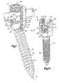
- FIG. 1is a perspective view of an apparatus constructed in accordance with a first embodiment of the present invention with portions removed for clarity;
- FIG. 1Ais another perspective view of the apparatus of FIG. 1 with parts removed for clarity;
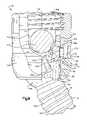
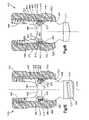
- FIG. 2is a sectional view of the apparatus of FIG. 1 ;
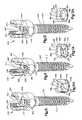
- FIG. 3is a part sectional view of the apparatus of FIG. 1 ;
- FIG. 4is an enlarged sectional view of a portion of the apparatus of FIG. 1 ;
- FIG. 5is a plan view of a spring member of the apparatus of FIG. 1 ;
- FIG. 6is a side view of the spring member of FIG. 5 ;
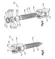
- FIG. 7is a perspective view of an apparatus constructed in accordance with another embodiment of the present invention with portions removed for clarity;
- FIG. 8is a part sectional view of the apparatus of FIG. 7 ;
- FIG. 9is an enlarged part sectional view of a portion of the apparatus of FIG. 7 ;
- FIG. 10is a perspective view of an apparatus constructed in accordance with another embodiment of the present invention with portions removed for clarity;
- FIG. 10Ais a perspective view of a spacer of the apparatus of FIG. 10 ;
- FIG. 11is a perspective view of an apparatus constructed in accordance with another embodiment of the present invention with portions removed for clarity;
- FIG. 11Ais a perspective view of a spacer of the apparatus of FIG. 11 ;
- FIG. 12is a perspective view of an apparatus constructed in accordance with another embodiment of the present invention with portions removed for clarity;
- FIG. 12Ais a perspective view of a spacer of the apparatus of FIG. 12 ;
- FIG. 13is a perspective view of an apparatus constructed in accordance with another embodiment of the present invention with portions removed for clarity;
- FIG. 14is an exploded view of the apparatus of FIG. 13 ;
- FIG. 15is a sectional view of the apparatus of FIG. 13 ;
- FIG. 16is a sectional view of an apparatus constructed in accordance with another embodiment of the present invention with portions removed for clarity;
- FIG. 17is an exploded view of an apparatus constructed in accordance with another embodiment of the present invention.
- FIG. 18is a sectional view of the apparatus of FIG. 17 ;
- FIG. 19is a sectional view of an apparatus constructed in accordance with another embodiment of the present invention.
- FIG. 20is a sectional view of an apparatus constructed in accordance with another embodiment of the present invention.
- FIG. 21is an enlarged sectional view of a portion of the apparatus of FIG. 20 .
- FIGS. 1–4illustrate an apparatus 10 constructed according to a first embodiment of the present invention.
- the apparatus 10includes a surgically implantable longitudinal member or rod 12 for maintaining bone portions, such as vertebrae of a spinal column, in a desired spatial relationship.
- the member 12is connected with vertebrae of the spinal column by fasteners 16 .
- the rod 12is made of a suitable biocompatible material and has a length which is at least sufficient to enable the rod to span at least two vertebrae.
- the length of the rod 12 in any particular installationwill depend upon the condition to be corrected and the number of vertebrae to be held in a desired spatial relationship relative to each other by the rod.
- the rod 12( FIGS. 1–3 ) is connected to a respective vertebra by the fastener 16 made of a suitable biocompatible material.
- the fastener 16has a longitudinal axis 18 and a threaded end portion 22 having a course thread convolution 24 which engages the vertebra.
- a second end portion 26 of the fastener 16is provided with a first part spherical surface 28 .
- the second end portion 26 of the fastener 16also includes a second part spherical surface 30 having a diameter less than a diameter of the first part spherical surface 28 .
- a radially extending shoulder 31extends between the part spherical surfaces 28 and 30 .
- a recess 32( FIG. 2 ) is provided on the end portion 26 of the fastener 16 .
- the recess 32receives a tool (not shown) that applies torque to the fastener 16 to turn the thread convolution 24 into the vertebra.
- the fastener 16( FIGS. 1–4 ) extends into a housing 40 that interconnects the rod 12 and the fastener 16 .
- the housing 40( FIG. 2 ) has a first passage 42 through which the rod 12 extends.
- the housing 40has a second passage 44 with a longitudinal axis 46 that extends transverse to the first passage 42 .
- the fastener 16extends through an opening 50 in the housing 40 and into the second passage 44 .
- the first part spherical surface 28 of the fastener 16engages a concave part spherical surface 52 of the housing 40 . Accordingly, the fastener 16 is universally pivotable relative to the housing 40 so that the longitudinal axis 18 of the fastener 16 is positionable in any one of a plurality of angular positions relative to the longitudinal axis 46 of the passage 44 .
- a spacer 60is housed in the second passage 44 of the housing 40 .
- the spacer 60( FIGS. 2–4 ) has a concave part spherical surface 62 that engages the part spherical surface 30 of the fastener 16 .
- the shoulder 31 on the fastener 16is engageable with the spacer 60 to limit the relative movement between the fastener and the housing 40 .
- the spacer 60also has a concave part cylindrical surface 64 that engages the rod 12 .
- the spacer 60has an opening 66 through which the tool (not shown) extends to engage the recess 32 in the fastener 16 . The tool extends through the opening 66 to apply torque to the fastener 16 and connect the fastener to the vertebra.
- the spacer 60includes two tabs 67 ( FIGS. 1 , 1 A, and 2 ) that are engageable with the housing 40 .
- the tabs 67engage surfaces of the housing 40 that define the passage 42 to restrict rotation of the spacer 60 within the housing 40 .
- the width of the tabs 67is selected as smaller than the width of the passage 42 to permit the spacer 60 to rotate slightly (preferably at least 10° and less than 30°) relative to the housing 40 when the rod 12 is disengaged from the spacer, but prevent sufficient rotation to completely move the concave portion 64 of the spacer outside of passage 42 .
- the tabs 67are spaced from the surfaces of the housing 40 that define the passage 42 when the rod 12 is disengaged from the spacer 60 to permit axial movement of the spacer relative to the housing.
- the tabs 67may be spaced from the surfaces of the housing 40 that define the passage 42 when the rod 12 is in engagement with the spacer 60 , as seen in FIG. 2 .
- the spacer 60( FIG. 4 ) has a circumferential groove 68 for receiving a compressible positioning member such as a spring member 70 .
- the groove 68is defined by an axially extending cylindrical surface 71 .
- An upper surface 72extends radially outward from the cylindrical surface 71 .
- a lower surface 74extends radially outward from the cylindrical surface 71 and generally parallel to the upper surface 72 .
- the housing 40includes a circumferential groove 76 for receiving the spring member 70 so that the spring member extends from the groove 68 in the spacer 60 to the groove in the housing.
- the groove 76is defined by an axially extending cylindrical surface 78 .
- An upper surface 80extends radially inward from the cylindrical surface 78 .
- a lower surface 82extends radially inward from the cylindrical surface 78 and generally parallel to the upper surface 80 .
- the spring member 70( FIGS. 5 and 6 ) is a ring having a gap 82 . It is contemplated that the spring member 70 may be any desired spring member, such as a coil spring.
- the gap 82permits the spring member 70 to radially contract and expand.
- the spring member 70has an arched shape, as viewed in FIG. 6 , when the spring member 70 is disengaged from the spacer 60 and the housing 40 .
- the spring member 70engages the lower surface 74 on the spacer 60 and the upper surface 80 on the housing 40 .
- the spring member 70applies an axial force to the spacer 60 to partially or completely restrict relative movement between the fastener 16 and the housing 40 when the rod 12 is disengaged from the spacer and the spacer engages the fastener (the phrase, “completely restrict” as used herein means that there is essentially no relative movement, and the phrase “partially restrict” means that movement is inhibited but that some movement is possible).
- the spring member 70urges the spacer 60 axially toward the fastener 16 and the part spherical surface 52 of the housing 40 against the part spherical surface 28 of the fastener.
- the part spherical surface 62 of the spacer 60frictionally engages the part spherical surface 30 of the fastener 16 and the part spherical surface 28 of the fastener frictionally engages the part spherical surface 52 of the housing 40 .
- the fastener 16 and the housing 40are manually movable relative to each other by a surgeon when the rod 12 is disengaged from the spacer 60 and the spring member 70 applies the axial force.
- the force applied by the spring member 70may be overcome by the surgeon to move the housing 40 relative to the fastener 16 .
- the housing 40can be positioned relative to the fastener 16 and held in position relative to the fastener by the spring member 70 without the rod 12 engaging the spacer 60 .
- any compressible membercould be used to apply the force to the fastener 16 to prevent relative movement between the fastener and the housing 40 when the rod 12 is disengaged from the spacer 60 .
- the spacer 60has four axially extending slots 86 , one of which is shown in FIG. 1 .
- the slots 86intersect the groove 68 .
- a tool(not shown) has prongs that extend through the slots 86 and into engagement with the spring member 70 .
- the toolgrasps the spacer 60 and the spring member 70 for inserting the spacer and the spring member into the housing 40 .
- the prongs of the toolengage the spring member 70 to radially contract the spring member into the groove 68 in the spacer 60 .
- the prongshold the spring member 70 in the radially contracted condition in the groove 68 while the spacer 60 and spring member are being inserted into the housing 40 .
- the spacer 60engages the fastener 16 , the prongs are removed from the slots 86 and the spring member 70 radially expands into the groove 71 in the housing 40 .
- the spacer 60is described as having four slots 86 , the spacer could have any number of slots and the tool would have the same number of prongs as the spacer has slots.
- a clamping mechanism or set screw 90threadably engages the housing 40 .
- the set screw 90 and the housing 40have a German standard DIN513 buttress thread. It is contemplated that the set screw 90 and the housing 40 could have any desired thread formation.
- the set screw 90engages and applies a force to the rod 12 to press the rod against the spacer 60 and the spacer against the fastener 16 .
- the set screw 90clamps the rod 12 , the spacer 60 , and the housing 40 to the fastener 16 to prevent movement of the fastener relative to the housing.
- the force applied by the set screw 90cannot be overcome by the surgeon to move the housing 40 relative to the fastener 16 .
- the apparatus 10is assembled by inserting the fastener 16 through the opening 50 in the housing 40 so that the part spherical surface 28 of the fastener engages the part spherical surface 52 of the housing.
- the spacer 60 and the spring member 70are inserted into the housing 40 by radially compressing the spring member into the groove 68 in the spacer.
- the spacer 60 and the spring member 70are inserted into the second passage 44 until the part spherical surface 62 of the spacer engages the part spherical surface 30 of the fastener 16 .
- the spring member 70is released and expands radially into the groove 76 in the housing 40 .
- a toolis inserted through the opening 66 in the spacer 60 and into the recess 32 in the fastener 16 .
- Torqueis applied to the fastener 16 to turn the thread convolution 24 into the vertebra.
- the housing 40can be positioned relative to the fastener.
- the spring member 70maintains the position of the housing 40 relative to the fastener 16 while the rod 12 is disengaged from the spacer 60 .
- the rod 12is placed into the passage 42 and in engagement with the spacer 60 .
- the set screw 90is threaded into the housing 40 and into engagement with the rod 12 .
- the set screw 90clamps the rod 12 , the spacer 60 , and the housing 40 to the fastener 16 to prevent movement of the fastener relative to the housing.
- the fastener 16may be connected to the vertebra prior to the spacer 60 and the spring member 70 being inserted into the housing 40 .
- FIGS. 7–9illustrate an apparatus 110 constructed according to another embodiment of the present invention.
- the apparatus 110includes a surgically implantable longitudinal member or rod 112 for maintaining bone portions, such as vertebrae of a spinal column, in a desired spatial relationship.
- the rod 112is connected with vertebrae of the spinal column by fasteners 116 .
- the rod 112is made of a suitable biocompatible material and has a length which is at least sufficient to enable the rod to span at least two vertebrae.
- the length of the rod 112 in any particular installationwill depend upon the condition to be corrected and the number of vertebrae to be held in a desired spatial relationship relative to each other by the rod.
- the rod 112is connected to a respective vertebra by the fastener 116 made of a suitable biocompatible material.
- the fastener 116has a longitudinal axis 118 and a threaded end portion 122 having a course thread convolution 124 which engages the vertebra.
- a second end portion 126 ( FIGS. 8–9 ) of the fastener 116is provided with a first part spherical surface 128 .
- the second end portion 126 of the fastener 116also includes a second part spherical surface 130 having a diameter less than a diameter of the first part spherical surface 128 .
- a radially extending shoulder 131extends between the part spherical surfaces 128 and 130 .
- a recess 132( FIGS. 8–9 ) is provided on the end portion 126 of the fastener 116 .
- the recess 132receives a tool (not shown) that applies torque to the fastener 116 to turn the thread convolution 124 into the vertebra.
- the fastener 116( FIGS. 7–9 ) extends into a housing 140 that interconnects the rod 112 and the fastener 116 .
- the housing 140has a first passage 142 through which the rod 112 extends.
- the housing 140has a second passage 144 with a longitudinal axis 146 that extends transverse to the first passage 142 .
- the fastener 116extends through an opening 150 in the housing 140 and into the second passage 144 .
- the first part spherical surface 128 of the fastener 116engages a concave part spherical surface 152 of the housing 140 .
- the fastener 116is universally pivotable relative to the housing 140 so that the longitudinal axis 118 of the fastener 116 is positionable in any one of a plurality of angular positions relative to the longitudinal axis 146 of the passage 144 .
- a spacer 160is received in the second passage 144 of the housing 140 .
- the spacer 160( FIGS. 8–9 ) has a concave part spherical surface 162 that engages the part spherical surface 130 of the fastener 116 .
- the spacer 160also has a concave part cylindrical surface 164 that engages the rod 112 .
- the spacer 160has an opening 166 through which the tool (not shown) extends to engage the recess 132 in the fastener 116 . The tool extends through the opening 166 to apply torque to the fastener 116 and connect the fastener to the vertebra.
- the spacer 160has a pair of axially extending grooves 168 , one of which is shown in FIGS. 7–9 .
- the grooves 168are located on diametrically opposite sides of the spacer 160 .
- a pair of positioning members or pin members 170extend transverse to the longitudinal axis 146 of the passage 144 and through the housing 140 into the grooves 168 and into engagement with the spacer 160 .
- the pin members 170retain the spacer 160 and the fastener 116 in the housing 140 .
- the pin members 170also restrict rotation of the spacer 160 relative to the housing 140 .
- the spacer 160could have only one groove and only one pin member could extend into the groove, or any number of grooves and pins could be used.
- the pin members 170are identical and, therefore, only one pin member will be described in detail.
- the pin member 170has a first cylindrical end portion 172 that extends into the groove 168 and engages the spacer 160 .
- the end portion 172 of the pin member 170has a frustoconical or tapered surface 173 .
- the tapered surface 173engages a lower axial edge 175 that defines the groove 168 as the pin member 170 is being inserted through the housing 140 to urge the spacer axially toward the fastener 116 .
- the pin member 170urges the spacer 160 into frictional engagement with the fastener 116 and the fastener into frictional engagement with the housing 140 . It is contemplated that the pin member 170 may not urge the spacer 160 axially toward the fastener 116 and only retain the spacer and the fastener in the housing 140 .
- a second cylindrical end portion or head 174 of the pin member 170is located in a cylindrical opening 176 in the housing 140 .
- the head 174has a diameter greater than a diameter of the end portion 172 .
- the pin member 170( FIG. 9 ) has a shoulder surface 177 extending perpendicular to the axis of the pin member 170 on the head 174 .
- the shoulder surface 177engages the housing 140 to limit the distance that the pin member 170 extends into the housing 140 .
- the head 174 of the pin member 170has a conical recess 178 ( FIG. 7 ) for receiving a tool (not shown), such as a center punch, to deform the head 174 into engagement with the housing 140 .
- the opening 176 ( FIG. 9 ) in the housing 140has a radially outer portion 180 with a diameter slightly smaller than a diameter of a radially central portion 182 of the opening.
- the head 174 of the pin member 170is received in the radially central portion 182 of the opening 176 .
- the material of the head 174is deformed into tight engagement with the material of the housing defining the central portion 182 of the opening 176 so that the diameter of the head is larger than the diameter of the radially outer portion 180 of the opening 176 .
- the pin member 170is fixedly connected to the housing 140 .
- the pin member 170is described as being deformed into engagement with the housing 140 , it is contemplated that the pin member could be press-fit into the housing or otherwise suitably fixed in the housing.
- the pin members 170engage the housing 140 and the spacer 160 to retain the spacer and the fastener in the housing 140 .
- the pin members 170also apply an axial force to the spacer 160 to prevent relative movement between the fastener 116 and the housing 140 when the rod 112 is disengaged from the spacer and the spacer engages the fastener.
- the pin members 170hold the part spherical surface 162 of the spacer 160 in frictional engagement with the part spherical surface 130 of the fastener 116 and the part spherical surface 128 of the fastener in frictional engagement with the part spherical surface 152 of the housing 140 .
- the frictional engagementsare effective to maintain the housing 140 and the fastener 116 in position when the rod 112 is disengaged from the spacer.
- the fastener 116 and the housing 140are manually movable relative to each other by a surgeon manually overcoming the frictional engagements when the rod 112 is disengaged from the spacer 160 and the pin members 170 engage the spacer.
- the housing 140can be positioned relative to the fastener 116 and held in position relative to the fastener by the pin members 170 without the rod 112 engaging the spacer 160 .
- the spacer 160 and the fastener 116are retained in the housing 140 by the pin members 170 and with the rod 112 disengaged from the spacer.
- a clamping mechanism or set screw 190threadably engages the housing 140 .
- the set screw 190 and the housing 140have a German standard DIN513 buttress thread. It is contemplated that the housing 140 and the set screw 190 could have any desired thread formation.
- the set screw 190engages the rod 112 to press the rod against the spacer 160 and the spacer against the fastener 116 .
- the set screw 190clamps the rod 112 , the spacer 160 , and the housing 140 to the fastener 116 to prevent movement of the fastener relative to the housing.
- the apparatus 110is assembled by inserting the fastener 116 through the opening 150 in the housing 140 so that the part spherical surface 128 of the fastener engages the part spherical surface 152 of the housing.
- the spacer 160is inserted into the second passage 144 of the housing 140 until the part spherical surface 162 of the spacer engages the part spherical surface 130 of the fastener 116 .
- the pin members 170are inserted into the openings 176 in the housing 140 until the end portions 172 extend into the grooves 168 in the spacer 160 and engage the spacer.
- the tapered surfaces 173 of the pin members 170engage the edges 175 to urge the spacer 160 axially toward the fastener 116 .
- the heads 174 of the pins 170are deformed to fixedly connect the pins to the housing 140 .
- a toolis inserted through the opening 166 in the spacer 160 and into the recess 132 in the fastener 116 .
- Torqueis applied to the fastener 116 to turn the thread convolution 124 into the vertebra.
- the housing 140can be positioned relative to the fastener.
- the pin members 170 and the above described frictional engagementsmaintain the position of the housing 140 relative to the fastener 116 while the rod 112 is disengaged from the spacer 160 .
- the rod 112is placed into the passage 142 and in engagement with the spacer 160 .
- the set screw 190is threaded into the housing 140 and into engagement with the rod 112 .
- the set screw 190clamps the rod 112 , the spacer 160 , and the housing 140 to the fastener 116 to prevent movement of the fastener relative to the housing.
- the pin members 170could be inserted into the housing 140 prior to the spacer 160 being inserted into the housing. If the spacer 160 is inserted after the pin members 170 , the spacer would have L-shaped grooves with axially extending portions and circumferentially extending portions. The spacer 160 would be inserted into the housing 140 with the axially extending portions aligned with the pin members 170 until the pin members extend into the circumferentially extending portions. The spacer 160 would be rotated relative to the housing 140 until the pin members 170 are located in ends of the circumferentially extending portions of the grooves opposite from the axially extending portions.
- FIGS. 10 and 10AAn apparatus 210 constructed according to another embodiment of the present invention is illustrated in FIGS. 10 and 10A .
- the apparatus 210is substantially similar to the apparatus 10 illustrated in FIGS. 1–6 . Accordingly, the apparatus 210 will not be described in detail.
- the apparatus 210includes a fastener 216 ( FIG. 10 ) for connecting a surgically implantable longitudinal member or rod (not shown) to bone portions, such as vertebrae of a spinal column, to maintain the vertebrae in a desired spatial relationship.
- the rod and the fastener 216are identical to the rod 12 and the fastener 16 illustrated in FIGS. 1–4 . Accordingly, the rod and the fastener 216 will not be described in detail.
- the fastener 216extends into a housing 240 that interconnects the rod and the fastener.
- the housing 240is identical to the housing 40 illustrated in FIGS. 1–4 . Accordingly, the housing 240 will not be described in detail.
- a part spherical surface of the fastener 216engages a concave part spherical surface of the housing 240 so that the fastener is universally pivotable relative to the housing and an axis of the fastener is positionable in any one of a plurality of angular positions relative to an axis of a passage 244 of the housing.
- a spacer 260( FIGS. 10 and 10A ) is housed in the passage 244 of the housing 240 .
- the spacer 260has a concave part spherical surface 262 that engages a part spherical surface of the fastener 216 .
- the spacer 260also has a concave part cylindrical surface 264 that engages the rod when the surface 264 is aligned with a passage 242 in the housing 240 .
- the spacer 260has an opening 266 through which a tool (not shown) extends to engage a recess 232 in the fastener 216 . The tool extends through the opening 266 to apply torque to the fastener 216 and connect the fastener to the vertebra.
- the spacer 260is substantially similar to the spacer 60 illustrated in FIGS. 1–4 . However, the spacer 260 does not include tabs 67 .
- the spacer 260( FIG. 10A ) has a circumferential groove 268 for receiving a compressible positioning member such as a spring member (not shown).
- the housing 240includes a circumferential groove (not shown) for receiving the spring member so that the spring member extends from the groove 268 in the spacer 260 to the groove in the housing.
- the spring membermay be identical to the spring member 70 illustrated in FIGS. 1–6 , or may be a functionally equivalent compressible element.
- the spring memberWhen the spring member is received in the groove 268 in the spacer 260 and the groove in the housing 240 , the spring member applies an axial force to the spacer 260 to prevent relative movement between the fastener 216 and the housing 240 when the rod is disengaged from the spacer and the spacer engages the fastener.
- the spring memberurges the spacer 260 axially toward the fastener 216 so that the part spherical surface 262 of the spacer 260 frictionally engages a part spherical surface of the fastener 216 and another part spherical surface of the fastener frictionally engages the concave part spherical surface of the housing 240 .
- the fastener 216 and the housing 240are manually movable relative to each other by a surgeon when the rod is disengaged from the spacer 260 and the spring member applies the axial force.
- the force applied by the spring membermay be overcome by the surgeon to move the housing 240 relative to the fastener 216 . Accordingly, the housing 240 can be positioned relative to the fastener 216 and held in position relative to the fastener by the spring member without the rod engaging the spacer 260 .
- the spacer 260has four axially extending slots 286 .
- the slots 286intersect the groove 268 .
- a tool(not shown) has four prongs that extend through the slots 286 and into engagement with the spring member. The tool grasps the spacer 260 and the spring member for inserting the spacer and the spring member into the housing 240 . The prongs of the tool engage the spring member to radially contract the spring member into the groove 268 in the spacer 260 . The prongs hold the spring member in the radially contracted condition in the groove 268 while the spacer 260 and spring member are being inserted into the housing 240 .
- the spacer 260engages the fastener 216 , the prongs are removed from the slots 286 and the spring member radially expands into the groove in the housing 240 .
- the spacer 260is described as having four slots 286 , the spacer could have any number of slots and the tool would have the same number of prongs as the spacer has slots.
- a clamping mechanism or set screwthreadably engages the housing 240 .
- the clamping mechanismis identical to the clamping mechanism 90 illustrated in FIGS. 1–4 .
- the set screwengages and applies a force to the rod to press the rod against the spacer 260 and the spacer against the fastener 216 .
- the set screwclamps the rod, the spacer 260 , and the housing 240 to the fastener 216 to prevent movement of the fastener relative to the housing.
- the force applied by the set screwcannot be overcome by the surgeon to move the housing 240 relative to the fastener 216 .
- the apparatus 210is assembled by inserting the fastener 216 through an opening in the housing 240 so that a part spherical surface of the fastener engages the concave part spherical surface of the housing.
- the spacer 260 and the spring memberare inserted into the housing 240 by radially compressing the spring member into the groove 268 in the spacer.
- the spacer 260 and the spring memberare inserted into the passage 244 in the housing 240 until the part spherical surface 262 of the spacer engages a part spherical surface of the fastener 216 .
- the spring memberis released and expands radially into the groove in the housing 240 .
- a toolis inserted through the opening 266 in the spacer 260 and into the recess 232 in the fastener 216 .
- Torqueis applied to the fastener 216 to turn a thread convolution 224 into the vertebra.
- the housing 240can be positioned relative to the fastener.
- the spring membermaintains the position of the housing 240 relative to the fastener 216 while the rod is disengaged from the spacer 260 .
- the spacer 260is rotated relative to the housing 240 to align the part cylindrical surface 264 of the spacer with the passage 242 in the housing 240 .
- the rodis placed into the passage 242 in the housing 240 and in engagement with the spacer 260 .
- the set screwis threaded into the housing 240 and into engagement with the rod.
- the set screwclamps the rod, the spacer 260 , and the housing 240 to the fastener 216 to prevent movement of the fastener relative to the housing.
- the fastener 216may be connected to the vertebra prior to the spacer 260 and the spring member being inserted into the housing 240 .
- FIGS. 11 and 11AAn apparatus 310 constructed according to another embodiment of the present invention is illustrated in FIGS. 11 and 11A .
- the apparatus 310is substantially similar to the apparatus 10 illustrated in FIGS. 1–6 . Accordingly, the apparatus 310 will not be described in detail.
- the apparatus 310includes a fastener 316 ( FIG. 11 ) for connecting a surgically implantable longitudinal member or rod (not shown) to bone portions, such as vertebrae of a spinal column, to maintain the vertebrae in a desired spatial relationship.
- the rod and the fastener 316are identical to the rod 12 and the fastener 16 illustrated in FIGS. 1–4 . Accordingly, the rod and the fastener 316 will not be described in detail.
- the fastener 316extends into a housing 340 that interconnects the rod and the fastener.
- the housing 340is identical to the housing 40 illustrated in FIGS. 1–4 . Accordingly, the housing 340 will not be described in detail.
- a part spherical surface of the fastener 316engages a concave part spherical surface of the housing 340 so that the fastener is universally pivotable relative to the housing and an axis of the fastener is positionable in any one of a plurality of angular positions relative to an axis of a passage 344 of the housing.
- a spacer 360( FIGS. 11 and 11A ) is housed in the passage 344 of the housing 340 .
- the spacer 360has a concave part spherical surface 362 that engages a part spherical surface of the fastener 316 .
- the spacer 360has a pair of diametrically opposed concave part cylindrical surfaces 364 .
- the surfaces 364engage the rod when the surfaces 364 are aligned with a passage 342 in the housing 340 through which the rod extends.
- the spacer 360also includes a pair of diametrically opposed concave part cylindrical surfaces 365 .
- the surfaces 365engage the rod when the surfaces 365 are aligned with the passage 342 .
- the surfaces 364are located 90° from the surfaces 365 .
- the spacer 360has a plurality of rotational positions relative to the housing 340 for receiving the longitudinal member.
- the spacer 360is shown as having two sets of diametrically opposed cylindrical surfaces 364 and 365 , it is contemplated that the spacer may have any number of sets of cylindrical surfaces.
- the spacer 360has an opening 366 through which a tool (not shown) extends to engage a recess 332 in the fastener 316 . The tool extends through the opening 366 to apply torque to the fastener 316 and to connect the fastener to the vertebra.
- the spacer 360( FIG. 11A ) has a circumferential groove 368 for receiving a compressible member such as a spring member (not shown).
- the housing 340includes a circumferential groove (not shown) for receiving the spring member so that the spring member extends from the groove 368 in the spacer 360 to the groove in the housing.
- the spring memberis identical to the spring member 70 illustrated in FIGS. 1–6 .
- the spring memberWhen the spring member is received in the groove 368 in the spacer 360 and the groove in the housing 340 , the spring member applies an axial force to the spacer 360 to prevent relative movement between the fastener 316 and the housing 340 when the rod is disengaged from the spacer and the spacer engages the fastener.
- the spring memberurges the spacer 360 axially toward the fastener 316 so that the part spherical surface 362 of the spacer 360 frictionally engages a part spherical surface of the fastener 316 and another part spherical surface of the fastener frictionally engages the concave part spherical surface of the housing 340 .
- the fastener 316 and the housing 340are manually movable relative to each other by a surgeon when the rod is disengaged from the spacer 360 and the spring member applies the axial force.
- the force applied by the spring membermay be overcome by the surgeon to move the housing 340 relative to the fastener 316 . Accordingly, the housing 340 can be positioned relative to the fastener 316 and held in position relative to the fastener by the spring member without the rod engaging the spacer 360 .
- the spacer 360has four axially extending slots 386 .
- the slots 386intersect the groove 368 .
- a tool(not shown) has four prongs that extend through the slots 386 and into engagement with the spring member.
- the toolgrasps the spacer 360 and the spring member for inserting the spacer and the spring member into the housing 340 .
- the prongs of the toolengage the spring member to radially contract the spring member into the groove 368 in the spacer 360 .
- the prongshold the spring member in the radially contracted condition in the groove 368 while the spacer 360 and spring member are being inserted into the housing 340 .
- the spacer 360engages the fastener 316 , the prongs are removed from the slots 386 and the spring member radially expands into the groove in the housing 340 .
- the spacer 360is described as having four slots 386 , the spacer could have any number of slots and the tool would have the same number of prongs as the spacer has slots.
- a clamping mechanism or set screwthreadably engages the housing 340 .
- the claming mechanismis identical to the clamping mechanism 90 illustrated in FIGS. 1–4 .
- the set screwengages and applies a force to the rod to press the rod against the spacer 360 and the spacer against the fastener 316 .
- the set screwclamps the rod, the spacer 360 , and the housing 340 to the fastener 316 to prevent movement of the fastener relative to the housing.
- the force applied by the set screwcannot be overcome by the surgeon to move the housing 340 relative to the fastener 316 .
- the apparatus 310is assembled by inserting the fastener 316 through an opening in the housing 340 so that a part spherical surface of the fastener engages the concave part spherical surface of the housing.
- the spacer 360 and the spring memberare inserted into the housing 340 by radially compressing the spring member into the groove 368 in the spacer.
- the spacer 360 and the spring memberare inserted into the passage 344 in the housing 340 until the part spherical surface 362 of the spacer engages a part spherical surface of the fastener 316 .
- the spring memberis released and expands radially into the groove in the housing 340 .
- a toolis inserted through the opening 366 in the spacer 360 and into the recess 332 in the fastener 316 .
- Torqueis applied to the fastener 316 to turn a thread convolution 324 into the vertebra.
- the housing 340can be positioned relative to the fastener.
- the spring membermaintains the position of the housing 340 relative to the fastener 316 while the rod is disengaged from the spacer 360 .
- the spacer 360is rotated relative to the housing 340 to align part cylindrical surfaces 364 or part cylindrical surfaces 365 with the passage 342 in the housing 340 .
- the rodis placed into the passage 342 in The housing 340 and in engagement with the spacer 360 .
- the set screwis threaded into the housing 340 and into engagement with the rod.
- the set screwclamps the rod, the spacer 360 , and the housing 340 to the fastener 316 to prevent movement of the fastener relative to the housing.
- the fastener 316may be connected to the vertebra prior to the spacer 360 and the spring member being inserted into the housing 340 .
- FIGS. 12 and 12AAn apparatus 410 constructed according to another embodiment of the present invention is illustrated in FIGS. 12 and 12A .
- the apparatus 410is substantially similar to the apparatus 10 illustrated in FIGS. 1–6 . Accordingly, the apparatus 410 will not be described in detail.
- the apparatus 410includes a fastener 416 ( FIG. 12 ) for connecting a surgically implantable longitudinal member or rod (not shown) to bone portions, such as vertebrae of a spinal column, to maintain the vertebrae in a desired spatial relationship.
- the rod and the fastener 416are identical to the rod 12 and the fastener 16 illustrated in FIGS. 1–4 . Accordingly, the rod and the fastener 416 will not be described in detail.
- the fastener 416extends into a housing 440 that interconnects the rod and the fastener.
- the housing 440is identical to the housing illustrated in FIGS. 1–4 . Accordingly, the housing 440 will not be described in detail.
- a part spherical surface of the fastener 416engages a concave part spherical surface of the housing 440 so that the fastener is universally pivotable relative to the housing and an axis of the fastener is positionable in any one of a plurality of angular positions relative to an axis of a passage 444 of the housing.
- a spacer 460( FIGS. 12 and 12A ) is housed in the passage 444 of the housing 440 .
- the spacer 460has a concave part spherical surface 462 that engages a part spherical surface of the fastener 416 .
- the spacer 460includes a planar upper surface 464 that engages the rod.
- the spacer 460also has an opening 466 through which a tool (not shown) extends to engage a recess 432 in the fastener 416 . The tool extends through the opening 466 to apply torque to the fastener 416 and connect the fastener to the vertebra.
- the spacer 460( FIG. 12A ) has a circumferential groove 468 for receiving a compressible member such as a spring member (not shown).
- the housing 440includes a circumferential groove (not shown) for receiving the spring member so that the spring member extends from the groove 468 in the spacer 460 to the groove in the housing.
- the spring memberis identical to the spring member 70 illustrated in FIGS. 1–6 .
- the spring memberWhen the spring member is received in the groove 468 in the spacer 460 and the groove in the housing 440 , the spring member applies an axial force to the spacer 460 to prevent relative movement between the fastener 416 and the housing 440 when the rod is disengaged from the spacer and the spacer engages the fastener.
- the spring memberurges the spacer 460 axially toward the fastener 416 so that the part spherical surface 462 of the spacer frictionally engages a part spherical surface of the fastener and another part spherical surface of the fastener frictionally engages the concave part spherical surface of the housing 440 .
- the fastener 416 and the housing 440are manually movable relative to each other by a surgeon when the rod is disengaged from the spacer 460 and the spring member applies the axial force.
- the force applied by the spring membermay be overcome by the surgeon to move the housing 440 relative to the fastener 416 . Accordingly, the housing 440 can be positioned relative to the fastener 416 and held in position relative to the fastener by the spring member without the rod engaging the spacer 460 .
- the spacer 460has four axially extending slots 486 .
- the slots 486intersect the groove 468 .
- a tool(not shown) has four prongs that extend through the slots 486 and into engagement with the spring member. The tool grasps the spacer 460 and the spring member for inserting the spacer and the spring member into the housing 440 . The prongs of the tool engage the spring member to radially contract the spring member into the groove 468 in the spacer 460 . The prongs hold the spring member in the radially contracted condition in the groove 468 while the spacer 460 and spring member are being inserted into the housing 440 .
- the spacer 460engages the fastener 416 , the prongs are removed from the slots 486 and the spring member radially expands into the groove in the housing 440 .
- the spacer 460is described as having four slots 486 , the spacer could have any number of slots and the tool would have the same number of prongs as the spacer has slots.
- a clamping mechanism or set screwthreadably engages the housing 440 .
- the clamping mechanismis identical to the clamping mechanism 90 illustrated in FIGS. 1–4 .
- the set screwengages and applies a force to the rod to press the rod against the spacer 460 and the spacer against the fastener 416 .
- the set screwclamps the rod, the spacer 460 , and the housing 440 to the fastener 416 to prevent movement of the fastener relative to the housing.
- the force applied by the set screwcannot be overcome by the surgeon to move the housing 440 relative to the fastener 416 .
- the apparatus 410is assembled by inserting the fastener 416 through the opening in the housing 440 so that a part spherical surface of the fastener engages a part spherical surface of the housing.
- the spacer 460 and the spring memberare inserted into the housing 440 by radially compressing the spring member into the groove 468 in the spacer.
- the spacer 460 and the spring memberare inserted into the passage 444 in the housing 440 until the part spherical surface 462 of the spacer engages a part spherical surface of the fastener 416 .
- the spring memberis released and expands radially into the groove in the housing 440 .
- a toolis inserted through the opening 466 in the spacer 460 and into the recess 432 in the fastener 416 .
- Torqueis applied to the fastener 416 to turn a thread convolution 424 into the vertebra.
- the housing 440can be positioned relative to the fastener.
- the spring membermaintains the position of the housing 440 relative to the fastener 416 while the rod is disengaged from the spacer 460 .
- the rodis placed into a passage 442 in the housing 440 and in engagement with the surface 464 of the spacer 460 .
- the set screwis threaded into the housing 440 and into engagement with the rod.
- the set screwclamps the rod, the spacer 460 , and the housing 440 to the fastener 416 to prevent movement of the fastener relative to the housing.
- the fastener 416may be connected to the vertebra prior to the spacer 460 and the spring member being inserted into the housing 440 .
- FIGS. 13–15An apparatus 510 constructed according to another embodiment of the present invention is illustrated in FIGS. 13–15 .
- the apparatus 510includes a fastener 516 for connecting a surgically implantable longitudinal member or rod (not shown) to bone portions, such as vertebrae of a spinal column, to maintain the vertebrae in a desired spatial relationship.
- the fastener 516has a longitudinal axis 518 and a threaded end portion 522 having a course thread convolution 524 which engages the vertebra.
- a second end portion 526 of the fastener 516is provided with a spherical surface 528 .
- a recess 532is provided on the end portion 526 of the fastener 516 .
- the recess 532receives a tool (not shown) that applies torque to the fastener 516 to turn the thread convolution 524 into the vertebra.
- the fastener 516extends into a housing 540 that interconnects the rod and the fastener 516 .
- the housing 540has a first passage 542 through which the rod extends.
- the housing 540has a second passage 544 with a longitudinal axis that extends transverse to the passage 542 .
- the fastener 516extends through an opening 550 in the housing 540 and into the second passage 544 .
- the spherical surface 528 of the fastener 516engages a concave part spherical surface 552 of the housing 540 .
- the fastener 516is universally pivotable relative to the housing 540 so that the longitudinal axis 518 of the fastener 516 is positionable in any one of a plurality of angular positions relative to the longitudinal axis of the passage 544 .
- a spacer 560is housed in the second passage 544 of the housing 540 .
- the spacer 560( FIG. 15 ) has a concave part spherical surface 562 that engages the spherical surface 528 of the fastener 516 .
- the spacer 560( FIG. 14 ) has diametrically opposed concave part cylindrical surfaces 564 .
- the surfaces 564engage the rod when the surfaces 564 are aligned with the passage 542 in the housing 540 .
- the spacer 560also includes diametrically opposed concave part cylindrical surfaces 565 .
- the surfaces 565engage the rod when the surfaces 565 are aligned with the passage 542 .
- the surfaces 564are located at 90° relative to the surfaces 565 .
- the spacer 560has an opening 566 through which the tool (not shown) extends to engage the recess 532 in the fastener 516 .
- the toolextends through the opening 566 to apply torque to the fastener 516 and connect the fastener to the vertebra.
- the spacer 560( FIGS. 14–15 ) has a first radially outer cylindrical surface 567 with an outer diameter slightly smaller than the diameter of the passage 544 in the housing 540 .
- the spacer 560includes a second radially outer cylindrical surface 568 having a diameter smaller than the cylindrical surface 567 .
- a radially extending surface 569extends from the cylindrical surface 568 to the cylindrical surface 567 .
- a ring-shaped retaining or positioning member 570holds the spacer 560 in the housing 540 .
- the retaining member 570includes a plurality of spring members or leaf springs 572 extending from a retaining portion 574 .
- the spring members 572 and the retaining portion 574may be formed as a single, integral component.
- the spring members 572may be formed by spirally cutting the retaining member. It is contemplated that the spring members 572 could be formed as separate pieces that are attached to the retaining portion 574 .
- the retaining member 570may be made of any suitable biocompatible material such as an titanium-aluminum-vanadium alloy or a nickel-titanium alloy such as super-elastic Nitinol.
- the spring members 572engage the radially extending surface 569 on the spacer 560 to apply an axial force to the spacer to prevent relative movement between the fastener 516 and the housing 540 when the rod is disengaged from the spacer and the spacer engages the fastener.
- the spring members 572urge the spacer 560 axially toward the fastener 516 and the part spherical surface 552 of the housing 540 against the spherical surface 528 of the fastener.
- the part spherical surface 562 of the spacer 560frictionally engages the spherical surface 528 of the fastener 516 and the spherical surface 528 of the fastener frictionally engages the part spherical surface 552 of the housing 540 .
- the fastener 516 and the housing 540are manually movable relative to each other by a surgeon when the rod is disengaged from the spacer 560 and the spring members 572 apply the axial force.
- the force applied by the spring members 572may be overcome by the surgeon to move the housing 540 relative to the fastener 516 . Accordingly, the housing 540 can be positioned relative to the fastener 516 and held in position relative to the fastener by the spring members 572 without the rod engaging the spacer 560 .
- the retaining portion 574 ( FIG. 15 ) of the retaining member 570has a radially inner cylindrical surface 576 with a diameter slightly larger than the outside diameter of the cylindrical surface 568 on the spacer 560 .
- the retaining portion 574 of the retaining member 570has a radially outer cylindrical surface 578 that engages the housing 540 .
- the retaining portion 574 of the retaining member 570is press-fit into the passage 544 in the housing 540 to fixedly connect the retaining member to the housing 540 .
- the spring members 572have an outer diameter that is smaller than the diameter of the passage 544 in the housing 540 . Accordingly, the spring members 572 can move relative to the housing 540 .
- the spacer 560can move axially relative to the housing 540 and the retaining portion 574 when the rod is disengaged from the spacer 560 .
- the amount of axial force applied by the spring members 572 to the spacer 560depends on the position of the retaining portion 574 relative to the housing 540 and the spacer 560 .
- the retaining portion 574may be press-fit into the housing 540 in any one of a plurality of axial positions relative to the housing. It is contemplated that the retaining portion 574 may be connected to the housing 540 in a desired manner. Accordingly, the amount of axial force applied by the spring members 572 to the spacer 560 may be adjusted to a desired force.
- the force applied by the spring members 572increases as the retaining portion 574 gets closer to the radial surface 569 on the spacer 560 .
- a clamping mechanism or set screwthreadably engages the housing 540 .
- the set screwengages and applies a force to the rod to press the rod against the spacer 560 and the spacer against the fastener 516 .
- the set screwclamps the rod, the spacer 560 , and the housing 540 to the fastener 516 to prevent movement of the fastener relative to the housing.
- the force applied by the set screwcannot be overcome by the surgeon to move the housing 540 relative to the fastener 516 .
- the apparatus 510is assembled by inserting the fastener 516 through the opening 550 in the housing 540 so that the spherical surface 528 of the fastener engages the part spherical surface 552 of the housing.
- the spacer 560is inserted into the housing 540 and into engagement with the fastener 516 .
- the retaining member 570is inserted into the second passage 544 until the spring members 572 engage the spacer 560 and the spring members apply the desired force to the spacer 560 .
- a toolis inserted through the opening 566 in the spacer 560 and into the recess 532 in the fastener 516 .
- Torqueis applied to the fastener 516 to turn the thread convolution 524 into the vertebra.
- the housing 540can be positioned relative to the fastener.
- the spring members 572maintain the position of the housing 540 relative to the fastener 516 while the rod is disengaged from the spacer 560 .
- the spacer 560is rotated relative to the housing 540 to align the surfaces 564 or 565 with the passage 542 in the housing.
- the rodis placed into the passage 542 and in engagement with the spacer 560 .
- the set screwis threaded into the housing 540 and into engagement with the rod.
- the set screwclamps the rod, the spacer 560 , and the housing 540 to the fastener 516 to prevent movement of the fastener relative to the housing.
- the fastener 516may be connected to the vertebra prior to the spacer 560 and the retaining member 570 being inserted into the housing 540 .
- FIG. 16An apparatus 610 constructed according to another embodiment of the present invention is illustrated in FIG. 16 .
- the apparatus 610is substantially similar to the apparatus 510 illustrated in FIGS. 13–15 . Accordingly, the apparatus 610 will not be described in detail.
- the apparatus 610includes a fastener 616 for connecting a surgically implantable longitudinal member or rod (not shown) to bone portions, such as vertebrae of a spinal column, to maintain the vertebrae in a desired spatial relationship.
- the fastener 616is identical to the fastener 516 illustrated in FIGS. 13–15 . Accordingly, the fastener 616 will not be described in detail.
- the fastener 616extends into a housing 640 that interconnects the rod and the fastener 616 .
- the housing 640has a first passage 642 through which the rod extends.
- the housing 640has a second passage 644 that extends transverse to the passage 642 .
- the passage 644is defined by a pair of first or upper part cylindrical surfaces 646 having a first diameter.
- the housing 640has a second or lower cylindrical surface 647 having a second diameter smaller than the first diameter.
- a tapered surface 648extends from the first cylindrical surfaces 646 to the second cylindrical surface 648 .
- the fastener 616extends through an opening 650 in the housing 640 and into the second passage 644 .
- a spherical surface 628 of the fastener 616engages a concave part spherical surface 652 of the housing 640 . Accordingly, the fastener 616 is universally pivotable relative to the housing 640 so that a longitudinal axis of the fastener 616 is positionable in any one of a plurality of angular positions relative to a longitudinal axis of the passage 644 .
- a spacer 660is housed in the second passage 644 of the housing 640 .
- the spacer 660is identical to the spacer 560 illustrated in FIGS. 13–14 . Accordingly, the spacer 660 will not be described in detail.
- a ring-shaped retaining member 670holds the spacer 660 in the housing 640 .
- the retaining member 670is identical to the retaining member 570 illustrated in FIGS. 14–15 . Accordingly, the retaining member 670 will not be described in detail.
- the retaining member 670includes spring members 672 .
- the spring members 672engage a radially extending surface 669 on the spacer 660 to apply an axial force to the spacer to prevent relative movement between the fastener 616 and the housing 640 when the rod is disengaged from the spacer and the spacer engages the fastener.
- the spring members 672urge the spacer 660 axially toward the fastener 616 and the part spherical surface 652 of the housing 640 against the spherical surface 628 of the fastener.
- a part spherical surface 662 of the spacer 660frictionally engages the spherical surface 628 of the fastener 616 and the spherical surface 628 of the fastener frictionally engages the part spherical surface 652 of the housing 640 .
- the fastener 616 and the housing 640are manually movable relative to each other by a surgeon when the rod is disengaged from the spacer 660 and the spring members 672 apply the axial force.
- the force applied by the spring members 672may be overcome by the surgeon to move the housing 640 relative to the fastener 616 . Accordingly, the housing 640 can be positioned relative to the fastener 616 and held in position relative to the fastener by the spring members 672 without the rod engaging the spacer 660 .
- a retaining portion 674 of the retaining member 670has a radially inner cylindrical surface 676 with a diameter slightly larger than the outside diameter of a radially outer cylindrical surface 668 on the spacer 660 .
- the retaining portion 674has a radially outer cylindrical surface 678 that engages the housing 640 .
- the outer cylindrical surface 678has a diameter which is slightly smaller than the diameter of the cylindrical surfaces 646 of the housing 640 and slightly larger than the diameter of the cylindrical surface 647 of the housing. Accordingly, the retaining member 670 is easily inserted into the housing 640 .
- the retaining portion 674engages the tapered surface 648 of the housing 640 .
- the retaining portion 674is then press-fit into engagement with the surface 647 of the housing 640 to fixedly connect the retaining member 670 to the housing.
- the spring members 672have an outer diameter that is smaller than the diameter of the cylindrical surface 647 of the housing 640 . Accordingly, the spring members 672 can move relative to the housing 640 .
- the spacer 660can move axially relative to the housing 640 and the retaining portion 674 when the rod is disengaged from the spacer 660 .
- the amount of axial force applied by the spring members 672 to the spacer 660depends on the position of the retaining portion 674 relative to the housing 640 and the spacer 660 .
- the retaining portion 674may be press-fit into the housing 640 in any one of a plurality of axial positions relative to the housing. Accordingly, the amount of axial force applied by the spring members 672 to the spacer 660 may be adjusted to a desired force.
- a clamping mechanism or set screwthreadably engages the housing 640 .
- the set screwengages and applies a force to the rod to press the rod against the spacer 660 and the spacer against the fastener 616 .
- the set screwclamps the rod, the spacer 660 , and the housing 640 to the fastener 616 to prevent movement of the fastener relative to the housing.
- the force applied by the set screwcannot be overcome by the surgeon to move the housing 640 relative to the fastener 616 .
- the apparatus 610is assembled by inserting the fastener 616 through the opening 650 in the housing 640 so that the spherical surface 628 of the fastener engages the part spherical surface 652 of the housing.
- the spacer 660is inserted into the housing 640 and into engagement with the fastener 616 .
- the retaining member 670is inserted into the second passage 644 until the retaining portion 674 engages the surface 647 of the housing and the spring members 672 engage the spacer 660 .
- the retaining member 670is inserted into the housing 640 so that the spring members 672 apply the desired force to the spacer 660 .
- a toolis inserted through an opening 666 in the spacer 660 and into a recess in the fastener 616 .
- Torqueis applied to the fastener 616 to thread the fastener into the vertebra.
- the housing 640can be positioned relative to the fastener.
- the spring members 672maintain the position of the housing 640 relative to the fastener 616 while the rod is disengaged from the spacer 660 .
- the spacer 660is rotated relative to the housing to align part cylindrical surfaces 664 or 665 with the passage 642 in the housing.
- the rodis placed into the passage 642 and in engagement with the spacer 660 .
- the set screwis threaded into the housing 640 and into engagement with the rod.
- the set screwclamps the rod, the spacer 660 , and the housing 640 to the fastener 616 to prevent movement of the fastener relative to the housing.
- the fastener 616may be connected to the vertebra prior to the spacer 660 and the retaining member 670 being inserted into the housing 640 .
- FIGS. 17–18An apparatus 710 constructed according to another embodiment of the present invention is illustrated in FIGS. 17–18 .
- the apparatus 710is substantially similar to the apparatus 610 illustrated in FIG. 16 . Accordingly, the apparatus 710 will not be described in detail.
- the apparatus 710includes a fastener 716 for connecting a surgically implantable longitudinal member or rod (not shown) to bone portions, such as vertebrae of a spinal column, to maintain the vertebrae in a desired spatial relationship.
- the fastener 716is identical to the fastener 616 illustrated in FIG. 16 . Accordingly, the fastener 716 will not be described in detail.
- the fastener 716extends into a housing 740 that interconnects the rod and the fastener 716 .
- the housing 740is identical to the housing 640 illustrated in FIG. 16 . Accordingly, the housing 740 will not be described in detail.
- a spherical surface 728 of the fastener 716engages a concave part spherical surface 752 of the housing 740 . Accordingly, the fastener 716 is universally pivotable relative to the housing 740 so that a longitudinal axis of the fastener 716 is positionable in any one of a plurality of angular positions relative to a longitudinal axis of a passage 744 of the housing 740 .
- a spacer 760is housed in the passage 744 of the housing 740 .
- the spacer 760is identical to the spacer 660 illustrated in FIG. 16 . Accordingly, the spacer 760 will not be described in detail.
- a ring-shaped retaining member 770holds the spacer 760 in the housing 740 .
- a Bellville washer or spring member 772engages the retainer member 770 and the spacer 760 . It is contemplated that the spring member 772 may have any desired shape.
- the spring member 772engages a radially extending surface 769 on the spacer 760 to apply an axial force to the spacer to prevent relative movement between the fastener 716 and the housing 740 when the rod is disengaged from the spacer and the spacer engages the fastener.
- the spring member 772urges the spacer 760 axially toward the fastener 716 and the part spherical surface 752 of the housing 740 against the spherical surface 728 of the fastener.
- the fastener 716 and the housing 740are manually movable relative to each other by a surgeon when the rod is disengaged from the spacer 760 and the spring member 772 applies the axial force.
- the force applied by the spring member 772may be overcome by the surgeon to move the housing 740 relative to the fastener 716 . Accordingly, the housing 740 can be positioned relative to the fastener 716 and held in position relative to the fastener by the spring member 772 without the rod engaging the spacer 760 .
- the retaining member 770has a radially inner cylindrical surface 776 with a diameter slightly larger than the outside diameter of a radially outer cylindrical surface 768 on the spacer 760 .
- the retaining member 770has a radially outer cylindrical surface 778 with a diameter slightly smaller than the diameter of cylindrical surfaces 746 of the housing 740 .
- the diameter of the outer cylindrical surface 778 of the retaining member 770is slightly smaller than the diameter of cylindrical surface 747 of the housing 740 . Accordingly, the retaining member 770 is easily inserted into the housing 740 .
- the retaining member 770engages a tapered surface 748 of the housing 740 .
- the retaining member 770is press-fit into the housing 740 in engagement with the surface 747 to fixedly connect the retaining member to the housing 740 .
- the spacer 760can move axially relative to the housing 740 and the retaining member 770 when the rod is disengaged from the spacer 760 .
- the amount of axial force applied by the spring member 772 to the spacer 760depends on the position of the retaining member 770 relative to the housing 740 and the spacer 760 .
- the retaining member 770may be press-fit into the housing 740 in any one of a plurality of axial positions relative to the housing. Accordingly, the amount of axial force applied by the spring member 772 to the spacer 760 may be adjusted to a desired force.
- a clamping mechanism or set screwthreadably engages the housing 740 .
- the set screwengages and applies a force to the rod to press the rod against the spacer 760 and the spacer against the fastener 716 .
- the set screwclamps the rod, the spacer 760 , and the housing 740 the fastener 716 to prevent movement of the fastener relative to the housing.
- the force applied by the set screwcannot be overcome by the surgeon to move the housing 740 relative to the fastener 716 .
- the apparatus 710is assembled by inserting the fastener 716 through an opening 750 in the housing 740 so that the spherical surface 728 of the fastener engages the part spherical surface 752 of the housing.
- the spacer 760is inserted into the housing 740 and into engagement with the fastener 716 .
- the spring member 772is inserted into the second passage 744 until the retaining ring engages the surface 747 of the housing and the spacer 760 .
- the retaining member 770is inserted into the second passage 744 until the retaining member engages the surface 747 of the housing and the spring member 772 .
- the retaining member 770is inserted into the housing 740 so that the spring member 772 applies the desired force to the spacer 760 .
- a toolis inserted through an opening 766 in the spacer 760 and into a recess 732 in the fastener 716 .
- Torqueis applied to the fastener 716 to turn a thread convolution 724 into the vertebra.
- the housing 740can be positioned relative to the fastener.
- the spring member 772maintains the position of the housing 740 relative to the fastener 716 while the rod is disengaged from the spacer 760 .
- the spacer 760is rotated so that part cylindrical surfaces 764 or 765 are aligned with a passage 742 in the housing.
- the rodis placed into the passage 742 and in engagement with the spacer 760 .
- the set screwis threaded into the housing 740 and into engagement with the rod.
- the set screwclamps the rod, the spacer 760 , and the housing 740 to the fastener 716 to prevent movement of the fastener relative to the housing.
- the fastener 716may be connected to the vertebra prior to the spacer 760 and the retaining member 770 being inserted into the housing 740 .
- FIG. 19An apparatus 810 constructed according to another embodiment of the present invention is illustrated in FIG. 19 .
- the apparatus 810is substantially similar to the apparatus 610 illustrated in FIG. 16 . Accordingly, the apparatus 810 will not be described in detail.
- the apparatus 810includes a fastener 816 for connecting a surgically implantable longitudinal member or rod (not shown) to bone portions, such as vertebrae of a spinal column, to maintain the vertebrae in a desired spatial relationship.
- the fastener 816is identical to the fastener 616 illustrated in FIG. 16 . Accordingly, the fastener 816 will not be described in detail.
- the fastener 816extends into a housing 840 that interconnects the rod and the fastener 816 .
- the housing 840is substantially similar to the housing 640 illustrated in FIG. 16 . Accordingly, the housing 840 will not be described in detail.
- a spherical surface 828 of the fastener 816engages a concave part spherical surface 852 of the housing 840 . Accordingly, the fastener 816 is universally pivotable relative to the housing 840 so that a longitudinal axis of the fastener 816 is positionable in any one of a plurality of angular positions relative to a longitudinal axis of a passage 844 of the housing 840 .
- the housing 840includes two diametrically opposed openings 854 .
- the openings 854are defined by deformable radially inner walls 856 .
- the walls 856are deformed radially inwardly after insertion of the fastener 816 to help retain the fastener in the housing 840 .
- a spacer 860is housed in the passage 844 of the housing 840 .
- the spacer 860is identical to the spacer 660 illustrated in FIG. 16 . Accordingly, the spacer 860 will not be described in detail.
- a ring-shaped retaining member 870holds the spacer 860 in the housing 840 .
- the retaining member 870is identical to the retaining member 670 illustrated in FIG. 16 . Accordingly, the retaining member 870 will not be described in detail.
- the retaining member 870includes spring members 872 .
- the spring members 872engage a radially extending surface 869 on the spacer 860 to apply an axial force to the spacer to prevent relative movement between the fastener 816 and the housing 840 when the rod is disengaged from the spacer and the spacer engages the fastener.
- the spring members 872urge the spacer 860 axially toward the fastener 816 and the part spherical surface 852 of the housing 840 against the spherical surface 828 of the fastener.
- a part spherical surface 862 of the spacer 860frictionally engages the spherical surface 828 of the fastener 816 and the spherical surface 828 of the fastener frictionally engages the part spherical surface 852 of the housing 840 .
- the fastener 816 and the housing 840are manually movable relative to each other by a surgeon when the rod is disengaged from the spacer 860 and the spring members 872 apply the axial force.
- the force applied by the spring members 872may be overcome by the surgeon to move the housing 840 relative to the fastener 816 . Accordingly, the housing 840 can be positioned relative to the fastener 816 and held in position relative to the fastener by the spring members 872 without the rod engaging the spacer 860 .
- a retaining portion 874 of the retaining member 870has a radially inner cylindrical surface 876 with a diameter slightly larger than the outside diameter of a radially outer cylindrical surface 868 on the spacer 860 .
- the retaining portion 874has a radially outer cylindrical surface 878 that engages the housing 840 .
- the outer cylindrical surface 878has a diameter which is slightly smaller than the diameter of first or upper cylindrical surfaces 846 of the housing 840 and slightly larger than the diameter of second or lower cylindrical surface 847 of the housing. Accordingly, the retaining member 870 is easily inserted into the housing 840 .
- the retaining portion 874engages a tapered surface 848 of the housing 840 .
- the retaining portion 874is then press-fit into engagement with the surface 847 of the housing 840 .
- the spring members 872have an outer diameter that is smaller than the diameter of the surface 847 of the housing 840 . Accordingly, the spring members 872 can move relative to the housing 840 .
- the spacer 860can move axially relative to the housing 840 and the retaining portion 874 when the rod is disengaged from the spacer.
- the amount of axial force applied by the spring members 872 to the spacer 860depends on the position of the retaining portion 874 relative to the housing 840 and the spacer 860 .
- the retaining portion 874may be press-fit into the housing 840 in any one of a plurality of axial positions relative to the housing. Accordingly, the amount of axial force applied by the spring members 872 to the spacer 860 may be adjusted to a desired force.
- a clamping mechanism or set screwthreadably engages the housing 840 .
- the set screwengages and applies a force to the rod to press the rod against the spacer 860 and the spacer against the fastener 816 .
- the set screwclamps the rod, the spacer 860 , and the housing 840 to the fastener 816 to prevent movement of the fastener relative to the housing.
- the force applied by the set screwcannot be overcome by the surgeon to move the housing 840 relative to the fastener 816 .
- the apparatus 810is assembled by inserting the fastener 816 through an opening 850 in the housing 840 so that the spherical surface 828 of the fastener engages the part spherical surface 852 of the housing.
- the spacer 860is inserted into the housing 840 and into engagement with the fastener 816 .
- the retaining member 870is inserted into the passage 844 until the retaining portion 874 engages the surface 847 of the housing and the spring members 872 engage the spacer 860 .
- the retaining member 870is inserted into the housing 840 so that the spring members 872 apply the desired force to the spacer 860 .
- a toolis inserted through an opening 866 in the spacer 860 and into a recess in the fastener 816 .
- Torqueis applied to the fastener 816 to turn a thread convolution 824 into the vertebra.
- the housing 840can be positioned relative to the fastener.
- the spring members 872maintain the position of the housing 840 relative to the fastener. 816 while the rod is disengaged from the spacer 860 .
- the spacer 860is rotated so that part cylindrical surfaces 864 or 865 are aligned with a passage 842 in the housing.
- the walls 856 of the housing 840are deformed radially inward to the position shown in FIG. 19 . Accordingly, the walls 856 help retain the retaining member 870 , the spacer 860 , and the fastener 816 in the housing 840 .
- the rodis placed into the passage 842 and in engagement with the spacer 860 .
- the set screwis threaded into the housing 840 and into engagement with the rod. The set screw clamps the rod, the spacer 860 , and the housing 840 to the fastener 816 to prevent movement of the fastener relative to the housing.
- the fastener 816may be connected to the vertebra prior to the spacer 860 and the retaining member 870 being inserted into the housing 840 .
- FIGS. 20–21An apparatus 910 constructed according to another embodiment of the present invention is illustrated in FIGS. 20–21 .
- the apparatus 910is substantially similar to the apparatus 610 illustrated in FIGS. 16 . Accordingly, the apparatus 910 will not be described in detail.
- the apparatus 910includes a fastener 916 for connecting a surgically implantable longitudinal member or rod (not shown) to bone portions, such as vertebrae of a spinal column, to maintain the vertebrae in a desired spatial relationship.
- the fastener 916is identical to the fastener 616 illustrated in FIG. 16 . Accordingly, the fastener 916 will not be described in detail.
- the fastener 916extends into a housing 940 that interconnects the rod and the fastener 916 .
- the housing 940is substantially similar to the housing 640 illustrated in FIG. 16 . Accordingly, the housing 940 will not be described in detail.
- a spherical surface 928 of the fastener 916engages a concave part spherical surface 952 of the housing 940 . Accordingly, the fastener 916 is universally pivotable relative to the housing 940 so that a longitudinal axis of the fastener 916 is positionable in any one of a plurality of angular positions relative to a longitudinal axis of a passage 944 of the housing 940 .
- the housing 940( FIG. 2-1 ) includes a lower cylindrical surface 954 with a diameter smaller than the diameter of an intermediate cylindrical surface 947 .
- a radially extending surface 956extends from the cylindrical surface 947 to the cylindrical surface 954 .
- a spacer 960( FIGS. 20–21 ) is housed in the passage 944 of the housing 940 .
- the spacer 960is identical to the spacer 660 illustrated in FIG. 16 . Accordingly, the spacer 960 will not be described in detail.
- a ring-shaped retaining member 970holds the spacer 960 in the housing 940 .
- the retaining member 970is substantially similar to the retaining member 670 illustrated in FIG. 16 . Accordingly, the retaining member 970 will not be described in detail.
- the retaining member 970includes spring members 972 .
- the spring members 972engage a radially extending surface 969 on the spacer 960 to apply an axial force to the spacer to prevent relative movement between the fastener 916 and the housing 940 when the rod is disengaged from the spacer and the spacer engages the fastener.
- the spring members 972urge the spacer 960 axially toward the fastener 916 and the part spherical surface 952 of the housing 940 against the spherical surface 928 of the fastener.
- a part spherical surface 962 of the spacer 960frictionally engages the spherical surface 928 of the fastener 916 and the spherical surface 928 of the fastener frictionally engages the part spherical surface 952 of the housing 940 .
- the fastener 916 and the housing 940are manually movable relative to each other by a surgeon when the rod is disengaged from the spacer 960 and the spring members 972 apply the axial force.
- the force applied by the spring members 972may be overcome by the surgeon to move the housing 940 relative to the fastener 916 . Accordingly, the housing 940 can be positioned relative to the fastener 916 and held in position relative to the fastener by the spring members 972 without the rod engaging the spacer 960 .
- a retaining portion 974 of the retaining member 970has a radially inner cylindrical surface 976 with a diameter slightly larger than the outside diameter of a radially outer cylindrical surface 968 on the spacer 960 .
- the retaining portion 974has a radially outer cylindrical surface 978 that engages the housing 940 .
- the outer cylindrical surface 978has a diameter which is slightly smaller than the diameter of upper cylindrical surfaces 946 of the housing 940 and slightly larger than the diameter of the intermediate cylindrical surface 947 of the housing. Accordingly, the retaining member 970 is easily inserted into the housing 940 .
- the retaining portion 974engages a tapered surface 948 of the housing 940 .
- the retaining portion 974is then press-fit into engagement with the intermediate surface 947 of the housing 940 to fixedly connect the retaining member 970 to the housing.
- the spring members 972have an outer diameter that is smaller than the diameter of the lower cylindrical surface 954 of the housing 940 . Accordingly, the spring members 972 can move relative to the housing 940 .
- the spacer 960can move axially relative to the housing 940 and the retaining portion 974 when the rod is disengaged from the spacer 960 .
- the amount of axial force applied by the spring members 972 to the spacer 960depends on the position of the retaining portion 974 relative to the housing 940 and the spacer 960 .
- the retaining portion 974may be press-fit into the housing in any one of a plurality of axial positions relative to the housing. Accordingly, the amount of axial force applied by the spring members 972 to the spacer 960 may be adjusted to a desired force.
- the retaining portion 974( FIG. 21 ) includes another radially outer cylindrical surface 980 with a diameter less than the diameter of the lower cylindrical surface 954 of the housing 940 .
- a radially extending surface 982extends from the cylindrical surface 978 to the cylindrical surface 980 .
- the radially extending surface 982 on the retaining portion 974is engageable with the radially extending surface 956 on the housing 940 .
- the radial surface 982 on the retaining portion 974engages the radial surface 956 on the housing 940 to limit the distance that the retaining portion is inserted into the housing. Accordingly, the maximum force applied by the spring members 972 is limited.
- a clamping mechanism or set screwthreadably engages the housing 940 .
- the set screwengages and applies a force to the rod to press the rod against the spacer 960 and the spacer against the fastener 916 .
- the set screwclamps the rod, the spacer 960 , and the housing 940 to the fastener 916 to prevent movement of the fastener relative to the housing.
- the force applied by the set screwcannot be overcome by the surgeon to move the housing 940 relative to the fastener 916 .
- the apparatus 910is assembled by inserting the fastener 916 through an opening 950 in the housing 940 so that the spherical surface 928 of the fastener engages the part spherical surface 952 of the housing.
- the spacer 960is inserted into the housing 940 and into engagement with the fastener 916 .
- the retaining member 970is inserted into the second passage 944 until the retaining portion 974 engages the surface 947 of the housing and the spring members 972 engage the spacer 960 or the radially extending surface 982 engages the radially extending surface 956 on the housing.
- the retaining member 970is inserted into the housing 940 so that the spring members 972 apply the desired axial force to the spacer 960 .
- the surface 982 on the spacer 960may not engage the surface 956 on the housing 940 when the spring members 972 apply the desired force to the spacer.
- a toolis inserted through an opening 966 in the spacer 960 and into a recess 932 in the fastener 916 .
- Torqueis applied to the fastener 916 to turn a thread convolution into the vertebra.
- the housing 940can be positioned relative to the fastener.
- the spring members 972maintain the position of the housing 940 relative to the fastener 916 while the rod is disengaged from the spacer 960 .
- the spacer 960is rotated so that part cylindrical surfaces 964 or 965 are aligned with a passage 942 in the housing.
- the rodis placed into the passage 942 and in engagement with the spacer 960 .
- the set screwis threaded into the housing 940 and into engagement with the rod.
- the set screwclamps the rod, the spacer 960 , and the housing 940 to the fastener 916 to prevent movement of the fastener relative to the housing.
- the fastener 916may be connected to the vertebra prior to the spacer 960 and the retaining member 970 being inserted into the housing 940 .
Landscapes
- Health & Medical Sciences (AREA)
- Orthopedic Medicine & Surgery (AREA)
- Life Sciences & Earth Sciences (AREA)
- Neurology (AREA)
- Surgery (AREA)
- Heart & Thoracic Surgery (AREA)
- Engineering & Computer Science (AREA)
- Biomedical Technology (AREA)
- Nuclear Medicine, Radiotherapy & Molecular Imaging (AREA)
- Medical Informatics (AREA)
- Molecular Biology (AREA)
- Animal Behavior & Ethology (AREA)
- General Health & Medical Sciences (AREA)
- Public Health (AREA)
- Veterinary Medicine (AREA)
- Surgical Instruments (AREA)
Abstract
Description
Claims (36)
Priority Applications (2)
| Application Number | Priority Date | Filing Date | Title |
|---|---|---|---|
| US10/483,605US7144396B2 (en) | 2002-02-13 | 2003-02-13 | Apparatus for connecting a longitudinal member to a bone portion |
| US11/417,552US7604656B2 (en) | 2002-02-13 | 2006-05-03 | Apparatus for connecting a longitudinal member to a bone portion |
Applications Claiming Priority (6)
| Application Number | Priority Date | Filing Date | Title |
|---|---|---|---|
| US10/075,668US7066937B2 (en) | 2002-02-13 | 2002-02-13 | Apparatus for connecting a longitudinal member to a bone portion |
| US10/075668 | 2002-02-13 | ||
| US10/087,489 | 2002-03-01 | ||
| US10/087,489US6837889B2 (en) | 2002-03-01 | 2002-03-01 | Apparatus for connecting a longitudinal member to a bone portion |
| US10/483,605US7144396B2 (en) | 2002-02-13 | 2003-02-13 | Apparatus for connecting a longitudinal member to a bone portion |
| PCT/US2003/004361WO2003068083A1 (en) | 2002-02-13 | 2003-02-13 | An apparatus for connecting a longitudinal member to a bone portion |
Related Parent Applications (2)
| Application Number | Title | Priority Date | Filing Date |
|---|---|---|---|
| US10/075,668Continuation-In-PartUS7066937B2 (en) | 2002-02-13 | 2002-02-13 | Apparatus for connecting a longitudinal member to a bone portion |
| US10/087,489Continuation-In-PartUS6837889B2 (en) | 2002-02-13 | 2002-03-01 | Apparatus for connecting a longitudinal member to a bone portion |
Related Child Applications (1)
| Application Number | Title | Priority Date | Filing Date |
|---|---|---|---|
| US11/417,552ContinuationUS7604656B2 (en) | 2002-02-13 | 2006-05-03 | Apparatus for connecting a longitudinal member to a bone portion |
Publications (2)
| Publication Number | Publication Date |
|---|---|
| US20040176766A1 US20040176766A1 (en) | 2004-09-09 |
| US7144396B2true US7144396B2 (en) | 2006-12-05 |
Family
ID=27736830
Family Applications (3)
| Application Number | Title | Priority Date | Filing Date |
|---|---|---|---|
| US10/075,668Expired - LifetimeUS7066937B2 (en) | 2002-02-13 | 2002-02-13 | Apparatus for connecting a longitudinal member to a bone portion |
| US10/483,605Expired - LifetimeUS7144396B2 (en) | 2002-02-13 | 2003-02-13 | Apparatus for connecting a longitudinal member to a bone portion |
| US11/417,552Expired - Fee RelatedUS7604656B2 (en) | 2002-02-13 | 2006-05-03 | Apparatus for connecting a longitudinal member to a bone portion |
Family Applications Before (1)
| Application Number | Title | Priority Date | Filing Date |
|---|---|---|---|
| US10/075,668Expired - LifetimeUS7066937B2 (en) | 2002-02-13 | 2002-02-13 | Apparatus for connecting a longitudinal member to a bone portion |
Family Applications After (1)
| Application Number | Title | Priority Date | Filing Date |
|---|---|---|---|
| US11/417,552Expired - Fee RelatedUS7604656B2 (en) | 2002-02-13 | 2006-05-03 | Apparatus for connecting a longitudinal member to a bone portion |
Country Status (5)
| Country | Link |
|---|---|
| US (3) | US7066937B2 (en) |
| EP (1) | EP1474050B1 (en) |
| JP (1) | JP4124739B2 (en) |
| AU (1) | AU2003211025A1 (en) |
| WO (1) | WO2003068083A1 (en) |
Cited By (164)
| Publication number | Priority date | Publication date | Assignee | Title |
|---|---|---|---|---|
| US20050107789A1 (en)* | 2003-10-21 | 2005-05-19 | Endius Incorporated | Method for interconnecting longitudinal members extending along a spinal column |
| US20050171543A1 (en)* | 2003-05-02 | 2005-08-04 | Timm Jens P. | Spine stabilization systems and associated devices, assemblies and methods |
| US20050177166A1 (en)* | 2003-05-02 | 2005-08-11 | Timm Jens P. | Mounting mechanisms for pedicle screws and related assemblies |
| US20060004363A1 (en)* | 2004-05-25 | 2006-01-05 | University Of Utah Research Foundation | Occipitocervical plate |
| US20060084981A1 (en)* | 2004-10-20 | 2006-04-20 | Endius Incorporated | Apparatus for connecting a longitudinal member to a bone portion |
| US20060089644A1 (en)* | 2004-10-27 | 2006-04-27 | Felix Brent A | Spinal stabilizing system |
| US20060293665A1 (en)* | 2002-02-13 | 2006-12-28 | Shluzas Alan E | Apparatus for connecting a longitudinal member to a bone portion |
| US20070055235A1 (en)* | 2003-02-05 | 2007-03-08 | Pioneer Laboratories, Inc. | Low profile spinal fixation system |
| US20070078461A1 (en)* | 2005-09-27 | 2007-04-05 | Shluzas Alan E | Methods and apparatuses for stabilizing the spine through an access device |
| US20070093821A1 (en)* | 2005-09-13 | 2007-04-26 | Stefan Freudiger | Dynamic clamping device for spinal implant |
| US20070118131A1 (en)* | 2005-10-17 | 2007-05-24 | Gooch Hubert L | Anchor for Augmentation of Screw Purchase and Improvement of Screw Safety in Pedicle Screw Fixation and Bone Fracture Fixation Systems |
| US20070123872A1 (en)* | 2004-05-25 | 2007-05-31 | University Of Utah Research Foundation | Occipitocervical plate |
| US20070191835A1 (en)* | 2006-01-27 | 2007-08-16 | Sdgi Holdings, Inc. | Pivoting joints for spinal implants including designed resistance to motion and methods of use |
| US20070225711A1 (en)* | 2006-03-22 | 2007-09-27 | Ensign Michael D | Low top bone fixation system and method for using the same |
| US20070233087A1 (en)* | 2004-07-12 | 2007-10-04 | Fridolin Schlapfer | Device for the dynamic fixation of bones |
| US20070233063A1 (en)* | 2006-02-15 | 2007-10-04 | Sdgi Holdings, Inc. | Multiple lead bone fixation apparatus |
| US20080015586A1 (en)* | 2006-06-07 | 2008-01-17 | Disc Motion Technologies, Inc. | Pedicle screw system |
| US20080045955A1 (en)* | 2006-08-16 | 2008-02-21 | Berrevoets Gregory A | Spinal Rod Anchor Device and Method |
| US20080077143A1 (en)* | 2006-09-25 | 2008-03-27 | Zimmer Spine, Inc. | Apparatus for connecting a longitudinal member to a bone portion |
| US20080140135A1 (en)* | 2003-06-27 | 2008-06-12 | Depuy Spine, Inc. | Polyaxial bone screw |
| US20080161863A1 (en)* | 2006-12-28 | 2008-07-03 | Depuy Spine, Inc. | Spinal anchoring screw |
| US20080177321A1 (en)* | 2006-10-17 | 2008-07-24 | Warsaw Orthopedic, Inc. | Multi-axial bone attachment member |
| US20080221624A1 (en)* | 2005-10-17 | 2008-09-11 | Gooch Hubert L | Systems and Methods for the Medical Treatment of Structural Tissue |
| US20080221623A1 (en)* | 2005-10-17 | 2008-09-11 | Gooch Hubert L | Systems and Methods for the Medical Treatment of Structural Tissue |
| US20080228149A1 (en)* | 2007-03-16 | 2008-09-18 | Smiths Medical Asd, Inc. | Blunt cannula for accessing a slit septum |
| US20090082819A1 (en)* | 2007-06-28 | 2009-03-26 | Spinal Elements, Inc. | Spinal stabilization device |
| US20090088800A1 (en)* | 2007-08-24 | 2009-04-02 | Spinal Elements, Inc. | Loop rod spinal stablization device |
| US20090105770A1 (en)* | 2007-10-23 | 2009-04-23 | Gregory Berrevoets | Rod Coupling Assembly and Methods for Bone Fixation |
| US7569061B2 (en) | 2004-11-16 | 2009-08-04 | Innovative Spinal Technologies, Inc. | Off-axis anchor guidance system |
| US20090306720A1 (en)* | 2007-05-16 | 2009-12-10 | Doubler Robert L | Polyaxial bone screw |
| USD607103S1 (en)* | 2008-10-22 | 2009-12-29 | Ulrich Gmbh & Co. Kg | Medical implant |
| US7678139B2 (en) | 2004-04-20 | 2010-03-16 | Allez Spine, Llc | Pedicle screw assembly |
| US20100100136A1 (en)* | 2008-10-17 | 2010-04-22 | Omni Surgical, D/B/A Spine 360 | Poly-axial pedicle scre implements and lock screw therefor |
| US20100152785A1 (en)* | 2008-12-16 | 2010-06-17 | Abbott Spine Inc. | Coaxially lockable poly-axial bone fastener assemblies |
| US20100160977A1 (en)* | 2008-10-14 | 2010-06-24 | Gephart Matthew P | Low Profile Dual Locking Fixation System and Offset Anchor Member |
| US20100217326A1 (en)* | 2009-02-19 | 2010-08-26 | Bowden Anton E | Method of Treating A Degenerate Spinal Segment |
| US20100217334A1 (en)* | 2009-02-23 | 2010-08-26 | Hawkes David T | Press-On Link For Surgical Screws |
| US20100286731A1 (en)* | 2005-11-17 | 2010-11-11 | Biedermann Motech Gmbh | Bone anchoring device |
| US7833252B2 (en) | 2006-01-27 | 2010-11-16 | Warsaw Orthopedic, Inc. | Pivoting joints for spinal implants including designed resistance to motion and methods of use |
| US7875065B2 (en) | 2004-11-23 | 2011-01-25 | Jackson Roger P | Polyaxial bone screw with multi-part shank retainer and pressure insert |
| US20110034779A1 (en)* | 2009-08-05 | 2011-02-10 | Thomas Stuart Loftus | Method for performing minimally invasive surgury |
| US20110040336A1 (en)* | 2009-08-13 | 2011-02-17 | Hammill Sr John E | Thread-thru polyaxial pedicle screw system |
| US7901435B2 (en) | 2004-05-28 | 2011-03-08 | Depuy Spine, Inc. | Anchoring systems and methods for correcting spinal deformities |
| US7905907B2 (en) | 2003-10-21 | 2011-03-15 | Theken Spine, Llc | Internal structure stabilization system for spanning three or more structures |
| US7942910B2 (en) | 2007-05-16 | 2011-05-17 | Ortho Innovations, Llc | Polyaxial bone screw |
| US20110118793A1 (en)* | 2002-02-13 | 2011-05-19 | Zimmer Spine, Inc. | Methods for connecting a longitudinal member to a bone portion |
| US7947065B2 (en) | 2008-11-14 | 2011-05-24 | Ortho Innovations, Llc | Locking polyaxial ball and socket fastener |
| US7951173B2 (en) | 2007-05-16 | 2011-05-31 | Ortho Innovations, Llc | Pedicle screw implant system |
| US7967850B2 (en) | 2003-06-18 | 2011-06-28 | Jackson Roger P | Polyaxial bone anchor with helical capture connection, insert and dual locking assembly |
| US7967826B2 (en) | 2003-10-21 | 2011-06-28 | Theken Spine, Llc | Connector transfer tool for internal structure stabilization systems |
| US7976464B2 (en) | 2003-08-26 | 2011-07-12 | Zimmer Spine, Inc. | Access systems and methods for minimally invasive surgery |
| US8043212B1 (en) | 2004-11-05 | 2011-10-25 | Zimmer Spine, Inc. | Methods for treating cervical vertebrae through an access device |
| US8057519B2 (en) | 2006-01-27 | 2011-11-15 | Warsaw Orthopedic, Inc. | Multi-axial screw assembly |
| US20110282399A1 (en)* | 2007-01-22 | 2011-11-17 | Jackson Roger P | Polyaxial bone screw with cam connection and lock and release insert |
| US8066739B2 (en) | 2004-02-27 | 2011-11-29 | Jackson Roger P | Tool system for dynamic spinal implants |
| US8075603B2 (en) | 2008-11-14 | 2011-12-13 | Ortho Innovations, Llc | Locking polyaxial ball and socket fastener |
| US8100946B2 (en) | 2005-11-21 | 2012-01-24 | Synthes Usa, Llc | Polyaxial bone anchors with increased angulation |
| US8100915B2 (en) | 2004-02-27 | 2012-01-24 | Jackson Roger P | Orthopedic implant rod reduction tool set and method |
| US8105368B2 (en) | 2005-09-30 | 2012-01-31 | Jackson Roger P | Dynamic stabilization connecting member with slitted core and outer sleeve |
| US20120046701A1 (en)* | 2009-03-12 | 2012-02-23 | Euros | Spinal implant with a lockable ball joint |
| US8137386B2 (en) | 2003-08-28 | 2012-03-20 | Jackson Roger P | Polyaxial bone screw apparatus |
| US8137387B2 (en) | 2006-07-14 | 2012-03-20 | Phygen, LLC. | Pedicle screw assembly with inclined surface seat |
| US8152810B2 (en) | 2004-11-23 | 2012-04-10 | Jackson Roger P | Spinal fixation tool set and method |
| US20120095513A1 (en)* | 2010-10-15 | 2012-04-19 | Wasaw Orthopedic, Inc. | Retaining mechanism |
| US8197518B2 (en) | 2007-05-16 | 2012-06-12 | Ortho Innovations, Llc | Thread-thru polyaxial pedicle screw system |
| US8257398B2 (en) | 2003-06-18 | 2012-09-04 | Jackson Roger P | Polyaxial bone screw with cam capture |
| US8257396B2 (en) | 2003-06-18 | 2012-09-04 | Jackson Roger P | Polyaxial bone screw with shank-retainer inset capture |
| US8308782B2 (en) | 2004-11-23 | 2012-11-13 | Jackson Roger P | Bone anchors with longitudinal connecting member engaging inserts and closures for fixation and optional angulation |
| US8308801B2 (en) | 2007-02-12 | 2012-11-13 | Brigham Young University | Spinal implant |
| US20120303072A1 (en)* | 2011-05-26 | 2012-11-29 | Eisertech, Llc | Bone screw system with connecting portion |
| US20120303070A1 (en)* | 2005-09-30 | 2012-11-29 | Jackson Roger P | Polyaxial bone anchor assembly with one-piece closure, pressure insert and plastic elongate member |
| US20130018428A1 (en)* | 2011-07-15 | 2013-01-17 | Michael Harper | Orthopedic Fixation Devices and Methods of Installation Thereof |
| US8366745B2 (en) | 2007-05-01 | 2013-02-05 | Jackson Roger P | Dynamic stabilization assembly having pre-compressed spacers with differential displacements |
| US8377102B2 (en) | 2003-06-18 | 2013-02-19 | Roger P. Jackson | Polyaxial bone anchor with spline capture connection and lower pressure insert |
| US8394133B2 (en) | 2004-02-27 | 2013-03-12 | Roger P. Jackson | Dynamic fixation assemblies with inner core and outer coil-like member |
| US8398682B2 (en) | 2003-06-18 | 2013-03-19 | Roger P. Jackson | Polyaxial bone screw assembly |
| US8414622B2 (en) | 2006-11-16 | 2013-04-09 | Spine Wave, Inc. | Multi-axial spinal fixation system |
| US20130096622A1 (en)* | 2011-08-18 | 2013-04-18 | Timo Biedermann | Polyaxial bone anchoring device |
| US8444681B2 (en) | 2009-06-15 | 2013-05-21 | Roger P. Jackson | Polyaxial bone anchor with pop-on shank, friction fit retainer and winged insert |
| US8475498B2 (en) | 2007-01-18 | 2013-07-02 | Roger P. Jackson | Dynamic stabilization connecting member with cord connection |
| US8545538B2 (en) | 2005-12-19 | 2013-10-01 | M. Samy Abdou | Devices and methods for inter-vertebral orthopedic device placement |
| US8556938B2 (en) | 2009-06-15 | 2013-10-15 | Roger P. Jackson | Polyaxial bone anchor with non-pivotable retainer and pop-on shank, some with friction fit |
| US8591515B2 (en) | 2004-11-23 | 2013-11-26 | Roger P. Jackson | Spinal fixation tool set and method |
| US8591560B2 (en) | 2005-09-30 | 2013-11-26 | Roger P. Jackson | Dynamic stabilization connecting member with elastic core and outer sleeve |
| US8636778B2 (en) | 2009-02-11 | 2014-01-28 | Pioneer Surgical Technology, Inc. | Wide angulation coupling members for bone fixation system |
| US8814913B2 (en) | 2002-09-06 | 2014-08-26 | Roger P Jackson | Helical guide and advancement flange with break-off extensions |
| US8845649B2 (en) | 2004-09-24 | 2014-09-30 | Roger P. Jackson | Spinal fixation tool set and method for rod reduction and fastener insertion |
| US8906068B1 (en) | 2011-09-13 | 2014-12-09 | Bernard M. Bedor | Spinal fixation system and method |
| US8911479B2 (en) | 2012-01-10 | 2014-12-16 | Roger P. Jackson | Multi-start closures for open implants |
| US8936623B2 (en) | 2003-06-18 | 2015-01-20 | Roger P. Jackson | Polyaxial bone screw assembly |
| US8979904B2 (en) | 2007-05-01 | 2015-03-17 | Roger P Jackson | Connecting member with tensioned cord, low profile rigid sleeve and spacer with torsion control |
| US8979898B2 (en) | 2013-02-20 | 2015-03-17 | K2M, Inc. | Iliosacral polyaxial screw |
| US8998959B2 (en) | 2009-06-15 | 2015-04-07 | Roger P Jackson | Polyaxial bone anchors with pop-on shank, fully constrained friction fit retainer and lock and release insert |
| US9034022B2 (en) | 2012-08-09 | 2015-05-19 | Spinecraft, LLC | Locking force augmentation features for surgical screw assembly |
| US9050139B2 (en) | 2004-02-27 | 2015-06-09 | Roger P. Jackson | Orthopedic implant rod reduction tool set and method |
| US9157497B1 (en) | 2009-10-30 | 2015-10-13 | Brigham Young University | Lamina emergent torsional joint and related methods |
| US9168069B2 (en) | 2009-06-15 | 2015-10-27 | Roger P. Jackson | Polyaxial bone anchor with pop-on shank and winged insert with lower skirt for engaging a friction fit retainer |
| US9179957B2 (en) | 2012-08-09 | 2015-11-10 | Spinecraft, LLC | Systems, assemblies and methods for spinal derotation |
| US9198695B2 (en) | 2010-08-30 | 2015-12-01 | Zimmer Spine, Inc. | Polyaxial pedicle screw |
| US9216039B2 (en) | 2004-02-27 | 2015-12-22 | Roger P. Jackson | Dynamic spinal stabilization assemblies, tool set and method |
| US9216041B2 (en) | 2009-06-15 | 2015-12-22 | Roger P. Jackson | Spinal connecting members with tensioned cords and rigid sleeves for engaging compression inserts |
| US9277940B2 (en) | 2008-02-05 | 2016-03-08 | Zimmer Spine, Inc. | System and method for insertion of flexible spinal stabilization element |
| US9314346B2 (en) | 2007-02-12 | 2016-04-19 | Brigham Young University | Spinal implant |
| US9393048B2 (en) | 2010-02-23 | 2016-07-19 | K2M, Inc. | Polyaxial bonescrew assembly |
| US9414863B2 (en) | 2005-02-22 | 2016-08-16 | Roger P. Jackson | Polyaxial bone screw with spherical capture, compression insert and alignment and retention structures |
| US9451992B2 (en)* | 2010-12-01 | 2016-09-27 | Facet-Link Inc. | Variable angle bone screw fixation arrangement |
| US9451989B2 (en) | 2007-01-18 | 2016-09-27 | Roger P Jackson | Dynamic stabilization members with elastic and inelastic sections |
| US9453526B2 (en) | 2013-04-30 | 2016-09-27 | Degen Medical, Inc. | Bottom-loading anchor assembly |
| US9480517B2 (en) | 2009-06-15 | 2016-11-01 | Roger P. Jackson | Polyaxial bone anchor with pop-on shank, shank, friction fit retainer, winged insert and low profile edge lock |
| US9743957B2 (en) | 2004-11-10 | 2017-08-29 | Roger P. Jackson | Polyaxial bone screw with shank articulation pressure insert and method |
| US9763700B1 (en) | 2016-12-14 | 2017-09-19 | Spine Wave, Inc. | Polyaxial bone screw |
| US9867640B2 (en)* | 2006-12-07 | 2018-01-16 | Nexus Spine, LLC | Press-on pedicle screw assembly |
| US9895170B2 (en)* | 2013-02-11 | 2018-02-20 | Biedermann Technologies Gmbh & Co. Kg | Coupling assembly for coupling a rod to a bone anchoring element and bone anchoring device with such a coupling assembly |
| US9907574B2 (en) | 2008-08-01 | 2018-03-06 | Roger P. Jackson | Polyaxial bone anchors with pop-on shank, friction fit fully restrained retainer, insert and tool receiving features |
| US9974571B2 (en) | 2008-09-12 | 2018-05-22 | DePuy Synthes Products, Inc. | Spinal stabilizing and guiding fixation system |
| US9980753B2 (en) | 2009-06-15 | 2018-05-29 | Roger P Jackson | pivotal anchor with snap-in-place insert having rotation blocking extensions |
| US9993269B2 (en) | 2011-07-15 | 2018-06-12 | Globus Medical, Inc. | Orthopedic fixation devices and methods of installation thereof |
| US10039578B2 (en) | 2003-12-16 | 2018-08-07 | DePuy Synthes Products, Inc. | Methods and devices for minimally invasive spinal fixation element placement |
| US10076363B2 (en) | 2009-02-20 | 2018-09-18 | Biedermann Technologies Gmbh & Co. | Receiving part for receiving a rod for coupling the rod to a bone anchoring element and a bone anchoring device with such a receiving part |
| US10105163B2 (en) | 2009-04-15 | 2018-10-23 | DePuy Synthes Products, Inc. | Revision connector for spinal constructs |
| US10136923B2 (en) | 2007-07-20 | 2018-11-27 | DePuy Synthes Products, Inc. | Polyaxial bone fixation element |
| US10154859B2 (en) | 2008-09-29 | 2018-12-18 | DePuy Synthes Products, Inc. | Polyaxial bottom-loading screw and rod assembly |
| US10194951B2 (en) | 2005-05-10 | 2019-02-05 | Roger P. Jackson | Polyaxial bone anchor with compound articulation and pop-on shank |
| US10258382B2 (en) | 2007-01-18 | 2019-04-16 | Roger P. Jackson | Rod-cord dynamic connection assemblies with slidable bone anchor attachment members along the cord |
| US10299839B2 (en) | 2003-12-16 | 2019-05-28 | Medos International Sárl | Percutaneous access devices and bone anchor assemblies |
| US10363070B2 (en) | 2009-06-15 | 2019-07-30 | Roger P. Jackson | Pivotal bone anchor assemblies with pressure inserts and snap on articulating retainers |
| US10383660B2 (en) | 2007-05-01 | 2019-08-20 | Roger P. Jackson | Soft stabilization assemblies with pretensioned cords |
| US10405892B2 (en) | 2008-11-03 | 2019-09-10 | DePuy Synthes Products, Inc. | Uni-planer bone fixation assembly |
| US10485588B2 (en) | 2004-02-27 | 2019-11-26 | Nuvasive, Inc. | Spinal fixation tool attachment structure |
| US10524840B2 (en) | 2003-05-22 | 2020-01-07 | Alphatec Spine, Inc. | Variable angle bone anchor assembly having biased bushing press fitment |
| US10543107B2 (en) | 2009-12-07 | 2020-01-28 | Samy Abdou | Devices and methods for minimally invasive spinal stabilization and instrumentation |
| US10548740B1 (en) | 2016-10-25 | 2020-02-04 | Samy Abdou | Devices and methods for vertebral bone realignment |
| US10575961B1 (en) | 2011-09-23 | 2020-03-03 | Samy Abdou | Spinal fixation devices and methods of use |
| US10675061B2 (en) | 2016-02-26 | 2020-06-09 | Medos International Sarl | Polyaxial bone fixation element |
| US10695105B2 (en) | 2012-08-28 | 2020-06-30 | Samy Abdou | Spinal fixation devices and methods of use |
| US10695101B2 (en) | 2005-02-22 | 2020-06-30 | Roger P. Jackson | Bone anchor assembly with bottom loaded shank and insert engaging retainer |
| US10729469B2 (en) | 2006-01-09 | 2020-08-04 | Roger P. Jackson | Flexible spinal stabilization assembly with spacer having off-axis core member |
| US10857003B1 (en) | 2015-10-14 | 2020-12-08 | Samy Abdou | Devices and methods for vertebral stabilization |
| US10918498B2 (en) | 2004-11-24 | 2021-02-16 | Samy Abdou | Devices and methods for inter-vertebral orthopedic device placement |
| US10952777B2 (en) | 2003-04-09 | 2021-03-23 | Roger P. Jackson | Pivotal bone screw assembly with receiver having threaded open channel and lower opening |
| US10973648B1 (en) | 2016-10-25 | 2021-04-13 | Samy Abdou | Devices and methods for vertebral bone realignment |
| US11006978B2 (en) | 2009-06-17 | 2021-05-18 | DePuy Synthes Products, Inc. | Revision connector for spinal constructs |
| US11006982B2 (en) | 2012-02-22 | 2021-05-18 | Samy Abdou | Spinous process fixation devices and methods of use |
| US11026730B2 (en) | 2017-05-10 | 2021-06-08 | Medos International Sarl | Bone anchors with drag features and related methods |
| US11173040B2 (en) | 2012-10-22 | 2021-11-16 | Cogent Spine, LLC | Devices and methods for spinal stabilization and instrumentation |
| US11179248B2 (en) | 2018-10-02 | 2021-11-23 | Samy Abdou | Devices and methods for spinal implantation |
| US20210378716A1 (en)* | 2012-01-30 | 2021-12-09 | Biedermann Technologies Gmbh & Co. Kg | Bone anchoring device |
| US11419642B2 (en) | 2003-12-16 | 2022-08-23 | Medos International Sarl | Percutaneous access devices and bone anchor assemblies |
| US11559335B2 (en) | 2009-06-15 | 2023-01-24 | Roger P Jackson | Pivotal bone anchor assembly with insert tool deployment |
| US11751915B2 (en) | 2021-07-09 | 2023-09-12 | Roger P. Jackson | Modular spinal fixation system with bottom-loaded universal shank heads |
| US11793553B2 (en) | 2014-10-21 | 2023-10-24 | Roger P. Jackson | Pivotal bone anchor assembly having first and second split rings and an insert with post-placement tool deployment |
| US12042185B2 (en) | 2010-05-14 | 2024-07-23 | Roger P. Jackson | Pivotal bone anchor assembly with resiliently biased friction fit insert |
| US12053217B2 (en) | 2019-12-17 | 2024-08-06 | Roger P. Jackson | Receiver assembly with rotation blocking side pockets for twist-in-place insert and method of assembly |
| US12070249B2 (en) | 2014-06-04 | 2024-08-27 | Jackson Roger P | Pivotal bone anchor assembly with bottom loaded shank head engaging retainer and closure engaging insert |
| US12082853B2 (en) | 2014-10-21 | 2024-09-10 | Roger P. Jackson | Pivotal bone anchor assembly with positioner-retainer containment and insert tool deployment |
| US12102357B2 (en) | 2005-02-22 | 2024-10-01 | Roger P. Jackson | Pivotal bone anchor assembly with cannulated shank having a planar top surface and method of assembly |
| US12114898B2 (en) | 2020-11-19 | 2024-10-15 | K2M, Inc. | Modular head assembly for spinal fixation |
| US12137945B2 (en) | 2018-09-13 | 2024-11-12 | Roger P. Jackson | Pivotal bone anchor system with modular receiver sub-assemblies and universal bone anchors |
| US12262921B2 (en) | 2020-06-26 | 2025-04-01 | K2M, Inc. | Modular head assembly |
| US12310631B2 (en) | 2021-03-05 | 2025-05-27 | Medos International Sárl | Multi-feature polyaxial screw |
| US12357348B2 (en) | 2005-09-30 | 2025-07-15 | Roger P. Jackson | Method of assembling a pivotal bone anchor assembly with press-in-place insert |
| US12376894B2 (en) | 2005-07-14 | 2025-08-05 | Roger P. Jackson | Pivotal bone anchor assembly with ring retainer and twist-in-place pressure insert |
| US12414801B2 (en) | 2022-11-03 | 2025-09-16 | Roger P. Jackson | Spinal fixation system with modular receiver sub-assemblies for connecting with bi-spherical universal shank heads |
| US12440245B2 (en) | 2023-09-06 | 2025-10-14 | Pivotable bone anchor assembly with independent provisional locking by insert compressing member |
Families Citing this family (150)
| Publication number | Priority date | Publication date | Assignee | Title |
|---|---|---|---|---|
| US6187000B1 (en)* | 1998-08-20 | 2001-02-13 | Endius Incorporated | Cannula for receiving surgical instruments |
| US7641670B2 (en)* | 1998-08-20 | 2010-01-05 | Zimmer Spine, Inc. | Cannula for receiving surgical instruments |
| US7682370B2 (en)* | 1998-08-20 | 2010-03-23 | Zimmer Spine, Inc. | Surgical tool for use in expanding a cannula |
| US7799036B2 (en)* | 1998-08-20 | 2010-09-21 | Zimmer Spine, Inc. | Method and apparatus for securing vertebrae |
| US7056321B2 (en) | 2000-08-01 | 2006-06-06 | Endius, Incorporated | Method of securing vertebrae |
| US7985247B2 (en) | 2000-08-01 | 2011-07-26 | Zimmer Spine, Inc. | Methods and apparatuses for treating the spine through an access device |
| US7833250B2 (en) | 2004-11-10 | 2010-11-16 | Jackson Roger P | Polyaxial bone screw with helically wound capture connection |
| US8377100B2 (en) | 2000-12-08 | 2013-02-19 | Roger P. Jackson | Closure for open-headed medical implant |
| US6726689B2 (en) | 2002-09-06 | 2004-04-27 | Roger P. Jackson | Helical interlocking mating guide and advancement structure |
| US7144393B2 (en)* | 2001-05-15 | 2006-12-05 | Dipoto Gene P | Structure for receiving surgical instruments |
| US6740086B2 (en) | 2002-04-18 | 2004-05-25 | Spinal Innovations, Llc | Screw and rod fixation assembly and device |
| US7842073B2 (en)* | 2002-04-18 | 2010-11-30 | Aesculap Ii, Inc. | Screw and rod fixation assembly and device |
| US11224464B2 (en) | 2002-05-09 | 2022-01-18 | Roger P. Jackson | Threaded closure with inwardly-facing tool engaging concave radiused structures and axial through-aperture |
| US8257402B2 (en) | 2002-09-06 | 2012-09-04 | Jackson Roger P | Closure for rod receiving orthopedic implant having left handed thread removal |
| US8876868B2 (en) | 2002-09-06 | 2014-11-04 | Roger P. Jackson | Helical guide and advancement flange with radially loaded lip |
| US8282673B2 (en) | 2002-09-06 | 2012-10-09 | Jackson Roger P | Anti-splay medical implant closure with multi-surface removal aperture |
| US7645232B2 (en)* | 2003-05-16 | 2010-01-12 | Zimmer Spine, Inc. | Access device for minimally invasive surgery |
| US8092500B2 (en) | 2007-05-01 | 2012-01-10 | Jackson Roger P | Dynamic stabilization connecting member with floating core, compression spacer and over-mold |
| US20110040338A1 (en)* | 2003-08-28 | 2011-02-17 | Jackson Roger P | Polyaxial bone anchor having an open retainer with conical, cylindrical or curvate capture |
| US7322981B2 (en) | 2003-08-28 | 2008-01-29 | Jackson Roger P | Polyaxial bone screw with split retainer ring |
| AU2004266737B2 (en)* | 2003-08-20 | 2010-05-13 | Warsaw Orthopedic, Inc. | Multi-axial orthopedic device and system, e.g. for spinal surgery |
| US7226451B2 (en)* | 2003-08-26 | 2007-06-05 | Shluzas Alan E | Minimally invasive access device and method |
| FR2859376B1 (en)* | 2003-09-04 | 2006-05-19 | Spine Next Sa | SPINAL IMPLANT |
| US7875060B2 (en)* | 2003-09-24 | 2011-01-25 | Spinefrontier, LLS | Multi-axial screw with a spherical landing |
| US7731737B2 (en)* | 2003-10-24 | 2010-06-08 | Zimmer Spine, Inc. | Methods and apparatuses for fixation of the spine through an access device |
| US7655012B2 (en) | 2003-10-02 | 2010-02-02 | Zimmer Spine, Inc. | Methods and apparatuses for minimally invasive replacement of intervertebral discs |
| US7588588B2 (en) | 2003-10-21 | 2009-09-15 | Innovative Spinal Technologies | System and method for stabilizing of internal structures |
| US20050171551A1 (en)* | 2003-10-21 | 2005-08-04 | William Sukovich | Instrument and method for preparing a bone to receive an implant |
| US9055934B2 (en)* | 2004-08-26 | 2015-06-16 | Zimmer Spine, Inc. | Methods and apparatus for access to and/or treatment of the spine |
| US11241261B2 (en) | 2005-09-30 | 2022-02-08 | Roger P Jackson | Apparatus and method for soft spinal stabilization using a tensionable cord and releasable end structure |
| DE102004010380A1 (en) | 2004-03-03 | 2005-09-22 | Biedermann Motech Gmbh | Anchoring element and stabilizing device for the dynamic stabilization of vertebrae or bones with such an anchoring element |
| US20050251192A1 (en)* | 2004-03-31 | 2005-11-10 | Shluzas Alan E | Access device having discrete visualization locations |
| US7776051B2 (en)* | 2004-05-03 | 2010-08-17 | Theken Spine, Llc | System and method for displacement of bony structures |
| US7935135B2 (en)* | 2004-06-09 | 2011-05-03 | Zimmer Spine, Inc. | Spinal fixation device |
| US7857834B2 (en) | 2004-06-14 | 2010-12-28 | Zimmer Spine, Inc. | Spinal implant fixation assembly |
| US7651496B2 (en) | 2004-07-23 | 2010-01-26 | Zimmer Spine, Inc. | Methods and apparatuses for percutaneous implant delivery |
| US7959653B2 (en) | 2004-09-03 | 2011-06-14 | Lanx, Inc. | Spinal rod cross connector |
| US20060052812A1 (en)* | 2004-09-07 | 2006-03-09 | Michael Winer | Tool for preparing a surgical site for an access device |
| US20060161153A1 (en)* | 2004-10-25 | 2006-07-20 | Alphaspine, Inc. | Pedicle screw systems and methods of assembling/installing the same |
| US8926672B2 (en) | 2004-11-10 | 2015-01-06 | Roger P. Jackson | Splay control closure for open bone anchor |
| US7901437B2 (en) | 2007-01-26 | 2011-03-08 | Jackson Roger P | Dynamic stabilization member with molded connection |
| WO2006096351A1 (en)* | 2005-03-03 | 2006-09-14 | Accelerated Innovation, Llc | Spinal stabilization using bone anchor and anchor seat with tangential locking feature |
| US7794481B2 (en)* | 2005-04-22 | 2010-09-14 | Warsaw Orthopedic, Inc. | Force limiting coupling assemblies for spinal implants |
| DE102005021879B4 (en)* | 2005-05-04 | 2007-04-12 | Aesculap Ag & Co. Kg | Orthopedic anchoring element and osteosynthesis device |
| WO2006127992A2 (en)* | 2005-05-25 | 2006-11-30 | Alphaspine, Inc. | Low profile pedicle screw and rod assembly |
| US7625394B2 (en)* | 2005-08-05 | 2009-12-01 | Warsaw Orthopedic, Inc. | Coupling assemblies for spinal implants |
| US7695497B2 (en)* | 2005-09-12 | 2010-04-13 | Seaspine, Inc. | Implant system for osteosynthesis |
| US20070118117A1 (en)* | 2005-10-20 | 2007-05-24 | Ebi, L.P. | Bone fixation assembly |
| WO2007069251A2 (en)* | 2005-12-13 | 2007-06-21 | Expanding Orthopedics Inc. | Polyaxial fastener assembly |
| US7927360B2 (en)* | 2006-01-26 | 2011-04-19 | Warsaw Orthopedic, Inc. | Spinal anchor assemblies having extended receivers |
| US20070191839A1 (en)* | 2006-01-27 | 2007-08-16 | Sdgi Holdings, Inc. | Non-locking multi-axial joints in a vertebral implant and methods of use |
| US8075604B2 (en)* | 2006-02-16 | 2011-12-13 | Warsaw Orthopedic, Inc. | Multi-thread bone screw and method |
| US20070233089A1 (en)* | 2006-02-17 | 2007-10-04 | Endius, Inc. | Systems and methods for reducing adjacent level disc disease |
| US20070270806A1 (en)* | 2006-04-07 | 2007-11-22 | Foley Kevin T | Devices and methods for receiving elongated connecting elements in spinal surgical procedures |
| US20070270813A1 (en)* | 2006-04-12 | 2007-11-22 | Laszlo Garamszegi | Pedicle screw assembly |
| US20080015601A1 (en)* | 2006-06-14 | 2008-01-17 | Michael Castro | Reduction device and method of use |
| US20080051780A1 (en)* | 2006-08-04 | 2008-02-28 | Zimmer Spine, Inc. | Spinal rod connector |
| US7699876B2 (en)* | 2006-11-08 | 2010-04-20 | Ebi, Llc | Multi-axial bone fixation apparatus |
| US8066744B2 (en) | 2006-11-10 | 2011-11-29 | Warsaw Orthopedic, Inc. | Keyed crown orientation for multi-axial screws |
| WO2008082836A1 (en)* | 2006-12-29 | 2008-07-10 | Abbott Spine Inc. | Spinal stabilization systems and methods |
| US8636783B2 (en)* | 2006-12-29 | 2014-01-28 | Zimmer Spine, Inc. | Spinal stabilization systems and methods |
| US8012177B2 (en) | 2007-02-12 | 2011-09-06 | Jackson Roger P | Dynamic stabilization assembly with frusto-conical connection |
| US8926669B2 (en)* | 2007-02-27 | 2015-01-06 | The Center For Orthopedic Research And Education, Inc. | Modular polyaxial pedicle screw system |
| US8167912B2 (en) | 2007-02-27 | 2012-05-01 | The Center for Orthopedic Research and Education, Inc | Modular pedicle screw system |
| US8128671B2 (en)* | 2007-04-04 | 2012-03-06 | Warsaw Orthopedic, Inc. | Variable flank bone screw |
| US7922725B2 (en)* | 2007-04-19 | 2011-04-12 | Zimmer Spine, Inc. | Method and associated instrumentation for installation of spinal dynamic stabilization system |
| CA2690038C (en) | 2007-05-31 | 2012-11-27 | Roger P. Jackson | Dynamic stabilization connecting member with pre-tensioned solid core |
| US8048128B2 (en)* | 2007-06-05 | 2011-11-01 | Spartek Medical, Inc. | Revision system and method for a dynamic stabilization and motion preservation spinal implantation system and method |
| US20090005815A1 (en)* | 2007-06-28 | 2009-01-01 | Scott Ely | Dynamic stabilization system |
| ES2348814T3 (en) | 2007-07-31 | 2010-12-15 | Biedermann Motech Gmbh | ANCHORAGE DEVICE Ã “SEO. |
| DE102007042953B4 (en)* | 2007-08-30 | 2015-01-22 | Aesculap Ag | Orthopedic retention system |
| DE102007042959B4 (en)* | 2007-08-30 | 2011-03-31 | Aesculap Ag | Surgical retaining screw |
| DE102007042958B4 (en)* | 2007-08-30 | 2015-03-19 | Aesculap Ag | Surgical holding system |
| US20090069849A1 (en)* | 2007-09-10 | 2009-03-12 | Oh Younghoon | Dynamic screw system |
| EP2036515B2 (en)* | 2007-09-17 | 2021-12-08 | Straumann Holding AG | Connecting assembly between a dental implant and an abutment |
| US8911477B2 (en) | 2007-10-23 | 2014-12-16 | Roger P. Jackson | Dynamic stabilization member with end plate support and cable core extension |
| ES2373690T3 (en)* | 2007-12-13 | 2012-02-07 | Biedermann Motech Gmbh | ANCHORAGE DEVICE FOR ANCHORING A ROD IN A BONE OR VERTEBRA. |
| US8007522B2 (en) | 2008-02-04 | 2011-08-30 | Depuy Spine, Inc. | Methods for correction of spinal deformities |
| US8257401B2 (en)* | 2008-02-12 | 2012-09-04 | Spinal U.S.A. | Bottom mounted pedical screw assembly |
| EP2265202B1 (en)* | 2008-04-22 | 2012-08-29 | Synthes GmbH | Bone fixation element with reduction tabs |
| US8257407B2 (en)* | 2008-04-23 | 2012-09-04 | Aryan Henry E | Bone plate system and method |
| US8197512B1 (en)* | 2008-07-16 | 2012-06-12 | Zimmer Spine, Inc. | System and method for spine stabilization using resilient inserts |
| GB0813659D0 (en) | 2008-07-25 | 2008-09-03 | Smith & Nephew | Fracture putty |
| US8491639B2 (en) | 2008-08-06 | 2013-07-23 | Spine Wave, Inc. | Multi-axial spinal fixation system |
| US20100087873A1 (en)* | 2008-10-06 | 2010-04-08 | Warsaw Orthopedics, Inc. | Surgical Connectors for Attaching an Elongated Member to a Bone |
| US8998961B1 (en) | 2009-02-26 | 2015-04-07 | Lanx, Inc. | Spinal rod connector and methods |
| US9668771B2 (en) | 2009-06-15 | 2017-06-06 | Roger P Jackson | Soft stabilization assemblies with off-set connector |
| US11464549B2 (en) | 2009-06-15 | 2022-10-11 | Roger P. Jackson | Pivotal bone anchor assembly with horizontal tool engagement grooves and insert with upright arms having flared outer portions |
| USD746461S1 (en)* | 2009-06-19 | 2015-12-29 | Life Spine, Inc. | Spinal rod connector |
| EP2548525B1 (en)* | 2009-09-25 | 2014-04-02 | Biedermann Technologies GmbH & Co. KG | Bone anchoring device |
| EP2606842B1 (en)* | 2010-03-29 | 2018-08-29 | Biedermann Technologies GmbH & Co. KG | Bone anchoring device |
| US8628535B2 (en) | 2010-05-14 | 2014-01-14 | Beacon Biomedical, Llc | Bone fixation rod and implantation device for insertion thereof |
| GB2483531A (en)* | 2010-09-13 | 2012-03-14 | Facetmed Ltd | Spinal fixation system |
| EP3047812B1 (en) | 2010-11-22 | 2020-01-01 | Biedermann Technologies GmbH & Co. KG | Polyaxial bone anchoring device |
| AU2011342906B2 (en)* | 2010-12-15 | 2016-03-03 | Pinczewski, Leo | Peek-rich bone screw |
| EP2659845A1 (en) | 2010-12-27 | 2013-11-06 | Biedermann Technologies GmbH & Co. KG | Polyaxial bone anchoring device |
| EP2502594B1 (en)* | 2011-03-22 | 2014-12-03 | Medacta International S.A. | Polyaxial pedicle screw and fixation system kit comprising said screw |
| US9295501B2 (en) | 2011-08-02 | 2016-03-29 | Blackstone Medical, Inc. | Bayonet counter-torque wrench |
| US8663291B2 (en) | 2011-10-28 | 2014-03-04 | Ortho Innovations, Llc | Top loading polyaxial ball and socket fastener |
| US9060814B2 (en) | 2011-10-28 | 2015-06-23 | Ortho Innovations, Llc | Spring clip bottom loading polyaxial ball and socket fastener |
| US8663290B2 (en) | 2011-10-28 | 2014-03-04 | Ortho Innovations, Llc | Top loading polyaxial ball and socket fastener with saddle |
| US9700355B2 (en)* | 2011-11-23 | 2017-07-11 | Aaron M. Longtain | Pedicle screw assembly |
| US9271759B2 (en) | 2012-03-09 | 2016-03-01 | Institute Of Musculoskeletal Science And Education, Ltd. | Pedicle screw assembly with locking cap |
| EP2676622B1 (en) | 2012-06-18 | 2015-12-30 | Biedermann Technologies GmbH & Co. KG | Bone anchor |
| US9782204B2 (en) | 2012-09-28 | 2017-10-10 | Medos International Sarl | Bone anchor assemblies |
| US8911478B2 (en) | 2012-11-21 | 2014-12-16 | Roger P. Jackson | Splay control closure for open bone anchor |
| EP2740428B1 (en) | 2012-12-05 | 2019-05-08 | Biedermann Technologies GmbH & Co. KG | Dynamic bone anchor and method of manufacturing a dynamic bone anchor |
| US10058354B2 (en) | 2013-01-28 | 2018-08-28 | Roger P. Jackson | Pivotal bone anchor assembly with frictional shank head seating surfaces |
| US8852239B2 (en) | 2013-02-15 | 2014-10-07 | Roger P Jackson | Sagittal angle screw with integral shank and receiver |
| US9775660B2 (en)* | 2013-03-14 | 2017-10-03 | DePuy Synthes Products, Inc. | Bottom-loading bone anchor assemblies and methods |
| US9259247B2 (en) | 2013-03-14 | 2016-02-16 | Medos International Sarl | Locking compression members for use with bone anchor assemblies and methods |
| US9724145B2 (en) | 2013-03-14 | 2017-08-08 | Medos International Sarl | Bone anchor assemblies with multiple component bottom loading bone anchors |
| US10342582B2 (en) | 2013-03-14 | 2019-07-09 | DePuy Synthes Products, Inc. | Bone anchor assemblies and methods with improved locking |
| US20140277153A1 (en) | 2013-03-14 | 2014-09-18 | DePuy Synthes Products, LLC | Bone Anchor Assemblies and Methods With Improved Locking |
| JP2014210082A (en)* | 2013-04-19 | 2014-11-13 | サンエー精工株式会社 | Bone fixing screw set |
| CN114983546A (en) | 2013-05-13 | 2022-09-02 | 尼奥医疗公司 | Orthopedic implant kit |
| EP3021771A1 (en) | 2013-07-18 | 2016-05-25 | Ortho Innovations, LLC | Spring clip bottom loading polyaxial ball and socket fastener |
| US9526529B2 (en)* | 2013-09-25 | 2016-12-27 | Blackstone Medical, Inc. | Bone screw systems with pressure caps having biasing members |
| US9480501B2 (en) | 2013-10-21 | 2016-11-01 | Blackstone Medical, Inc. | Modular pedicle screw |
| US9566092B2 (en) | 2013-10-29 | 2017-02-14 | Roger P. Jackson | Cervical bone anchor with collet retainer and outer locking sleeve |
| US9980758B2 (en) | 2013-11-27 | 2018-05-29 | Blackstone Medical, Inc. | Minimally invasive counter-torque wrench system |
| US9717533B2 (en) | 2013-12-12 | 2017-08-01 | Roger P. Jackson | Bone anchor closure pivot-splay control flange form guide and advancement structure |
| US9451993B2 (en) | 2014-01-09 | 2016-09-27 | Roger P. Jackson | Bi-radial pop-on cervical bone anchor |
| US9597119B2 (en) | 2014-06-04 | 2017-03-21 | Roger P. Jackson | Polyaxial bone anchor with polymer sleeve |
| EP4183356B1 (en) | 2014-06-13 | 2025-04-30 | OrthoPediatrics Corp. | Bottom loaded pedicle screw |
| US9924975B2 (en) | 2014-10-21 | 2018-03-27 | Roger P. Jackson | Bone anchor having a snap-fit assembly |
| EP3031415B1 (en) | 2014-12-10 | 2018-10-31 | Biedermann Technologies GmbH & Co. KG | Coupling assembly and polyaxial bone anchoring device comprising the same |
| JP6643364B2 (en) | 2015-06-25 | 2020-02-12 | インスティテュート フォー マスキュロスケレタル サイエンス アンド エジュケイション,リミテッド | Interbody fusion device and system for implantation |
| WO2017059375A1 (en) | 2015-09-30 | 2017-04-06 | Beacon Biomedical, Llc | Surgical instrument for implant insertion |
| WO2018005792A1 (en) | 2016-06-29 | 2018-01-04 | Omega Innovative Technologies, Llc | Magnetic implants for joint fixation |
| US10307265B2 (en) | 2016-10-18 | 2019-06-04 | Institute for Musculoskeletal Science and Education, Ltd. | Implant with deployable blades |
| US10405992B2 (en) | 2016-10-25 | 2019-09-10 | Institute for Musculoskeletal Science and Education, Ltd. | Spinal fusion implant |
| US10335201B2 (en)* | 2017-01-25 | 2019-07-02 | Warsaw Orthopedic, Inc. | Spinal implant system and methods of use |
| US10426529B2 (en) | 2017-07-05 | 2019-10-01 | Mark A. Barry | Surgical systems, kits and methods for setting bone segments |
| US10610265B1 (en) | 2017-07-31 | 2020-04-07 | K2M, Inc. | Polyaxial bone screw with increased angulation |
| US20190175224A1 (en) | 2017-12-12 | 2019-06-13 | Spinal Llc | Spring clip bottom loading polyaxial ball and socket fastener |
| US10258385B1 (en) | 2017-12-12 | 2019-04-16 | Spinal Llc | Bottom loading polyaxial ball and socket fastener with blocking ring with notched split ring |
| US20200022731A1 (en) | 2018-07-20 | 2020-01-23 | Fellowship Of Orthopaedic Researchers, Inc. | Device for Realignment, Stabilization, and Prevention of Progression of Abnormal Spine Curvature |
| WO2020102787A1 (en) | 2018-11-16 | 2020-05-22 | Surber, James L. | Pivotal bone anchor assembly having a deployable collet insert with internal pressure ring |
| US20220160400A1 (en)* | 2019-03-12 | 2022-05-26 | Carbofix Spine Inc. | Composite material spinal implant |
| CN113795211B (en) | 2019-03-26 | 2024-11-29 | 尼奥医疗公司 | System for tightening an orthopedic set screw at two different torque levels |
| ES2988747T3 (en) | 2019-07-02 | 2024-11-21 | Neo Medical Sa | System to prevent lateral tension on bone structures resulting from off-axis forces caused by the screwdriver and screw extender |
| US11219470B2 (en) | 2019-07-30 | 2022-01-11 | Spine Wave, Inc. | Modular tensioned spinal screw |
| JP7282206B2 (en)* | 2019-11-29 | 2023-05-26 | 京セラ株式会社 | Internal fixed member set and internal fixed member |
| US11141199B1 (en) | 2020-09-10 | 2021-10-12 | Ortho Innovations, Llc | Large shank polyaxial pedicle screw system |
| US11020150B1 (en) | 2020-09-21 | 2021-06-01 | Ortho Innovations, Llc | Polyaxial ball and socket fastener with a preloaded ring set |
| WO2022184797A1 (en) | 2021-03-05 | 2022-09-09 | Medos International Sarl | Selectively locking polyaxial screw |
| US20220330994A1 (en) | 2021-03-30 | 2022-10-20 | Globus Medical, Inc. | Bi-directional drill point screw |
| US11957391B2 (en) | 2021-11-01 | 2024-04-16 | Warsaw Orthopedic, Inc. | Bone screw having an overmold of a shank |
| US11333192B1 (en) | 2021-12-02 | 2022-05-17 | Ortho Innovations, Llc | Polyaxial ball and socket fastener with ring containment |
Citations (47)
| Publication number | Priority date | Publication date | Assignee | Title |
|---|---|---|---|---|
| US5005562A (en) | 1988-06-24 | 1991-04-09 | Societe De Fabrication De Material Orthopedique | Implant for spinal osteosynthesis device, in particular in traumatology |
| US5135489A (en) | 1988-01-25 | 1992-08-04 | Baxter International Inc. | Pre-slit injection site and tapered cannula |
| US5207678A (en) | 1989-07-20 | 1993-05-04 | Prufer | Pedicle screw and receiver member therefore |
| US5443467A (en) | 1993-03-10 | 1995-08-22 | Biedermann Motech Gmbh | Bone screw |
| US5466237A (en) | 1993-11-19 | 1995-11-14 | Cross Medical Products, Inc. | Variable locking stabilizer anchor seat and screw |
| US5474555A (en) | 1990-04-26 | 1995-12-12 | Cross Medical Products | Spinal implant system |
| US5476464A (en) | 1993-02-25 | 1995-12-19 | Howmedica Gmbh | Device for setting a spine |
| US5613968A (en) | 1995-05-01 | 1997-03-25 | Lin; Chih-I | Universal pad fixation device for orthopedic surgery |
| US5639074A (en)* | 1996-03-05 | 1997-06-17 | Smalley Steel Ring Co. | Interlaced wave spring |
| US5669911A (en) | 1995-04-13 | 1997-09-23 | Fastenetix, L.L.C. | Polyaxial pedicle screw |
| US5672176A (en) | 1995-03-15 | 1997-09-30 | Biedermann; Lutz | Anchoring member |
| US5733285A (en) | 1995-07-13 | 1998-03-31 | Fastenetix, Llc | Polyaxial locking mechanism |
| US5797911A (en) | 1996-09-24 | 1998-08-25 | Sdgi Holdings, Inc. | Multi-axial bone screw assembly |
| US5876402A (en) | 1995-04-13 | 1999-03-02 | Errico; Joseph P. | Anterior spinal polyaxial locking screw plate assembly having recessed retaining rings |
| US5879350A (en) | 1996-09-24 | 1999-03-09 | Sdgi Holdings, Inc. | Multi-axial bone screw assembly |
| US5885286A (en) | 1996-09-24 | 1999-03-23 | Sdgi Holdings, Inc. | Multi-axial bone screw assembly |
| US6010503A (en) | 1998-04-03 | 2000-01-04 | Spinal Innovations, Llc | Locking mechanism |
| US6022350A (en) | 1996-05-13 | 2000-02-08 | Stryker France S.A. | Bone fixing device, in particular for fixing to the sacrum during osteosynthesis of the backbone |
| US6063090A (en)* | 1996-12-12 | 2000-05-16 | Synthes (U.S.A.) | Device for connecting a longitudinal support to a pedicle screw |
| US6074391A (en) | 1997-06-16 | 2000-06-13 | Howmedica Gmbh | Receiving part for a retaining component of a vertebral column implant |
| US6077262A (en) | 1993-06-04 | 2000-06-20 | Synthes (U.S.A.) | Posterior spinal implant |
| US6090110A (en) | 1992-03-02 | 2000-07-18 | Howmedica Gmbh | Apparatus for bracing vertebrae |
| US6090111A (en) | 1998-06-17 | 2000-07-18 | Surgical Dynamics, Inc. | Device for securing spinal rods |
| US6113601A (en) | 1998-06-12 | 2000-09-05 | Bones Consulting, Llc | Polyaxial pedicle screw having a loosely coupled locking cap |
| US6139550A (en) | 1997-02-11 | 2000-10-31 | Michelson; Gary K. | Skeletal plating system |
| US20010001119A1 (en) | 1999-09-27 | 2001-05-10 | Alan Lombardo | Surgical screw system and related methods |
| US6280442B1 (en) | 1999-09-01 | 2001-08-28 | Sdgi Holdings, Inc. | Multi-axial bone screw assembly |
| US6287311B1 (en) | 1996-11-07 | 2001-09-11 | Sdgi Holdings, Inc. | Multi-angle bone screw assembly using shape-memory technology |
| US6296642B1 (en) | 1998-11-09 | 2001-10-02 | Sdgi Holdings, Inc. | Reverse angle thread for preventing splaying in medical devices |
| US6302888B1 (en) | 1999-03-19 | 2001-10-16 | Interpore Cross International | Locking dovetail and self-limiting set screw assembly for a spinal stabilization member |
| US6375657B1 (en) | 2000-03-14 | 2002-04-23 | Hammill Manufacturing Co. | Bonescrew |
| US6402752B2 (en) | 2000-02-07 | 2002-06-11 | Ulrich Gmbh & Co. Kg | Polyaxial pedicle-screw |
| US20020091386A1 (en) | 2001-01-05 | 2002-07-11 | Greg Martin | Pedicle screw assembly |
| US6440137B1 (en) | 2000-04-18 | 2002-08-27 | Andres A. Horvath | Medical fastener cap system |
| US6454768B1 (en) | 2000-12-05 | 2002-09-24 | Roger P. Jackson | Removable gripping set screw |
| US20020138076A1 (en) | 2000-12-27 | 2002-09-26 | Biederman Motech Gmbh | Screw |
| US6485491B1 (en) | 2000-09-15 | 2002-11-26 | Sdgi Holdings, Inc. | Posterior fixation system |
| US6511099B2 (en) | 2000-07-12 | 2003-01-28 | Anton Hummel Verwaltungs Gmbh | Connection fitting with clamping collet for elongated bodies |
| US6530929B1 (en) | 1999-10-20 | 2003-03-11 | Sdgi Holdings, Inc. | Instruments for stabilization of bony structures |
| US6547725B1 (en)* | 1998-08-10 | 2003-04-15 | Coroneo, Inc. | Surgical suture and associated anchoring mechanism for tissue retraction |
| US6565567B1 (en) | 1996-12-20 | 2003-05-20 | Thomas T. Haider | Pedicle screw for osteosynthesis |
| US6585740B2 (en) | 1998-11-26 | 2003-07-01 | Synthes (U.S.A.) | Bone screw |
| US20030153911A1 (en) | 2002-02-13 | 2003-08-14 | Endius Incorporated | Apparatus for connecting a longitudinal member to a bone portion |
| US6726687B2 (en) | 2000-12-08 | 2004-04-27 | Jackson Roger P | Closure plug for open-headed medical implant |
| US20040153088A1 (en) | 2001-11-30 | 2004-08-05 | Spinecore Inc. | Spacer device and insertion instrument for use in anterior cervical fixation surgery |
| US6835196B2 (en) | 2001-03-27 | 2004-12-28 | Biedermann Motech Gmbh | Anchoring element |
| US6837889B2 (en) | 2002-03-01 | 2005-01-04 | Endius Incorporated | Apparatus for connecting a longitudinal member to a bone portion |
Family Cites Families (13)
| Publication number | Priority date | Publication date | Assignee | Title |
|---|---|---|---|---|
| DE19507141B4 (en)* | 1995-03-01 | 2004-12-23 | Harms, Jürgen, Prof. Dr.med. | Locking |
| US6565565B1 (en)* | 1998-06-17 | 2003-05-20 | Howmedica Osteonics Corp. | Device for securing spinal rods |
| DE19936286C2 (en)* | 1999-08-02 | 2002-01-17 | Lutz Biedermann | bone screw |
| ES2153331B1 (en)* | 1999-08-05 | 2001-09-01 | Traiber S A | INTERVERTEBRAL FIXING SYSTEM FOR COLUMN TREATMENTS. |
| US6375667B1 (en)* | 1999-09-23 | 2002-04-23 | North American Financial Corp | Nasal dilator |
| US6238396B1 (en)* | 1999-10-07 | 2001-05-29 | Blackstone Medical, Inc. | Surgical cross-connecting apparatus and related methods |
| US6440132B1 (en)* | 2000-05-24 | 2002-08-27 | Roger P. Jackson | Open head bone screw closure with threaded boss |
| US6755829B1 (en)* | 2000-09-22 | 2004-06-29 | Depuy Acromed, Inc. | Lock cap anchor assembly for orthopaedic fixation |
| JP2004524887A (en)* | 2001-01-12 | 2004-08-19 | デピュイ スパイン、インコーポレイテッド | Multi-axis screw with improved fixation |
| US6648860B2 (en) | 2001-07-13 | 2003-11-18 | Liebel-Flarsheim Company | Contrast delivery syringe with internal hydrophilic surface treatment for the prevention of bubble adhesion |
| KR100379194B1 (en)* | 2001-10-31 | 2003-04-08 | U & I Co Ltd | Apparatus for fixing bone |
| US7879075B2 (en)* | 2002-02-13 | 2011-02-01 | Zimmer Spine, Inc. | Methods for connecting a longitudinal member to a bone portion |
| US7141051B2 (en) | 2003-02-05 | 2006-11-28 | Pioneer Laboratories, Inc. | Low profile spinal fixation system |
- 2002
- 2002-02-13USUS10/075,668patent/US7066937B2/ennot_activeExpired - Lifetime
- 2003
- 2003-02-13WOPCT/US2003/004361patent/WO2003068083A1/enactiveApplication Filing
- 2003-02-13JPJP2003567272Apatent/JP4124739B2/ennot_activeExpired - Fee Related
- 2003-02-13USUS10/483,605patent/US7144396B2/ennot_activeExpired - Lifetime
- 2003-02-13AUAU2003211025Apatent/AU2003211025A1/ennot_activeAbandoned
- 2003-02-13EPEP03739396.4Apatent/EP1474050B1/ennot_activeExpired - Lifetime
- 2006
- 2006-05-03USUS11/417,552patent/US7604656B2/ennot_activeExpired - Fee Related
Patent Citations (56)
| Publication number | Priority date | Publication date | Assignee | Title |
|---|---|---|---|---|
| US5135489A (en) | 1988-01-25 | 1992-08-04 | Baxter International Inc. | Pre-slit injection site and tapered cannula |
| US5005562A (en) | 1988-06-24 | 1991-04-09 | Societe De Fabrication De Material Orthopedique | Implant for spinal osteosynthesis device, in particular in traumatology |
| US5207678A (en) | 1989-07-20 | 1993-05-04 | Prufer | Pedicle screw and receiver member therefore |
| US5474555A (en) | 1990-04-26 | 1995-12-12 | Cross Medical Products | Spinal implant system |
| US6090110A (en) | 1992-03-02 | 2000-07-18 | Howmedica Gmbh | Apparatus for bracing vertebrae |
| US6261287B1 (en) | 1992-03-02 | 2001-07-17 | Stryker Trauma Gmbh | Apparatus for bracing vertebrae |
| US6537276B2 (en) | 1992-03-02 | 2003-03-25 | Stryker Trauma Gmbh | Apparatus for bracing vertebrae |
| US5476464A (en) | 1993-02-25 | 1995-12-19 | Howmedica Gmbh | Device for setting a spine |
| US5443467A (en) | 1993-03-10 | 1995-08-22 | Biedermann Motech Gmbh | Bone screw |
| US6077262A (en) | 1993-06-04 | 2000-06-20 | Synthes (U.S.A.) | Posterior spinal implant |
| US5466237A (en) | 1993-11-19 | 1995-11-14 | Cross Medical Products, Inc. | Variable locking stabilizer anchor seat and screw |
| US5672176A (en) | 1995-03-15 | 1997-09-30 | Biedermann; Lutz | Anchoring member |
| US5690630A (en) | 1995-04-13 | 1997-11-25 | Fastenetix, Llc | Polyaxial pedicle screw |
| US5817094A (en) | 1995-04-13 | 1998-10-06 | Fastenetix, Llc | Polyaxial locking screw and coupling element |
| US5876402A (en) | 1995-04-13 | 1999-03-02 | Errico; Joseph P. | Anterior spinal polyaxial locking screw plate assembly having recessed retaining rings |
| US5669911A (en) | 1995-04-13 | 1997-09-23 | Fastenetix, L.L.C. | Polyaxial pedicle screw |
| US5613968A (en) | 1995-05-01 | 1997-03-25 | Lin; Chih-I | Universal pad fixation device for orthopedic surgery |
| US5733285A (en) | 1995-07-13 | 1998-03-31 | Fastenetix, Llc | Polyaxial locking mechanism |
| US5639074A (en)* | 1996-03-05 | 1997-06-17 | Smalley Steel Ring Co. | Interlaced wave spring |
| US6022350A (en) | 1996-05-13 | 2000-02-08 | Stryker France S.A. | Bone fixing device, in particular for fixing to the sacrum during osteosynthesis of the backbone |
| US5879350A (en) | 1996-09-24 | 1999-03-09 | Sdgi Holdings, Inc. | Multi-axial bone screw assembly |
| US5885286A (en) | 1996-09-24 | 1999-03-23 | Sdgi Holdings, Inc. | Multi-axial bone screw assembly |
| US5797911A (en) | 1996-09-24 | 1998-08-25 | Sdgi Holdings, Inc. | Multi-axial bone screw assembly |
| US6287311B1 (en) | 1996-11-07 | 2001-09-11 | Sdgi Holdings, Inc. | Multi-angle bone screw assembly using shape-memory technology |
| US6063090A (en)* | 1996-12-12 | 2000-05-16 | Synthes (U.S.A.) | Device for connecting a longitudinal support to a pedicle screw |
| US6565567B1 (en) | 1996-12-20 | 2003-05-20 | Thomas T. Haider | Pedicle screw for osteosynthesis |
| US6139550A (en) | 1997-02-11 | 2000-10-31 | Michelson; Gary K. | Skeletal plating system |
| US6074391A (en) | 1997-06-16 | 2000-06-13 | Howmedica Gmbh | Receiving part for a retaining component of a vertebral column implant |
| US6010503A (en) | 1998-04-03 | 2000-01-04 | Spinal Innovations, Llc | Locking mechanism |
| US6113601A (en) | 1998-06-12 | 2000-09-05 | Bones Consulting, Llc | Polyaxial pedicle screw having a loosely coupled locking cap |
| US6090111A (en) | 1998-06-17 | 2000-07-18 | Surgical Dynamics, Inc. | Device for securing spinal rods |
| US6547725B1 (en)* | 1998-08-10 | 2003-04-15 | Coroneo, Inc. | Surgical suture and associated anchoring mechanism for tissue retraction |
| US6296642B1 (en) | 1998-11-09 | 2001-10-02 | Sdgi Holdings, Inc. | Reverse angle thread for preventing splaying in medical devices |
| US6585740B2 (en) | 1998-11-26 | 2003-07-01 | Synthes (U.S.A.) | Bone screw |
| US6302888B1 (en) | 1999-03-19 | 2001-10-16 | Interpore Cross International | Locking dovetail and self-limiting set screw assembly for a spinal stabilization member |
| US6280442B1 (en) | 1999-09-01 | 2001-08-28 | Sdgi Holdings, Inc. | Multi-axial bone screw assembly |
| US6540748B2 (en) | 1999-09-27 | 2003-04-01 | Blackstone Medical, Inc. | Surgical screw system and method of use |
| US20010001119A1 (en) | 1999-09-27 | 2001-05-10 | Alan Lombardo | Surgical screw system and related methods |
| US6530929B1 (en) | 1999-10-20 | 2003-03-11 | Sdgi Holdings, Inc. | Instruments for stabilization of bony structures |
| US6402752B2 (en) | 2000-02-07 | 2002-06-11 | Ulrich Gmbh & Co. Kg | Polyaxial pedicle-screw |
| US6375657B1 (en) | 2000-03-14 | 2002-04-23 | Hammill Manufacturing Co. | Bonescrew |
| US6551323B2 (en) | 2000-03-14 | 2003-04-22 | Hammill Manufacturing | Method of making a bonescrew |
| US6440137B1 (en) | 2000-04-18 | 2002-08-27 | Andres A. Horvath | Medical fastener cap system |
| US6511099B2 (en) | 2000-07-12 | 2003-01-28 | Anton Hummel Verwaltungs Gmbh | Connection fitting with clamping collet for elongated bodies |
| US20030004512A1 (en) | 2000-09-15 | 2003-01-02 | Farris Robert A. | Posterior fixation system |
| US6485491B1 (en) | 2000-09-15 | 2002-11-26 | Sdgi Holdings, Inc. | Posterior fixation system |
| US6454768B1 (en) | 2000-12-05 | 2002-09-24 | Roger P. Jackson | Removable gripping set screw |
| US6726687B2 (en) | 2000-12-08 | 2004-04-27 | Jackson Roger P | Closure plug for open-headed medical implant |
| US20020138076A1 (en) | 2000-12-27 | 2002-09-26 | Biederman Motech Gmbh | Screw |
| US20020091386A1 (en) | 2001-01-05 | 2002-07-11 | Greg Martin | Pedicle screw assembly |
| US6488681B2 (en) | 2001-01-05 | 2002-12-03 | Stryker Spine S.A. | Pedicle screw assembly |
| US6835196B2 (en) | 2001-03-27 | 2004-12-28 | Biedermann Motech Gmbh | Anchoring element |
| US20040153088A1 (en) | 2001-11-30 | 2004-08-05 | Spinecore Inc. | Spacer device and insertion instrument for use in anterior cervical fixation surgery |
| US20030153911A1 (en) | 2002-02-13 | 2003-08-14 | Endius Incorporated | Apparatus for connecting a longitudinal member to a bone portion |
| WO2003068083A1 (en) | 2002-02-13 | 2003-08-21 | Endius Incorporated | An apparatus for connecting a longitudinal member to a bone portion |
| US6837889B2 (en) | 2002-03-01 | 2005-01-04 | Endius Incorporated | Apparatus for connecting a longitudinal member to a bone portion |
Non-Patent Citations (2)
| Title |
|---|
| Amendment after Final for U.S. Appl. No. 10/075,668, filed Feb. 13, 2002 (Publication No. 2003/013911 A1)(A31-6014(ENDIUS.061A)) in 11 pages. |
| Supplemental Notice of Allowability including Examiner's Amendment for U.S. Appl. No. 10/075,668, filed Feb. 13, 2002 (Publication No. 2003/013911 A1)(A31-6014(ENDIUS.061A)) in 10 pages. |
Cited By (393)
| Publication number | Priority date | Publication date | Assignee | Title |
|---|---|---|---|---|
| US8709050B2 (en) | 2002-02-13 | 2014-04-29 | Zimmer Spine, Inc. | Methods for connecting a longitudinal member to a bone portion |
| US7604656B2 (en) | 2002-02-13 | 2009-10-20 | Zimmer Spine, Inc. | Apparatus for connecting a longitudinal member to a bone portion |
| US9848913B2 (en) | 2002-02-13 | 2017-12-26 | Zimmer Spine, Inc. | Methods for connecting a longitudinal member to a bone portion |
| US8936624B2 (en) | 2002-02-13 | 2015-01-20 | Zimmer Spine, Inc. | Methods for connecting a longitudinal member to a bone portion |
| US20110118793A1 (en)* | 2002-02-13 | 2011-05-19 | Zimmer Spine, Inc. | Methods for connecting a longitudinal member to a bone portion |
| US10219835B2 (en) | 2002-02-13 | 2019-03-05 | Zimmer Spine, Inc. | Systems and devices for connecting a longitudinal member to a bone portion |
| US20060293665A1 (en)* | 2002-02-13 | 2006-12-28 | Shluzas Alan E | Apparatus for connecting a longitudinal member to a bone portion |
| US8814913B2 (en) | 2002-09-06 | 2014-08-26 | Roger P Jackson | Helical guide and advancement flange with break-off extensions |
| US20070055235A1 (en)* | 2003-02-05 | 2007-03-08 | Pioneer Laboratories, Inc. | Low profile spinal fixation system |
| US8075590B2 (en) | 2003-02-05 | 2011-12-13 | Pioneer Surgical Technology, Inc. | Low profile spinal fixation system |
| US10952777B2 (en) | 2003-04-09 | 2021-03-23 | Roger P. Jackson | Pivotal bone screw assembly with receiver having threaded open channel and lower opening |
| US20050177166A1 (en)* | 2003-05-02 | 2005-08-11 | Timm Jens P. | Mounting mechanisms for pedicle screws and related assemblies |
| US20050171543A1 (en)* | 2003-05-02 | 2005-08-04 | Timm Jens P. | Spine stabilization systems and associated devices, assemblies and methods |
| US7615068B2 (en)* | 2003-05-02 | 2009-11-10 | Applied Spine Technologies, Inc. | Mounting mechanisms for pedicle screws and related assemblies |
| US10524840B2 (en) | 2003-05-22 | 2020-01-07 | Alphatec Spine, Inc. | Variable angle bone anchor assembly having biased bushing press fitment |
| US11819248B2 (en) | 2003-05-22 | 2023-11-21 | Alphatec Spine, Inc. | Pivotal bone anchor assembly with snap-in-place pre-lock friction fit bushing |
| US11039861B2 (en) | 2003-05-22 | 2021-06-22 | Alphatec Spine, Inc. | Pivotal bone anchor assembly with snap-in-place bushing above a shank head hemisphere |
| US10751093B2 (en) | 2003-05-22 | 2020-08-25 | Alphatec Spine, Inc. | Pivotal bone anchor assembly with snap-in-place bushing having resilient alignment tabs and shank head engaging slots |
| US10537366B2 (en) | 2003-05-22 | 2020-01-21 | Alphatec Spine, Inc. | Pivotal bone anchor assembly with snap-in-place bushing for pre-lock friction fit |
| US10537365B2 (en) | 2003-05-22 | 2020-01-21 | Alphatec Spine, Inc. | Pivotal bone anchor assembly with biased bushing for pre-lock friction fit |
| US10588667B2 (en) | 2003-05-22 | 2020-03-17 | Alphatec Spine, Inc. | Top and bottom loadable bone screw assembly with direct pivotal engagement between shank head and receiver |
| US10617448B2 (en) | 2003-05-22 | 2020-04-14 | Alphatec Spine, Inc. | Variable angle spinal screw assembly with press fitment bushing |
| US11389207B2 (en) | 2003-05-22 | 2022-07-19 | Alphatec Spine, Inc. | Bottom loaded bone screw assembly with direct pivotal engagement between screw head and body member |
| US10595906B2 (en) | 2003-05-22 | 2020-03-24 | Alphatec Spine, Inc. | Spinal screw assembly with pressure bushing for pre-lock friction fit |
| US10595905B2 (en) | 2003-05-22 | 2020-03-24 | Alphatec Spine, Inc. | Spinal screw assembly with snap-in-place bushing above a shank head hemisphere |
| US8257396B2 (en) | 2003-06-18 | 2012-09-04 | Jackson Roger P | Polyaxial bone screw with shank-retainer inset capture |
| US8636769B2 (en) | 2003-06-18 | 2014-01-28 | Roger P. Jackson | Polyaxial bone screw with shank-retainer insert capture |
| US8936623B2 (en) | 2003-06-18 | 2015-01-20 | Roger P. Jackson | Polyaxial bone screw assembly |
| US8398682B2 (en) | 2003-06-18 | 2013-03-19 | Roger P. Jackson | Polyaxial bone screw assembly |
| USRE46431E1 (en) | 2003-06-18 | 2017-06-13 | Roger P Jackson | Polyaxial bone anchor with helical capture connection, insert and dual locking assembly |
| US8257398B2 (en) | 2003-06-18 | 2012-09-04 | Jackson Roger P | Polyaxial bone screw with cam capture |
| US8377102B2 (en) | 2003-06-18 | 2013-02-19 | Roger P. Jackson | Polyaxial bone anchor with spline capture connection and lower pressure insert |
| US7967850B2 (en) | 2003-06-18 | 2011-06-28 | Jackson Roger P | Polyaxial bone anchor with helical capture connection, insert and dual locking assembly |
| US9144444B2 (en) | 2003-06-18 | 2015-09-29 | Roger P Jackson | Polyaxial bone anchor with helical capture connection, insert and dual locking assembly |
| US8814911B2 (en) | 2003-06-18 | 2014-08-26 | Roger P. Jackson | Polyaxial bone screw with cam connection and lock and release insert |
| US9655657B2 (en) | 2003-06-27 | 2017-05-23 | DePuy Synthes Products, Inc. | Polyaxial bone screw |
| US10136924B2 (en) | 2003-06-27 | 2018-11-27 | DePuy Synthes Products, Inc. | Polyaxial bone screw |
| US8313516B2 (en) | 2003-06-27 | 2012-11-20 | Depuy Spine, Inc. | Polyaxial bone screw |
| US10980574B2 (en) | 2003-06-27 | 2021-04-20 | Medos International Sarl | Polyaxial bone screw |
| US20100131018A1 (en)* | 2003-06-27 | 2010-05-27 | Depuy Spine, Inc. | Polyaxial bone screw |
| US20080140135A1 (en)* | 2003-06-27 | 2008-06-12 | Depuy Spine, Inc. | Polyaxial bone screw |
| US8663288B2 (en) | 2003-06-27 | 2014-03-04 | Depuy Synthes Products Llc | Polyaxial bone screw |
| US9463049B2 (en) | 2003-06-27 | 2016-10-11 | DePuy Synthes Products, Inc. | Polyaxial bone screw |
| US9155579B2 (en) | 2003-06-27 | 2015-10-13 | DePuy Synthes Products, Inc. | Polyaxial bone screw |
| US7682377B2 (en) | 2003-06-27 | 2010-03-23 | Depuy Spine, Inc. | Polyaxial bone screw |
| US7976464B2 (en) | 2003-08-26 | 2011-07-12 | Zimmer Spine, Inc. | Access systems and methods for minimally invasive surgery |
| US8137386B2 (en) | 2003-08-28 | 2012-03-20 | Jackson Roger P | Polyaxial bone screw apparatus |
| US7736370B2 (en) | 2003-10-21 | 2010-06-15 | Zimmer Spine, Inc. | Method for interconnecting longitudinal members extending along a spinal column |
| US8366749B2 (en) | 2003-10-21 | 2013-02-05 | Zimmer Spine, Inc. | Method for interconnecting longitudinal members extending along a spinal column |
| US20100249849A1 (en)* | 2003-10-21 | 2010-09-30 | Zimmer Spine, Inc. | Method for interconnecting longitudinal members extending along a spinal column |
| US20050107789A1 (en)* | 2003-10-21 | 2005-05-19 | Endius Incorporated | Method for interconnecting longitudinal members extending along a spinal column |
| US7967826B2 (en) | 2003-10-21 | 2011-06-28 | Theken Spine, Llc | Connector transfer tool for internal structure stabilization systems |
| US7905907B2 (en) | 2003-10-21 | 2011-03-15 | Theken Spine, Llc | Internal structure stabilization system for spanning three or more structures |
| US10039578B2 (en) | 2003-12-16 | 2018-08-07 | DePuy Synthes Products, Inc. | Methods and devices for minimally invasive spinal fixation element placement |
| US11426216B2 (en) | 2003-12-16 | 2022-08-30 | DePuy Synthes Products, Inc. | Methods and devices for minimally invasive spinal fixation element placement |
| US10299839B2 (en) | 2003-12-16 | 2019-05-28 | Medos International Sárl | Percutaneous access devices and bone anchor assemblies |
| US11419642B2 (en) | 2003-12-16 | 2022-08-23 | Medos International Sarl | Percutaneous access devices and bone anchor assemblies |
| US11058465B2 (en) | 2004-02-27 | 2021-07-13 | Nuvasive, Inc. | Tool system for dynamic spinal implants |
| US9216039B2 (en) | 2004-02-27 | 2015-12-22 | Roger P. Jackson | Dynamic spinal stabilization assemblies, tool set and method |
| US10166049B2 (en) | 2004-02-27 | 2019-01-01 | Roger P. Jackson | Tool system for dynamic spinal implants |
| US11291480B2 (en) | 2004-02-27 | 2022-04-05 | Nuvasive, Inc. | Spinal fixation tool attachment structure |
| US8162948B2 (en) | 2004-02-27 | 2012-04-24 | Jackson Roger P | Orthopedic implant rod reduction tool set and method |
| US8894657B2 (en) | 2004-02-27 | 2014-11-25 | Roger P. Jackson | Tool system for dynamic spinal implants |
| US8292892B2 (en) | 2004-02-27 | 2012-10-23 | Jackson Roger P | Orthopedic implant rod reduction tool set and method |
| US9050139B2 (en) | 2004-02-27 | 2015-06-09 | Roger P. Jackson | Orthopedic implant rod reduction tool set and method |
| US10258391B2 (en) | 2004-02-27 | 2019-04-16 | Roger P. Jackson | Orthopedic implant rod reduction tool set and method |
| US8100915B2 (en) | 2004-02-27 | 2012-01-24 | Jackson Roger P | Orthopedic implant rod reduction tool set and method |
| US10507047B2 (en) | 2004-02-27 | 2019-12-17 | Roger P. Jackson | Method for implanting a rod implant along a spine of a patient |
| US11648039B2 (en) | 2004-02-27 | 2023-05-16 | Roger P. Jackson | Spinal fixation tool attachment structure |
| US10039571B2 (en) | 2004-02-27 | 2018-08-07 | Roger P. Jackson | Bone anchor receiver with top loaded snap in place insert |
| US8394133B2 (en) | 2004-02-27 | 2013-03-12 | Roger P. Jackson | Dynamic fixation assemblies with inner core and outer coil-like member |
| US10653460B2 (en) | 2004-02-27 | 2020-05-19 | Roger P. Jackson | Orthopedic implant rod reduction tool set and method |
| US9918751B2 (en) | 2004-02-27 | 2018-03-20 | Roger P. Jackson | Tool system for dynamic spinal implants |
| US8066739B2 (en) | 2004-02-27 | 2011-11-29 | Jackson Roger P | Tool system for dynamic spinal implants |
| US10485588B2 (en) | 2004-02-27 | 2019-11-26 | Nuvasive, Inc. | Spinal fixation tool attachment structure |
| US9055978B2 (en) | 2004-02-27 | 2015-06-16 | Roger P. Jackson | Orthopedic implant rod reduction tool set and method |
| US8377067B2 (en) | 2004-02-27 | 2013-02-19 | Roger P. Jackson | Orthopedic implant rod reduction tool set and method |
| US7678139B2 (en) | 2004-04-20 | 2010-03-16 | Allez Spine, Llc | Pedicle screw assembly |
| US8273112B2 (en) | 2004-04-20 | 2012-09-25 | Phygen, Llc | Pedicle screw assembly |
| US20070123872A1 (en)* | 2004-05-25 | 2007-05-31 | University Of Utah Research Foundation | Occipitocervical plate |
| US7942912B2 (en) | 2004-05-25 | 2011-05-17 | University Of Utah Research Foundation | Occipitocervical plate |
| US8241337B2 (en) | 2004-05-25 | 2012-08-14 | Brockmeyer Douglas L | Occipitocervical plate |
| US20060004363A1 (en)* | 2004-05-25 | 2006-01-05 | University Of Utah Research Foundation | Occipitocervical plate |
| US20110077688A1 (en)* | 2004-05-28 | 2011-03-31 | Depuy Spine, Inc. | Anchoring systems and methods for correcting spinal deformities |
| US7901435B2 (en) | 2004-05-28 | 2011-03-08 | Depuy Spine, Inc. | Anchoring systems and methods for correcting spinal deformities |
| US8540754B2 (en) | 2004-05-28 | 2013-09-24 | DePuy Synthes Products, LLC | Anchoring systems and methods for correcting spinal deformities |
| US8992578B2 (en) | 2004-05-28 | 2015-03-31 | Depuy Synthes Products Llc | Anchoring systems and methods for correcting spinal deformities |
| US8075600B2 (en)* | 2004-07-12 | 2011-12-13 | Synthes Usa, Llc | Device for the dynamic fixation of bones |
| US20070233087A1 (en)* | 2004-07-12 | 2007-10-04 | Fridolin Schlapfer | Device for the dynamic fixation of bones |
| US8845649B2 (en) | 2004-09-24 | 2014-09-30 | Roger P. Jackson | Spinal fixation tool set and method for rod reduction and fastener insertion |
| US11246627B2 (en) | 2004-10-05 | 2022-02-15 | Roger P. Jackson | Pivotal bone anchor assembly with receiver having threaded lower opening |
| US11684396B2 (en) | 2004-10-05 | 2023-06-27 | Roger P. Jackson | Pivotal bone anchor assembly having a threaded shank head and a threaded receiver lower opening |
| US20060084981A1 (en)* | 2004-10-20 | 2006-04-20 | Endius Incorporated | Apparatus for connecting a longitudinal member to a bone portion |
| US8366747B2 (en) | 2004-10-20 | 2013-02-05 | Zimmer Spine, Inc. | Apparatus for connecting a longitudinal member to a bone portion |
| US7691129B2 (en)* | 2004-10-27 | 2010-04-06 | Felix Brent A | Spinal stabilizing system |
| US20060089644A1 (en)* | 2004-10-27 | 2006-04-27 | Felix Brent A | Spinal stabilizing system |
| US8267980B2 (en) | 2004-10-27 | 2012-09-18 | Felix Brent A | Spinal stabilizing system |
| US8043212B1 (en) | 2004-11-05 | 2011-10-25 | Zimmer Spine, Inc. | Methods for treating cervical vertebrae through an access device |
| US10299835B2 (en) | 2004-11-10 | 2019-05-28 | Roger P. Jackson | Pivotal bone anchor receiver assembly with rod and retainer engaging compression insert and bottom loaded shank |
| US9743957B2 (en) | 2004-11-10 | 2017-08-29 | Roger P. Jackson | Polyaxial bone screw with shank articulation pressure insert and method |
| US10543020B2 (en) | 2004-11-10 | 2020-01-28 | Roger P. Jackson | Pivotal bone anchor assembly with snap-in-place pressure insert spaced apart from shank |
| US7569061B2 (en) | 2004-11-16 | 2009-08-04 | Innovative Spinal Technologies, Inc. | Off-axis anchor guidance system |
| US10736673B2 (en) | 2004-11-23 | 2020-08-11 | Roger P. Jackson | Bone anchor receiver with anti-splay tool attachment structure |
| US10617452B2 (en) | 2004-11-23 | 2020-04-14 | Nuvasive, Inc. | Spinal fixation tool set and method |
| US8840652B2 (en) | 2004-11-23 | 2014-09-23 | Roger P. Jackson | Bone anchors with longitudinal connecting member engaging inserts and closures for fixation and optional angulation |
| US11523847B2 (en) | 2004-11-23 | 2022-12-13 | Roger P. Jackson | Fasteners with interlocking gripping threads for bone anchor receivers |
| US10039577B2 (en) | 2004-11-23 | 2018-08-07 | Roger P Jackson | Bone anchor receiver with horizontal radiused tool attachment structures and parallel planar outer surfaces |
| US9211150B2 (en) | 2004-11-23 | 2015-12-15 | Roger P. Jackson | Spinal fixation tool set and method |
| US9320545B2 (en) | 2004-11-23 | 2016-04-26 | Roger P. Jackson | Polyaxial bone screw with multi-part shank retainer and pressure insert |
| US9999452B2 (en) | 2004-11-23 | 2018-06-19 | Roger P. Jackson | Bone anchor receiver with upper tool engaging grooves and planar faces |
| US9987054B2 (en) | 2004-11-23 | 2018-06-05 | Roger P. Jackson | Spinal fixation tool set and method |
| US10751095B2 (en) | 2004-11-23 | 2020-08-25 | Roger P. Jackson | Closures with splay resisting threads for bone anchor receivers having horizontal radiused tool attachment grooves |
| US9629669B2 (en) | 2004-11-23 | 2017-04-25 | Roger P. Jackson | Spinal fixation tool set and method |
| US11389214B2 (en) | 2004-11-23 | 2022-07-19 | Roger P. Jackson | Spinal fixation tool set and method |
| US8308782B2 (en) | 2004-11-23 | 2012-11-13 | Jackson Roger P | Bone anchors with longitudinal connecting member engaging inserts and closures for fixation and optional angulation |
| US8152810B2 (en) | 2004-11-23 | 2012-04-10 | Jackson Roger P | Spinal fixation tool set and method |
| US7875065B2 (en) | 2004-11-23 | 2011-01-25 | Jackson Roger P | Polyaxial bone screw with multi-part shank retainer and pressure insert |
| US8591515B2 (en) | 2004-11-23 | 2013-11-26 | Roger P. Jackson | Spinal fixation tool set and method |
| US12262920B2 (en) | 2004-11-23 | 2025-04-01 | Roger P. Jackson | Method of assembling a bottom-loaded pivotal bone anchor assembly with compression insert and two-part shank retainer |
| US8273089B2 (en) | 2004-11-23 | 2012-09-25 | Jackson Roger P | Spinal fixation tool set and method |
| US11096799B2 (en) | 2004-11-24 | 2021-08-24 | Samy Abdou | Devices and methods for inter-vertebral orthopedic device placement |
| US11992423B2 (en) | 2004-11-24 | 2024-05-28 | Samy Abdou | Devices and methods for inter-vertebral orthopedic device placement |
| US10918498B2 (en) | 2004-11-24 | 2021-02-16 | Samy Abdou | Devices and methods for inter-vertebral orthopedic device placement |
| US10695101B2 (en) | 2005-02-22 | 2020-06-30 | Roger P. Jackson | Bone anchor assembly with bottom loaded shank and insert engaging retainer |
| US10076361B2 (en) | 2005-02-22 | 2018-09-18 | Roger P. Jackson | Polyaxial bone screw with spherical capture, compression and alignment and retention structures |
| USRE47551E1 (en) | 2005-02-22 | 2019-08-06 | Roger P. Jackson | Polyaxial bone screw with spherical capture, compression insert and alignment and retention structures |
| US9414863B2 (en) | 2005-02-22 | 2016-08-16 | Roger P. Jackson | Polyaxial bone screw with spherical capture, compression insert and alignment and retention structures |
| US12102357B2 (en) | 2005-02-22 | 2024-10-01 | Roger P. Jackson | Pivotal bone anchor assembly with cannulated shank having a planar top surface and method of assembly |
| US11013537B2 (en) | 2005-02-22 | 2021-05-25 | Roger P. Jackson | Pivotal bone anchor assembly with bottom loaded shank and insert engaging retainer |
| US11419638B2 (en) | 2005-02-22 | 2022-08-23 | Roger P. Jackson | Pivotal bone anchor assembly with cannulated shank having a planar top surface surrounding an internal drive socket |
| US10194951B2 (en) | 2005-05-10 | 2019-02-05 | Roger P. Jackson | Polyaxial bone anchor with compound articulation and pop-on shank |
| US10499958B2 (en) | 2005-05-27 | 2019-12-10 | Roger P. Jackson | Pivotal bone anchor assembly with receiver having radiused tool engaging grooves, pressure insert, and closure with splay resisting threads |
| US10245078B2 (en) | 2005-05-27 | 2019-04-02 | Roger P. Jackson | Bone anchor receiver with symmetrical horizontally extending upper tool engaging grooves |
| US10064660B2 (en) | 2005-05-27 | 2018-09-04 | Roger P. Jackson | Pivotal bone anchor assembly with interference fit insert |
| US10779864B2 (en) | 2005-05-27 | 2020-09-22 | Roger P. Jackson | Pivotal bone anchor assembly with receiving and locking members engageable by independent lock and release tooling |
| US12185984B2 (en) | 2005-05-27 | 2025-01-07 | Roger P. Jackson | Method of assembling a pivotal bone anchor screw with insert tool deployment |
| US10722273B2 (en) | 2005-05-27 | 2020-07-28 | Roger P. Jackson | Bone anchor assembly with twist-in-place pressure insert |
| US11160581B2 (en) | 2005-05-27 | 2021-11-02 | Roger P. Jackson | Pivotal bone anchor assembly with lock and release insert |
| US11219474B2 (en) | 2005-05-27 | 2022-01-11 | Roger P. Jackson | Pivotal bone anchor assembly with twist-in-place insert |
| US10278739B2 (en) | 2005-05-27 | 2019-05-07 | Roger P. Jackson | Pivotal bone anchor assembly having a rod-engaging insert manipulated into biased overlapping engagement wth a receiver internal surface |
| US12376894B2 (en) | 2005-07-14 | 2025-08-05 | Roger P. Jackson | Pivotal bone anchor assembly with ring retainer and twist-in-place pressure insert |
| US20070021750A1 (en)* | 2005-07-20 | 2007-01-25 | Shluzas Alan E | Apparatus for connecting a longitudinal member to a bone portion |
| US8167911B2 (en) | 2005-07-20 | 2012-05-01 | Zimmer Spine, Inc. | Apparatus for connecting a longitudinal member to a bone portion |
| US20070093821A1 (en)* | 2005-09-13 | 2007-04-26 | Stefan Freudiger | Dynamic clamping device for spinal implant |
| US8870925B2 (en) | 2005-09-13 | 2014-10-28 | Bird Biedermann Ag | Dynamic clamping device for spinal implant |
| US7658739B2 (en) | 2005-09-27 | 2010-02-09 | Zimmer Spine, Inc. | Methods and apparatuses for stabilizing the spine through an access device |
| US8016828B2 (en) | 2005-09-27 | 2011-09-13 | Zimmer Spine, Inc. | Methods and apparatuses for stabilizing the spine through an access device |
| US20070078461A1 (en)* | 2005-09-27 | 2007-04-05 | Shluzas Alan E | Methods and apparatuses for stabilizing the spine through an access device |
| US8105368B2 (en) | 2005-09-30 | 2012-01-31 | Jackson Roger P | Dynamic stabilization connecting member with slitted core and outer sleeve |
| US8591560B2 (en) | 2005-09-30 | 2013-11-26 | Roger P. Jackson | Dynamic stabilization connecting member with elastic core and outer sleeve |
| US11957386B2 (en) | 2005-09-30 | 2024-04-16 | Roger P. Jackson | Pivotal bone anchor assembly having a downwardly-displaceable snap-in-place insert and method of assembly |
| US11045229B2 (en) | 2005-09-30 | 2021-06-29 | Roger P. Jackson | Bone anchor receiver with outer tool engaging grooves above an internal insert constraining recess |
| US8696711B2 (en)* | 2005-09-30 | 2014-04-15 | Roger P. Jackson | Polyaxial bone anchor assembly with one-piece closure, pressure insert and plastic elongate member |
| US8613760B2 (en) | 2005-09-30 | 2013-12-24 | Roger P. Jackson | Dynamic stabilization connecting member with slitted core and outer sleeve |
| US8353932B2 (en)* | 2005-09-30 | 2013-01-15 | Jackson Roger P | Polyaxial bone anchor assembly with one-piece closure, pressure insert and plastic elongate member |
| US20120303070A1 (en)* | 2005-09-30 | 2012-11-29 | Jackson Roger P | Polyaxial bone anchor assembly with one-piece closure, pressure insert and plastic elongate member |
| US11134993B2 (en) | 2005-09-30 | 2021-10-05 | Roger P. Jackson | Pivotal bone anchor assembly with snap-in-place insert |
| US10874437B2 (en) | 2005-09-30 | 2020-12-29 | Roger P. Jackson | Pivotal bone anchor assembly with snap in place insert |
| US12357348B2 (en) | 2005-09-30 | 2025-07-15 | Roger P. Jackson | Method of assembling a pivotal bone anchor assembly with press-in-place insert |
| US11849977B2 (en) | 2005-09-30 | 2023-12-26 | Roger P. Jackson | Pivotal bone anchor assembly with receiver having horizontal and vertical tool engagement grooves |
| US20080221624A1 (en)* | 2005-10-17 | 2008-09-11 | Gooch Hubert L | Systems and Methods for the Medical Treatment of Structural Tissue |
| US20100185244A1 (en)* | 2005-10-17 | 2010-07-22 | Gooch Hubert L | Systems and methods for the medical treatment of structural tissue |
| US20070118131A1 (en)* | 2005-10-17 | 2007-05-24 | Gooch Hubert L | Anchor for Augmentation of Screw Purchase and Improvement of Screw Safety in Pedicle Screw Fixation and Bone Fracture Fixation Systems |
| US20080221623A1 (en)* | 2005-10-17 | 2008-09-11 | Gooch Hubert L | Systems and Methods for the Medical Treatment of Structural Tissue |
| US9226778B2 (en) | 2005-11-17 | 2016-01-05 | Biedermann Technologies Gmbh & Co. Kg | Bone anchoring device |
| US20100286731A1 (en)* | 2005-11-17 | 2010-11-11 | Biedermann Motech Gmbh | Bone anchoring device |
| US8679162B2 (en) | 2005-11-21 | 2014-03-25 | DePuy Synthes Products, LLC | Polyaxial bone anchors with increased angulation |
| US9848918B2 (en) | 2005-11-21 | 2017-12-26 | DePuy Synthes Products, Inc. | Polyaxial bone anchors with increased angulation |
| US10595908B2 (en) | 2005-11-21 | 2020-03-24 | DePuy Sythes Products, Inc. | Polaxial bone anchors with increased angulation |
| US9504498B2 (en) | 2005-11-21 | 2016-11-29 | DePuy Synthes Products, Inc. | Polyaxial bone anchors with increased angulation |
| US8100946B2 (en) | 2005-11-21 | 2012-01-24 | Synthes Usa, Llc | Polyaxial bone anchors with increased angulation |
| US11432850B2 (en) | 2005-11-21 | 2022-09-06 | DePuy Synthes Products, Inc. | Polyaxial bone anchors with increased angulation |
| US8545538B2 (en) | 2005-12-19 | 2013-10-01 | M. Samy Abdou | Devices and methods for inter-vertebral orthopedic device placement |
| US10729469B2 (en) | 2006-01-09 | 2020-08-04 | Roger P. Jackson | Flexible spinal stabilization assembly with spacer having off-axis core member |
| US20070191835A1 (en)* | 2006-01-27 | 2007-08-16 | Sdgi Holdings, Inc. | Pivoting joints for spinal implants including designed resistance to motion and methods of use |
| US7722652B2 (en)* | 2006-01-27 | 2010-05-25 | Warsaw Orthopedic, Inc. | Pivoting joints for spinal implants including designed resistance to motion and methods of use |
| US7833252B2 (en) | 2006-01-27 | 2010-11-16 | Warsaw Orthopedic, Inc. | Pivoting joints for spinal implants including designed resistance to motion and methods of use |
| US8057519B2 (en) | 2006-01-27 | 2011-11-15 | Warsaw Orthopedic, Inc. | Multi-axial screw assembly |
| US8740947B2 (en)* | 2006-02-15 | 2014-06-03 | Warsaw, Orthopedic, Inc. | Multiple lead bone fixation apparatus |
| US20070233063A1 (en)* | 2006-02-15 | 2007-10-04 | Sdgi Holdings, Inc. | Multiple lead bone fixation apparatus |
| US7828829B2 (en) | 2006-03-22 | 2010-11-09 | Pioneer Surgical Technology Inc. | Low top bone fixation system and method for using the same |
| US20070225711A1 (en)* | 2006-03-22 | 2007-09-27 | Ensign Michael D | Low top bone fixation system and method for using the same |
| US8277485B2 (en)* | 2006-06-07 | 2012-10-02 | Spinadyne, Inc. | Pedicle screw system |
| US20080015586A1 (en)* | 2006-06-07 | 2008-01-17 | Disc Motion Technologies, Inc. | Pedicle screw system |
| US8137387B2 (en) | 2006-07-14 | 2012-03-20 | Phygen, LLC. | Pedicle screw assembly with inclined surface seat |
| US20080045955A1 (en)* | 2006-08-16 | 2008-02-21 | Berrevoets Gregory A | Spinal Rod Anchor Device and Method |
| US8062340B2 (en) | 2006-08-16 | 2011-11-22 | Pioneer Surgical Technology, Inc. | Spinal rod anchor device and method |
| US20080077143A1 (en)* | 2006-09-25 | 2008-03-27 | Zimmer Spine, Inc. | Apparatus for connecting a longitudinal member to a bone portion |
| US20080177321A1 (en)* | 2006-10-17 | 2008-07-24 | Warsaw Orthopedic, Inc. | Multi-axial bone attachment member |
| US7867258B2 (en) | 2006-10-17 | 2011-01-11 | Warsaw Orthopedic, Inc. | Multi-axial bone attachment member |
| US10448975B2 (en) | 2006-11-16 | 2019-10-22 | Spine Wave, Inc. | Multi-axial spinal fixation system |
| US8414622B2 (en) | 2006-11-16 | 2013-04-09 | Spine Wave, Inc. | Multi-axial spinal fixation system |
| US9226777B2 (en) | 2006-11-16 | 2016-01-05 | Spine Wave, Inc. | Multi-axial spinal fixation system |
| US8475500B2 (en) | 2006-11-16 | 2013-07-02 | Spine Wave, Inc. | Multi-axial spinal fixation system |
| US9861395B2 (en) | 2006-11-16 | 2018-01-09 | Spine Wave, Inc. | Multi-axial spinal fixation system |
| US12364511B2 (en) | 2006-12-07 | 2025-07-22 | Nexus Spine, LLC | Press-on pedicle screw assembly |
| US9867640B2 (en)* | 2006-12-07 | 2018-01-16 | Nexus Spine, LLC | Press-on pedicle screw assembly |
| US20080161863A1 (en)* | 2006-12-28 | 2008-07-03 | Depuy Spine, Inc. | Spinal anchoring screw |
| US8409256B2 (en)* | 2006-12-28 | 2013-04-02 | Depuy Spine, Inc. | Spinal anchoring screw |
| US8475498B2 (en) | 2007-01-18 | 2013-07-02 | Roger P. Jackson | Dynamic stabilization connecting member with cord connection |
| US9451989B2 (en) | 2007-01-18 | 2016-09-27 | Roger P Jackson | Dynamic stabilization members with elastic and inelastic sections |
| US10258382B2 (en) | 2007-01-18 | 2019-04-16 | Roger P. Jackson | Rod-cord dynamic connection assemblies with slidable bone anchor attachment members along the cord |
| US11717328B2 (en) | 2007-01-22 | 2023-08-08 | Roger P. Jackson | Pivotal bone anchor assembly with twist-in-place insert |
| US20110282399A1 (en)* | 2007-01-22 | 2011-11-17 | Jackson Roger P | Polyaxial bone screw with cam connection and lock and release insert |
| US20130218212A9 (en)* | 2007-01-22 | 2013-08-22 | Roger P. Jackson | Polyaxial bone screw with cam connection and lock and release insert |
| US10792074B2 (en)* | 2007-01-22 | 2020-10-06 | Roger P. Jackson | Pivotal bone anchor assemly with twist-in-place friction fit insert |
| US8308801B2 (en) | 2007-02-12 | 2012-11-13 | Brigham Young University | Spinal implant |
| US9314346B2 (en) | 2007-02-12 | 2016-04-19 | Brigham Young University | Spinal implant |
| US20080228149A1 (en)* | 2007-03-16 | 2008-09-18 | Smiths Medical Asd, Inc. | Blunt cannula for accessing a slit septum |
| US9149573B2 (en)* | 2007-03-16 | 2015-10-06 | Smiths Medical Asd, Inc. | Blunt cannula for accessing a slit septum |
| US8979904B2 (en) | 2007-05-01 | 2015-03-17 | Roger P Jackson | Connecting member with tensioned cord, low profile rigid sleeve and spacer with torsion control |
| US8366745B2 (en) | 2007-05-01 | 2013-02-05 | Jackson Roger P | Dynamic stabilization assembly having pre-compressed spacers with differential displacements |
| US10383660B2 (en) | 2007-05-01 | 2019-08-20 | Roger P. Jackson | Soft stabilization assemblies with pretensioned cords |
| US7942910B2 (en) | 2007-05-16 | 2011-05-17 | Ortho Innovations, Llc | Polyaxial bone screw |
| US7942911B2 (en) | 2007-05-16 | 2011-05-17 | Ortho Innovations, Llc | Polyaxial bone screw |
| US8197518B2 (en) | 2007-05-16 | 2012-06-12 | Ortho Innovations, Llc | Thread-thru polyaxial pedicle screw system |
| US20090306720A1 (en)* | 2007-05-16 | 2009-12-10 | Doubler Robert L | Polyaxial bone screw |
| US7951173B2 (en) | 2007-05-16 | 2011-05-31 | Ortho Innovations, Llc | Pedicle screw implant system |
| US12251139B2 (en) | 2007-05-23 | 2025-03-18 | Roger P. Jackson | Pivotal bone anchor screw with nested two-piece closure and independent locking twist-in-place insert |
| US11925392B2 (en) | 2007-05-23 | 2024-03-12 | Roger P. Jackson | Pivotal bone anchor assembly with bottom loaded spherical shank head having a planar upper surface |
| US20090082819A1 (en)* | 2007-06-28 | 2009-03-26 | Spinal Elements, Inc. | Spinal stabilization device |
| US9655650B2 (en) | 2007-06-28 | 2017-05-23 | Spinal Elements, Inc. | Spinal stabilization device |
| US8888820B2 (en) | 2007-06-28 | 2014-11-18 | Spinal Elements, Inc. | Spinal stabilization device |
| US10136923B2 (en) | 2007-07-20 | 2018-11-27 | DePuy Synthes Products, Inc. | Polyaxial bone fixation element |
| US10898234B2 (en) | 2007-07-20 | 2021-01-26 | DePuy Synthes Products, Inc. | Polyaxial bone fixation element |
| US11357550B2 (en) | 2007-07-20 | 2022-06-14 | DePuy Synthes Products, Inc. | Polyaxial bone fixation element |
| US11998246B2 (en) | 2007-07-20 | 2024-06-04 | DePuy Synthes Products, Inc. | Polyaxial bone fixation element |
| US11819247B2 (en) | 2007-07-20 | 2023-11-21 | DePuy Synthes Products, Inc. | Polyaxial bone fixation element |
| US20090088800A1 (en)* | 2007-08-24 | 2009-04-02 | Spinal Elements, Inc. | Loop rod spinal stablization device |
| US12082850B2 (en) | 2007-09-17 | 2024-09-10 | Roger P. Jackson | Pivotal bone anchor assembly having twist-in-place insert and receiver with pre-formed axial rotation insert stops |
| US20090105770A1 (en)* | 2007-10-23 | 2009-04-23 | Gregory Berrevoets | Rod Coupling Assembly and Methods for Bone Fixation |
| US8398683B2 (en) | 2007-10-23 | 2013-03-19 | Pioneer Surgical Technology, Inc. | Rod coupling assembly and methods for bone fixation |
| US9277940B2 (en) | 2008-02-05 | 2016-03-08 | Zimmer Spine, Inc. | System and method for insertion of flexible spinal stabilization element |
| US9907574B2 (en) | 2008-08-01 | 2018-03-06 | Roger P. Jackson | Polyaxial bone anchors with pop-on shank, friction fit fully restrained retainer, insert and tool receiving features |
| US12376886B2 (en) | 2008-08-01 | 2025-08-05 | Roger P. Jackson | Pivotal bone anchor assembly with retainer pre-positioned in expansion chamber and tool-deployable insert |
| US11890037B2 (en) | 2008-09-12 | 2024-02-06 | DePuy Synthes Products, Inc. | Spinal stabilizing and guiding fixation system |
| US11129648B2 (en) | 2008-09-12 | 2021-09-28 | DePuy Synthes Products, Inc. | Spinal stabilizing and guiding fixation system |
| US9974571B2 (en) | 2008-09-12 | 2018-05-22 | DePuy Synthes Products, Inc. | Spinal stabilizing and guiding fixation system |
| US10709479B2 (en) | 2008-09-29 | 2020-07-14 | DePuy Synthes Products, Inc. | Polyaxial bottom-loading screw and rod assembly |
| US10154859B2 (en) | 2008-09-29 | 2018-12-18 | DePuy Synthes Products, Inc. | Polyaxial bottom-loading screw and rod assembly |
| US8506601B2 (en) | 2008-10-14 | 2013-08-13 | Pioneer Surgical Technology, Inc. | Low profile dual locking fixation system and offset anchor member |
| US20100160977A1 (en)* | 2008-10-14 | 2010-06-24 | Gephart Matthew P | Low Profile Dual Locking Fixation System and Offset Anchor Member |
| US20100100136A1 (en)* | 2008-10-17 | 2010-04-22 | Omni Surgical, D/B/A Spine 360 | Poly-axial pedicle scre implements and lock screw therefor |
| US8382809B2 (en)* | 2008-10-17 | 2013-02-26 | Omni Surgical | Poly-axial pedicle screw implements and lock screw therefor |
| USD607103S1 (en)* | 2008-10-22 | 2009-12-29 | Ulrich Gmbh & Co. Kg | Medical implant |
| US11484348B2 (en) | 2008-11-03 | 2022-11-01 | DePuy Synthes Products, Inc. | Uni-planer bone fixation assembly |
| US10405892B2 (en) | 2008-11-03 | 2019-09-10 | DePuy Synthes Products, Inc. | Uni-planer bone fixation assembly |
| US7947065B2 (en) | 2008-11-14 | 2011-05-24 | Ortho Innovations, Llc | Locking polyaxial ball and socket fastener |
| US8075603B2 (en) | 2008-11-14 | 2011-12-13 | Ortho Innovations, Llc | Locking polyaxial ball and socket fastener |
| US8465530B2 (en) | 2008-11-14 | 2013-06-18 | Ortho Innovations, Llc | Locking polyaxial ball and socket fastener |
| US8603145B2 (en)* | 2008-12-16 | 2013-12-10 | Zimmer Spine, Inc. | Coaxially lockable poly-axial bone fastener assemblies |
| US20100152785A1 (en)* | 2008-12-16 | 2010-06-17 | Abbott Spine Inc. | Coaxially lockable poly-axial bone fastener assemblies |
| US8636778B2 (en) | 2009-02-11 | 2014-01-28 | Pioneer Surgical Technology, Inc. | Wide angulation coupling members for bone fixation system |
| US20100222823A1 (en)* | 2009-02-19 | 2010-09-02 | Bowden Anton E | Method Of Surgically Implanting A Spinal Implant |
| US8663286B2 (en) | 2009-02-19 | 2014-03-04 | Brigham Young University | Compliant dynamic spinal implant and associated methods |
| US8172883B2 (en) | 2009-02-19 | 2012-05-08 | Brigham Young University | Method of treating a degenerate spinal segment |
| US20100217326A1 (en)* | 2009-02-19 | 2010-08-26 | Bowden Anton E | Method of Treating A Degenerate Spinal Segment |
| US20100217324A1 (en)* | 2009-02-19 | 2010-08-26 | Bowden Anton E | Compliant Dynamic Spinal Implant And Associated Methods |
| US10076363B2 (en) | 2009-02-20 | 2018-09-18 | Biedermann Technologies Gmbh & Co. | Receiving part for receiving a rod for coupling the rod to a bone anchoring element and a bone anchoring device with such a receiving part |
| US10182848B2 (en) | 2009-02-20 | 2019-01-22 | Biedermann Technologies Gmbh & Co. Kg | Receiving part for receiving a rod for coupling the rod to a bone anchoring element and a bone anchoring device with such a receiving part |
| US11793552B2 (en) | 2009-02-20 | 2023-10-24 | Biedermann Technologies Gmbh & Co. Kg | Receiving part for receiving a rod for coupling the rod to a bone anchoring element and a bone anchoring device with such a receiving part |
| US10898235B2 (en) | 2009-02-20 | 2021-01-26 | Biedermann Technologies Gmbh & Co. Kg | Receiving part for receiving a rod for coupling the rod to a bone anchoring element and a bone anchoring device with such a receiving part |
| US20100217334A1 (en)* | 2009-02-23 | 2010-08-26 | Hawkes David T | Press-On Link For Surgical Screws |
| US9232965B2 (en) | 2009-02-23 | 2016-01-12 | Nexus Spine, LLC | Press-on link for surgical screws |
| US20120046701A1 (en)* | 2009-03-12 | 2012-02-23 | Euros | Spinal implant with a lockable ball joint |
| US8951294B2 (en)* | 2009-03-12 | 2015-02-10 | Euros | Spinal implant with a lockable ball joint |
| US12064145B2 (en) | 2009-04-15 | 2024-08-20 | DePuy Synthes Products, Inc. | Revision connector for spinal constructs |
| US10105163B2 (en) | 2009-04-15 | 2018-10-23 | DePuy Synthes Products, Inc. | Revision connector for spinal constructs |
| US11020152B2 (en) | 2009-04-15 | 2021-06-01 | DePuy Synthes Products, Inc. | Revision connector for spinal constructs |
| US12185983B2 (en) | 2009-06-15 | 2025-01-07 | Roger P. Jackson | Receiver assembly having a vertical tool-engaging slot for independent lock via tooling |
| US12207847B2 (en) | 2009-06-15 | 2025-01-28 | Roger P. Jackson | Modular pivotal bone anchor assembly having pre-loaded insert engageable with restrained pre-loaded expandable retainer |
| US12082854B2 (en) | 2009-06-15 | 2024-09-10 | Roger P. Jackson | Method of assembling a pivotable bone anchor assembly with a slidable retaining structure |
| US8998959B2 (en) | 2009-06-15 | 2015-04-07 | Roger P Jackson | Polyaxial bone anchors with pop-on shank, fully constrained friction fit retainer and lock and release insert |
| US9480517B2 (en) | 2009-06-15 | 2016-11-01 | Roger P. Jackson | Polyaxial bone anchor with pop-on shank, shank, friction fit retainer, winged insert and low profile edge lock |
| US9980753B2 (en) | 2009-06-15 | 2018-05-29 | Roger P Jackson | pivotal anchor with snap-in-place insert having rotation blocking extensions |
| US9918745B2 (en) | 2009-06-15 | 2018-03-20 | Roger P. Jackson | Polyaxial bone anchor with pop-on shank and winged insert with friction fit compressive collet |
| US9216041B2 (en) | 2009-06-15 | 2015-12-22 | Roger P. Jackson | Spinal connecting members with tensioned cords and rigid sleeves for engaging compression inserts |
| US11751916B2 (en) | 2009-06-15 | 2023-09-12 | Roger P. Jackson | Pivotal bone anchor assembly with polyaxial screw having frusto-conical upper surface |
| US8444681B2 (en) | 2009-06-15 | 2013-05-21 | Roger P. Jackson | Polyaxial bone anchor with pop-on shank, friction fit retainer and winged insert |
| US9168069B2 (en) | 2009-06-15 | 2015-10-27 | Roger P. Jackson | Polyaxial bone anchor with pop-on shank and winged insert with lower skirt for engaging a friction fit retainer |
| US12402917B2 (en) | 2009-06-15 | 2025-09-02 | Roger P. Jackson | Pivotal bone anchor assembly with independent provisional locking |
| US10363070B2 (en) | 2009-06-15 | 2019-07-30 | Roger P. Jackson | Pivotal bone anchor assemblies with pressure inserts and snap on articulating retainers |
| US9504496B2 (en) | 2009-06-15 | 2016-11-29 | Roger P. Jackson | Polyaxial bone anchor with pop-on shank, friction fit retainer and winged insert |
| US11998247B2 (en) | 2009-06-15 | 2024-06-04 | Roger P. Jackson | Method of assembling a pivotal bone anchor assembly using insert tool deployment |
| US11559335B2 (en) | 2009-06-15 | 2023-01-24 | Roger P Jackson | Pivotal bone anchor assembly with insert tool deployment |
| US8556938B2 (en) | 2009-06-15 | 2013-10-15 | Roger P. Jackson | Polyaxial bone anchor with non-pivotable retainer and pop-on shank, some with friction fit |
| US9393047B2 (en) | 2009-06-15 | 2016-07-19 | Roger P. Jackson | Polyaxial bone anchor with pop-on shank and friction fit retainer with low profile edge lock |
| US11006978B2 (en) | 2009-06-17 | 2021-05-18 | DePuy Synthes Products, Inc. | Revision connector for spinal constructs |
| US12089877B2 (en) | 2009-06-17 | 2024-09-17 | DePuy Synthes Products, Inc. | Revision connector for spinal constructs |
| US20110034781A1 (en)* | 2009-08-05 | 2011-02-10 | Thomas Stuart Loftus | Retractor component system and method of using same |
| US20110034780A1 (en)* | 2009-08-05 | 2011-02-10 | Thomas Stuart Loftus | Blade body for use with a surgical retractor |
| US8152720B2 (en) | 2009-08-05 | 2012-04-10 | Thomas Stuart Loftus | Retracto component system and method of using same |
| US8182519B2 (en) | 2009-08-05 | 2012-05-22 | Thomas Stuart Loftus | Method for performing minimally invasive surgury |
| US8317692B2 (en) | 2009-08-05 | 2012-11-27 | Thomas Stuart Loftus | Blade body for use with a surgical retractor |
| US20110034779A1 (en)* | 2009-08-05 | 2011-02-10 | Thomas Stuart Loftus | Method for performing minimally invasive surgury |
| US7942909B2 (en) | 2009-08-13 | 2011-05-17 | Ortho Innovations, Llc | Thread-thru polyaxial pedicle screw system |
| US20110040336A1 (en)* | 2009-08-13 | 2011-02-17 | Hammill Sr John E | Thread-thru polyaxial pedicle screw system |
| US9157497B1 (en) | 2009-10-30 | 2015-10-13 | Brigham Young University | Lamina emergent torsional joint and related methods |
| US10610380B2 (en) | 2009-12-07 | 2020-04-07 | Samy Abdou | Devices and methods for minimally invasive spinal stabilization and instrumentation |
| US11918486B2 (en) | 2009-12-07 | 2024-03-05 | Samy Abdou | Devices and methods for minimally invasive spinal stabilization and instrumentation |
| US10857004B2 (en) | 2009-12-07 | 2020-12-08 | Samy Abdou | Devices and methods for minimally invasive spinal stabilization and instrumentation |
| US10543107B2 (en) | 2009-12-07 | 2020-01-28 | Samy Abdou | Devices and methods for minimally invasive spinal stabilization and instrumentation |
| US10945861B2 (en) | 2009-12-07 | 2021-03-16 | Samy Abdou | Devices and methods for minimally invasive spinal stabilization and instrumentation |
| US9393048B2 (en) | 2010-02-23 | 2016-07-19 | K2M, Inc. | Polyaxial bonescrew assembly |
| US12329422B2 (en) | 2010-05-14 | 2025-06-17 | Roger P. Jackson | Pivotal bone anchor assembly with resiliently axially compressible shank head and rod engaging insert |
| US12042185B2 (en) | 2010-05-14 | 2024-07-23 | Roger P. Jackson | Pivotal bone anchor assembly with resiliently biased friction fit insert |
| US12383311B2 (en) | 2010-05-14 | 2025-08-12 | Roger P. Jackson | Pivotal bone anchor assembly and method for use thereof |
| US10182844B2 (en) | 2010-08-30 | 2019-01-22 | Zimmer Spine, Inc. | Polyaxial pedicle screw |
| US9198695B2 (en) | 2010-08-30 | 2015-12-01 | Zimmer Spine, Inc. | Polyaxial pedicle screw |
| US10945766B2 (en) | 2010-08-30 | 2021-03-16 | Zimmer Spine, Inc. | Polyaxial pedicle screw |
| US10925646B2 (en) | 2010-08-30 | 2021-02-23 | Zimmer Spine, Inc. | Polyaxial pedicle screw |
| US12082851B2 (en) | 2010-08-30 | 2024-09-10 | Zimmer Spine, Inc. | Polyaxial pedicle screw |
| US11166751B2 (en) | 2010-08-30 | 2021-11-09 | Zimmer Spine, Inc. | Polyaxial pedicle screw |
| US9636148B2 (en) | 2010-08-30 | 2017-05-02 | Zimmer Spine, Inc. | Polyaxial pedicle screw |
| US8562656B2 (en)* | 2010-10-15 | 2013-10-22 | Warsaw Orrthopedic, Inc. | Retaining mechanism |
| US20120095513A1 (en)* | 2010-10-15 | 2012-04-19 | Wasaw Orthopedic, Inc. | Retaining mechanism |
| US9451992B2 (en)* | 2010-12-01 | 2016-09-27 | Facet-Link Inc. | Variable angle bone screw fixation arrangement |
| US20120303072A1 (en)* | 2011-05-26 | 2012-11-29 | Eisertech, Llc | Bone screw system with connecting portion |
| US8974507B2 (en)* | 2011-05-26 | 2015-03-10 | Eisertech, Llc | Bone screw system with connecting portion |
| US12245795B2 (en) | 2011-07-15 | 2025-03-11 | Globus Medical, Inc. | Orthopedic fixation devices and methods of installation thereof |
| US8888827B2 (en)* | 2011-07-15 | 2014-11-18 | Globus Medical, Inc. | Orthopedic fixation devices and methods of installation thereof |
| US11090087B2 (en)* | 2011-07-15 | 2021-08-17 | Globus Medical, Inc. | Orthopedic fixation devices and methods of installation thereof |
| US9993269B2 (en) | 2011-07-15 | 2018-06-12 | Globus Medical, Inc. | Orthopedic fixation devices and methods of installation thereof |
| US20130018428A1 (en)* | 2011-07-15 | 2013-01-17 | Michael Harper | Orthopedic Fixation Devices and Methods of Installation Thereof |
| US20180256213A1 (en)* | 2011-07-15 | 2018-09-13 | Globus Medical, Inc. | Orthopedic fixation devices and methods of installation thereof |
| US9549763B2 (en) | 2011-07-15 | 2017-01-24 | Globus Medical, Inc. | Orthopedic fixation devices and methods of installation thereof |
| US20130096622A1 (en)* | 2011-08-18 | 2013-04-18 | Timo Biedermann | Polyaxial bone anchoring device |
| US9345516B2 (en)* | 2011-08-18 | 2016-05-24 | Biedermann Technologies Gmbh & Co. Kg | Polyaxial bone anchoring device |
| US8906068B1 (en) | 2011-09-13 | 2014-12-09 | Bernard M. Bedor | Spinal fixation system and method |
| US11517449B2 (en) | 2011-09-23 | 2022-12-06 | Samy Abdou | Spinal fixation devices and methods of use |
| US11324608B2 (en) | 2011-09-23 | 2022-05-10 | Samy Abdou | Spinal fixation devices and methods of use |
| US10575961B1 (en) | 2011-09-23 | 2020-03-03 | Samy Abdou | Spinal fixation devices and methods of use |
| US12167973B2 (en) | 2011-09-23 | 2024-12-17 | Samy Abdou | Spinal fixation devices and methods of use |
| US11911075B2 (en) | 2012-01-10 | 2024-02-27 | Roger P. Jackson | Pivotal bone anchor assembly with increased shank angulation |
| US8911479B2 (en) | 2012-01-10 | 2014-12-16 | Roger P. Jackson | Multi-start closures for open implants |
| US12193712B2 (en)* | 2012-01-30 | 2025-01-14 | Biedermann Technologies Gmbh & Co. Kg | Bone anchoring device |
| US20210378716A1 (en)* | 2012-01-30 | 2021-12-09 | Biedermann Technologies Gmbh & Co. Kg | Bone anchoring device |
| US11839413B2 (en) | 2012-02-22 | 2023-12-12 | Samy Abdou | Spinous process fixation devices and methods of use |
| US11006982B2 (en) | 2012-02-22 | 2021-05-18 | Samy Abdou | Spinous process fixation devices and methods of use |
| US9572598B2 (en) | 2012-08-09 | 2017-02-21 | Spine Craft, LLC | Uniplanar surgical screw assembly |
| US9034022B2 (en) | 2012-08-09 | 2015-05-19 | Spinecraft, LLC | Locking force augmentation features for surgical screw assembly |
| US10213232B2 (en) | 2012-08-09 | 2019-02-26 | Spinecraft, LLC | Systems, assemblies and methods for spinal derotation |
| US10085773B2 (en) | 2012-08-09 | 2018-10-02 | Spinecraft, LLC | Staged locking of surgical screw assembly |
| US10028773B2 (en) | 2012-08-09 | 2018-07-24 | Spine Craft, LLC | Systems, assemblies and methods for spinal derotation |
| US9179957B2 (en) | 2012-08-09 | 2015-11-10 | Spinecraft, LLC | Systems, assemblies and methods for spinal derotation |
| US9155581B2 (en) | 2012-08-09 | 2015-10-13 | Spine Craft, LLC | Staged locking of surgical screw assembly |
| US9861393B2 (en) | 2012-08-09 | 2018-01-09 | Spinecraft, LLC | Systems, assemblies and methods for spinal derotation |
| US9480500B2 (en) | 2012-08-09 | 2016-11-01 | Spinecraft, LLC | Systems, assemblies and methods for spinal derotation |
| US10945767B2 (en) | 2012-08-09 | 2021-03-16 | Spinecraft, LLC | Systems, assemblies and methods for spinal derotation |
| US9668776B2 (en) | 2012-08-09 | 2017-06-06 | Spinecraft, LLC | Systems, assemblies and methods for spinal derotation |
| US10695105B2 (en) | 2012-08-28 | 2020-06-30 | Samy Abdou | Spinal fixation devices and methods of use |
| US11559336B2 (en) | 2012-08-28 | 2023-01-24 | Samy Abdou | Spinal fixation devices and methods of use |
| US11918483B2 (en) | 2012-10-22 | 2024-03-05 | Cogent Spine Llc | Devices and methods for spinal stabilization and instrumentation |
| US11173040B2 (en) | 2012-10-22 | 2021-11-16 | Cogent Spine, LLC | Devices and methods for spinal stabilization and instrumentation |
| US11090089B2 (en) | 2013-02-11 | 2021-08-17 | Biedermann Technologies Gmbh & Co. Kg | Coupling assembly for coupling a rod to a bone anchoring element and bone anchoring device with such a coupling assembly |
| US12419669B2 (en) | 2013-02-11 | 2025-09-23 | Biedermann Technologies Gmbh & Co. Kg | Coupling assembly for coupling a rod to a bone anchoring element and bone anchoring device with such a coupling assembly |
| US10357289B2 (en) | 2013-02-11 | 2019-07-23 | Biedermann Technologies Gmbh & Co. Kg | Coupling assembly for coupling a rod to a bone anchoring element and bone anchoring device with such a coupling assembly |
| US9895170B2 (en)* | 2013-02-11 | 2018-02-20 | Biedermann Technologies Gmbh & Co. Kg | Coupling assembly for coupling a rod to a bone anchoring element and bone anchoring device with such a coupling assembly |
| US12096963B2 (en) | 2013-02-11 | 2024-09-24 | Biedermann Technologies Gmbh & Co. Kg | Coupling assembly for coupling a rod to a bone anchoring element and bone anchoring device with such a coupling assembly |
| US9504497B2 (en) | 2013-02-20 | 2016-11-29 | K2M, Inc. | Iliosacral polyaxial screw |
| US8979898B2 (en) | 2013-02-20 | 2015-03-17 | K2M, Inc. | Iliosacral polyaxial screw |
| US9453526B2 (en) | 2013-04-30 | 2016-09-27 | Degen Medical, Inc. | Bottom-loading anchor assembly |
| US12070249B2 (en) | 2014-06-04 | 2024-08-27 | Jackson Roger P | Pivotal bone anchor assembly with bottom loaded shank head engaging retainer and closure engaging insert |
| US12167872B2 (en) | 2014-10-21 | 2024-12-17 | Roger P. Jackson | Bottom loaded pivotal bone anchor assembly with locking and blocking rings and insert tool deployment |
| US12082853B2 (en) | 2014-10-21 | 2024-09-10 | Roger P. Jackson | Pivotal bone anchor assembly with positioner-retainer containment and insert tool deployment |
| US12251138B2 (en) | 2014-10-21 | 2025-03-18 | Roger P. Jackson | Pivotal bone anchor assembly with biasing members for pre-lock friction fit |
| US11793553B2 (en) | 2014-10-21 | 2023-10-24 | Roger P. Jackson | Pivotal bone anchor assembly having first and second split rings and an insert with post-placement tool deployment |
| US10857003B1 (en) | 2015-10-14 | 2020-12-08 | Samy Abdou | Devices and methods for vertebral stabilization |
| US11246718B2 (en) | 2015-10-14 | 2022-02-15 | Samy Abdou | Devices and methods for vertebral stabilization |
| US10675061B2 (en) | 2016-02-26 | 2020-06-09 | Medos International Sarl | Polyaxial bone fixation element |
| US12396758B2 (en) | 2016-02-26 | 2025-08-26 | Medos International Sarl | Polyaxial bone fixation element |
| US11547449B2 (en) | 2016-02-26 | 2023-01-10 | Medos International Sarl | Polyaxial bone fixation element |
| US11752008B1 (en) | 2016-10-25 | 2023-09-12 | Samy Abdou | Devices and methods for vertebral bone realignment |
| US10548740B1 (en) | 2016-10-25 | 2020-02-04 | Samy Abdou | Devices and methods for vertebral bone realignment |
| US10744000B1 (en) | 2016-10-25 | 2020-08-18 | Samy Abdou | Devices and methods for vertebral bone realignment |
| US10973648B1 (en) | 2016-10-25 | 2021-04-13 | Samy Abdou | Devices and methods for vertebral bone realignment |
| US11058548B1 (en) | 2016-10-25 | 2021-07-13 | Samy Abdou | Devices and methods for vertebral bone realignment |
| US11259935B1 (en) | 2016-10-25 | 2022-03-01 | Samy Abdou | Devices and methods for vertebral bone realignment |
| US10966759B2 (en) | 2016-12-14 | 2021-04-06 | Spine Wave, Inc. | Polyaxial bone screw |
| US9763700B1 (en) | 2016-12-14 | 2017-09-19 | Spine Wave, Inc. | Polyaxial bone screw |
| US10258384B2 (en) | 2016-12-14 | 2019-04-16 | Spine Wave, Inc. | Polyaxial bone screw |
| US11026730B2 (en) | 2017-05-10 | 2021-06-08 | Medos International Sarl | Bone anchors with drag features and related methods |
| US12137945B2 (en) | 2018-09-13 | 2024-11-12 | Roger P. Jackson | Pivotal bone anchor system with modular receiver sub-assemblies and universal bone anchors |
| US11179248B2 (en) | 2018-10-02 | 2021-11-23 | Samy Abdou | Devices and methods for spinal implantation |
| US12053217B2 (en) | 2019-12-17 | 2024-08-06 | Roger P. Jackson | Receiver assembly with rotation blocking side pockets for twist-in-place insert and method of assembly |
| US12262921B2 (en) | 2020-06-26 | 2025-04-01 | K2M, Inc. | Modular head assembly |
| US12114898B2 (en) | 2020-11-19 | 2024-10-15 | K2M, Inc. | Modular head assembly for spinal fixation |
| US12364515B2 (en) | 2021-03-05 | 2025-07-22 | Medos International Sàrl | Multi-feature polyaxial screw |
| US12310631B2 (en) | 2021-03-05 | 2025-05-27 | Medos International Sárl | Multi-feature polyaxial screw |
| US12096964B2 (en) | 2021-07-09 | 2024-09-24 | Roger P. Jackson | Modular bone anchor system with bottom loaded shank heads having a single shank head shape |
| US11751915B2 (en) | 2021-07-09 | 2023-09-12 | Roger P. Jackson | Modular spinal fixation system with bottom-loaded universal shank heads |
| US12414801B2 (en) | 2022-11-03 | 2025-09-16 | Roger P. Jackson | Spinal fixation system with modular receiver sub-assemblies for connecting with bi-spherical universal shank heads |
| US12440245B2 (en) | 2023-09-06 | 2025-10-14 | Pivotable bone anchor assembly with independent provisional locking by insert compressing member |
Also Published As
| Publication number | Publication date |
|---|---|
| US7066937B2 (en) | 2006-06-27 |
| JP2005516721A (en) | 2005-06-09 |
| US7604656B2 (en) | 2009-10-20 |
| EP1474050B1 (en) | 2017-05-17 |
| JP4124739B2 (en) | 2008-07-23 |
| EP1474050A4 (en) | 2010-03-24 |
| US20030153911A1 (en) | 2003-08-14 |
| US20060293665A1 (en) | 2006-12-28 |
| EP1474050A1 (en) | 2004-11-10 |
| AU2003211025A1 (en) | 2003-09-04 |
| WO2003068083A1 (en) | 2003-08-21 |
| US20040176766A1 (en) | 2004-09-09 |
Similar Documents
| Publication | Publication Date | Title |
|---|---|---|
| US7144396B2 (en) | Apparatus for connecting a longitudinal member to a bone portion | |
| AU767503B2 (en) | Apparatus for spinal stabilization | |
| JP6486277B2 (en) | Orthopedic fixation device | |
| EP2166972B1 (en) | Clamps used for interconnecting a bone anchor to a rod | |
| US8075603B2 (en) | Locking polyaxial ball and socket fastener | |
| US8361120B2 (en) | Outrigger | |
| US8784452B2 (en) | Transconnector | |
| US7947065B2 (en) | Locking polyaxial ball and socket fastener | |
| EP1572015B1 (en) | Multi-axial, cross-link connector system for spinal implants | |
| US8197518B2 (en) | Thread-thru polyaxial pedicle screw system | |
| US7942909B2 (en) | Thread-thru polyaxial pedicle screw system | |
| KR20080072848A (en) | Adjustable bone anchor assembly | |
| JP2019195631A (en) | Orthopedic fixation devices and methods of installation thereof | |
| AU2003248311B2 (en) | Apparatus for Spinal Stabilization |
Legal Events
| Date | Code | Title | Description |
|---|---|---|---|
| AS | Assignment | Owner name:ENDIUS INCORPORATED, MASSACHUSETTS Free format text:ASSIGNMENT OF ASSIGNORS INTEREST;ASSIGNOR:SHLUZAS, ALAN E.;REEL/FRAME:014956/0856 Effective date:20040203 | |
| STCF | Information on status: patent grant | Free format text:PATENTED CASE | |
| FEPP | Fee payment procedure | Free format text:PAYOR NUMBER ASSIGNED (ORIGINAL EVENT CODE: ASPN); ENTITY STATUS OF PATENT OWNER: LARGE ENTITY Free format text:PAYER NUMBER DE-ASSIGNED (ORIGINAL EVENT CODE: RMPN); ENTITY STATUS OF PATENT OWNER: LARGE ENTITY | |
| CC | Certificate of correction | ||
| CC | Certificate of correction | ||
| AS | Assignment | Owner name:ZIMMER SPINE, INC., MINNESOTA Free format text:MERGER;ASSIGNOR:ENDIUS INCORPORATED;REEL/FRAME:022143/0280 Effective date:20071221 Owner name:ZIMMER SPINE, INC.,MINNESOTA Free format text:MERGER;ASSIGNOR:ENDIUS INCORPORATED;REEL/FRAME:022143/0280 Effective date:20071221 | |
| FEPP | Fee payment procedure | Free format text:PAT HOLDER NO LONGER CLAIMS SMALL ENTITY STATUS, ENTITY STATUS SET TO UNDISCOUNTED (ORIGINAL EVENT CODE: STOL); ENTITY STATUS OF PATENT OWNER: LARGE ENTITY | |
| REFU | Refund | Free format text:REFUND - SURCHARGE, PETITION TO ACCEPT PYMT AFTER EXP, UNINTENTIONAL (ORIGINAL EVENT CODE: R2551); ENTITY STATUS OF PATENT OWNER: LARGE ENTITY | |
| FPAY | Fee payment | Year of fee payment:4 | |
| FPAY | Fee payment | Year of fee payment:8 | |
| MAFP | Maintenance fee payment | Free format text:PAYMENT OF MAINTENANCE FEE, 12TH YEAR, LARGE ENTITY (ORIGINAL EVENT CODE: M1553) Year of fee payment:12 | |
| AS | Assignment | Owner name:ZIMMER BIOMET SPINE, INC., INDIANA Free format text:MERGER;ASSIGNOR:ZIMMER SPINE, INC.;REEL/FRAME:059232/0356 Effective date:20160930 | |
| AS | Assignment | Owner name:JPMORGAN CHASE BANK, N.A., AS ADMINISTRATIVE AGENT, NEW YORK Free format text:SECURITY INTEREST;ASSIGNORS:BIOMET 3I, LLC;EBI, LLC;ZIMMER BIOMET SPINE, INC.;AND OTHERS;REEL/FRAME:059293/0213 Effective date:20220228 | |
| AS | Assignment | Owner name:ZIMMER BIOMET SPINE, LLC (F/K/A ZIMMER BIOMET SPINE, INC.), COLORADO Free format text:RELEASE BY SECURED PARTY;ASSIGNOR:JPMORGAN CHASE BANK, N.A.;REEL/FRAME:066973/0833 Effective date:20240401 Owner name:EBI, LLC, NEW JERSEY Free format text:RELEASE BY SECURED PARTY;ASSIGNOR:JPMORGAN CHASE BANK, N.A.;REEL/FRAME:066973/0833 Effective date:20240401 |