US7144393B2 - Structure for receiving surgical instruments - Google Patents
Structure for receiving surgical instrumentsDownload PDFInfo
- Publication number
- US7144393B2 US7144393B2US10/361,887US36188703AUS7144393B2US 7144393 B2US7144393 B2US 7144393B2US 36188703 AUS36188703 AUS 36188703AUS 7144393 B2US7144393 B2US 7144393B2
- Authority
- US
- United States
- Prior art keywords
- slot
- tubular portion
- passage
- guide member
- stop
- Prior art date
- Legal status (The legal status is an assumption and is not a legal conclusion. Google has not performed a legal analysis and makes no representation as to the accuracy of the status listed.)
- Expired - Lifetime
Links
- 238000001356surgical procedureMethods0.000claimsabstractdescription28
- 239000000463materialSubstances0.000claimsdescription6
- 239000002184metalSubstances0.000claims2
- 238000003780insertionMethods0.000description7
- 230000037431insertionEffects0.000description7
- 230000008602contractionEffects0.000description6
- 241000283984RodentiaSpecies0.000description3
- 239000012530fluidSubstances0.000description3
- 230000002262irrigationEffects0.000description3
- 238000003973irrigationMethods0.000description3
- 239000004677NylonSubstances0.000description2
- 238000005452bendingMethods0.000description2
- 239000011248coating agentSubstances0.000description2
- 238000000576coating methodMethods0.000description2
- 230000004313glareEffects0.000description2
- 238000012986modificationMethods0.000description2
- 230000004048modificationEffects0.000description2
- 229920001778nylonPolymers0.000description2
- 229910001220stainless steelInorganic materials0.000description2
- 239000010935stainless steelSubstances0.000description2
- HLXZNVUGXRDIFK-UHFFFAOYSA-Nnickel titaniumChemical compound[Ti].[Ti].[Ti].[Ti].[Ti].[Ti].[Ti].[Ti].[Ti].[Ti].[Ti].[Ni].[Ni].[Ni].[Ni].[Ni].[Ni].[Ni].[Ni].[Ni].[Ni].[Ni].[Ni].[Ni].[Ni]HLXZNVUGXRDIFK-UHFFFAOYSA-N0.000description1
- 229910001000nickel titaniumInorganic materials0.000description1
- 239000004033plasticSubstances0.000description1
- 230000000717retained effectEffects0.000description1
Images


Classifications
- A—HUMAN NECESSITIES
- A61—MEDICAL OR VETERINARY SCIENCE; HYGIENE
- A61B—DIAGNOSIS; SURGERY; IDENTIFICATION
- A61B17/00—Surgical instruments, devices or methods
- A61B17/02—Surgical instruments, devices or methods for holding wounds open, e.g. retractors; Tractors
- A61B17/0218—Surgical instruments, devices or methods for holding wounds open, e.g. retractors; Tractors for minimally invasive surgery
- A—HUMAN NECESSITIES
- A61—MEDICAL OR VETERINARY SCIENCE; HYGIENE
- A61B—DIAGNOSIS; SURGERY; IDENTIFICATION
- A61B17/00—Surgical instruments, devices or methods
- A61B17/02—Surgical instruments, devices or methods for holding wounds open, e.g. retractors; Tractors
- A61B17/0293—Surgical instruments, devices or methods for holding wounds open, e.g. retractors; Tractors with ring member to support retractor elements
- A—HUMAN NECESSITIES
- A61—MEDICAL OR VETERINARY SCIENCE; HYGIENE
- A61B—DIAGNOSIS; SURGERY; IDENTIFICATION
- A61B17/00—Surgical instruments, devices or methods
- A61B17/34—Trocars; Puncturing needles
- A61B17/3417—Details of tips or shafts, e.g. grooves, expandable, bendable; Multiple coaxial sliding cannulas, e.g. for dilating
- A61B17/3421—Cannulas
- A61B17/3439—Cannulas with means for changing the inner diameter of the cannula, e.g. expandable
- A—HUMAN NECESSITIES
- A61—MEDICAL OR VETERINARY SCIENCE; HYGIENE
- A61B—DIAGNOSIS; SURGERY; IDENTIFICATION
- A61B17/00—Surgical instruments, devices or methods
- A61B17/00234—Surgical instruments, devices or methods for minimally invasive surgery
- A61B2017/00238—Type of minimally invasive operation
- A61B2017/00261—Discectomy
Definitions
- the present inventionrelates to a structure for receiving surgical instruments for performing a surgical procedure on a body.
- the present inventionis a structure for receiving surgical instruments for performing a surgical procedure on a body.
- the structureincludes a passage through which the surgical instruments are inserted into the body.
- the passagehas a proximal end and a distal end.
- An expandable portionenables an increase in a cross-sectional area of the distal end of the passage.
- the expandable portionhas a contracted condition in which the cross-sectional area of the distal end of the passage has a first cross-sectional area.
- the expandable portionhas an expanded condition in which the distal end of the passage has a second cross-sectional area greater than the first cross-sectional area.
- the second cross-sectional areais greater than a cross-sectional area of the proximal end of the passage when the expandable portion is in the expanded condition.
- a retaining mechanismresists movement of the expandable portion from the expanded condition toward the contracted condition.
- the structuremay also have a locking mechanism configured to prevent movement of the expandable portion from a predetermined condition toward one of the contracted condition and the expanded condition.
- the locking mechanismmay be located adjacent said expandable portion.
- the locking mechanismmay include a guide member engageable with a stop defining a stop portion of a slot in the expandable portion.
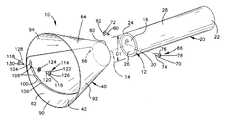
- FIG. 1is an exploded perspective view of a surgical cannula or structure constructed in accordance with a first embodiment of the present invention, the cannula being shown in an expanded condition;
- FIG. 2is a perspective view of the cannula of FIG. 1 , the cannula being shown in a contracted condition;
- FIG. 3is a rollout view of an arcuate segment of the cannula of FIG. 1 ;
- FIG. 4is an enlarged view of a slot in the arcuate segment of FIG. 3 ;
- FIG. 5is a schematic end view showing the cannula of FIG. 1 in the expanded condition
- FIG. 6is a schematic sectional view of the cannula of FIG. 1 adjacent a vertebrae of a patient's spine during a surgical procedure.
- FIG. 7is a schematic perspective view of a surgical cannula or structure constructed in accordance with a second embodiment of the present invention, the cannula being shown in an expanded condition;
- FIG. 8is a rollout view of an arcuate segment of the cannula of FIG. 7 ;
- FIG. 9is a schematic perspective view of a surgical cannula or structure constructed in accordance with a third embodiment of the present invention, the cannula being shown in an expanded condition;
- FIG. 10is a rollout view of an arcuate segment of the cannula of FIG. 9 ;
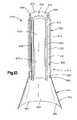
- FIG. 11is a schematic perspective view of a surgical cannula or structure constructed in accordance with a fourth embodiment of the present invention, the cannula being shown in an expanded condition;
- FIG. 12is an enlarged rollout view of an arcuate segment of the cannula of FIG. 11 ;
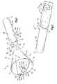
- FIG. 13is a schematic sectional view of a surgical cannula or structure constructed in accordance with a fifth embodiment of the present invention.
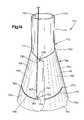
- FIG. 14is a schematic perspective view of a surgical cannula or structure constructed in accordance with a sixth embodiment of the present invention.
- FIG. 15is a rollout view of an embodiment of an arcuate segment of the cannula of FIG. 14 ;
- FIG. 16is a rollout view of another embodiment of an arcuate segment of the cannula of FIG. 14 ;
- FIG. 17is a rollout view of another embodiment of an arcuate segment of the cannula of FIG. 14 ;
- FIG. 18is a rollout view of another embodiment of an arcuate segment of the cannula of FIG. 14 ;
- FIG. 19is a rollout view of another embodiment of an arcuate segment of the cannula of FIG. 14 ;
- FIG. 20is an enlarged view of a slot in the arcuate segment of FIG. 19 .
- the present inventionis directed to a cannula or structure for receiving surgical instruments during a surgical procedure.
- the present inventionis applicable to a variety of surgical procedures in which endoscopic, percutaneous, or minimally invasive surgical techniques are used.
- FIG. 1illustrates a cannula 10 constructed according to a first embodiment of the present invention.
- the cannula 10may be a tubular structure 12 centered on an axis 14 .
- the cannula 10may be any other conduit or elongated structure which defines a passage therethrough.
- the tubular structure 12defines a passage 16 through the cannula 10 .
- Surgical instrumentsare inserted into the body during surgery through the passage 16 .
- the tubular structure 12comprises a first tubular portion 20 and a second tubular portion 40 attached to the first tubular portion.
- the first tubular portion 20is preferably made of a length of stainless steel tubing, but could alternatively be made of another suitable material, such as a radiolucent material.
- the first tubular portion 20has a proximal end 22 and a distal end 24 .
- Parallel cylindrical inner and outer surfaces 26 and 28extend between the ends 22 , 24 of the first tubular portion 20 .
- the first tubular portion 20has a thickness measured perpendicular to the surfaces 26 and 28 in the range of 0.02 inches to 0.04 inches or approximately 0.5 mm to approximately 1.0 mm. It is contemplated that the tubular portion 20 could have any desired thickness.
- the inner surface 26( FIG. 1 ) defines a first passage portion 30 of the passage 16 through the cannula 10 .
- the first passage portion 30has a diameter D1 which is preferably in the range from 10 mm to 30 mm or approximately 0.4 inches to approximately 1.2 inches. It is contemplated that the first passage portion 30 could have any desired diameter.
- the inner surface 26may have a non-reflective coating to reduce glare on any video image produced by a video camera attached to an endoscope inserted through the passage 16 .
- the second tubular portion 40 of the tubular structure 12is attached to the distal end 24 of the first tubular portion 20 .
- the second tubular portion 40is preferably made from stainless steel, but could alternatively be made from another suitable material, such as a radiolucent material.
- the second tubular portion 40includes an arcuate segment 42 of sheet stock.
- the arcuate segment 42includes first and second edges 44 and 46 .
- the arcuate segment 42also includes first and second planar edges 48 and 50 extending between the edges 44 and 46 .
- the first and second planar edges 48 and 50are rolled in an overlapping manner to form the tubular configuration of the second tubular portion 40 .
- first and second edges 44 and 46define oppositely disposed first and second ends 60 and 62 of the second tubular portion.
- the first and second ends 60 and 62are connected by a central portion 64 .
- the first end 60 of the second tubular portion 40is attached to the distal end 24 of the first tubular portion 20 by a suitable fastener, such as a rivet 66 . It is contemplated that a screw could be used instead of the rivet 66 .
- the rivet 66extends through two aligned apertures 68 at the first end 60 of the second tubular portion 40 .
- the rivet 66has a first portion 70 and a second portion 72 .
- the first portion 70has a shaft 74 extending from a head 76 .
- the shaft 74extends through the apertures 68 in the tubular portion 40 and the head 76 engages the inner surface 26 of the first tubular portion 20 .
- a cylindrical opening 78extends through the shaft 74 and the head 76 .
- the second portion 72 of the rivet 66has a shaft 80 extending from a head 82 .
- the shaft 80extends into the opening 78 in the first portion 68 of the rivet 66 and the head 82 engages the second tubular portion 40 .
- the shaft 80 of the second portion 72extends into the opening 78 in the first portion 70 to connect the first and second portions of the rivet 66 and pivotally connect the second tubular portion 40 to the first tubular portion 20 .
- the second tubular portion 40( FIG. 1 ) includes parallel inner and outer surfaces 90 and 92 extending between the first and second ends 60 and 62 .
- the inner surface 90defines a second passage portion 94 of the passage 16 through the cannula 10 which extends as a continuation of the first passage portion 30 in the first tubular portion 20 .
- the second tubular portion 40has a thickness measured perpendicular to the surfaces 90 and 92 in the range of 0.003 inches to 0.007 inches or approximately 0.075 mm to approximately 0.175 mm.
- the second tubular portion 40may have any desired thickness.
- the inner surfacemay have a non-reflective coating that reduces glare on any video image produced by a camera attached to an endoscope inserted through the passage 16 .
- An arcuate slot 100( FIGS. 1 and 3 ) is formed in the second tubular portion 40 and extends between the inner and outer surfaces 90 and 92 of the second tubular portion.
- the arcuate slot 100extends in a circumferential direction and along a curvilinear path in the central portion 64 of the second tubular portion 40 toward the end 62 of the second tubular portion.
- the arcuate slot 100has a first end 102 located in the central portion 64 of the second tubular portion 40 .
- a second end 104 of the arcuate slot 100is located adjacent the intersection of the second edge 46 and the planar edge 48 of the arcuate segment 42 .
- the arcuate slot 100( FIGS. 3 and 4 ) has three notches or stops 106 between the ends 102 and 104 .
- the notches 106define three expanded conditions of the second tubular portion 40 .
- the notches 106at least partially define a retaining mechanism for resisting movement of the second tubular portion 40 from the expanded conditions toward a contracted condition.
- the notches 106extend in directions transverse to the circumferential direction in which the slot 100 extends. Although the present invention shows three stops 106 , it is contemplated that the slot could have any number of stops.
- a guide member or rivet 114( FIGS. 1 and 3 ) is attached to the inner surface 90 of the second tubular portion 40 adjacent the intersection of the second edge 46 and the planar edge 50 . It is contemplated that a guide pin or screw could be used instead of the rivet 114 . In the tubular configuration of the second tubular portion 40 , the guide member 114 is located in the arcuate slot 100 and is movable along the curvilinear path of the arcuate slot.
- the rivet 114( FIG. 1 ) is generally similar to the rivet 66 and, therefore, will not be described in detail.
- the rivet 114has a first portion 116 and a second portion 118 .
- the first portion 116has a shaft 120 extending from a head 122 .
- the shaft 120extends through the slot 100 and the head 122 engages a washer 124 .
- a cylindrical opening 126extends through the shaft 120 and the head 122 .
- the second portion 118 of the rivet 114has a shaft 128 extending from a head 130 .
- the shaft 128extends into the opening 126 in the first portion 116 of the rivet 114 and the head 130 engages the outer surface 92 of the second tubular portion 40 .
- the shaft 120extends into the opening 126 to connect the first portion 116 of the rivet 114 to the second portion 118 .
- the second tubular portion 40 of the tubular structure 12is expandable from a contracted condition, shown in FIG. 2 , to any one of three expanded conditions, one of which is shown in FIG. 1 .
- the guide member 114In the contracted condition, the guide member 114 is located in the first end 102 of the arcuate slot 100 in the second tubular portion 40 .
- the second passage portion 94 defined by the second tubular portion 40is cylindrical in shape.
- the second passage portion 94has a generally constant diameter D 2 which is approximately equal to the diameter D 1 of the first tubular portion 20 .
- the cross-sectional area of the second passage portion 94 at the second end 62 of the second tubular portion 40is approximately the same as the cross-sectional area at the first end 60 of the second tubular portion and is approximately the same as the cross-sectional area of the first passage portion 30 in the first tubular portion 20 .
- the guide member 114engages one of the stops 106 and is located in one of the notches 106 in the arcuate slot 100 in the second tubular portion 40 . It is also contemplated that the guide member 114 could engage one of the stops 106 and be located between adjacent notches 106 .
- the stops 106retain the guide member 114 in one of a plurality of positions relative to the slot 100 and resist movement of the guide member from one of the plurality of positions relative to the slot. Accordingly, the stops 106 resist contraction of the second tubular portion 40 .
- the second tubular portion 40has a conical configuration when in the expanded conditions.
- the configuration of the second tubular portion 40 when inside the body of a patientwill vary depending on the forces exerted by surrounding tissue on the second tubular portion.
- the second passage portion 94has a diameter D 3 which is larger than the diameter D 2 of the second passage portion at the first end 60 .
- the cross-sectional area of the second passage portion 94 at the second end 62 of the second tubular portion 40is greater than the cross-sectional area of the second passage portion at the first end 60 of the second tubular portion.
- the cannula 10may include an outer member (not shown) for maintaining the second tubular portion 40 of the cannula in the contracted condition. It is contemplated that other suitable means for maintaining the second tubular portion 40 in the contracted condition could be employed.
- the outer membermay be a layer of plastic tubing which is heat shrunk over both the first and second tubular portions 20 and 40 to hold the second tubular portion in the contracted condition.
- a loop of nylon string(not shown) for tearing the heat shrink tubing is wrapped around the heat shrink tubing so that it extends both underneath and on top of the tubing. An outer end of the string extends beyond the tubing.
- the cannula 10( FIG. 6 ) is inserted over a dilator, as known in the art, and through an incision into a body 138 of a patient in the contracted condition.
- the second tubular portion 40is inserted inside the body 138 .
- the first tubular portion 20is inserted into the incision so that the first tubular portion extends from an exterior of the body 138 to inside the body.
- the outer end of the stringis then manually pulled on by the surgeon. Pulling on the string tears the heat shrink tubing.
- the heat shrink tubingremains on the cannula 10 . With the heat shrink tubing torn, the second tubular portion 40 of the cannula 10 is thereby released for expansion toward one of the expanded conditions.
- an expansion tool(not shown) is inserted into the passage 16 in the cannula 10 .
- the expansion toolis manually operated, causing a radially outwardly directed force to be exerted on the inner surface 90 of the second tubular portion 40 by the tool.
- the second tubular portion 40expands toward one of the expanded conditions.
- the guide member 114slides from the first end 102 of the arcuate slot 100 toward the second end 102 of the arcuate slot to permit the expansion of the second tubular portion 40 .
- the guide member 114engages a first stop 106 to position the guide member relative to the slot 100 . If the second tubular portion 40 needs to be expanded further, additional force is applied to the second tubular portion to move the guide member 114 .
- Expansion of the second tubular portion 40can be stopped when the guide member 114 engages one of the stops 106 .
- the guide member 114engages the stops 106 to position the guide member in any one of the plurality of positions relative to the slot 100 .
- the stops 106resist movement of the guide member 114 relative to the slot 100 .
- the second tubular portion 40has a plurality of expanded conditions.
- the expansion toolis then removed so that one or more surgical instruments (indicated schematically at 140 in FIG. 6 ) can be received through the cannula 10 and inserted into a patient's body 138 .
- the expandable second tubular portion 40 of the cannula 10provides a large working area for the surgeon inside the body 140 within the confines of the cannula. Furthermore, the second tubular portion 40 provides a working area that is only as large as needed. As a result, the simultaneous use of a number of surgical instruments, including but not limited to steerable instruments, shavers, dissectors, scissors, forceps, retractors, dilators, endoscopes, screwdrivers, distractors, burrs, kerrisons, and rongeurs, is made possible by the expandable cannula 10 .
- FIGS. 7–8A cannula or structure 210 constructed according to a second embodiment of the present invention is illustrated in FIGS. 7–8 .
- the cannula 210includes a tubular structure 212 .
- the tubular structure 212defines a passage 216 through the cannula 210 .
- Surgical instrumentsare inserted into the body during surgery through the passage 216 .
- the tubular structure 212comprises a first tubular portion 220 and a second tubular portion 240 attached to the first tubular portion.
- the first tubular portion 220is identical to the first tubular portion 20 described in connection with the embodiment disclosed in FIGS. 1–6 . Accordingly, the first tubular portion 220 will not be described in detail.
- the second tubular portion 240 of the tubular structure 212is attached to a distal end 224 of the first tubular portion 220 .
- the second tubular portion 240includes an arcuate segment 242 of sheet stock.
- the arcuate segment 242includes first and second edges 244 and 246 .
- the arcuate segment 242also includes first and second planar edges 248 and 250 extending between the edges 244 and 246 .
- the first and second planar edges 248 and 250are rolled in an overlapping manner to form the tubular configuration of the second tubular portion 240 .
- first and second arcuate edges 244 and 246define oppositely disposed first and second ends 260 and 262 ( FIG. 7 ) of the second tubular portion.
- the first and second ends 260 and 262are connected by a central portion 264 .
- the first end 260 of the second tubular portion 240is attached to the distal end 224 of the first tubular portion 220 by a suitable fastener, such as a rivet 266 .
- the rivet 266extends through two aligned apertures 268 ( FIG. 8 ) at the first end 260 of the second tubular portion 240 .
- the rivet 266is identical to the rivet 66 described in connection with the embodiment illustrated in FIGS. 1–6 . Accordingly, the rivet 266 will not be described in detail. It is contemplated that a screw could be used instead of the rivet 266 .
- the second tubular portion 240( FIG. 7 ) includes parallel inner and outer surfaces 290 and 292 extending between the first and second ends 260 and 262 .
- the inner surface 290defines a second passage portion 294 of the passage 216 through the cannula 210 which extends as a continuation of a first passage portion 230 in the first tubular portion 220 .
- An arcuate slot 270( FIGS. 7 and 8 ) is formed in the second tubular portion 240 and extends between the inner and outer surfaces 290 and 292 of the second tubular portion.
- the arcuate slot 270extends in a circumferential direction and along a curvilinear path in the central portion 264 of the second tubular portion 240 toward the end 262 of the second tubular portion.
- the arcuate slot 270has a first end 272 located in the central portion 264 of the second tubular portion 240 .
- a second end 274 of the arcuate slot 270is located adjacent the intersection of the second edge 246 and the planar edge 248 of the arcuate segment 242 .
- a guide member or tab 280extends from the second tubular portion 240 at a location adjacent the intersection of the second edge 246 and the planar edge 250 of the arcuate segment 242 .
- the tab 280is formed by bending a cut-out of the arcuate segment 242 to extend through the slot 270 .
- the tab 280is located in the arcuate slot 270 and is movable along the curvilinear path of the arcuate slot.
- the second tubular portion 240 of the tubular structure 212is expandable from a contracted condition to an expanded condition.
- the guide member 280is located in the first end 272 of the arcuate slot 270 in the second tubular portion 240 .
- the second passage portion 294 defined by the second tubular portion 240is cylindrical in shape.
- the second passage portion 294has a generally constant diameter which is approximately equal to the diameter of the first tubular portion 220 .
- the cross-sectional area of the second passage portion 294 at the second end 262 of the second tubular portion 240is approximately the same as a cross-sectional area at the first end 260 of the second tubular portion and is approximately the same as a cross-sectional area of the first passage portion 230 in the first tubular portion 220 .
- the guide member 280is located in the second end 274 of the arcuate slot 270 in the second tubular portion 240 .
- the second tubular portion 240has a conical configuration. The configuration of the second tubular portion 240 when inside the body of a patient will vary depending on the forces exerted by surrounding tissue on the second tubular portion.
- the second passage portion 294has a diameter which is larger than the diameter of the second passage portion at the first end 260 .
- the cross-sectional area of the second passage portion 294 at the second end 262 of the second tubular portion 240is greater than the cross-sectional area of the second passage portion at the first end 260 of the second tubular portion.
- the cannula 210is inserted over a dilator and through an incision into the body of a patient in the contracted condition.
- the second tubular portion 240is inserted inside the body.
- the first tubular portion 220is inserted into the incision so that the first tubular portion extends from an exterior of the body to inside the body.
- a member, such as heat shrunk tubing, holding the second tubular portion 240 in the contracted conditionis torn after insertion of the cannula 210 .
- An expansion tool(not shown) is inserted into the passage 216 in the cannula 210 .
- the expansion toolis manually operated, causing a radially outwardly directed force to be exerted on the inner surface 290 of the second tubular portion 240 by the tool.
- the second tubular portion 240expands toward the expanded condition.
- the guide member 280slides from the first end 272 of the arcuate slot 270 to the second end 274 of the arcuate slot to permit the expansion of the second tubular portion 240 .
- the expansion toolis then removed so that one or more surgical instruments can be received through the cannula 210 and inserted into a patient's body.
- the expandable second tubular portion 240 of the cannula 210provides a large working area for the surgeon inside the body within the confines of the cannula.
- simultaneous use of a number of surgical instrumentsincluding but not limited to steerable instruments, shavers, dissectors, scissors, forceps, retractors, dilators, endoscopes, screwdrivers, distractors, burrs, kerrisons, and rongeurs, is made possible by the expandable cannula 210 .
- FIGS. 9–10A cannula or structure 310 constructed according to a third embodiment of the present invention is illustrated in FIGS. 9–10 .
- the cannula 310includes a tubular structure 312 .
- the tubular structure 312defines a passage 316 through the cannula 310 .
- Surgical instrumentsare inserted into the body during surgery through the passage 316 .
- the tubular structure 312comprises a first tubular portion 320 and a second tubular portion 340 attached to the first tubular portion.
- the first tubular portion 320has a proximal end 322 and a distal end 324 .
- Parallel cylindrical inner and outer surfacesextend between the ends 322 and 324 of the first tubular portion 320 .
- the inner surfacedefines a first passage portion 330 of the passage 316 through the cannula 310 .
- the second tubular portion 340 of the tubular structure 312is attached to the distal end 324 of the first tubular portion 320 .
- the second tubular portion 340includes an arcuate segment 342 of sheet stock.
- the arcuate segment 342includes first and second edges 344 and 346 .
- the arcuate segment 342also includes first and second planar edges 348 and 350 extending between the edges 344 and 346 .
- the first and second planar edges 348 and 350are rolled in an overlapping manner to form the tubular configuration of the second tubular portion 340 .
- first and second edges 344 and 346define oppositely disposed first and second ends 360 and 362 of the second tubular portion.
- the first and second ends 360 and 362are connected by a central portion 364 .
- the first end 360 of the second tubular portion 340is attached to the distal end 324 of the first tubular portion 320 by a suitable fastener, such a rivet 366 .
- the rivet 366is identical to the rivet 66 described in connection with the embodiment illustrated in FIGS. 1–6 . Accordingly, the rivet 366 will not be described in detail.
- the rivet 366extends through aligned apertures 368 ( FIG. 10 ) at the first end 360 of the second tubular portion 340 . It is contemplated that a screw could be used instead of the rivet 366 .
- the first end 360 ( FIGS. 9 and 10 ) of the second tubular portion 340is also attached to the distal end 324 of the first tubular portion 320 by a tab 368 extending from the distal end 324 of the first tubular portion 320 .
- the tab 368extends through an opening 370 in the second tubular portion 340 and is bent over to connect the second tubular portion to the first tubular portion 320 .
- the end of the tab 368 extending through the opening 370may also be spot welded, soldered, or braized to the first tubular portion 320 .
- the second tubular portion 340includes parallel inner and outer surfaces 390 and 392 extending between the first and second ends 360 and 362 .
- the inner surface 390defines a second passage portion 394 of the passage 316 through the cannula 310 which extends as a continuation of the first passage portion 330 in the first tubular portion 320 .
- An arcuate slot 372is formed in the second tubular portion 340 and extends between the inner and outer surfaces 390 and 392 of the second tubular portion.
- the arcuate slot 372extends in a circumferential direction and along a curvilinear path in the central portion 364 of the second tubular portion 340 toward the end 362 of the second tubular portion.
- the arcuate slot 372has a first end 374 located in the central portion 364 of the second tubular portion 340 .
- a second end 376 of the arcuate slot 372is located adjacent the intersection of the second edge 346 and the planar edge 348 of the arcuate segment 342 .
- Guide members or tabs 378 and 380extend from the second tubular portion 340 adjacent the intersection of the second edge 346 and the planar edge 350 of the arcuate segment 342 .
- the tabs 378 and 380are formed by bending cut-outs of the arcuate segment 342 to extend through the slot 370 .
- the tabs 378 and 380are located in the arcuate slot 372 and are movable along the curvilinear path of the arcuate slot.
- the second tubular portion 340 of the tubular structure 312is expandable from a contracted condition to an expanded condition.
- the tabs 378 and 380are located in the first end 374 of the arcuate slot 372 in the second tubular portion 340 .
- the second passage portion 394 defined by the second tubular portion 340is cylindrical in shape.
- the second passage 394has a generally constant diameter which is approximately equal to the diameter of the first tubular portion 320 .
- the cross-sectional area of the second passage portion 394 at the second end 362 of the second tubular portion 340is approximately the same as the cross-sectional area at the first end 360 of the second tubular portion and is approximately the same as the cross-sectional area of the first passage portion 330 in the first tubular portion 320 .
- the tabs 378 and 380are located in the second end 376 of the arcuate slot 372 in the second tubular portion 340 .
- the second tubular portion 340has a conical configuration. The configuration of the second tubular portion 340 when inside the body of a patient will vary depending on the forces exerted by surrounding tissue on the second tubular portion.
- the second passage portion 394has a diameter which is larger than the diameter of the second passage portion at the first end 360 .
- the cross-sectional area of the second passage portion 394 at the second end 362 of the second tubular portion 340is greater than the cross-sectional area of the second passage portion at the first end 360 of the second tubular portion.
- the cannula 310is inserted through an incision into the body of a patient in the contracted condition.
- the second tubular portion 340is inserted inside the body.
- the first tubular portion 320is inserted into the incision so that the first tubular portion extends from an exterior of the body to inside the body.
- a member, such as heat shrunk tubing, holding the second tubular portion in the contracted conditionis torn after insertion of the cannula 310 .
- An expansion tool(not shown) is inserted into the passage 316 in the cannula 310 .
- the expansion toolis manually operated, causing a radially outwardly directed force to be exerted on the inner surface 390 of the second tubular portion 340 by the tool.
- the second tubular portion 340expands toward the expanded condition.
- the tabs 378 and 380slide from the first end 374 of the arcuate slot 372 to the second end 376 of the arcuate slot to permit the expansion of the second tubular portion 340 .
- the expandable second tubular portion 340 of the cannula 310provides a large working area for the surgeon inside the body within the confines of the cannula. As a result, the simultaneous use of a number of surgical instruments is made possible by the expandable cannula 310 .
- FIGS. 11–12A cannula or structure 410 constructed according to a fourth embodiment of the present invention is illustrated in FIGS. 11–12 .
- the cannula 410includes a tubular structure 412 .
- the tubular structure 412defines a passage 416 through the cannula 410 .
- Surgical instrumentsare inserted into the body during surgery through the passage 416 .
- the tubular structure 412comprises a first tubular portion 420 and a second tubular portion 440 attached to the first tubular portion.
- the first tubular portion 420has a proximal end 422 and a distal end 424 .
- Parallel cylindrical inner and outer surfacesextend between the ends 422 and 424 of the first tubular portion 420 .
- the inner surfacedefines a first passage portion 430 of the passage 416 through the cannula 410 .
- the second tubular portion 440 of the tubular structure 412is attached to the distal end 424 of the first tubular portion 420 .
- the second tubular portion 440includes a plurality of arcuate segments 442 of sheet stock.
- the present inventionhas five arcuate segments 442 . However, it is contemplated that any number of arcuate segments 442 could be used.
- the arcuate segments 442are identical. Accordingly, only one of the arcuate segments 442 will be described in detail.
- the arcuate segment 442( FIG. 12 ) includes first and second arcuate edges 444 and 446 .
- the arcuate segment 442also includes first and second planar edges 448 and 450 extending between the arcuate edges 444 and 446 .
- the planar edges 448 and 450 of the arcuate segments 442overlap each other to form the tubular configuration of the second tubular portion 440 .
- the arcuate edges 444 and 446define oppositely disposed first and second ends 460 and 462 of the second tubular portion.
- the first and second ends 460 and 462are connected by central portions 464 of the arcuate segments 442 .
- the first end 460 of the second tubular portion 440is attached to the distal end 424 of the first tubular portion 420 by suitable fasteners, such as rivets 466 .
- the rivets 466extend through aligned apertures 468 at the first end 460 of the second tubular portion 440 . It is contemplated that screws could be used instead of the rivets 466 .
- Each of the arcuate segments 442includes parallel inner and outer surfaces 490 and 492 extending between the first and second ends 460 and 462 of the second tubular portion 440 .
- the inner surfaces 490define a second passage portion 494 of the passage 416 through the cannula 410 which extends as a continuation of the first passage portion 430 in the first tubular portion 420 .
- Arcuate slots 470are formed in the arcuate segments 442 and extend between the inner and outer surfaces 490 and 492 of the second tubular portion 440 .
- the arcuate slots 470extend in circumferential directions and along curvilinear paths in the central portions 464 of the arcuate segments 442 toward the end 462 of the second tubular portion.
- the arcuate slots 470have first ends 472 located in the central portions 464 .
- Second ends 474 of the arcuate slots 470are located adjacent the end 462 of the second tubular portion 440 .
- Guide members or rivets 478are attached to the arcuate segments 442 .
- the guide members 478are identical to the guide member 114 described in connection with the embodiment illustrated in FIGS. 1–6 .
- the guide members 478will not be described in detail. It is contemplated that guide pins or screws could be used instead of the rivets 478 .
- the guide members 478are located in the arcuate slots 470 and are movable along the curvilinear paths of the arcuate slots.
- the second tubular portion 440 of the tubular structure 412is expandable from a contracted condition to an expanded condition.
- the guide members 478are located in the first ends 472 of the arcuate slots 470 in the second tubular portion 440 .
- the second passage portion 494 defined by the second tubular portion 440is cylindrical in shape.
- the second passage 494has a generally constant diameter which is approximately equal to the diameter of the first tubular portion 420 .
- the cross-sectional area of the second passage portion 494 at the second end 462 of the second tubular portion 440is approximately the same as the cross-sectional area at the first end 460 of the second tubular portion and is approximately the same as the cross-sectional area of the first passage portion 430 in the first tubular portion 420 .
- the guide members 478are located in the second ends 474 of the arcuate slots 470 in the second tubular portion 440 .
- the second tubular portion 440has a conical configuration. The configuration of the second tubular portion 440 when inside the body of a patient will vary depending on the forces exerted by surrounding tissue on the second tubular portion.
- the second passage portion 494has a diameter which is larger than the diameter of the second passage portion at the first end 460 .
- the cross-sectional area of the second passage portion 494 at the second end 462 of the second tubular portion 440is greater than the cross-sectional area of the second passage portion at the first end 460 of the second tubular portion.
- the cannula 410is inserted over a dilator and through an incision into the body of a patient in the contracted condition.
- the second tubular portion 440is inserted inside the body.
- the first tubular portion 420is inserted into the incision so that the first tubular portion extends from an exterior of the body to inside the body.
- a member, such as heat shrunk tubing, holding the second tubular portion 440 in the contracted conditionis torn after insertion of the cannula 410 .
- An expansion tool(not shown) is inserted into the passage 416 in the cannula 410 .
- the expansion toolis manually operated, causing a radially outwardly directed force to be exerted on the inner surfaces 490 of the second tubular portion 440 by the tool.
- the second tubular portion 440expands toward the expanded condition.
- the guide members 478slide from the first ends 472 of the arcuate slots 470 to the second ends 474 of the arcuate slots to permit the expansion of the second tubular portion 440 .
- the expandable second tubular portion 440 of the cannula 410provides a large working area for the surgeon inside the body within the confines of the cannula. As a result, the simultaneous use of a number of surgical instruments is made possible by the expandable cannula 410 .
- the slots 470are shown as not having stops, it is contemplated that the slots could have stops or notches similar to the stops 106 described in connection with the embodiment illustrated in FIGS. 1–6 .
- FIG. 13A cannula or structure 510 constructed according to a fifth embodiment of the present invention is illustrated in FIG. 13 .
- the cannula 510includes a tubular structure 512 .
- the tubular structure 512defines a passage 516 through the cannula 510 .
- Surgical instrumentsare inserted into the body during surgery through the passage 516 .
- the tubular structure 512comprises a first tubular portion 520 and a second tubular portion 540 attached to the first tubular portion.
- the first and second tubular portions 520 and 540are identical to the first and second tubular portions 20 and 40 described in connection with the embodiment disclosed in FIGS. 1–6 . Accordingly, the first and second tubular portions 520 and 540 will not be described in detail.
- the second tubular portion 540 of the tubular structure 512is attached to a distal end 524 of the first tubular portion 520 .
- a first end 560 of the second tubular portion 540is attached to the distal end 524 of the first tubular portion 520 by a suitable fastener (not shown), such as a rivet.
- the second tubular portion 540includes parallel inner and outer surfaces 590 and 592 extending between first and second ends 560 and 562 .
- the inner surface 590defines a second passage portion 594 of the passage 516 through the cannula 510 which extends as a continuation of a first passage portion 530 in the first tubular portion 520 .
- the second tubular portion 540 of the tubular structure 512is expandable from a contracted condition to an expanded condition.
- the second passage portion 594 defined by the second tubular portion 540is cylindrical in shape.
- the second passage portion 594has a generally constant diameter which is approximately equal to the diameter of the first tubular portion 520 .
- the cross-sectional area of the second passage portion 594 at the second end 562 of the second tubular portion 540is approximately the same as a cross-sectional area at the first end 560 of the second tubular portion and is approximately the same as a cross-sectional area of the first passage portion 530 in the first tubular portion 520 .
- the second tubular portion 540In the expanded condition, the second tubular portion 540 has a conical configuration.
- the configuration of the second tubular portion 540 when inside the body of a patientwill vary depending on the forces exerted by surrounding tissue.
- the second passage portion 594At the second end 562 of the second tubular portion 540 , the second passage portion 594 has a diameter which is larger than the diameter of the second passage portion at the first end 560 .
- the cross-sectional area of the second passage portion 594 at the second end 562 of the second tubular portion 540is greater than the cross-sectional area of the second passage portion at the first end 560 of the second tubular portion.
- a second tubular structure 600extends into the first tubular portion 520 of the tubular structure 512 .
- the second tubular portion 600extends into the first passage portion 530 .
- the second tubular structure 600has a radially extending flange 602 with openings 604 for receiving surgical instruments and/or for application of suction or irrigation fluid.
- a tube 608may extend from the flange 602 adjacent one of the openings 604 for receiving a surgical instrument and/or the application of suction or irrigation fluid.
- the second tubular structure 600includes parallel inner and outer surfaces 610 and 612 .
- the inner surface 610defines a passage 616 through the second tubular structure 600 .
- the outer surface 612 and the inner surface 626 of the first tubular portion 520define an annular passage 620 .
- the openings 604 in the flange 602 of the second tubular structure 600communicate with the annular passage 620 . Accordingly, surgical instruments extend through the openings 604 into the annular passage 620 .
- the cannula 510is inserted over a dilator and through an incision into the body of a patient in the contracted condition.
- the second tubular portion 540is inserted inside the body.
- the first tubular portion 520is inserted into the incision so that the first tubular portion extends from an exterior of the body to inside the body.
- a member, such as heat shrunk tubing, holding the second tubular portion 540 in the contracted conditionis torn after insertion of the cannula 510 .
- an expansion tool(not shown) is inserted into the passage 516 in the cannula 510 .
- the expansion toolis manually operated, causing a radially outwardly directed force to be exerted on the inner surface 590 of the second tubular portion 540 by the tool.
- the second tubular portion 540expands toward the expanded condition.
- the expansion toolis then removed so that the second tubular structure 600 may be inserted into the passage 516 .
- the second tubular structure 600is inserted into the passage 516 to define the annular passage 620 .
- Surgical instrumentscan be received through the openings 604 in the flange 602 and into the annular passage 620 and one or more surgical instruments can be received through the passage 616 and/or suction or irrigation fluid can be applied through the passage 616 .
- suction or irrigation fluidcan be applied through the passage 616 .
- FIGS. 14 and 15A cannula or structure 710 constructed according to a sixth embodiment of the present invention is illustrated in FIGS. 14 and 15 .
- the cannula 710includes a tubular structure 712 .
- the tubular structure 712defines a passage 716 through the cannula 710 .
- Surgical instrumentsare inserted into the body during a surgery through the passage 716 .
- the tubular structure 712includes a first tubular portion 720 and a second tubular portion 740 attached to the first tubular portion.
- the first tubular portion 720is identical to the first tubular portion 20 described in connection with the embodiment disclosed in FIGS. 1–6 . Accordingly, the first tubular portion 720 will not be described in detail.
- the second tubular portion 740 of the tubular structure 712is attached to a distal end 724 of the first tubular portion 720 .
- the second tubular portion 740includes an arcuate segment 742 of sheet stock.
- the arcuate segment 742includes upper and lower edges 744 and 746 .
- the arcuate segment 742also includes first and second edges 748 and 750 extending between the edges 744 and 746 .
- the first and second edges 748 and 750are rolled in an overlapping manner to form the tubular configuration of the second tubular portion 740 .
- the lower edge 746includes two semi-circular cut-outs 752 .
- a spinal fixation element or rodmay pass through the cut-outs 52 during a surgical procedure when the second tubular portion 740 is in an expanded condition.
- the upper and lower edges 744 and 746define oppositely disposed first and second ends 760 and 762 ( FIG. 14 ) of the second tubular portion.
- the first and second ends 760 and 762are connected by a central portion 764 .
- the first end 760 of the second tubular portion 740is attached to the distal end 724 of the first tubular portion 720 by a suitable fastener, such as a rivet 766 .
- the rivet 766extends through two aligned apertures 768 ( FIG. 15 ) at the first end 760 of the second tubular portion 740 .
- the rivet 766may have any desired configuration. It is also contemplated that a screw could be used instead of the rivet 766 .
- the second tubular portion 740( FIG. 14 ) includes parallel inner and outer surfaces 790 and 792 extending between the first and second ends 760 and 762 .
- the inner surface 790defines a second passage portion 794 of the passage 716 through the cannula 710 which extends as a continuation of a first passage portion 730 in the first tubular portion 720 .
- a first slot 770( FIGS. 14 and 15 ) is formed in the second tubular portion 740 and extends between the inner and outer surfaces 790 and 792 of the second tubular portion.
- the first slot 770extends in a circumferential direction and along a curvilinear path in the central portion 764 of the second tubular portion 740 toward the end 762 of the second tubular portion.
- the first slot 770has a first end 772 located in the central portion 764 of the second tubular portion 740 .
- a second end 774 of the first slot 770is located adjacent the intersection of the lower edge 746 and the first edge 748 of the arcuate segment 742 .
- the slot 770( FIG. 15 ) includes a stop portion 776 extending in a proximal direction from the second end 774 of the slot. It is contemplated that the stop portion 776 may alternatively extend from an intermediate location on the slot 770 .
- the second tubular portion 740may be initially expanded to the expanded condition, and subsequently retained or locked in a slightly smaller intermediate condition.
- the stop portion 776extends transverse to the circumferential direction and defines a stop 778 .
- the stop 778defines a retaining mechanism for resisting movement of the second tubular portion 740 from the expanded condition toward a contracted condition.
- a second slot 780( FIGS. 14 and 15 ) is formed in the second tubular portion 740 and extends between the inner and outer surfaces 790 and 792 of the second tubular portion.
- the second slot 780extends in a circumferential direction and along a curvilinear path in the central portion 764 of the second tubular portion 740 toward the end 762 of the second tubular portion.
- the second slot 780has a first end 782 located in the central portion 764 of the second tubular portion 740 .
- a second end 784 of the second slot 780is located adjacent the intersection of the lower edge 746 and the second edge 750 of the arcuate segment 742 .
- the slot 780includes a stop portion 786 extending in a proximal direction from the second end 784 .
- the stop portion 786extends transverse to the circumferential direction and defines a stop 788 .
- the stop 788defines the retaining mechanism for resisting movement of the second tubular portion 740 from the expanded condition toward the contracted condition.
- a guide member or rivet 791extends through the first and second slots 770 and 780 in the second tubular portion 740 .
- the rivet 791may have any desired configuration. It is also contemplated that a guide pin or screw could be used instead of the rivet 791 .
- the guide member 791In the tubular configuration of the second tubular portion 740 , the guide member 791 is located in the slots 770 and 780 and is movable along the curvilinear path of the slots.
- the rivet 791extends through two washers 793 , one of which is shown in FIG. 14 , and the slots 780 and 770 .
- One of the washers 793engages the inner surface 790 of the second tubular portion 740 .
- the other washer 793engages the outer surface 792 of the second tubular portion 740 .
- the second tubular portion 740 of the tubular structure 712is expandable from the contracted condition to the expanded condition.
- the guide member 791is located in the first ends 772 and 782 of the slots 770 and 780 in the second tubular portion 740 .
- the second passage portion 794 defined by the second tubular portion 740is cylindrical in shape.
- the second passage portion 794has a generally constant diameter which is approximately equal to the diameter of the first tubular portion 720 .
- the cross-sectional area of the second passage portion 794 at the second end 762 of the second tubular portion 740is approximately the same as a cross-sectional area at the first end 760 of the second tubular portion and is approximately the same as a cross-sectional area of the first passage portion 730 in the first tubular portion 720 .
- the guide member 791is located in the second ends 774 and 784 of the slots 770 and 780 .
- the second tubular portion 740has a conical configuration. The configuration of the second tubular portion 740 when inside the body of a patient will vary depending on the forces exerted by surrounding tissue.
- the second passage portion 794has a diameter which is larger than the diameter of the second passage portion at the first end 760 .
- a cross-sectional area of the second passage portion 794 at the second end 762 of the second tubular portion 740is greater than the cross-sectional area of the second passage portion at the first end 760 of the second tubular portion.
- the guide member 791may be moved relative to the second tubular portion 740 from the second end portions 774 and 784 of the slots 770 and 780 into the stop portions 776 and 786 of the slots.
- the stops 778 and 788engage the guide member 791 to resist movement of the second tubular portion 740 from the expanded condition toward the contracted condition.
- the cannula, or structure, 710is provided with a locking mechanism.
- a locking mechanismis understood to refer to an arrangement of parts which prevents movement of the tubular portion 740 from a predetermined condition towards the contracted condition (or alternatively, toward the expanded condition).
- the predetermined conditionis understood to refer to the expanded condition or any other desirable intermediate condition.
- the predetermined conditionmay refer to a particular cross-sectional area, or alternatively, to a particular range of cross-sectional areas, as discussed below.
- the locking mechanismWhen engaged, the locking mechanism maintains the tubular portion 740 in the predetermined condition against forces which may be exerted by surrounding tissue to move the tubular portion 740 towards the contracted condition.
- the stops 778 and 788 and guide member 791function as a locking mechanism, e.g., stops 778 and 788 may engage the guide member 791 and thereby prevent movement of the guide member 791 in a circumferential direction.
- the range of motion available with respect to the predetermined conditionis determined by the width of the stop portions 776 and 786 .
- the locking mechanismmaintains the tubular portion 740 in a substantially fixed configuration. Consequently, relative movement of the first and second edges 748 and 750 with respect to each other is substantially prevented.
- stop portions 776 and 786are wider than the guide member 791 in a circumferential direction, the tubular portion 740 may be able to move within a range of cross-sectional areas, and the first and second edges 748 and 750 are allowed a commensurate degree of relative movement.
- the guide member 791may be moved into the stop portions 776 and 786 of the slots 770 and 780 by a tether member 798 .
- the tether member 798is substantially rigid and may be made of any suitable material, such as Nitinol.
- the tether member 798has a first end 800 connected with the guide member 791 .
- the tether member 800may be connected with the guide member 791 in any suitable manner. It is contemplated that the tether member 798 may be formed as one piece with the washer 793 located on the outside of the second tubular portion 740 . It is also contemplated that the tether member 798 may be connected with the second tubular portion 740 to move the second tubular portion relative to the guide member 791 .
- the tether member 798extends from the guide member 791 along the length of the first and second tubular portions 720 and 740 along the outside of the cannula 710 .
- the tether member 798may be moved in a proximal direction relative to the cannula 710 to move the guide member 791 into the stop portions 776 and 786 of the slots 770 and 780 .
- the tether member 798may be moved in a distal direction relative to the cannula 710 to move the guide member 791 out of the stop portions 776 and 786 and into the second ends 774 and 784 to permit contraction of the second tubular portion 740 .
- the tether member 798may extend through the passage 716 in the cannula 710 and be connected to the guide member 791 . It is also contemplated that the tether member 798 may be a suture or nylon string used to pull the guide member 791 into the stop portions 776 and 786 and a tool could be used to move the guide member from the stop portions. It is also contemplated that the tether member 798 may not be used. A tool could be inserted into the passage 716 to move the guide member 791 into the stop portions 776 and 786 .
- the cannula 710is inserted over a dilator and through an incision into the body of a patient in the contracted condition.
- the second tubular portion 740is inserted inside the body.
- the first tubular portion 720is inserted into the incision so that the first tubular portion extends from an exterior of the body to inside the body.
- a member, such as heat shrunk tubing, for maintaining the second tubular portion 740 in the contracted conditionmay also hold the tether member 798 adjacent the outer surface of the cannula 710 during insertion of the cannula.
- the member holding the second tubular portion 740 in the contracted conditionis torn after insertion of the cannula.
- An expansion tool(not shown) is inserted into the passage 716 in the cannula 710 .
- the expansion toolis manually operated, causing a radially outwardly directed force to be exerted on the inner surface 790 of the second tubular portion 740 by the tool.
- the second tubular portion 740expands toward the expanded condition.
- the guide member 791slides from the first ends 772 and 782 of the slots 770 and 780 toward the second ends 774 and 784 of the slots to permit the expansion of the second tubular portion 740 .
- the tether member 798is moved proximally relative to the cannula 710 to move the guide member 791 into the stop portions 776 and 786 of the slots 770 and 780 .
- the stops 778 and 788 on the second tubular portion 740engage the guide member 791 to resist movement of the second tubular portion 740 from the expanded condition toward the contracted condition.
- the expansion toolis removed so that one or more surgical instruments can be received through the cannula 710 and inserted into a patient's body.
- the tether member 798Upon conclusion of the surgical procedure, the tether member 798 is moved distally relative to the cannula 710 .
- the tether member 798moves the guide member 791 from the stop portions 776 and 786 of the slots 770 and 780 into the second ends 774 and 784 .
- the second tubular portion 740can move from the expanded condition into the contracted condition for removal of the cannula 710 from the body of the patient.
- the expandable second tubular portion 740 of the cannula 710provides a large working area for the surgeon inside the body within the confines of the cannula.
- simultaneous use of a number of surgical instrumentsincluding but not limited to steerable instruments, shavers, dissectors, scissors, forceps, retractors, dilators, endoscopes, screwdrivers, distractors, burrs, kerrisons, and rongeurs, is made possible by the expandable cannula 710 .
- a second tubular portion 840includes an arcuate segment 842 of sheet stock.
- the arcuate segment 842includes upper and lower edges 844 and 846 .
- the arcuate segment 842also includes first and second edges 848 and 850 extending between the edges 844 and 846 .
- the first and second edges 848 and 850are rolled in an overlapping manner to form the tubular configuration of a second tubular portion 840 .
- the lower edge 846includes two semi-circular cut-outs 852 through which a spinal fixation element may pass when the second tubular portion 840 is in an expanded condition.
- the upper and lower edges 844 and 846define oppositely disposed first and second ends 860 and 862 of the second tubular portion.
- the first and second ends 860 and 862are connected by a central portion 864 .
- the first end 860 of the second tubular portion 840is connected to the distal end 724 of the first tubular portion 720 by a suitable fastener, such as the rivet 766 .
- the rivet 766extends through two aligned apertures 868 at the first end 860 of the second tubular portion 840 . It is also contemplated that a screw could be used instead of the rivet 766 .
- the second tubular portion 840includes an inner surface 890 and a parallel outer surface extending between the first and second ends 860 and 862 .
- the inner surface 890defines a second passage portion of the passage 716 through the cannula 710 which extends as a continuation of the first passage portion 730 in the first tubular portion 720 .
- a first slot 870( FIG. 16 ) is formed in the second tubular portion 840 and extends between the inner and outer surfaces of the second tubular portion.
- the first slot 870extends in a circumferential direction and along a curvilinear path in the central portion 864 of the second tubular portion 840 toward the end 862 of the second tubular portion.
- the first slot 870has a first end 872 located in the central portion 864 of the second tubular portion 840 .
- a second end 874 of the first slot 870is located adjacent the intersection of the lower edge 846 and the first edge 848 of the arcuate segment 842 .
- the slot 870includes a stop portion 876 extending in a distal direction from the second end 874 of the slot.
- the stop portion 876extends transverse to the circumferential direction and defines a stop 878 .
- the stop 878defines a retaining mechanism for resisting movement of the second tubular portion 840 from the expanded condition toward a contracted condition.
- a second slot 880is formed in the second tubular portion 840 and extends between the inner and outer surfaces of the second tubular portion.
- the second slot 880extends in a circumferential direction and along a curvilinear path in the central portion 864 of the second tubular portion 840 toward the end 862 of the second tubular portion.
- the second slot 880has a first end 882 located in the central portion 864 of the second tubular portion 840 .
- a second end 884 of the second slot 880is located adjacent the intersection of the lower edge 846 and the second edge 850 of the arcuate segment 842 .
- the slot 880includes a stop portion 886 extending in a distal direction from the second end 884 .
- the stop portion 886extends transverse to the circumferential direction and defines a stop 888 .
- the stop 888defines the retaining mechanism for resisting movement of the second tubular portion 840 from the expanded condition toward the contracted condition.
- the guide member or rivet 791extends through the first and second slots 870 and 880 in the second tubular portion 840 . It is also contemplated that a guide pin or screw could be used instead of the rivet 791 . In the tubular configuration of the second tubular portion 840 , the guide member 791 is located in the slots 870 and 880 and is movable along the curvilinear path of the slots.
- the rivet 791extends through the washers 793 and the arcuate slots 870 and 880 .
- One of the washers 793engages the inner surface 890 of the second tubular portion 840 .
- the other washer 793engages the outer surface of the second tubular portion 840 .
- the second tubular portion 840 of the tubular structureis expandable from the contracted condition to the expanded condition.
- the guide member 791is located in the first ends 872 and 882 of the slots 870 and 880 in the second tubular portion 840 .
- the second passage portion defined by the second tubular portion 840is cylindrical in shape.
- the second passage portionhas a generally constant diameter which is approximately equal to the diameter of the first tubular portion.
- the cross-sectional area of the second passage portion and the second end 862 of the second tubular portion 840is approximately the same as a cross-sectional area at the first end 860 of the second tubular portion and is approximately the same as a cross-sectional area of the first passage portion 730 in the first tubular portion 720 .
- the second tubular portion 840has a conical configuration.
- the configuration of the second tubular portion 840 when inside the body of a patientwill vary depending on the forces exerted by surrounding tissue.
- the second passage portionhas a diameter which is larger than the diameter of the second passage portion at the first end 860 .
- a cross-sectional area of the second passage portion at the second end 862 of the second tubular portion 840is greater than the cross-sectional area of the second passage portion at the first end 860 of the second tubular portion.
- the guide member 791may be moved relative to the second tubular portion 840 from the second end portions 874 and 884 of the slots 870 and 880 into the stop portions 876 and 886 of the slots.
- the stops 878 and 888engage the guide member 791 to resist movement of the second tubular portion 840 from the expanded condition toward the contracted condition.
- the guide member 791is moved into the stop portions 876 and 886 of the slots 870 and 880 by the tether member 798 .
- the stops 878 and 888may function as a locking mechanism when guide member 791 is positioned within transversely-oriented stop portions 876 and 886 , such that the stops 878 and 888 may engage the guide member 791 and thereby prevent movement of the guide member 791 in a circumferential direction. Consequently, depending upon the width of stop portions 876 and 886 , relative movement of the first and second edges 848 and 850 with respect to each other is prevented, thereby maintaining the tubular portion 840 in the predetermined condition, e.g., an expanded or an intermediate condition.
- the predetermined conditione.g., an expanded or an intermediate condition.
- the tether member 798extends from the guide member 791 along the length of the first and second tubular portions 720 and 840 along the outside of the cannula 710 .
- the tether member 798may be moved in a distal direction relative to the cannula 710 to move the guide member 791 into the stop portions 876 and 886 of the slots 870 and 880 .
- the tether member 798may be moved in a proximal direction relative to the cannula 710 to move the guide member 791 out of the stop portions 876 and 886 and into the second ends 874 and 884 to permit contraction of the second tubular portion 840 and removal of the cannula from a body of a patient.
- a second tubular portion 940includes an arcuate segment 942 of sheet stock.
- the arcuate segment 942includes upper and lower edges 944 and 946 .
- the arcuate segment 942also includes first and second edges 948 and 950 extending between the edges 944 and 946 .
- the first and second edges 948 and 950are rolled in an overlapping manner to form the tubular configuration of the second tubular portion 940 .
- the lower edge 946includes two semi-circular cut-outs 952 through which a spinal fixation element may pass when the second tubular portion 940 is in an expanded condition.
- the upper and lower edges 944 and 946define oppositely disposed first and second ends 960 and 962 of the second tubular portion.
- the first and second ends 960 and 962are connected by a central portion 964 .
- the first end 960 of the second tubular portion 940is attached to the distal end 724 of the first tubular portion 720 by a suitable fastener, such as the rivet 766 .
- the rivet 766extends through two aligned apertures 968 at the first end 960 of the second tubular portion 940 . It is also contemplated that a screw could be used instead of the rivet 766 .
- the second tubular portion 940includes an inner surface 992 and a parallel outer surface extending between the first and second ends 960 and 962 .
- the inner surface 992defines a second passage portion of the passage 716 through the cannula 710 which extends as a continuation of the first passage portion 730 in the first tubular portion 720 .
- a first slot 970( FIG. 17 ) is formed in the second tubular portion 940 and extends between the inner and outer surfaces of the second tubular portion.
- the first slot 970extends in a circumferential direction and along a curvilinear path in the central portion 964 of the second tubular portion 940 toward the end 962 of the second tubular portion.
- the first slot 970has a first end 972 located in the central portion 964 of the second tubular portion 940 .
- a second end 974 of the first slot 970is located adjacent the intersection of the lower edge 946 and the first edge 948 of the arcuate segment 942 .
- the slot 970includes a stop portion 976 extending in a proximal direction from the second end 974 of the slot.
- the stop portion 976extends transverse to the circumferential direction and defines a stop 978 .
- the stop 978defines a retaining mechanism for resisting movement of the second tubular portion 940 from the expanded condition toward a contracted condition.
- a second slot 980is formed in the second tubular portion 940 and extends between the inner and outer surfaces of the second tubular portion.
- the second slot 980extends in a circumferential direction and along a curvilinear path in the central portion 964 of the second tubular portion 940 toward the end 962 of the second tubular portion.
- the second slot 980has a first end 982 located in the central portion 964 of the second tubular portion 940 .
- a second end 984 of the second slot 980is located adjacent the intersection of the lower edge 946 and the second edge 950 of the arcuate segment 942 .
- the slot 980includes a stop portion 986 extending in a proximal direction from the second end 984 .
- the stop portion 986extends transverse to the circumferential direction and defines a stop 988 .
- the slot 980also includes a second portion 990 extending from an end of the stop portion 986 spaced from the second end 984 and transverse to the stop portion.
- the second portion 990extends parallel to the circumferential direction.
- the stop portion 988 and the second portion 990define a retaining mechanism for resisting movement of the second tubular portion 940 from the expanded condition toward the contracted condition.
- the guide member or rivet 791extends through the first and second slots 970 and 980 in the second tubular portion 940 . It is contemplated that a guide pin or screw could be used instead of the rivet 791 . In the tubular configuration of the second tubular portion 940 , the guide member 791 is located in the slots 970 and 980 and is movable along the curvilinear path of the slots.
- the rivet 791extends through the washers 793 and the arcuate slots 980 and 970 .
- One of the washers 793engages the inner surface 992 of the second tubular portion.
- the other washer 793engages the outer surface of the second tubular portion 940 .
- the second tubular portion 940 of the tubular structureis expandable from the contracted condition to the expanded condition.
- the guide member 791is located in the first ends 972 and 982 of the arcuate slots 970 and 980 in the second tubular portion 940 .
- the second passage portion defined by the second tubular portion 940is cylindrical in shape.
- the second passage portionhas a generally constant diameter which is approximately equal to the diameter of the first tubular portion.
- the cross-sectional area of the second passage portion and the second end 962 of the second tubular portion 940is approximately the same as a cross-sectional area at the first end 960 of the second tubular portion and is approximately the same as a cross-sectional area of the first passage portion 730 in the first tubular portion 720 .
- the second tubular portion 940has a conical configuration.
- the configuration of the second tubular portion 940 when inside the body of a patientwill vary depending on the forces exerted by surrounding tissue.
- the second passage portionhas a diameter which is larger than the diameter of the second passage portion at the first end 960 .
- a cross-sectional area of the second passage portion at the second end 962 of the second tubular portion 940is greater than the cross-sectional area of the second passage portion at the first end 960 of the second tubular portion.
- the guide member 791may be moved relative to the second tubular portion 940 from the second end portions 974 and 984 of the slots 970 and 980 into the stop portions 976 and 986 of the slots.
- the stops 978 and 988engage the guide member 791 to resist movement of the second tubular portion 940 from the expanded condition toward the contracted condition.
- the guide member 791may be further moved into the second portion 990 of the slot 980 to further resist movement of the second tubular portion 940 from the expanded condition toward the contracted condition.
- the guide member 791is moved into the stop portions 976 and 986 and the second portion 990 of the slot 980 by the tether member 798 .
- the stops 978 , 988 and 990may function as a locking mechanism when guide member 791 is positioned within transversely-oriented stop portions 976 and 986 , e.g., stops 978 , 988 and 990 may engage the guide member 791 and thereby prevent movement of the guide member 791 in a circumferential direction. Consequently, depending upon the width of stop portions 976 and 986 , relative movement of the first and second edges 948 and 950 with respect to each other is prevented, thereby maintaining the tubular portion 840 in the predetermined condition, e.g., an expanded or an intermediate condition.
- the predetermined conditione.g., an expanded or an intermediate condition.
- the tether member 798extends from the guide member 791 along the length of the first and second tubular portions 720 and 940 along the outside of the cannula 710 .
- the tether member 798may be moved in a proximal direction relative to the cannula 710 to move the guide member 791 into the stop portions 976 and 986 .
- the tether member 798may be moved in a distal direction relative to the cannula 710 to move the guide member 791 out of the stop portions 976 and 986 and into the second ends 974 and 984 to permit contraction of the second tubular portion 940 and removal of the cannula from a body of a patient.
- FIG. 18Another embodiment of a second tubular portion for use with the first tubular portion 720 , illustrated in FIG. 14 , is illustrated in FIG. 18 .
- a second tubular portion 1040is substantially identical to second tubular portion 740 , described herein, with the differences noted herein.
- Second tubular portion 1040includes an arcuate segment 1042 of sheet stock.
- the arcuate segment 1042includes upper and lower edges 1044 and 1046 .
- the arcuate segment 1042also includes first and second edges 1048 and 1050 extending between the edges 1044 and 1046 .
- the first and second edges 1048 and 1050are rolled in an overlapping manner to form the tubular configuration of the second tubular portion 1040 .
- the lower edge 1046includes two semi-circular cut-outs 1052 through which a spinal fixation element may pass when the second tubular portion 1040 is in an expanded condition.
- the upper and lower edges 1044 and 1046define oppositely disposed first and second ends 1060 and 1062 of the second tubular portion.
- the first and second ends 1060 and 1062are connected by a central portion 1064 .
- the first end 1060 of the second tubular portion 1040is attached to the distal end 724 of the first tubular portion 720 by a suitable fastener, such as the rivet 766 .
- the rivet 766extends through two aligned apertures 1068 at the first end 1060 of the second tubular portion 1040 . It is also contemplated that a screw could be used instead of the rivet 766 .
- the second tubular portion 1040includes an inner surface 1092 and a parallel outer surface extending between the first and second ends 1060 and 1062 .
- the inner surface 1092defines a second passage portion of the passage 716 through the cannula 710 which extends as a continuation of the first passage portion 730 in the first tubular portion 720 .
- a first slot 1076( FIG. 18 ) is formed in the second tubular portion 1040 and is located adjacent the intersection of the lower edge 1046 and the first edge 1048 of the arcuate segment 1042 .
- the slot 1076extends transverse to the circumferential direction in a substantially axial direction and defines a stop 1078 .
- the stop 1078defines a retaining mechanism for resisting movement of the second tubular portion 1040 from the expanded condition toward a contracted condition.
- a second slot 1080is formed in the second tubular portion 1040 and extends between the inner and outer surfaces of the second tubular portion.
- the second slot 1080extends in a circumferential direction and along a curvilinear path in the central portion 1064 of the second tubular portion 1040 toward the end 1062 of the second tubular portion.
- the second slot 1080has a first end 1082 located in the central portion 1064 of the second tubular portion 1040 .
- a second end 1084 of the second slot 1080is located adjacent the intersection of the lower edge 1046 and the second edge 1050 of the arcuate segment 1042 .
- the slot 1080includes a stop portion 1086 extending in a proximal direction from the second end 1084 .
- the stop portion 1086extends transverse to the circumferential direction and defines a stop 1088 .
- the stop 1088defines a retaining mechanism for resisting movement of the second tubular portion 1040 from the expanded condition toward the contracted condition.
- the stop 1088may function as a locking mechanism when guide member 791 is positioned within transversely-oriented stop portion 1086 , e.g., stop 1088 may engage the guide member 791 and thereby prevent movement of the guide member 791 in a circumferential direction.
- the predetermined conditione.g., expanded condition or an intermediate condition.
- the guide member or rivet 791extends through the first and second slots 1076 and 1080 in the second tubular portion 1040 . It is contemplated that a guide pin or screw could be used instead of the rivet 791 . In the tubular configuration of the second tubular portion 1040 , the guide member 791 is located in the slots 1076 and 1080 and is movable along the curvilinear path of the slot 1080 .
- the rivet 791extends through the washers 793 and the slots 1080 and 1076 .
- One of the washers 793engages the inner surface 1092 of the second tubular portion.
- the other washer 793engages the outer surface of the second tubular portion 1040 .
- the second tubular portion 1040 of the tubular structureis expandable from the contracted condition to the expanded condition.
- the guide member 791is located in the first slot 1076 and the first end 1082 of the arcuate slot 1080 in the second tubular portion 1040 .
- the second passage portion defined by the second tubular portion 1040is cylindrical in shape.
- the second passage portionhas a generally constant diameter which is approximately equal to the diameter of the first tubular portion.
- the cross-sectional area of the second passage portion and the second end 1062 of the second tubular portion 1040is approximately the same as a cross-sectional area at the first end 1060 of the second tubular portion and is approximately the same as a cross-sectional area of the first passage portion 730 in the first tubular portion 720 .
- the second tubular portion 1040has a conical configuration.
- the configuration of the second tubular portion 1040 when inside the body of a patientwill vary depending on the forces exerted by surrounding tissue.
- the second passage portionhas a diameter which is larger than the diameter of the second passage portion at the first end 1060 .
- a cross-sectional area of the second passage portion at the second end 1062 of the second tubular portion 1040is greater than the cross-sectional area of the second passage portion at the first end 1060 of the second tubular portion.
- the guide member 791may be moved relative to the second tubular portion 1040 from the second end portion 1084 of the slot 1080 into the stop portion 1086 of the second slot 1080 and transversely within the first slot 1076 .
- the stops 1078 and 1088engage the guide member 791 to resist movement of the second tubular portion 1040 from the expanded condition toward the contracted condition.
- the guide member 791is moved into the stop portion 1086 by the tether member 798 .
- the tether member 798extends from the guide member 791 along the length of the first and second tubular portions 720 and 1040 along the outside of the cannula 710 .
- the tether member 798may be moved in a proximal direction relative to the cannula 710 to move the guide member 791 into the stop portions 1076 and 1086 .
- the tether member 798may be moved in a distal direction relative to the cannula 710 to move the guide member 791 out of the stop portion 1086 and into the second end 1084 to permit contraction of the second tubular portion 1040 and removal of the cannula from a body of a patient.
- a second tubular portion 1140includes an arcuate segment 1142 of sheet stock.
- the arcuate segment 1142includes upper and lower edges 1144 and 1146 .
- the arcuate segment 1142also includes first and second edges 1148 and 1150 extending between the edges 1144 and 1146 .
- the first and second edges 1148 and 1150are rolled in an overlapping manner to form the tubular configuration of a second tubular portion 1140 .
- edges 1148 and 1150are rolled so that the edge 1148 is located on the inside of the second tubular portion 1140 and the edge 1150 is located on the outside of the second tubular portion.
- the lower edge 1146includes two semi-circular cutouts 1152 through which a spinal fixation element may pass when the second tubular portion 1140 is in an expanded condition.
- the upper and lower edges 1144 and 1146define oppositely disposed first and second ends 1160 and 1162 of the second tubular portion.
- the first and second ends 1160 and 1162are connected by a central portion 1164 .
- the first end 1160 of the second tubular portion 1140is connected to the distal end 724 of the first tubular portion 720 by a suitable fastener, such as the rivet 766 .
- the rivet 766extends through two aligned apertures 1168 at the first end 1160 of the second tubular portion 1140 . It is also contemplated that a screw could be used instead of the rivet 766 .
- the second tubular portion 1140includes an inner surface 1190 and a parallel outer surface extending between the first and second ends 1160 and 1162 .
- the inner surface 1190defines a second passage portion of the passage 716 through the cannula 710 which extends as a continuation of the first passage portion 730 in the first tubular portion 720 .
- a first slot 1170( FIG. 19 ) is formed in the second tubular portion 1140 and extends between the inner and outer surfaces of the second tubular portion.
- the first slot 1170extends in a circumferential direction and along a curvilinear path in the central portion 1164 of the second tubular portion 1140 toward the end 1162 of the second tubular portion.
- the first slot 1170has a first end 1172 located in the central portion 1164 of the second tubular portion 1140 .
- a second end 1174 of the first slot 1170is located adjacent the intersection of the lower edge 1146 and the first edge 1148 of the arcuate segment 1142 .
- the first slot 1170is defined by opposite edges 1176 and 1178 .
- the edges 1176 and 1178are spaced apart a first distance adjacent the first end 1172 of the slot 1170 .
- the opposite edges 1176 and 1178( FIG. 20 ) are spaced apart a second distance, which is less than the first distance, at six locations along the slot 1170 to define six stops 1179 between the ends 1172 and 1174 .
- the stops 1179define six expanded conditions of the second tubular portion 1140 .
- the stops 1179at least partially define a retaining mechanism for resisting movement of the second tubular portion 1140 from the expanded conditions toward a contracted condition and/or another expanded condition.
- the stops 1179extend in directions transverse to the circumferential direction in which the slot 1170 extends. Although the present invention shows six stops 1179 , it is contemplated that the slot 1170 could have any number of stops.
- a second slot 1180( FIG. 19 ) is formed in the second tubular portion 1140 and extends between the inner and outer surfaces of the second tubular portion.
- the second slot 1180extends in a circumferential direction and along a curvilinear path in the central portion 1164 of the second tubular portion 1140 toward the end 1162 of the second tubular portion.
- the second slot 1180has a first end 1182 located in the central portion 1164 of the second tubular portion 1140 .
- a second end 1184 of the second slot 1180is located adjacent the intersection of the lower edge 1146 and the second edge 1150 of the arcuate segment 1142 .
- the edges of the second slot 1180do not define stops, it is contemplated that opposite edges of the slot 1180 may define stops similar to stops 1179 .
- the guide member or rivet 791extends through the first and second slots 1170 and 1180 in the second tubular portion 1140 . It is also contemplated that a guide pin or screw could be used instead of the rivet 791 . In the tubular configuration of the second tubular portion 1140 , the guide member 791 is located in the slots 1170 and 1180 and is moveable along the curvilinear path of the slots.
- the rivet 791extends through the washers 793 and the arcuate slots 1170 and 1180 .
- One of the washers 793engages the inner surface 1190 of the second tubular portion 1140 .
- the other washer 793engages the outer surface of the second tubular portion 1140 .
- the second tubular portion 1140 of the tubular structureis expandable from the contracted condition to any one of six expanded conditions.
- the guide member 791is located in the first ends 1172 and 1182 of the slots 1170 and 1180 in the second tubular portion 1140 .
- the second passage portion defined by the second tubular portion 1140is cylindrical in shape.
- the second passage portionhas a generally constant diameter which is approximately equal to the diameter of the first tubular portion.
- the cross-sectional area of the second passage portion and the second end 1162 of the second tubular portion 1140is approximately the same as a cross-sectional area at the first end 1160 of the second tubular portion and is approximately the same as a cross-sectional area of the first passage portion 730 in the first tubular portion 720 .
- the guide member 791engages one of the stops 1179 in the first slot 1170 .
- the stops 1179retain the guide member 791 in one of a plurality of positions relative to the slots 1170 and 1180 and resist movement of the guide member from one of the plurality of positions relative to the slots. Accordingly, the stops 1179 resist contraction and/or expansion of the second tubular portion 1140 .
- a tether memberis not needed to move the guide member 791 into the stops 1179 .
- the second tubular portion 1140has a conical configuration when in the expanded conditions.
- the configuration of the second tubular portion 1140 when inside the body of a patientwill vary depending on the forces exerted by surrounding tissue.
- the second passage portionhas a diameter which is larger than the diameter of the second passage portion at the first end 1160 .
- a cross-sectional area of the second passage portion at the second end 1062 of the second tubular portion 1140is greater than the cross-sectional area of the second passage portion at the first end 1160 of the second tubular portion.
- the cannula 710is inserted over a dilator and through an incision into the body of a patient in the contracted condition.
- the second tubular portion 1140is inserted inside the body.
- the first tubular portion 720is inserted into the incision so that the first tubular portion extends from an exterior of the body to inside the body.
- a member, such as heat shrunk tubing, for maintaining the second tubular portion 1140 in the contracted conditionis torn after insertion of the cannula.
- An expansion tool(not shown) is inserted into the passage 716 in the cannula 710 .
- the expansion toolis manually operated, causing a radially outwardly directed force to be exerted on the inner surface 1190 of the second tubular portion 1140 by the tool.
- the second tubular portion 1140expands toward one of the expanded conditions.
- the guide member 791slides from the first ends 1172 and 1182 of the slots 1170 and 1180 toward the second ends 1174 and 1184 of the slots to permit the expansion of the second tubular portion 1140 .
- the guide member 791engages a first stop 1179 to position the guide member relative to the slots 1170 and 1180 .
- the second tubular portion 1140needs to be expanded further, additional force is applied to the second tubular portion to move the guide member 791 . Expansion of the second tubular portion 1140 can be stopped when the guide member 791 engages any of the stops 1179 .
- the guide member 791engages the stops 1179 to position the guide member in any one of the plurality of positions relative to the slots 1170 and 1180 .
- the stops 1179resist movement of the guide member 791 relative to the slots 1170 and 1180 .
- the second tubular portion 1140has a plurality of expanded conditions. The expansion tool is then removed so that one or more surgical instruments can be received through the cannula 710 and inserted into a patient's body.
- the cannula 710Upon conclusion of the surgical procedure, the cannula 710 is removed from the incision. The cannula 710 is moved in a proximal direction relative to the body of the patient. The surrounding tissue of the body exerts forces on the second tubular portion 1140 that are large enough to contract the second tubular portion while the cannula is moving in the proximal direction. Accordingly, the guide member 791 moves toward the first ends 1172 and 1182 of the slots 1170 and 1180 as the cannula 710 is moved in the proximal direction.
- the second tubular portions disclosed in FIGS. 1–6 and 14 – 20may have one or two slots that define stops. If the second tubular portion has two slots, it is contemplated that either one or both slots could define stops. Furthermore, it is contemplated that the slots could have stop portions as disclosed in FIGS. 14–17 and define stops as disclosed in FIGS. 1–6 or FIGS. 19–20 .
Landscapes
- Health & Medical Sciences (AREA)
- Surgery (AREA)
- Life Sciences & Earth Sciences (AREA)
- Biomedical Technology (AREA)
- Nuclear Medicine, Radiotherapy & Molecular Imaging (AREA)
- Engineering & Computer Science (AREA)
- Heart & Thoracic Surgery (AREA)
- Medical Informatics (AREA)
- Molecular Biology (AREA)
- Animal Behavior & Ethology (AREA)
- General Health & Medical Sciences (AREA)
- Public Health (AREA)
- Veterinary Medicine (AREA)
- Pathology (AREA)
- Surgical Instruments (AREA)
Abstract
Description
Claims (91)
Priority Applications (5)
| Application Number | Priority Date | Filing Date | Title |
|---|---|---|---|
| US10/361,887US7144393B2 (en) | 2001-05-15 | 2003-02-10 | Structure for receiving surgical instruments |
| US10/686,063US7766930B2 (en) | 2001-05-15 | 2003-10-15 | Cannula for receiving surgical instruments |
| PCT/US2004/001664WO2004071334A2 (en) | 2003-02-10 | 2004-01-22 | Structure for receiving surgical instruments |
| US10/973,745US8007492B2 (en) | 2001-05-15 | 2004-10-26 | Cannula for receiving surgical instruments |
| US11/634,372US7985218B2 (en) | 2001-05-15 | 2006-12-05 | Structure for receiving surgical instruments |
Applications Claiming Priority (2)
| Application Number | Priority Date | Filing Date | Title |
|---|---|---|---|
| US09/855,358US6524320B2 (en) | 2001-05-15 | 2001-05-15 | Cannula for receiving surgical instruments |
| US10/361,887US7144393B2 (en) | 2001-05-15 | 2003-02-10 | Structure for receiving surgical instruments |
Related Parent Applications (1)
| Application Number | Title | Priority Date | Filing Date |
|---|---|---|---|
| US09/855,358Continuation-In-PartUS6524320B2 (en) | 2001-05-15 | 2001-05-15 | Cannula for receiving surgical instruments |
Related Child Applications (3)
| Application Number | Title | Priority Date | Filing Date |
|---|---|---|---|
| US10/686,063DivisionUS7766930B2 (en) | 2001-05-15 | 2003-10-15 | Cannula for receiving surgical instruments |
| US10/973,745DivisionUS8007492B2 (en) | 2001-05-15 | 2004-10-26 | Cannula for receiving surgical instruments |
| US11/634,372ContinuationUS7985218B2 (en) | 2001-05-15 | 2006-12-05 | Structure for receiving surgical instruments |
Publications (2)
| Publication Number | Publication Date |
|---|---|
| US20030153927A1 US20030153927A1 (en) | 2003-08-14 |
| US7144393B2true US7144393B2 (en) | 2006-12-05 |
Family
ID=32867965
Family Applications (4)
| Application Number | Title | Priority Date | Filing Date |
|---|---|---|---|
| US10/361,887Expired - LifetimeUS7144393B2 (en) | 2001-05-15 | 2003-02-10 | Structure for receiving surgical instruments |
| US10/686,063Active2026-07-21US7766930B2 (en) | 2001-05-15 | 2003-10-15 | Cannula for receiving surgical instruments |
| US10/973,745Expired - Fee RelatedUS8007492B2 (en) | 2001-05-15 | 2004-10-26 | Cannula for receiving surgical instruments |
| US11/634,372Expired - Fee RelatedUS7985218B2 (en) | 2001-05-15 | 2006-12-05 | Structure for receiving surgical instruments |
Family Applications After (3)
| Application Number | Title | Priority Date | Filing Date |
|---|---|---|---|
| US10/686,063Active2026-07-21US7766930B2 (en) | 2001-05-15 | 2003-10-15 | Cannula for receiving surgical instruments |
| US10/973,745Expired - Fee RelatedUS8007492B2 (en) | 2001-05-15 | 2004-10-26 | Cannula for receiving surgical instruments |
| US11/634,372Expired - Fee RelatedUS7985218B2 (en) | 2001-05-15 | 2006-12-05 | Structure for receiving surgical instruments |
Country Status (2)
| Country | Link |
|---|---|
| US (4) | US7144393B2 (en) |
| WO (1) | WO2004071334A2 (en) |
Cited By (47)
| Publication number | Priority date | Publication date | Assignee | Title |
|---|---|---|---|---|
| US20040097907A1 (en)* | 2001-05-15 | 2004-05-20 | Dipoto Gene P. | Cannula for receiving surgical instruments |
| US20040116954A1 (en)* | 1998-08-20 | 2004-06-17 | Endius Inc. | Surgical tool for use in expanding a cannula |
| US20050090833A1 (en)* | 2003-10-24 | 2005-04-28 | Dipoto Gene | Methods and apparatuses for fixation of the spine through an access device |
| US20050171551A1 (en)* | 2003-10-21 | 2005-08-04 | William Sukovich | Instrument and method for preparing a bone to receive an implant |
| US20050215858A1 (en)* | 2002-03-07 | 2005-09-29 | Vail William B Iii | Tubular personal pelvic viewers |
| US20050251196A1 (en)* | 2004-05-06 | 2005-11-10 | Endius Incorporated | Surgical tool for use in expanding a tubular structure |
| US20060030850A1 (en)* | 2004-07-23 | 2006-02-09 | Keegan Thomas E | Methods and apparatuses for percutaneous implant delivery |
| US20070021750A1 (en)* | 2005-07-20 | 2007-01-25 | Shluzas Alan E | Apparatus for connecting a longitudinal member to a bone portion |
| US20070027364A1 (en)* | 2005-07-28 | 2007-02-01 | Stefan Schwer | Expandable access device |
| US20070106123A1 (en)* | 2005-09-26 | 2007-05-10 | Josef Gorek | Minimally invasive retractor and methods of use |
| US20070260125A1 (en)* | 2006-05-02 | 2007-11-08 | Strauss Kevin R | Minimally open retraction device |
| US20070288026A1 (en)* | 2006-06-09 | 2007-12-13 | Endius, Inc. | Methods and apparatus for access to and/or treatment of the spine |
| US20080077143A1 (en)* | 2006-09-25 | 2008-03-27 | Zimmer Spine, Inc. | Apparatus for connecting a longitudinal member to a bone portion |
| US20080221627A1 (en)* | 2002-06-24 | 2008-09-11 | Shluzas Alan E | Surgical instrument for moving vertebrae |
| US20090222045A1 (en)* | 2008-02-28 | 2009-09-03 | K2M, Inc. | Minimally Invasive Retractor and Methods of Use |
| US20090222046A1 (en)* | 2008-02-28 | 2009-09-03 | K2M, Inc. | Minimally Invasive Retraction Device Having Removable Blades |
| US20090221878A1 (en)* | 2008-02-28 | 2009-09-03 | K2M, Inc. | Minimally Invasive Retractor with Separable Blades and Methods of Use |
| US20090221879A1 (en)* | 2008-02-28 | 2009-09-03 | K2M, Inc. | Minimally Invasive Retractor Having Separable Blades |
| US20090221877A1 (en)* | 2008-02-28 | 2009-09-03 | K2M, Inc. | Minimally Invasive Retraction Device Having Detachable Blades |
| US20090222044A1 (en)* | 2008-02-28 | 2009-09-03 | K2M, Inc. | Minimally Invasive Retractor Screw and Methods of Use |
| US7641670B2 (en) | 1998-08-20 | 2010-01-05 | Zimmer Spine, Inc. | Cannula for receiving surgical instruments |
| US7670354B2 (en) | 1998-08-20 | 2010-03-02 | Zimmer Spine, Inc. | Cannula for receiving surgical instruments |
| US7691120B2 (en) | 2003-08-26 | 2010-04-06 | Zimmer Spine, Inc. | Access systems and methods for minimally invasive surgery |
| US20100217090A1 (en)* | 2009-02-26 | 2010-08-26 | Heiges Bradley A | Retractor and mounting pad |
| US20100217088A1 (en)* | 2009-02-26 | 2010-08-26 | Heiges Bradley A | Surgical dilator, retractor and mounting pad |
| US7799036B2 (en) | 1998-08-20 | 2010-09-21 | Zimmer Spine, Inc. | Method and apparatus for securing vertebrae |
| US7850695B2 (en) | 2000-08-01 | 2010-12-14 | Zimmer Spine, Inc. | Method of securing vertebrae |
| US8016828B2 (en) | 2005-09-27 | 2011-09-13 | Zimmer Spine, Inc. | Methods and apparatuses for stabilizing the spine through an access device |
| US20120277757A1 (en)* | 2011-04-13 | 2012-11-01 | Curax, Llc | Multi-function cannulated surgical device |
| US20140058438A1 (en)* | 2012-08-21 | 2014-02-27 | St. Jude Medical Puerto Rico Llc | Carrier tubes for closure devices |
| US8663227B2 (en) | 2011-12-03 | 2014-03-04 | Ouroboros Medical, Inc. | Single-unit cutting head systems for safe removal of nucleus pulposus tissue |
| US8956284B2 (en) | 2011-01-20 | 2015-02-17 | K2M, Inc. | Minimally invasive retractor and posted screw |
| US8979749B2 (en) | 2007-04-17 | 2015-03-17 | K2M, Inc. | Minimally open interbody access retraction device and surgical method |
| US20150080896A1 (en) | 2013-07-19 | 2015-03-19 | Ouroboros Medical, Inc. | Anti-clogging device for a vacuum-assisted, tissue removal system |
| US9168047B2 (en) | 2009-04-02 | 2015-10-27 | John T. To | Minimally invasive discectomy |
| US20160100857A1 (en)* | 2014-04-23 | 2016-04-14 | Applied Medical Resources Corporation | System and methods for tissue removal |
| US20160262794A1 (en)* | 2014-11-13 | 2016-09-15 | Applied Medical Resources Corporation | Systems and methods for tissue removal |
| US9554789B2 (en) | 2013-04-17 | 2017-01-31 | DePuy Synthes Products, Inc. | Expandable dilator |
| WO2017040275A1 (en) | 2015-08-28 | 2017-03-09 | Bhdl Holdings, Llc | Surgical dilator, retractor and mounting pad |
| US9675334B2 (en) | 2009-02-26 | 2017-06-13 | Bhdl Holdings, Llc | Surgical dilator, retractor and mounting pad |
| US9788856B2 (en) | 2014-03-11 | 2017-10-17 | Stryker European Holdings I, Llc | Endoscopic surgical systems and methods |
| US10149674B2 (en) | 2015-08-12 | 2018-12-11 | K2M, Inc. | Orthopedic surgical system including surgical access systems, distraction systems, and methods of using same |
| WO2018231830A1 (en) | 2017-06-12 | 2018-12-20 | Bhdl Holdings, Llc | Surgical dilator, retractor and mounting pad |
| US10413287B2 (en) | 2009-02-26 | 2019-09-17 | Bhdl Holdings, Llc | Surgical dilator, retractor and mounting pad |
| US10499894B2 (en) | 2015-08-12 | 2019-12-10 | K2M, Inc. | Orthopedic surgical system including surgical access systems, distraction systems, and methods of using same |
| US20210077155A1 (en)* | 2013-05-13 | 2021-03-18 | Neo Medical Sa | Orthopedic Implant Kit |
| US11701097B2 (en) | 2012-07-17 | 2023-07-18 | Warsaw Orthopedic, Inc. | Surgical retractor and method of use |
Families Citing this family (139)
| Publication number | Priority date | Publication date | Assignee | Title |
|---|---|---|---|---|
| US7985247B2 (en) | 2000-08-01 | 2011-07-26 | Zimmer Spine, Inc. | Methods and apparatuses for treating the spine through an access device |
| DE10154163A1 (en) | 2001-11-03 | 2003-05-22 | Advanced Med Tech | Device for straightening and stabilizing the spine |
| US6793678B2 (en) | 2002-06-27 | 2004-09-21 | Depuy Acromed, Inc. | Prosthetic intervertebral motion disc having dampening |
| US6648888B1 (en) | 2002-09-06 | 2003-11-18 | Endius Incorporated | Surgical instrument for moving a vertebra |
| WO2004039235A2 (en)* | 2002-10-25 | 2004-05-13 | Endius Incorporated | Apparatus and methods for shielding body structures during surgery |
| US7025791B2 (en)* | 2002-12-02 | 2006-04-11 | Gi Dynamics, Inc. | Bariatric sleeve |
| US7608114B2 (en) | 2002-12-02 | 2009-10-27 | Gi Dynamics, Inc. | Bariatric sleeve |
| US7766973B2 (en) | 2005-01-19 | 2010-08-03 | Gi Dynamics, Inc. | Eversion resistant sleeves |
| WO2004049982A2 (en) | 2002-12-02 | 2004-06-17 | Gi Dynamics, Inc. | Bariatric sleeve |
| US7695446B2 (en) | 2002-12-02 | 2010-04-13 | Gi Dynamics, Inc. | Methods of treatment using a bariatric sleeve |
| US7678068B2 (en) | 2002-12-02 | 2010-03-16 | Gi Dynamics, Inc. | Atraumatic delivery devices |
| US7645232B2 (en)* | 2003-05-16 | 2010-01-12 | Zimmer Spine, Inc. | Access device for minimally invasive surgery |
| US7226451B2 (en)* | 2003-08-26 | 2007-06-05 | Shluzas Alan E | Minimally invasive access device and method |
| WO2005032358A2 (en)* | 2003-10-02 | 2005-04-14 | Endius, Inc. | Methods, systems and apparatuses for performing minimally invasive spinal procedures |
| US20050090899A1 (en)* | 2003-10-24 | 2005-04-28 | Dipoto Gene | Methods and apparatuses for treating the spine through an access device |
| US7655012B2 (en)* | 2003-10-02 | 2010-02-02 | Zimmer Spine, Inc. | Methods and apparatuses for minimally invasive replacement of intervertebral discs |
| US20050090822A1 (en)* | 2003-10-24 | 2005-04-28 | Dipoto Gene | Methods and apparatus for stabilizing the spine through an access device |
| US8057420B2 (en) | 2003-12-09 | 2011-11-15 | Gi Dynamics, Inc. | Gastrointestinal implant with drawstring |
| AU2004305450B2 (en) | 2003-12-09 | 2009-01-08 | Gi Dynamics, Inc. | Intestinal sleeve |
| US20050251192A1 (en)* | 2004-03-31 | 2005-11-10 | Shluzas Alan E | Access device having discrete visualization locations |
| ATE506042T1 (en) | 2004-07-09 | 2011-05-15 | Gi Dynamics Inc | DEVICES FOR PLACEMENT OF A GASTROINTESTINAL SLEEVE |
| US20060052812A1 (en)* | 2004-09-07 | 2006-03-09 | Michael Winer | Tool for preparing a surgical site for an access device |
| EP1799145B1 (en) | 2004-09-17 | 2016-12-21 | GI Dynamics, Inc. | Gastrointestinal anchor |
| US7651499B2 (en)* | 2004-10-26 | 2010-01-26 | Concept Matrix, Llc | Working channel for minimally invasive spine surgery |
| US8043212B1 (en)* | 2004-11-05 | 2011-10-25 | Zimmer Spine, Inc. | Methods for treating cervical vertebrae through an access device |
| US7771382B2 (en) | 2005-01-19 | 2010-08-10 | Gi Dynamics, Inc. | Resistive anti-obesity devices |
| US7976488B2 (en) | 2005-06-08 | 2011-07-12 | Gi Dynamics, Inc. | Gastrointestinal anchor compliance |
| EP1752106A1 (en)* | 2005-08-11 | 2007-02-14 | Cardio Life Research S.A. | Surgical retractor |
| US20070049801A1 (en)* | 2005-08-24 | 2007-03-01 | Lamport Ronald B | Endoscope accessory |
| US20070233089A1 (en)* | 2006-02-17 | 2007-10-04 | Endius, Inc. | Systems and methods for reducing adjacent level disc disease |
| US20070208229A1 (en)* | 2006-03-02 | 2007-09-06 | Prusmack Chad J | Method and apparatus for minimally invasive spine surgery |
| US7819836B2 (en) | 2006-06-23 | 2010-10-26 | Gi Dynamics, Inc. | Resistive anti-obesity devices |
| US8821496B2 (en) | 2006-09-29 | 2014-09-02 | DePuy Synthes Products, LLC | Osteotomy protective cover |
| WO2008070863A2 (en) | 2006-12-07 | 2008-06-12 | Interventional Spine, Inc. | Intervertebral implant |
| US8979931B2 (en) | 2006-12-08 | 2015-03-17 | DePuy Synthes Products, LLC | Nucleus replacement device and method |
| US8801647B2 (en) | 2007-02-22 | 2014-08-12 | Gi Dynamics, Inc. | Use of a gastrointestinal sleeve to treat bariatric surgery fistulas and leaks |
| US8900307B2 (en) | 2007-06-26 | 2014-12-02 | DePuy Synthes Products, LLC | Highly lordosed fusion cage |
| US20090088789A1 (en) | 2007-09-28 | 2009-04-02 | O'neil Michael J | Balloon With Shape Control For Spinal Procedures |
| BRPI0818608A2 (en) | 2007-10-05 | 2015-04-22 | Synthes Gmbh | Sequential directional dilatation system for dilating from a nerve of a patient's anatomy, and method for forming an access opening through a psoas muscle to a patient's spine using a dilatation system |
| EP2237748B1 (en) | 2008-01-17 | 2012-09-05 | Synthes GmbH | An expandable intervertebral implant |
| US8088163B1 (en) | 2008-02-06 | 2012-01-03 | Kleiner Jeffrey B | Tools and methods for spinal fusion |
| US8936641B2 (en) | 2008-04-05 | 2015-01-20 | DePuy Synthes Products, LLC | Expandable intervertebral implant |
| US20210378834A1 (en) | 2008-05-22 | 2021-12-09 | Spinal Surgical Strategies, Inc., A Nevada Corporation D/B/A Kleiner Device Labs | Spinal fusion cage system with inserter |
| USD853560S1 (en) | 2008-10-09 | 2019-07-09 | Nuvasive, Inc. | Spinal implant insertion device |
| US8864654B2 (en) | 2010-04-20 | 2014-10-21 | Jeffrey B. Kleiner | Method and apparatus for performing retro peritoneal dissection |
| US8366748B2 (en) | 2008-12-05 | 2013-02-05 | Kleiner Jeffrey | Apparatus and method of spinal implant and fusion |
| US20110144687A1 (en)* | 2009-12-10 | 2011-06-16 | Kleiner Jeffrey | Lateral Based Retractor System |
| US9717403B2 (en) | 2008-12-05 | 2017-08-01 | Jeffrey B. Kleiner | Method and apparatus for performing retro peritoneal dissection |
| US9247943B1 (en) | 2009-02-06 | 2016-02-02 | Kleiner Intellectual Property, Llc | Devices and methods for preparing an intervertebral workspace |
| USD656610S1 (en) | 2009-02-06 | 2012-03-27 | Kleiner Jeffrey B | Spinal distraction instrument |
| US9526620B2 (en) | 2009-03-30 | 2016-12-27 | DePuy Synthes Products, Inc. | Zero profile spinal fusion cage |
| CN102448379B (en) | 2009-04-03 | 2014-11-19 | 米切尔·A·哈登布鲁克 | Surgical retractor system |
| US9138207B2 (en) | 2009-05-19 | 2015-09-22 | Teleflex Medical Incorporated | Methods and devices for laparoscopic surgery |
| US20100305407A1 (en)* | 2009-06-02 | 2010-12-02 | Farley Daniel K | Malleable Port Retractor |
| US10973656B2 (en) | 2009-09-18 | 2021-04-13 | Spinal Surgical Strategies, Inc. | Bone graft delivery system and method for using same |
| US9629729B2 (en) | 2009-09-18 | 2017-04-25 | Spinal Surgical Strategies, Llc | Biological delivery system with adaptable fusion cage interface |
| US9186193B2 (en) | 2009-09-18 | 2015-11-17 | Spinal Surgical Strategies, Llc | Fusion cage with combined biological delivery system |
| US10245159B1 (en) | 2009-09-18 | 2019-04-02 | Spinal Surgical Strategies, Llc | Bone graft delivery system and method for using same |
| US8906028B2 (en) | 2009-09-18 | 2014-12-09 | Spinal Surgical Strategies, Llc | Bone graft delivery device and method of using the same |
| US20170238984A1 (en) | 2009-09-18 | 2017-08-24 | Spinal Surgical Strategies, Llc | Bone graft delivery device with positioning handle |
| USD723682S1 (en) | 2013-05-03 | 2015-03-03 | Spinal Surgical Strategies, Llc | Bone graft delivery tool |
| USD750249S1 (en) | 2014-10-20 | 2016-02-23 | Spinal Surgical Strategies, Llc | Expandable fusion cage |
| US9060877B2 (en) | 2009-09-18 | 2015-06-23 | Spinal Surgical Strategies, Llc | Fusion cage with combined biological delivery system |
| US8685031B2 (en) | 2009-09-18 | 2014-04-01 | Spinal Surgical Strategies, Llc | Bone graft delivery system |
| US9173694B2 (en) | 2009-09-18 | 2015-11-03 | Spinal Surgical Strategies, Llc | Fusion cage with combined biological delivery system |
| US9393129B2 (en) | 2009-12-10 | 2016-07-19 | DePuy Synthes Products, Inc. | Bellows-like expandable interbody fusion cage |
| EP3251604B1 (en) | 2010-01-20 | 2020-04-22 | EON Surgical Ltd. | System of deploying an elongate unit in a body cavity |
| US8721539B2 (en) | 2010-01-20 | 2014-05-13 | EON Surgical Ltd. | Rapid laparoscopy exchange system and method of use thereof |
| US7879009B1 (en)* | 2010-01-29 | 2011-02-01 | Warsaw Orthopedic, Inc. | Variable opening delivery system for intervertebral disc therapies |
| US9907560B2 (en) | 2010-06-24 | 2018-03-06 | DePuy Synthes Products, Inc. | Flexible vertebral body shavers |
| US8979860B2 (en) | 2010-06-24 | 2015-03-17 | DePuy Synthes Products. LLC | Enhanced cage insertion device |
| US8623091B2 (en) | 2010-06-29 | 2014-01-07 | DePuy Synthes Products, LLC | Distractible intervertebral implant |
| EP2615980B1 (en) | 2010-09-19 | 2017-08-16 | EON Surgical Ltd. | Micro laparoscopy devices and deployments thereof |
| US9402732B2 (en) | 2010-10-11 | 2016-08-02 | DePuy Synthes Products, Inc. | Expandable interspinous process spacer implant |
| US8394129B2 (en) | 2011-03-10 | 2013-03-12 | Interventional Spine, Inc. | Method and apparatus for minimally invasive insertion of intervertebral implants |
| US8518087B2 (en) | 2011-03-10 | 2013-08-27 | Interventional Spine, Inc. | Method and apparatus for minimally invasive insertion of intervertebral implants |
| US9119665B2 (en)* | 2011-03-21 | 2015-09-01 | Covidien Lp | Thoracic access port including foldable anchor |
| USD707354S1 (en)* | 2011-09-19 | 2014-06-17 | ProShield LLC | Multifunctional medical probe enclosure |
| US9622779B2 (en) | 2011-10-27 | 2017-04-18 | DePuy Synthes Products, Inc. | Method and devices for a sub-splenius / supra-levator scapulae surgical access technique |
| US9808232B2 (en) | 2011-11-01 | 2017-11-07 | DePuy Synthes Products, Inc. | Dilation system |
| US8795167B2 (en) | 2011-11-15 | 2014-08-05 | Baxano Surgical, Inc. | Spinal therapy lateral approach access instruments |
| US20130158345A1 (en)* | 2011-12-19 | 2013-06-20 | Heshmat Majlessi | Veno-Merse / Harvester Device |
| US9265490B2 (en) | 2012-04-16 | 2016-02-23 | DePuy Synthes Products, Inc. | Detachable dilator blade |
| EP2877127B1 (en) | 2012-07-26 | 2019-08-21 | Synthes GmbH | Expandable implant |
| US20140067069A1 (en) | 2012-08-30 | 2014-03-06 | Interventional Spine, Inc. | Artificial disc |
| US9480855B2 (en) | 2012-09-26 | 2016-11-01 | DePuy Synthes Products, Inc. | NIR/red light for lateral neuroprotection |
| US9717601B2 (en) | 2013-02-28 | 2017-08-01 | DePuy Synthes Products, Inc. | Expandable intervertebral implant, system, kit and method |
| US9522070B2 (en) | 2013-03-07 | 2016-12-20 | Interventional Spine, Inc. | Intervertebral implant |
| US9277928B2 (en) | 2013-03-11 | 2016-03-08 | Interventional Spine, Inc. | Method and apparatus for minimally invasive insertion of intervertebral implants |
| US9993353B2 (en) | 2013-03-14 | 2018-06-12 | DePuy Synthes Products, Inc. | Method and apparatus for minimally invasive insertion of intervertebral implants |
| WO2014144086A1 (en)* | 2013-03-15 | 2014-09-18 | Ib Medical, Llc | Expandable cannula with distal locking mechanism |
| US9072501B2 (en) | 2013-03-15 | 2015-07-07 | Regents Of The University Of Minnesota | Micro-orifice surgical access system |
| US10040598B2 (en)* | 2013-08-21 | 2018-08-07 | Bellfig Creative, LLC | Foldable structures |
| EP3164080A4 (en) | 2014-07-06 | 2018-06-27 | Garcia-Bengochea, Javier | Methods and devices for surgical access |
| WO2017008087A1 (en) | 2015-07-06 | 2017-01-12 | Javier Garcia-Bengochea | Methods and devices for surgical access |
| US9980737B2 (en) | 2014-08-04 | 2018-05-29 | Medos International Sarl | Flexible transport auger |
| US9924979B2 (en) | 2014-09-09 | 2018-03-27 | Medos International Sarl | Proximal-end securement of a minimally invasive working channel |
| US10264959B2 (en) | 2014-09-09 | 2019-04-23 | Medos International Sarl | Proximal-end securement of a minimally invasive working channel |
| US10111712B2 (en) | 2014-09-09 | 2018-10-30 | Medos International Sarl | Proximal-end securement of a minimally invasive working channel |
| US11426290B2 (en) | 2015-03-06 | 2022-08-30 | DePuy Synthes Products, Inc. | Expandable intervertebral implant, system, kit and method |
| US10786264B2 (en) | 2015-03-31 | 2020-09-29 | Medos International Sarl | Percutaneous disc clearing device |
| US9913727B2 (en) | 2015-07-02 | 2018-03-13 | Medos International Sarl | Expandable implant |
| CN113143355A (en) | 2015-09-04 | 2021-07-23 | 美多斯国际有限公司 | Multi-shield spinal access system |
| US12150636B2 (en) | 2015-09-04 | 2024-11-26 | Medos International Sárl | Surgical instrument connectors and related methods |
| US11439380B2 (en) | 2015-09-04 | 2022-09-13 | Medos International Sarl | Surgical instrument connectors and related methods |
| US10987129B2 (en) | 2015-09-04 | 2021-04-27 | Medos International Sarl | Multi-shield spinal access system |
| US11672562B2 (en) | 2015-09-04 | 2023-06-13 | Medos International Sarl | Multi-shield spinal access system |
| US11744447B2 (en) | 2015-09-04 | 2023-09-05 | Medos International | Surgical visualization systems and related methods |
| USD797290S1 (en) | 2015-10-19 | 2017-09-12 | Spinal Surgical Strategies, Llc | Bone graft delivery tool |
| US10105213B2 (en)* | 2015-12-29 | 2018-10-23 | Novaplast Corporation | Prosthetic implant delivery device and method |
| US10299838B2 (en) | 2016-02-05 | 2019-05-28 | Medos International Sarl | Method and instruments for interbody fusion and posterior fixation through a single incision |
| USD783209S1 (en)* | 2016-03-08 | 2017-04-04 | Kerry Morris | Telescopic pet food funnel with handle |
| EP3474784A2 (en) | 2016-06-28 | 2019-05-01 | Eit Emerging Implant Technologies GmbH | Expandable and angularly adjustable intervertebral cages with articulating joint |
| US11510788B2 (en) | 2016-06-28 | 2022-11-29 | Eit Emerging Implant Technologies Gmbh | Expandable, angularly adjustable intervertebral cages |
| USD812316S1 (en)* | 2016-07-18 | 2018-03-06 | Ofelia Valdez | Pet food dispenser |
| EP4368128A3 (en) | 2016-09-07 | 2024-07-17 | Vertos Medical, Inc. | Percutaneous lateral recess resection methods and instruments |
| US10537436B2 (en) | 2016-11-01 | 2020-01-21 | DePuy Synthes Products, Inc. | Curved expandable cage |
| US10888433B2 (en) | 2016-12-14 | 2021-01-12 | DePuy Synthes Products, Inc. | Intervertebral implant inserter and related methods |
| HRP20230108T1 (en)* | 2017-04-25 | 2023-05-26 | Jeffrey Weinzweig M.D. | Prosthetic implant delivery device |
| US10398563B2 (en) | 2017-05-08 | 2019-09-03 | Medos International Sarl | Expandable cage |
| WO2018209042A2 (en) | 2017-05-10 | 2018-11-15 | Mako Surgical Corp. | Robotic spine surgery system and methods |
| US11033341B2 (en) | 2017-05-10 | 2021-06-15 | Mako Surgical Corp. | Robotic spine surgery system and methods |
| US11344424B2 (en) | 2017-06-14 | 2022-05-31 | Medos International Sarl | Expandable intervertebral implant and related methods |
| US10940016B2 (en) | 2017-07-05 | 2021-03-09 | Medos International Sarl | Expandable intervertebral fusion cage |
| USD847449S1 (en)* | 2017-11-03 | 2019-04-30 | Veronica Viera | Spitoon |
| US11446156B2 (en) | 2018-10-25 | 2022-09-20 | Medos International Sarl | Expandable intervertebral implant, inserter instrument, and related methods |
| US11013530B2 (en) | 2019-03-08 | 2021-05-25 | Medos International Sarl | Surface features for device retention |
| US11241252B2 (en) | 2019-03-22 | 2022-02-08 | Medos International Sarl | Skin foundation access portal |
| US11129727B2 (en) | 2019-03-29 | 2021-09-28 | Medos International Sari | Inflatable non-distracting intervertebral implants and related methods |
| US11813026B2 (en) | 2019-04-05 | 2023-11-14 | Medos International Sarl | Systems, devices, and methods for providing surgical trajectory guidance |
| US11084613B1 (en)* | 2019-09-03 | 2021-08-10 | Brian Dove | Meat grind bag filling funnel attachment |
| US11426286B2 (en) | 2020-03-06 | 2022-08-30 | Eit Emerging Implant Technologies Gmbh | Expandable intervertebral implant |
| US11771517B2 (en) | 2021-03-12 | 2023-10-03 | Medos International Sarl | Camera position indication systems and methods |
| US11850160B2 (en) | 2021-03-26 | 2023-12-26 | Medos International Sarl | Expandable lordotic intervertebral fusion cage |
| US11752009B2 (en) | 2021-04-06 | 2023-09-12 | Medos International Sarl | Expandable intervertebral fusion cage |
| USD1028646S1 (en)* | 2021-04-30 | 2024-05-28 | Opti-Harvest, Inc. | Canopy unit for light harvesting |
| US12090064B2 (en) | 2022-03-01 | 2024-09-17 | Medos International Sarl | Stabilization members for expandable intervertebral implants, and related systems and methods |
| US20230404561A1 (en) | 2022-06-16 | 2023-12-21 | Vertos Medical, Inc. | Integrated instrument assembly |
| US20240065728A1 (en)* | 2022-08-23 | 2024-02-29 | Lsi Solutions, Inc. | Expandable cannula assembly |
Citations (116)
| Publication number | Priority date | Publication date | Assignee | Title |
|---|---|---|---|---|
| US151228A (en) | 1874-05-26 | Improvement in surgical speculum | ||
| US530728A (en) | 1894-12-11 | Speculum | ||
| US1170324A (en) | 1912-02-02 | 1916-02-01 | Myron B Pomerene | Dilating-forceps. |
| US2083573A (en) | 1936-04-18 | 1937-06-15 | Clifford V Morgan | Speculum |
| US2313164A (en) | 1939-11-13 | 1943-03-09 | Walfred A Nelson | Self-retaining surgical retractor |
| US2594086A (en) | 1950-04-29 | 1952-04-22 | David P Smith | Table supported abdominal retractor |
| US2623517A (en) | 1950-06-29 | 1952-12-30 | Barlow Israel Owen | Surgical abdominal retractor |
| US3044461A (en) | 1960-01-21 | 1962-07-17 | Murdock Barbara | Procto-sigmoidoscope |
| US3070088A (en) | 1961-02-02 | 1962-12-25 | Brahos Nicholas George | Surgical retractor device |
| US3503398A (en) | 1965-09-10 | 1970-03-31 | American Hospital Supply Corp | Atraumatic clamp for vascular surgery |
| US3509873A (en) | 1967-04-24 | 1970-05-05 | Jack B Karlin | Retractor |
| US3749088A (en) | 1971-06-23 | 1973-07-31 | W Kohlmann | Surgical retractor device |
| US3789852A (en) | 1972-06-12 | 1974-02-05 | S Kim | Expandable trochar, especially for medical purposes |
| US3965890A (en) | 1974-10-18 | 1976-06-29 | William Kohlmann Gauthier | Surgical retractor |
| US3998217A (en) | 1975-01-13 | 1976-12-21 | William E. Trumbull | Surgical retractor device |
| US4010741A (en) | 1976-01-22 | 1977-03-08 | William Kohlmann Gauthier | Surgical retractor |
| US4130113A (en) | 1976-12-15 | 1978-12-19 | Richards Manufacturing Co., Inc. | Retractor |
| US4155355A (en) | 1977-02-01 | 1979-05-22 | Hideo Yamamoto | Circular surgical retractor apparatus |
| US4254763A (en) | 1979-06-07 | 1981-03-10 | Codman & Shurtleff, Inc. | Surgical retractor assembly |
| US4421107A (en) | 1980-10-15 | 1983-12-20 | Estes Roger Q | Surgical retractor elements and assembly |
| US4449532A (en) | 1980-07-08 | 1984-05-22 | Karl Storz | Dilator to facilitate endoscope insertion into the body |
| US4451256A (en) | 1981-05-06 | 1984-05-29 | Intermedicat Gmbh | Catheter set |
| US4545374A (en) | 1982-09-03 | 1985-10-08 | Jacobson Robert E | Method and instruments for performing a percutaneous lumbar diskectomy |
| US4573448A (en) | 1983-10-05 | 1986-03-04 | Pilling Co. | Method for decompressing herniated intervertebral discs |
| US4601713A (en) | 1985-06-11 | 1986-07-22 | Genus Catheter Technologies, Inc. | Variable diameter catheter |
| US4716901A (en) | 1984-09-27 | 1988-01-05 | Pratt Burnerd International Limited | Surgical appliance for forming an opening through the skin |
| US4863133A (en) | 1987-05-26 | 1989-09-05 | Leonard Medical | Arm device for adjustable positioning of a medical instrument or the like |
| US4899729A (en) | 1985-05-30 | 1990-02-13 | Gill Steven S | Expansible cannula |
| US4921478A (en) | 1988-02-23 | 1990-05-01 | C. R. Bard, Inc. | Cerebral balloon angioplasty system |
| US4984564A (en) | 1989-09-27 | 1991-01-15 | Frank Yuen | Surgical retractor device |
| US5139511A (en) | 1990-02-14 | 1992-08-18 | Gill Steven S | Expansible cannula |
| US5163949A (en) | 1990-03-02 | 1992-11-17 | Bonutti Peter M | Fluid operated retractors |
| US5183464A (en) | 1991-05-17 | 1993-02-02 | Interventional Thermodynamics, Inc. | Radially expandable dilator |
| US5190561A (en) | 1991-01-23 | 1993-03-02 | Surgical Innovations, Inc. | Tissue and organ extractor |
| US5196023A (en) | 1990-02-05 | 1993-03-23 | Werner Martin | Surgical needle holder and cutter for an endo-suture, endo-ligature or the like |
| US5197971A (en) | 1990-03-02 | 1993-03-30 | Bonutti Peter M | Arthroscopic retractor and method of using the same |
| US5231974A (en) | 1991-05-31 | 1993-08-03 | Giglio Steven R | Self retaining retractor |
| US5295994A (en) | 1991-11-15 | 1994-03-22 | Bonutti Peter M | Active cannulas |
| US5312417A (en) | 1992-07-29 | 1994-05-17 | Wilk Peter J | Laparoscopic cannula assembly and associated method |
| US5313962A (en) | 1991-10-18 | 1994-05-24 | Obenchain Theodore G | Method of performing laparoscopic lumbar discectomy |
| US5318588A (en) | 1990-06-20 | 1994-06-07 | Danforth Biomedical, Inc. | Radially-expandable tubular elements for use in the construction of medical devices |
| US5345927A (en) | 1990-03-02 | 1994-09-13 | Bonutti Peter M | Arthroscopic retractors |
| US5354302A (en) | 1992-11-06 | 1994-10-11 | Ko Sung Tao | Medical device and method for facilitating intra-tissue visual observation and manipulation of distensible tissues |
| US5370659A (en) | 1992-04-09 | 1994-12-06 | Olympus Optical Co., Ltd. | Grasping forceps for medical treatment |
| US5370647A (en) | 1991-01-23 | 1994-12-06 | Surgical Innovations, Inc. | Tissue and organ extractor |
| US5395317A (en) | 1991-10-30 | 1995-03-07 | Smith & Nephew Dyonics, Inc. | Unilateral biportal percutaneous surgical procedure |
| US5400774A (en) | 1993-11-08 | 1995-03-28 | Villalta; Josue J. | Four blade medical retractor |
| US5417203A (en) | 1992-04-23 | 1995-05-23 | United States Surgical Corporation | Articulating endoscopic surgical apparatus |
| US5439464A (en) | 1993-03-09 | 1995-08-08 | Shapiro Partners Limited | Method and instruments for performing arthroscopic spinal surgery |
| US5443479A (en) | 1994-02-07 | 1995-08-22 | Bressi, Jr.; Thomas E. | Surgical forceps |
| WO1995022285A1 (en) | 1994-02-18 | 1995-08-24 | Smith & Nephew Richards, Inc. | Apparatus for treating herniated discs |
| US5454365A (en) | 1990-11-05 | 1995-10-03 | Bonutti; Peter M. | Mechanically expandable arthroscopic retractors |
| US5490819A (en) | 1991-08-05 | 1996-02-13 | United States Surgical Corporation | Articulating endoscopic surgical apparatus |
| US5503617A (en) | 1994-07-19 | 1996-04-02 | Jako; Geza J. | Retractor and method for direct access endoscopic surgery |
| US5505690A (en) | 1992-12-03 | 1996-04-09 | Michael T. Patton | Speculum for dilating a body cavity |
| US5529571A (en) | 1995-01-17 | 1996-06-25 | Daniel; Elie C. | Surgical retractor/compressor |
| US5573517A (en) | 1993-02-04 | 1996-11-12 | Peter M. Bonutti | Expandable cannulas |
| US5667481A (en) | 1995-02-01 | 1997-09-16 | Villalta; Josue J. | Four blade medical retractor |
| US5681265A (en) | 1994-09-02 | 1997-10-28 | Yufu Seiki Co., Ltd. | Cylindrical anal retractor |
| US5688223A (en) | 1995-11-08 | 1997-11-18 | Minnesota Scientific, Inc. | Retractor support with adjustable retractor blades |
| EP0807415A2 (en) | 1996-05-09 | 1997-11-19 | Olympus Optical Co., Ltd. | A cavity retaining tool for bone surgery, a cavity retaining tool for general surgery, an endoscopic surgery system involving the use of a cavity retaining tool, and a procedure for surgery |
| US5690606A (en) | 1994-06-20 | 1997-11-25 | Slotman; Gus J. | Tisssue spreading surgical instrument |
| US5707359A (en) | 1995-11-14 | 1998-01-13 | Bufalini; Bruno | Expanding trocar assembly |
| US5728046A (en) | 1995-06-23 | 1998-03-17 | Aesculap Ag | Surgical retractor |
| US5762629A (en) | 1991-10-30 | 1998-06-09 | Smith & Nephew, Inc. | Oval cannula assembly and method of use |
| US5782919A (en) | 1995-03-27 | 1998-07-21 | Sdgi Holdings, Inc. | Interbody fusion device and method for restoration of normal spinal anatomy |
| US5792044A (en) | 1996-03-22 | 1998-08-11 | Danek Medical, Inc. | Devices and methods for percutaneous surgery |
| US5795291A (en) | 1994-11-10 | 1998-08-18 | Koros; Tibor | Cervical retractor system |
| US5795289A (en) | 1997-07-28 | 1998-08-18 | Wyttenbach; William H. | Speculum |
| US5827319A (en) | 1996-05-20 | 1998-10-27 | Innerdyne, Inc. | Radially expandable access system having disposable and reusable components |
| US5851214A (en) | 1994-10-07 | 1998-12-22 | United States Surgical Corporation | Surgical instrument useful for endoscopic procedures |
| US5865802A (en) | 1988-07-22 | 1999-02-02 | Yoon; Inbae | Expandable multifunctional instruments for creating spaces at obstructed sites endoscopically |
| US5868668A (en) | 1998-07-15 | 1999-02-09 | Weiss; Sol | Surgical instrument |
| US5944658A (en) | 1997-09-23 | 1999-08-31 | Koros; Tibor B. | Lumbar spinal fusion retractor and distractor system |
| US5961499A (en) | 1993-02-04 | 1999-10-05 | Peter M. Bonutti | Expandable cannula |
| US5976146A (en) | 1997-07-11 | 1999-11-02 | Olympus Optical Co., Ltd. | Surgical operation system and method of securing working space for surgical operation in body |
| US5976161A (en) | 1998-01-07 | 1999-11-02 | University Of New Mexico | Tissue everting apparatus and method |
| US5997508A (en) | 1996-03-28 | 1999-12-07 | Medtronic, Inc. | Expandable percutaneous introducer sheath |
| US6024697A (en) | 1999-01-11 | 2000-02-15 | Pisarik; Paul | Multi-bladed speculum for dilating a body cavity |
| US6083154A (en) | 1997-10-23 | 2000-07-04 | Sofamor S.N.C. | Surgical instrumentation and method for retracting and shifting tissues |
| US6096046A (en) | 1998-06-24 | 2000-08-01 | Weiss; Sol | Surgical instrument |
| US6126671A (en) | 1996-10-07 | 2000-10-03 | Tfx Medical, Incorporated | Grasping devices and articles |
| US6139493A (en) | 1998-07-08 | 2000-10-31 | Koros; Tibor B. | Retractor with adjustable length blades and light pipe guides |
| US6152871A (en) | 1996-03-22 | 2000-11-28 | Sdgi Holdings, Inc. | Apparatus for percutaneous surgery |
| US6162236A (en) | 1994-07-11 | 2000-12-19 | Terumo Kabushiki Kaisha | Trocar needle and expandable trocar tube |
| US6171299B1 (en) | 1990-03-02 | 2001-01-09 | General Surgical Innovations, Inc. | Method of providing surgical access through an incision |
| US6175758B1 (en) | 1997-07-15 | 2001-01-16 | Parviz Kambin | Method for percutaneous arthroscopic disc removal, bone biopsy and fixation of the vertebrae |
| US6187000B1 (en) | 1998-08-20 | 2001-02-13 | Endius Incorporated | Cannula for receiving surgical instruments |
| US6206826B1 (en) | 1997-12-18 | 2001-03-27 | Sdgi Holdings, Inc. | Devices and methods for percutaneous surgery |
| US6224545B1 (en) | 1998-07-24 | 2001-05-01 | Core Surgical, Inc. | Surgical retractor and method for use |
| WO2001054560A2 (en) | 2000-01-28 | 2001-08-02 | Endius Incorporated | Support apparatus for endoscopic surgery |
| US6312443B1 (en) | 1998-12-23 | 2001-11-06 | Nuvasive, Inc. | Expandable cannula |
| US20010049498A1 (en) | 1998-08-20 | 2001-12-06 | Endius Incorporated | Sugical tool for use in expanding a cannula |
| US20020002360A1 (en) | 1998-07-08 | 2002-01-03 | Orth Michael J. | Methods, systems, and kits for implanting articles |
| US6338730B1 (en) | 1993-02-04 | 2002-01-15 | Peter M. Bonutti | Method of using expandable cannula |
| US6354995B1 (en) | 1998-04-24 | 2002-03-12 | Moshe Hoftman | Rotational lateral expander device |
| US6383195B1 (en) | 1998-04-13 | 2002-05-07 | Endoline, Inc. | Laparoscopic specimen removal apparatus |
| US6464634B1 (en) | 2000-09-27 | 2002-10-15 | Depuy Acromed, Inc. | Surgical retractor system |
| US6494893B2 (en) | 1993-03-05 | 2002-12-17 | Innderdyne, Inc. | Trocar system having expandable port |
| US20030009130A1 (en) | 2001-07-09 | 2003-01-09 | Stecker Eric C. | Enlargeable multifunctional devices |
| US6524320B2 (en) | 2001-05-15 | 2003-02-25 | Endius Incorporated | Cannula for receiving surgical instruments |
| US20030040656A1 (en) | 2001-08-27 | 2003-02-27 | Endius Incorporated | Apparatus for adjustably supporting an endoscope |
| US6530926B1 (en) | 2000-08-01 | 2003-03-11 | Endius Incorporated | Method of securing vertebrae |
| US6530880B2 (en) | 2001-03-29 | 2003-03-11 | Endius Incorporated | Apparatus for supporting an endoscope |
| US20030073998A1 (en) | 2000-08-01 | 2003-04-17 | Endius Incorporated | Method of securing vertebrae |
| US20030097045A1 (en) | 2001-11-20 | 2003-05-22 | Ravindra Kashyap | Multipurpose circular retractor |
| US20030153911A1 (en) | 2002-02-13 | 2003-08-14 | Endius Incorporated | Apparatus for connecting a longitudinal member to a bone portion |
| US20030153927A1 (en) | 2001-05-15 | 2003-08-14 | Endius Incorporated | Structure for receiving surgical instruments |
| US20030167058A1 (en) | 2002-03-01 | 2003-09-04 | Endius Incorporated | Apparatus for connecting a longitudinal member to a bone portion |
| US6616605B2 (en) | 2001-02-15 | 2003-09-09 | Genesee Biomedical, Inc. | Quadretractor and method of use |
| US20030191371A1 (en) | 2002-04-05 | 2003-10-09 | Smith Maurice M. | Devices and methods for percutaneous tissue retraction and surgery |
| US6648888B1 (en) | 2002-09-06 | 2003-11-18 | Endius Incorporated | Surgical instrument for moving a vertebra |
| US20030236529A1 (en) | 2002-06-24 | 2003-12-25 | Endius Incorporated | Surgical instrument for moving vertebrae |
| US20040002629A1 (en) | 2002-06-26 | 2004-01-01 | Branch Charles L. | Instruments and methods for minimally invasive tissue retraction and surgery |
| US6712795B1 (en) | 2002-06-07 | 2004-03-30 | Lester Cohen | Surgical procedure and apparatus |
| US20040093001A1 (en) | 2002-10-25 | 2004-05-13 | Hamada James S. | Minimal access lumbar diskectomy instrumentation and method |
Family Cites Families (9)
| Publication number | Priority date | Publication date | Assignee | Title |
|---|---|---|---|---|
| US2605582A (en)* | 1946-07-24 | 1952-08-05 | Raney R Allen | Inlet tube for use in bait traps |
| US5190023A (en)* | 1991-07-22 | 1993-03-02 | Edward Sacco | Grip rest |
| US5601690A (en)* | 1994-07-11 | 1997-02-11 | Gauld Equipment Company | Method for screening pulp |
| US6575899B1 (en)* | 1999-10-20 | 2003-06-10 | Sdgi Holdings, Inc. | Methods and instruments for endoscopic interbody surgical techniques |
| EP1328220B1 (en)* | 2000-10-24 | 2011-01-05 | CryoLife, Inc. | Bioprosthetic filler and methods, particularly for the in situ formation of vertebral disc bioprosthetics |
| DE20216712U1 (en) | 2002-10-30 | 2003-01-30 | Geister Medizintechnik GmbH, 78532 Tuttlingen | retractors |
| US20050137461A1 (en)* | 2003-12-18 | 2005-06-23 | Depuy Spine, Inc. | Telescoping blade assembly and instruments for adjusting an adjustable blade |
| US8038611B2 (en)* | 2003-12-18 | 2011-10-18 | Depuy Spine, Inc. | Surgical methods and surgical kits |
| US20050159850A1 (en)* | 2004-01-16 | 2005-07-21 | Emanuel Melman | Shift knob computer operating device |
- 2003
- 2003-02-10USUS10/361,887patent/US7144393B2/ennot_activeExpired - Lifetime
- 2003-10-15USUS10/686,063patent/US7766930B2/enactiveActive
- 2004
- 2004-01-22WOPCT/US2004/001664patent/WO2004071334A2/enactiveApplication Filing
- 2004-10-26USUS10/973,745patent/US8007492B2/ennot_activeExpired - Fee Related
- 2006
- 2006-12-05USUS11/634,372patent/US7985218B2/ennot_activeExpired - Fee Related
Patent Citations (129)
| Publication number | Priority date | Publication date | Assignee | Title |
|---|---|---|---|---|
| US151228A (en) | 1874-05-26 | Improvement in surgical speculum | ||
| US530728A (en) | 1894-12-11 | Speculum | ||
| US1170324A (en) | 1912-02-02 | 1916-02-01 | Myron B Pomerene | Dilating-forceps. |
| US2083573A (en) | 1936-04-18 | 1937-06-15 | Clifford V Morgan | Speculum |
| US2313164A (en) | 1939-11-13 | 1943-03-09 | Walfred A Nelson | Self-retaining surgical retractor |
| US2594086A (en) | 1950-04-29 | 1952-04-22 | David P Smith | Table supported abdominal retractor |
| US2623517A (en) | 1950-06-29 | 1952-12-30 | Barlow Israel Owen | Surgical abdominal retractor |
| US3044461A (en) | 1960-01-21 | 1962-07-17 | Murdock Barbara | Procto-sigmoidoscope |
| US3070088A (en) | 1961-02-02 | 1962-12-25 | Brahos Nicholas George | Surgical retractor device |
| US3503398A (en) | 1965-09-10 | 1970-03-31 | American Hospital Supply Corp | Atraumatic clamp for vascular surgery |
| US3509873A (en) | 1967-04-24 | 1970-05-05 | Jack B Karlin | Retractor |
| US3749088A (en) | 1971-06-23 | 1973-07-31 | W Kohlmann | Surgical retractor device |
| US3789852A (en) | 1972-06-12 | 1974-02-05 | S Kim | Expandable trochar, especially for medical purposes |
| US3965890A (en) | 1974-10-18 | 1976-06-29 | William Kohlmann Gauthier | Surgical retractor |
| US3998217A (en) | 1975-01-13 | 1976-12-21 | William E. Trumbull | Surgical retractor device |
| US4010741A (en) | 1976-01-22 | 1977-03-08 | William Kohlmann Gauthier | Surgical retractor |
| US4130113A (en) | 1976-12-15 | 1978-12-19 | Richards Manufacturing Co., Inc. | Retractor |
| US4155355A (en) | 1977-02-01 | 1979-05-22 | Hideo Yamamoto | Circular surgical retractor apparatus |
| US4254763A (en) | 1979-06-07 | 1981-03-10 | Codman & Shurtleff, Inc. | Surgical retractor assembly |
| US4449532A (en) | 1980-07-08 | 1984-05-22 | Karl Storz | Dilator to facilitate endoscope insertion into the body |
| US4421107A (en) | 1980-10-15 | 1983-12-20 | Estes Roger Q | Surgical retractor elements and assembly |
| US4451256A (en) | 1981-05-06 | 1984-05-29 | Intermedicat Gmbh | Catheter set |
| US4545374A (en) | 1982-09-03 | 1985-10-08 | Jacobson Robert E | Method and instruments for performing a percutaneous lumbar diskectomy |
| US4573448A (en) | 1983-10-05 | 1986-03-04 | Pilling Co. | Method for decompressing herniated intervertebral discs |
| US4716901A (en) | 1984-09-27 | 1988-01-05 | Pratt Burnerd International Limited | Surgical appliance for forming an opening through the skin |
| US4899729A (en) | 1985-05-30 | 1990-02-13 | Gill Steven S | Expansible cannula |
| US4601713A (en) | 1985-06-11 | 1986-07-22 | Genus Catheter Technologies, Inc. | Variable diameter catheter |
| US4863133A (en) | 1987-05-26 | 1989-09-05 | Leonard Medical | Arm device for adjustable positioning of a medical instrument or the like |
| US4921478A (en) | 1988-02-23 | 1990-05-01 | C. R. Bard, Inc. | Cerebral balloon angioplasty system |
| US5865802A (en) | 1988-07-22 | 1999-02-02 | Yoon; Inbae | Expandable multifunctional instruments for creating spaces at obstructed sites endoscopically |
| US6120437A (en) | 1988-07-22 | 2000-09-19 | Inbae Yoon | Methods for creating spaces at obstructed sites endoscopically and methods therefor |
| US4984564A (en) | 1989-09-27 | 1991-01-15 | Frank Yuen | Surgical retractor device |
| US5196023A (en) | 1990-02-05 | 1993-03-23 | Werner Martin | Surgical needle holder and cutter for an endo-suture, endo-ligature or the like |
| US5139511A (en) | 1990-02-14 | 1992-08-18 | Gill Steven S | Expansible cannula |
| US5163949A (en) | 1990-03-02 | 1992-11-17 | Bonutti Peter M | Fluid operated retractors |
| US6171299B1 (en) | 1990-03-02 | 2001-01-09 | General Surgical Innovations, Inc. | Method of providing surgical access through an incision |
| US5667520A (en) | 1990-03-02 | 1997-09-16 | General Surgical Innovations, Inc. | Method of performing balloon dissection |
| US6358266B1 (en) | 1990-03-02 | 2002-03-19 | General Surgical Innovations, Inc. | Active cannulas |
| US5197971A (en) | 1990-03-02 | 1993-03-30 | Bonutti Peter M | Arthroscopic retractor and method of using the same |
| US5345927A (en) | 1990-03-02 | 1994-09-13 | Bonutti Peter M | Arthroscopic retractors |
| US5318588A (en) | 1990-06-20 | 1994-06-07 | Danforth Biomedical, Inc. | Radially-expandable tubular elements for use in the construction of medical devices |
| US5454365A (en) | 1990-11-05 | 1995-10-03 | Bonutti; Peter M. | Mechanically expandable arthroscopic retractors |
| US5370647A (en) | 1991-01-23 | 1994-12-06 | Surgical Innovations, Inc. | Tissue and organ extractor |
| US5190561A (en) | 1991-01-23 | 1993-03-02 | Surgical Innovations, Inc. | Tissue and organ extractor |
| US5183464A (en) | 1991-05-17 | 1993-02-02 | Interventional Thermodynamics, Inc. | Radially expandable dilator |
| US5231974A (en) | 1991-05-31 | 1993-08-03 | Giglio Steven R | Self retaining retractor |
| US5490819A (en) | 1991-08-05 | 1996-02-13 | United States Surgical Corporation | Articulating endoscopic surgical apparatus |
| US5313962A (en) | 1991-10-18 | 1994-05-24 | Obenchain Theodore G | Method of performing laparoscopic lumbar discectomy |
| US5762629A (en) | 1991-10-30 | 1998-06-09 | Smith & Nephew, Inc. | Oval cannula assembly and method of use |
| US5395317A (en) | 1991-10-30 | 1995-03-07 | Smith & Nephew Dyonics, Inc. | Unilateral biportal percutaneous surgical procedure |
| US5295994A (en) | 1991-11-15 | 1994-03-22 | Bonutti Peter M | Active cannulas |
| US5370659A (en) | 1992-04-09 | 1994-12-06 | Olympus Optical Co., Ltd. | Grasping forceps for medical treatment |
| US5417203A (en) | 1992-04-23 | 1995-05-23 | United States Surgical Corporation | Articulating endoscopic surgical apparatus |
| US5312417A (en) | 1992-07-29 | 1994-05-17 | Wilk Peter J | Laparoscopic cannula assembly and associated method |
| US5354302A (en) | 1992-11-06 | 1994-10-11 | Ko Sung Tao | Medical device and method for facilitating intra-tissue visual observation and manipulation of distensible tissues |
| US5505690A (en) | 1992-12-03 | 1996-04-09 | Michael T. Patton | Speculum for dilating a body cavity |
| US5601590A (en) | 1993-02-04 | 1997-02-11 | General Surgical Innovations, Inc. | Expandable cannulas |
| US5573517A (en) | 1993-02-04 | 1996-11-12 | Peter M. Bonutti | Expandable cannulas |
| US5961499A (en) | 1993-02-04 | 1999-10-05 | Peter M. Bonutti | Expandable cannula |
| US6338730B1 (en) | 1993-02-04 | 2002-01-15 | Peter M. Bonutti | Method of using expandable cannula |
| US20030014068A1 (en) | 1993-02-04 | 2003-01-16 | Bonutti Peter M. | Expandable cannula |
| US6494893B2 (en) | 1993-03-05 | 2002-12-17 | Innderdyne, Inc. | Trocar system having expandable port |
| US5439464A (en) | 1993-03-09 | 1995-08-08 | Shapiro Partners Limited | Method and instruments for performing arthroscopic spinal surgery |
| US5400774A (en) | 1993-11-08 | 1995-03-28 | Villalta; Josue J. | Four blade medical retractor |
| US5443479A (en) | 1994-02-07 | 1995-08-22 | Bressi, Jr.; Thomas E. | Surgical forceps |
| WO1995022285A1 (en) | 1994-02-18 | 1995-08-24 | Smith & Nephew Richards, Inc. | Apparatus for treating herniated discs |
| US5690606A (en) | 1994-06-20 | 1997-11-25 | Slotman; Gus J. | Tisssue spreading surgical instrument |
| US6162236A (en) | 1994-07-11 | 2000-12-19 | Terumo Kabushiki Kaisha | Trocar needle and expandable trocar tube |
| US5813978A (en) | 1994-07-19 | 1998-09-29 | Atlantis Surgical, Inc. | Method and apparatus for direct access endoscopic surgery |
| US5503617A (en) | 1994-07-19 | 1996-04-02 | Jako; Geza J. | Retractor and method for direct access endoscopic surgery |
| US5681265A (en) | 1994-09-02 | 1997-10-28 | Yufu Seiki Co., Ltd. | Cylindrical anal retractor |
| US5851214A (en) | 1994-10-07 | 1998-12-22 | United States Surgical Corporation | Surgical instrument useful for endoscopic procedures |
| US5795291A (en) | 1994-11-10 | 1998-08-18 | Koros; Tibor | Cervical retractor system |
| US5529571A (en) | 1995-01-17 | 1996-06-25 | Daniel; Elie C. | Surgical retractor/compressor |
| US5667481A (en) | 1995-02-01 | 1997-09-16 | Villalta; Josue J. | Four blade medical retractor |
| US5782919A (en) | 1995-03-27 | 1998-07-21 | Sdgi Holdings, Inc. | Interbody fusion device and method for restoration of normal spinal anatomy |
| US5728046A (en) | 1995-06-23 | 1998-03-17 | Aesculap Ag | Surgical retractor |
| US5688223A (en) | 1995-11-08 | 1997-11-18 | Minnesota Scientific, Inc. | Retractor support with adjustable retractor blades |
| US5707359A (en) | 1995-11-14 | 1998-01-13 | Bufalini; Bruno | Expanding trocar assembly |
| US6152871A (en) | 1996-03-22 | 2000-11-28 | Sdgi Holdings, Inc. | Apparatus for percutaneous surgery |
| US5954635A (en) | 1996-03-22 | 1999-09-21 | Sdgi Holdings Inc. | Devices and methods for percutaneous surgery |
| US5902231A (en) | 1996-03-22 | 1999-05-11 | Sdgi Holdings, Inc. | Devices and methods for percutaneous surgery |
| US5792044A (en) | 1996-03-22 | 1998-08-11 | Danek Medical, Inc. | Devices and methods for percutaneous surgery |
| US5997508A (en) | 1996-03-28 | 1999-12-07 | Medtronic, Inc. | Expandable percutaneous introducer sheath |
| EP0807415A2 (en) | 1996-05-09 | 1997-11-19 | Olympus Optical Co., Ltd. | A cavity retaining tool for bone surgery, a cavity retaining tool for general surgery, an endoscopic surgery system involving the use of a cavity retaining tool, and a procedure for surgery |
| US6371968B1 (en) | 1996-05-09 | 2002-04-16 | Olympus Optical Co., Ltd. | Cavity retaining tool for bone surgery, a cavity retaining tool for general surgery, an endoscopic surgery system involving the use of a cavity retaining tool, and a procedure for surgery |
| US5827319A (en) | 1996-05-20 | 1998-10-27 | Innerdyne, Inc. | Radially expandable access system having disposable and reusable components |
| US6126671A (en) | 1996-10-07 | 2000-10-03 | Tfx Medical, Incorporated | Grasping devices and articles |
| US5976146A (en) | 1997-07-11 | 1999-11-02 | Olympus Optical Co., Ltd. | Surgical operation system and method of securing working space for surgical operation in body |
| US6175758B1 (en) | 1997-07-15 | 2001-01-16 | Parviz Kambin | Method for percutaneous arthroscopic disc removal, bone biopsy and fixation of the vertebrae |
| US5795289A (en) | 1997-07-28 | 1998-08-18 | Wyttenbach; William H. | Speculum |
| US5944658A (en) | 1997-09-23 | 1999-08-31 | Koros; Tibor B. | Lumbar spinal fusion retractor and distractor system |
| US6083154A (en) | 1997-10-23 | 2000-07-04 | Sofamor S.N.C. | Surgical instrumentation and method for retracting and shifting tissues |
| US6206826B1 (en) | 1997-12-18 | 2001-03-27 | Sdgi Holdings, Inc. | Devices and methods for percutaneous surgery |
| US5976161A (en) | 1998-01-07 | 1999-11-02 | University Of New Mexico | Tissue everting apparatus and method |
| US6383195B1 (en) | 1998-04-13 | 2002-05-07 | Endoline, Inc. | Laparoscopic specimen removal apparatus |
| US6354995B1 (en) | 1998-04-24 | 2002-03-12 | Moshe Hoftman | Rotational lateral expander device |
| US6096046A (en) | 1998-06-24 | 2000-08-01 | Weiss; Sol | Surgical instrument |
| US20020002360A1 (en) | 1998-07-08 | 2002-01-03 | Orth Michael J. | Methods, systems, and kits for implanting articles |
| US6139493A (en) | 1998-07-08 | 2000-10-31 | Koros; Tibor B. | Retractor with adjustable length blades and light pipe guides |
| US5868668A (en) | 1998-07-15 | 1999-02-09 | Weiss; Sol | Surgical instrument |
| US6224545B1 (en) | 1998-07-24 | 2001-05-01 | Core Surgical, Inc. | Surgical retractor and method for use |
| US20010049498A1 (en) | 1998-08-20 | 2001-12-06 | Endius Incorporated | Sugical tool for use in expanding a cannula |
| US6800084B2 (en) | 1998-08-20 | 2004-10-05 | Endius Incorporated | Method for performing a surgical procedure and a cannula for use in performing the surgical procedure |
| US6187000B1 (en) | 1998-08-20 | 2001-02-13 | Endius Incorporated | Cannula for receiving surgical instruments |
| US6652553B2 (en) | 1998-08-20 | 2003-11-25 | Endius Incorporated | Surgical tool for use in expanding a cannula |
| US6312443B1 (en) | 1998-12-23 | 2001-11-06 | Nuvasive, Inc. | Expandable cannula |
| US6024697A (en) | 1999-01-11 | 2000-02-15 | Pisarik; Paul | Multi-bladed speculum for dilating a body cavity |
| US6361488B1 (en) | 2000-01-28 | 2002-03-26 | Endius Incorporated | Support apparatus for endoscopic surgery |
| WO2001054560A2 (en) | 2000-01-28 | 2001-08-02 | Endius Incorporated | Support apparatus for endoscopic surgery |
| US6530926B1 (en) | 2000-08-01 | 2003-03-11 | Endius Incorporated | Method of securing vertebrae |
| US20030073998A1 (en) | 2000-08-01 | 2003-04-17 | Endius Incorporated | Method of securing vertebrae |
| US6464634B1 (en) | 2000-09-27 | 2002-10-15 | Depuy Acromed, Inc. | Surgical retractor system |
| US6616605B2 (en) | 2001-02-15 | 2003-09-09 | Genesee Biomedical, Inc. | Quadretractor and method of use |
| US6530880B2 (en) | 2001-03-29 | 2003-03-11 | Endius Incorporated | Apparatus for supporting an endoscope |
| US20030153927A1 (en) | 2001-05-15 | 2003-08-14 | Endius Incorporated | Structure for receiving surgical instruments |
| US6524320B2 (en) | 2001-05-15 | 2003-02-25 | Endius Incorporated | Cannula for receiving surgical instruments |
| US20030009130A1 (en) | 2001-07-09 | 2003-01-09 | Stecker Eric C. | Enlargeable multifunctional devices |
| US20030040656A1 (en) | 2001-08-27 | 2003-02-27 | Endius Incorporated | Apparatus for adjustably supporting an endoscope |
| US20030097045A1 (en) | 2001-11-20 | 2003-05-22 | Ravindra Kashyap | Multipurpose circular retractor |
| US20030153911A1 (en) | 2002-02-13 | 2003-08-14 | Endius Incorporated | Apparatus for connecting a longitudinal member to a bone portion |
| US20030167058A1 (en) | 2002-03-01 | 2003-09-04 | Endius Incorporated | Apparatus for connecting a longitudinal member to a bone portion |
| US20030191371A1 (en) | 2002-04-05 | 2003-10-09 | Smith Maurice M. | Devices and methods for percutaneous tissue retraction and surgery |
| US6712795B1 (en) | 2002-06-07 | 2004-03-30 | Lester Cohen | Surgical procedure and apparatus |
| US20030236529A1 (en) | 2002-06-24 | 2003-12-25 | Endius Incorporated | Surgical instrument for moving vertebrae |
| US20040002629A1 (en) | 2002-06-26 | 2004-01-01 | Branch Charles L. | Instruments and methods for minimally invasive tissue retraction and surgery |
| US20040176665A1 (en) | 2002-06-26 | 2004-09-09 | Branch Charles L. | Instruments and methods for minimally invasive tissue retraction and surgery |
| US6648888B1 (en) | 2002-09-06 | 2003-11-18 | Endius Incorporated | Surgical instrument for moving a vertebra |
| US20040093001A1 (en) | 2002-10-25 | 2004-05-13 | Hamada James S. | Minimal access lumbar diskectomy instrumentation and method |
Non-Patent Citations (23)
| Title |
|---|
| A manual entitled MED(TM)-MicroEndoscopic Discectomy System by Sofamor Danek USA, dated 1996 (pp. 1-33). |
| A manual entitled MED™—MicroEndoscopic Discectomy System by Sofamor Danek USA, dated 1996 (pp. 1-33). |
| Atlantis Surgical, Jakoscope(R) Minimally Invasive Direct Access Surgical Technology, leaflet. |
| Atlantis Surgical, Jakoscope® Minimally Invasive Direct Access Surgical Technology, leaflet. |
| Balfour Retractors and Blades Catalog, 1997. |
| Bookwalter Retractor Kit II, by Codman, Johnson & Johnson, 1997. |
| Caspar, Wolfhard, M.D. et al., The Caspar Microsurgical Discectomy and Comparison with a Conventional Standard Lumber Disc Procedure, Neurosurgery, vol. 28, Nov. 1, 1991. |
| Ditsworth, David A., M.D., Surg Nerol, 49; 588-598, 1998 Endoscopic Transforaminal Lumbar Discectomy and Reconfiguration: A Postero-lateral Approach into the Spinal Canal. |
| Endius Marketing Bulletin, 2002, Atavi Atraumatic Spine Fusion System, "How Do I Decompress Using Atavi System?". |
| Endius Marketing Bulletin, 2002, Atavi Atraumatic Spine Fusion System, "Minimally Invasive Update on Danek". |
| Foley, Kevin T., M.D., et al. Neurosurg Focus, 10:1-8, 2001 "Pecutaneous Pedicle Screw Fixation of the Lumber Spine". |
| Guiot, Bernard H., M.D. et al., Spine, 27, 4:432-438, 2002 "A Minimally Invasive Technique of Decompression of the Lumbar Spine". |
| Howard, Douglas R. et al., Minimal and Direct Access to the Anterior Lumbar Spine, Howard-Jako Technique for MIDAS-ALIF, 1996-1997, Atlantis Surgical. |
| Jako, G.J. et al., Development of minimally invasive direct access surgical technology, The British Journal of Surgery, vol. 85, Supplement , Jul. 2, 1998, pp. 208-210-Eurosurgery 98, Budapest, Hungary, Jun. 17-20 1998, Blackwell Science. |
| Jako, Geza J. et al., Minimally Invasive Direct Access Surgical Technology-MIDAST, Surgical Technology International VIII, pp. 111-119. |
| Kambin, Parviz, Publisher Unknown, Chapter 77:1055-1066, Date Unknown "Arthroscopic Lumbar Interbody Fusion". |
| Kambin, Parviz, Publisher Unknown, Chapter 9:117-121, Date Unknown "Posterolateral Percutaneous Lumbar Interbody Fusion". |
| Medtronic Sofamor Danek, METRx Microdiscectomy Surgical Technique, 2001 as described by Donald L. Hilton, Jr., M.D., F.A.C.S. and Sylvain Palmer, M.D., F.A.C.S. |
| Medtronic Sofamor Danek, METRx MicroDiscectomy System, 2002 "The Next Step in Minimially Invasive Discectomy Utilizing the Operating Microscope". |
| Medtronic Sofamor Danek, METRx MicroEndoscopic Discectomy, 1999 "An Evolution in Minimally Invasive Spine Surgery". |
| Medtronic Sofamor Danek, Orthopedics Today, 1-20, 2002 "Minimal Access Spinal Technologies". |
| Stauber, Martin H. M.D. et al., Spine, 19, 1:57-61; 1994 "Pedicle Screw Placement with Intraosseous Endocopy". |
| Warnock, Scott, Jakoscope allows better view, smaller incisions for ALIF, Orthopedics Today. |
Cited By (122)
| Publication number | Priority date | Publication date | Assignee | Title |
|---|---|---|---|---|
| US7799036B2 (en) | 1998-08-20 | 2010-09-21 | Zimmer Spine, Inc. | Method and apparatus for securing vertebrae |
| US7892249B2 (en) | 1998-08-20 | 2011-02-22 | Zimmer Spine, Inc. | Cannula for receiving surgical instruments |
| US7670354B2 (en) | 1998-08-20 | 2010-03-02 | Zimmer Spine, Inc. | Cannula for receiving surgical instruments |
| US7892171B2 (en) | 1998-08-20 | 2011-02-22 | Zimmer Spine, Inc. | Cannula for receiving surgical instruments |
| US7674273B2 (en) | 1998-08-20 | 2010-03-09 | Zimmer Spine, Inc. | Method for performing a surgical procedure and a cannula for use in performing the surgical procedure |
| US8968351B2 (en) | 1998-08-20 | 2015-03-03 | Zimmer Spine, Inc. | Cannula for receiving surgical instruments |
| US8317817B2 (en) | 1998-08-20 | 2012-11-27 | Zimmer Spine, Inc. | Cannula for receiving surgical instruments |
| US7682370B2 (en) | 1998-08-20 | 2010-03-23 | Zimmer Spine, Inc. | Surgical tool for use in expanding a cannula |
| US20040116954A1 (en)* | 1998-08-20 | 2004-06-17 | Endius Inc. | Surgical tool for use in expanding a cannula |
| US7985237B2 (en) | 1998-08-20 | 2011-07-26 | Zimmer Spine, Inc. | Cannula for receiving surgical instruments |
| US8540746B2 (en) | 1998-08-20 | 2013-09-24 | Zimmer Spine, Inc. | Cannula for receiving surgical instruments |
| US7641670B2 (en) | 1998-08-20 | 2010-01-05 | Zimmer Spine, Inc. | Cannula for receiving surgical instruments |
| US7850695B2 (en) | 2000-08-01 | 2010-12-14 | Zimmer Spine, Inc. | Method of securing vertebrae |
| US8777997B2 (en) | 2000-08-01 | 2014-07-15 | Zimmer Spine, Inc. | Method for securing vertebrae |
| US9622735B2 (en) | 2000-08-01 | 2017-04-18 | Zimmer Spine, Inc. | Method for securing vertebrae |
| US7766930B2 (en) | 2001-05-15 | 2010-08-03 | Zimmer Spine, Inc. | Cannula for receiving surgical instruments |
| US7985218B2 (en) | 2001-05-15 | 2011-07-26 | Zimmer Spine, Inc. | Structure for receiving surgical instruments |
| US20040097907A1 (en)* | 2001-05-15 | 2004-05-20 | Dipoto Gene P. | Cannula for receiving surgical instruments |
| US20050215858A1 (en)* | 2002-03-07 | 2005-09-29 | Vail William B Iii | Tubular personal pelvic viewers |
| US7713274B2 (en) | 2002-06-24 | 2010-05-11 | Zimmer Spine, Inc. | Surgical instrument for moving vertebrae |
| US7815650B2 (en) | 2002-06-24 | 2010-10-19 | Zimmer Spine, Inc. | Surgical instrument for moving vertebrae |
| US7988700B2 (en) | 2002-06-24 | 2011-08-02 | Zimmer Spine, Inc. | Surgical instrument for moving vertebrae |
| US20080221627A1 (en)* | 2002-06-24 | 2008-09-11 | Shluzas Alan E | Surgical instrument for moving vertebrae |
| US7691120B2 (en) | 2003-08-26 | 2010-04-06 | Zimmer Spine, Inc. | Access systems and methods for minimally invasive surgery |
| US7976464B2 (en) | 2003-08-26 | 2011-07-12 | Zimmer Spine, Inc. | Access systems and methods for minimally invasive surgery |
| US20050171551A1 (en)* | 2003-10-21 | 2005-08-04 | William Sukovich | Instrument and method for preparing a bone to receive an implant |
| US20050090833A1 (en)* | 2003-10-24 | 2005-04-28 | Dipoto Gene | Methods and apparatuses for fixation of the spine through an access device |
| US7731737B2 (en) | 2003-10-24 | 2010-06-08 | Zimmer Spine, Inc. | Methods and apparatuses for fixation of the spine through an access device |
| US20050251196A1 (en)* | 2004-05-06 | 2005-11-10 | Endius Incorporated | Surgical tool for use in expanding a tubular structure |
| US20060030850A1 (en)* | 2004-07-23 | 2006-02-09 | Keegan Thomas E | Methods and apparatuses for percutaneous implant delivery |
| US7651496B2 (en) | 2004-07-23 | 2010-01-26 | Zimmer Spine, Inc. | Methods and apparatuses for percutaneous implant delivery |
| US9055934B2 (en) | 2004-08-26 | 2015-06-16 | Zimmer Spine, Inc. | Methods and apparatus for access to and/or treatment of the spine |
| US20070299444A1 (en)* | 2004-08-26 | 2007-12-27 | Endius, Inc. | Methods and apparatus for access to and/or treatment of the spine |
| US8167911B2 (en) | 2005-07-20 | 2012-05-01 | Zimmer Spine, Inc. | Apparatus for connecting a longitudinal member to a bone portion |
| US20070021750A1 (en)* | 2005-07-20 | 2007-01-25 | Shluzas Alan E | Apparatus for connecting a longitudinal member to a bone portion |
| US7566302B2 (en) | 2005-07-28 | 2009-07-28 | Synthes Usa, Llc | Expandable access device |
| US20070027364A1 (en)* | 2005-07-28 | 2007-02-01 | Stefan Schwer | Expandable access device |
| US8734338B2 (en) | 2005-09-26 | 2014-05-27 | K2M, Inc. | Minimally invasive retractor and methods of use |
| US7846093B2 (en) | 2005-09-26 | 2010-12-07 | K2M, Inc. | Minimally invasive retractor and methods of use |
| US8298138B2 (en) | 2005-09-26 | 2012-10-30 | K2M, Inc. | Minimally invasive retractor and methods of use |
| US9510858B2 (en) | 2005-09-26 | 2016-12-06 | K2M, Inc. | Minimally invasive retractor and methods of use |
| US9161779B2 (en) | 2005-09-26 | 2015-10-20 | K2M, Inc. | Minimally invasive retractor and methods of use |
| US20070106123A1 (en)* | 2005-09-26 | 2007-05-10 | Josef Gorek | Minimally invasive retractor and methods of use |
| US20110054259A1 (en)* | 2005-09-26 | 2011-03-03 | K2M, Inc. | Minimally invasive retractor and methods of use |
| US8016828B2 (en) | 2005-09-27 | 2011-09-13 | Zimmer Spine, Inc. | Methods and apparatuses for stabilizing the spine through an access device |
| US9131934B2 (en) | 2006-05-02 | 2015-09-15 | K2M, Inc. | Minimally open retraction device |
| US9681863B2 (en) | 2006-05-02 | 2017-06-20 | K2M, Inc. | Minimally open retraction device |
| US8696560B2 (en) | 2006-05-02 | 2014-04-15 | K2M, Inc. | Minimally open retraction device |
| US10485529B2 (en) | 2006-05-02 | 2019-11-26 | K2M, Inc. | Minimally open retraction device |
| US11529132B2 (en) | 2006-05-02 | 2022-12-20 | K2M, Inc. | Minimally open retraction device |
| US20070260125A1 (en)* | 2006-05-02 | 2007-11-08 | Strauss Kevin R | Minimally open retraction device |
| US8123751B2 (en) | 2006-06-09 | 2012-02-28 | Zimmer Spine, Inc. | Methods and apparatus for access to and/or treatment of the spine |
| US20070288026A1 (en)* | 2006-06-09 | 2007-12-13 | Endius, Inc. | Methods and apparatus for access to and/or treatment of the spine |
| US7892238B2 (en) | 2006-06-09 | 2011-02-22 | Zimmer Spine, Inc. | Methods and apparatus for access to and/or treatment of the spine |
| US11849931B2 (en) | 2006-06-09 | 2023-12-26 | Zimmer Biomet Spine, Inc. | Methods and apparatus for access to and/or treatment of the spine |
| US10905407B2 (en) | 2006-06-09 | 2021-02-02 | Zimmer Spine, Inc. | Methods and apparatus for access to and/or treatment of the spine |
| US20070299443A1 (en)* | 2006-06-09 | 2007-12-27 | Endius, Inc. | Methods and apparatus for access to and/or treatment of the spine |
| US20080077143A1 (en)* | 2006-09-25 | 2008-03-27 | Zimmer Spine, Inc. | Apparatus for connecting a longitudinal member to a bone portion |
| US11083447B2 (en) | 2007-04-17 | 2021-08-10 | K2M, Inc. | Minimally open interbody access retraction device and surgical method |
| US11812940B2 (en) | 2007-04-17 | 2023-11-14 | K2M, Inc. | Minimally open interbody access retraction device and surgical method |
| US8979749B2 (en) | 2007-04-17 | 2015-03-17 | K2M, Inc. | Minimally open interbody access retraction device and surgical method |
| US10405841B2 (en) | 2007-04-17 | 2019-09-10 | K2M, Inc. | Minimally open interbody access retraction device and surgical method |
| US9675337B2 (en) | 2007-04-17 | 2017-06-13 | K2M, Inc. | Minimally open interbody access retraction device and surgical method |
| US20090221877A1 (en)* | 2008-02-28 | 2009-09-03 | K2M, Inc. | Minimally Invasive Retraction Device Having Detachable Blades |
| US20090222044A1 (en)* | 2008-02-28 | 2009-09-03 | K2M, Inc. | Minimally Invasive Retractor Screw and Methods of Use |
| US8870878B2 (en) | 2008-02-28 | 2014-10-28 | K2M, Inc. | Minimally invasive retractor and methods of use |
| US20090222045A1 (en)* | 2008-02-28 | 2009-09-03 | K2M, Inc. | Minimally Invasive Retractor and Methods of Use |
| US8932210B2 (en) | 2008-02-28 | 2015-01-13 | K2M, Inc. | Minimally invasive retraction device having detachable blades |
| US20090222046A1 (en)* | 2008-02-28 | 2009-09-03 | K2M, Inc. | Minimally Invasive Retraction Device Having Removable Blades |
| US20090221878A1 (en)* | 2008-02-28 | 2009-09-03 | K2M, Inc. | Minimally Invasive Retractor with Separable Blades and Methods of Use |
| US8414625B2 (en) | 2008-02-28 | 2013-04-09 | K2M, Inc. | Minimally invasive retraction device having removable blades |
| US8376940B2 (en) | 2008-02-28 | 2013-02-19 | K2M, Inc. | Minimally invasive retractor with separable blades and methods of use |
| US8747407B2 (en) | 2008-02-28 | 2014-06-10 | K2M, Inc. | Minimally invasive retractor and methods of use |
| US8246538B2 (en) | 2008-02-28 | 2012-08-21 | K2M, Inc. | Minimally invasive retractor with separable blades and methods of use |
| US8097026B2 (en) | 2008-02-28 | 2012-01-17 | K2M, Inc. | Minimally invasive retraction device having removable blades |
| US20090221879A1 (en)* | 2008-02-28 | 2009-09-03 | K2M, Inc. | Minimally Invasive Retractor Having Separable Blades |
| US10413287B2 (en) | 2009-02-26 | 2019-09-17 | Bhdl Holdings, Llc | Surgical dilator, retractor and mounting pad |
| US11272912B2 (en) | 2009-02-26 | 2022-03-15 | Curiteva, Inc. | Surgical dilator, retractor and mounting pad |
| US20100217088A1 (en)* | 2009-02-26 | 2010-08-26 | Heiges Bradley A | Surgical dilator, retractor and mounting pad |
| US20100217090A1 (en)* | 2009-02-26 | 2010-08-26 | Heiges Bradley A | Retractor and mounting pad |
| WO2010099413A2 (en) | 2009-02-26 | 2010-09-02 | Bhdl Holdings, Llc | Surgical dilator, retractor and mounting pad |
| US9585648B2 (en) | 2009-02-26 | 2017-03-07 | Bhdl Holdings, Llc | Surgical dilator, retractor and mounting pad |
| US8480704B2 (en) | 2009-02-26 | 2013-07-09 | Bhdl Holdings, Llc | Surgical dilator, retractor and mounting pad |
| US8870760B2 (en) | 2009-02-26 | 2014-10-28 | Bhdl Holdings, Llc | Surgical dilator, retractor and mounting pad |
| US9675334B2 (en) | 2009-02-26 | 2017-06-13 | Bhdl Holdings, Llc | Surgical dilator, retractor and mounting pad |
| US9168047B2 (en) | 2009-04-02 | 2015-10-27 | John T. To | Minimally invasive discectomy |
| US8956284B2 (en) | 2011-01-20 | 2015-02-17 | K2M, Inc. | Minimally invasive retractor and posted screw |
| US20120277757A1 (en)* | 2011-04-13 | 2012-11-01 | Curax, Llc | Multi-function cannulated surgical device |
| US8663227B2 (en) | 2011-12-03 | 2014-03-04 | Ouroboros Medical, Inc. | Single-unit cutting head systems for safe removal of nucleus pulposus tissue |
| US9119659B2 (en) | 2011-12-03 | 2015-09-01 | Ouroboros Medical, Inc. | Safe cutting heads and systems for fast removal of a target tissue |
| US9220528B2 (en) | 2011-12-03 | 2015-12-29 | Ouroboros Medical, Inc. | Tubular cutter having a talon with opposing, lateral cutting surfaces |
| US9265521B2 (en) | 2011-12-03 | 2016-02-23 | Ouroboros Medical, Inc. | Tissue removal systems with articulating cutting heads |
| US10448967B2 (en) | 2011-12-03 | 2019-10-22 | DePuy Synthes Products, Inc. | Discectomy kits with an obturator, guard cannula |
| US11701097B2 (en) | 2012-07-17 | 2023-07-18 | Warsaw Orthopedic, Inc. | Surgical retractor and method of use |
| US9585643B2 (en)* | 2012-08-21 | 2017-03-07 | St. Jude Medical Puerto Rico Llc | Carrier tubes for closure devices |
| US20140058438A1 (en)* | 2012-08-21 | 2014-02-27 | St. Jude Medical Puerto Rico Llc | Carrier tubes for closure devices |
| US9554789B2 (en) | 2013-04-17 | 2017-01-31 | DePuy Synthes Products, Inc. | Expandable dilator |
| US20210077155A1 (en)* | 2013-05-13 | 2021-03-18 | Neo Medical Sa | Orthopedic Implant Kit |
| US12396760B2 (en)* | 2013-05-13 | 2025-08-26 | Neo Medical S.A. | Orthopedic implant kit |
| US10342563B2 (en) | 2013-07-19 | 2019-07-09 | DePuy Synthes Products, Inc. | Anti-clogging device for a vacuum-assisted, tissue removal system |
| US20150080896A1 (en) | 2013-07-19 | 2015-03-19 | Ouroboros Medical, Inc. | Anti-clogging device for a vacuum-assisted, tissue removal system |
| US10327807B2 (en) | 2014-03-11 | 2019-06-25 | Stryker European Holdings I, Llc | Endoscopic surgical systems and methods |
| US9788856B2 (en) | 2014-03-11 | 2017-10-17 | Stryker European Holdings I, Llc | Endoscopic surgical systems and methods |
| US9980744B2 (en) | 2014-03-11 | 2018-05-29 | Stryker European Holdings I, Llc | Endoscopic surgical systems and methods |
| US11154322B2 (en) | 2014-03-11 | 2021-10-26 | Stryker European Operations Holdings Llc | Endoscopic surgical systems and methods |
| US20210259733A1 (en)* | 2014-04-23 | 2021-08-26 | Applied Medical Resources Corporation | Systems and methods for tissue removal |
| US20160100857A1 (en)* | 2014-04-23 | 2016-04-14 | Applied Medical Resources Corporation | System and methods for tissue removal |
| US10987132B2 (en)* | 2014-04-23 | 2021-04-27 | Applied Medical Resources Corporation | Systems and methods for tissue removal |
| US11737782B2 (en)* | 2014-04-23 | 2023-08-29 | Applied Medical Resources Corporation | Systems and methods for tissue removal |
| US10219830B2 (en)* | 2014-04-23 | 2019-03-05 | Applied Medical Resources Corporation | System and methods for tissue removal |
| US20160262794A1 (en)* | 2014-11-13 | 2016-09-15 | Applied Medical Resources Corporation | Systems and methods for tissue removal |
| US11547444B2 (en)* | 2014-11-13 | 2023-01-10 | Applied Medical Resources Corporation | Systems and methods for tissue removal |
| US10842530B2 (en)* | 2014-11-13 | 2020-11-24 | Applied Medical Resources Corporation | Systems and methods for tissue removal |
| US20210085364A1 (en)* | 2014-11-13 | 2021-03-25 | Applied Medical Resources Corporation | Systems and methods for tissue removal |
| US12274473B2 (en)* | 2014-11-13 | 2025-04-15 | Applied Medical Resources Corporation | Systems and methods for tissue removal |
| US10219831B2 (en)* | 2014-11-13 | 2019-03-05 | Applied Medical Resources Corporation | Systems and methods for tissue removal |
| US10149674B2 (en) | 2015-08-12 | 2018-12-11 | K2M, Inc. | Orthopedic surgical system including surgical access systems, distraction systems, and methods of using same |
| US11006942B2 (en) | 2015-08-12 | 2021-05-18 | K2M, Inc. | Orthopedic surgical system including surgical access systems, distraction systems, and methods of using same |
| US10499894B2 (en) | 2015-08-12 | 2019-12-10 | K2M, Inc. | Orthopedic surgical system including surgical access systems, distraction systems, and methods of using same |
| US12048426B2 (en) | 2015-08-12 | 2024-07-30 | K2M, Inc. | Orthopedic surgical system including surgical access systems, distraction systems, and methods of using same |
| WO2017040275A1 (en) | 2015-08-28 | 2017-03-09 | Bhdl Holdings, Llc | Surgical dilator, retractor and mounting pad |
| WO2018231830A1 (en) | 2017-06-12 | 2018-12-20 | Bhdl Holdings, Llc | Surgical dilator, retractor and mounting pad |
Also Published As
| Publication number | Publication date |
|---|---|
| US8007492B2 (en) | 2011-08-30 |
| WO2004071334A2 (en) | 2004-08-26 |
| US7766930B2 (en) | 2010-08-03 |
| US7985218B2 (en) | 2011-07-26 |
| US20050149106A1 (en) | 2005-07-07 |
| US20070142857A1 (en) | 2007-06-21 |
| US20030153927A1 (en) | 2003-08-14 |
| WO2004071334A3 (en) | 2005-07-14 |
| US20040097907A1 (en) | 2004-05-20 |
Similar Documents
| Publication | Publication Date | Title |
|---|---|---|
| US7144393B2 (en) | Structure for receiving surgical instruments | |
| US6524320B2 (en) | Cannula for receiving surgical instruments | |
| US7674273B2 (en) | Method for performing a surgical procedure and a cannula for use in performing the surgical procedure | |
| US7641670B2 (en) | Cannula for receiving surgical instruments | |
| US6652553B2 (en) | Surgical tool for use in expanding a cannula | |
| US7682370B2 (en) | Surgical tool for use in expanding a cannula | |
| EP1611851A1 (en) | Elongateable surgical port and dilator | |
| US20050251196A1 (en) | Surgical tool for use in expanding a tubular structure |
Legal Events
| Date | Code | Title | Description |
|---|---|---|---|
| AS | Assignment | Owner name:ENDIUS INCORPORATED, MASSACHUSETTS Free format text:ASSIGNMENT OF ASSIGNORS INTEREST;ASSIGNORS:DIPOTO, GENE P.;SILVER, WILLIAM;UNGER, JOHN D.;REEL/FRAME:013965/0379 Effective date:20030401 | |
| STCF | Information on status: patent grant | Free format text:PATENTED CASE | |
| FEPP | Fee payment procedure | Free format text:PAYOR NUMBER ASSIGNED (ORIGINAL EVENT CODE: ASPN); ENTITY STATUS OF PATENT OWNER: LARGE ENTITY Free format text:PAYER NUMBER DE-ASSIGNED (ORIGINAL EVENT CODE: RMPN); ENTITY STATUS OF PATENT OWNER: LARGE ENTITY | |
| CC | Certificate of correction | ||
| AS | Assignment | Owner name:ZIMMER SPINE, INC., MINNESOTA Free format text:MERGER;ASSIGNOR:ENDIUS INCORPORATED;REEL/FRAME:022143/0280 Effective date:20071221 Owner name:ZIMMER SPINE, INC.,MINNESOTA Free format text:MERGER;ASSIGNOR:ENDIUS INCORPORATED;REEL/FRAME:022143/0280 Effective date:20071221 | |
| FEPP | Fee payment procedure | Free format text:PAT HOLDER NO LONGER CLAIMS SMALL ENTITY STATUS, ENTITY STATUS SET TO UNDISCOUNTED (ORIGINAL EVENT CODE: STOL); ENTITY STATUS OF PATENT OWNER: LARGE ENTITY | |
| REFU | Refund | Free format text:REFUND - SURCHARGE, PETITION TO ACCEPT PYMT AFTER EXP, UNINTENTIONAL (ORIGINAL EVENT CODE: R2551); ENTITY STATUS OF PATENT OWNER: LARGE ENTITY | |
| FPAY | Fee payment | Year of fee payment:4 | |
| FPAY | Fee payment | Year of fee payment:8 | |
| MAFP | Maintenance fee payment | Free format text:PAYMENT OF MAINTENANCE FEE, 12TH YEAR, LARGE ENTITY (ORIGINAL EVENT CODE: M1553) Year of fee payment:12 | |
| AS | Assignment | Owner name:ZIMMER BIOMET SPINE, INC., INDIANA Free format text:MERGER;ASSIGNOR:ZIMMER SPINE, INC.;REEL/FRAME:059232/0356 Effective date:20160930 | |
| AS | Assignment | Owner name:JPMORGAN CHASE BANK, N.A., AS ADMINISTRATIVE AGENT, NEW YORK Free format text:SECURITY INTEREST;ASSIGNORS:BIOMET 3I, LLC;EBI, LLC;ZIMMER BIOMET SPINE, INC.;AND OTHERS;REEL/FRAME:059293/0213 Effective date:20220228 | |
| AS | Assignment | Owner name:ZIMMER BIOMET SPINE, LLC (F/K/A ZIMMER BIOMET SPINE, INC.), COLORADO Free format text:RELEASE BY SECURED PARTY;ASSIGNOR:JPMORGAN CHASE BANK, N.A.;REEL/FRAME:066973/0833 Effective date:20240401 Owner name:EBI, LLC, NEW JERSEY Free format text:RELEASE BY SECURED PARTY;ASSIGNOR:JPMORGAN CHASE BANK, N.A.;REEL/FRAME:066973/0833 Effective date:20240401 |