US7143614B1 - Computer physical security device - Google Patents
Computer physical security deviceDownload PDFInfo
- Publication number
- US7143614B1 US7143614B1US09/603,240US60324000AUS7143614B1US 7143614 B1US7143614 B1US 7143614B1US 60324000 AUS60324000 AUS 60324000AUS 7143614 B1US7143614 B1US 7143614B1
- Authority
- US
- United States
- Prior art keywords
- slot
- housing
- crossmember
- attachment mechanism
- spindle
- Prior art date
- Legal status (The legal status is an assumption and is not a legal conclusion. Google has not performed a legal analysis and makes no representation as to the accuracy of the status listed.)
- Expired - Fee Related
Links
- 230000007246mechanismEffects0.000claimsabstractdescription136
- 238000000034methodMethods0.000claimsdescription22
- 238000003780insertionMethods0.000claimsdescription16
- 230000037431insertionEffects0.000claimsdescription16
- 230000002093peripheral effectEffects0.000abstractdescription24
- 239000000463materialSubstances0.000description5
- 239000004033plasticSubstances0.000description4
- 235000001674Agaricus brunnescensNutrition0.000description3
- 239000002184metalSubstances0.000description3
- 239000000853adhesiveSubstances0.000description2
- 230000001070adhesive effectEffects0.000description2
- 238000004891communicationMethods0.000description2
- 230000000593degrading effectEffects0.000description2
- 238000009434installationMethods0.000description2
- 230000013011matingEffects0.000description2
- 238000012986modificationMethods0.000description2
- 230000004048modificationEffects0.000description2
- 230000006978adaptationEffects0.000description1
- 230000005540biological transmissionEffects0.000description1
- 230000007812deficiencyEffects0.000description1
- 230000000994depressogenic effectEffects0.000description1
- 238000011161developmentMethods0.000description1
- 238000006073displacement reactionMethods0.000description1
- 230000000694effectsEffects0.000description1
- 230000002401inhibitory effectEffects0.000description1
- 238000002347injectionMethods0.000description1
- 239000007924injectionSubstances0.000description1
- 239000002991molded plasticSubstances0.000description1
- 238000000465mouldingMethods0.000description1
- 230000008520organizationEffects0.000description1
- 230000000737periodic effectEffects0.000description1
- 238000012545processingMethods0.000description1
- 230000035755proliferationEffects0.000description1
- 231100000241scarToxicity0.000description1
- 230000037390scarringEffects0.000description1
- 238000000926separation methodMethods0.000description1
Images


Classifications
- E—FIXED CONSTRUCTIONS
- E05—LOCKS; KEYS; WINDOW OR DOOR FITTINGS; SAFES
- E05B—LOCKS; ACCESSORIES THEREFOR; HANDCUFFS
- E05B73/00—Devices for locking portable objects against unauthorised removal; Miscellaneous locking devices
- E05B73/0082—Devices for locking portable objects against unauthorised removal; Miscellaneous locking devices for office machines, e.g. PC's, portable computers, typewriters, calculators
- E—FIXED CONSTRUCTIONS
- E05—LOCKS; KEYS; WINDOW OR DOOR FITTINGS; SAFES
- E05B—LOCKS; ACCESSORIES THEREFOR; HANDCUFFS
- E05B73/00—Devices for locking portable objects against unauthorised removal; Miscellaneous locking devices
- E05B73/0005—Devices for locking portable objects against unauthorised removal; Miscellaneous locking devices using chains, cables or the like
- Y—GENERAL TAGGING OF NEW TECHNOLOGICAL DEVELOPMENTS; GENERAL TAGGING OF CROSS-SECTIONAL TECHNOLOGIES SPANNING OVER SEVERAL SECTIONS OF THE IPC; TECHNICAL SUBJECTS COVERED BY FORMER USPC CROSS-REFERENCE ART COLLECTIONS [XRACs] AND DIGESTS
- Y10—TECHNICAL SUBJECTS COVERED BY FORMER USPC
- Y10T—TECHNICAL SUBJECTS COVERED BY FORMER US CLASSIFICATION
- Y10T70/00—Locks
- Y10T70/40—Portable
- Y10T70/402—Fetters
- Y10T70/409—Shackles
- Y—GENERAL TAGGING OF NEW TECHNOLOGICAL DEVELOPMENTS; GENERAL TAGGING OF CROSS-SECTIONAL TECHNOLOGIES SPANNING OVER SEVERAL SECTIONS OF THE IPC; TECHNICAL SUBJECTS COVERED BY FORMER USPC CROSS-REFERENCE ART COLLECTIONS [XRACs] AND DIGESTS
- Y10—TECHNICAL SUBJECTS COVERED BY FORMER USPC
- Y10T—TECHNICAL SUBJECTS COVERED BY FORMER US CLASSIFICATION
- Y10T70/00—Locks
- Y10T70/50—Special application
- Y10T70/5009—For portable articles
Definitions
- the present inventionrelates to devices for inhibiting the theft of relatively small but expensive pieces of equipment.
- desk top computer systemsinvolve several components, typically including the computer itself, a separate monitor, keyboard and often a printer, such security systems often employ a cable which attaches each of the components to each other and to a relatively immovable object such as a desk.
- the principal difficulty in such systemsis providing an effective and convenient method for attaching the cable itself to the equipment.
- Kensington Microware Limitedassignee of this application, currently provides a security system which is especially designed for use with particular Apple computers.
- Certain Apple computer componentshave slots and internal brackets designed to capture a specially designed tab inserted through the slot so that the tab is not removable. While this system is effective for particular types of Apple computers, it does not work for those Apple computer components and other computer brands which do not have the special designed slots and brackets.
- K ⁇ hacek over (A) ⁇ BLITprovides a variety of brackets attached to the computer component using existing mounting screws, i.e., screws which are already used to secure items of equipment within the cabinet.
- the bracketis apertured so that passage of the cable through the aperture prevents access to the mounting screw and thus prevents removal of the bracket from the equipment.
- a deficiency of this type of systemis that it requires the removal of the existing mounting screw, which may cause some damage to the internal components of the computer. Suitable existing screws are not always available on certain peripherals for convenient attachment of the fastener. For this latter reason, K ⁇ hacek over (A) ⁇ BLIT also provides glue-on disks which, unfortunately, are permanently secured to the equipment.
- the present inventionprovides apparatus which inhibits the theft of equipment such as personal computers.
- the equipmentmust have an external wall provided with a specially designed, approximately rectangular slot having preselected dimensions.
- An attachment mechanismincludes a housing for a spindle having a first portion rotatable within the housing, a shaft extending outwardly from the housing, and a crossmember at the end of the shaft having peripheral dimensions closely conforming to the internal dimensions of the slot.
- An abutment mechanismalso emanates from the housing, and is located on opposite sides of the shaft intermediate the housing and the crossmember. The peripheral cross-sectional dimensions of the abutment mechanism and the shaft in combination closely conform to the dimensions of the slot.
- the length of the shaft from the housing to the crossmemberis approximately equal to the thickness of the external wall of equipment.
- the crossmemberis aligned with the abutment mechanism so that the crossmember can be inserted through the slot with the shaft and the abutment mechanism occupying the slot.
- the spindleis then rotated 90° to misalign the crossmember with the slot, thereby attaching the attachment mechanism rigidly to the external wall.
- a cableis secured to the housing and to an immovable object so that the equipment cannot be stolen.
- the apparatus of the present inventionis far more adaptable and convenient to use than existing systems.
- the only required modification of the equipment to be protectedis a small (preferably about 3 by 7 millimeter) slot in an external wall. Additional brackets, capture mechanisms or the like are not necessary. This small slot can easily be molded into computer systems at essentially no cost and without degrading the integrity of the equipment.
- the attachment mechanismcan readily be installed on the equipment, and removed when appropriate by an authorized user.
- a key-operated attachmentattaches a single item of equipment to an immovable object with the cable.
- the cablepasses through mating apertures in the spindle and the housing of one or more attachment mechanisms to prevent their removal once they have been attached to the equipment and the cable has been installed.
- the attachment mechanism of the present inventionis surprisingly difficult to remove from an item of equipment once it has been installed.
- the mechanismis quite small, and it is difficult to apply sufficient leverage to break the mechanism away from the equipment to which it is attached. Forcibly removing the mechanism will result in significant, highly visible damage to the exterior wall, identifying the equipment as stolen and making it difficult to resell, greatly reducing its theft potential.
- attachment mechanismswhich are either integrally connected or separately coupled to engagement mechanisms for securing the attachment mechanism proximate the external wall of the object of equipment.
- Further embodiments of the inventionprovide an attachment mechanism that can be directly coupled to the external wall of the object of equipment without the need to provide a specially designed slot in the wall.
- FIG. 1is a perspective view of a first embodiment of the present invention attached to a computer monitor;
- FIG. 2is a perspective view of a second embodiment of the present invention attached to a computer keyboard
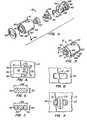
- FIG. 3is a perspective view of the attachment mechanism of the first embodiment
- FIG. 4is an exploded view of the attachment mechanism of FIG. 3 ;
- FIG. 5is a fragmentary elevation view of a slot in a piece of equipment specially designed to accept the attachment mechanism of either embodiment of the present invention
- FIG. 6is a section view taken along lines 6 — 6 of FIG. 3 ;
- FIG. 7is a section view taken along lines 7 — 7 of FIG. 3 ;
- FIG. 8is a fragmentary section view from inside an item of equipment illustrating insertion of a crossmember of the embodiment of FIG. 3 into the slot of FIG. 5 ;
- FIG. 9is a view similar to that of FIG. 8 with the crossmember misaligned
- FIGS. 10A and Bare elevation views illustrating the installation of the attachment mechanism of FIG. 3 on an item of equipment
- FIG. 11is a perspective view of the attachment mechanism of the second embodiment of the present invention.
- FIG. 12is an exploded view of the attachment mechanism of FIG. 10 ;
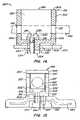
- FIGS. 13A and 13Bare side elevation views illustrating the installation of the attachment mechanism of FIG. 11 on an item of equipment;
- FIGS. 14 and 15are side elevational views of alternative embodiments of an attachment mechanism and an engagement mechanism
- FIGS. 16A and 16Bare respective perspective views of another alternative embodiment of an attachment mechanism and an engagement mechanism of the invention.
- FIG. 16Cis a side elevational view of the attachment mechanism and the engagement mechanism of FIGS. 16A and 16B assembled together proximate the external wall of an item of equipment;
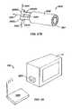
- FIG. 17Ais a side elevational view of another embodiment of the invention.
- FIG. 17Bis a corresponding perspective view of the embodiment of FIG. 17A ;
- FIG. 18is a side elevational view of a slightly modified version of the embodiment of FIGS. 17A and 17B showing a threaded engagement between the spindle and the housing;
- FIG. 19is a perspective view of another slightly modified version of the embodiment of FIGS. 17A and 17B showing a pin and pin hole engagement between the attachment mechanism and the external wall of an item of equipment;
- FIG. 20is a perspective view of another embodiment of the invention having two engagement portions
- FIGS. 21A , 21 B, and 21 Care perspective views of component parts of another embodiment of the invention showing a separate attachment mechanism, housing, and engagement mechanism respectively;
- FIG. 21Dis perspective view of the embodiment of FIGS. 21A , 21 B, and 21 C showing the three component parts in an assembled configuration
- FIGS. 22A and 22Bare perspective views of component parts of another embodiment of the invention showing an engagement mechanism and a separate attachment mechanism respectively;
- FIG. 22Cis a side elevational view of the embodiment of FIGS. 22A and 22B with the engagement mechanism coupled to the attachment mechanism;
- FIGS. 23A and 23Bare perspective views of slightly modified version of the respective component parts of FIGS. 22A and 22B ;
- FIG. 23Cis a side elevational view of the embodiment of FIGS. 23A and 23B with the attachment mechanism shown coupled to a slot in the external wall of an item of equipment;
- FIG. 24Ais a side elevational view of an attachment mechanism coupled to an engagement mechanism according to another embodiment of the invention.
- FIG. 24Bis a perspective view of the embodiment of FIG. 24A with the attachment mechanism and engagement mechanism shown coupled to a cable and a separate locking device;
- FIG. 25Ais a perspective view of the attachment mechanism of FIGS. 24A and 24B which can be directly coupled to an external wall of an item of equipment;
- FIG. 25Bis a perspective view of another embodiment of the attachment mechanism of FIGS. 24A and 24B which can be directly coupled to an external wall with the use of an adhesive;
- FIG. 26is another embodiment of an attachment mechanism which can be directly coupled to an external wall of an item of equipment
- FIG. 27Ais a perspective view of another embodiment of the present invention with a conventional lock assembly and a retractable spindle;
- FIG. 27Bis a perspective view of the spindle and lock assembly of FIG. 27A showing the spindle in its retracted position;
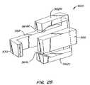
- FIG. 28is a perspective view of a bracket assembly which can be used with the device of the embodiment of FIG. 20 to permanently lock the device to an item of equipment;
- FIG. 29is perspective view of another embodiment of the preferred embodiment including a base unit and an attachment unit.
- Security device 10includes an attachment mechanism 12 designed to attach to a component of a computer system, such as computer monitor 14 .
- Attachment mechanism 12has an aperture 16 , and a cable 18 which passes through the aperture when the attachment mechanism 12 is attached to a component such as monitor 14 .
- a lock 20is fixed to one end of cable 18 .
- the free end of cable 18may be of the type having a “mushroom” head 22 adapted to penetrate and be secured within lock 20 using key 24 .
- mushroom head 22detached from lock 20 , cable 18 can be threaded through the apertures 16 of one or more attachment mechanisms 12 , and wrapped around a relatively immovable object (not shown) such as the cross bar spanning two legs of a desk. Mushroom head 22 is then inserted into lock 20 and the lock closed using key 24 to secure the computer components to the immovable object.
- Embodiment 26includes an attachment mechanism 28 designed to be secured to a computer component such as keyboard 30 .
- Attachment mechanism 28is affixed to one end of a cable 32 which has a closed loop 34 at its other end. Cable 32 is first wrapped around a relatively immovable object, such as a cross piece between two legs of a desk or table, and attachment mechanism 28 is passed through loop 34 and attached to the item to be protected such as keyboard 30 to make it difficult to steal the item of equipment.
- Mechanism 12includes a housing 36 having a hollow interior cylindrical cavity 38 .
- An annular plate 40forms one end of housing 36 and has an aperture 41 .
- a pair of apertures such as aperture 16are located on opposite sides of housing 36 .
- a small raised aperture 42is also provided in housing 36 to accommodate a pin 44 , as explained in more detail hereinafter.
- a spindle 46includes a cylindrical portion 48 adapted to fit within the cylindrical cavity of housing 36 .
- Spindle 48includes a raised plate 50 at one end which forms the aft end of the mechanism when assembled as illustrated in FIG. 3 .
- Spindle 46also includes a shaft 52 extending outwardly through the aperture 41 in housing 36 .
- a crossmember 54is located on the distal end of shaft 52 .
- An abutment mechanism 56includes an abutment plate 58 designed to be received within the cylindrical interior cavity of housing 36 , and a pair of pins 60 adapted to extend outwardly through the aperture 41 in housing 36 .
- a spring 62biases abutment plate 58 and spindle 46 rearwardly when the mechanism is assembled, as illustrated in FIG. 3 .
- a plastic bushing 64designed to prevent scarring of the equipment to which mechanism 12 is attached is affixed to the plate 40 on housing 36 circumscribing aperture 41 .
- crossmember 54 and shaft 52together with pins 60 on either side of the shaft, extend outwardly beyond housing 46 through aperture 41 .
- Pin 44engages a groove 66 in spindle 46 so that the mechanism cannot be disassembled without removing the pin.
- the head of pin 44is conformed to the shape of a boss 67 on the surface of housing 36 so that the pin cannot be removed without special equipment.
- Groove 66has a preselected width allowing limited axial movement of spindle 46 relative to housing 36 with pin 44 engaged so that the axial position of crossmember 54 relative to the housing is somewhat adjustable.
- Spring 62biases plate 58 and spindle 46 rearwardly to bias crossmember 54 toward housing 36 .
- Groove 66extends around about 25% of the periphery of spindle 46 so that the spindle can be rotated approximately 90° relative to the housing.
- a transverse aperture 68 through the cylindrical portion 48 of spindle 46is aligned with aperture 16 in housing 36 when crossmember 54 is misaligned from pin 60 (see FIG. 4 ). With spindle 46 rotated 90°, as allowed by pin 44 in groove 68 , crossmember 54 is aligned with pin 60 , and aperture 68 is not aligned with aperture 16 . Cable 18 (see FIG.
- the preferred embodiments 10 and 26 of the present inventionare designed to operate with items of equipment provided by a special slot, as illustrated in FIG. 5 .
- the exterior wall 70 of the piece of equipmentis typically made of sheet metal, or molded plastic, either of which is compatible with the present invention.
- a relatively small slot 72is formed in wall 70 , by molding or otherwise as appropriate.
- the slothas a generally rectangular configuration, i.e., the slot is generally rectangular having long parallel sides 74 , short parallel sides 75 and rounded corners 76 .
- Slot 72is relatively small, having a long dimension 78 of seven millimeters, and a short dimension 79 of three millimeters, in the preferred embodiment of the present invention. Corners 76 have a radius of curvature 90 from 0.30 mm. to a maximum of 1.5 millimeters. If the radius of curvature 90 is 1.5 mm., the short sides 75 disappear and the slot has a straight-sided oval configuration.
- crossmember 54The peripheral dimensions of crossmember 54 are closely conformed to the interior dimensions of slot 72 , as illustrated in FIG. 6 .
- the crossmember 4 of attachment mechanism 12has a straight-sided oval configuration, i.e., the crossmember is generally rectangular, having straight sides and semi-circular ends.
- the long dimension 82 of crossmember 54is 6.75 millimeters
- the short dimension 83is 2.75 millimeters, each being slightly less than the corresponding dimension of slot 72 .
- the peripheral dimensions of the pins 60 and shaft 52also closely conform to the interior dimensions of slot 72 .
- pins 60 in shaft 52have a long dimension 84 of 6.75 millimeters, and a short dimension 85 of 2.75 millimeters.
- crossmember 54 of attachment mechanism 12is illustrated by reference to FIGS. 8 and 10A .
- spindle 46Before insertion, spindle 46 must be rotated so that crossmember 54 is aligned with pins 60 , as illustrated in FIG. 3 . With the spindle in this position, the periphery of crossmember 54 and that of pins 60 and shaft 52 are essentially congruent. Since the peripheral dimension of crossmember 54 and pins 60 and shaft 52 in combination are less than the dimensions of slot 72 , the crossmember can be inserted through the slot until crossmember 54 is completely inside wall 70 (see FIG. 10A ). If necessary, the plate 50 on spindle 46 can be pressed to compress spring 62 so that crossmember 54 is completely inside wall 70 .
- Attachment mechanism 28includes a hollow shell 90 and a nose-piece 92 which, in combination, form a housing.
- Shell 90has a hollow cylindrical interior cavity 94 , and an integral apertured plate 96 at one end.
- a pin 98is inserted through an aperture (not shown) in nose-piece 92 to engage a slot 102 in shell 90 .
- Pin 98is designed to shear when torque is applied to nose-piece 92 so that an unauthorized attempt to remove the attachment mechanism will simply shear the pin and allow the nose-piece to freely rotate without degrading the attachment of the attachment mechanism to the component to be protected.
- Slot 102is axially elongate so that limited axial movement is allowed between shell 90 and nose-piece 92 .
- the forward end of nose-piece 92has a plate 93 having a central aperture 95 .
- a cylindrical collar 106circumscribes the outer portion of shell 90 and occupies the slot laterally defined by plate 96 and the aft surface 108 of nose-piece 92 .
- Collar 106has an integral tab 110 with an aperture 112 adapted to receive one end of cable 32 . Cable 32 is dead-ended into tab 110 and attached so that it cannot be removed.
- a spindle 114has a cylindrical portion 116 adapted to be received within a cylindrical lock 118 in shell 90 .
- Cylindrical lock 118includes a front cylinder 119 , and a back cylinder 120 .
- a blunt pin or set screw 121is inserted through an aperture 125 in shell 90 , and through a corresponding aperture 123 in back cylinder 120 , to lock the front cylinder rotationally with respect to shell 90 .
- pin or set screw 127engages a relatively smaller aperture 129 in front cylinder 119 , and a widening 131 in slot 133 in the cylindrical portion 116 of spindle 114 .
- Front cylinder 119is thus fixed rotationally with respect to spindle 114 .
- a plurality of pinsnormally span the interface between front cylinder 119 and back cylinder 120 so that the cylinders are rotationally locked together, thus preventing relative rotation between locking shell 90 and spindle 114 .
- a key 140(see FIG. 13B ) is insertable through the apertured plate 96 of shell 90 to engage front cylinder 119 .
- the correct keywill have bosses located to depress the pins passing between cylinders 119 and 120 so that such pins do not span the interface between the cylinders, allowing the cylinders to rotate with respect to one another. In this fashion, spindle 114 can be rotated with respect to shell 90 only upon insertion and rotation of the appropriate key.
- Spindle 114also includes a shaft 122 , and a crossmember 124 at the free end of the shaft.
- An abutment mechanism 126has an abutment plate 128 adapted to fit within nose-piece 92 , and a pair of pins 130 adapted to extend outwardly through aperture 95 .
- a spring 132is located between abutment plate 128 and nose-piece 92 to bias the cylindrical portion 116 of spindle 114 and the abutment plate rearwardly.
- Abutment plate 126has an elongate aperture 134 which allows crossmember 124 to extend through the aperture plate.
- a plastic bushing 136is fixed to the surface of plate 93 so that the mechanism does not scar the equipment to which it is attached.
- FIGS. 13 A and BThe insertion of attachment mechanism 28 into the exterior wall 137 of a piece of equipment is illustrated by way of reference to FIGS. 13 A and B.
- Wall 136has a slot 138 , which is identical to the slot 72 illustrated in FIG. 8 .
- the peripheral dimensions of crossmember 124 , and also those of pins 130 and shaft 122 in combination,are identical to the corresponding parts in FIGS. 6 and 7 .
- attachment mechanism 28is designed to fit into the same slot as attachment mechanism 12 .
- crossmember 124is aligned with pins 30 so that the crossmember can be inserted into slot 138 .
- the space in the slotis essentially occupied by pins 130 and shaft 122 .
- plate 96can be depressed to push the cylindrical portion 116 of spindle 114 against spring 132 .
- a key 140 engaging lock mechanism 118is used to rotate the spindle 900 and misalign crossmember 124 and slot 138 .
- both attachment mechanism 12 and attachment mechanism 28are attached to an item of computer or other equipment which has a specially designed slot 72 , 138 .
- First the crossmember 54 , 124is aligned with the pins 60 , 130 , for insertion to the crossmember through the slot.
- the spindle 46 , 114is then rotated relative to the housing to misalign the crossmember 54 , 124 relative to the slot.
- the spindleis locked in this configuration by passing the cable 18 through the mating slot 16 , 48 in the first embodiment, or using the key 140 in the second embodiment. Either way, the attachment mechanism is extremely difficult to disengage by anyone not having the appropriate key 24 , 140 . Any unauthorized attempt to remove the attachment mechanism from the computer component will most likely result in significant damage to the computer housing, making the computer difficult to resell and greatly reducing its theft potential.
- FIG. 14illustrates another embodiment of the invention.
- Security device 200includes an attachment mechanism 201 designed to be attached to a portable object of equipment, such as a personal computer (not shown), having an external wall 250 .
- Attachment mechanism 201comprises a housing 202 which generally includes a top end 204 , a bottom end 208 , and a generally cylindrical side wall 206 , which in combination define internal hollow cavity 210 .
- Side wall 206has a pair of apertures 212 which are aligned with one another and which are sized to allow a cable 242 to pass through the apertures.
- Top end 204is provided with an opening 214 which extends to proximate bottom end 208 to provide access for screw 230 into cavity 210 , as will be described in more detail hereinafter.
- a raised plate 218 having a threaded aperture 216is provided in bottom end 208 of the housing to accommodate insertion of screw 230 .
- an engagement mechanism 220Integral with bottom end 208 of housing 202 is an engagement mechanism 220 which includes a generally cylindrical shaft 222 and a crossmember 224 attached to the shaft at the distal end of the shaft. As previously described with reference to prior embodiments of the invention, the peripheral dimensions of the crossmember conform closely to the internal dimensions of slot 252 .
- the crossmember 224is generally rectangular, having straight sides and semi-circular ends, as previously described.
- housing 202To secure attachment mechanism 201 proximate external wall 250 , housing 202 must first be rotated prior to insertion of screw 230 so that crossmember 224 is aligned with slot 252 . Since the peripheral dimensions of crossmember 224 and shaft 222 are less than the dimensions of slot 252 , crossmember 224 can be inserted through the slot until the crossmember is completely inside external wall 250 , with shaft 222 occupying a portion of slot 252 . Housing 202 may then be rotated by grasping onto side wall 206 and turning housing 202 until crossmember 224 is 90 degrees misaligned with respect to the slot. In this position of the crossmember, screw 230 can be inserted through opening 214 in the housing and threaded into aperture 216 in raised plate 218 of the housing.
- screw portion 234 and shaft 222occupy slot 252 when the screw is threadably engaged with aperture 216 in the housing so as to prevent rotation of the housing relative to the external wall and thereby prevent disengagement of crossmember 224 from slot 252 .
- cable 242can easily be threaded through apertures 212 to secure the housing to an external object (not shown). Once the cable is inserted through apertures 212 in the housing, screw 230 cannot be removed.
- FIG. 15illustrates another embodiment of the invention which has a similar configuration to the embodiment of FIG. 14 except that a spindle 260 is used instead of a screw to prevent rotation of housing 202 ′.
- Spindle 260includes a cylindrical portion 264 adapted to be rotatably mounted within the cylindrical cavity 210 ′ of the housing.
- An aperture 268is formed through cylindrical portion 264 and is sized to allow a cable (not shown) to pass through the aperture.
- Spindle 260includes a raised plate 266 at a proximal end of the spindle which forms the aft end of the spindle.
- Spindle 260also includes a pin member 270 extending outwardly through aperture 216 ′ in housing 202 ′. The length of the pin member 272 external the housing is slightly greater than the thickness of external wall 250 .
- spindle 260is positioned in the housing so that base pin 270 is inserted through aperture 216 ′ and into slot 252 proximate shaft 222 ′.
- the peripheral dimension of the shaft and the pin in combinationis less than the dimension of the slot so that the pin and shaft occupy the slot with the crossmember misaligned 90 degrees.
- spindle 260is rotated by manipulating raised plate 266 so that apertures 212 ′ in the sidewall 206 ′ of housing 202 ′ will be aligned with aperture 268 in cylindrical portion 264 of the spindle, providing a passageway completely through the housing.
- a cable(not shown) can easily be threaded through the apertures, and the presence of the cable prevents spindle 260 from being separated from the housing.
- FIGS. 16A , 16 B and 16 Cillustrate another embodiment of the invention in which the attachment mechanism 300 is a separate component from the engagement mechanism 320 .
- Attachment mechanism 300comprises a housing 302 having a top end 304 , a bottom end 308 , spaced apart side walls 306 , and a peripheral edge wall 309 , as seen in an inverted configuration in FIG. 16A .
- Bottom end 308includes a generally rectangular opening 310 which extends the length of the housing to closed top end 304 . Opening 310 is configured to permit passage of engagement mechanism 320 into housing 302 , as will be described in more detail hereinafter.
- Apertures 312 through side wall 306are spatially coupled to opening 310 and are sized to allow a cable (not shown) to pass through the apertures.
- Housing 302also preferably includes first and second springs 316 L and 316 R mounted on either side of bottom end 308 of the housing which are used to adjust the relative position of the housing proximate the external wall 350 , as best seen in FIG. 16C .
- Housing 302further includes first and second, spaced apart abutment plates 314 L and 314 R located on opposite sides of opening 310 .
- Engagement mechanism 320which is configured to fit within housing 302 through opening 310 , is shown by way of reference to FIG. 16B and generally includes a spindle 322 .
- Spindle 322has an upper portion 324 which includes aperture 326 sized to permit passage of a cable (not shown) through aperture 326 .
- a shaft 328Connected to the distal end of upper portion 324 of the spindle is a shaft 328 which has generally rectangular crossmember 330 attached to the shaft at the distal end of the shaft. The dimensions of the crossmember conform closely to the dimensions of the slot 352 , as previously described.
- Engagement mechanismalso preferably includes a spring 332 located around the periphery of shaft 328 .
- crossmember 330is aligned with slot 352 and is inserted therein until crossmember 330 is completely inside external wall 350 , as seen in FIG. 16C . If necessary, the upper portion 324 of spindle 322 can be firmly pressed to compress spring 332 so that crossmember 330 is completely inside wall 350 .
- spindle 322Upon insertion of crossmember 330 completely through slot 352 , spindle 322 is rotated so that crossmember 330 is 90 degrees misaligned with slot 352 .
- housing 302is placed over the spindle 322 , so that the spindle is received within opening 310 in the housing.
- Abutment plates 314 L and 314 Rare inserted into the slot on both sides of shaft 328 extending from spindle 322 . With the upper portion 324 of the spindle completely received within the housing, aperture 326 in spindle 322 will be aligned with apertures 312 in housing 302 , providing a passageway completely through the housing.
- a cable(not shown) can be easily threaded through the apertures, and the presence of the cable secures the spindle to the housing.
- the peripheral dimension of the abutment plates 314 L, 314 R and shaft 328 of the spindle in combinationclosely conform to the dimensions of the slot and thereby occupy the slot.
- the housingis fixed relative to the spindle and neither can be rotated back so as to disengage crossmember 330 from slot 352 .
- Springs 316 L, 316 Rare biased against the lower end of the housing to firmly secure housing 302 proximate the external wall 350 .
- Attachment mechanism 400comprises housing 402 which generally includes top end 404 , bottom end 406 , and cylindrical side wall 408 , which in combination define internal cylindrical cavity 409 .
- a cylindrical opening 412 in the top end 404 of the housingextends to proximate closed bottom end 406 of the housing and is configured to allow engagement mechanism 420 to be rotatably mounted within the housing.
- Side wall 408has a pair of apertures 410 which are sized to allow passage of a cable (not shown) through the apertures.
- abutment plates 414 L and 414 RAttached to bottom end 406 of the housing are two abutment plates 414 L and 414 R which are spaced apart from aperture 416 in bottom end 406 and which are adapted to be inserted into slot 452 in external wall 450 (See FIG. 17B ).
- Spindle 420includes a cylindrical portion 424 rotatably mounted within the cylindrical cavity 409 of housing 402 .
- Spindle 420includes a raised plate 423 at one end which forms the aft end of the spindle.
- Spindle 420also includes a shaft 428 extending outwardly through aperture 416 in housing 402 .
- a crossmember 430is located at the distal end of shaft 428 .
- Aperture 426 through cylindrical portion 424 of the spindle 420is sized to allow a cable (not shown) to pass through aperture 426 .
- a spring 440is located at the distal end of cylindrical portion 424 of the spindle and biases the spindle away from the bottom end of housing 402 so that crossmember 430 will firmly engage the inner surface of external wall 450 , as will now be described.
- crossmember 430 and shaft 428together with abutment plates 414 L and 414 R on either side of the shaft, extend outwardly beyond the bottom end 406 of housing 402 .
- spindle 420Prior to insertion of crossmember 430 into slot 452 , spindle 420 must be rotated via raised plate 423 so that crossmember 430 is aligned with slot 452 , as seen in FIG. 17B . With the spindle in this position, the crossmember can be inserted through the slot as previously discussed. If necessary, plate 423 can be pressed to compress spring 440 so that crossmember 430 is completely inside wall 450 . In this position of the crossmember, shaft 428 and abutment plates 414 L, 414 R occupy the slot to prevent rotation of the housing relative to external wall 450 .
- Side wall 408 of housing 402preferably includes at least one small hole 411 on either side of the housing through which a pin 460 engages a groove (not shown) in the cylindrical portion 424 of the spindle, the groove extending around about 25% of the periphery of cylindrical portion 424 so that the spindle can be rotated substantially only 90 degrees relative to the housing.
- apertures 410 in the side wall of housing 402will be aligned with aperture 426 in the spindle providing a passageway completely through the housing.
- a cable(not shown) can easily be threaded through the aligned apertures, and the presence of the cable prevents the spindle from being rotated back so as to disengage crossmember 430 from slot 452 .
- FIGS. 17A and 17Bcan be slightly modified to provide a threaded cylindrical portion 424 ′ of the spindle 420 ′, as seen in FIG. 18 .
- the internal peripheral surface 413 of side wall 408 ′is also threaded so that the cylindrical portion 424 ′ engages threaded surface 413 .
- This engagement variation between spindle 420 ′ and housing 402 ′can be used instead of spring 440 in FIG. 17A to adjust the relative lateral displacement between the spindle and the housing.
- FIG. 19illustrates another alternative embodiment of a housing 402 ′′ which is used to prevent rotation of the housing relative to the external wall 450 when the crossmember is misaligned with the slot.
- pins 472are mounted to the outer surface of the external wall on either side of slot 452 and engage pin holes 470 located on opposite sides of shaft 428 ′′ to prevent rotation of the housing relative to external wall 450 when crossmember 430 ′′ is located completely within slot 452 and is misaligned from the slot.
- FIGS. 20–23wherein the engagement mechanism includes at least two engagement portions for engaging with the inner surface of the external wall proximate the slot to prevent removal of the attachment mechanism from proximate the external wall.
- a single body device 500is shown mounted proximate external wall 550 which generally includes an attachment mechanism 501 comprising attachment member 502 .
- Attachment member 502broadly includes a closed top end 504 , a bottom end 506 , an outer peripheral edge wall 509 , and spaced apart side walls 508 .
- Side walls 508have an aperture 510 therethrough which is sized to permit a cable (not shown) to pass through the aperture.
- Engagement mechanism 520is integral with bottom end 506 of attachment member 502 and generally includes engagement member 522 .
- Engagement member 522is preferably made from a resilient plastic material as is conventional in the art so that it can bend inward to fit within slot 552 and then spread back to a position within the slot in which engagement portion 524 engages the inner surface of external wall 550 proximate the slot.
- Engagement member 522includes a shaft 528 and a base portion 524 connected to the distal end of shaft 528 .
- Base portion 524includes spaced apart side walls 526 L, 526 R on opposite sides of base portion 524 . Side walls 526 L, 526 R are inwardly angled so as to facilitate access into slot 552 .
- a userfirmly grasps side walls 508 of attachment member 502 and pushes downwardly so that side walls 526 L, 526 R of base portion 524 will engage slot 552 and bend slightly inward to fit within the slot.
- resilient side walls 526 L, 526 Rwill flex back to their natural configuration to thereby engage the inner surface of external wall 550 proximate the slot. In this configuration, the housing will be prevented from moving relative to the external wall.
- a cable(not shown) may then be inserted through aperture 510 to secure the attachment mechanism 501 to an immovable object (not shown).
- Bracket assembly 560generally includes first and second, spaced apart resilient arms 562 R and 562 L on either side of the assembly having first and second, inwardly angled flanges 564 R, 564 L at the distal end of the arms.
- a pair of brackets 566 and 568form the front and back end of assembly 560 and are used to guide device 500 into the bracket assembly.
- Bracket 568has a rear flange 570 at the distal end of bracket 568 which forms a rear stop for device 500 when inserted into the bracket assembly 566 .
- base portion 524 of device 500is inserted into bracket assembly 560 until side walls 526 L, 526 R engage with flanges 564 L, 564 R respectively.
- side walls 526 L and 526 Rwill cause flanges 564 L and 564 R to flex apart slightly so as to permit movement of base portion 524 past the flanges.
- Movement of device 500is subsequently limited by engagement of the bottom of base 524 with rear flange 570 . In this position, removal of device is prevented by engagement of the upper surface of base 524 with the lower surfaces of flanges 564 R and 564 L.
- FIGS. 21A , 21 B, 21 C and 21 Dillustrate another embodiment of the invention 600 including three separate components, an attachment mechanism 602 (see FIG. 21A ), a housing 620 (see FIG. 21B ), and a separate engagement mechanism 640 (see FIG. 21C ).
- Attachment mechanism 602includes attachment member 603 shown in an inverted position in FIG. 21A .
- Attachment member 603generally includes a top end 604 , a bottom end 606 , spaced apart side walls 608 , and a peripheral edge wall 609 .
- An aperture 610is provided through side walls 608 and is sized to permit passage of a cable (not shown) through aperture 610 .
- Base portion 612is integrally connected to attachment member 603 proximate bottom end 606 of the attachment member.
- a retaining flange 614is provided proximate top end 604 to retain attachment member 603 within housing 620 , as will be described in more detail hereinafter.
- Housing 620is shown by way of reference to FIG. 21B and generally includes a top wall 622 , a bottom wall 624 , and four separate spaced apart side walls including a front end 626 and a back end 628 .
- a pair of substantially rectangular openings 632are provided through both top wall 622 and bottom wall 624 of the housing and are configured to allow passage of the attachment member 603 through openings 632 .
- a separate, generally rectangular aperture 630is provided in front end 626 of housing 620 and extends the length of the housing to the closed back end 628 .
- Aperture 630is configured to permit passage of engagement mechanism 640 into the aperture, as will be described in more detail hereinafter.
- Bottom wall 624is also provided with a pin hole 636 proximate front end 626 which is sized to receive a retaining pin 634 therein.
- the housingis preferably made from cast metal, but any other suitable material may be used.
- Engagement mechanism 640is shown by way of reference to FIG. 21C and includes an engagement member 642 .
- Engagement member 642includes first and second, spaced apart engagement arms 646 L, 646 R which have first and second engagement portions 648 L, 648 R integrally connected to the arms at the distal end of arms 646 L, 646 R.
- a transverse member 644connects the two engagements arms 646 L, 646 R together at the proximal end of the arms and defines an abutment surface 645 located towards the distal end of transverse member 644 .
- Engagement arms 646 L, 646 R and transverse member 644in combination define clearance space 649 which is sized to permit passage of attachment member 603 through clearance space 649 , as will now be described.
- engagement member 642is initially inserted into rectangular aperture 630 in housing 620 until transverse member 644 abuts against back end 628 of the housing.
- Retaining pin 634is subsequently inserted into pin hole 636 in the housing and secured thereto so that engagement member 642 cannot be removed from the housing without removing the pin.
- Attachment member 603is then inserted into rectangular openings 632 in the housing and through clearance space 649 of the engagement member so that the attachment member extends outwardly through opening 632 in bottom wall 624 of the housing.
- Base portion 612 of the attachment memberengages the upper surface of top wall 622 of the housing to prevent passage of attachment member 603 completely through housing 620 .
- Retaining flange 614prevents attachment member 603 from being separated from the housing.
- abutment surface 645 of transverse member 644engages with attachment member 603 to secure engagement member 642 to attachment member 603 .
- engagement portions 648 L, 648 R and a lower portion of engagement arms 646 L, 646 Rextend outwardly beyond front end 626 of housing 620 .
- engagement portions 648 L, 648 Rmay be pressed firmly against slot 652 until the engagement portions bend sufficiently inward to fit within slot 652 .
- the inwardly sloped peripheral dimensions of the engagement portionspermit easier access into slot 652 .
- engagement portions 648 L, 648 RUpon insertion of engagement portions 648 L, 648 R completely within the slot, with a portion of the engagement arms 646 L, 646 R occupying the slot, the arms will spread back to their natural configuration and thereby engage the internal surface of the external wall 650 proximate slot 652 to secure the device 600 proximate the external wall.
- a cable(not shown) can then be inserted through aperture 610 in attachment member 603 , and the presence of the cable prevents the attachment member 603 from moving relative to housing 620 .
- FIGS. 22A , 22 B, and 22 Cdepict another embodiment of the invention, device 700 , in which there are two major component parts, attachment mechanism 701 and engagement mechanism 720 .
- Attachment mechanism 701 of FIG. 22Bgenerally includes an attachment member 702 having a closed top end 704 , a bottom end 706 , a peripheral edge wall 709 , and spaced apart side walls 708 .
- An aperture 710is provided through side walls 708 and is sized to permit a cable to pass through aperture 710 .
- a generally rectangular opening 712is further provided in bottom end 706 of attachment member 702 and extends the length of the attachment member to closed top end 704 . Opening 712 is configured to accommodate passage of the engagement mechanism 720 into opening 712 , as will be described in more detail hereinafter.
- Engagement mechanism 720is shown by way of reference to FIG. 22A and generally includes engagement member 722 having first and second, spaced apart engagement arms 724 L and 724 R connected at the proximal end of engagement member 702 and defining a clearance space 725 between the arms sized large enough to permit a cable to pass through clearance space 725 .
- Abutment surface 730is located adjacent the proximal end of the engagement arms.
- Engagement portions 726 L, 726 Rare integral with engagement arms 724 L, 724 R at the distal end of the arms.
- a pair of grooves 728is provided in engagement portions 726 L, 726 R, with the length of the groove being substantially equal to the thickness of external wall 750 (See FIG. 22C ).
- Engagement member 722is preferably injection molded and made from a plastic material to enhance its resiliency.
- the engagement membermay be made from other materials, such as metal, provided that the material is sufficiently resilient to allow engagement arms 724 L, 724 R to be bent inward sufficiently far enough to allow engagement portions 726 L, 726 R to be inserted into slot 752 .
- engagement arms 724 L, 724 Rare pressed towards one another so that engagement portions 726 L, 726 R are positioned sufficiently close to one another to allow the engagement portions to be inserted into slot 752 .
- grooves 728engage with external wall 750 when engagement portions 726 L, 726 R are within slot 752 and have spread back to their natural configuration.
- engagement member 722is firmly secured to external wall 750 .
- attachment member 702is positioned over engagement member 722 until clearance space 725 is aligned with aperture 710 in the housing.
- a cable 740can easily be threaded through aperture 710 in the housing and clearance space 725 , and the presence of the cable 740 prevents attachment member 702 from being separated from engagement member 722 .
- FIGS. 23A , 23 B, and 23 Cillustrate a slightly modified version of the embodiment of FIGS. 22A , 22 B, and 22 C.
- housing 702 ′preferably includes a retaining pin hole 714 .
- Engagement mechanism 720 ′is also slightly modified to include a retaining pin 734 which engages with pin hole 714 proximate bottom end 706 ′ of housing 702 ′ to prevent engagement member 722 ′ from being separated from housing 702 ′ prior to insertion of a cable (not shown).
- Engagement member 722 ′ of FIGS. 23A and 23Cis adapted to engage with a slot having substantially smaller peripheral dimensions than the slot necessary to engage with engagement member 722 of FIG. 22A .
- FIGS. 24A and 24Billustrate another embodiment of the invention 800 in which there are also substantially only two component parts, an attachment mechanism 801 and an engagement mechanism 820 .
- Attachment mechanism 801shown by way of reference to FIG. 24A , generally includes an attachment member 802 having a top end 804 , a bottom end 806 , and a cylindrical side wall 808 .
- a pair of apertures 810are provided through side wall 808 and are sized to permit a cable 840 to pass through apertures 810 (See FIG. 24B ).
- a generally cylindrical opening 812is further provided in top end 804 of attachment member 802 and extends the length of the attachment member to a substantially smaller screw opening 814 in bottom end 806 of the attachment member. Opening 812 is configured to accommodate passage of screw 816 through opening 812 to bottom end 806 of the attachment member, as will be described in more detail hereinafter.
- Engagement mechanism 820is used in conjunction with attachment member 802 , as is also illustrated in FIG. 24A .
- Engagement mechanism 820generally includes engagement member 822 having first and second, spaced apart engagement arms 824 L and 824 R connected to base portion 830 at the proximal end of engagement member 822 and defining a clearance space 825 between the arms sized large enough to permit screw 816 to pass through clearance space 825 .
- Base portion 830has a top surface 833 and a bottom surface 831 and is provided with a screw hole 832 through the surfaces.
- Engagement portions 826 L, 826 Rare integral with engagement arms 824 L, 826 R at the distal end of the arms.
- engagement portions 826 L, 826 Rhave inwardly sloped side walls which facilitate insertion of the engagement portions into slot 852 , as previously described.
- engagement portions 826 L, 826 Rare inserted into slot 852 until lower surface 831 of base portion 830 engages the outer surface of external wall 850 .
- attachment member 802is positioned proximate upper surface 833 of base portion 830 until screw hole 832 is aligned with opening 814 in the attachment member.
- Screw 816is then inserted through each of opening 812 in the attachment member, opening 814 at the bottom end 806 of the housing, hole 832 in base portion 830 , and clearance space 825 .
- the screwwill force engagement arms 824 L, 824 R to spread apart so that engagement portions 826 L, 826 R will engage the inner surface of external wall 850 proximate slot 852 .
- cable 840(See FIG. 24B ) can be threaded through apertures 810 in the attachment member and attached to an external object, such as lock 860 , to secure the attachment member to the lock.
- the cablewill also prevent removal of screw 816 .
- an attachment member 802 ′can be used independently of engagement mechanism 820 provided that an appropriate screw hole or screw insert is provided in the external wall (not shown) sized to permit screw 816 ′ to engage with the hole (or insert), as is apparent from FIG. 25A .
- an attachment member 802 ′′may also be secured to an external wall by any other suitable engagement means, as for example providing a double-sided adhesive pad 870 for engaging both the bottom end of the attachment member 802 ′′ and the outer surface of the wall (not shown), as seen in FIG. 25B .
- attachment member 802 ′′′can be hingably connected to a base portion 818 having a screw hole 814 ′′′ so that the attachment member 802 ′′′ will swing away from the external wall when not in use, as seen in FIG. 26 .
- base portion 818may be secured proximate the external wall of an item of equipment via screw 816 ′′′ and a threaded insert 819 .
- FIGS. 24A and 24Bcan also be modified to include a conventional lock assembly 910 (as previously described by way of reference to the embodiment of FIG. 2 ) in combination with a retractable spindle arm 908 .
- attachment mechanism 900is affixed to one end of a cable 920 which has a closed loop 922 at its other end. Cable 920 is first wrapped around a relatively immovable object (not shown) and attachment mechanism 900 is passed through loop 922 and attached to the item to be protected such as external wall 950 to make it difficult to steal.
- Attachment mechanism 900is shown in its retracted position in FIG. 27B and generally includes a housing 902 and first and second, resilient engagement arms 904 L and 904 R which are mounted to the bottom end of housing 902 and extend outwardly therefrom.
- Engagement arms 904 L, 904 Rhave first and second, inwardly angled engagement portions 906 L and 906 R at the distal end of each of the arms which are configured so as to be easily received within slot 952 in the retracted position of spindle arm 908 , as will be described in more detail hereinafter.
- a conventional cylindrical lock assembly 910At the other end of housing 902 from the engagement arms is a conventional cylindrical lock assembly 910 , an example of which was described in detail by reference to FIG. 13B .
- a spindle arm 908is adapted to be mounted to cylindrical lock assembly 910 at one end, with the opposite end of arm 908 extending between engagement arms 904 L and 904 R external of housing 902 .
- Spindle arm 908is connected to lock assembly 910 in such a manner that rotation of lock assembly 910 with an appropriate key (not shown) will cause translational movement of spindle arm 908 in the direction of arrow 930 (see FIG. 27B ).
- This movement of arm 908can be accomplished in any manner as is well known in the art, as for example having spindle arm 908 received within a corkscrew shaped cam attachment mounted to lock assembly 910 so that rotation of the lock will cause corresponding translational movement of spindle arm 908 .
- engagement portions 906 L and 906 Rare insertable into slot 952 .
- a keycan be inserted into lock assembly 910 and rotated so that spindle arm 908 will be moved in the direction of arrow 930 to its extracted position.
- the movement of spindle arm 930 along arrow 930permits engagement arms 904 L and 904 R to flex outwards in the direction of arrow 940 so that engagement portions 906 L and 906 R will move outwards to engage the inner surface of slot 952 .
- attachment mechanism 900will be secured proximate external wall 950 .
- FIG. 29is a perspective view of an alternate preferred embodiment of the present invention.
- Proximity detecting system 980includes a base unit 982 and a remote unit 984 relatively permanently attached to monitor 14 by use of a standardized slot 72 (as shown in FIG. 5 for example).
- the various embodiments shown in FIGS. 1–28provide examples of different attachment schemes for remote unit 984 .
- Base unit 982 and remote unit 984operate together to control a separation distance between them.
- proximity detecting system 980There are many different ways to implement proximity detecting system 980 as well known in the art. One way provides base unit 982 with a transmitter for periodically transmitting a signal to remote unit 984 .
- remote unit 984includes a receiver and a self-powered siren (not shown). Should remote unit 984 fail to receive the periodic transmission, the siren activates to indicate unauthorized removal of the protected equipment.
- remote unit 984includes a transmitter transmitting a unique ID code allowing base unit 982 to activate a siren and to identify a particular piece of protected equipment.
Landscapes
- Engineering & Computer Science (AREA)
- Computer Hardware Design (AREA)
- Casings For Electric Apparatus (AREA)
Abstract
Description
Claims (16)
Priority Applications (4)
| Application Number | Priority Date | Filing Date | Title |
|---|---|---|---|
| US09/603,240US7143614B1 (en) | 1992-01-24 | 2000-06-23 | Computer physical security device |
| US11/512,810US20060288745A1 (en) | 1993-10-15 | 2006-08-29 | Computer physical security device |
| US11/591,173US20070220931A1 (en) | 1992-01-24 | 2006-10-31 | Computer physical security device |
| US11/598,953US20070056337A1 (en) | 1993-10-15 | 2006-11-13 | Computer physical security device |
Applications Claiming Priority (6)
| Application Number | Priority Date | Filing Date | Title |
|---|---|---|---|
| US82496492A | 1992-01-24 | 1992-01-24 | |
| US631193A | 1993-01-19 | 1993-01-19 | |
| US08/042,851US5381685A (en) | 1992-01-24 | 1993-04-05 | Computer physical security device |
| US08/138,634US6000251A (en) | 1992-01-24 | 1993-10-15 | Computer physical security device |
| US09/441,142US7121125B2 (en) | 1992-01-24 | 1999-11-12 | Computer physical security device |
| US09/603,240US7143614B1 (en) | 1992-01-24 | 2000-06-23 | Computer physical security device |
Related Parent Applications (1)
| Application Number | Title | Priority Date | Filing Date |
|---|---|---|---|
| US09/441,142DivisionUS7121125B2 (en) | 1992-01-24 | 1999-11-12 | Computer physical security device |
Related Child Applications (3)
| Application Number | Title | Priority Date | Filing Date |
|---|---|---|---|
| US11/512,810ContinuationUS20060288745A1 (en) | 1993-10-15 | 2006-08-29 | Computer physical security device |
| US11/591,173ContinuationUS20070220931A1 (en) | 1992-01-24 | 2006-10-31 | Computer physical security device |
| US11/598,953DivisionUS20070056337A1 (en) | 1993-10-15 | 2006-11-13 | Computer physical security device |
Publications (1)
| Publication Number | Publication Date |
|---|---|
| US7143614B1true US7143614B1 (en) | 2006-12-05 |
Family
ID=27533166
Family Applications (2)
| Application Number | Title | Priority Date | Filing Date |
|---|---|---|---|
| US09/603,240Expired - Fee RelatedUS7143614B1 (en) | 1992-01-24 | 2000-06-23 | Computer physical security device |
| US09/804,973Expired - Fee RelatedUS7111479B2 (en) | 1992-01-24 | 2001-03-13 | Computer physical security device |
Family Applications After (1)
| Application Number | Title | Priority Date | Filing Date |
|---|---|---|---|
| US09/804,973Expired - Fee RelatedUS7111479B2 (en) | 1992-01-24 | 2001-03-13 | Computer physical security device |
Country Status (1)
| Country | Link |
|---|---|
| US (2) | US7143614B1 (en) |
Cited By (7)
| Publication number | Priority date | Publication date | Assignee | Title |
|---|---|---|---|---|
| US20060225470A1 (en)* | 2003-01-30 | 2006-10-12 | Mair Avganim | Arrangement for arresting a portable object to a stationary object by a cable |
| US7614266B2 (en) | 2007-10-15 | 2009-11-10 | Acco Brands Usa Llc | Security apparatus with reset mechanism |
| US7730751B2 (en) | 2005-11-18 | 2010-06-08 | Acco Brands Usa Llc | Locking device with passage |
| US20110080707A1 (en)* | 2009-05-29 | 2011-04-07 | ACCO Brands USA LLC. | Security apparatus including locking head |
| USD651889S1 (en) | 2011-04-19 | 2012-01-10 | Acco Brands Usa Llc | Security apparatus |
| US8230707B2 (en) | 2007-05-25 | 2012-07-31 | ACCO Brands Corporation | Security system with lock interface member with multiple apertures |
| US12196011B2 (en) | 2021-12-29 | 2025-01-14 | Meir Avganim | Computer security locks and system therefor |
Families Citing this family (18)
| Publication number | Priority date | Publication date | Assignee | Title |
|---|---|---|---|---|
| TW590146U (en) | 2003-05-14 | 2004-06-01 | Sinox Co Ltd | Padlock structure with hook locking and opening |
| US20050097930A1 (en)* | 2003-11-06 | 2005-05-12 | International Business Machines Corporation | Anti-theft method and system for portable electronic devices |
| US20060123242A1 (en)* | 2004-09-21 | 2006-06-08 | Acco Brands Usa, Llc | Biometric security device |
| US8353184B2 (en)* | 2005-01-21 | 2013-01-15 | Sinox Company Ltd. | Tamper indicating padlock |
| TWI292006B (en) | 2006-01-05 | 2008-01-01 | Sinox Co Ltd | Lock box |
| US7895719B2 (en)* | 2006-04-01 | 2011-03-01 | Woods Michael E | Locking snap buckle |
| TW200829779A (en)* | 2007-01-05 | 2008-07-16 | Aba Ufo Int Corp | Dual-purposed combination lock featuring code seeking |
| TW200920232A (en)* | 2007-10-16 | 2009-05-01 | Inventec Corp | Locking device |
| TW200934948A (en)* | 2008-02-15 | 2009-08-16 | Sinox Co Ltd | Burglarproof lock and burglarproof system using the same |
| IL192530A0 (en)* | 2008-06-30 | 2009-02-11 | Meir Avganim | Anti-theft devices for portable objects such as laptops |
| IL196116A0 (en) | 2008-12-22 | 2009-11-18 | Meir Avganim | Anti-theft devices for portable objects such as laptops |
| USD599241S1 (en)* | 2008-12-23 | 2009-09-01 | Apple Inc. | Security device |
| IL198038A0 (en) | 2009-04-06 | 2009-12-24 | Meir Avganim | Theft protectable carrying bag in particular for portable computers |
| WO2011161669A1 (en) | 2010-06-22 | 2011-12-29 | Meir Avganim | Anti-theft device for portable objects such as laptops |
| US8578744B2 (en)* | 2010-12-29 | 2013-11-12 | Sinox Co., Ltd. | Lock structure for electronic device |
| US8485005B2 (en)* | 2011-02-25 | 2013-07-16 | Handyway Co., Ltd. | Computer lock |
| WO2018197361A1 (en)* | 2017-04-28 | 2018-11-01 | Gn Audio A/S | Attachment device |
| US10279241B1 (en) | 2018-05-14 | 2019-05-07 | Martin S Lurie | Apparatus for securing multiple items by means of locking cables |
Citations (300)
| Publication number | Priority date | Publication date | Assignee | Title |
|---|---|---|---|---|
| US87045A (en) | 1869-02-16 | Improvement in hat-rakers and loaders | ||
| US285074A (en) | 1883-09-18 | Lymaist ehoades and john | ||
| US505299A (en) | 1893-09-19 | Keyhole-guard | ||
| US606734A (en) | 1898-07-05 | Keyhole-guard | ||
| US611646A (en) | 1898-10-04 | Joseph richard parker | ||
| US786842A (en) | 1904-07-09 | 1905-04-11 | Robert I Robeson | Keyhole-guard. |
| US881364A (en) | 1906-10-27 | 1908-03-10 | Daniel Y Wheeler | Lock-guard. |
| US934928A (en) | 1909-05-21 | 1909-09-21 | Otto S Gropper | Safety device for locks. |
| US942537A (en) | 1909-05-07 | 1909-12-07 | Charles S Batdorf | Keyhole-plug and guard therefor. |
| US952411A (en) | 1909-10-19 | 1910-03-15 | Joseph F Billy | Car-door lock. |
| US1004333A (en) | 1911-05-18 | 1911-09-26 | Henning Alsterberg | Lock-key. |
| US1050276A (en) | 1913-01-14 | Peter J Johnson | Keyhole-guard. | |
| US1101450A (en) | 1913-06-07 | 1914-06-23 | Aaron Kerry | Keyhole-guard. |
| DE329934C (en) | 1919-06-17 | 1920-12-01 | Gustav Tappe | Thorn-like keyhole lock |
| DE335741C (en) | 1919-11-01 | 1921-04-11 | Mueller Otto | Padlock for locking the speed lever of change gears in motor vehicles |
| US1376011A (en) | 1919-04-25 | 1921-04-26 | Gen Electric | Electric apparatus |
| US1432546A (en) | 1921-03-02 | 1922-10-17 | Hezekiah Davis | Lock protector |
| US1452471A (en) | 1921-12-24 | 1923-04-17 | Laminated Metal Products Compa | Lock and lock mounting |
| DE361068C (en) | 1921-02-10 | 1923-04-28 | Ernst Ritter | Lock security |
| FR555740A (en) | 1922-09-07 | 1923-07-05 | Kestner Et Neu | Heater for industrial premises |
| US1470937A (en) | 1921-11-26 | 1923-10-16 | Vane Schou | Keyhole guard |
| US1534936A (en) | 1922-08-10 | 1925-04-21 | Fischbach Eugene Edmond | Confining and restraining device |
| DE456219C (en) | 1928-02-18 | Ernst Ritter | Lock security | |
| US1672333A (en) | 1927-05-12 | 1928-06-05 | Roy Peters | License-plate holder |
| US1786511A (en) | 1929-08-14 | 1930-12-30 | Julian K Warren | Lock |
| DE557757C (en) | 1930-06-08 | 1932-08-31 | August Gronemeyer | Process and machine for the production and testing of molding sand samples |
| US1978935A (en) | 1933-01-23 | 1934-10-30 | Harry A Douglas | Attaching means |
| US2001354A (en) | 1934-04-16 | 1935-05-14 | Smith Francis Thornton | Lock sealing means |
| GB447091A (en) | 1935-05-30 | 1936-05-12 | William Thomas Hochstadt | Improvements in and relating to locks or safety devices therefor |
| US2102583A (en) | 1936-01-02 | 1937-12-21 | Alberg Henry | Safety device for locks |
| US2109109A (en) | 1937-03-24 | 1938-02-22 | William G H Finch | Continuous sheet facsimile recorder |
| US2130216A (en) | 1938-01-25 | 1938-09-13 | Zaninovich George | Door locking bar |
| US2172208A (en) | 1938-07-18 | 1939-09-05 | Garden City Plating & Mfg Co I | Adjustable locking device |
| US2190661A (en) | 1938-05-13 | 1940-02-20 | Hauer Arthur | Cable lock |
| FR877220A (en) | 1940-11-07 | 1942-12-01 | Opening fork anti-theft padlock | |
| US2383397A (en) | 1942-09-15 | 1945-08-21 | Lofqwist Olof Jonsson | Device for insertion into keyholes for obstructing same to prevent unauthorized entry |
| US2405400A (en) | 1944-11-11 | 1946-08-06 | Chrysler Corp | Releasable pin |
| US2435876A (en) | 1944-06-20 | 1948-02-10 | Shellmar Products Corp | Blind bolt |
| CA454901A (en) | 1949-03-08 | J. Forester Sarah | Keyhole plugging fitment | |
| US2469874A (en) | 1944-01-07 | 1949-05-10 | Jr John J Fetsko | Gauge support |
| US2480662A (en) | 1948-06-21 | 1949-08-30 | Preston V Mckinzie | Detachable gun sling swivel |
| US2530560A (en) | 1947-07-05 | 1950-11-21 | Charles A Young | Safety lock for firearms |
| US2577956A (en) | 1950-03-06 | 1951-12-11 | Elsberg John | Keyhole lock |
| US2594012A (en) | 1950-03-13 | 1952-04-22 | George G Griffin | Meter box and cover therefor |
| FR1026519A (en) | 1950-10-25 | 1953-04-28 | Const Aeronautiques Du Soud Ou | Removable locking connection device for mechanical parts |
| US2660084A (en) | 1949-11-16 | 1953-11-24 | Falcon Fasteners Inc | Fastening means |
| US2677261A (en)* | 1948-01-16 | 1954-05-04 | Briggs & Stratton Corp | Door handle lock |
| FR1085107A (en) | 1953-06-18 | 1955-01-27 | Locking device applicable in particular to motor vehicle hoods | |
| US2729418A (en) | 1953-07-03 | 1956-01-03 | Blackburn & Gen Aircraft Ltd | Retractable lashing or like attachment device |
| US2800090A (en) | 1956-05-17 | 1957-07-23 | Johnson C Reid | Earth cooled basement lock box |
| US2963310A (en) | 1959-01-20 | 1960-12-06 | Strick Trailers | Vertical container couplers |
| US3091011A (en) | 1960-12-16 | 1963-05-28 | Paul A Godby | Locking means |
| US3101695A (en) | 1961-07-18 | 1963-08-27 | Jr Henry W Honeyman | Device for locking a boat against unauthorized use |
| US3130571A (en) | 1960-05-19 | 1964-04-28 | Richard A Neumann | Bowling ball lock |
| US3136017A (en) | 1961-08-01 | 1964-06-09 | Elastic Stop Nut Corp | Fastening device |
| US3171182A (en) | 1963-05-13 | 1965-03-02 | Aloysius L Danehy | Fastener |
| US3174384A (en) | 1962-11-28 | 1965-03-23 | Robert R Vanni | Holding device |
| US3200694A (en) | 1963-02-08 | 1965-08-17 | Illinois Tool Works | Plastic fastener |
| US3211408A (en) | 1963-07-22 | 1965-10-12 | Central Specialties Co | Pilfer-proof mounting |
| US3213745A (en) | 1962-09-13 | 1965-10-26 | James E Dwyer | Anchoring socket for screw type fasteners |
| US3220077A (en) | 1962-07-24 | 1965-11-30 | Camloc Fastener Corp | Quarter-turn fastener |
| US3276835A (en) | 1964-10-28 | 1966-10-04 | Mitchell A Hall | Money box construction |
| CA791364A (en) | 1968-08-06 | E. Myatt Keith | Quick release fasteners | |
| US3469874A (en) | 1968-01-29 | 1969-09-30 | Appliance Operating Corp | Coin vault door lock construction |
| US3486158A (en) | 1967-09-29 | 1969-12-23 | Illinois Tool Works | Grounding clip |
| US3521845A (en) | 1968-05-24 | 1970-07-28 | Fruehauf Corp | Container coupling mechanism |
| US3590608A (en) | 1969-06-09 | 1971-07-06 | Charles C Smyth | Locking device |
| US3625031A (en) | 1969-09-25 | 1971-12-07 | Granville M Alley | Apparatus for preventing theft of portable articles |
| GB1256295A (en) | 1969-04-19 | 1971-12-08 | Gkn Screws Fasteners Ltd | Stud-and-socket fasteners |
| US3634963A (en) | 1970-11-04 | 1972-01-18 | Robert Hermann | Firearm lock |
| US3664163A (en) | 1970-02-24 | 1972-05-23 | Master Lock Co | Protective anchoring assemblage |
| US3722239A (en) | 1971-10-07 | 1973-03-27 | F Mestre | Steering wheel locking device for vehicles |
| US3727934A (en) | 1971-05-17 | 1973-04-17 | C Averbook | Ski protective device |
| US3737135A (en) | 1971-09-20 | 1973-06-05 | Bertolini Engin Co Inc | Locking device |
| US3754420A (en) | 1972-10-30 | 1973-08-28 | W Oellerich | Anti-theft apparatus for skis |
| US3765197A (en) | 1971-10-22 | 1973-10-16 | Master Lock Co | Safety lock assemblage for movable items |
| US3771338A (en) | 1970-09-21 | 1973-11-13 | Componentry Res Dev Enterprise | Office machine anti-theft locking apparatus |
| US3772645A (en) | 1972-01-20 | 1973-11-13 | T P S Inc Costa Mesa | Vehicle alarm system |
| US3782146A (en) | 1971-10-08 | 1974-01-01 | R Franke | Locking device |
| US3785183A (en) | 1972-01-31 | 1974-01-15 | I O Prague Corp | Theft deterrent for office machines, television sets and small factory tools |
| US3798934A (en) | 1972-10-25 | 1974-03-26 | F Wright | Helmet lock structure |
| US3826510A (en) | 1973-05-11 | 1974-07-30 | J Halter | Combination ski lock and safety strap |
| JPS4991096U (en) | 1972-11-30 | 1974-08-07 | ||
| US3836704A (en) | 1973-10-19 | 1974-09-17 | Richco Plastic Co | Insulator grommet or spacer |
| GB1376011A (en) | 1972-01-24 | 1974-12-04 | Keystone Consolidated Ind Inc | Cylinder lock |
| US3859826A (en) | 1973-02-21 | 1975-01-14 | M Leonard Singer | Apparatus for securing office equipment at a remote station |
| US3866873A (en) | 1972-06-16 | 1975-02-18 | Us Navy | Adhesive-fastened padeye device |
| US3875645A (en) | 1973-11-14 | 1975-04-08 | Gen Dynamics Corp | Fairing tool |
| US3905570A (en) | 1972-11-27 | 1975-09-16 | Aril J Nieuwveld | Resilient fastening devices |
| US3910081A (en) | 1974-05-07 | 1975-10-07 | David R Pender | Locking means for bicycles and the like |
| US3910079A (en) | 1974-08-19 | 1975-10-07 | James Scott Gassaway | Equipment security locking device |
| US3939752A (en) | 1974-12-23 | 1976-02-24 | Illinois Tool Works Inc. | Fastener structure |
| CA987121A (en) | 1973-06-08 | 1976-04-13 | Daniel J. Foote | Safety lock assemblage for movable items |
| US3986780A (en) | 1974-06-04 | 1976-10-19 | Itw De France | Captive and positioned fixing member |
| US3990276A (en)* | 1975-05-14 | 1976-11-09 | Shontz Richard F | Theft protection device for appliances and portable office equipment |
| US3999410A (en) | 1975-09-25 | 1976-12-28 | Hall Henry V | Portable locking means for skis |
| US4003228A (en) | 1976-03-23 | 1977-01-18 | James Lee Lievens | Security apparatus for vehicle communications accessory |
| US4004440A (en) | 1976-03-19 | 1977-01-25 | William Emil Dreyer | Cable lock for small appliances |
| US4007613A (en) | 1974-08-19 | 1977-02-15 | James Scott Gassaway | Equipment security locking device |
| US4018339A (en) | 1975-11-26 | 1977-04-19 | Pritz Peter G | Anti-theft gun protector apparatus |
| US4028913A (en) | 1976-08-13 | 1977-06-14 | Fort Lock Corporation | CB radio locking device |
| US4028916A (en) | 1976-04-13 | 1977-06-14 | Pender David R | Lock for bicycles and the like |
| JPS5236813Y2 (en) | 1973-04-27 | 1977-08-22 | ||
| US4047748A (en) | 1976-06-01 | 1977-09-13 | Pullman Incorporated | Chassis lock for container trailer |
| US4055973A (en) | 1976-03-11 | 1977-11-01 | Best Walter E | Equipment lock |
| US4057984A (en) | 1975-11-24 | 1977-11-15 | Avaiusini Mauricio V | Ski lock device with single actuating means |
| US4065083A (en) | 1976-02-09 | 1977-12-27 | James Scott Gassaway | Equipment security device |
| US4066231A (en) | 1975-08-25 | 1978-01-03 | Bahner Randal E | Locking stand for small, portable devices |
| US4066195A (en) | 1974-01-25 | 1978-01-03 | Dickler Paul J | Locking mechanism for tamper-proof backpack or piece of luggage |
| US4104951A (en) | 1975-09-15 | 1978-08-08 | Kajetan Leitner | Fixing stud for joining building or constructional elements |
| US4114409A (en) | 1977-04-27 | 1978-09-19 | Scire Joseph S | Lock assembly for bicycle wheel quick release mechanism |
| US4118902A (en) | 1977-02-24 | 1978-10-10 | Olivia Saxton | Anchor for furniture including television sets with telescopic insert rod |
| US4123922A (en) | 1976-10-01 | 1978-11-07 | Kuenstler Paul G | Lockable desk receptacle |
| US4131001A (en) | 1975-11-17 | 1978-12-26 | Gotto Raymond John | Method to prevent unauthorized use of cassette tape recorders and a device according to the method |
| FR2308006B1 (en) | 1975-04-17 | 1980-06-13 | Hartwell Corp | |
| US4212175A (en) | 1978-12-15 | 1980-07-15 | Componentry Research & Development Enterprises, Inc. | Cable lock for portable property |
| US4223542A (en) | 1979-04-23 | 1980-09-23 | Basseches Mark T | Pilfer prevention device |
| US4252007A (en) | 1978-11-17 | 1981-02-24 | The United States Of America As Represented By The Administrator Of The National Aeronautics And Space Administration | Portable appliance security apparatus |
| US4300371A (en) | 1980-03-18 | 1981-11-17 | Herwick Dale L | Equipment security device |
| US4311883A (en) | 1980-03-10 | 1982-01-19 | Kidney Susan L | Modular telephone jack lock |
| JPS5725092Y2 (en) | 1978-06-30 | 1982-05-31 | ||
| US4337462A (en) | 1977-12-27 | 1982-06-29 | Lemelson Jerome H | Theft detection system and method |
| JPS57179618U (en) | 1981-05-11 | 1982-11-13 | ||
| US4391110A (en) | 1981-07-29 | 1983-07-05 | Omco Inc. | Barrel lock sleeve |
| US4394101A (en) | 1981-01-19 | 1983-07-19 | The United States Of America As Represented By The Secretary Of The Navy | Height adjustable cargo container locking mechanism |
| DE3202700A1 (en)* | 1982-01-28 | 1983-08-04 | Karl Heinz 3400 Göttingen Fricke | Anti-theft device for windsurfing boards |
| US4419034A (en) | 1981-01-12 | 1983-12-06 | Line Fast Corporation | Telescopable retractable stacker key locking device |
| US4418550A (en) | 1981-05-13 | 1983-12-06 | James Hamilton | Boat locking device |
| US4442571A (en) | 1982-08-04 | 1984-04-17 | Dzus Fastener Co., Inc. | Self-ejecting fastener stud |
| US4448049A (en) | 1982-07-02 | 1984-05-15 | Murray Avon R | Security tie-down apparatus |
| US4462233A (en) | 1982-04-26 | 1984-07-31 | Horetzke John R | Detachable guard for keyholes |
| US4466259A (en) | 1982-08-16 | 1984-08-21 | Osgood Sr Gordon L | Adjustably positionable locking device for tank caps |
| US4471980A (en) | 1983-01-19 | 1984-09-18 | Hickman William V | Closure safety latch means |
| US4478545A (en) | 1979-07-06 | 1984-10-23 | Nifco Inc. | Fastening device for panels or the like |
| US4501460A (en) | 1983-05-09 | 1985-02-26 | Convergent Technologies, Inc. | Modular housing for computer system |
| US4502305A (en) | 1983-03-01 | 1985-03-05 | Illinois Tool Works, Inc. | Security device |
| US4527405A (en) | 1983-04-25 | 1985-07-09 | Renick William A | Security lock for cassette recorders and cassette players or theft discouragement device for cassette recorders and cassette players |
| GB2109109B (en) | 1981-09-18 | 1985-07-10 | Honda Motor Co Ltd | Antitheft device |
| DE3407723A1 (en) | 1984-03-02 | 1985-09-05 | Rainer Dipl.-Ing. 6239 Eppstein Rimanek | Anti-theft device for fins and surfboards |
| WO1986000396A1 (en) | 1984-06-21 | 1986-01-16 | Waterglade Products (Uk) Limited | Firearm safety lock |
| US4570465A (en) | 1984-05-14 | 1986-02-18 | Bennett Anthony B | Plural branch locking cable |
| US4584856A (en) | 1984-01-11 | 1986-04-29 | Petersdorff George D | Security cover |
| US4593273A (en) | 1984-03-16 | 1986-06-03 | Narcisse Bernadine O | Out-of-range personnel monitor and alarm |
| US4598272A (en) | 1984-08-06 | 1986-07-01 | Cox Randall P | Electronic monitoring apparatus |
| US4603829A (en) | 1983-08-31 | 1986-08-05 | Kabushiki Kaisha Toshiba | System for fixedly mounting a case or the like box-shaped article |
| US4610587A (en) | 1983-12-27 | 1986-09-09 | Phillips Plastics Corporation | Reusable two-piece fastener |
| US4616490A (en) | 1985-01-31 | 1986-10-14 | Robbins Leslie D | Locking apparatus for discouraging theft of tape cassette players |
| US4640106A (en) | 1985-02-05 | 1987-02-03 | Z-Lock Company, Inc. | Device for preventing unauthorized use of a cassette tape deck |
| US4651544A (en) | 1984-10-16 | 1987-03-24 | Hungerford Robert E | Exterior entry door tethered key safe |
| US4655057A (en) | 1985-02-05 | 1987-04-07 | Z-Lock Corporation | Security device for a video cassette recorder or the like |
| US4667491A (en) | 1986-01-21 | 1987-05-26 | Donald Lokken | Portable travel safe |
| US4676080A (en) | 1986-03-07 | 1987-06-30 | Edward Schwarz | Locking article for cycle accessories |
| US4680949A (en) | 1986-02-24 | 1987-07-21 | Stewart Leo J | Locking device for articles such as sailboards |
| US4685312A (en) | 1985-01-24 | 1987-08-11 | Lama Tool Company | Disk drive locking device |
| US4691891A (en) | 1985-09-25 | 1987-09-08 | Robert Dionne | Device for preventing unauthorized removal of portable objects |
| US4692968A (en) | 1985-09-16 | 1987-09-15 | Iowa State University Research Foundation Inc. | Method and means for securing plastic covered equipment to a support surface |
| US4704881A (en)* | 1985-12-02 | 1987-11-10 | Sloop Sr Clifford E | Barrel lock assembly |
| US4733840A (en) | 1986-07-25 | 1988-03-29 | Acco World Corporation | Tie-down security system and security plate |
| DE3627334C2 (en) | 1986-08-12 | 1988-03-31 | Helmut 2000 Hamburg De Lehmann | |
| US4738428A (en)* | 1987-07-09 | 1988-04-19 | Secure-It, Inc. | Security device for business machines |
| US4741185A (en) | 1984-11-30 | 1988-05-03 | Blaupunkt Werke Gmbh | Vehicular tape deck locking and lock-state indicating arrangement |
| US4768361A (en) | 1988-01-11 | 1988-09-06 | Derman Jay S | Spare tire locking device |
| US4770583A (en) | 1984-12-20 | 1988-09-13 | Stig Danielsson | Fastening means for fixing of a screw or the like in a hole preferably made in a plaster board |
| US4779434A (en) | 1987-05-05 | 1988-10-25 | Derman Jay S | Tailgate locking device |
| US4785291A (en) | 1987-03-06 | 1988-11-15 | Hawthorne Candy C | Distance monitor especially for child surveillance |
| US4801232A (en)* | 1986-04-11 | 1989-01-31 | Camloc Gmbh | Device for the removable fastening of a plate-shaped component onto a base with a T-groove open towards the component |
| US4804943A (en) | 1987-07-02 | 1989-02-14 | Isaac Soleimani | Remotely controlled briefcase alarm |
| US4805426A (en) | 1987-07-27 | 1989-02-21 | Lockman Products Company, Inc. | Locking device |
| US4813252A (en) | 1987-09-10 | 1989-03-21 | Ray Donald R | Locking device for firearms |
| US4826193A (en) | 1987-08-04 | 1989-05-02 | Davis Robert J | Wheel chair restraint |
| US4834600A (en) | 1988-08-25 | 1989-05-30 | Lemke Stuart H | Fastener assembly |
| US4842912A (en) | 1985-09-04 | 1989-06-27 | Physical Systems, Inc. | Adhesive attachment and mounting fixture |
| US4843848A (en) | 1987-11-09 | 1989-07-04 | Igelmund Darrell A | Office equipment holder |
| DE3824393C1 (en)* | 1988-07-19 | 1989-07-27 | Rainer Dipl.-Ing. 6239 Eppstein De Rimanek | Anti-theft device for surfboard and fin |
| US4856304A (en) | 1989-03-23 | 1989-08-15 | Derman Jay S | Security device for cassette tape decks or the like |
| US4856305A (en) | 1986-07-28 | 1989-08-15 | Adams Michael W | Office machine security system |
| US4858455A (en) | 1988-02-11 | 1989-08-22 | Ming Tay Hardware Ind. Co., Ltd. | Lock core |
| US4862716A (en) | 1988-10-11 | 1989-09-05 | Derman Jay S | Stud not locking device for spare tires |
| US4869082A (en) | 1988-04-20 | 1989-09-26 | Paul Appelbaum | Padlock cover with storage compartment |
| US4870840A (en) | 1989-02-06 | 1989-10-03 | Edward Klein | Modular communications jack lock |
| US4893488A (en) | 1989-03-02 | 1990-01-16 | Edward Klein | Modular communications socket lock |
| US4907111A (en) | 1988-11-09 | 1990-03-06 | Derman Jay S | Locking device for floppy disk drives |
| US4907716A (en) | 1989-07-13 | 1990-03-13 | Wankel Dean R | Lock mechanism |
| FR2636686A1 (en) | 1988-09-22 | 1990-03-23 | Peugeot | PLATE OF FIXATION FOR MISCELLANEOUS MOUNTS AND ANY SUPPORT EQUIPPED WITH THIS PLOT |
| US4918952A (en) | 1988-08-02 | 1990-04-24 | Lama Systems, Inc. | Computer data drive locking device |
| US4925693A (en) | 1988-07-11 | 1990-05-15 | Alain Lauly | Production of a food powder and of food products containing the powder |
| US4938040A (en) | 1990-01-12 | 1990-07-03 | Humphreys Jr William J | Securing device for surfboards |
| US4959635A (en) | 1989-05-16 | 1990-09-25 | Minatronics Corporation | Lock |
| US4959979A (en) | 1988-07-28 | 1990-10-02 | Filipow Catherine M | Security device for a front-loading VCR |
| US4964285A (en) | 1988-11-07 | 1990-10-23 | Lama Systems Inc. | Computer drive bezel attachment |
| US4966511A (en) | 1989-06-14 | 1990-10-30 | Lee Yuan Ho | Expansion bolt unit for repeated use |
| US4969342A (en) | 1989-09-05 | 1990-11-13 | Marchiori David P | Anti-theft device for motor vehicles |
| US4978265A (en) | 1989-06-28 | 1990-12-18 | Wan Thomas E De | Sleeve anchor for screw |
| US4979382A (en) | 1990-02-12 | 1990-12-25 | Perry Robert C | Security apparatus |
| US4985695A (en) | 1989-08-09 | 1991-01-15 | Wilkinson William T | Computer security device |
| US4986097A (en) | 1990-07-09 | 1991-01-22 | Derman Jay S | Tank filler tube lock |
| GB2234856A (en) | 1989-08-09 | 1991-02-13 | Volumatic Ltd | Security device |
| US4993244A (en) | 1990-05-09 | 1991-02-19 | Craig Osman | Locking apparatus for a cellular phone |
| US5001460A (en) | 1988-02-04 | 1991-03-19 | A.B.N. Trap Alarm Systems Ltd. | System for protecting portable articles such as cases and handbags from unauthorized use |
| US5001854A (en) | 1990-08-03 | 1991-03-26 | Derman Jay S | Gun safety locking devices |
| US5010748A (en) | 1990-07-23 | 1991-04-30 | Derman Jay S | Stud or bolt locking device |
| US5022242A (en) | 1990-08-15 | 1991-06-11 | Calibro Corporation | Adjustable lock for a cassette tape player |
| US5024072A (en) | 1990-08-28 | 1991-06-18 | Miko Lee | Tumbler pin lock system |
| US5027627A (en) | 1990-07-23 | 1991-07-02 | Derman Jay S | Locking device for bolts and stud-nuts |
| US5050836A (en) | 1990-06-21 | 1991-09-24 | Makous Joseph M | Security device for portable equipment |
| US5052199A (en) | 1990-11-30 | 1991-10-01 | Derman Jay S | Clamp locking device for PC's and the like |
| US5063763A (en) | 1990-10-03 | 1991-11-12 | Johnson Clyde T | Locking device for boat sonar units and the like |
| US5067151A (en)* | 1988-06-30 | 1991-11-19 | Nec Corporation | Telephone handset with electrostatic discharge prevention |
| US5076079A (en) | 1990-01-22 | 1991-12-31 | Monoson David B | Anti-theft device for computers and the like |
| US5082233A (en) | 1990-04-27 | 1992-01-21 | Ayers Gary M | Equipment hold-down apparatus |
| US5082232A (en)* | 1990-03-06 | 1992-01-21 | Minatronics Corporation | Cable lock |
| US5099663A (en) | 1991-04-22 | 1992-03-31 | Dearstine Walter R | Cabinet lock sleeve apparatus |
| US5117661A (en) | 1991-07-31 | 1992-06-02 | Kensington Microwave Limited | Disk drive lock |
| US5119649A (en)* | 1990-11-06 | 1992-06-09 | Spence Jay W | Locking device for recreational articles |
| US5135197A (en) | 1990-08-30 | 1992-08-04 | Qualtec Data Products, Inc. | Equipment security method and apparatus |
| US5138785A (en) | 1988-10-11 | 1992-08-18 | Paterson John L | Locks for firearms |
| US5146769A (en) | 1990-08-03 | 1992-09-15 | Smith Martin C | Locking device for a video game electronic apparatus and method therefor |
| US5154456A (en) | 1991-06-27 | 1992-10-13 | Compaq Computer Corporation | Security locking bracket apparatus for a portable computer |
| US5184798A (en)* | 1990-03-06 | 1993-02-09 | Minatronics Corporation | Cable lock |
| US5197706A (en) | 1991-06-07 | 1993-03-30 | Grumman Aerospace Corporation | Security mount |
| US5223815A (en) | 1991-05-15 | 1993-06-29 | Bistar Electronics Inc. | Portable anti-theft device |
| USD337040S (en) | 1991-07-26 | 1993-07-06 | Kensington Microware, Ltd. | Computer disk drive lock |
| US5228319A (en) | 1991-09-25 | 1993-07-20 | Dell Usa, L.P. | Desktop computer locking assembly |
| WO1993015295A1 (en) | 1992-01-24 | 1993-08-05 | Kensington Microware Limited | Computer physical security device |
| US5279136A (en) | 1992-04-27 | 1994-01-18 | Perry Robert C | Cable security device |
| US5317304A (en) | 1991-01-17 | 1994-05-31 | Sonicpro International, Inc. | Programmable microprocessor based motion-sensitive alarm |
| US5327752A (en)* | 1992-06-01 | 1994-07-12 | Kensington Microwave Limited | Computer equipment lock |
| US5349834A (en) | 1992-03-17 | 1994-09-27 | Tortoise Products, Inc. | Adhesively mounted security system |
| US5351507A (en) | 1993-05-18 | 1994-10-04 | Derman Jay S | Wire cable locking device |
| US5351508A (en) | 1992-11-12 | 1994-10-04 | Qualtec Data Products, Inc. | Laptop computer security handle |
| US5361610A (en) | 1993-09-22 | 1994-11-08 | Richard Sanders | Totelock |
| US5370488A (en) | 1993-11-12 | 1994-12-06 | Sykes; Christopher C. | Connector |
| US5377512A (en) | 1992-09-09 | 1995-01-03 | Qualtec Data Products, Inc. | Disk drive lock assembly |
| US5390514A (en) | 1993-05-11 | 1995-02-21 | Leonard Bloom | Locking devices for floppy disk drives |
| US5390977A (en) | 1993-05-24 | 1995-02-21 | General Motors Corporation | D-ring for seat belt restraints |
| US5394713A (en) | 1993-05-11 | 1995-03-07 | Leonard Bloom | Locking devices for floppy disk drives |
| US5397176A (en) | 1992-10-02 | 1995-03-14 | Compaq Computer Corporation | Lockable computer tower unit housing |
| US5398530A (en) | 1993-07-15 | 1995-03-21 | Derman; Jay S. | Electrical cord locking device |
| US5400622A (en) | 1993-05-11 | 1995-03-28 | Leonard Bloom | Locking device for floppy disk drive |
| US5406809A (en) | 1991-05-13 | 1995-04-18 | Igelmund; Darrell A. | Mechanical security fixture for personal computers |
| WO1995010680A1 (en) | 1993-10-15 | 1995-04-20 | Kensington Microware Limited | Computer physical security device |
| US5412959A (en) | 1993-11-23 | 1995-05-09 | Bentley; James K. | Gun lock assembly |
| US5421667A (en) | 1991-02-21 | 1995-06-06 | Se-Kure Controls, Inc. | Apparatus for connecting a security cable to a consumer article |
| US5466022A (en) | 1993-11-19 | 1995-11-14 | Derman; Jay S. | Safety cable lock for knob-operated door |
| US5473917A (en) | 1993-09-15 | 1995-12-12 | Say; James L. | Bicycle/ski lock |
| US5489173A (en) | 1992-12-19 | 1996-02-06 | Hilti Aktiengesellschaft | Device for attachment to a fastening rail |
| US5493878A (en) | 1992-01-24 | 1996-02-27 | Kensington Microware Limited | Computer physical security device |
| WO1996007002A1 (en) | 1994-08-26 | 1996-03-07 | Kensington Microware Limited | Security device for a portable computer |
| USD370473S (en) | 1994-12-27 | 1996-06-04 | Derman Jay S | Disk drive locking device |
| US5548981A (en) | 1994-10-31 | 1996-08-27 | International Business Machines Corporation | Lock assembly for a personal computer system enclosure |
| US5579657A (en) | 1995-08-24 | 1996-12-03 | Makous; Joseph | Anti-theft device for small portable equipment and method |
| US5593878A (en) | 1990-02-28 | 1997-01-14 | Genetics Institute, Inc. | Recombinant phospholipase A2 enzyme |
| US5603416A (en) | 1995-09-21 | 1997-02-18 | Campbell Hausfeld/Scott Fetzer Co. | Secure pneumatic tool display |
| US5608605A (en) | 1995-09-28 | 1997-03-04 | Hewlett-Packard Company | Apparatus for securing a device via PC card slot and door |
| US5611223A (en) | 1990-03-13 | 1997-03-18 | Mardesich Enterprises, Inc. | Fast access electronic locking system and method of using same |
| US5622064A (en) | 1995-05-24 | 1997-04-22 | Dell Usa, L.P. | Computer access port locking device and method |
| US5687592A (en) | 1993-07-23 | 1997-11-18 | Dell Usa, L.P. | Mechanical lock for a removable hard disk drive and a removable memory card |
| US5692400A (en) | 1996-03-25 | 1997-12-02 | Hewlett-Packard Company | Securing portable computers and associated docking systems |
| US5709110A (en) | 1996-10-07 | 1998-01-20 | Greenfield; Jack | Security system for a lap-top computer |
| US5722268A (en) | 1995-04-24 | 1998-03-03 | Samsung Electronics Co., Ltd. | Burglar-proofing device for a personal computer |
| US5787739A (en) | 1996-07-15 | 1998-08-04 | Acco Brands, Inc. | Security hole fastening device |
| US5791171A (en) | 1997-02-12 | 1998-08-11 | Qualtec Data Products, Inc. | Scissor lock with removable cable adapter |
| US5794463A (en) | 1997-03-04 | 1998-08-18 | Kryptonite Corporation | Tamper-proof attachment for cable locks and the like |
| US5799520A (en) | 1996-03-07 | 1998-09-01 | The Eastern Company | Combined lock and linear actuator |
| US5836183A (en) | 1997-04-23 | 1998-11-17 | Acco Brands, Inc. | Security device for laptop computers |
| US5870281A (en) | 1996-07-31 | 1999-02-09 | Samsung Electronics Co., Ltd. | Locking portable computer |
| US5875657A (en) | 1997-03-07 | 1999-03-02 | Qualtec Data Products, Inc. | Lock with removable cable adapter |
| US5913907A (en) | 1998-04-30 | 1999-06-22 | Lee; Miko | Lock for securing a portable computer or the like |
| US5963131A (en) | 1998-06-19 | 1999-10-05 | Lexent Technologies, Inc. | Anti-theft device with alarm screening |
| US5983679A (en) | 1998-11-17 | 1999-11-16 | Micro Security Devices, Inc. | Portable anti-theft locking anchor |
| US6000252A (en) | 1992-01-24 | 1999-12-14 | Acco Brands, Inc. | Computer physical security device |
| US6006557A (en) | 1995-02-08 | 1999-12-28 | Acco Brands, Inc. | Computer physical security device |
| US6038891A (en) | 1997-03-27 | 2000-03-21 | Acco Brands, Inc. | Security hole fastening device |
| US6058744A (en) | 1998-11-26 | 2000-05-09 | Ling; Chong-Kuan | Combination lock having pivotal latch insertable and lockable in an object aperture |
| JP2000140948A (en) | 1998-11-09 | 2000-05-23 | Maezawa Kyuso Industries Co Ltd | Corrugated tube bending equipment |
| US6081974A (en) | 1999-06-21 | 2000-07-04 | Kryptonite Corporation | Security anchor for portable articles |
| US6112562A (en) | 1993-01-19 | 2000-09-05 | Acco Brands, Inc. | Computer physical security device |
| US6133830A (en) | 1998-06-19 | 2000-10-17 | Lexent Technologies, Inc. | Motion sensitive anti-theft device with alarm screening |
| US6170364B1 (en) | 1997-10-01 | 2001-01-09 | Neil Johnson | Soft golf spike utility tool |
| US6173591B1 (en) | 1996-07-15 | 2001-01-16 | Acco Brands, Inc. | Security hole fastening device |
| US6199413B1 (en) | 1999-09-23 | 2001-03-13 | Kryptonite Corporation | Security lock for portable articles |
| US6205824B1 (en) | 2000-01-31 | 2001-03-27 | Jin Tay Industries Co Ltd | Lock with a fastening cable |
| US6212918B1 (en) | 1998-09-24 | 2001-04-10 | Benson Enterprises Incorporated | Locking mechanism for portable valuables |
| US6227017B1 (en) | 1994-04-12 | 2001-05-08 | Darrell A. Igelmund | Computer slot security adaptor |
| US6244080B1 (en) | 1997-05-16 | 2001-06-12 | Sugatsune Industrial Co., Ltd. | Antitheft lock assembly |
| US6244082B1 (en) | 1997-01-28 | 2001-06-12 | Meir Avganim | Portable computers lock |
| US6257029B1 (en) | 2000-01-05 | 2001-07-10 | Ming-Pang Liao | Computer lock having double locking leaves |
| US6265974B1 (en) | 1998-06-19 | 2001-07-24 | Lexent Technologies, Inc. | Systems and methods for monitoring spatial relationship between mobile objects |
| US6360405B1 (en) | 1999-06-21 | 2002-03-26 | Kryptonite Corporation | Security anchor/tether assemblage for portable articles |
| US6401502B1 (en) | 2001-05-08 | 2002-06-11 | Jin Tay Industries Co., Ltd. | Multipurpose cable lock |
| US6449992B1 (en) | 2001-07-31 | 2002-09-17 | Chun Te Yu | Combination lock device |
| US6513350B1 (en) | 2000-09-20 | 2003-02-04 | Acco Brands, Inc. | Computer physical security device |
| US20030101778A1 (en) | 1993-10-15 | 2003-06-05 | Acco Brands, Inc. | Security hole fastening device |
| US6591642B1 (en) | 2002-07-24 | 2003-07-15 | Acco Brands, Inc. | Lock for securing an article on display |
| US6619081B1 (en) | 2001-12-31 | 2003-09-16 | Chun Te Yu | Steel cable lock structure |
| US6619080B1 (en) | 2001-12-31 | 2003-09-16 | Chun Te Yu | Lock bolt structure of steel cable lock |
| US20040040350A1 (en) | 2002-08-30 | 2004-03-04 | Kensington Technology Group | Computer physical security devices |
| US6735990B1 (en) | 1992-01-24 | 2004-05-18 | Acco Brands, Inc. | Computer physical security device |
| US20050150262A1 (en) | 1993-10-15 | 2005-07-14 | Acco Brands, Inc. | Computer physical security device |
| US20050178173A1 (en) | 2002-07-24 | 2005-08-18 | Acco Brands, Inc. | Lock for securing an article on display |
Family Cites Families (21)
| Publication number | Priority date | Publication date | Assignee | Title |
|---|---|---|---|---|
| DE320700C (en) | 1912-11-25 | 1920-04-29 | Henri Parra | Device for attaching electrical conductors to insulators with a binding wire in the form of a U-shaped bracket, the legs of which are wound around the conductor |
| FR455740A (en) | 1913-03-20 | 1913-08-07 | Driesen Marie-Personne De | Lock entry shutter |
| DE355741C (en) | 1920-11-04 | 1922-07-03 | Paul H Mueller Dr Ing | Procedure to clean split or twin condensers in which steam is condensed during operation on the water side |
| DE577757C (en) | 1932-03-23 | 1933-06-03 | Josef Herkrath | Keyhole lock with a slotted, cylindrical locking body |
| US2435676A (en) | 1944-05-31 | 1948-02-10 | Dow Chemical Co | Herbicide |
| US4065231A (en)* | 1975-01-27 | 1977-12-27 | Litzenberg David P | Motor driven pump |
| US4263833A (en)* | 1979-05-15 | 1981-04-28 | Illinois Tool Works Inc. | Removable one-piece drive rivet |
| JPS5958206U (en)* | 1982-10-12 | 1984-04-16 | 株式会社青山製作所 | Synthetic resin grommet |
| FR2541738B1 (en)* | 1983-02-28 | 1985-06-07 | Alsthom Cgee | DEVICE FOR FIXING AN OBJECT ON A WALL |
| US4658848A (en)* | 1983-12-27 | 1987-04-21 | Joy Manufacturing Company | Heat responsive backseat for gate valves |
| US4586643A (en) | 1984-06-01 | 1986-05-06 | Weyerhaeuser Company | Reinforced container |
| US4656848A (en)* | 1984-08-27 | 1987-04-14 | Rose C David | Security device for personal computers |
| DE3621930A1 (en) | 1986-06-30 | 1988-01-07 | Bosch Gmbh Robert | MULTI-PLATE HYDDRID DEVICE WITH INTEGRATED HEAT EXTRACTION |
| FR2636886B1 (en) | 1988-09-23 | 1992-02-21 | Terlez Olivier | WRITING AID DEVICE IN PARTICULAR FOR A TRACING POINT |
| US4924693A (en) | 1988-12-16 | 1990-05-15 | Amp Incorporated | RAM actuating mechanism in a press for terminating wires |
| US4924683A (en)* | 1990-01-02 | 1990-05-15 | Derman Jay S | Locking device for computer disk drives and the like |
| US5099653A (en)* | 1990-01-12 | 1992-03-31 | Major Thomas O | Apparatus for purification and recovery of refrigrant |
| US5117681A (en) | 1990-10-01 | 1992-06-02 | Ford Motor Company | Correction of systematic position-sensing errors in internal combustion engines |
| US5154458A (en)* | 1992-02-28 | 1992-10-13 | International Trade & Technologies, Inc. | Security device for cargo doors and similar articles |
| USD350473S (en) | 1993-02-16 | 1994-09-13 | Triangle Brass Manufacturing Company | Shroud for a floor-engaging bolt mounted at the bottom of a panic-bar latch equipped door |
| JP2006319714A (en) | 2005-05-13 | 2006-11-24 | Konica Minolta Photo Imaging Inc | Method, apparatus, and program for processing image |
- 2000
- 2000-06-23USUS09/603,240patent/US7143614B1/ennot_activeExpired - Fee Related
- 2001
- 2001-03-13USUS09/804,973patent/US7111479B2/ennot_activeExpired - Fee Related
Patent Citations (315)
| Publication number | Priority date | Publication date | Assignee | Title |
|---|---|---|---|---|
| US1050276A (en) | 1913-01-14 | Peter J Johnson | Keyhole-guard. | |
| US285074A (en) | 1883-09-18 | Lymaist ehoades and john | ||
| US505299A (en) | 1893-09-19 | Keyhole-guard | ||
| US606734A (en) | 1898-07-05 | Keyhole-guard | ||
| US611646A (en) | 1898-10-04 | Joseph richard parker | ||
| CA454901A (en) | 1949-03-08 | J. Forester Sarah | Keyhole plugging fitment | |
| DE456219C (en) | 1928-02-18 | Ernst Ritter | Lock security | |
| CA791364A (en) | 1968-08-06 | E. Myatt Keith | Quick release fasteners | |
| US87045A (en) | 1869-02-16 | Improvement in hat-rakers and loaders | ||
| US786842A (en) | 1904-07-09 | 1905-04-11 | Robert I Robeson | Keyhole-guard. |
| US881364A (en) | 1906-10-27 | 1908-03-10 | Daniel Y Wheeler | Lock-guard. |
| US942537A (en) | 1909-05-07 | 1909-12-07 | Charles S Batdorf | Keyhole-plug and guard therefor. |
| US934928A (en) | 1909-05-21 | 1909-09-21 | Otto S Gropper | Safety device for locks. |
| US952411A (en) | 1909-10-19 | 1910-03-15 | Joseph F Billy | Car-door lock. |
| US1004333A (en) | 1911-05-18 | 1911-09-26 | Henning Alsterberg | Lock-key. |
| US1101450A (en) | 1913-06-07 | 1914-06-23 | Aaron Kerry | Keyhole-guard. |
| US1376011A (en) | 1919-04-25 | 1921-04-26 | Gen Electric | Electric apparatus |
| DE329934C (en) | 1919-06-17 | 1920-12-01 | Gustav Tappe | Thorn-like keyhole lock |
| DE335741C (en) | 1919-11-01 | 1921-04-11 | Mueller Otto | Padlock for locking the speed lever of change gears in motor vehicles |
| DE361068C (en) | 1921-02-10 | 1923-04-28 | Ernst Ritter | Lock security |
| US1432546A (en) | 1921-03-02 | 1922-10-17 | Hezekiah Davis | Lock protector |
| US1470937A (en) | 1921-11-26 | 1923-10-16 | Vane Schou | Keyhole guard |
| US1452471A (en) | 1921-12-24 | 1923-04-17 | Laminated Metal Products Compa | Lock and lock mounting |
| US1534936A (en) | 1922-08-10 | 1925-04-21 | Fischbach Eugene Edmond | Confining and restraining device |
| FR555740A (en) | 1922-09-07 | 1923-07-05 | Kestner Et Neu | Heater for industrial premises |
| US1672333A (en) | 1927-05-12 | 1928-06-05 | Roy Peters | License-plate holder |
| US1786511A (en) | 1929-08-14 | 1930-12-30 | Julian K Warren | Lock |
| DE557757C (en) | 1930-06-08 | 1932-08-31 | August Gronemeyer | Process and machine for the production and testing of molding sand samples |
| US1978935A (en) | 1933-01-23 | 1934-10-30 | Harry A Douglas | Attaching means |
| US2001354A (en) | 1934-04-16 | 1935-05-14 | Smith Francis Thornton | Lock sealing means |
| GB447091A (en) | 1935-05-30 | 1936-05-12 | William Thomas Hochstadt | Improvements in and relating to locks or safety devices therefor |
| US2102583A (en) | 1936-01-02 | 1937-12-21 | Alberg Henry | Safety device for locks |
| US2109109A (en) | 1937-03-24 | 1938-02-22 | William G H Finch | Continuous sheet facsimile recorder |
| US2130216A (en) | 1938-01-25 | 1938-09-13 | Zaninovich George | Door locking bar |
| US2190661A (en) | 1938-05-13 | 1940-02-20 | Hauer Arthur | Cable lock |
| US2172208A (en) | 1938-07-18 | 1939-09-05 | Garden City Plating & Mfg Co I | Adjustable locking device |
| FR877220A (en) | 1940-11-07 | 1942-12-01 | Opening fork anti-theft padlock | |
| US2383397A (en) | 1942-09-15 | 1945-08-21 | Lofqwist Olof Jonsson | Device for insertion into keyholes for obstructing same to prevent unauthorized entry |
| US2469874A (en) | 1944-01-07 | 1949-05-10 | Jr John J Fetsko | Gauge support |
| US2435876A (en) | 1944-06-20 | 1948-02-10 | Shellmar Products Corp | Blind bolt |
| US2405400A (en) | 1944-11-11 | 1946-08-06 | Chrysler Corp | Releasable pin |
| US2530560A (en) | 1947-07-05 | 1950-11-21 | Charles A Young | Safety lock for firearms |
| US2677261A (en)* | 1948-01-16 | 1954-05-04 | Briggs & Stratton Corp | Door handle lock |
| US2480662A (en) | 1948-06-21 | 1949-08-30 | Preston V Mckinzie | Detachable gun sling swivel |
| US2660084A (en) | 1949-11-16 | 1953-11-24 | Falcon Fasteners Inc | Fastening means |
| US2577956A (en) | 1950-03-06 | 1951-12-11 | Elsberg John | Keyhole lock |
| US2594012A (en) | 1950-03-13 | 1952-04-22 | George G Griffin | Meter box and cover therefor |
| FR1026519A (en) | 1950-10-25 | 1953-04-28 | Const Aeronautiques Du Soud Ou | Removable locking connection device for mechanical parts |
| FR1085107A (en) | 1953-06-18 | 1955-01-27 | Locking device applicable in particular to motor vehicle hoods | |
| US2729418A (en) | 1953-07-03 | 1956-01-03 | Blackburn & Gen Aircraft Ltd | Retractable lashing or like attachment device |
| US2800090A (en) | 1956-05-17 | 1957-07-23 | Johnson C Reid | Earth cooled basement lock box |
| US2963310A (en) | 1959-01-20 | 1960-12-06 | Strick Trailers | Vertical container couplers |
| US3130571A (en) | 1960-05-19 | 1964-04-28 | Richard A Neumann | Bowling ball lock |
| US3091011A (en) | 1960-12-16 | 1963-05-28 | Paul A Godby | Locking means |
| US3101695A (en) | 1961-07-18 | 1963-08-27 | Jr Henry W Honeyman | Device for locking a boat against unauthorized use |
| US3136017A (en) | 1961-08-01 | 1964-06-09 | Elastic Stop Nut Corp | Fastening device |
| US3220077A (en) | 1962-07-24 | 1965-11-30 | Camloc Fastener Corp | Quarter-turn fastener |
| US3213745A (en) | 1962-09-13 | 1965-10-26 | James E Dwyer | Anchoring socket for screw type fasteners |
| US3174384A (en) | 1962-11-28 | 1965-03-23 | Robert R Vanni | Holding device |
| US3200694A (en) | 1963-02-08 | 1965-08-17 | Illinois Tool Works | Plastic fastener |
| US3171182A (en) | 1963-05-13 | 1965-03-02 | Aloysius L Danehy | Fastener |
| US3211408A (en) | 1963-07-22 | 1965-10-12 | Central Specialties Co | Pilfer-proof mounting |
| US3276835A (en) | 1964-10-28 | 1966-10-04 | Mitchell A Hall | Money box construction |
| US3486158A (en) | 1967-09-29 | 1969-12-23 | Illinois Tool Works | Grounding clip |
| US3469874A (en) | 1968-01-29 | 1969-09-30 | Appliance Operating Corp | Coin vault door lock construction |
| US3521845A (en) | 1968-05-24 | 1970-07-28 | Fruehauf Corp | Container coupling mechanism |
| GB1256295A (en) | 1969-04-19 | 1971-12-08 | Gkn Screws Fasteners Ltd | Stud-and-socket fasteners |
| US3590608A (en) | 1969-06-09 | 1971-07-06 | Charles C Smyth | Locking device |
| US3625031A (en) | 1969-09-25 | 1971-12-07 | Granville M Alley | Apparatus for preventing theft of portable articles |
| US3664163A (en) | 1970-02-24 | 1972-05-23 | Master Lock Co | Protective anchoring assemblage |
| US3771338A (en) | 1970-09-21 | 1973-11-13 | Componentry Res Dev Enterprise | Office machine anti-theft locking apparatus |
| US3634963A (en) | 1970-11-04 | 1972-01-18 | Robert Hermann | Firearm lock |
| US3727934A (en) | 1971-05-17 | 1973-04-17 | C Averbook | Ski protective device |
| US3737135A (en) | 1971-09-20 | 1973-06-05 | Bertolini Engin Co Inc | Locking device |
| US3722239A (en) | 1971-10-07 | 1973-03-27 | F Mestre | Steering wheel locking device for vehicles |
| US3782146A (en) | 1971-10-08 | 1974-01-01 | R Franke | Locking device |
| US3765197A (en) | 1971-10-22 | 1973-10-16 | Master Lock Co | Safety lock assemblage for movable items |
| US3772645A (en) | 1972-01-20 | 1973-11-13 | T P S Inc Costa Mesa | Vehicle alarm system |
| GB1376011A (en) | 1972-01-24 | 1974-12-04 | Keystone Consolidated Ind Inc | Cylinder lock |
| US3785183A (en) | 1972-01-31 | 1974-01-15 | I O Prague Corp | Theft deterrent for office machines, television sets and small factory tools |
| US3866873A (en) | 1972-06-16 | 1975-02-18 | Us Navy | Adhesive-fastened padeye device |
| US3798934A (en) | 1972-10-25 | 1974-03-26 | F Wright | Helmet lock structure |
| US3754420A (en) | 1972-10-30 | 1973-08-28 | W Oellerich | Anti-theft apparatus for skis |
| US3905570A (en) | 1972-11-27 | 1975-09-16 | Aril J Nieuwveld | Resilient fastening devices |
| JPS4991096U (en) | 1972-11-30 | 1974-08-07 | ||
| US3859826A (en) | 1973-02-21 | 1975-01-14 | M Leonard Singer | Apparatus for securing office equipment at a remote station |
| JPS5236813Y2 (en) | 1973-04-27 | 1977-08-22 | ||
| US3826510A (en) | 1973-05-11 | 1974-07-30 | J Halter | Combination ski lock and safety strap |
| CA987121A (en) | 1973-06-08 | 1976-04-13 | Daniel J. Foote | Safety lock assemblage for movable items |
| US3836704A (en) | 1973-10-19 | 1974-09-17 | Richco Plastic Co | Insulator grommet or spacer |
| US3875645A (en) | 1973-11-14 | 1975-04-08 | Gen Dynamics Corp | Fairing tool |
| US4066195A (en) | 1974-01-25 | 1978-01-03 | Dickler Paul J | Locking mechanism for tamper-proof backpack or piece of luggage |
| US3910081A (en) | 1974-05-07 | 1975-10-07 | David R Pender | Locking means for bicycles and the like |
| US3986780A (en) | 1974-06-04 | 1976-10-19 | Itw De France | Captive and positioned fixing member |
| US3910079A (en) | 1974-08-19 | 1975-10-07 | James Scott Gassaway | Equipment security locking device |
| US4007613A (en) | 1974-08-19 | 1977-02-15 | James Scott Gassaway | Equipment security locking device |
| US3939752A (en) | 1974-12-23 | 1976-02-24 | Illinois Tool Works Inc. | Fastener structure |
| FR2308006B1 (en) | 1975-04-17 | 1980-06-13 | Hartwell Corp | |
| US3990276A (en)* | 1975-05-14 | 1976-11-09 | Shontz Richard F | Theft protection device for appliances and portable office equipment |
| US4066231A (en) | 1975-08-25 | 1978-01-03 | Bahner Randal E | Locking stand for small, portable devices |
| US4104951A (en) | 1975-09-15 | 1978-08-08 | Kajetan Leitner | Fixing stud for joining building or constructional elements |
| US3999410A (en) | 1975-09-25 | 1976-12-28 | Hall Henry V | Portable locking means for skis |
| US4131001A (en) | 1975-11-17 | 1978-12-26 | Gotto Raymond John | Method to prevent unauthorized use of cassette tape recorders and a device according to the method |
| US4057984A (en) | 1975-11-24 | 1977-11-15 | Avaiusini Mauricio V | Ski lock device with single actuating means |
| US4018339A (en) | 1975-11-26 | 1977-04-19 | Pritz Peter G | Anti-theft gun protector apparatus |
| US4065083A (en) | 1976-02-09 | 1977-12-27 | James Scott Gassaway | Equipment security device |
| US4055973A (en) | 1976-03-11 | 1977-11-01 | Best Walter E | Equipment lock |
| US4004440A (en) | 1976-03-19 | 1977-01-25 | William Emil Dreyer | Cable lock for small appliances |
| US4003228A (en) | 1976-03-23 | 1977-01-18 | James Lee Lievens | Security apparatus for vehicle communications accessory |
| US4028916A (en) | 1976-04-13 | 1977-06-14 | Pender David R | Lock for bicycles and the like |
| US4047748A (en) | 1976-06-01 | 1977-09-13 | Pullman Incorporated | Chassis lock for container trailer |
| US4028913A (en) | 1976-08-13 | 1977-06-14 | Fort Lock Corporation | CB radio locking device |
| US4123922A (en) | 1976-10-01 | 1978-11-07 | Kuenstler Paul G | Lockable desk receptacle |
| US4118902A (en) | 1977-02-24 | 1978-10-10 | Olivia Saxton | Anchor for furniture including television sets with telescopic insert rod |
| US4114409A (en) | 1977-04-27 | 1978-09-19 | Scire Joseph S | Lock assembly for bicycle wheel quick release mechanism |
| US4337462A (en) | 1977-12-27 | 1982-06-29 | Lemelson Jerome H | Theft detection system and method |
| JPS5725092Y2 (en) | 1978-06-30 | 1982-05-31 | ||
| US4252007A (en) | 1978-11-17 | 1981-02-24 | The United States Of America As Represented By The Administrator Of The National Aeronautics And Space Administration | Portable appliance security apparatus |
| US4212175A (en) | 1978-12-15 | 1980-07-15 | Componentry Research & Development Enterprises, Inc. | Cable lock for portable property |
| US4223542A (en) | 1979-04-23 | 1980-09-23 | Basseches Mark T | Pilfer prevention device |
| US4478545A (en) | 1979-07-06 | 1984-10-23 | Nifco Inc. | Fastening device for panels or the like |
| US4311883A (en) | 1980-03-10 | 1982-01-19 | Kidney Susan L | Modular telephone jack lock |
| US4300371A (en) | 1980-03-18 | 1981-11-17 | Herwick Dale L | Equipment security device |
| US4419034A (en) | 1981-01-12 | 1983-12-06 | Line Fast Corporation | Telescopable retractable stacker key locking device |
| US4394101A (en) | 1981-01-19 | 1983-07-19 | The United States Of America As Represented By The Secretary Of The Navy | Height adjustable cargo container locking mechanism |
| JPS57179618U (en) | 1981-05-11 | 1982-11-13 | ||
| US4418550A (en) | 1981-05-13 | 1983-12-06 | James Hamilton | Boat locking device |
| US4391110A (en) | 1981-07-29 | 1983-07-05 | Omco Inc. | Barrel lock sleeve |
| GB2109109B (en) | 1981-09-18 | 1985-07-10 | Honda Motor Co Ltd | Antitheft device |
| DE3202700A1 (en)* | 1982-01-28 | 1983-08-04 | Karl Heinz 3400 Göttingen Fricke | Anti-theft device for windsurfing boards |
| US4462233A (en) | 1982-04-26 | 1984-07-31 | Horetzke John R | Detachable guard for keyholes |
| US4448049A (en) | 1982-07-02 | 1984-05-15 | Murray Avon R | Security tie-down apparatus |
| US4442571A (en) | 1982-08-04 | 1984-04-17 | Dzus Fastener Co., Inc. | Self-ejecting fastener stud |
| US4466259A (en) | 1982-08-16 | 1984-08-21 | Osgood Sr Gordon L | Adjustably positionable locking device for tank caps |
| US4471980A (en) | 1983-01-19 | 1984-09-18 | Hickman William V | Closure safety latch means |
| US4502305A (en) | 1983-03-01 | 1985-03-05 | Illinois Tool Works, Inc. | Security device |
| US4527405A (en) | 1983-04-25 | 1985-07-09 | Renick William A | Security lock for cassette recorders and cassette players or theft discouragement device for cassette recorders and cassette players |
| US4501460A (en) | 1983-05-09 | 1985-02-26 | Convergent Technologies, Inc. | Modular housing for computer system |
| US4603829A (en) | 1983-08-31 | 1986-08-05 | Kabushiki Kaisha Toshiba | System for fixedly mounting a case or the like box-shaped article |
| US4610587A (en) | 1983-12-27 | 1986-09-09 | Phillips Plastics Corporation | Reusable two-piece fastener |
| US4584856A (en) | 1984-01-11 | 1986-04-29 | Petersdorff George D | Security cover |
| DE3407723A1 (en) | 1984-03-02 | 1985-09-05 | Rainer Dipl.-Ing. 6239 Eppstein Rimanek | Anti-theft device for fins and surfboards |
| US4593273A (en) | 1984-03-16 | 1986-06-03 | Narcisse Bernadine O | Out-of-range personnel monitor and alarm |
| US4570465A (en) | 1984-05-14 | 1986-02-18 | Bennett Anthony B | Plural branch locking cable |
| WO1986000396A1 (en) | 1984-06-21 | 1986-01-16 | Waterglade Products (Uk) Limited | Firearm safety lock |
| US4598272A (en) | 1984-08-06 | 1986-07-01 | Cox Randall P | Electronic monitoring apparatus |
| US4651544A (en) | 1984-10-16 | 1987-03-24 | Hungerford Robert E | Exterior entry door tethered key safe |
| US4741185A (en) | 1984-11-30 | 1988-05-03 | Blaupunkt Werke Gmbh | Vehicular tape deck locking and lock-state indicating arrangement |
| US4770583A (en) | 1984-12-20 | 1988-09-13 | Stig Danielsson | Fastening means for fixing of a screw or the like in a hole preferably made in a plaster board |
| US4685312A (en) | 1985-01-24 | 1987-08-11 | Lama Tool Company | Disk drive locking device |
| US4616490A (en) | 1985-01-31 | 1986-10-14 | Robbins Leslie D | Locking apparatus for discouraging theft of tape cassette players |
| US4640106A (en) | 1985-02-05 | 1987-02-03 | Z-Lock Company, Inc. | Device for preventing unauthorized use of a cassette tape deck |
| US4655057A (en) | 1985-02-05 | 1987-04-07 | Z-Lock Corporation | Security device for a video cassette recorder or the like |
| US4842912A (en) | 1985-09-04 | 1989-06-27 | Physical Systems, Inc. | Adhesive attachment and mounting fixture |
| US4692968A (en) | 1985-09-16 | 1987-09-15 | Iowa State University Research Foundation Inc. | Method and means for securing plastic covered equipment to a support surface |
| US4691891A (en) | 1985-09-25 | 1987-09-08 | Robert Dionne | Device for preventing unauthorized removal of portable objects |
| US4704881A (en)* | 1985-12-02 | 1987-11-10 | Sloop Sr Clifford E | Barrel lock assembly |
| US4667491A (en) | 1986-01-21 | 1987-05-26 | Donald Lokken | Portable travel safe |
| US4680949A (en) | 1986-02-24 | 1987-07-21 | Stewart Leo J | Locking device for articles such as sailboards |
| US4676080A (en) | 1986-03-07 | 1987-06-30 | Edward Schwarz | Locking article for cycle accessories |
| US4801232A (en)* | 1986-04-11 | 1989-01-31 | Camloc Gmbh | Device for the removable fastening of a plate-shaped component onto a base with a T-groove open towards the component |
| US4733840A (en) | 1986-07-25 | 1988-03-29 | Acco World Corporation | Tie-down security system and security plate |
| US4856305A (en) | 1986-07-28 | 1989-08-15 | Adams Michael W | Office machine security system |
| DE3627334C2 (en) | 1986-08-12 | 1988-03-31 | Helmut 2000 Hamburg De Lehmann | |
| US4785291A (en) | 1987-03-06 | 1988-11-15 | Hawthorne Candy C | Distance monitor especially for child surveillance |
| US4779434A (en) | 1987-05-05 | 1988-10-25 | Derman Jay S | Tailgate locking device |
| US4804943A (en) | 1987-07-02 | 1989-02-14 | Isaac Soleimani | Remotely controlled briefcase alarm |
| US4738428A (en)* | 1987-07-09 | 1988-04-19 | Secure-It, Inc. | Security device for business machines |
| US4805426A (en) | 1987-07-27 | 1989-02-21 | Lockman Products Company, Inc. | Locking device |
| US4826193A (en) | 1987-08-04 | 1989-05-02 | Davis Robert J | Wheel chair restraint |
| US4813252A (en) | 1987-09-10 | 1989-03-21 | Ray Donald R | Locking device for firearms |
| US4843848A (en) | 1987-11-09 | 1989-07-04 | Igelmund Darrell A | Office equipment holder |
| US4768361A (en) | 1988-01-11 | 1988-09-06 | Derman Jay S | Spare tire locking device |
| US5001460A (en) | 1988-02-04 | 1991-03-19 | A.B.N. Trap Alarm Systems Ltd. | System for protecting portable articles such as cases and handbags from unauthorized use |
| US4858455A (en) | 1988-02-11 | 1989-08-22 | Ming Tay Hardware Ind. Co., Ltd. | Lock core |
| US4869082A (en) | 1988-04-20 | 1989-09-26 | Paul Appelbaum | Padlock cover with storage compartment |
| US5067151A (en)* | 1988-06-30 | 1991-11-19 | Nec Corporation | Telephone handset with electrostatic discharge prevention |
| US4925693A (en) | 1988-07-11 | 1990-05-15 | Alain Lauly | Production of a food powder and of food products containing the powder |
| DE3824393C1 (en)* | 1988-07-19 | 1989-07-27 | Rainer Dipl.-Ing. 6239 Eppstein De Rimanek | Anti-theft device for surfboard and fin |
| US4959979A (en) | 1988-07-28 | 1990-10-02 | Filipow Catherine M | Security device for a front-loading VCR |
| US4918952A (en) | 1988-08-02 | 1990-04-24 | Lama Systems, Inc. | Computer data drive locking device |
| US4834600A (en) | 1988-08-25 | 1989-05-30 | Lemke Stuart H | Fastener assembly |
| FR2636686A1 (en) | 1988-09-22 | 1990-03-23 | Peugeot | PLATE OF FIXATION FOR MISCELLANEOUS MOUNTS AND ANY SUPPORT EQUIPPED WITH THIS PLOT |
| US4862716A (en) | 1988-10-11 | 1989-09-05 | Derman Jay S | Stud not locking device for spare tires |
| US5138785A (en) | 1988-10-11 | 1992-08-18 | Paterson John L | Locks for firearms |
| US4964285A (en) | 1988-11-07 | 1990-10-23 | Lama Systems Inc. | Computer drive bezel attachment |
| US4907111A (en) | 1988-11-09 | 1990-03-06 | Derman Jay S | Locking device for floppy disk drives |
| US4870840A (en) | 1989-02-06 | 1989-10-03 | Edward Klein | Modular communications jack lock |
| US4893488A (en) | 1989-03-02 | 1990-01-16 | Edward Klein | Modular communications socket lock |
| US4856304A (en) | 1989-03-23 | 1989-08-15 | Derman Jay S | Security device for cassette tape decks or the like |
| US4959635A (en) | 1989-05-16 | 1990-09-25 | Minatronics Corporation | Lock |
| US4966511A (en) | 1989-06-14 | 1990-10-30 | Lee Yuan Ho | Expansion bolt unit for repeated use |
| US4978265A (en) | 1989-06-28 | 1990-12-18 | Wan Thomas E De | Sleeve anchor for screw |
| US4907716A (en) | 1989-07-13 | 1990-03-13 | Wankel Dean R | Lock mechanism |
| US4985695A (en) | 1989-08-09 | 1991-01-15 | Wilkinson William T | Computer security device |
| GB2234856A (en) | 1989-08-09 | 1991-02-13 | Volumatic Ltd | Security device |
| US4969342A (en) | 1989-09-05 | 1990-11-13 | Marchiori David P | Anti-theft device for motor vehicles |
| US4938040A (en) | 1990-01-12 | 1990-07-03 | Humphreys Jr William J | Securing device for surfboards |
| US5076079A (en) | 1990-01-22 | 1991-12-31 | Monoson David B | Anti-theft device for computers and the like |
| US4979382A (en) | 1990-02-12 | 1990-12-25 | Perry Robert C | Security apparatus |
| US5593878A (en) | 1990-02-28 | 1997-01-14 | Genetics Institute, Inc. | Recombinant phospholipase A2 enzyme |
| US5184798A (en)* | 1990-03-06 | 1993-02-09 | Minatronics Corporation | Cable lock |
| US5082232A (en)* | 1990-03-06 | 1992-01-21 | Minatronics Corporation | Cable lock |
| US5611223A (en) | 1990-03-13 | 1997-03-18 | Mardesich Enterprises, Inc. | Fast access electronic locking system and method of using same |
| US5082233A (en) | 1990-04-27 | 1992-01-21 | Ayers Gary M | Equipment hold-down apparatus |
| US4993244A (en) | 1990-05-09 | 1991-02-19 | Craig Osman | Locking apparatus for a cellular phone |
| US5050836A (en) | 1990-06-21 | 1991-09-24 | Makous Joseph M | Security device for portable equipment |
| US4986097A (en) | 1990-07-09 | 1991-01-22 | Derman Jay S | Tank filler tube lock |
| US5010748A (en) | 1990-07-23 | 1991-04-30 | Derman Jay S | Stud or bolt locking device |
| US5027627A (en) | 1990-07-23 | 1991-07-02 | Derman Jay S | Locking device for bolts and stud-nuts |
| US5001854A (en) | 1990-08-03 | 1991-03-26 | Derman Jay S | Gun safety locking devices |
| US5146769A (en) | 1990-08-03 | 1992-09-15 | Smith Martin C | Locking device for a video game electronic apparatus and method therefor |
| US5022242A (en) | 1990-08-15 | 1991-06-11 | Calibro Corporation | Adjustable lock for a cassette tape player |
| US5024072A (en) | 1990-08-28 | 1991-06-18 | Miko Lee | Tumbler pin lock system |
| US5135197A (en) | 1990-08-30 | 1992-08-04 | Qualtec Data Products, Inc. | Equipment security method and apparatus |
| US5063763A (en) | 1990-10-03 | 1991-11-12 | Johnson Clyde T | Locking device for boat sonar units and the like |
| US5119649A (en)* | 1990-11-06 | 1992-06-09 | Spence Jay W | Locking device for recreational articles |
| US5052199A (en) | 1990-11-30 | 1991-10-01 | Derman Jay S | Clamp locking device for PC's and the like |
| US5317304A (en) | 1991-01-17 | 1994-05-31 | Sonicpro International, Inc. | Programmable microprocessor based motion-sensitive alarm |
| US5421667A (en) | 1991-02-21 | 1995-06-06 | Se-Kure Controls, Inc. | Apparatus for connecting a security cable to a consumer article |
| US5099663A (en) | 1991-04-22 | 1992-03-31 | Dearstine Walter R | Cabinet lock sleeve apparatus |
| US5406809A (en) | 1991-05-13 | 1995-04-18 | Igelmund; Darrell A. | Mechanical security fixture for personal computers |
| US5223815A (en) | 1991-05-15 | 1993-06-29 | Bistar Electronics Inc. | Portable anti-theft device |
| US5197706A (en) | 1991-06-07 | 1993-03-30 | Grumman Aerospace Corporation | Security mount |
| US5154456A (en) | 1991-06-27 | 1992-10-13 | Compaq Computer Corporation | Security locking bracket apparatus for a portable computer |
| USD337040S (en) | 1991-07-26 | 1993-07-06 | Kensington Microware, Ltd. | Computer disk drive lock |
| US5117661A (en) | 1991-07-31 | 1992-06-02 | Kensington Microwave Limited | Disk drive lock |
| US5228319A (en) | 1991-09-25 | 1993-07-20 | Dell Usa, L.P. | Desktop computer locking assembly |
| US6000251A (en) | 1992-01-24 | 1999-12-14 | Acco Brands, Inc. | Computer physical security device |
| US5493878A (en) | 1992-01-24 | 1996-02-27 | Kensington Microware Limited | Computer physical security device |
| US5502989B1 (en) | 1992-01-24 | 1998-04-14 | Kensington Microwave Ltd | Computer physical security device |
| US6155088A (en) | 1992-01-24 | 2000-12-05 | Acco Brands, Inc. | Computer physical security device |
| US20040206138A1 (en) | 1992-01-24 | 2004-10-21 | Kensington Microware Limited | Computer physical security device |
| US5381685A (en)* | 1992-01-24 | 1995-01-17 | Kensington Microware Limited | Computer physical security device |
| US6000252A (en) | 1992-01-24 | 1999-12-14 | Acco Brands, Inc. | Computer physical security device |
| US5502989A (en) | 1992-01-24 | 1996-04-02 | Kensington Microware Limited | Computer physical security device |
| WO1993015295A1 (en) | 1992-01-24 | 1993-08-05 | Kensington Microware Limited | Computer physical security device |
| US6735990B1 (en) | 1992-01-24 | 2004-05-18 | Acco Brands, Inc. | Computer physical security device |
| US6588241B1 (en) | 1992-01-24 | 2003-07-08 | Acco Brands, Inc. | Computer physical security device |
| US6553794B1 (en)* | 1992-01-24 | 2003-04-29 | Acco Brands, Inc. | Computer physical security device |
| US5520031A (en) | 1992-03-17 | 1996-05-28 | Tortoise Products, Inc. | Adhesively mounted security system |
| US5349834A (en) | 1992-03-17 | 1994-09-27 | Tortoise Products, Inc. | Adhesively mounted security system |
| US5279136A (en) | 1992-04-27 | 1994-01-18 | Perry Robert C | Cable security device |
| US5327752A (en)* | 1992-06-01 | 1994-07-12 | Kensington Microwave Limited | Computer equipment lock |
| US5377512A (en) | 1992-09-09 | 1995-01-03 | Qualtec Data Products, Inc. | Disk drive lock assembly |
| US5397176A (en) | 1992-10-02 | 1995-03-14 | Compaq Computer Corporation | Lockable computer tower unit housing |
| US5351508A (en) | 1992-11-12 | 1994-10-04 | Qualtec Data Products, Inc. | Laptop computer security handle |
| US5489173A (en) | 1992-12-19 | 1996-02-06 | Hilti Aktiengesellschaft | Device for attachment to a fastening rail |
| US6112562A (en) | 1993-01-19 | 2000-09-05 | Acco Brands, Inc. | Computer physical security device |
| US5394713A (en) | 1993-05-11 | 1995-03-07 | Leonard Bloom | Locking devices for floppy disk drives |
| US5390514A (en) | 1993-05-11 | 1995-02-21 | Leonard Bloom | Locking devices for floppy disk drives |
| US5400622A (en) | 1993-05-11 | 1995-03-28 | Leonard Bloom | Locking device for floppy disk drive |
| US5351507A (en) | 1993-05-18 | 1994-10-04 | Derman Jay S | Wire cable locking device |
| US5390977A (en) | 1993-05-24 | 1995-02-21 | General Motors Corporation | D-ring for seat belt restraints |
| US5398530A (en) | 1993-07-15 | 1995-03-21 | Derman; Jay S. | Electrical cord locking device |
| US5687592A (en) | 1993-07-23 | 1997-11-18 | Dell Usa, L.P. | Mechanical lock for a removable hard disk drive and a removable memory card |
| US5473917A (en) | 1993-09-15 | 1995-12-12 | Say; James L. | Bicycle/ski lock |
| US5361610A (en) | 1993-09-22 | 1994-11-08 | Richard Sanders | Totelock |
| US20050150263A1 (en) | 1993-10-15 | 2005-07-14 | Acco Brands, Inc. | Computer physical security device |
| WO1995010680A1 (en) | 1993-10-15 | 1995-04-20 | Kensington Microware Limited | Computer physical security device |
| US20030101778A1 (en) | 1993-10-15 | 2003-06-05 | Acco Brands, Inc. | Security hole fastening device |
| US20050150262A1 (en) | 1993-10-15 | 2005-07-14 | Acco Brands, Inc. | Computer physical security device |
| US5370488A (en) | 1993-11-12 | 1994-12-06 | Sykes; Christopher C. | Connector |
| US5466022A (en) | 1993-11-19 | 1995-11-14 | Derman; Jay S. | Safety cable lock for knob-operated door |
| US5412959A (en) | 1993-11-23 | 1995-05-09 | Bentley; James K. | Gun lock assembly |
| US6227017B1 (en) | 1994-04-12 | 2001-05-08 | Darrell A. Igelmund | Computer slot security adaptor |
| US6112561A (en) | 1994-08-26 | 2000-09-05 | Acco Brands, Inc. | Security device for a portable computer |
| WO1996007002A1 (en) | 1994-08-26 | 1996-03-07 | Kensington Microware Limited | Security device for a portable computer |
| US5548981A (en) | 1994-10-31 | 1996-08-27 | International Business Machines Corporation | Lock assembly for a personal computer system enclosure |
| USD370473S (en) | 1994-12-27 | 1996-06-04 | Derman Jay S | Disk drive locking device |
| US6006557A (en) | 1995-02-08 | 1999-12-28 | Acco Brands, Inc. | Computer physical security device |
| US5722268A (en) | 1995-04-24 | 1998-03-03 | Samsung Electronics Co., Ltd. | Burglar-proofing device for a personal computer |
| US5622064A (en) | 1995-05-24 | 1997-04-22 | Dell Usa, L.P. | Computer access port locking device and method |
| US5579657A (en) | 1995-08-24 | 1996-12-03 | Makous; Joseph | Anti-theft device for small portable equipment and method |
| US5603416A (en) | 1995-09-21 | 1997-02-18 | Campbell Hausfeld/Scott Fetzer Co. | Secure pneumatic tool display |
| US5608605A (en) | 1995-09-28 | 1997-03-04 | Hewlett-Packard Company | Apparatus for securing a device via PC card slot and door |
| US5799520A (en) | 1996-03-07 | 1998-09-01 | The Eastern Company | Combined lock and linear actuator |
| US5692400A (en) | 1996-03-25 | 1997-12-02 | Hewlett-Packard Company | Securing portable computers and associated docking systems |
| US6173591B1 (en) | 1996-07-15 | 2001-01-16 | Acco Brands, Inc. | Security hole fastening device |
| US5787739A (en) | 1996-07-15 | 1998-08-04 | Acco Brands, Inc. | Security hole fastening device |
| US6301940B1 (en) | 1996-07-15 | 2001-10-16 | Acco Brands, Inc. | Security hole fastening device |
| US5870281A (en) | 1996-07-31 | 1999-02-09 | Samsung Electronics Co., Ltd. | Locking portable computer |
| US5709110A (en) | 1996-10-07 | 1998-01-20 | Greenfield; Jack | Security system for a lap-top computer |
| US6244082B1 (en) | 1997-01-28 | 2001-06-12 | Meir Avganim | Portable computers lock |
| US5791171A (en) | 1997-02-12 | 1998-08-11 | Qualtec Data Products, Inc. | Scissor lock with removable cable adapter |
| US5794463A (en) | 1997-03-04 | 1998-08-18 | Kryptonite Corporation | Tamper-proof attachment for cable locks and the like |
| US5875657A (en) | 1997-03-07 | 1999-03-02 | Qualtec Data Products, Inc. | Lock with removable cable adapter |
| US6038891A (en) | 1997-03-27 | 2000-03-21 | Acco Brands, Inc. | Security hole fastening device |
| US5836183A (en) | 1997-04-23 | 1998-11-17 | Acco Brands, Inc. | Security device for laptop computers |
| US6244080B1 (en) | 1997-05-16 | 2001-06-12 | Sugatsune Industrial Co., Ltd. | Antitheft lock assembly |
| US6170364B1 (en) | 1997-10-01 | 2001-01-09 | Neil Johnson | Soft golf spike utility tool |
| US5913907A (en) | 1998-04-30 | 1999-06-22 | Lee; Miko | Lock for securing a portable computer or the like |
| US6133830A (en) | 1998-06-19 | 2000-10-17 | Lexent Technologies, Inc. | Motion sensitive anti-theft device with alarm screening |
| US5963131A (en) | 1998-06-19 | 1999-10-05 | Lexent Technologies, Inc. | Anti-theft device with alarm screening |
| US6265974B1 (en) | 1998-06-19 | 2001-07-24 | Lexent Technologies, Inc. | Systems and methods for monitoring spatial relationship between mobile objects |
| US6212918B1 (en) | 1998-09-24 | 2001-04-10 | Benson Enterprises Incorporated | Locking mechanism for portable valuables |
| JP2000140948A (en) | 1998-11-09 | 2000-05-23 | Maezawa Kyuso Industries Co Ltd | Corrugated tube bending equipment |
| US5983679A (en) | 1998-11-17 | 1999-11-16 | Micro Security Devices, Inc. | Portable anti-theft locking anchor |
| US6058744A (en) | 1998-11-26 | 2000-05-09 | Ling; Chong-Kuan | Combination lock having pivotal latch insertable and lockable in an object aperture |
| US6317936B1 (en) | 1999-06-21 | 2001-11-20 | Kryptonite Corporation | Security anchor for portable articles |
| US6360405B1 (en) | 1999-06-21 | 2002-03-26 | Kryptonite Corporation | Security anchor/tether assemblage for portable articles |
| US6081974A (en) | 1999-06-21 | 2000-07-04 | Kryptonite Corporation | Security anchor for portable articles |
| US6199413B1 (en) | 1999-09-23 | 2001-03-13 | Kryptonite Corporation | Security lock for portable articles |
| US6257029B1 (en) | 2000-01-05 | 2001-07-10 | Ming-Pang Liao | Computer lock having double locking leaves |
| US6205824B1 (en) | 2000-01-31 | 2001-03-27 | Jin Tay Industries Co Ltd | Lock with a fastening cable |
| US6513350B1 (en) | 2000-09-20 | 2003-02-04 | Acco Brands, Inc. | Computer physical security device |
| US6401502B1 (en) | 2001-05-08 | 2002-06-11 | Jin Tay Industries Co., Ltd. | Multipurpose cable lock |
| US6449992B1 (en) | 2001-07-31 | 2002-09-17 | Chun Te Yu | Combination lock device |
| US6619080B1 (en) | 2001-12-31 | 2003-09-16 | Chun Te Yu | Lock bolt structure of steel cable lock |
| US6619081B1 (en) | 2001-12-31 | 2003-09-16 | Chun Te Yu | Steel cable lock structure |
| US6886376B2 (en) | 2002-07-24 | 2005-05-03 | Acco Brands, Inc. | Lock for securing an article on display |
| US6591642B1 (en) | 2002-07-24 | 2003-07-15 | Acco Brands, Inc. | Lock for securing an article on display |
| US20050178173A1 (en) | 2002-07-24 | 2005-08-18 | Acco Brands, Inc. | Lock for securing an article on display |
| US6758069B2 (en) | 2002-08-30 | 2004-07-06 | Acco Brands, Inc. | Computer physical security devices |
| US20040040350A1 (en) | 2002-08-30 | 2004-03-04 | Kensington Technology Group | Computer physical security devices |
Non-Patent Citations (15)
| Title |
|---|
| ACCO Brands, Inc. v. Micro Security Devices, Inc. Federal Circuit Court Order Granting Defendant's Motion for Summary Judgement, Jul. 23, 2002, 13 pages. |
| Apple Security Bracket sold in AS kit. |
| Computer and Office Equipment Security Catalog, (C) 1990 by Secure-It, Inc., 18 Maple Court, East Longmead, MA 01028. |
| Computer and Office Equipment Security Catalog, © 1990 by Secure-It, Inc., 18 Maple Court, East Longmead, MA 01028. |
| Flexguard Security System, Philadelphia Security Products (no date on page) (1 page). |
| Kablit Security System Catalog, pp. 7, 93, 1988. |
| Kensington MicroSaver Computer Lock Box and Literature, 3 pages. |
| Kensington Microsaver Packaging and Manual (copyright 1992), 4 pages. |
| Kensington Product News Release; "Kensington Wins Case Protecting Cable Lock Status". 2003, 1 page. |
| Kensington Products Brochure for Kensington Apple (R), LaseWriter(R) Portable Security Systems. |
| Kensington Products Brochure for Kensington Apple (R), LaseWriter® Portable Security Systems. |
| Los Angeles Times, Jan. 12, 1989, Part V, p. 10. |
| Passproof User Manual 1990, 5 pages. |
| Retaining Device Incorporated in Apple Computers. |
| Targus DEFCON 1 Ultra Notebook Computer Security System, User's Guide, copyright 2001. |
Cited By (15)
| Publication number | Priority date | Publication date | Assignee | Title |
|---|---|---|---|---|
| US20060225470A1 (en)* | 2003-01-30 | 2006-10-12 | Mair Avganim | Arrangement for arresting a portable object to a stationary object by a cable |
| US7441426B2 (en)* | 2003-01-30 | 2008-10-28 | Mair Avganim | Arrangement for arresting a portable object to a stationary object by a cable |
| US7730751B2 (en) | 2005-11-18 | 2010-06-08 | Acco Brands Usa Llc | Locking device with passage |
| US7963132B2 (en) | 2005-11-18 | 2011-06-21 | Acco Brands Usa Llc | Locking device with passage |
| US8230707B2 (en) | 2007-05-25 | 2012-07-31 | ACCO Brands Corporation | Security system with lock interface member with multiple apertures |
| US7614266B2 (en) | 2007-10-15 | 2009-11-10 | Acco Brands Usa Llc | Security apparatus with reset mechanism |
| US7997106B2 (en) | 2009-05-29 | 2011-08-16 | Acco Brands Usa Llc | Security apparatus including locking head and attachment device |
| US8001812B2 (en) | 2009-05-29 | 2011-08-23 | Acco Brands Usa Llc | Security apparatus including locking head |
| US8042366B2 (en) | 2009-05-29 | 2011-10-25 | Acco Brands Usa Llc | Security apparatus including attachment device |
| US20110080707A1 (en)* | 2009-05-29 | 2011-04-07 | ACCO Brands USA LLC. | Security apparatus including locking head |
| USD651889S1 (en) | 2011-04-19 | 2012-01-10 | Acco Brands Usa Llc | Security apparatus |
| USD660682S1 (en) | 2011-04-19 | 2012-05-29 | Acco Brands Usa Llc | Security apparatus |
| USD661975S1 (en) | 2011-04-19 | 2012-06-19 | ACCO Brands Corporation | Attachment device for security apparatus |
| USD670553S1 (en) | 2011-04-19 | 2012-11-13 | ACCO Brands Corporation | Attachment device for security apparatus |
| US12196011B2 (en) | 2021-12-29 | 2025-01-14 | Meir Avganim | Computer security locks and system therefor |
Also Published As
| Publication number | Publication date |
|---|---|
| US20020017119A1 (en) | 2002-02-14 |
| US7111479B2 (en) | 2006-09-26 |
Similar Documents
| Publication | Publication Date | Title |
|---|---|---|
| US7121125B2 (en) | Computer physical security device | |
| US7100404B2 (en) | Computer physical security device | |
| US7100403B2 (en) | Computer physical security device | |
| US6000252A (en) | Computer physical security device | |
| US6112562A (en) | Computer physical security device | |
| US7143614B1 (en) | Computer physical security device | |
| US5381685A (en) | Computer physical security device | |
| US20030101778A1 (en) | Security hole fastening device | |
| CA2205171C (en) | Computer physical security device | |
| WO1995010680A1 (en) | Computer physical security device | |
| CA2497785C (en) | Computer physical security device | |
| US7479879B2 (en) | Portable electronic device physical security apparatus with alarmed cable | |
| US5816076A (en) | Computer security apparatus | |
| US20040040350A1 (en) | Computer physical security devices | |
| WO1996007002A1 (en) | Security device for a portable computer | |
| US20070220931A1 (en) | Computer physical security device | |
| GB2302126A (en) | Locking mechanism for a personal computer |
Legal Events
| Date | Code | Title | Description |
|---|---|---|---|
| AS | Assignment | Owner name:MITSUI CHEMICALS, INC., JAPAN Free format text:ASSIGNMENT OF ASSIGNORS INTEREST;ASSIGNOR:FURUYA, NAGAKAZU;REEL/FRAME:010911/0903 Effective date:20000620 Owner name:TOAGOSEI CO., LTD., JAPAN Free format text:ASSIGNMENT OF ASSIGNORS INTEREST;ASSIGNOR:FURUYA, NAGAKAZU;REEL/FRAME:010911/0903 Effective date:20000620 Owner name:KANEKA CORPORATION, JAPAN Free format text:ASSIGNMENT OF ASSIGNORS INTEREST;ASSIGNOR:FURUYA, NAGAKAZU;REEL/FRAME:010911/0903 Effective date:20000620 Owner name:FURUYA, NAGAKAZU, JAPAN Free format text:ASSIGNMENT OF ASSIGNORS INTEREST;ASSIGNOR:FURUYA, NAGAKAZU;REEL/FRAME:010911/0903 Effective date:20000620 | |
| AS | Assignment | Owner name:CITICORP NORTH AMERICA, AS ADMINISTRATIVE AGENT, I Free format text:PATENT SECURITY AGREEMENT;ASSIGNORS:ACCO BRANDS CORPORATION, A DELAWARE CORPORATION;ACCO BRANDS USA LLC, A DELAWARE LIMITED LIABILITY COMPANY BOONE INTERNATIONAL, INC., A CALIFORNIA CORPORATION GENERAL BINDING CORPORATION, A DELAWARE CORPORATION;BOONE INTERNATIONAL, INC., A CALIFORNIA CORPORATION;AND OTHERS;REEL/FRAME:016914/0813 Effective date:20050817 | |
| AS | Assignment | Owner name:CITIBANK NORTH AMERICA, INC., AS ADMINISTRATIVE AG Free format text:SECURITY AGREEMENT;ASSIGNORS:ACCO BRANDS CORPORATION;ACCO BRANDS USA LLC;GENERAL BINDING CORPORATION;REEL/FRAME:022203/0848;SIGNING DATES FROM 20080130 TO 20090130 Owner name:CITIBANK NORTH AMERICA, INC., AS ADMINISTRATIVE AG Free format text:SECURITY AGREEMENT;ASSIGNORS:ACCO BRANDS CORPORATION;ACCO BRANDS USA LLC;GENERAL BINDING CORPORATION;SIGNING DATES FROM 20080130 TO 20090130;REEL/FRAME:022203/0848 | |
| AS | Assignment | Owner name:KENSINGTON MICROWARE LIMITED, CALIFORNIA Free format text:ASSIGNMENT OF ASSIGNORS INTEREST;ASSIGNORS:MURRAY, WILLIAM R., JR.;CARL, STEWART R.;ZARNOWITZ, ARTHUR H.;REEL/FRAME:023379/0350;SIGNING DATES FROM 19931213 TO 19931218 | |
| AS | Assignment | Owner name:ACCO BRANDS CORPORATION, ILLINOIS Free format text:RELEASE BY SECURED PARTY;ASSIGNOR:CITICORP NORTH AMERICA, INC.;REEL/FRAME:023390/0737 Effective date:20090930 Owner name:ACCO BRANDS USA LLC, ILLINOIS Free format text:RELEASE BY SECURED PARTY;ASSIGNOR:CITICORP NORTH AMERICA, INC.;REEL/FRAME:023390/0737 Effective date:20090930 Owner name:BOONE INTERNATIONAL, INC., ILLINOIS Free format text:RELEASE BY SECURED PARTY;ASSIGNOR:CITICORP NORTH AMERICA, INC.;REEL/FRAME:023390/0737 Effective date:20090930 Owner name:GENERAL BINDING CORPORATION, ILLINOIS Free format text:RELEASE BY SECURED PARTY;ASSIGNOR:CITICORP NORTH AMERICA, INC.;REEL/FRAME:023390/0737 Effective date:20090930 Owner name:ACCO BRANDS USA LLC, ILLINOIS Free format text:CHANGE OF NAME;ASSIGNOR:ACCO BRANDS, INC.;REEL/FRAME:023390/0733 Effective date:20050727 Owner name:U.S. BANK NATIONAL ASSOCIATION, ILLINOIS Free format text:SECURITY AGREEMENT;ASSIGNORS:ACCO BRANDS CORPORATION;ACCO BRANDS USA LLC;DAY-TIMERS INC.;AND OTHERS;REEL/FRAME:023390/0780 Effective date:20090930 Owner name:DEUTSCHE BANK AG NEW YORK, NEW YORK Free format text:SECURITY AGREEMENT;ASSIGNORS:ACCO BRANDS CORPORATION;ACCO BRANDS USA LLC;DAY-TIMERS INC.;AND OTHERS;REEL/FRAME:023390/0821 Effective date:20090930 Owner name:ACCO BRANDS, INC., ILLINOIS Free format text:CHANGE OF NAME;ASSIGNOR:ACCO USA, INC.;REEL/FRAME:023401/0117 Effective date:20050811 Owner name:ACCO USA, INC., ILLINOIS Free format text:MERGER;ASSIGNOR:KENSINGTON MICROWARE LIMITED;REEL/FRAME:023390/0548 Effective date:19971229 | |
| FPAY | Fee payment | Year of fee payment:4 | |
| AS | Assignment | Owner name:ACCO BRANDS CORPORATION, ILLINOIS Free format text:RELEASE BY SECURED PARTY;ASSIGNOR:U.S. BANK NATIONAL ASSOCIATION, AS COLLATERAL TRUSTEE;REEL/FRAME:028174/0834 Effective date:20120430 | |
| AS | Assignment | Owner name:ACCO BRANDS CORPORATION, ILLINOIS Free format text:RELEASE BY SECURED PARTY;ASSIGNOR:DEUTSCHE BANK AG NEW YORK BRANCH, AS COLLATERAL AGENT;REEL/FRAME:028184/0256 Effective date:20120430 | |
| AS | Assignment | Owner name:BARCLAYS BANK PLC, AS ADMINISTRATIVE AGENT, NEW YO Free format text:SECURITY AGREEMENT;ASSIGNOR:ACCO BRANDS USA LLC;REEL/FRAME:028217/0360 Effective date:20120430 | |
| AS | Assignment | Owner name:ACCO BRANDS USA LLC, ILLINOIS Free format text:CORRECTIVE ASSIGNMENT TO CORRECT THE ASSIGNEE NAME ON THE RELEASE OF SECURITY INTEREST IN PATENTS PREVIOUSLY RECORDED ON REEL 028174 FRAME 0834. ASSIGNOR(S) HEREBY CONFIRMS THE CORRECT ASSIGNEE IS ACCO BRANDS USA LLC;ASSIGNOR:U.S. BANK NATIONAL ASSOCIATION, AS COLLATERAL TRUSTEE;REEL/FRAME:028349/0968 Effective date:20120430 | |
| AS | Assignment | Owner name:ACCO BRANDS USA LLC, ILLINOIS Free format text:CORRECTIVE ASSIGNMENT TO CORRECT THE ASSIGNEE NAME ON THE RELEASE OF SECURITY INTEREST IN PATENTS PREVIOUSLY RECORDED ON REEL 028184 FRAME 0256. ASSIGNOR(S) HEREBY CONFIRMS THE CORRECT ASSIGNEE IS ACCO BRANDS USA LLC;ASSIGNOR:DEUTSCHE BANK AG NEW YORK BRANCH, AS COLLATERAL AGENT;REEL/FRAME:028496/0558 Effective date:20120430 | |
| AS | Assignment | Owner name:BANK OF AMERICA, N.A., AS NEW ADMINISTRATIVE AGENT Free format text:ASSIGNMENT AND ASSUMPTION OF INTELLECTUAL PROPERTY SECURITY AGREEMENT RECORDED AT R/F 028217/0360;ASSIGNOR:BARCLAYS BANK PLC, AS EXISTING ADMINISTRATIVE AGENT, EXISTING SWING LINE LENDER AND EXISTING L/C ISSUER;REEL/FRAME:030427/0574 Effective date:20130513 | |
| REMI | Maintenance fee reminder mailed | ||
| LAPS | Lapse for failure to pay maintenance fees | ||
| STCH | Information on status: patent discontinuation | Free format text:PATENT EXPIRED DUE TO NONPAYMENT OF MAINTENANCE FEES UNDER 37 CFR 1.362 | |
| FP | Lapsed due to failure to pay maintenance fee | Effective date:20141205 |