US7141053B2 - Methods of minimally invasive unicompartmental knee replacement - Google Patents
Methods of minimally invasive unicompartmental knee replacementDownload PDFInfo
- Publication number
- US7141053B2 US7141053B2US10/305,369US30536902AUS7141053B2US 7141053 B2US7141053 B2US 7141053B2US 30536902 AUS30536902 AUS 30536902AUS 7141053 B2US7141053 B2US 7141053B2
- Authority
- US
- United States
- Prior art keywords
- femoral
- resurfacing
- tibial
- guide
- posterior
- Prior art date
- Legal status (The legal status is an assumption and is not a legal conclusion. Google has not performed a legal analysis and makes no representation as to the accuracy of the status listed.)
- Expired - Fee Related, expires
Links
- 238000000034methodMethods0.000titleclaimsabstractdescription142
- 238000013150knee replacementMethods0.000titleclaimsabstractdescription67
- 210000000689upper legAnatomy0.000claimsabstractdescription70
- 210000002303tibiaAnatomy0.000claimsabstractdescription69
- 210000003127kneeAnatomy0.000claimsabstractdescription67
- 238000002271resectionMethods0.000claimsdescription200
- 210000001519tissueAnatomy0.000claimsdescription102
- 238000005520cutting processMethods0.000claimsdescription87
- 210000000988bone and boneAnatomy0.000claimsdescription66
- 241001422033ThestylusSpecies0.000claimsdescription33
- 239000007943implantSubstances0.000claimsdescription20
- 230000000694effectsEffects0.000claimsdescription11
- 230000007704transitionEffects0.000claimsdescription7
- 230000004044responseEffects0.000claimsdescription3
- 230000008878couplingEffects0.000claims3
- 238000010168coupling processMethods0.000claims3
- 238000005859coupling reactionMethods0.000claims3
- 238000002513implantationMethods0.000abstractdescription17
- 210000002414legAnatomy0.000description32
- 210000000629knee jointAnatomy0.000description31
- 241001227561ValgusSpecies0.000description30
- 238000002360preparation methodMethods0.000description24
- 239000004568cementSubstances0.000description13
- 230000000670limiting effectEffects0.000description13
- 230000033001locomotionEffects0.000description13
- 210000002683footAnatomy0.000description12
- 210000004417patellaAnatomy0.000description10
- 238000003780insertionMethods0.000description8
- 230000037431insertionEffects0.000description8
- 230000035515penetrationEffects0.000description8
- 230000036346tooth eruptionEffects0.000description8
- 238000004513sizingMethods0.000description7
- 230000008901benefitEffects0.000description6
- 210000000845cartilageAnatomy0.000description6
- 238000001356surgical procedureMethods0.000description6
- 208000037265diseases, disorders, signs and symptomsDiseases0.000description5
- 238000005755formation reactionMethods0.000description5
- 239000000463materialSubstances0.000description5
- 210000004872soft tissueAnatomy0.000description5
- 210000003423ankleAnatomy0.000description4
- 201000010099diseaseDiseases0.000description4
- 230000007935neutral effectEffects0.000description4
- 230000000284resting effectEffects0.000description4
- 241000469816VarusSpecies0.000description3
- 230000009471actionEffects0.000description3
- 230000015572biosynthetic processEffects0.000description3
- 238000007667floatingMethods0.000description3
- 238000002324minimally invasive surgeryMethods0.000description3
- 230000002093peripheral effectEffects0.000description3
- 230000002784sclerotic effectEffects0.000description3
- 238000011882arthroplastyMethods0.000description2
- 238000012512characterization methodMethods0.000description2
- 230000003247decreasing effectEffects0.000description2
- 238000000605extractionMethods0.000description2
- 210000000887faceAnatomy0.000description2
- 210000003128headAnatomy0.000description2
- 230000013011matingEffects0.000description2
- 230000009467reductionEffects0.000description2
- 230000002829reductive effectEffects0.000description2
- 125000006850spacer groupChemical group0.000description2
- 238000011477surgical interventionMethods0.000description2
- RBTBFTRPCNLSDE-UHFFFAOYSA-N3,7-bis(dimethylamino)phenothiazin-5-iumChemical compoundC1=CC(N(C)C)=CC2=[S+]C3=CC(N(C)C)=CC=C3N=C21RBTBFTRPCNLSDE-UHFFFAOYSA-N0.000description1
- 208000036487ArthropathiesDiseases0.000description1
- 208000012659Joint diseaseDiseases0.000description1
- 208000008558OsteophyteDiseases0.000description1
- 241000283984RodentiaSpecies0.000description1
- 230000002159abnormal effectEffects0.000description1
- 238000004458analytical methodMethods0.000description1
- 210000003484anatomyAnatomy0.000description1
- 210000001264anterior cruciate ligamentAnatomy0.000description1
- 238000013459approachMethods0.000description1
- 230000002917arthritic effectEffects0.000description1
- 210000001188articular cartilageAnatomy0.000description1
- 210000000544articulatio talocruralisAnatomy0.000description1
- 230000002457bidirectional effectEffects0.000description1
- 210000005252bulbus oculiAnatomy0.000description1
- 238000004891communicationMethods0.000description1
- 150000001875compoundsChemical class0.000description1
- 238000007796conventional methodMethods0.000description1
- 239000013078crystalSubstances0.000description1
- 230000003412degenerative effectEffects0.000description1
- 238000013461designMethods0.000description1
- 208000035475disorderDiseases0.000description1
- 230000008030eliminationEffects0.000description1
- 238000003379elimination reactionMethods0.000description1
- 238000005516engineering processMethods0.000description1
- 201000010934exostosisDiseases0.000description1
- 239000000835fiberSubstances0.000description1
- 239000012634fragmentSubstances0.000description1
- 238000009499grossingMethods0.000description1
- 230000003116impacting effectEffects0.000description1
- 230000002757inflammatory effectEffects0.000description1
- 230000000977initiatory effectEffects0.000description1
- 208000014674injuryDiseases0.000description1
- 230000002452interceptive effectEffects0.000description1
- 230000002262irrigationEffects0.000description1
- 238000003973irrigationMethods0.000description1
- 238000005304joiningMethods0.000description1
- 210000003041ligamentAnatomy0.000description1
- 230000014759maintenance of locationEffects0.000description1
- 230000005499meniscusEffects0.000description1
- 229960000907methylthioninium chlorideDrugs0.000description1
- 238000012986modificationMethods0.000description1
- 230000004048modificationEffects0.000description1
- 238000002355open surgical procedureMethods0.000description1
- 230000036961partial effectEffects0.000description1
- 210000000426patellar ligamentAnatomy0.000description1
- 230000000149penetrating effectEffects0.000description1
- 238000000554physical therapyMethods0.000description1
- 210000002967posterior cruciate ligamentAnatomy0.000description1
- 238000004321preservationMethods0.000description1
- 210000003314quadriceps muscleAnatomy0.000description1
- 238000011084recoveryMethods0.000description1
- 230000008439repair processEffects0.000description1
- 230000010076replicationEffects0.000description1
- 230000000717retained effectEffects0.000description1
- 206010039073rheumatoid arthritisDiseases0.000description1
- 238000005096rolling processMethods0.000description1
- 238000007493shaping processMethods0.000description1
- 238000012430stability testingMethods0.000description1
- 210000004353tibial menisciAnatomy0.000description1
- 230000008733traumaEffects0.000description1
Images


Classifications
- A—HUMAN NECESSITIES
- A61—MEDICAL OR VETERINARY SCIENCE; HYGIENE
- A61B—DIAGNOSIS; SURGERY; IDENTIFICATION
- A61B17/00—Surgical instruments, devices or methods
- A61B17/14—Surgical saws
- A61B17/15—Guides therefor
- A61B17/154—Guides therefor for preparing bone for knee prosthesis
- A61B17/157—Cutting tibia
- A—HUMAN NECESSITIES
- A61—MEDICAL OR VETERINARY SCIENCE; HYGIENE
- A61B—DIAGNOSIS; SURGERY; IDENTIFICATION
- A61B17/00—Surgical instruments, devices or methods
- A61B17/14—Surgical saws
- A61B17/15—Guides therefor
- A61B17/154—Guides therefor for preparing bone for knee prosthesis
- A61B17/155—Cutting femur
- A—HUMAN NECESSITIES
- A61—MEDICAL OR VETERINARY SCIENCE; HYGIENE
- A61B—DIAGNOSIS; SURGERY; IDENTIFICATION
- A61B17/00—Surgical instruments, devices or methods
- A61B17/16—Instruments for performing osteoclasis; Drills or chisels for bones; Trepans
- A61B17/1662—Instruments for performing osteoclasis; Drills or chisels for bones; Trepans for particular parts of the body
- A61B17/1675—Instruments for performing osteoclasis; Drills or chisels for bones; Trepans for particular parts of the body for the knee
- A—HUMAN NECESSITIES
- A61—MEDICAL OR VETERINARY SCIENCE; HYGIENE
- A61B—DIAGNOSIS; SURGERY; IDENTIFICATION
- A61B17/00—Surgical instruments, devices or methods
- A61B17/16—Instruments for performing osteoclasis; Drills or chisels for bones; Trepans
- A61B17/1604—Chisels; Rongeurs; Punches; Stamps
- A—HUMAN NECESSITIES
- A61—MEDICAL OR VETERINARY SCIENCE; HYGIENE
- A61B—DIAGNOSIS; SURGERY; IDENTIFICATION
- A61B17/00—Surgical instruments, devices or methods
- A61B17/16—Instruments for performing osteoclasis; Drills or chisels for bones; Trepans
- A61B17/1659—Surgical rasps, files, planes, or scrapers
Definitions
- the present inventionrelates generally to knee replacement procedures and, more particularly, to methods of minimally invasive unicompartmental knee replacement.
- Prosthetic knee joint componentsare increasingly used to repair knee joints damaged by trauma and/or disease.
- the natural knee jointincludes an upper or proximal part of the tibia, constituted by the medial and lateral tibial plateaus, a lower or distal part of the femur, constituted by the medial and lateral femoral condyles, and menisci between the tibial plateaus and the femoral condyles along with the patella which covers the anterior surface of the knee.
- the type of prosthesis implanted in the kneemust be matched to the needs of the patient and may involve total knee replacement or arthroplasty in which both femoral condyles and both tibial plateaus are surgically restored using appropriate femoral and tibial prosthetic components.
- unicompartmental or partial knee replacement or arthroplastymay be preferable to total knee replacement and involves implantation of femoral and tibial prosthetic components on either the medial or lateral portion of the tibial-femoral joint while preserving more of the normal remaining anatomical structure in the knee.
- Both total and unicompartmental knee joint replacement proceduresinvolve preparing the bone surfaces of the femoral condyle and the tibial plateau to receive the corresponding prosthetic components. It is very important in both total and unicompartmental knee joint replacement procedures that the bone surfaces be prepared accurately and at the proper location to ensure that the implanted prosthetic components achieve replication as close as possible to the natural knee joint.
- unicompartmental knee replacementis preferable to total knee replacement, it is desirable that unicompartmental knee replacement be accomplished with minimal bone removal so that sufficient bone remains for potential future surgical intervention, such as future total knee replacement.
- Unicompartmental knee replacementmay be a viable interim procedure to delay the need for a total knee replacement in many patients, since it is easier to later revise a unicompartmental knee replacement to a total knee replacement than it is to revise a total knee replacement to another total knee replacement.
- femoral preparationinvolves forming a plurality of planar angled or chamfered resections.
- the Braslow et al and Luckman '695 patentsare, for example, illustrative of this type of femoral preparation.
- the need to implement a plurality of planar angled cuts in the femur in order to accommodate the prosthetic femoral componentis disadvantageous for the relatively large quantity of bone that must be removed.
- U.S. Pat. No. 4,719,908 to Averill et aldescribes contouring the femur using a cutter and a contouring guide to obtain a contour that minimizes the amount of bone removed from the femoral condyle.
- placement of the contouring guidedepends for accuracy on the location of holes previously formed in the condyle to receive fixation posts of the femoral component.
- the Biomet Repicci II, the MIS Minimally Invasive Solution of Zimmer, Inc., and the Johnson & Johnson P.F.C.relate to unicompartmental knee replacement procedures and instrumentation but present various disadvantages.
- the Biomet Repicci II knee replacement procedurelacks alignment instrumentation and requires a completely freehand burring technique to shape the femoral condyle.
- a pegless tibial basemust be placed completely in a pocket of the cancellous bone.
- the MIS knee replacement procedureinvolves full femoral and tibial resections, incorporates a difficult implantation technique and requires invasive intramedullary alignment.
- the Johnson & Johnson P.F.C. knee replacement procedurefails to provide minimally invasive instrumentation and requires full femoral and tibial resections.
- Another object of the present inventionis to remove a minimal amount of bone to accommodate a knee joint prosthesis in a unicompartmental knee replacement procedure performed through a minimal incision.
- a further object of the present inventionis to promote stable and secure fixation of prosthetic femoral and tibial components to bone in a unicompartmental knee replacement procedure.
- An additional object of the present inventionis to accurately establish the areas of a femoral condyle and a tibial plateau to be prepared to receive a knee joint prosthesis in a unicompartmental knee replacement procedure.
- the present inventionhas as another object to externally delineate an area of a femoral condyle to be resurfaced to receive a prosthetic femoral component.
- the present inventionalso has as an object to controllably resurface a femoral condyle to have a contour corresponding to the contour of a fixation surface of a prosthetic femoral component in a unicompartmental knee replacement procedure.
- Yet another object of the present inventionis to maintain accuracy in bone preparation and in locating a knee joint prosthesis on the prepared bone surfaces within the confines of limited access available at the knee joint in a minimally invasive unicompartmental knee replacement procedure.
- a still further object of the present inventionis to utilize a minimum number of instrument components and steps of limited complexity in carrying out unicompartmental knee joint replacement.
- femoral resurfacing guide and posterior resection blockfor consistent alignment and reproducible preparation of a femoral condyle in unicompartmental knee replacement procedures.
- the present inventionhas as an additional object to provide a resurfacing instrument and resurfacing guide for externally delineating and controllably resurfacing an area of a femoral condyle to obtain precision implant fit with minimal exposure in unicompartmental knee replacement procedures.
- Still another object of the present inventionis to simplify and facilitate application of a tibial cutting guide and/or tibial stylus in small incision unicompartmental knee replacement procedures.
- Yet a further object of the present inventionis to facilitate preparation of the proximal tibia to receive a posterior tibial fixation peg within the confines of a small incision in unicompartmental knee replacement procedures.
- the present inventionhas as an object to enhance reproducible, proper alignment between prosthetic femoral and tibial components in unicompartmental knee replacement procedures.
- the unicompartmental knee replacement procedures and instrumentationmay be used in minimally invasive procedures as well as in open surgical procedures, sufficient access for the unicompartmental knee replacement procedures and instrumentation may be established through a three to four inch incision, bone is conserved and particularly about twenty percent more quality bone stock may be conserved in the femur, surgical time is significantly reduced, implant placement is consistent and accurate so that each implanted knee tracks anatomically, the need for hand-sculpting and/or eyeball judgement when preparing the bone surfaces is/are avoided, the opportunity for surgical error is reduced, the femoral resurfacing guide provides soft tissue retraction and retraction of the patella for enhanced surgical exposure, the femoral resurfacing guide has a stylus to facilitate proper positioning on the bone and to provide an indication of where the prosthetic femoral component will transition into the bone, the posterior resection block cooperates with a resected surface of the tibial plateau to ensure that a resection slot of the posterior resection
- the present inventionincludes the steps of accessing a knee through a minimal incision, mounting a tibial cutting guide anteriorly along the tibia of the knee for movement along the long axis of the tibia, and mounting a stylus arm on the tibial cutting guide such that a resection slot of the tibial cutting guide is located a predetermined depth below the stylus arm.
- the stylus armis positioned upon the tibial plateau such that the resection slot is located the predetermined depth below the tibial plateau.
- the corresponding femoral condyleis accommodated in an anatomic contour of the stylus arm.
- a cutting memberis inserted through the resection slot and into the tibia to effect a planar surface along the tibial plateau at the predetermined depth, and the cutting member is withdrawn from the resection slot upon formation of the planar surface.
- the tibial cutting guidemay be mounted along the tibia to position the resection slot perpendicular to the long axis of the tibia or at a downward posterior angle relative to a plane perpendicular to the long axis of the tibia.
- the present inventionis also generally characterized in a method of surgically preparing a femoral condyle to receive a prosthetic femoral component in a minimally invasive unicompartmental knee replacement procedure.
- the methodinvolves accessing a knee through a minimal incision, positioning a femoral resurfacing guide on a femoral condyle of the knee to externally delineate an area of the femoral condyle with a rail member of the resurfacing guide, and removing anatomical tissue from the externally delineated area by moving a tissue removing instrument along the externally delineated area within the confines of the rail member.
- the externally delineated areamay be located along a distal aspect of the femoral condyle, and the method may include forming a planar resected surface along a posterior of the femoral condyle via a cutting member inserted through a resection block attached to the femur.
- the externally delineated areamay be accessed by introducing the tissue removing instrument through a window of a slide movably carried by the rail member, with the slide being moved during tissue removal in response to movement of the tissue removing instrument along the delineated area.
- the methodmay involve use of an alignment module and/or linking instrument to confirm proper alignment and positioning of the femoral instrumentation.
- the present inventionis further generally characterized in a method of minimally invasive unicompartmental knee replacement comprising the steps of accessing a knee through a minimal incision, forming a planar surface along a tibial plateau of the knee, forming a planar posterior surface along a posterior aspect of the corresponding femoral condyle, and resurfacing a distal aspect of the femoral condyle to form a resurfaced area including a curved portion having an anterior-posterior curvature extending from the planar posterior surface and a planar portion extending from the curved portion.
- the resurfaced areamay be formed with a plurality of tangent radii in a sagittal plane that match a fixation surface of a prosthetic femoral component.
- the resurfaced areamay have an angular sweep in the coronal plane and may thusly extend from the planar posterior surface at an angle in the medial-lateral direction to match the geometry of a prosthetic femoral component.
- the planar surfacemay be formed along the tibial plateau to extend posteriorly at a downward slope or angle or at a zero, neutral or no slope or angle relative to a plane perpendicular to the long axis of the tibia.
- the methodfurther includes implanting a prosthetic tibial component on the planar surface formed along the tibial plateau and implanting a prosthetic femoral component on the prepared femoral surface formed by the planar posterior surface and the resurfaced area.
- the present inventionis additionally generally characterized in a method of preparing a femur to receive fixation structure of a prosthetic femoral component in a minimally invasive unicompartmental knee replacement procedure.
- the methodinvolves accessing a prepared femoral condyle through a minimal incision and using a trial femoral component to establish the location for a peg hole and slot to be formed in the femur to respectively receive a femoral fixation peg and a femoral fixation fin comprising the fixation structure of the prosthetic femoral component.
- the trial femoral componentis fixated on the prepared femoral condyle, and the peg hole for the femoral fixation peg is formed by inserting a cutting member through a bore hole of the trial femoral component at a location corresponding to the location for the femoral fixation peg.
- the cutting memberis advanced through the bore hole and into the femur to form a peg hole in the femur for receiving the femoral fixation peg.
- Formation of the slot for the femoral fixation fininvolves inserting a fin element of a femoral fin punch through a slot in the trial femoral component at a location corresponding to the location for the femoral fixation fin, with a peg element of the femoral fin punch disposed in the bore hole.
- the femoral fin punchis advanced to advance the peg element through the bore hole and into the peg hole and to advance the fin element through the slot and into the femur to form a slot in the femur for receiving the femoral fixation fin.
- Another characterization of the present inventionis in a method of preparing a tibia to receive fixation structure of a prosthetic tibial component in a minimally invasive unicompartmental knee replacement procedure.
- the methodinvolves accessing a prepared tibial plateau through a minimal incision and attaching a trial tibial component on the prepared tibial plateau to establish the location for anterior and posterior peg holes to respectively receive anterior and posterior tibial fixation pegs comprising the fixation structure of the prosthetic tibial component.
- a guideis positioned on the trial tibial component with a sleeve of the guide aligned with and extending anteriorly at an angle to a posterior bore hole of the trial tibial component at a location corresponding to the location of the posterior tibial fixation peg.
- a cutting memberis inserted through the sleeve and the posterior bore hole into the tibia to form a posterior peg hole in the tibia for receiving the posterior tibial fixation peg.
- the cutting memberis inserted through an anterior bore hole of the trial tibial component at a location corresponding to the location of the anterior tibial fixation peg to form an anterior peg hole in the tibia for receiving the anterior tibial fixation peg.
- the cutting memberhas a stop for engaging the sleeve to limit penetration of the cutting member into the tibia to a predetermined depth.
- the cutting memberhas a depth stop, and the cutting member is advanced through the anterior bore hole to the depth stop to ensure the proper depth of penetration.
- the present inventionis also generally characterized in a method of implanting a prosthetic femoral component on a prepared femoral condyle in minimally invasive unicompartmental knee replacement.
- the methodcomprises the steps of accessing a prepared femoral condyle through a minimal incision, applying cementitious material to a fixation surface of a prosthetic femoral component in which the fixation surface includes a border surrounding a cavity, aligning a femoral fixation peg and a femoral fixation fin of the prosthetic femoral component with a peg hole and slot, respectively, prepared in the femoral condyle, and inserting the femoral fixation peg and fin in the peg hole and slot, respectively, to place the border on the prepared femoral condyle.
- a planar rearward section of the borderis placed on a planar resected surface prepared along a posterior aspect of the femoral condyle.
- a curved intermediate section of the borderis placed on a curved portion of a resurfaced area prepared along a distal aspect of the femoral condyle extending anteriorly from the planar resected surface.
- a planar forward section of the borderis placed on a planar portion of the resurfaced area extending anteriorly from the curved portion.
- the prosthetic femoral componentis secured on the prepared femoral condyle via the cementitious material.
- An additional characterization of the present inventionis in a method of implanting a prosthetic tibial component on a prepared tibial plateau in a minimally invasive unicompartmental knee replacement procedure.
- the methodinvolves accessing a prepared tibial plateau through a minimal incision, applying cementitious material to a fixation surface of a prosthetic tibial component, aligning anterior and posterior tibial fixation pegs protruding from the fixation surface with anterior and posterior peg holes, respectively, prepared in the tibia, inserting the anterior and posterior tibial fixation pegs in the anterior and posterior peg holes, respectively, and supporting a continuously planar rim of the fixation surface upon a planar surface prepared along the tibial plateau.
- the cementitious materialis confined to a cavity of the fixation surface via a dovetail wall surrounding the cavity as pressure is applied to the prosthetic tibial component, and the prosthetic tibial component is secured in place on the prepared surface via the cementitious material.
- FIG. 1is a front view of a tibial cutting guide or crosshead for use in the methods of the present invention.
- FIG. 2is a top view of the tibial crosshead.
- FIG. 3is a side view of the tibial crosshead.
- FIG. 4is a sectional view of the tibial crosshead taken along line A—A of FIG. 1 .
- FIG. 5is a rear view of the tibial crosshead.
- FIG. 6is a side view of a tibial stylus for use with the tibial crosshead of the present invention.
- FIG. 7is a top view of the tibial stylus.
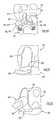
- FIG. 8is a side view of a trial femoral component for use in the methods of the present invention.
- FIG. 9is a top view of the trial femoral component.
- FIG. 10is a sectional view of the trial femoral component taken along line B—B of FIG. 9 .
- FIG. 11Ais a top view of a handle for use with the trial femoral component of the present invention.
- FIG. 11Bis a top view of a modified handle for use with the trial femoral component.
- FIG. 11Cis a side view of the modified handle of FIG. 11B .
- FIG. 11Dis a longitudinal sectional view of the modified handle of FIG. 11B .
- FIG. 12is a perspective view of a femoral resurfacing guide/posterior resection block assembly for use in the methods of the present invention.
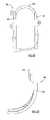
- FIG. 13is a front view of the femoral resurfacing guide.
- FIG. 14is a top view of the femoral resurfacing guide.
- FIG. 15is a side view of the femoral resurfacing guide.
- FIG. 16is a front view of the posterior resection block.
- FIG. 17is a top view of the posterior resection block.
- FIG. 18is a side view of the posterior resection block.
- FIG. 19is a rear view of the posterior resection block.
- FIG. 20is a sectional view of a housing of the posterior resection block taken along line C—C of FIG. 19 .
- FIG. 21is a sectional view of the posterior resection block taken along line D—D of FIG. 17 .
- FIG. 22is a perspective view of a femoral alignment module for use with the posterior resection block and/or tibial crosshead in accordance with the present invention.
- FIG. 23is a top view of an intramedullary or valgus rod for use in the methods of the present invention.
- FIG. 24is a front view of a linking instrument for use with the posterior resection block and valgus rod in the methods of the present invention.
- FIG. 25is a side view of the linking instrument.
- FIG. 26is an opposite side view of the linking instrument.
- FIG. 27is a broken sectional view of a horizontal linking bar of the linking instrument taken along line E—E of FIG. 24 .
- FIG. 28is a perspective view of the femoral resurfacing guide with a femoral resurfacing instrument used in the methods of the present invention.
- FIG. 29Ais a side view of the femoral resurfacing instrument of FIG. 28 .
- FIG. 29Bis a side view of a modified femoral resurfacing instrument for use with the femoral resurfacing guide in the methods of the present invention.
- FIG. 30Ais a top view of the femoral resurfacing instrument of FIG. 28 .
- FIG. 30Bis a top view of the modified femoral resurfacing instrument of FIG. 29B .
- FIG. 31Ais a bottom view of the femoral resurfacing instrument of FIG. 28 .
- FIG. 31Bis a bottom view of the modified femoral resurfacing instrument of FIG. 29B .
- FIG. 32is side view of a femoral fin punch for use with the trial femoral component in the methods of the present invention.
- FIG. 33is an end view of the femoral fin punch.
- FIG. 34is a broken sectional view of the femoral fin punch taken along line F—F of FIG. 33 .
- FIG. 35is a broken perspective view showing the tibial stylus assembled to the tibial crosshead and illustrating the tibial crosshead attached to a tibial alignment guide.
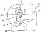
- FIG. 36is a broken perspective view showing the tibial alignment guide positioned on the tibia with a stylus arm of the tibial stylus resting on the lowermost surface of the medial tibial plateau.
- FIG. 37is a broken perspective view of the tibial crosshead fixated to the tibia in the proper position and showing the tibial stylus removed from the tibial crosshead.
- FIG. 38is a broken perspective view showing the trial femoral component located on the femur via the modified handle assembled to the trial femoral component.
- FIG. 39Ais a broken perspective view illustrating the femoral resurfacing guide/posterior resection block assembly positioned on the unprepared femoral condyle.
- FIG. 39Bis a broken anterior view illustrating the femoral resurfacing guide/posterior resection block assembly positioned on the unprepared medial femoral condyle with the femoral alignment module assembled to the posterior resection block.
- FIG. 40is a broken perspective view further depicting the femoral alignment module assembled to the posterior resection block.
- FIG. 41is a broken perspective view showing the valgus rod placed in the femoral intramedullary canal.
- FIG. 42is a broken perspective view illustrating the linking instrument assembled with the femoral resurfacing guide/posterior resection block assembly to form a construct coupled with the valgus rod.
- FIG. 43is a broken perspective view illustrating the properly positioned femoral resurfacing guide/posterior resection block assembly fixated to the femur.
- FIG. 44is a broken perspective view depicting use of the femoral resurfacing instrument to prepare the distal aspect of the femur within a track of the femoral resurfacing guide.
- FIG. 45Ais a broken perspective view depicting assessment of femoral component fit using a template.
- FIG. 45Bis a broken perspective view of the trial femoral component positioned on the prepared femoral condyle and affixed to the femur.
- FIG. 46Ais a broken perspective view showing preparation of the femur for the femoral fixation peg of the femoral component.
- FIG. 46Bis a broken perspective view depicting initial preparation of the femur for the femoral fixation fin of the femoral component.
- FIG. 46Cis a broken perspective view showing use of the femoral fin punch to complete preparation of the femur for the femoral fixation fin.
- FIG. 47is a broken perspective view showing a trial tibial component fixated on the prepared tibial plateau.
- FIG. 48is a broken perspective view depicting a floating trial tibial component positioned on the prepared tibial plateau.
- FIG. 49is a broken perspective view illustrating preparation of the tibia for the posterior tibial fixation peg of the actual tibial component.
- FIG. 50is a broken perspective view depicting preparation of the tibia for the anterior tibial fixation peg of the actual tibial component.
- FIG. 51is a broken perspective view showing pegged trial components placed on the prepared femoral condyle and prepared tibial plateau.
- FIG. 52is a broken perspective view depicting implantation of the actual femoral component and the actual one-piece tibial component on the prepared surfaces of the femoral condyle and tibial plateau, respectively.
- FIG. 53is a front view of an alternative femoral resurfacing guide.
- FIG. 54is a front view of an alternative posterior resection block.
- FIG. 55is a side view of an alternative femoral resurfacing instrument.
- FIG. 56is a side view of another alternative femoral resurfacing instrument.
- FIG. 57is a front view of a further alternative posterior resection block according to the present invention.
- FIG. 58is a side sectional view taken along line G—G of FIG. 57 .
- FIG. 59is a front view of another alternative femoral resurfacing guide.
- FIG. 60is a side view of the femoral resurfacing guide of FIG. 59 .
- FIG. 61is a front view of yet another alternative femoral resurfacing guide.
- FIG. 62is a side view of the femoral resurfacing guide of FIG. 61 .
- FIG. 63is a top view of the femoral resurfacing guide of FIG. 61 .
- FIG. 64is a side view of yet another femoral resurfacing instrument.
- the instruments and methods of the present inventionrelate to implantation of knee joint prostheses and, in particular, to minimally invasive unicompartmental implantation of knee joint prostheses, especially the knee joint prostheses disclosed in the concurrently filed non-provisional patent applications entitled Knee Joint Prostheses, Prosthetic Femoral Components and Prosthetic Tibial Components, the entire disclosures of which were previously incorporated herein by reference.
- the knee joint prostheses and the prosthetic femoral and tibial components discussed hereininclude the knee joint prostheses and the prosthetic femoral and tibial components disclosed in the aforementioned patent applications.
- the instruments and methods of the present inventionmay be used or adapted for use with other knee joint prostheses and may be performed using open surgical techniques.
- the instruments and methods of the present inventionare illustratively described below for medial compartment knee joint replacement of a left or right knee, it should be appreciated that the instruments and methods of the present invention may be used or adapted for use in lateral compartment knee joint replacement of a left or right knee.
- “medial compartment” of a kneerefers to the femoral condyle and corresponding tibial plateau of the knee located closer to the median plane of the patient's body, i.e. the plane that divides the body in half lengthwise
- “lateral compartment” of a kneerefers to the femoral condyle and corresponding tibial plateau of the knee located further from the median plane.
- the term “medial”refers to a side or direction toward the median plane
- the term “lateral”refers to a side or direction away from the median plane
- the term “anterior”refers to a side or direction toward the front of the knee
- the term “posterior”refers to a side or direction toward the back of the knee
- the term “distal”refers to a downward side or direction
- the term “proximal”refers to an upward side or direction.
- FIGS. 1–5A tibial crosshead or cutting guide 10 for use in the methods of the present invention is illustrated in FIGS. 1–5 .
- the tibial crosshead 10is shown as a “left” tibial crosshead for use in implantation of a knee joint prosthesis on the left knee of a patient, and a “right” tibial crosshead in accordance with the present invention for use on a right knee is a mirror image of the “left” tibial crosshead 10 .
- the tibial crosshead 10has an anterior portion 11 of greater height than a posterior portion 12 thereof, the posterior portion 12 forming a curving wing 13 defined by a curved side wall 14 of the posterior portion, a curved posterior wall 15 of the posterior portion and a transition wall 16 of the posterior portion joining the side wall 14 to the posterior wall 15 .
- the side wall 14has a radius of curvature R 1
- the posterior wall 15has a radius of curvature R 2 .
- the anterior portion 11has an inner side wall 17 and a parallel outer side wall 18 spaced outwardly from inner side wall 17 to define a generally C-shaped outer arm extending from the anterior portion.
- a channel 19extends through the anterior portion 11 from top to bottom and is defined by the C-shaped outer arm and by an opposing, C-shaped inner arm formed by a curved internal surface 20 of the anterior portion.
- the channel 19has a configuration in cross-section to receive a shaft of a tibial alignment guide as explained further below.
- An anterior opening along a planar anterior wall 21 of the anterior portion 11extends from top to bottom between the opposing C-shaped arms and provides an entrance to channel 19 .
- the channel 19has a central longitudinal axis that is angled posteriorly from top to bottom relative to a medial-lateral plane perpendicular to a planar resection slot 24 of the tibial crosshead, so as to provide a posteriorly sloped resection through the resection slot 24 of the crosshead when the tibial crosshead is assembled to the tibial alignment guide as explained further below.
- a plurality of fixation holes 22extend entirely through the anterior portion 11 from the planar anterior wall 21 to a planar posterior wall 23 of the anterior portion.
- the lowermost fixation hole 22 ′as shown in FIG. 4 , has an opening on the anterior wall 21 with a center disposed in a plane P 1 parallel to a plane P 2 containing inner side wall 17 .
- the fixation hole 22 ′has a central longitudinal axis disposed in a plane P 3 forming an angle A 1 with plane P 1 .
- the slot 24extends entirely through the tibial crosshead from anterior to posterior, and has a uniform or constant height or depth between upper and lower planar internal surfaces of the tibial crosshead.
- the slot 24may be limited or bounded by a slot end 25 in side wall 14 adjacent transition wall 16 , by a slot end 26 in anterior wall 21 adjacent the C-shaped inner arm, and by slot ends 27 in posterior wall 15 . It should be appreciated that the slot end 25 and/or the slot end 27 can be eliminated in that the slot 24 may extend to and open on the side of the crosshead as shown by dotted lines in FIGS. 1 and 5 .
- a through hole 28is formed in the tibial crosshead perpendicular to the planar top wall thereof for attachment of a tibial stylus as explained below.
- the holecan be provided at one or more suitable predetermined locations as shown by dotted lines in FIG. 2 , and more than one hole 28 can be provided in the tibial crosshead.
- the posterior wall 15conforms to the anatomic configuration of the anterior tibia when the cutting guide 10 is positioned adjacent thereto as explained below.
- An illustrative but not limiting tibial crossheadhas an overall length between planes P 4 and P 5 and an overall width between planes P 6 and P 7 .
- Plane P 2bisects the channel 19 .
- the planar resection slothas a height or depth between the upper and lower internal surfaces.
- the fixation hole 22 ′has an opening on posterior wall 23 with a center located above a planar bottom surface of the anterior portion 11 .
- Three pairs of fixation holeshave openings on the posterior wall 23 with centers located below the planar top surface of the tibial crosshead.
- the angle of channel 19may be five degrees to provide a five degree posteriorly sloped tibial resection relative to a plane perpendicular to the long axis of the tibia, may be seven degrees to provide a seven degree posteriorly sloped tibial resection or may be any other suitable angle to provide a tibial resection of appropriate angle or slope.
- the tibial crossheadcan be designed to provide a tibial resection of neutral, zero or no slope or angle, i.e. within the plane perpendicular to the long axis of the tibia, in which case the central longitudinal axis of channel 19 is not angled from the vertical and is perpendicular to the resection slot 24 .
- Different crossheads having different angles or no anglesmay be provided.
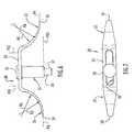
- FIGS. 6 and 7A tibial stylus 30 for use with the tibial cutting guide or crosshead 10 is shown in FIGS. 6 and 7 .
- the tibial stylus 30has first and second curved stylus arms 31 and 32 extending downwardly from opposing ends of a flat connecting plate 33 .
- An elongate, longitudinal slot 34 with radiused endsis formed in connecting plate 33 , and a cylindrical stylus base 35 extends through the slot 34 in a direction perpendicular to plate 33 .
- the slot 34has a length and a width, with the slot 34 being centered between the side edges of connecting plate 33 .
- the stylus base 35may be selectively movable longitudinally within slot 34 and held in place via a cap 36 which may be threaded and/or spring biased to the base 35 .
- a cylindrical stem 37protrudes downwardly from base 35 in axial alignment therewith and mounts a detent 38 , which is illustrated as but not limited to a protruding, spring biased detent ball.
- Stylus arms 31 and 32have respective ends 39 with lower surfaces, respectively, disposed in planes P 8 and P 9 , respectively.
- a lower edge of stylus base 35is contained in a plane P 10 parallel to planes P 8 and P 9 .
- Plane P 10is disposed below planes P 8 and P 9 , and is disposed a greater distance below plane P 9 than plane P 8 .
- the connecting plate 33is of uniform or constant width between opposing, straight side edges thereof, and the stylus arms 31 and 32 taper in width from the connecting plate to their ends 39 , respectively.
- the connecting platehas a thickness and the thickness of the stylus arms tapers from the connecting plate to the ends 39 .
- the detentUpon the detent clearing the upper internal surface of the tibial crosshead, the detent is spring biased to its protruding position to releasably connect the tibial stylus to the crosshead with the lower edge of the stylus base 35 upon the planar top surface of the crosshead.
- the tibial stylus 30is illustrated as a compound tibial stylus capable of establishing a tibial resection through the resection slot of the crosshead at two different depths, i.e. a first depth below the level where the corresponding stylus arm 31 rests on the proximal tibia or a second depth below the level where the corresponding stylus arm 32 rests on the proximal tibia.
- stylus arm 31may be a 4 mm stylus arm for establishing a tibial resection depth 4 mm below the level where the stylus arm 31 rests on the proximal tibia
- the stylus arm 32may be a 2 mm or a 6 mm stylus arm for establishing a tibial resection depth 2 mm or 6 mm below the level where the stylus arm 32 rests on the proximal tibia.
- the stylus arm 31may be a 6 mm stylus arm to establish a 6 mm tibial resection depth below the level where the stylus arm 31 rests on the proximal tibia
- the stylus arm 32may be an 8 mm stylus arm to establish an 8 mm tibial resection depth below the level where the stylus arm 32 rests on the proximal tibia. It should be appreciated, therefore, that the stylus arms can be designed to establish tibial resections of any desired depths.
- the curvatures of the stylus armscorrespond to, conform to, match or follow the anatomic geometry of the femoral condyle such that the stylus arms closely accommodate or cradle the distal surface of the femoral condyle when the stylus arms are positioned on the corresponding tibial plateau as explained further below.
- the design of the stylusenhances ease of use in minimally invasive unicompartmental procedures.
- FIGS. 8–10illustrate a trial femoral component 40 used to properly size and locate the actual or prosthetic femoral component of the knee joint prosthesis.
- Trial femoral component 40is illustrated as a “left” trial femoral component corresponding to the “left” femoral component disclosed in the aforementioned patent application incorporated herein by reference for implantation on the “left” knee of a patient, and a “right” trial femoral component corresponding to a femoral component designed to be implanted on the right knee of a patient is a mirror image of the “left” trial femoral component 40 .
- Trial femoral component 40is similar to the actual femoral component disclosed in the applications incorporated herein by reference and thusly has a femoral trial fixation surface corresponding to the femoral fixation surface of the prosthetic femoral component. Accordingly, the femoral trial fixation surface includes a planar rearward section, a curved intermediate section and a planar forward section corresponding to the rearward, intermediate and forward sections of the femoral fixation surface of the prosthetic femoral component.
- the trial femoral component 40does not have a femoral fixation peg or fin but has a stepped bore hole 41 corresponding to the femoral fixation peg of the actual femoral component and has a slot comprising anterior and posterior slot segments 42 and 43 , respectively, extending from bore hole 41 in correspondence with the anterior and posterior femoral fixation fin segments, respectively, of the actual femoral component. Also, the trial femoral component 40 has stepped, anterior bore holes 44 on opposite sides of anterior slot segment 42 to receive fixation pins or other fixation elements for temporarily fixating the trial femoral component to the femur.
- the counterbored or stepped holes which receive the fixation pinsensure that the heads of the fixation pins are recessed from the outer surface of the trial femoral component corresponding to the femoral articular surface of the actual femoral component.
- the anterior slot segmentterminates anteriorly at an angled end surface 45 that is angled downwardly and anteriorly from the inner surface of the trial femoral component.
- the posterior slot segment 43terminates posteriorly at an angled end surface 46 angled upwardly and posteriorly from the inner surface of the trial femoral component.
- the end surfaces 45 and 46are in a plane P 13 disposed at angle A 2 with a plane P 14 containing a planar anterior section of the inner surface of the trial femoral component.
- the trial femoral component 40may be made available in various sizes corresponding to the sizes of the femoral component disclosed in the application incorporated herein by reference.
- angle A 2is 38 degrees.
- the stepped bore 41has an inner bore section 48 opening on the inner surface of the trial femoral component and an outer bore section 49 opening on the outer surface of the trial femoral component.
- the inner bore section 48has an oblong configuration in cross-section
- the outer bore section 49has a circular configuration in cross-section flaring to an opening along the outer surface of the trial femoral component.
- a selectively attachable handle 50 for use with the trial femoral componentis shown in FIG. 11A and includes an elongate body 51 with a cross-piece 52 forming a T-formation to facilitate grasping.
- a forward end 53 of the body 51defines a trial femoral component holder and a proximal end 54 thereof defines a trial femoral component extractor.
- the forward end 53forms a lip member 55 having an annular groove receiving an O-ring 56 , shown in cross-section.
- the forward end 53is adapted to releasably engage with the stepped bore hole 41 of the trial femoral component 40 .
- a cross pin 57 in the forward end 53protrudes diametrically and prevents rotation of the trial femoral component on the handle by engaging in the anterior and posterior slot segments 42 and 43 of the trial femoral component.
- a modified and preferred selectively attachable handle for use with the trial femoral componentis illustrated at 50 ′ in FIGS. 11B , 11 C and 11 D.
- the handle 50 ′includes elongate body 51 ′ comprising outer body member 51 a ′ and inner body member 51 b ′ slidably disposed in the outer body member.
- the outer body member 51 a ′has a cross-piece 52 ′ forming a T-formation to facilitate grasping and operation.
- a forward end 53 ′ of the inner body member 51 b ′forms a releasable holder for the trial femoral component.
- a bias memberbiases the outer body member 51 a ′ to an extended position shown in FIGS.
- the bias memberis shown as a coil spring disposed around the inner body member 51 b ′ and confined within the outer body member 51 a ′ between an internal shoulder on the outer body member 51 a ′ and an external shoulder on the inner body member 51 b ′.
- the bias membermay comprise other types of springs or other biasing devices including one or more components.
- a wedge element 58 ′ carried by and movable with the outer body member 51 a ′ alongside the inner body member 51 b ′is extended forwardly and, in the retracted position, the wedge element 58 ′ is retracted so that forward end 53 ′ is extended forwardly from or beyond the wedge element 58 ′.
- the outer body member 51 a ′is moved to the retracted position with the forward end 53 ′ disposed forwardly of the wedge element 58 ′ to permit the forward end 53 ′ to be inserted in the bore hole 41 of the trial femoral component.
- the outer body member 51 a ′is returned to the extended position, causing wedge element 58 ′ to be moved into the bore hole 41 alongside the forward end 53 ′ and thereby secure the trial femoral component to the forward end 53 ′ with a wedging action or force.
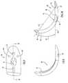
- FIG. 12illustrates a femoral resurfacing guide/posterior resection block assembly including a femoral resurfacing guide 60 and a posterior resection block 70 .
- the femoral resurfacing guide 60is illustrated in FIGS. 12–15 and includes a generally U-shaped rail member having parallel legs 61 and 62 , which curve in the posterior direction to posterior ends connected by a transverse connecting pad 63 , which may be formed integrally, unitarily with the legs.
- the rail memberhas an inside surface 64 defining a track for a femoral resurfacing instrument as described below, the inside surface or track 64 externally delineating an area of the femoral condyle to be resurfaced. As best shown in FIG.
- the connecting pad 63is angled downwardly from leg 61 to leg 62 , and its lower surface is in a plane P 15 that forms an angle A 3 with a horizontal plane P 16 .
- the angle A 3corresponds to the angular sweep of the actual femoral component disclosed in the application previously incorporated herein by reference.
- the connecting padmay be oriented in the horizontal plane between legs 61 and 62 .
- the plane P 16is parallel to a plane P 17 containing a top of the rail member which forms an arcuate, posteriorly protruding stylus or tab 59 for a purpose to be described below.
- the top surface of the connecting pad 63has a recessed surface 65 , and a notch 66 is formed along the inside surface of leg 61 .
- the legs 61 and 62have through holes 67 , respectively, extending therethrough from the front surface to the back surface of the rail member, and the centers of the through holes are in a plane P 18 parallel to plane P 15 .
- An eyelet 68is disposed on leg 61
- eyelets and 69 ′are disposed on leg 62 .
- the legs 61 and 62have posterior radii of curvatures R 7 and R 8 and anterior radii of curvatures R 9 and R 10 as shown in FIG. 15 .
- the femoral resurfacing guide 60is designed for use with a “left” femoral component as disclosed in the application incorporated herein by reference and is thusly a “left” femoral resurfacing guide. It should be appreciated, however, that a “right” femoral resurfacing guide may be provided as a mirror image of the “left” femoral resurfacing guide for use with a “right” femoral component. Also, the femoral resurfacing guide is made available in sizes corresponding to the sizes of the actual femoral components. For example, the illustrated femoral resurfacing guide 60 may be a Size 2 femoral resurfacing guide corresponding to a Size 2 femoral component of the aforementioned patent application.
- the inside surface or track of the femoral resurfacing guide 60follows a configuration corresponding to the anterior-posterior and outer medial-lateral geometry of the actual femoral component and, depending on the actual femoral component, the track of the femoral resurfacing guide may or may not have an angular sweep.
- An illustrative but not limiting femoral resurfacing guidehas an overall height between planes P 16 and P 17 .
- the medial-lateral width of the trackcorresponds to the perpendicular distance between the inside surface of leg 61 and the inside surface of leg 62 .
- the hole for eyelet 68has a center located in a plane parallel to plane P 17 .
- the hole for eyelet 69has a center located in a plane parallel to plane P 17 .
- the center of the hole for eyelet 69 ′is located in a plane disposed at an angle to a sagittal plane bisecting the femoral resurfacing guide 60 vertically.
- the actual dimensions of the femoral resurfacing guidewill depend on the particular size of the femoral resurfacing guide.
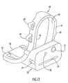
- the posterior resection block 70includes a housing having an anterior or forward portion and a base plate extending posteriorly or rearwardly from the anterior portion.
- the anterior portion for resection block 70has a front surface 71 , a top surface 72 and a back surface 73 curving downwardly from top surface 72 to the elongate, rearwardly extending base plate 74 terminating at a cantilevered planar tongue 75 .
- the base plate 74defines a bottom surface or wall of the housing as shown in FIGS. 16 , 18 and 19 .
- a pair of attachment posts 76extend rearwardly from back surface 73 and are adapted to be received in the through holes 67 of the femoral resurfacing guide with the tongue 75 resting on the recessed surface 65 of the femoral resurfacing guide as shown in FIG. 12 .
- the posterior resection blockis thusly connectible with the femoral resurfacing guide 60 such that the resulting femoral resurfacing guide/posterior resection block assembly may be handled essentially as a one-piece unit or construct for ease of use and simplification of procedural steps.
- the femoral resurfacing guide/posterior resection block assemblymay be provided with or without structure for mechanically locking the posterior resection block to the femoral resurfacing guide.
- a threaded hole 77 and a fixation hole 78open on the front surface 71 and extend rearwardly through the anterior portion of the housing to open on back surface 73 .
- the attachment posts 76 and the holes 77 and 78are aligned with one another in the medial-lateral direction as best shown in FIG. 19 .
- a channel 79extends through the housing in the medial-lateral direction and opens on opposing side walls of the housing.
- the channel 79has a central longitudinal axis transverse or perpendicular to a central longitudinal axis of the housing.
- the channel 79is rectangular in cross-section with its cross-sectional length oriented perpendicular to front surface 71 , which is planar, and its cross-sectional width oriented parallel to front surface 71 .
- threaded hole 77extends perpendicular to front surface 71 and parallel to attachment posts 76 , but could extend at any suitable angle to the front surface.
- Fixation hole 78extends from the front surface 71 at an angle toward threaded hole 77 .
- a central longitudinal axis of fixation hole 78is disposed at angle A 4 with a side wall 80 of the housing.
- a resection slot 81extends through the housing from front to rear, the slot having a front slot opening on front surface 71 and a back slot opening on back surface 73 , which is planar and parallel to front surface 71 .
- the slot 81is planar with a uniform height in the vertical direction between parallel upper and lower internal surfaces of the housing, and the slot 81 is parallel to a bottom surface of base plate 74 and to tongue 75 . It should be appreciated that the posterior resection block and the femoral resurfacing guide need not be assembled and used as an essentially one-piece assembly, but can constitute and be used individually as separate and distinct instruments in multiple procedural steps.
- the posterior resection blockis made available in size ranges, for example, Size 1–2 and Size 3–4, corresponding to the sizes of the prosthetic femoral components of the referenced application.
- the illustrated posterior resection block 70may, for example, be a Size 1–2 posterior resection block for use in implantation of a Size 2 femoral component.
- the posterior resection block 70has an overall length from front to rear, with the base plate 74 extending rearwardly of the back surface 73 ; the front surface 71 has an overall medial-lateral width, with the base plate 74 having a width less than the width of the front surface; the posterior resection block 70 has an overall height in the vertical direction, with the base plate 74 having a height or thickness in the vertical direction less than the overall height and the tongue 75 having a thickness less than the thickness of the base plate; the attachment posts 76 terminate rearwardly of front surface 71 ; the attachment posts 76 have centers spaced from one another, and each attachment post may be spaced the same distance from the sagittal plane defined by line D—D; the centers for the attachment posts 76 are above the planar top surface of the base plate; the resection slot 81 has radiused medial-lateral ends and has a medial-lateral width between the radiused ends; and the slot 81 is centered within the medial-lateral width of the re
- a femoral alignment module 82 for use with the tibial cutting guide or crosshead 10 and/or the posterior resection block 70is illustrated in FIG. 22 and includes an angled tab having a planar leg 83 and a planar foot 84 extending perpendicularly from a first end of leg 83 .
- the same femoral alignment module 82may be used as either a “left” femoral alignment module on the left knee of a patient, or as a “right” femoral alignment module on the right knee of a patient merely by reversing the orientation of the femoral alignment module 82 .
- a second end of leg 83carries a cylindrical barrel 85 having a lumen of circular cross-section extending therethrough.
- the cylindrical barrelprotrudes beyond parallel upper and lower surfaces of leg 83 , and the lumen is perpendicular to the upper and lower surfaces of leg 83 such that the lumen is perpendicular to the plane of foot 84 .
- the leg 83has a height or thickness between its parallel upper and lower surfaces.
- Foot 84extends posteriorly from the leg 83 to a straight posterior edge 87 and is of uniform medial-lateral width between parallel side edges of foot 84 .
- Foot 84has a height or thickness between parallel upper and lower surfaces thereof and is dimensioned to be received in the resection slot 24 of the tibial crosshead 10 and/or the resection slot 81 of the posterior resection block 70 with a close fit.
- the parallel upper and lower surfaces of foot 84are parallel to the upper and lower surfaces of leg 83 , with the foot 84 having a height or thickness slightly less than the height or thickness of leg 83 .
- the first end of leg 83is joined to the foot 84 by a curved outside corner, and the second end of leg 83 is curved or rounded.
- An extramedullary check rod 88is insertable in the lumen of barrel 85 to protrude upwardly and downwardly from the barrel.
- the check rod 88may be slidably and rotatably mounted or received in the lumen of the barrel and may be held in a desired position via a friction or interference fit with the barrel.
- the check rodmay be provided with indicia to facilitate proper directional orientation.
- FIG. 23An intramedullary rod or valgus rod 90 for use in the methods of the present invention is illustrated in FIG. 23 and includes a longitudinal bone insertion element 91 and a handle 92 extending from a rearward end of bone insertion element 91 at an angle A 5 .
- Bone insertion element 91has longitudinal flutes in its external surface and has longitudinally extending vanes 93 protruding radially outwardly from its external surface. The flutes allow the rod 90 to be inserted into the femoral intramedullary canal without pressurizing the marrow.
- Vanes 93only one of which is visible in FIG. 23 , are located at diametric locations on bone insertion element 91 and are thusly spaced about 180 degrees from one another.
- the vanes 93prevent rotation of the valgus rod 90 in the intramedullary canal during use thereof and have sharpened, angled edges 94 that point outwardly to facilitate extraction or removal of the valgus rod from the intramedullary canal after use thereof.
- the hand 92has diametrically opposed flat surfaces, as best seen in FIG. 42 , for a purpose described below in greater detail.
- the angle A 5is defined between plane P 20 containing the central longitudinal axis of bone insertion element 91 and a plane P 21 containing the central longitudinal axis of the handle 92 . Angle A 5 approximates the valgus angle of the distal femur, and valgus rods having different angles A 5 can be provided.
- valgus rodscan be provided having angles A 5 of 3 degrees, 5 degrees and 7 degrees, respectively.
- a single valgus rodcan be used for both left and right knees merely by reversing its orientation.
- a top surface of the valgus rodcan be provided with indicia, such as the word “left”, indicating orientation for use on the left knee
- a bottom surface of the valgus rodcan be provided with different indicia, such as the word “right”, indicating orientation for use on the right knee.
- the valgus rodWhen the “left” indicating indicia faces upwardly, the valgus rod will be oriented for use on the left knee, and when the “right” indicating indicia faces upwardly, the valgus rod will be oriented for use on the right knee.
- Linking instrument 100for use with posterior resection block 70 and valgus rod 90 is illustrated in FIGS. 24–27 .
- Linking instrument 100includes a vertical linking bar 101 and a horizontal linking bar 102 perpendicular to vertical linking bar 101 .
- the horizontal linking bar 102has an end joined to an L-shaped socket 103 .
- socket 103extends anteriorly from the horizontal linking bar 102 and has a channel 104 extending therethrough from top to bottom.
- a detentis associated with the channel 104 and may comprise a ball plunger 105 mounted in and partially occupying the cross-sectional dimension of the channel 104 .
- a portion of the channel cross-sectional dimension not occupied by plunger 105is of a size and configuration to receive the vertical linking bar 101 therethrough, the vertical linking bar being shown removed from the channel 104 in FIG. 27 .
- the vertical linking bar 101is slidably disposed in channel 104 and is confined in a desired position in the channel by the detent, such as the plunger 105 and a locking screw 106 engaged with a longitudinal groove 107 formed in a side wall of the vertical linking bar.
- An upper end of the vertical linking bar 101carries a fixture 108 having a passage 109 extending therethrough from anterior to posterior, with a central longitudinal axis of passage 109 being perpendicular to the central longitudinal axis of the vertical linking bar and also being perpendicular to a central longitudinal axis of horizontal linking bar 102 .
- the passage 109has a cross-sectional size and configuration to receive the handle 92 of valgus rod 90 with a close fit.
- the horizontal linking bar 102has a size and configuration in cross-section to be received in the channel 79 of the posterior resection block 70 with a close fit.
- the linking instrumentmay be made available in different sizes.
- FIG. 28illustrates a femoral resurfacing or tissue removing instrument 110 for use with the femoral resurfacing guide 60 to resurface a femoral condyle to accommodate the femoral component of the knee joint prosthesis.
- the femoral resurfacing instrument 110is illustrated as but is not limited to a femoral rasp, which may be provided in sizes corresponding to the sizes of the femoral resurfacing guide.
- a Size 2 femoral raspmay be provided for use with a Size 2 femoral resurfacing guide.
- the femoral raspcan be made available in other sizes corresponding to other sizes of the femoral resurfacing guide. It should be appreciated, however, that the resurfacing instrument may be size independent.
- the femoral resurfacing instrument or rasp 110includes a cutting member, a tissue removing member, or an abrading member 111 connected to an angled flange or shaft 113 by which the tissue removing member is coupled with a handpiece, which may be a manual handpiece or a powered handpiece.
- a rearward end of the flange 113is shown connected to an adapter 112 designed for connection to a standard powered handpiece or instrument by which the tissue removing member 111 is reciprocated.
- tissue removing membermay be connected to or formed with various handpieces by which the tissue removing member may be manually moved to effect resurfacing, and such handpieces may be integral and unitary with the tissue removing member or separate therefrom.
- the angled flange 113has a 90 degree bend with a rearward portion of the flange extending upwardly from the bend and a forward portion of the flange extending forwardly from the bend at a right angle to the rearward portion as shown in FIG. 29A .
- the tissue removing member 111has a bottom wall 116 with a straight rear edge 114 joined to opposite ends of an upstanding curved side wall 115 .
- the side wall 115may follow a configuration substantially corresponding to the anterior configuration of the femoral component and forms an abutment for engaging the inside surface 64 of the rail member of the femoral resurfacing guide 60 .
- the bottom wall 116 of the tissue removing memberis circumscribed by rear edge 114 and side wall 115 , and a lower surface of bottom wall 116 is covered in a pattern of cutting teeth 117 to define a cutting, tissue removing or abrading surface that fits within the track of the rail member of the femoral resurfacing guide 60 .
- the tissue removing surfaceis illustrated as being planar but may be non-planar and may be curved.
- the cutting teeth 117provide a bidirectional or multidirectional cutting action in that the cutting teeth 117 are configured to remove tissue as the tissue removing member is moved in more than one direction along the delineated area, for example, anteriorly and posteriorly along the delineated area. Accordingly, tissue removal is accomplished in response to both forward/anterior and rearward/posterior movements of the tissue removing member along the area delineated by the rail member.
- a ledge 118protrudes from the top of side wall 115 and the distance between the ledge 118 and the tissue removing surface limits or controls the depth of resurfacing via engagement of a lower surface of the ledge with an abutment wall carried by the rail member of the femoral resurfacing guide 60 .
- the tissue removing surfaceprotrudes a predetermined distance from the back or posterior surface of the rail member when an engagement wall formed by the lower surface of the ledge engages an abutment wall formed by the front surface of the rail member, such that the ledge defines a stop limiting the depth of resurfacing as described further below.
- bottom wall 116is recessed below the ledge 118 , and a plurality of apertures 119 may be formed through bottom wall 116 to allow passage of bone fragments or other anatomical tissue debris away from the tissue removing surface.
- the resurfacing instrumentthusly controls the depth to which tissue is removed and effects an improved bone surface for implantation compared to current conventional techniques.
- a modified and preferred femoral rasp for use as the femoral resurfacing instrument in the methods of the present inventionis illustrated at 110 ′ in FIGS. 29B , 30 B and 31 B.
- the femoral rasp 110 ′is similar to femoral rasp 110 but does not have apertures in bottom wall 116 ′.
- the bottom wall 116 ′could be provided with apertures as described for bottom wall 116 of femoral rasp 110 .
- the cutting teeth 117 ′ for rasp 110 ′differ from the cutting teeth 117 for rasp 110 in that the cutting teeth 117 ′ are deeper and larger and provide a monodirectional or unidirectional cutting action.
- the cutting teeth 117 ′are configured to remove anatomical tissue as the tissue removing member is moved in one direction, for example rearwardly or posteriorly, along the delineated area.
- the cutting teeth 117 ′can be configured to effect unidirectional cutting as the tissue removing member is moved anteriorly or forwardly along the delineated area.
- the connection used in femoral rasp 110 ′ to connect the flange 113 ′ with the adapter 112 ′is different than the connection used in femoral rasp 110 .
- a femoral fin punch 120is shown in FIGS. 32–34 for use with trial femoral component 40 to prepare the femur for the femoral fixation fin of the actual femoral component.
- the femoral fin punch 120has a rearward end or handle 121 and a forward end or punch member 122 mounted to or formed as part of the handle 121 .
- the punch member 122has a peg element 123 axially aligned with handle 121 and a fin element comprising an anterior fin element 124 extending anteriorly from peg element 123 and a posterior fin element 125 extending posteriorly from peg element 123 .
- the anterior and posterior fin elementshave inner edges 126 , respectively, that are pointed to penetrate bone.
- the peg element 123has a configuration corresponding to the femoral fixation peg of the actual femoral component, and the anterior and posterior fin elements 124 and 125 have configurations corresponding to the anterior and posterior femoral fixation fin segments of the actual femoral component.
- the anterior and posterior fin elements 124 and 125are dimensioned to fit within the anterior and posterior slot segments 42 and 43 , respectively, of the trial femoral component 40 with a close fit.
- the peg element 123is configured to fit in the bore hole 41 of the trial femoral component 40 with a close fit.
- the peg elementWhen fully inserted in the bore hole and slot segments of the trial femoral component during a knee replacement procedure, the peg element seats in a previously drilled hole in the femur and the anterior and posterior fin elements punch depressions in the bone of the proper configuration, size and depth to receive the corresponding anterior and posterior femoral fixation fin segments of the actual femoral component as described further below.
- the peg element 123In the femoral punch 120 , the peg element 123 is mounted or disposed in a recess 128 between the anterior and posterior fin elements, and the peg element protrudes from a bottom surface 129 of the recess contained in a plane P 23 .
- anterior edge surface 29 of anterior fin element 124 and a posterior edge surface 29 ′ of posterior fin element 125are contained in plane P 22 forming angle A 6 with plane P 23 .
- the anterior edge surface 29abuts the end surface 45 of the anterior slot segment and the posterior edge surface 29 ′ abuts the end surface 46 of the posterior slot segment to form a depth stop limiting penetration of the punch member into the femur.
- angle A 6is 38 degrees.
- the instruments and methods of the present inventionare most preferably used with the unicompartmental knee joint prostheses disclosed in the referenced application, which closely replicate the geometry and kinematics of the medial compartment of the knee, but may be used or adapted for use with other knee joint prostheses.
- Use of the instruments and methods of the present invention as described belowis applicable to medial or lateral compartment knee joint replacement in cases of unicompartmental disease without contraindications, and the disclosure of a medial compartment procedure should be construed as illustrative and not limiting.
- Projected femoral and tibial component sizes and alignment goalsare determined prior to surgery through radiographic analysis including standard weight-bearing anterior-posterior and lateral films, which are also used to diagnose medial compartment disease.
- a diagnostic arthroscopymay be performed to confirm the absence of contraindications including tricompartmental disease, inflammatory arthritic disorders such as rheumatoid arthritis, ACL insufficiency and crystal-induced arthr
- the medial, lateral, superior and inferior borders of the patellaare marked with the knee in flexion.
- the tibial tubercle and joint lineare palpated.
- Surgeryis initiated by accessing the medial compartment of the knee through a 3–5 inch medial perapatellar incision beginning at the medial border of the patella and carried distally to the level of the tibial tubercle, with the incision paralleling the medial border of the patellar tendon to expose the medial compartment of the knee.
- the proximal portion of the retinacular incisionis extended proximally and medially in a “hockey stick” fashion just below the distal fibers of the vastus medialis.
- the incisioncan be extended proximally and/or distally as needed. If present, the medial patellar osteophyte should be removed. The medial border of the patella can be removed, as needed, to facilitate exposure. In performing the medial meniscectomy, it may be helpful to excise the anterior horn of the meniscus and complete the meniscectomy following the proximal tibial resection.
- the thusly exposed knee 140which is shown as a left knee but which may be a right knee, is flexed to 90 degrees and the appropriate “left” or “right” tibial cutting guide or crosshead is attached to a tibial alignment guide.
- FIGS. 35 and 36shown the tibial cutting guide 10 attached to a tibial alignment guide 130 including an extendable and retractable shaft assembly 131 having a lower end mounted to an adjustable ankle clamp 132 . Selected extension and retraction of the shaft assembly 131 vertically is permitted via adjusting screw 133 .
- the extendable shaft assembly 131includes an extendable upper shaft 135 having a wider upper grooved portion 136 a connected with a narrower lower rod portion 136 b upon which an adjusting sleeve 1234 is disposed.
- the lower portion 136 bis externally threaded, and the adjusting sleeve 134 is internally threaded to permit the adjusting sleeve to be rotated relative to the upper shaft to effect movement of the adjusting sleeve vertically upwardly and downwardly along the upper shaft.
- the tibial alignment guidemay be a standard extramedullary tibial alignment guide of the type sold by Wright Medical Technology as Part Nos. K0063001 and K0040103. FIGS.
- 35 and 36show the tibial cutting guide 10 assembled to the tibial alignment guide 130 by lowering the adjusting sleeve 134 to permit insertion of the lower portion 136 b of upper shaft 135 through the anterior opening of channel 19 and by thereafter raising the adjusting sleeve so that the grooved portion 136 is positioned snugly in the channel 19 of the tibial cutting guide with the tibial cutting guide resting at the mid-point of the proximal tibial alignment guide.
- the tibial alignment guide 130with the tibial cutting guide 10 assembled thereto, is placed onto the tibia 138 by applying the ankle clamp 132 , with the ankle clamp positioned at or slightly medial to the mid-point of the medial and lateral malleoli as shown in FIG. 36 .
- the shaft assembly 131is placed parallel to or along the long axis of the tibia, particularly the tibial shaft, and is positioned proximally at the medial third of the tibial tubercle or another appropriate landmark for correct tibial rotation.
- tibial resectionsuch as a five degree posteriorly sloped tibial resection
- tibial cutting guide 10a downward posteriorly sloped tibial resection, such as a five degree posteriorly sloped tibial resection, through the resection slot 24 of the tibial cutting guide 10 relative to the plane perpendicular to the long axis.
- Moving the shaft assembly away from the ankleincreases posterior slope while moving the shaft assembly toward the ankle joint reduces the posterior slope.
- Different tibial cutting guides or crossheads providing different resection anglesmay be provided so that the posterior slope can be varied by using a different tibial cutting guide.
- a tibial cutting guidecan be provided to obtain a tibial resection of neutral, zero or no slope or angle relative to the plane perpendicular to the long axis. It is desirable to match the anatomic slope as closely as possible while avoiding excessive posterior angulation.
- the posterior wall of the tibial cutting guideis positioned adjacent the anterior tibia and conforms to and accommodates the anatomic configuration or geometry of the anterior tibia to facilitate the minimal incision technique.
- the tibial stylus 30is assembled onto the tibial cutting guide 10 by inserting the stem 37 of the tibial stylus through an appropriate through hole 28 of the tibial cutting guide until the tibial stylus is locked in place via the detent ball 38 as shown in FIGS. 35 and 36 .
- the shaft assembly 131is adjusted to adjust the height of the tibial cutting guide 10 so that the selected stylus arm is located to rest on the tibial plateau 139 .
- FIGS. 35 and 36illustrate the lower surface of end 39 of the stylus arm 32 , i.e. a 6 mm stylus arm, resting on the tibial plateau for a tibial resection 6 mm below the level where the stylus arm 32 rests on the tibial plateau.
- the lower surface of the stylus armmay be placed on the lowest surface of the tibial plateau.
- the knee 140is maintained in flexion, with the tibia 138 rotated 90 degrees relative to the femur 142 as shown in the drawings.
- the anatomic curvature of stylus arm 32accommodates the anatomic geometry of the distal surface of the femoral condyle with the end of the stylus arm positioned between the femoral condyle and tibial plateau with the knee in flexion and also with the knee in extension.
- Proper tibial rotationis maintained, and the tibial cutting guide 10 is fixated to the tibia 138 via fixation pins or other fixation elements 143 inserted through the middle pair of fixation holes 22 of the tibial cutting guide 10 as shown in FIG. 37 .
- the femoral alignment module 82may be used to evaluate and confirm proper positioning of the resection slot 24 by inserting the foot 84 of the femoral alignment module in the resection slot 24 as described below for the resection slot of the posterior resection block 70 and as shown in FIGS. 39B and 40 for the posterior resection block.
- the proximal tibial resectionmay be performed with or without the tibial alignment guide 130 in place, in that the tibial alignment guide may be removed from the tibial cutting guide once the tibial cutting guide has been fixated to the bone and prior to the proximal tibial resection being performed.
- the adjusting sleeve 134is turned so that the narrower rod portion 136 b of upper shaft 135 may be withdrawn through the anterior opening of the channel 19 .
- the depth of the tibial cutting guide 10may be further adjusted by removing the tibial cutting guide from the middle pair of fixation pins 143 and moving the tibial cutting guide over the fixation pins so that the fixation pins are inserted and received in the upper pair of fixation holes 22 at a plus 2 mm position or are inserted and received in the lower pair of fixation holes 22 at a minus 2 mm position.
- the tibial cutting guidecan be adjusted upwardly and downwardly to individualize for the particular patient the amount of bone removed from the tibia for the proximal tibial resection.
- a divergent headless fixation pin or other fixation elementmay be applied via the fixation hole 22 ′.
- a proximal resection of the tibiais initiated using a cutting member C through the resection slot 24 as depicted in FIG. 37 .
- a one half inch wide (0.050 inch/1.3 mm thick) oscillating planar saw blade driven by a powered handpiece or instrumentis used as the cutting member inserted through resection slot 24 .
- the cutting membermay be introduced or inserted in the slot 24 from the anterior and/or the medial side of the tibial cutting guide.
- a planar resected surface 144is thusly formed in the proximal tibia as shown in FIG.
- the proximal tibial resectionis completed by forming a sagittal resected surface 145 , typically using a reciprocating saw blade, aligned with the lateral border of the medial femoral condyle while taking care to avoid the anterior and posterior cruciate ligaments, the sagittal resected surface being shown in FIG. 38 .
- the sagittal resected surface 145can be made first using the reciprocating saw blade, which can be left in place on the proximal tibia to act as a landmark for making the planar resected surface 144 in the proximal tibia as discussed above. If necessary, the posterior horn of the medial meniscus may be removed prior to preparing the femur.
- preliminary sizing for the actual femoral component to be implantedis determined by utilizing a trial femoral component.
- a linemay be etched or marked on the femoral condyle to indicate the weight bearing axis, which may be determined by observing the line of visible wear along the femoral condyle.
- a selected size trial femoral componentis attached to the trial component handle as described above.
- FIG. 38shows trial femoral component 40 attached to handle 50 ′, with the handle 50 ′ grasped by the surgeon to locate the trial femoral component 40 on the femur 142 .
- the trial femoral component 40is positioned on the unprepared femoral condyle, as shown for the medial femoral condyle, to estimate correct sizing based on medial-lateral component width and overall anterior-posterior sizing. Because a posterior femoral resection has not yet been performed, the anterior/superior location of the trial femoral component will not represent the final location of the actual femoral component. Following the posterior femoral resection, the femoral component will be positioned approximately 7 mm anterior/superior to its position during trialing.
- the anterior portion of the actual femoral componentshould be positioned on the femoral condyle at the tidemark between the degenerative weight-bearing surface and the healthier articular cartilage.
- the femurmay be marked with methylene blue to indicate the central weight-bearing line and medial-lateral aspects of the trial femoral component.
- Final component sizingis determined with the femoral resurfacing guide 60 and posterior resection block 70 .
- the appropriate size “left” femoral resurfacing guide for left knee implantation or the appropriate size “right” femoral resurfacing guide for right knee implantationmay be attached to the appropriately sized posterior resection block 70 to form a one-piece assembly or construct by inserting the attachment posts 76 of the posterior resection block 70 in the through holes 67 of the femoral resurfacing guide 60 .
- FIG. 39Adepicts the “left” femoral resurfacing guide 60 attached to the posterior resection block 70 .
- a threaded handle 146can be inserted into the threaded hole 77 of the posterior resection block 70 to extend parallel to the planar resection slot 81 and perpendicular to the anterior or front wall of the resection block.
- the handle 146assists in manipulating the femoral resurfacing guide 60 /posterior resection block 70 assembly for placement on the femur and may be used to evaluate the flexion/extension position and the varus/valgus position of the femoral instrumentation.
- the femoral resurfacing guide 60 and posterior resection block 70need not be assembled prior to being placed on the femur but can be placed on the femur in separate procedural steps. Accordingly, the following procedural description in which the femoral resurfacing guide 60 and posterior resection block 70 are assembled prior to being positioned and aligned on the femur should be considered illustrative and not limiting.
- the femoral resurfacing guide 60 /posterior resection block 70 assemblyis positioned on the femur with the knee in flexion and the base plate 74 of the resection block disposed between the posterior aspect of the femoral condyle and the resected surface 144 as shown in FIG. 39A .
- the stylus 59 of the femoral resurfacing guidecontacts the bone for proper positioning of the femoral resurfacing guide and to control the depth of resurfacing.
- the stylus 59prevents the femoral resurfacing guide from rolling over into hyperextension and provides an indication of where the prosthetic femoral component will transition into the bone.
- the position and size of the stylus 59prevents mal-positioning of the femoral resurfacing guide while maintaining the proper depth of resurfacing.
- the bottom surface of base plate 74 of the posterior resection block 70will rest on the previously formed resected surface 144 of the proximal tibia to ensure that a planar posterior resection of the femur established via resection slot 81 is parallel to the tibial resection 144 for proper balancing of the implanted knee joint.
- spacers or shimscan be introduced between the base plate and the bone to maintain the parallel relationship between the tibial resection and the posterior portion of the femoral resurfacing guide/posterior resection block assembly. If the posterior portion of the femoral resurfacing guide/posterior resection block assembly is maintained parallel to the tibial resection, the posterior resection of the femur will be parallel to the tibial resection. This linking of the femoral resection to the tibial resection helps the surgeon balance the joint space and determine proper positioning of the instruments and prosthesis.
- Proper alignment and positioningmay be established and confirmed using an extramedullary technique and/or an intramedullary technique.
- the femoral resurfacing guide 60 /posterior resection block 70 assemblyis positioned and aligned on the unprepared femoral condyle using one or more of the following extramedullary steps or techniques and, preferably, all or a combination of the following extramedullary steps or techniques.
- the knee 140is flexed to 90 degrees and the handle 146 is positioned parallel to the femur and perpendicular to the tibia when viewed from the lateral or medial side as shown by dotted lines in FIG. 39A .
- the handle 146is used to evaluate flexion/extension and varus/valgus positioning.
- the planar resected surface 144 of the proximal tibiamay also be used to confirm correct positioning of the posterior resection block 70 in that the bottom surface of the base plate 74 rests on the resected surface 144 with resection slot 81 parallel to resected surface 144 .
- the femoral resurfacing guide 60 /posterior resection block 70 assemblyis positioned in the correct medial-lateral and rotational position along the distal weight bearing surface of the femoral condyle to obtain maximum femoral coverage as shown in FIG. 39B .
- the inside surface 64 or track of the rail membercorresponds to the outer medial-lateral geometry of the femoral component and thusly provides an indication of maximum femoral coverage, with the stylus 59 indicating where the femoral component will transition into the bone.
- a third step or technique for positioning and aligning the femoral resurfacing guide 60 /posterior resection block 70 assemblyinvolves ensuring that the femoral resurfacing guide/posterior resection block assembly is rotated correctly for femoral alignment as also shown in FIG. 39B .
- the prosthetic femoral component disclosed in the application incorporated herein by referenceprovides an anatomic angle, such as 7 degrees, between the distal and posterior portions, which should closely replicate the anatomic geometry of the femoral condyle.
- Final rotational positioningmay be confirmed via the inside surface 64 of the femoral resurfacing guide 60 and by utilizing the femoral alignment module 82 as depicted in FIGS. 39B and 40 .
- the foot 84 of the femoral alignment module 82is inserted in the resection slot 81 of posterior resection block housing.
- the foot 84protrudes posteriorly from the back surface of the housing for resection block 70 , thereby establishing a location for a posterior resection of the femur through the slot 81 of the resection block.
- a fourth step or techniquealso represented by FIGS.
- the foot 84is inserted in the resection slot 81 and the check rod 88 of the femoral alignment module 82 is used to confirm that the femoral resurfacing guide/posterior resection block is parallel to the long axis of the femur 142 and perpendicular to the long axis of tibia 138 , thereby ensuring proper flexion-extension positioning.
- An alternative or additional alignment techniqueincludes the intramedullary alignment technique represented in FIGS. 41 and 42 and involves initiating or forming an opening 148 in the femoral intramedullary canal 149 , typically using a 3 ⁇ 8 inch (9.5 mm) diameter drill bit or cutting member. Routine irrigation and aspiration should be performed to reduce the possibility of fat emboli.
- the femoral resurfacing guide 60 /posterior resection block 70 assemblyis coupled with the appropriate size linking instrument 100 to form a one-piece assembly or construct by inserting the horizontal linking bar 102 in the channel of the posterior resection block 70 as shown in FIG. 42 .
- the indicia indicating “left”is positioned to face upwardly for unicompartmental surgery on the left knee.
- the valgus rod 90is placed into the intramedullary canal via the opening 148 without seating the vanes 93 of the valgus rod into the bone as shown in FIGS. 41 and 42 .
- the one-piece assembly or construct formed by the femoral resurfacing guide/posterior resection block assembly and the linking instrumentis coupled with the valgus rod 90 by placing the handle 92 of valgus rod 90 through the passage 109 of fixture 108 .
- the flat surfaces on the handle 92mate with the flat walls of passage 109 .
- the femoral resurfacing guide/posterior resection block assemblyis then positioned and aligned utilizing the extramedullary alignment steps or techniques discussed above. Femoral alignment is finalized by impacting the end of handle of the valgus rod 90 and fully seating the vanes 93 in the intramedullary canal.
- the seated vanes 93prevent the valgus rod from rotating.
- the femoral resurfacing guide 60 /posterior resection block 70 assemblyis correctly positioned with base plate 74 flush against the tibial resected surface 144 and against the posterior femoral condyle, with or without the use of shims or spacers for the base plate.
- the femoral resurfacing guide 60is pinned in place via fixation pins or other fixation elements 150 inserted in the holes of eyelets 68 , 69 and 69 ′, respectively, as shown in FIG. 43 .
- fixation pins or other fixation elements 150inserted in the holes of eyelets 68 , 69 and 69 ′, respectively, as shown in FIG. 43 .
- 0.125 inch (3.2 mm) headless fixation pins 150are used.
- An additional fixation pin or other fixation element 151is placed in the divergent fixation hole 78 of the posterior resection block 70 to ensure it remains stable during resection of the posterior femoral condyle.
- the eyeletsare located and oriented to cooperate with the fixation pins inserted therein to retract the patella and surrounding soft tissue for enhanced exposure of the knee joint when the femoral resurfacing guide is attached to the femur. Particularly, the patella is retracted and prevented from interfering with surgical preparation of the femur.
- fixation pins in the eyeletsprovide secure fixation of the femoral resurfacing guide to the femur and adequate retraction of the patella and soft tissue, which is critical to good surgical exposure, particularly in a minimally invasive procedure.
- a cutting membersuch as cutting member C, is inserted through the resection slot 81 of the posterior resection block 70 to resect the posterior aspect of the femoral condyle along a plane parallel to the planar surface 144 of the tibia as shown in FIG. 43 .
- a one half inch wide planar sagittal saw blade(0.050 inch/1.3 mm thick) powered by a powered handpiece or instrument is used as the cutting member inserted through the resection slot 81 .
- the planar resection formed through the slot 81will typically remove about 4–7 mm of bone, and more typically 7 mm of bone, from the most prominent point along the posterior aspect of the femoral condyle, resulting in a planar posterior resected surface 153 shown in FIG. 44 .
- the rail member of femoral resurfacing guide 60is angled in a medial-lateral direction from posterior to anterior relative to the plane of the resection slot 81 as may be best shown in FIG. 39B , but does not have to be angled as discussed above depending on the femoral component to be implanted.
- the fixation pin 151is removed, and the posterior resection block 70 and linking instrument 100 are removed, leaving the femoral resurfacing guide 60 in place as shown in FIG. 44 .
- the valgus rod 90may be allowed to remain in the intramedullary canal to retract the patella and soft tissue or may be extracted from the intramedullary canal, with the sharp edges on the vanes of the valgus rod facilitating its extraction.
- the appropriate size femoral resurfacing instrument 110may be attached to a reciprocating powered handpiece or instrument, such as a power saw, via the adapter 112 to effect mechanical reciprocation of the tissue removing member 111 .
- a reciprocating powered handpiece or instrumentsuch as a power saw
- the tissue removing membercan be manipulated manually via a manual handpiece or instrument to effect the necessary cartilage and/or bone removal.
- the tissue removing member 111is placed within the area externally delineated by the inside surface 64 of the rail member, and the tissue removing surface of the tissue removing member is positioned against the most prominent surface of the femoral condyle delineated by the track.
- the handpieceis used to reciprocate the tissue removing member 111 , and the tissue removing surface of the tissue removing member removes cartilage and/or articular bone in preparation for the femoral component.
- the tissue removing memberis moved within the area delineated or outlined by the inside surface 64 of the rail member, with the U-shaped side wall of the tissue removing member serving as an abutment with the inside surface 64 of the femoral resurfacing guide 60 .
- the lower surface of ledge 118 maintained above or atop the anterior surface of the rail member as the tissue removing member is moved along the delineated areaprovides a stop to ensure that the articular surface of the femur is removed to a predetermined depth.
- FIG. 44shows the femoral resurfacing instrument 110 directed along the delineated area in an upward direction; however, the femoral resurfacing instrument may be directed in a downward direction. In either case, the femoral resurfacing instrument must be directed in the upward direction to complete resurfacing of the femur at the most superior/anterior portion of the femoral resurfacing guide.
- the appropriate level of preparationis complete when the side wall of the tissue removing member 111 contacts the inside surface 64 of the rail member and when the lower surface of the ledge 118 contacts the front surface of the rail member along its entire path of travel along the delineated area to obtain a smooth, curved, resurfaced area or surface 157 on the distal aspect of the condyle.
- the bone surfacemay be checked and femoral component fit assessed using the trial femoral component 40 and/or an appropriate sized femoral shaping template 159 as shown in FIG. 45A to ensure a proper fit for the actual femoral component prior to removal of the femoral resurfacing guide.
- the template 159has an inner surface with an anterior-posterior dimension corresponding to the anterior-posterior dimension of a prosthetic femoral component and a sagittal contour corresponding to the sagittal contour of the fixation surface of the prosthetic femoral component.
- the template 159has an attached handle and is positionable on the prepared bone surface within the area delineated by the rail member of the femoral resurfacing guide 60 .
- the area 157is externally delineated or bounded medially, laterally and superiorly/anteriorly by the rail member of the femoral resurfacing guide and is bounded inferiorly/posteriorly by the previously prepared planar posterior resected surface 153 .
- the resurfaced area 157 formed using the femoral resurfacing guidemerges smoothly with the resected surface 153 and, during resurfacing, the femoral resurfacing guide properly and controllably guides the tissue removing member to obtain a smooth merger while preventing the tissue removing member from removing bone too far inferiorly/posteriorly.
- a layer of cartilage and/or boneis removed from the distal aspect of the femoral condyle to a controlled depth while essentially retaining the anatomic geometry of the distal aspect of the femoral condyle, as opposed to planar resections or cuts which substantially alter the anatomic geometry.
- the femoral condyle prepared in accordance with the present inventionthusly has the prepared planar posterior resected surface or area 153 and the distal resurfaced area or surface 157 merging with and extending anteriorly from the resected surface 153 .
- the resurfaced areamatches a plurality of tangent radii of the fixation surface of the prosthetic femoral component in the sagittal plane and matches the angular sweep, i.e. 5 to 9 degrees, of the prosthetic femoral component in the coronal plane. Accordingly, the resurfaced area 157 extends anteriorly from the resected surface 153 at an angle in the medial-lateral direction corresponding to the anatomic angle of the femoral condyle. In the case of a medial femoral condyle, the resurfaced area 157 extends anteriorly from the resected surface 153 at a lateral angle.
- the resurfaced areathusly preserves the anatomic sweep of 5–9 degrees for the femoral condyle.
- the resected surface 153 and the resurfaced area 157define a prepared surface for receiving the femoral fixation surface of the actual femoral component described in the co-pending patent application incorporated herein by reference, and the prepared surface follows the contour of the femoral fixation surface.
- the femoral resurfacing guide 60is removed, and the appropriate size “left” trial femoral component for left knee implantation or the appropriate size “right” trial femoral component for right knee implantation is positioned on the prepared femoral surface as shown in FIG. 45B for “left” trial femoral component 40 . It may be necessary to clean up the edges of the prepared femoral surface with a rongeur or hand rasp where the femoral resurfacing guide was seated to the bone. This will facilitate medial-lateral adjustment of the trial and prosthetic femoral components.
- the trial femoral component 40is positioned flush against the flat resected surface 153 previously made on the posterior femoral condyle. Particularly, a planar rearward section of the trial femoral component fixation surface corresponding to the planar rearward section of the femoral fixation surface of the prosthetic femoral component is placed flush against the posterior resected surface 153 .
- the trial femoral componentis positioned to maximally cap the femoral condyle and to restore the normal tracking angle of the femoral condyle on the tibia without edge loading and edge contact.
- the handle 50 ′assists in evaluating the flexion/extension positioning and varus/valgus positioning. Correct medial-lateral placement of the trial femoral component is confirmed, and the trial femoral component 40 is pinned in place via fixation pins or other fixation elements 152 inserted in the anterior bore holes 44 of the trial femoral component. The handle 50 ′ is removed or withdrawn from the trial femoral component once the trial femoral component has been fixated to the femur. Prior to pinning the trial femoral component, a trial tibial component may be positioned on the tibia as described below and a trial range of motion may be completed to ensure correct implant tracking.
- Trial range of motionmay be performed subsequent to the trial femoral component being fixated to the femur, since the heads of the fixation elements 152 are recessed in the bore holes 44 and do not protrude beyond or interfere with the outer surface of the trial femoral component.
- the trial tibial componentcan be moved, as needed, to ensure correct implant tracking prior to preparing the femur for the fixation peg and fin of the actual femoral component. Correct implant tracking is confirmed by ensuring that the tracking pattern of the trial femoral and tibial components in flexion and extension follows the normal tibiofemoral tracking pattern.
- Preparation of the femur to accommodate the femoral fixation peg of the actual femoral componentis effected using a femoral peg drill or cutting member 161 of appropriate size inserted in the bore hole 41 of the trial femoral component 40 as shown in FIG. 46A .
- the cutting member 161should be positioned perpendicular to the femoral surface and penetrated, drilled or reamed into the bone until a depth stop 174 on the cutting member 161 contacts the trial femoral component to limit or control penetration of the cutting member 161 to the proper depth.
- the femoral peg cutting member 161can be made available in different sizes or size ranges to accommodate different sizes of prosthetic femoral fixation pegs associated with the different sizes of femoral components.
- preparation for the femoral fixation finis initiated using a cutter 169 inserted through the slot formed by slot segments 42 and 43 and by the hole 41 in the trial femoral component 40 as shown in FIG. 46B .
- the cutter 169is a planar oscillating or podiatry saw. Care should be taken not to over-resect bone in the central portion of the femur.
- Preparation of the femur for the femoral fixation finis completed using the femoral fin punch 120 as shown in FIG. 46C .
- the anterior and posterior fin elements 124 and 125 of the punch memberare placed within the anterior and posterior slot segments 42 and 43 , respectively, of the trial femoral component 40 , with the peg element of the punch member seated in the hole previously drilled in the femur for the peg of the actual femoral component.
- the handle 121 of the femoral fin punchis lightly tapped until the depth stop formed by the anterior and posterior edge surfaces 29 , 29 ′ of the femoral fin punch abut the end surfaces 45 , 46 of the trial femoral component in the fully inserted position for the fin punch, the fin elements 124 and 125 forming slots in the femur for receiving the anterior and posterior femoral fixation fin segments of the actual femoral component.
- the femoral fin punch 120is removed.
- Placement and sizing for the actual or prosthetic tibial componentmay be determined using one of two methods.
- a first methodthe tibial component size that maximizes tibial coverage is determined, and a corresponding trial base 164 of a trial tibial component is aligned with the medial third of the tibial tubercle as shown in FIG. 47 .
- the trial base 164is oriented with its planar side wall adjacent the sagittal resected surface and its arcuate side wall at the medial border of the tibial plateau without excess overhang.
- the trial base 164is pinned in place on the planar resected surface 144 using fixation pins or elements 155 inserted through anterior eyelets 156 of the trial base.
- fixation elements 155typically, 0.125 inch (3.2 mm) headless fixation pins will be used as the fixation elements 155 .
- An appropriate size trial insert 165 of the trial tibial componentis attached to the trial base 164 as shown in FIG. 47 , and the knee is run through a range of motion to confirm correct implant tracking and trial component positioning. If necessary, trial tibial component size and/or positioning is/are adjusted.
- the tibial component size that maximizes tibial coverageis determined, and the appropriate medial-lateral and rotational alignment is confirmed by placing the knee through a range of motion with a free-floating trial tibial component having a trial base 164 ′ and trial insert 165 ′.
- a line 147is etched in the center of the trial insert 165 ′ to facilitate assessment of proper tibiofemoral tracking, and the free-floating trial tibial component can be moved and positioned to maximize contact with the trial femoral component without “overstuffing” the knee joint.
- the trial base 164 ′is pinned in place using fixation elements through anterior eyelets 156 ′ as described above for trial base 164 .
- the trial tibial componentscan be one-piece monolithic components or multi-piece modular components.
- the trial insertscan be assembled to the trial bases in the same manner as described in the co-pending patent application incorporated herein by reference for assembly of the actual tibial component inserts on the actual tibial component bases. Accordingly, the trial inserts and trial bases can be provided with cooperable lip and shoulder formations as disclosed in the referenced patent application.
- Preparation of the tibia for the posterior tibial fixation peg of the actual tibial componentis represented in FIG. 49 and involves removing the trial femoral component 40 from the femur and removing the trial insert 165 , 165 ′ from the trial base 164 , 164 ′.
- a tibial peg cutting member guide or drill guide having a handle attached theretois applied to the trial base 164 , 164 ′ so that an angled sleeve 176 of the guide 175 is aligned in communication with a posterior bore hole of the trial base 164 , 164 ′.
- the posterior bore hole of trial base 164 , 164 ′corresponds in location to the posterior tibial fixation peg of the actual tibial component.
- the sleeve 176 of the guide 175extends angularly from the posterior bore hole toward the anterior and, if necessary, the tibia 138 can be maximally flexed and externally rotated to facilitate placement of the guide.
- the guide 175is releasably or removably secured to the trial base 164 , 164 ′ by engaging at least one pin on the undersurface of the guide into at least one angled hole in the trial base 164 , 164 ′.
- two pinsare provided on the guide 175 for engaging two angled holes, respectively, in the trial base 164 , 164 ′.
- a tibial peg cutting member, drill or reamer 177is inserted through the sleeve 176 and into the posterior bore hole in the trial base 164 , 164 ′.
- the tibial peg cutting member 177is advanced through the posterior bore hole to form a posterior peg hole in the tibia for the posterior tibial fixation peg, and a depth stop 178 on the tibial peg cutting member engages the sleeve 176 to ensure penetration of the cutting member 177 to the proper depth.
- the sleeve 176is angled relative to the planar resected surface of the tibial plateau, and is preferably at a 50° angle to the resected tibial surface, to optimally facilitate preparation of the posterior peg hole.
- Preparation of the tibia for the anterior tibial fixation pegis represented in FIG. 50 .
- the tibial peg cutting member 177is removed from the sleeve 176 upon completion of the posterior peg hole and the guide 175 is removed from the trial base 164 , 164 ′.
- the femur 142is kept flexed with the tibia externally rotated.
- the tibial peg cutting member 177is inserted in an anterior bore hole located in tibial base 164 , 164 ′ at a location corresponding to the anterior tibial fixation peg of the actual tibial component.
- the tibial peg cutting member 177is advanced through the anterior bore hole to form an anterior peg hole in the tibia to receive the anterior tibial fixation peg.
- the tibiais penetrated, drilled or reamed to a depth stop 179 on the tibial peg cutting member, thereby limiting or controlling penetration to the required depth.
- the depth stop 179may include indicia, such as a line or marking on the cutting member 177 and, as an example, penetration of the cutting member 177 to the proper depth can be associated with alignment of the indicia 179 with an upper surface of the trial base 164 , 164 ′.
- the fixation elements 155are removed from the eyelets 156 , 156 ′ of the trial base 164 , 164 ′ and the trial base is removed from the tibia.
- Final trial reductionmay be performed using pegged trial components as depicted in FIG. 51 .
- An appropriate size monolithic trial tibial component or a modular trial tibial component having a trial insert 265 assembled on a pegged trial base 264is positioned on the prepared tibial plateau with anterior and posterior tibial fixation pegs of the trial base received in the anterior and posterior peg holes previously formed in the tibia 138 . Component size, tracking and ease of insertion are confirmed. If difficulty is encountered during placement of the pegged trial tibial component, it may be necessary to chamfer the posterior peg hole with a round burr or other suitable instrument.
- a monolithic femoral trial component 240is positioned on the prepared femoral condyle with its femoral fixation peg received in the previously formed femoral peg hole. Standard range of motion and stability testing are performed to confirm final implant alignment and to determine the appropriate thickness for the actual tibial component. Of course, final reduction could be performed using the actual tibial component and/or femoral component prior to cementitious fixation thereof. Once the femoral and tibial component sizes have been finally confirmed, all trial components are removed and the femoral and tibial surfaces are prepared for cement application.
- Multiple holesmay be formed in the prepared surfaces of the femur and tibia, typically utilizing a 0.125 inch (3.2 mm) drill bit, for enhanced cement penetration. Both the femur and the tibia are thoroughly pulse ravaged and dried prior to cement application.
- a dry sterile twisted gauzeis applied along the posterior border of the tibia.
- cementis applied to the tibial fixation surface to fill the cement pocket.
- the tibial component 160is then positioned on the planar surface 144 in the position previously established using the trial tibial component.
- the anterior and posterior tibial fixation pegs of the actual tibial componentare aligned with and inserted in the previously prepared anterior and posterior peg holes in the tibia.
- the continuously planar peripheral rim of the tibial fixation surfaceis continuously supported on the planar surface 144 without penetrating the bone.
- the dovetail surrounding the cement pocketcaptures cement in the cement pocket. Excess cement is removed once the tibial component 160 is in place.
- the prosthetic femoral component 162is implanted by applying cement to the femoral fixation surface, thereby filling the cement pocket.
- the femoral component 162is positioned on the prepared femoral surface in the position previously established using the trial femoral component.
- the fixation peg and fin of the actual femoral componentare aligned and inserted in the corresponding peg hole and slot previously formed in the femur.
- a femoral component impactor 163may be used to fully seat the femoral component 162 .
- the planar rearward section of the femoral fixation surfaceis disposed in mating relation on the planar posterior surface 153
- the curved intermediate section and planar forward section of the femoral fixation surfaceare disposed in mating relation on the distal resurfaced area 157 , the resurfaced area including a curved portion corresponding to the curved intermediate section and a planar portion corresponding to the planar forward section. All excess cement is removed.
- the implanted tibial and femoral componentsare irrigated thoroughly, and routine incision closure is performed.
- Implantation of a modular tibial component as disclosed in the prior application incorporated herein by referenceis similar to implantation of the one-piece tibial component except that a trial tibial component base 164 , 164 ′ and a trial tibial component insert 165 , 165 ′ are used to determine placement and size of the actual modular tibial component as shown in FIGS. 47 and 48 .
- the selected size trial tibial component base 164 , 164 ′is pinned to the tibia, with a selected size tibial insert 165 , 165 ′ being attached to the trial tibial component base.
- the kneeis run through a range of motion to confirm desired implant tracking and component positioning, and the sizes of the trial base and/or the insert are adjusted as needed.
- a drillis inserted through pre-formed holes in the trial base component 164 , 164 ′ corresponding to the pegs of the actual tibial component.
- FIG. 53An alternative femoral resurfacing guide 60 a is shown in FIG. 53
- an alternative posterior resection block 70 ais shown in FIG. 54
- Femoral resurfacing guide 60 ais similar to femoral resurfacing guide 60 except that the medial and lateral legs 61 a and 62 a of femoral resurfacing guide 60 a are angled five degrees from vertical.
- the femoral resurfacing guide 60 ahas through holes 67 a for receiving the alignment posts of a posterior resection block and has a recessed surface 65 a for supporting the tongue of the posterior resection block.
- the femoral resurfacing guide 60 ahas an inside surface 64 a forming a track for a femoral resurfacing instrument.
- the posterior resection block 70 ais similar to posterior resection block 70 except that opposing side walls of posterior resection block 70 a are angled five degrees from the vertical.
- Posterior resection block 70 ahas attachment posts 76 a , tongue 75 a and a resection slot 81 a for performing a planar resection.
- FIG. 55An alternative femoral resurfacing instrument 110 a for use with the femoral resurfacing guides of the present invention is shown in FIG. 55 and is an end mill cutter for resurfacing a femoral condyle within the inside surface of a femoral resurfacing guide.
- the end mill cutterincludes a proximal shaft 113 a for connection with a powered handpiece, and a tissue removing member 111 a having a tissue removing or cutting surface 116 a mechanically driven by the powered handpiece.
- the tissue removing or cutting surfacewill be rotatably driven by the powered handpiece.
- the tissue removing surface 116 acan have any suitable tissue removing or cutting edges.
- FIG. 56illustrates another alternative femoral resurfacing instrument 110 b in the form of a reamer for use with a femoral resurfacing guide.
- the reamerincludes a proximal shaft 113 b for connection with a powered handpiece and a tissue removing member 111 b with a distal tissue removing surface 116 b driven, typically rotatably, by the powered handpiece.
- the tissue removing surface 116 bcan have any suitable tissue removing or cutting edges.
- the end mill cutter 110 a and the reamer 110 bhave ledges 118 a and 118 b , respectively, forming a stop with the abutment walls of the femoral resurfacing guides to control the depth of resurfacing of a femoral condyle.
- FIGS. 57 and 58A further alternative posterior resection block 70 b is depicted in FIGS. 57 and 58 .
- the posterior resection block 70 bincludes a housing having an anterior or forward portion defined by a front surface 71 b , a top surface 72 b and a back surface 73 b , and a base plate 74 b extending from the anterior portion.
- the base plate 74 bextends both forwardly and rearwardly from the anterior portion as best shown in FIG. 58 .
- a resection slot 81 bextends through the anterior portion of the housing from a forward or anterior end of the base plate 74 b to the back surface 73 b to receive a cutting member as described above for posterior resection block 70 .
- the anterior portion of posterior resection block 70 bhas a peripheral edge or border 97 b defining a configuration and size corresponding to the configuration and size of at least a distal portion of a prosthetic femoral component. Accordingly, the peripheral or perimetrical configuration of the anterior portion of resection block 70 b corresponds to the medial-lateral and anterior-posterior configuration and size of at least part of the distal portion of the prosthetic femoral component.
- the posterior resection block 70 bcan be made available in different sizes corresponding to different sizes of femoral components and permits the surgeon to judge femoral component sizing and fit prior to forming the planar resection along the posterior aspect of the femoral condyle.
- fixation holes 78 bare formed through the anterior portion of resection block 70 b for receiving fixation elements for fixating the resection block 70 b to the femur as discussed above for resection block 70 .
- Resection block 70 bis utilized independently of a resurfacing guide in a two-step procedure in which the resection block 70 b is first fixated to the femur and a cutting member is inserted through the resection slot 81 b to form the planar resected surface along the posterior aspect of a femoral condyle as described above for resection block 70 .
- the anterior portion of resection block 70 bprovides an indication of prosthetic femoral component sizing and fit.
- the bottom surface of base plate 74 bis planar and parallel to the resection slot 81 b so that the resection slot is parallel to a planar resected surface of the tibial plateau when the bottom surface is placed thereon.
- the resection block 70 bis removed from the femur and a resurfacing guide is thereafter attached to the femur to resurface the distal aspect of the femoral condyle as described above.
- the anterior portion of the resection block 70 bis angled in the medial-lateral direction relative to the resection slot 81 b to correspond to the angular sweep of the prosthetic femoral component disclosed in the applications incorporated herein by reference. It should be appreciated, however, that where the femoral component does not have an angular sweep, the central longitudinal axis of the anterior portion of the resection block 70 b can be perpendicular to the resection slot 81 b.
- FIGS. 59 and 60illustrate another alternative femoral resurfacing guide 60 b , which is representative of a femoral resurfacing guide in which the medial and lateral legs of the rail member have slots therein for movement of a slide 96 b along the rail member.
- the rail member for femoral resurfacing guide 60 bdelineates an area of a femoral condyle to be resurfaced and includes legs 61 b and 62 b having posterior ends connected by a transverse connecting pad 63 b .
- the area delineated by the rail member of femoral resurfacing guide 60 bis similar to the area delineated by the rail member of femoral resurfacing guide 60 except that the delineated area for femoral resurfacing guide 60 b is more steeply tapered at the top of the rail member to correspond to the configuration of a prosthetic femoral component. Also, the femoral resurfacing guide 60 b has a pair of fixation holes 68 b located at the top of the rail member.
- the posterior portion of the rail memberis adapted for positioning between a planar resected surface prepared along a tibial plateau and a posterior planar surface prepared along the posterior aspect of a corresponding femoral condyle, with the posterior portion of the rail member being of sufficient thickness and having top and bottom parallel planar surfaces 98 b and 99 b , respectively, to abut with the previously prepared femoral and tibial surfaces.
- the rail membercan be provided with a stylus as described above for femoral resurfacing guide 60 .
- the slide 96 bcomprises a front face 166 b disposed over the front surface of the rail member and side flanges 167 b angled rearwardly therefrom such that the legs 61 b and 62 b are disposed between the side flanges.
- the front face 166 bextends across the delineated area in the medial-lateral direction, and a window 168 b in the front face provides access to the delineated area.
- the slide 96 bis slidable along the rail member in the anterior-posterior direction via connector elements 170 b extending through side flanges 167 b and through slots 171 b in legs 61 b and 62 b .
- Connector elements 170 bmove within the slots 171 b as the slide is moved along the rail member while serving to secure the slide on the rail member.
- the femoral resurfacing guide 60 bis used to resurface a femoral condyle in a manner similar to that described above for femoral resurfacing guide 60 , except that a tissue removing member is inserted through the window 168 b to contact the femoral condyle for removal of anatomical tissue therefrom. Movement of the tissue removing member along the delineated area in the anterior-posterior direction causes the slide to move anteriorly-posteriorly therewith relative to and along the rail member as shown by an arrow in FIG. 59 .
- the tissue removing membermay also be moved relative to and within the window.
- the front surface of the front face of the slideforms an abutment wall engageable with a ledge of the tissue removing instrument to control the depth of resurfacing as described above.
- the femoral resurfacing guide 60 bis particularly well adapted for use with a high speed burr as the tissue removing instrument.
- FIGS. 61–63An additional alternative femoral resurfacing guide 60 c is depicted in FIGS. 61–63 .
- the femoral resurfacing guide 60 cis similar to femoral resurfacing guide 60 except that the top of the rail member for femoral resurfacing guide 60 c is formed by a cross member 173 c that is recessed from or spaced behind the front surfaces of the legs 61 c and 62 c as best shown in FIGS. 62 and 63 .
- the cross memberalso serves as a stylus similar to the stylus 59 .
- the cross member 173 cis located on the femoral condyle further anteriorly than the top of the rail member for femoral resurfacing guide 60 .
- the cross member 173 cis disposed close to the surface of the femoral condyle at, near or beyond where the distal aspect of the femoral condyle begins to curve toward the anterior aspect of the femoral condyle.
- a tissue removing member used to resurface the femoral condylecan be moved anteriorly beyond the area of the femoral condyle delineated by the rail member of femoral resurfacing guide 60 c since the tissue removing member can be moved over the cross member 173 c out to where the femoral condyle curves away toward the anterior aspect thereof.
- FIG. 64depicts another alternative femoral resurfacing instrument 110 c for use with a femoral resurfacing guide.
- the instrument 110 cis in the form of a burr and particularly a burr designed to be rotated at relatively high speeds by a powered handpiece.
- the tissue removing instrument 110 ccomprises a tissue removing member 111 c mounted at the end of a shaft 113 c for being coupled to a powered handpiece.
- the tissue removing member 111 cis substantially cylindrical in configuration with a plurality of flutes forming cutting edges 137 c therealong.
- the cutting edges 137 cextend along the end face 116 c of the tissue removing member, the end face 116 c defining a tissue removing surface for the tissue removing member.
- the tissue removing member 111 cis assembled to a fixture 141 c of the femoral resurfacing instrument 110 c , and the shaft 113 c is held in place in a passage of the fixture via a set screw.
- the tissue removing member 111 cis partially disposed in a recess of the fixture such that the fixture forms a ledge 118 c cooperable with an abutment wall of a femoral resurfacing guide to limit the depth of resurfacing as described above.
- the instrument 110 cis depicted as a two-part assembly, it should be appreciated that the burr can be provided without the fixture and can be a single member or part with the ledge integrally, unitarily formed therewith.
- the area delineated by the rail memberscan be one continuous, unbroken delineated area or may comprise a plurality of individual delineated area segments as represented in dotted lines in FIG. 13 .
- Using a rail member that delineates one continuous unbroken areahas the advantage of simplifying procedural steps, thereby reducing the time and cost of surgery.
- the dotted lines in FIG. 13illustrate the femoral resurfacing guide 60 with a divider 127 extending anteriorly-posteriorly from the top of the rail member to the connecting pad 63 .
- the divider 127which may be formed integrally, unitarily with the rail member, is centered between the legs 61 and 62 but can be disposed at any suitable location.
- the divider 127follows the anterior-posterior contour of the legs 61 and 62 .
- the area delineated by the rail member having divider 127comprises two delineated area segments, one on each side of the divider.
- the rail memberthusly defines two tracks 64 ′ on each side of divider 127 externally delineating the delineated area segments.
- a tissue removing member having a size to fit within the delineated area segmentsis moved along the surface of the femoral condyle as described above, except that the tissue removing member is moved with the track of each delineated area segment to resurface the femoral condyle along each delineated area segment.
- the front surface of the divider 127cooperates with a ledge of the tissue removing instrument to form a stop for controlling the depth of resurfacing as described above for the rail members not having a divider.
- two resurfaced area segmentsare formed along the femoral condyle separated by an unfinished segment of the femoral condyle beneath the divider 127 .
- the unfinished segment of the femoral condyle previously covered by the divideris resurfaced to the depth of the resurfaced area segments using a tissue removing member, the previously formed resurfaced area segments serving as a guide to control the depth of resurfacing for the unfinished segment of the femoral condyle.
- the rail membercan be provided with any number of dividers of various configurations such that the rail member can externally delineate any number of delineated area segments of various shapes and sizes.
- the dotted lines in FIG. 13are also representative of a femoral resurfacing guide in which the fixation holes or eyelets may be located within the delineated area.
- the eyelets 68 , 69 and 69 ′are located along the legs of the rail member outside the area that is externally delineated by the rail member.
- eyelets 68 defining fixation holesare located along the divider 127 and are thusly within the area that is externally delineated by the rail member. Where the fixation holes are provided within the externally delineated area, the fixation holes located outside the delineated area may be eliminated.
- femoral preparationis accomplished with minimally invasive instrumentation through a small incision without everting the patella.
- a minimal amount of boneis removed from a single femoral condyle that results in a plurality of tangential radii that match the geometry of the fixation surface of the prosthetic femoral component.
- Various instrumentsmay be used as the femoral resurfacing instruments, including rasps, end mill cutters, reamers and burrs, to remove bone through a femoral resurfacing guide that matches the femoral component's sagittal geometry.
- the area from which bone is removedmay be matched with the angular sweep of the prosthetic femoral component.
- the posterior resection blockattaches and references from the femoral resurfacing guide without removing the femoral resurfacing guide.
- Femoral instrumentationalso allows for anatomic extramedullary and intramedullary axis references.
- the femoral resurfacing instrumentsare controlled through a captured rail member that follows the configuration of the prosthetic femoral component.
- the inside surface of the rail membermatches the outside dimensions of the prosthetic femoral component. Accordingly, the surgeon is able to template prior to bone removal.
- a controlled depth of resurfacingis achieved with the present invention while preventing over and under cutting with about 3 mm of bone typically being removed from the distal aspect of the condyle.
- the tissue removing membersdo not have to be perpendicular to the femoral resurfacing guides to create the controlled depth of resurfacing.
- the femoral resurfacing guidesare advantageously referenced from an anterior-distal stylus that represents the position of the anterior-distal aspect of the femoral component.
- Femoral resurfacing guides having different medial-lateral angles relative to the resection slot of the posterior resection blockmay be provided. Resurfacing may be accomplished with the femoral resurfacing guides by resurfacing one continuous, unbroken delineated area or by resurfacing a plurality of delineated area segments.
- the resurfacing guidesmay be used to resurface the posterior aspect of the femoral condyle as well as the distal aspect.
- a significant area of contactis maintained between the implanted prosthetic femoral and tibial components, and the contact is maintained as the knee goes from extension into flexion without edge loading and abnormal stresses.
- the implanted prosthetic femoral componentfollows the normal tracking line of the femur, which starts a little lateral on the prosthetic femoral component and tracks medially and posteriorly as the knee goes from extension into flexion.
Landscapes
- Health & Medical Sciences (AREA)
- Surgery (AREA)
- Life Sciences & Earth Sciences (AREA)
- Biomedical Technology (AREA)
- Public Health (AREA)
- Oral & Maxillofacial Surgery (AREA)
- Nuclear Medicine, Radiotherapy & Molecular Imaging (AREA)
- Veterinary Medicine (AREA)
- Dentistry (AREA)
- Engineering & Computer Science (AREA)
- Orthopedic Medicine & Surgery (AREA)
- Heart & Thoracic Surgery (AREA)
- Medical Informatics (AREA)
- Molecular Biology (AREA)
- Animal Behavior & Ethology (AREA)
- General Health & Medical Sciences (AREA)
- Physical Education & Sports Medicine (AREA)
- Transplantation (AREA)
- Prostheses (AREA)
- Surgical Instruments (AREA)
Abstract
Description
Claims (29)
Priority Applications (2)
| Application Number | Priority Date | Filing Date | Title |
|---|---|---|---|
| US10/305,369US7141053B2 (en) | 2001-11-28 | 2002-11-27 | Methods of minimally invasive unicompartmental knee replacement |
| US11/423,600US7744601B2 (en) | 2001-11-28 | 2006-06-12 | Instrumentation for minimally invasive unicompartmental knee replacement |
Applications Claiming Priority (2)
| Application Number | Priority Date | Filing Date | Title |
|---|---|---|---|
| US33348801P | 2001-11-28 | 2001-11-28 | |
| US10/305,369US7141053B2 (en) | 2001-11-28 | 2002-11-27 | Methods of minimally invasive unicompartmental knee replacement |
Related Child Applications (1)
| Application Number | Title | Priority Date | Filing Date |
|---|---|---|---|
| US11/423,600ContinuationUS7744601B2 (en) | 2001-11-28 | 2006-06-12 | Instrumentation for minimally invasive unicompartmental knee replacement |
Publications (2)
| Publication Number | Publication Date |
|---|---|
| US20030100906A1 US20030100906A1 (en) | 2003-05-29 |
| US7141053B2true US7141053B2 (en) | 2006-11-28 |
Family
ID=26974557
Family Applications (1)
| Application Number | Title | Priority Date | Filing Date |
|---|---|---|---|
| US10/305,369Expired - Fee RelatedUS7141053B2 (en) | 2001-11-28 | 2002-11-27 | Methods of minimally invasive unicompartmental knee replacement |
Country Status (1)
| Country | Link |
|---|---|
| US (1) | US7141053B2 (en) |
Cited By (158)
| Publication number | Priority date | Publication date | Assignee | Title |
|---|---|---|---|---|
| US20060058585A1 (en)* | 2003-03-06 | 2006-03-16 | Martin Oberlaender | Medical instrument set and method for creating a surgical operating space in operations on the jaw |
| US20080161812A1 (en)* | 2006-09-29 | 2008-07-03 | Depuy Products, Inc. | Calcar planar |
| US20080243127A1 (en)* | 2001-05-25 | 2008-10-02 | Conformis, Inc. | Surgical Tools for Arthroplasty |
| US7534263B2 (en)* | 2001-05-25 | 2009-05-19 | Conformis, Inc. | Surgical tools facilitating increased accuracy, speed and simplicity in performing joint arthroplasty |
| US20090228112A1 (en)* | 2008-02-29 | 2009-09-10 | Ron Clark | Tibial Prosthesis |
| US7618451B2 (en)* | 2001-05-25 | 2009-11-17 | Conformis, Inc. | Patient selectable joint arthroplasty devices and surgical tools facilitating increased accuracy, speed and simplicity in performing total and partial joint arthroplasty |
| US20100033560A1 (en)* | 2008-08-06 | 2010-02-11 | Hitachi High-Technologies Corporation | Method and Apparatus of Tilted Illumination Observation |
| US20100160917A1 (en)* | 2001-05-25 | 2010-06-24 | Conformis, Inc. | Joint Arthroplasty Devices and Surgical Tools |
| US20100217401A1 (en)* | 2009-02-25 | 2010-08-26 | De Beaubien Brian C | Antibiotic delivery system and method for treating an infected synovial joint during re-implantation of an orthopedic prosthesis |
| US7815645B2 (en) | 2004-01-14 | 2010-10-19 | Hudson Surgical Design, Inc. | Methods and apparatus for pinplasty bone resection |
| US20100303324A1 (en)* | 2001-05-25 | 2010-12-02 | Conformis, Inc. | Methods and Compositions for Articular Repair |
| US7857814B2 (en) | 2004-01-14 | 2010-12-28 | Hudson Surgical Design, Inc. | Methods and apparatus for minimally invasive arthroplasty |
| US7881768B2 (en) | 1998-09-14 | 2011-02-01 | The Board Of Trustees Of The Leland Stanford Junior University | Assessing the condition of a joint and devising treatment |
| US7922771B2 (en) | 2002-12-20 | 2011-04-12 | Smith & Nephew, Inc. | High performance knee prostheses |
| US7935151B2 (en) | 2001-03-05 | 2011-05-03 | Hudson Surgical Design, Inc. | Femoral prosthetic implant |
| US7967868B2 (en) | 2007-04-17 | 2011-06-28 | Biomet Manufacturing Corp. | Patient-modified implant and associated method |
| USD642263S1 (en) | 2007-10-25 | 2011-07-26 | Otismed Corporation | Arthroplasty jig blank |
| US20110184421A1 (en)* | 2006-09-06 | 2011-07-28 | Dees Jr Roger Ryan | Instrumentation for Implants with Transition Surfaces and Related Processes |
| US8021368B2 (en) | 2004-01-14 | 2011-09-20 | Hudson Surgical Design, Inc. | Methods and apparatus for improved cutting tools for resection |
| US8036729B2 (en) | 1998-09-14 | 2011-10-11 | The Board Of Trustees Of The Leland Stanford Junior University | Assessing the condition of a joint and devising treatment |
| US8066708B2 (en) | 2001-05-25 | 2011-11-29 | Conformis, Inc. | Patient selectable joint arthroplasty devices and surgical tools |
| US8070752B2 (en) | 2006-02-27 | 2011-12-06 | Biomet Manufacturing Corp. | Patient specific alignment guide and inter-operative adjustment |
| US8092465B2 (en) | 2006-06-09 | 2012-01-10 | Biomet Manufacturing Corp. | Patient specific knee alignment guide and associated method |
| US8114083B2 (en) | 2004-01-14 | 2012-02-14 | Hudson Surgical Design, Inc. | Methods and apparatus for improved drilling and milling tools for resection |
| US8133234B2 (en) | 2006-02-27 | 2012-03-13 | Biomet Manufacturing Corp. | Patient specific acetabular guide and method |
| US8160345B2 (en) | 2008-04-30 | 2012-04-17 | Otismed Corporation | System and method for image segmentation in generating computer models of a joint to undergo arthroplasty |
| US8170641B2 (en) | 2009-02-20 | 2012-05-01 | Biomet Manufacturing Corp. | Method of imaging an extremity of a patient |
| US8221430B2 (en) | 2007-12-18 | 2012-07-17 | Otismed Corporation | System and method for manufacturing arthroplasty jigs |
| US8241293B2 (en) | 2006-02-27 | 2012-08-14 | Biomet Manufacturing Corp. | Patient specific high tibia osteotomy |
| US8265730B2 (en) | 1998-09-14 | 2012-09-11 | The Board Of Trustees Of The Leland Stanford Junior University | Assessing the condition of a joint and preventing damage |
| US8265949B2 (en) | 2007-09-27 | 2012-09-11 | Depuy Products, Inc. | Customized patient surgical plan |
| US8282646B2 (en) | 2006-02-27 | 2012-10-09 | Biomet Manufacturing Corp. | Patient specific knee alignment guide and associated method |
| US8287545B2 (en) | 2004-01-14 | 2012-10-16 | Hudson Surgical Design, Inc. | Methods and apparatus for enhanced retention of prosthetic implants |
| US8298237B2 (en) | 2006-06-09 | 2012-10-30 | Biomet Manufacturing Corp. | Patient-specific alignment guide for multiple incisions |
| US8311306B2 (en) | 2008-04-30 | 2012-11-13 | Otismed Corporation | System and method for image segmentation in generating computer models of a joint to undergo arthroplasty |
| US8343159B2 (en) | 2007-09-30 | 2013-01-01 | Depuy Products, Inc. | Orthopaedic bone saw and method of use thereof |
| US8357111B2 (en) | 2007-09-30 | 2013-01-22 | Depuy Products, Inc. | Method and system for designing patient-specific orthopaedic surgical instruments |
| US8377066B2 (en) | 2006-02-27 | 2013-02-19 | Biomet Manufacturing Corp. | Patient-specific elbow guides and associated methods |
| US8407067B2 (en) | 2007-04-17 | 2013-03-26 | Biomet Manufacturing Corp. | Method and apparatus for manufacturing an implant |
| US8439926B2 (en) | 2001-05-25 | 2013-05-14 | Conformis, Inc. | Patient selectable joint arthroplasty devices and surgical tools |
| US8460303B2 (en) | 2007-10-25 | 2013-06-11 | Otismed Corporation | Arthroplasty systems and devices, and related methods |
| US8460302B2 (en) | 2006-12-18 | 2013-06-11 | Otismed Corporation | Arthroplasty devices and related methods |
| US8473305B2 (en) | 2007-04-17 | 2013-06-25 | Biomet Manufacturing Corp. | Method and apparatus for manufacturing an implant |
| US8480679B2 (en) | 2008-04-29 | 2013-07-09 | Otismed Corporation | Generation of a computerized bone model representative of a pre-degenerated state and useable in the design and manufacture of arthroplasty devices |
| US8500740B2 (en) | 2006-02-06 | 2013-08-06 | Conformis, Inc. | Patient-specific joint arthroplasty devices for ligament repair |
| US8532807B2 (en) | 2011-06-06 | 2013-09-10 | Biomet Manufacturing, Llc | Pre-operative planning and manufacturing method for orthopedic procedure |
| US8535387B2 (en) | 2006-02-27 | 2013-09-17 | Biomet Manufacturing, Llc | Patient-specific tools and implants |
| US8545509B2 (en) | 2007-12-18 | 2013-10-01 | Otismed Corporation | Arthroplasty system and related methods |
| US8568487B2 (en) | 2006-02-27 | 2013-10-29 | Biomet Manufacturing, Llc | Patient-specific hip joint devices |
| US8591516B2 (en) | 2006-02-27 | 2013-11-26 | Biomet Manufacturing, Llc | Patient-specific orthopedic instruments |
| US8597365B2 (en) | 2011-08-04 | 2013-12-03 | Biomet Manufacturing, Llc | Patient-specific pelvic implants for acetabular reconstruction |
| US8603180B2 (en) | 2006-02-27 | 2013-12-10 | Biomet Manufacturing, Llc | Patient-specific acetabular alignment guides |
| US20130331845A1 (en)* | 2009-01-23 | 2013-12-12 | DePuy Synthes Products, LLC | Jig and Saw Guides for Use in Osteotomies |
| US8608748B2 (en) | 2006-02-27 | 2013-12-17 | Biomet Manufacturing, Llc | Patient specific guides |
| US8608749B2 (en) | 2006-02-27 | 2013-12-17 | Biomet Manufacturing, Llc | Patient-specific acetabular guides and associated instruments |
| US8617171B2 (en) | 2007-12-18 | 2013-12-31 | Otismed Corporation | Preoperatively planning an arthroplasty procedure and generating a corresponding patient specific arthroplasty resection guide |
| US8617175B2 (en) | 2008-12-16 | 2013-12-31 | Otismed Corporation | Unicompartmental customized arthroplasty cutting jigs and methods of making the same |
| US8623026B2 (en) | 2006-02-06 | 2014-01-07 | Conformis, Inc. | Patient selectable joint arthroplasty devices and surgical tools incorporating anatomical relief |
| US20140012273A1 (en)* | 2012-07-06 | 2014-01-09 | Zimmer, Inc. | Condyle axis locator |
| US8632547B2 (en) | 2010-02-26 | 2014-01-21 | Biomet Sports Medicine, Llc | Patient-specific osteotomy devices and methods |
| US8641721B2 (en) | 2011-06-30 | 2014-02-04 | DePuy Synthes Products, LLC | Customized patient-specific orthopaedic pin guides |
| US8668700B2 (en) | 2011-04-29 | 2014-03-11 | Biomet Manufacturing, Llc | Patient-specific convertible guides |
| US8715289B2 (en) | 2011-04-15 | 2014-05-06 | Biomet Manufacturing, Llc | Patient-specific numerically controlled instrument |
| US8715291B2 (en) | 2007-12-18 | 2014-05-06 | Otismed Corporation | Arthroplasty system and related methods |
| US8734455B2 (en) | 2008-02-29 | 2014-05-27 | Otismed Corporation | Hip resurfacing surgical guide tool |
| US8737700B2 (en) | 2007-12-18 | 2014-05-27 | Otismed Corporation | Preoperatively planning an arthroplasty procedure and generating a corresponding patient specific arthroplasty resection guide |
| US8740906B2 (en) | 2004-01-14 | 2014-06-03 | Hudson Surgical Design, Inc. | Method and apparatus for wireplasty bone resection |
| US8764760B2 (en) | 2011-07-01 | 2014-07-01 | Biomet Manufacturing, Llc | Patient-specific bone-cutting guidance instruments and methods |
| US8777875B2 (en) | 2008-07-23 | 2014-07-15 | Otismed Corporation | System and method for manufacturing arthroplasty jigs having improved mating accuracy |
| US8784495B2 (en) | 2000-01-14 | 2014-07-22 | Bonutti Skeletal Innovations Llc | Segmental knee arthroplasty |
| US8801720B2 (en) | 2002-05-15 | 2014-08-12 | Otismed Corporation | Total joint arthroplasty system |
| US8808303B2 (en) | 2009-02-24 | 2014-08-19 | Microport Orthopedics Holdings Inc. | Orthopedic surgical guide |
| US8834490B2 (en) | 2001-08-28 | 2014-09-16 | Bonutti Skeletal Innovations Llc | Method for robotic arthroplasty using navigation |
| US8858561B2 (en) | 2006-06-09 | 2014-10-14 | Blomet Manufacturing, LLC | Patient-specific alignment guide |
| US8864769B2 (en) | 2006-02-27 | 2014-10-21 | Biomet Manufacturing, Llc | Alignment guides with patient-specific anchoring elements |
| US20140364954A1 (en)* | 2013-06-07 | 2014-12-11 | Gregory Merrell | Elbow antibiotic spacer implant |
| US8926709B2 (en) | 2010-08-12 | 2015-01-06 | Smith & Nephew, Inc. | Structures for use in orthopaedic implant fixation and methods of installation onto a bone |
| US8951260B2 (en) | 2001-05-25 | 2015-02-10 | Conformis, Inc. | Surgical cutting guide |
| US8956364B2 (en) | 2011-04-29 | 2015-02-17 | Biomet Manufacturing, Llc | Patient-specific partial knee guides and other instruments |
| US8979847B2 (en) | 2011-06-06 | 2015-03-17 | Biomet Manufacturing, Llc | Method and apparatus for implanting a knee prosthesis |
| US8979855B2 (en) | 2007-09-30 | 2015-03-17 | DePuy Synthes Products, Inc. | Customized patient-specific bone cutting blocks |
| US9017336B2 (en) | 2006-02-15 | 2015-04-28 | Otismed Corporation | Arthroplasty devices and related methods |
| US9017334B2 (en) | 2009-02-24 | 2015-04-28 | Microport Orthopedics Holdings Inc. | Patient specific surgical guide locator and mount |
| US9060788B2 (en) | 2012-12-11 | 2015-06-23 | Biomet Manufacturing, Llc | Patient-specific acetabular guide for anterior approach |
| US9066727B2 (en) | 2010-03-04 | 2015-06-30 | Materialise Nv | Patient-specific computed tomography guides |
| US9066804B2 (en) | 1994-09-02 | 2015-06-30 | Puget Bioventures Llc | Method and apparatus for femoral and tibial resection |
| US9066734B2 (en) | 2011-08-31 | 2015-06-30 | Biomet Manufacturing, Llc | Patient-specific sacroiliac guides and associated methods |
| US9084618B2 (en) | 2011-06-13 | 2015-07-21 | Biomet Manufacturing, Llc | Drill guides for confirming alignment of patient-specific alignment guides |
| US9113971B2 (en) | 2006-02-27 | 2015-08-25 | Biomet Manufacturing, Llc | Femoral acetabular impingement guide |
| US9138239B2 (en) | 2007-09-30 | 2015-09-22 | DePuy Synthes Products, Inc. | Customized patient-specific tibial cutting blocks |
| US9173662B2 (en) | 2007-09-30 | 2015-11-03 | DePuy Synthes Products, Inc. | Customized patient-specific tibial cutting blocks |
| US9173661B2 (en) | 2006-02-27 | 2015-11-03 | Biomet Manufacturing, Llc | Patient specific alignment guide with cutting surface and laser indicator |
| US9204977B2 (en) | 2012-12-11 | 2015-12-08 | Biomet Manufacturing, Llc | Patient-specific acetabular guide for anterior approach |
| US9237950B2 (en) | 2012-02-02 | 2016-01-19 | Biomet Manufacturing, Llc | Implant with patient-specific porous structure |
| US9241745B2 (en) | 2011-03-07 | 2016-01-26 | Biomet Manufacturing, Llc | Patient-specific femoral version guide |
| US9271744B2 (en) | 2010-09-29 | 2016-03-01 | Biomet Manufacturing, Llc | Patient-specific guide for partial acetabular socket replacement |
| US9286686B2 (en) | 1998-09-14 | 2016-03-15 | The Board Of Trustees Of The Leland Stanford Junior University | Assessing the condition of a joint and assessing cartilage loss |
| US9289253B2 (en) | 2006-02-27 | 2016-03-22 | Biomet Manufacturing, Llc | Patient-specific shoulder guide |
| US9295497B2 (en) | 2011-08-31 | 2016-03-29 | Biomet Manufacturing, Llc | Patient-specific sacroiliac and pedicle guides |
| US9301812B2 (en) | 2011-10-27 | 2016-04-05 | Biomet Manufacturing, Llc | Methods for patient-specific shoulder arthroplasty |
| US9339278B2 (en) | 2006-02-27 | 2016-05-17 | Biomet Manufacturing, Llc | Patient-specific acetabular guides and associated instruments |
| US9345548B2 (en) | 2006-02-27 | 2016-05-24 | Biomet Manufacturing, Llc | Patient-specific pre-operative planning |
| US9351743B2 (en) | 2011-10-27 | 2016-05-31 | Biomet Manufacturing, Llc | Patient-specific glenoid guides |
| US9386993B2 (en) | 2011-09-29 | 2016-07-12 | Biomet Manufacturing, Llc | Patient-specific femoroacetabular impingement instruments and methods |
| US9393028B2 (en) | 2009-08-13 | 2016-07-19 | Biomet Manufacturing, Llc | Device for the resection of bones, method for producing such a device, endoprosthesis suited for this purpose and method for producing such an endoprosthesis |
| US9402637B2 (en) | 2012-10-11 | 2016-08-02 | Howmedica Osteonics Corporation | Customized arthroplasty cutting guides and surgical methods using the same |
| US9408616B2 (en) | 2014-05-12 | 2016-08-09 | Biomet Manufacturing, Llc | Humeral cut guide |
| US9451973B2 (en) | 2011-10-27 | 2016-09-27 | Biomet Manufacturing, Llc | Patient specific glenoid guide |
| US9486226B2 (en) | 2012-04-18 | 2016-11-08 | Conformis, Inc. | Tibial guides, tools, and techniques for resecting the tibial plateau |
| US9498233B2 (en) | 2013-03-13 | 2016-11-22 | Biomet Manufacturing, Llc. | Universal acetabular guide and associated hardware |
| US9517145B2 (en) | 2013-03-15 | 2016-12-13 | Biomet Manufacturing, Llc | Guide alignment system and method |
| US9522008B2 (en) | 2010-10-06 | 2016-12-20 | Howmedica Osteonics Corp. | System and method of bone preparation |
| US9554910B2 (en) | 2011-10-27 | 2017-01-31 | Biomet Manufacturing, Llc | Patient-specific glenoid guide and implants |
| US9561040B2 (en) | 2014-06-03 | 2017-02-07 | Biomet Manufacturing, Llc | Patient-specific glenoid depth control |
| US9579107B2 (en) | 2013-03-12 | 2017-02-28 | Biomet Manufacturing, Llc | Multi-point fit for patient specific guide |
| US9649117B2 (en) | 2009-02-24 | 2017-05-16 | Microport Orthopedics Holdings, Inc. | Orthopedic surgical guide |
| US9675400B2 (en) | 2011-04-19 | 2017-06-13 | Biomet Manufacturing, Llc | Patient-specific fracture fixation instrumentation and method |
| US9675471B2 (en) | 2012-06-11 | 2017-06-13 | Conformis, Inc. | Devices, techniques and methods for assessing joint spacing, balancing soft tissues and obtaining desired kinematics for joint implant components |
| US9730799B2 (en) | 2006-06-30 | 2017-08-15 | Smith & Nephew, Inc. | Anatomical motion hinged prosthesis |
| US9786022B2 (en) | 2007-09-30 | 2017-10-10 | DePuy Synthes Products, Inc. | Customized patient-specific bone cutting blocks |
| US9795399B2 (en) | 2006-06-09 | 2017-10-24 | Biomet Manufacturing, Llc | Patient-specific knee alignment guide and associated method |
| US9808262B2 (en) | 2006-02-15 | 2017-11-07 | Howmedica Osteonics Corporation | Arthroplasty devices and related methods |
| US9820868B2 (en) | 2015-03-30 | 2017-11-21 | Biomet Manufacturing, Llc | Method and apparatus for a pin apparatus |
| US9826981B2 (en) | 2013-03-13 | 2017-11-28 | Biomet Manufacturing, Llc | Tangential fit of patient-specific guides |
| US9826994B2 (en) | 2014-09-29 | 2017-11-28 | Biomet Manufacturing, Llc | Adjustable glenoid pin insertion guide |
| US9833249B2 (en) | 2011-08-29 | 2017-12-05 | Morton Bertram, III | Bony balancing apparatus and method for total knee replacement |
| US9833245B2 (en) | 2014-09-29 | 2017-12-05 | Biomet Sports Medicine, Llc | Tibial tubercule osteotomy |
| US9839438B2 (en) | 2013-03-11 | 2017-12-12 | Biomet Manufacturing, Llc | Patient-specific glenoid guide with a reusable guide holder |
| US9839436B2 (en) | 2014-06-03 | 2017-12-12 | Biomet Manufacturing, Llc | Patient-specific glenoid depth control |
| US9861485B2 (en) | 2013-09-27 | 2018-01-09 | Joint Innovation Technology, Llc | Reverse knee prosthesis |
| US9907659B2 (en) | 2007-04-17 | 2018-03-06 | Biomet Manufacturing, Llc | Method and apparatus for manufacturing an implant |
| US9918740B2 (en) | 2006-02-27 | 2018-03-20 | Biomet Manufacturing, Llc | Backup surgical instrument system and method |
| US9968376B2 (en) | 2010-11-29 | 2018-05-15 | Biomet Manufacturing, Llc | Patient-specific orthopedic instruments |
| US10149722B2 (en) | 2010-02-25 | 2018-12-11 | DePuy Synthes Products, Inc. | Method of fabricating customized patient-specific bone cutting blocks |
| US10226262B2 (en) | 2015-06-25 | 2019-03-12 | Biomet Manufacturing, Llc | Patient-specific humeral guide designs |
| US10278711B2 (en) | 2006-02-27 | 2019-05-07 | Biomet Manufacturing, Llc | Patient-specific femoral guide |
| US10282488B2 (en) | 2014-04-25 | 2019-05-07 | Biomet Manufacturing, Llc | HTO guide with optional guided ACL/PCL tunnels |
| US10398560B2 (en) | 2016-04-11 | 2019-09-03 | Joint Innovation Technology, Llc | System and method for side insertion of a bicondylar mini knee implant |
| US10433965B2 (en) | 2015-06-17 | 2019-10-08 | Joint Purification Systems Llc | Total joint replacement infection control devices and methods |
| US10492798B2 (en) | 2011-07-01 | 2019-12-03 | Biomet Manufacturing, Llc | Backup kit for a patient-specific arthroplasty kit assembly |
| US10568647B2 (en) | 2015-06-25 | 2020-02-25 | Biomet Manufacturing, Llc | Patient-specific humeral guide designs |
| US10582934B2 (en) | 2007-11-27 | 2020-03-10 | Howmedica Osteonics Corporation | Generating MRI images usable for the creation of 3D bone models employed to make customized arthroplasty jigs |
| US10603179B2 (en) | 2006-02-27 | 2020-03-31 | Biomet Manufacturing, Llc | Patient-specific augments |
| US10722310B2 (en) | 2017-03-13 | 2020-07-28 | Zimmer Biomet CMF and Thoracic, LLC | Virtual surgery planning system and method |
| US20210000613A1 (en)* | 2017-03-03 | 2021-01-07 | Engage Uni Llc | Unicompartmental knee arthroplasty |
| US11000296B2 (en) | 2017-12-20 | 2021-05-11 | Encore Medical, L.P. | Joint instrumentation and associated methods of use |
| US11013607B2 (en) | 2017-09-22 | 2021-05-25 | Encore Medical, L.P. | Talar ankle implant |
| US11051829B2 (en) | 2018-06-26 | 2021-07-06 | DePuy Synthes Products, Inc. | Customized patient-specific orthopaedic surgical instrument |
| US20210228381A1 (en)* | 2008-10-22 | 2021-07-29 | Wright Medical Technology, Inc. | Instruments for preparing bone implants |
| US11179165B2 (en) | 2013-10-21 | 2021-11-23 | Biomet Manufacturing, Llc | Ligament guide registration |
| US20220117593A1 (en)* | 2019-04-04 | 2022-04-21 | Wright Medical Technology, Inc. | Surgical system and methods for stabilization and fixation of fractures, joints, and reconstructions |
| US11419618B2 (en) | 2011-10-27 | 2022-08-23 | Biomet Manufacturing, Llc | Patient-specific glenoid guides |
| EP4364700A1 (en)* | 2022-11-07 | 2024-05-08 | Adler Ortho S.p.a. | Device for identifying the correct positioning of the femoral component in prosthetic knee surgery |
| US12108959B2 (en) | 2019-05-29 | 2024-10-08 | Wright Medical Technology, Inc. | Preparing a tibia for receiving tibial implant component of a replacement ankle |
| US12239538B2 (en) | 2020-08-13 | 2025-03-04 | Osteal Therapeutics, Inc. | System and method for treatment and prevention of periprosthetic joint infections |
| US12383287B2 (en) | 2009-02-24 | 2025-08-12 | Microport Orthopedics Holdings, Inc. | Systems and methods for installing an orthopedic implant |
| US12396739B2 (en) | 2020-01-17 | 2025-08-26 | Wright Medical Technology, Inc. | Guidance tools, systems, and methods |
| US12440227B2 (en) | 2022-01-05 | 2025-10-14 | Wright Medical Technology, Inc. | Preparing a tibia for receiving tibial implant component of a replacement ankle |
Families Citing this family (36)
| Publication number | Priority date | Publication date | Assignee | Title |
|---|---|---|---|---|
| US8882847B2 (en)* | 2001-05-25 | 2014-11-11 | Conformis, Inc. | Patient selectable knee joint arthroplasty devices |
| US7104996B2 (en)* | 2000-01-14 | 2006-09-12 | Marctec. Llc | Method of performing surgery |
| US6702821B2 (en) | 2000-01-14 | 2004-03-09 | The Bonutti 2003 Trust A | Instrumentation for minimally invasive joint replacement and methods for using same |
| US7094241B2 (en) | 2002-11-27 | 2006-08-22 | Zimmer Technology, Inc. | Method and apparatus for achieving correct limb alignment in unicondylar knee arthroplasty |
| US7029477B2 (en)* | 2002-12-20 | 2006-04-18 | Zimmer Technology, Inc. | Surgical instrument and positioning method |
| US7789885B2 (en)* | 2003-01-15 | 2010-09-07 | Biomet Manufacturing Corp. | Instrumentation for knee resection |
| US7887542B2 (en) | 2003-01-15 | 2011-02-15 | Biomet Manufacturing Corp. | Method and apparatus for less invasive knee resection |
| US7837690B2 (en) | 2003-01-15 | 2010-11-23 | Biomet Manufacturing Corp. | Method and apparatus for less invasive knee resection |
| US8551100B2 (en) | 2003-01-15 | 2013-10-08 | Biomet Manufacturing, Llc | Instrumentation for knee resection |
| DE50303568D1 (en)* | 2003-04-25 | 2006-07-06 | Zimmer Gmbh | Device for preparing a femoral condyle |
| EP1470786B1 (en)* | 2003-04-25 | 2005-10-05 | Zimmer GmbH | Device for preparation of a femoral condyle |
| JP4231813B2 (en)* | 2003-05-06 | 2009-03-04 | ツィマー ゲーエムベーハー | Traction equipment |
| ATE289787T1 (en)* | 2003-09-15 | 2005-03-15 | Zimmer Gmbh | ADJUSTMENT DEVICE |
| US7488324B1 (en) | 2003-12-08 | 2009-02-10 | Biomet Manufacturing Corporation | Femoral guide for implanting a femoral knee prosthesis |
| US7641661B2 (en) | 2003-12-26 | 2010-01-05 | Zimmer Technology, Inc. | Adjustable resection guide |
| US8167888B2 (en)* | 2004-08-06 | 2012-05-01 | Zimmer Technology, Inc. | Tibial spacer blocks and femoral cutting guide |
| US7695479B1 (en) | 2005-04-12 | 2010-04-13 | Biomet Manufacturing Corp. | Femoral sizer |
| US7780671B2 (en)* | 2006-01-23 | 2010-08-24 | Zimmer Technology, Inc. | Bone resection apparatus and method for knee surgery |
| US7780672B2 (en) | 2006-02-27 | 2010-08-24 | Biomet Manufacturing Corp. | Femoral adjustment device and associated method |
| US7695520B2 (en) | 2006-05-31 | 2010-04-13 | Biomet Manufacturing Corp. | Prosthesis and implementation system |
| US8303601B2 (en)* | 2006-06-07 | 2012-11-06 | Stryker Spine | Collet-activated distraction wedge inserter |
| JP5406022B2 (en)* | 2006-06-12 | 2014-02-05 | スミス アンド ネフュー インコーポレーテッド | Tibial resection system, method and apparatus |
| US7678115B2 (en)* | 2006-06-21 | 2010-03-16 | Howmedia Osteonics Corp. | Unicondylar knee implants and insertion methods therefor |
| US20080183176A1 (en)* | 2007-01-26 | 2008-07-31 | Howmedica Osteonics Corp. | Linked tibial resection guide |
| AU2008228710A1 (en)* | 2007-03-22 | 2008-09-25 | Novalign Orthopaedics, Inc. | Segmented intramedullary structure |
| US20090018544A1 (en)* | 2007-07-13 | 2009-01-15 | Zimmer, Inc. | Method and apparatus for soft tissue balancing |
| KR101973101B1 (en) | 2009-05-29 | 2019-04-26 | 스미스 앤드 네퓨, 인크. | Methods and apparatus for performing knee arthroplasty |
| GB2472622B (en)* | 2009-08-12 | 2014-08-27 | Biomet Uk Ltd | Stylus assembly kit comprising a plurality of styli of different dimensions |
| GB201006590D0 (en)* | 2010-04-20 | 2010-06-02 | Goodfellow John | Unicondylar knee replacement |
| US9254155B2 (en)* | 2010-10-29 | 2016-02-09 | The Cleveland Clinic Foundation | System and method for assisting with arrangement of a stock instrument with respect to a patient tissue |
| US9839462B2 (en) | 2012-02-06 | 2017-12-12 | Arthrex, Inc. | Surgical cutting block |
| CN110236637B (en)* | 2019-06-28 | 2024-06-28 | 中南大学湘雅医院 | Femur distal osteotomy guiding device for knee joint replacement |
| CN111759550A (en)* | 2020-07-06 | 2020-10-13 | 张鹏 | A device for positioning the femoral condyle prosthesis between the movable platform unicondyle and the fixed platform unicondyle |
| CN111870310A (en)* | 2020-08-04 | 2020-11-03 | 北京力达康科技有限公司 | An extramedullary and intramedullary multifunctional positioning system for tibial osteotomy |
| US20230372121A1 (en)* | 2022-05-20 | 2023-11-23 | Steensen Orthopedic Systems, LLC | Tibial dual stylus instrument having wide convex stylus tips and components thereof |
| EP4568592A1 (en)* | 2022-08-09 | 2025-06-18 | University of Florida Research Foundation, Incorporated | System and method for performing quadruped unicompartmental stifle arthroplasty |
Citations (44)
| Publication number | Priority date | Publication date | Assignee | Title |
|---|---|---|---|---|
| DE250255C (en) | ||||
| FR1083013A (en) | 1953-09-03 | 1955-01-04 | Bur-holder device intended for cutting bones in a plane relative to their axis | |
| US3852830A (en)* | 1973-02-15 | 1974-12-10 | Richards Mfg Co | Knee prosthesis |
| US4421112A (en) | 1982-05-20 | 1983-12-20 | Minnesota Mining And Manufacturing Company | Tibial osteotomy guide assembly and method |
| US4467801A (en) | 1983-03-09 | 1984-08-28 | Wright Manufacturing Company | Method and apparatus for shaping a proximal tibial surface |
| US4502483A (en) | 1983-03-09 | 1985-03-05 | Dow Corning Corporation | Method and apparatus for shaping a distal femoral surface |
| US4509511A (en) | 1983-06-30 | 1985-04-09 | Neufeld John A | Method and apparatus for corrective osteotomy |
| US4524766A (en) | 1982-01-07 | 1985-06-25 | Petersen Thomas D | Surgical knee alignment method and system |
| US4567886A (en) | 1983-01-06 | 1986-02-04 | Petersen Thomas D | Flexion spacer guide for fitting a knee prosthesis |
| US4574794A (en) | 1984-06-01 | 1986-03-11 | Queen's University At Kingston | Orthopaedic bone cutting jig and alignment device |
| US4703751A (en) | 1986-03-27 | 1987-11-03 | Pohl Kenneth P | Method and apparatus for resecting a distal femoral surface |
| US4718413A (en) | 1986-12-24 | 1988-01-12 | Orthomet, Inc. | Bone cutting guide and methods for using same |
| US4719908A (en) | 1986-08-15 | 1988-01-19 | Osteonics Corp. | Method and apparatus for implanting a prosthetic device |
| US4773407A (en) | 1986-07-23 | 1988-09-27 | Thomas Petersen | Method and instruments for resection of the distal femur |
| US4787383A (en) | 1985-12-19 | 1988-11-29 | Howmedica, Inc. | Prosthetic knee implantation |
| US4841975A (en) | 1987-04-15 | 1989-06-27 | Cemax, Inc. | Preoperative planning of bone cuts and joint replacement using radiant energy scan imaging |
| US4926847A (en) | 1988-12-27 | 1990-05-22 | Johnson & Johnson Orthopaedics, Inc. | Surgical cutting block |
| US5059196A (en) | 1991-03-07 | 1991-10-22 | Dow Corning Wright Corporation | Femoral prosthesis holder/driver tool and method of implantation using same |
| US5098436A (en) | 1991-03-07 | 1992-03-24 | Dow Corning Wright Corporation | Modular guide for shaping of femur to accommodate intercondylar stabilizing housing and patellar track of implant |
| US5100409A (en) | 1991-03-07 | 1992-03-31 | Dow Corning Wright Corporation | Shaping and trial reduction guide for implantation of femoral prosthesis and method of using same |
| US5122144A (en) | 1989-09-26 | 1992-06-16 | Kirschner Medical Corporation | Method and instrumentation for unicompartmental total knee arthroplasty |
| US5171244A (en) | 1990-01-08 | 1992-12-15 | Caspari Richard B | Methods and apparatus for arthroscopic prosthetic knee replacement |
| US5234433A (en) | 1989-09-26 | 1993-08-10 | Kirschner Medical Corporation | Method and instrumentation for unicompartmental total knee arthroplasty |
| US5312411A (en) | 1992-10-27 | 1994-05-17 | Smith & Nephew Richards, Inc. | Uni-compartmental femoral knee instruments and prosthesis |
| US5364402A (en)* | 1993-07-29 | 1994-11-15 | Intermedics Orthopedics, Inc. | Tibial spacer saw guide |
| US5423822A (en)* | 1993-01-27 | 1995-06-13 | Biomet, Inc. | Method and apparatus for preparing a bone for receiving a prosthetic device |
| US5486180A (en) | 1992-02-06 | 1996-01-23 | Zimmer, Inc. | Apparatus for milling bone |
| US5514139A (en) | 1994-09-02 | 1996-05-07 | Hudson Surgical Design, Inc. | Method and apparatus for femoral resection |
| FR2726458A1 (en) | 1994-11-09 | 1996-05-10 | Perol Henri | Guide for total knee prosthesis |
| US5520695A (en) | 1992-02-14 | 1996-05-28 | Johnson & Johnson Professional, Inc. | Instruments for use in knee replacement surgery |
| US5569259A (en) | 1992-02-20 | 1996-10-29 | Wright Medical Technology, Inc. | Modular shaping and trial reduction guide for implantation of femoral prosthesis and method of using same |
| US5597379A (en) | 1994-09-02 | 1997-01-28 | Hudson Surgical Design, Inc. | Method and apparatus for femoral resection alignment |
| US5643272A (en) | 1994-09-02 | 1997-07-01 | Hudson Surgical Design, Inc. | Method and apparatus for tibial resection |
| US5662656A (en) | 1995-12-08 | 1997-09-02 | Wright Medical Technology, Inc. | Instrumentation and method for distal femoral sizing, and anterior and distal femoral resections |
| US5704941A (en) | 1995-11-03 | 1998-01-06 | Osteonics Corp. | Tibial preparation apparatus and method |
| US5709689A (en) | 1995-09-25 | 1998-01-20 | Wright Medical Technology, Inc. | Distal femur multiple resection guide |
| US5810827A (en) | 1994-09-02 | 1998-09-22 | Hudson Surgical Design, Inc. | Method and apparatus for bony material removal |
| US6024746A (en) | 1995-05-31 | 2000-02-15 | Lawrence Katz | Method and apparatus for locating bone cuts at the distal condylar femur region to receive a femoral prothesis and to coordinate tibial and patellar resection and replacement with femoral resection and replacement |
| US6059831A (en) | 1999-03-31 | 2000-05-09 | Biomet, Inc. | Method of implanting a uni-condylar knee prosthesis |
| US6102954A (en) | 1992-05-18 | 2000-08-15 | Astra Aktiebolag | Joint prosthesis and apparatus for preparing the bone prior to fitting of the prosthesis |
| US20020029038A1 (en) | 1994-09-02 | 2002-03-07 | Haines Timothy G. | Methods and apparatus for femoral and tibial resection |
| US6468280B1 (en) | 2000-07-24 | 2002-10-22 | Sulzer Orthopedics Inc. | Unicompartmental replacement instrument and method |
| US6554838B2 (en)* | 2001-05-31 | 2003-04-29 | Howmedica Osteonics Corp. | Method and apparatus for implanting a prosthetic device |
| US20030100907A1 (en)* | 2001-11-28 | 2003-05-29 | Rosa Richard A. | Instrumentation for minimally invasive unicompartmental knee replacement |
Family Cites Families (1)
| Publication number | Priority date | Publication date | Assignee | Title |
|---|---|---|---|---|
| DE3207633A1 (en)* | 1982-02-26 | 1983-09-15 | Siemens AG, 1000 Berlin und 8000 München | CIRCUIT FOR MONITORING A MICROPROCESSOR |
- 2002
- 2002-11-27USUS10/305,369patent/US7141053B2/ennot_activeExpired - Fee Related
Patent Citations (49)
| Publication number | Priority date | Publication date | Assignee | Title |
|---|---|---|---|---|
| DE250255C (en) | ||||
| FR1083013A (en) | 1953-09-03 | 1955-01-04 | Bur-holder device intended for cutting bones in a plane relative to their axis | |
| US3852830A (en)* | 1973-02-15 | 1974-12-10 | Richards Mfg Co | Knee prosthesis |
| US4524766A (en) | 1982-01-07 | 1985-06-25 | Petersen Thomas D | Surgical knee alignment method and system |
| US4421112A (en) | 1982-05-20 | 1983-12-20 | Minnesota Mining And Manufacturing Company | Tibial osteotomy guide assembly and method |
| US4567886A (en) | 1983-01-06 | 1986-02-04 | Petersen Thomas D | Flexion spacer guide for fitting a knee prosthesis |
| US4467801A (en) | 1983-03-09 | 1984-08-28 | Wright Manufacturing Company | Method and apparatus for shaping a proximal tibial surface |
| US4502483A (en) | 1983-03-09 | 1985-03-05 | Dow Corning Corporation | Method and apparatus for shaping a distal femoral surface |
| US4509511A (en) | 1983-06-30 | 1985-04-09 | Neufeld John A | Method and apparatus for corrective osteotomy |
| US4574794A (en) | 1984-06-01 | 1986-03-11 | Queen's University At Kingston | Orthopaedic bone cutting jig and alignment device |
| US4787383A (en) | 1985-12-19 | 1988-11-29 | Howmedica, Inc. | Prosthetic knee implantation |
| US4703751A (en) | 1986-03-27 | 1987-11-03 | Pohl Kenneth P | Method and apparatus for resecting a distal femoral surface |
| US4773407A (en) | 1986-07-23 | 1988-09-27 | Thomas Petersen | Method and instruments for resection of the distal femur |
| US4719908A (en) | 1986-08-15 | 1988-01-19 | Osteonics Corp. | Method and apparatus for implanting a prosthetic device |
| US4718413A (en) | 1986-12-24 | 1988-01-12 | Orthomet, Inc. | Bone cutting guide and methods for using same |
| US4841975A (en) | 1987-04-15 | 1989-06-27 | Cemax, Inc. | Preoperative planning of bone cuts and joint replacement using radiant energy scan imaging |
| US4926847A (en) | 1988-12-27 | 1990-05-22 | Johnson & Johnson Orthopaedics, Inc. | Surgical cutting block |
| US5122144A (en) | 1989-09-26 | 1992-06-16 | Kirschner Medical Corporation | Method and instrumentation for unicompartmental total knee arthroplasty |
| US5234433A (en) | 1989-09-26 | 1993-08-10 | Kirschner Medical Corporation | Method and instrumentation for unicompartmental total knee arthroplasty |
| US5263498A (en) | 1990-01-08 | 1993-11-23 | Caspari Richard B | Method of arthroscopically preparing an articular bone surface |
| US5171244A (en) | 1990-01-08 | 1992-12-15 | Caspari Richard B | Methods and apparatus for arthroscopic prosthetic knee replacement |
| US5228459A (en) | 1990-01-08 | 1993-07-20 | Caspari Richard B | Method of resecting bone |
| US5304181A (en) | 1990-01-08 | 1994-04-19 | Caspari Richard B | Methods and apparatus for arthroscopic prosthetic knee replacement |
| US5395376A (en) | 1990-01-08 | 1995-03-07 | Caspari; Richard B. | Method of implanting a prosthesis |
| US5098436A (en) | 1991-03-07 | 1992-03-24 | Dow Corning Wright Corporation | Modular guide for shaping of femur to accommodate intercondylar stabilizing housing and patellar track of implant |
| US5059196A (en) | 1991-03-07 | 1991-10-22 | Dow Corning Wright Corporation | Femoral prosthesis holder/driver tool and method of implantation using same |
| US5100409A (en) | 1991-03-07 | 1992-03-31 | Dow Corning Wright Corporation | Shaping and trial reduction guide for implantation of femoral prosthesis and method of using same |
| US5486180A (en) | 1992-02-06 | 1996-01-23 | Zimmer, Inc. | Apparatus for milling bone |
| US5520695A (en) | 1992-02-14 | 1996-05-28 | Johnson & Johnson Professional, Inc. | Instruments for use in knee replacement surgery |
| US5569259A (en) | 1992-02-20 | 1996-10-29 | Wright Medical Technology, Inc. | Modular shaping and trial reduction guide for implantation of femoral prosthesis and method of using same |
| US6102954A (en) | 1992-05-18 | 2000-08-15 | Astra Aktiebolag | Joint prosthesis and apparatus for preparing the bone prior to fitting of the prosthesis |
| US5312411A (en) | 1992-10-27 | 1994-05-17 | Smith & Nephew Richards, Inc. | Uni-compartmental femoral knee instruments and prosthesis |
| US5423822A (en)* | 1993-01-27 | 1995-06-13 | Biomet, Inc. | Method and apparatus for preparing a bone for receiving a prosthetic device |
| US5364402A (en)* | 1993-07-29 | 1994-11-15 | Intermedics Orthopedics, Inc. | Tibial spacer saw guide |
| US5514139A (en) | 1994-09-02 | 1996-05-07 | Hudson Surgical Design, Inc. | Method and apparatus for femoral resection |
| US5597379A (en) | 1994-09-02 | 1997-01-28 | Hudson Surgical Design, Inc. | Method and apparatus for femoral resection alignment |
| US5643272A (en) | 1994-09-02 | 1997-07-01 | Hudson Surgical Design, Inc. | Method and apparatus for tibial resection |
| US5810827A (en) | 1994-09-02 | 1998-09-22 | Hudson Surgical Design, Inc. | Method and apparatus for bony material removal |
| US6056754A (en) | 1994-09-02 | 2000-05-02 | Hudson Surgical Design, Inc. | Method and apparatus for patella resection and guide handle |
| US20020029038A1 (en) | 1994-09-02 | 2002-03-07 | Haines Timothy G. | Methods and apparatus for femoral and tibial resection |
| FR2726458A1 (en) | 1994-11-09 | 1996-05-10 | Perol Henri | Guide for total knee prosthesis |
| US6024746A (en) | 1995-05-31 | 2000-02-15 | Lawrence Katz | Method and apparatus for locating bone cuts at the distal condylar femur region to receive a femoral prothesis and to coordinate tibial and patellar resection and replacement with femoral resection and replacement |
| US5709689A (en) | 1995-09-25 | 1998-01-20 | Wright Medical Technology, Inc. | Distal femur multiple resection guide |
| US5704941A (en) | 1995-11-03 | 1998-01-06 | Osteonics Corp. | Tibial preparation apparatus and method |
| US5662656A (en) | 1995-12-08 | 1997-09-02 | Wright Medical Technology, Inc. | Instrumentation and method for distal femoral sizing, and anterior and distal femoral resections |
| US6059831A (en) | 1999-03-31 | 2000-05-09 | Biomet, Inc. | Method of implanting a uni-condylar knee prosthesis |
| US6468280B1 (en) | 2000-07-24 | 2002-10-22 | Sulzer Orthopedics Inc. | Unicompartmental replacement instrument and method |
| US6554838B2 (en)* | 2001-05-31 | 2003-04-29 | Howmedica Osteonics Corp. | Method and apparatus for implanting a prosthetic device |
| US20030100907A1 (en)* | 2001-11-28 | 2003-05-29 | Rosa Richard A. | Instrumentation for minimally invasive unicompartmental knee replacement |
Cited By (405)
| Publication number | Priority date | Publication date | Assignee | Title |
|---|---|---|---|---|
| US9066804B2 (en) | 1994-09-02 | 2015-06-30 | Puget Bioventures Llc | Method and apparatus for femoral and tibial resection |
| US8306601B2 (en) | 1998-09-14 | 2012-11-06 | The Board Of Trustees Of The Leland Stanford Junior University | Assessing the condition of a joint and devising treatment |
| US9286686B2 (en) | 1998-09-14 | 2016-03-15 | The Board Of Trustees Of The Leland Stanford Junior University | Assessing the condition of a joint and assessing cartilage loss |
| US8036729B2 (en) | 1998-09-14 | 2011-10-11 | The Board Of Trustees Of The Leland Stanford Junior University | Assessing the condition of a joint and devising treatment |
| US8862202B2 (en) | 1998-09-14 | 2014-10-14 | The Board Of Trustees Of The Leland Stanford Junior University | Assessing the condition of a joint and preventing damage |
| US8369926B2 (en) | 1998-09-14 | 2013-02-05 | The Board Of Trustees Of The Leland Stanford Junior University | Assessing the condition of a joint and devising treatment |
| US7881768B2 (en) | 1998-09-14 | 2011-02-01 | The Board Of Trustees Of The Leland Stanford Junior University | Assessing the condition of a joint and devising treatment |
| US8265730B2 (en) | 1998-09-14 | 2012-09-11 | The Board Of Trustees Of The Leland Stanford Junior University | Assessing the condition of a joint and preventing damage |
| USRE43282E1 (en) | 1998-09-14 | 2012-03-27 | The Board Of Trustees Of The Leland Stanford Junior University | Assessing the condition of a joint and devising treatment |
| US8112142B2 (en) | 1998-09-14 | 2012-02-07 | The Board Of Trustees Of The Leland Stanford Junior University | Assessing the condition of a joint and devising treatment |
| US8784495B2 (en) | 2000-01-14 | 2014-07-22 | Bonutti Skeletal Innovations Llc | Segmental knee arthroplasty |
| US9192459B2 (en) | 2000-01-14 | 2015-11-24 | Bonutti Skeletal Innovations Llc | Method of performing total knee arthroplasty |
| US9795394B2 (en) | 2000-01-14 | 2017-10-24 | Bonutti Skeletal Innovations Llc | Method for placing implant using robotic system |
| US9101443B2 (en) | 2000-01-14 | 2015-08-11 | Bonutti Skeletal Innovations Llc | Methods for robotic arthroplasty |
| US8430932B2 (en) | 2001-03-05 | 2013-04-30 | Puget Bio Ventures LLC | Femoral prosthetic implant |
| US8088167B2 (en) | 2001-03-05 | 2012-01-03 | Hudson Surgical Design, Inc. | Femoral prosthetic implant |
| US7935151B2 (en) | 2001-03-05 | 2011-05-03 | Hudson Surgical Design, Inc. | Femoral prosthetic implant |
| US8062377B2 (en) | 2001-03-05 | 2011-11-22 | Hudson Surgical Design, Inc. | Methods and apparatus for knee arthroplasty |
| US9421022B2 (en) | 2001-03-05 | 2016-08-23 | Puget Bioventures Llc | Method and apparatus for total knee arthroplasty |
| US9192391B2 (en) | 2001-03-05 | 2015-11-24 | Puget Bioventures Llc | Method for minimally invasive total knee arthroplasty |
| US8343218B2 (en) | 2001-05-25 | 2013-01-01 | Conformis, Inc. | Methods and compositions for articular repair |
| US9579110B2 (en) | 2001-05-25 | 2017-02-28 | Conformis, Inc. | Patient selectable joint arthroplasty devices and surgical tools |
| US8585708B2 (en) | 2001-05-25 | 2013-11-19 | Conformis, Inc. | Patient selectable joint arthroplasty devices and surgical tools |
| US7981158B2 (en) | 2001-05-25 | 2011-07-19 | Conformis, Inc. | Patient selectable joint arthroplasty devices and surgical tools |
| US8062302B2 (en) | 2001-05-25 | 2011-11-22 | Conformis, Inc. | Surgical tools for arthroplasty |
| US9107680B2 (en) | 2001-05-25 | 2015-08-18 | Conformis, Inc. | Patient selectable joint arthroplasty devices and surgical tools |
| US8066708B2 (en) | 2001-05-25 | 2011-11-29 | Conformis, Inc. | Patient selectable joint arthroplasty devices and surgical tools |
| US9084617B2 (en) | 2001-05-25 | 2015-07-21 | Conformis, Inc. | Patient selectable joint arthroplasty devices and surgical tools |
| US8083745B2 (en) | 2001-05-25 | 2011-12-27 | Conformis, Inc. | Surgical tools for arthroplasty |
| US8568479B2 (en) | 2001-05-25 | 2013-10-29 | Conformis, Inc. | Joint arthroplasty devices and surgical tools |
| US9072531B2 (en) | 2001-05-25 | 2015-07-07 | Conformis, Inc. | Patient selectable joint arthroplasty devices and surgical tools |
| US8568480B2 (en) | 2001-05-25 | 2013-10-29 | Conformis, Inc. | Joint arthroplasty devices and surgical tools |
| US8105330B2 (en) | 2001-05-25 | 2012-01-31 | Conformis, Inc. | Patient selectable joint arthroplasty devices and surgical tools |
| US9107679B2 (en) | 2001-05-25 | 2015-08-18 | Conformis, Inc. | Patient selectable joint arthroplasty devices and surgical tools |
| US9066728B2 (en)* | 2001-05-25 | 2015-06-30 | Conformis, Inc. | Surgical tools facilitating increased accuracy, speed and simplicity in performing joint arthroplasty |
| US8122582B2 (en)* | 2001-05-25 | 2012-02-28 | Conformis, Inc. | Surgical tools facilitating increased accuracy, speed and simplicity in performing joint arthroplasty |
| US20100303324A1 (en)* | 2001-05-25 | 2010-12-02 | Conformis, Inc. | Methods and Compositions for Articular Repair |
| US20120071883A1 (en)* | 2001-05-25 | 2012-03-22 | Conformis, Inc. | Patient selectable joint arthroplasty devices and surgical tools |
| US8562611B2 (en) | 2001-05-25 | 2013-10-22 | Conformis, Inc. | Joint arthroplasty devices and surgical tools |
| US8561278B2 (en) | 2001-05-25 | 2013-10-22 | Conformis, Inc. | Joint arthroplasty devices and surgical tools |
| US9295482B2 (en) | 2001-05-25 | 2016-03-29 | Conformis, Inc. | Patient selectable joint arthroplasty devices and surgical tools |
| US20120158001A1 (en)* | 2001-05-25 | 2012-06-21 | Conformis, Inc. | Surgical Tools Facilitating Increased Accuracy, Speed and Simplicity in Performing Joint Arthroplasty |
| US8562618B2 (en) | 2001-05-25 | 2013-10-22 | Conformis, Inc. | Joint arthroplasty devices and surgical tools |
| US9055953B2 (en) | 2001-05-25 | 2015-06-16 | Conformis, Inc. | Methods and compositions for articular repair |
| US9023050B2 (en) | 2001-05-25 | 2015-05-05 | Conformis, Inc. | Surgical tools for arthroplasty |
| US9125672B2 (en) | 2001-05-25 | 2015-09-08 | Conformis, Inc. | Joint arthroplasty devices and surgical tools |
| US8998915B2 (en) | 2001-05-25 | 2015-04-07 | Conformis, Inc. | Joint arthroplasty devices and surgical tools |
| US8556906B2 (en) | 2001-05-25 | 2013-10-15 | Conformis, Inc. | Joint arthroplasty devices and surgical tools |
| US8556907B2 (en) | 2001-05-25 | 2013-10-15 | Conformis, Inc. | Joint arthroplasty devices and surgical tools |
| US8617172B2 (en) | 2001-05-25 | 2013-12-31 | Conformis, Inc. | Joint arthroplasty devices and surgical tools |
| US8951260B2 (en) | 2001-05-25 | 2015-02-10 | Conformis, Inc. | Surgical cutting guide |
| US20100160917A1 (en)* | 2001-05-25 | 2010-06-24 | Conformis, Inc. | Joint Arthroplasty Devices and Surgical Tools |
| US8951259B2 (en) | 2001-05-25 | 2015-02-10 | Conformis, Inc. | Patient selectable joint arthroplasty devices and surgical tools |
| US8337501B2 (en) | 2001-05-25 | 2012-12-25 | Conformis, Inc. | Patient selectable joint arthroplasty devices and surgical tools |
| US8551103B2 (en) | 2001-05-25 | 2013-10-08 | Conformis, Inc. | Joint arthroplasty devices and surgical tools |
| US9125673B2 (en) | 2001-05-25 | 2015-09-08 | Conformis, Inc. | Joint arthroplasty devices and surgical tools |
| US9358018B2 (en) | 2001-05-25 | 2016-06-07 | Conformis, Inc. | Joint arthroplasty devices and surgical tools |
| US8551169B2 (en) | 2001-05-25 | 2013-10-08 | Conformis, Inc. | Joint arthroplasty devices and surgical tools |
| US8551099B2 (en) | 2001-05-25 | 2013-10-08 | Conformis, Inc. | Surgical tools for arthroplasty |
| US8551102B2 (en) | 2001-05-25 | 2013-10-08 | Conformis, Inc. | Joint arthroplasty devices and surgical tools |
| US20090307893A1 (en)* | 2001-05-25 | 2009-12-17 | Conformis, Inc. | Surgical Tools Facilitating Increased Accuracy, Speed and Simplicity in Performing Joint Arthroplasty |
| US8366771B2 (en) | 2001-05-25 | 2013-02-05 | Conformis, Inc. | Surgical tools facilitating increased accuracy, speed and simplicity in performing joint arthroplasty |
| US8377129B2 (en)* | 2001-05-25 | 2013-02-19 | Conformis, Inc. | Joint arthroplasty devices and surgical tools |
| US7618451B2 (en)* | 2001-05-25 | 2009-11-17 | Conformis, Inc. | Patient selectable joint arthroplasty devices and surgical tools facilitating increased accuracy, speed and simplicity in performing total and partial joint arthroplasty |
| US9186161B2 (en) | 2001-05-25 | 2015-11-17 | Conformis, Inc. | Surgical tools for arthroplasty |
| US8641716B2 (en) | 2001-05-25 | 2014-02-04 | Conformis, Inc. | Joint arthroplasty devices and surgical tools |
| US8529630B2 (en) | 2001-05-25 | 2013-09-10 | Conformis, Inc. | Patient selectable joint arthroplasty devices and surgical tools |
| US8657827B2 (en) | 2001-05-25 | 2014-02-25 | Conformis, Inc. | Surgical tools for arthroplasty |
| US8768028B2 (en)* | 2001-05-25 | 2014-07-01 | Conformis, Inc. | Methods and compositions for articular repair |
| US20080243127A1 (en)* | 2001-05-25 | 2008-10-02 | Conformis, Inc. | Surgical Tools for Arthroplasty |
| US7534263B2 (en)* | 2001-05-25 | 2009-05-19 | Conformis, Inc. | Surgical tools facilitating increased accuracy, speed and simplicity in performing joint arthroplasty |
| US8460304B2 (en) | 2001-05-25 | 2013-06-11 | Conformis, Inc. | Joint arthroplasty devices and surgical tools |
| US8439926B2 (en) | 2001-05-25 | 2013-05-14 | Conformis, Inc. | Patient selectable joint arthroplasty devices and surgical tools |
| US9216025B2 (en) | 2001-05-25 | 2015-12-22 | Conformis, Inc. | Joint arthroplasty devices and surgical tools |
| US8840629B2 (en) | 2001-08-28 | 2014-09-23 | Bonutti Skeletal Innovations Llc | Robotic arthroplasty system including navigation |
| US9763683B2 (en) | 2001-08-28 | 2017-09-19 | Bonutti Skeletal Innovations Llc | Method for performing surgical procedures using optical cutting guides |
| US9060797B2 (en) | 2001-08-28 | 2015-06-23 | Bonutti Skeletal Innovations Llc | Method of preparing a femur and tibia in knee arthroplasty |
| US8834490B2 (en) | 2001-08-28 | 2014-09-16 | Bonutti Skeletal Innovations Llc | Method for robotic arthroplasty using navigation |
| US10470780B2 (en) | 2001-08-28 | 2019-11-12 | Bonutti Skeletal Innovations Llc | Systems and methods for ligament balancing in robotic surgery |
| US10321918B2 (en) | 2001-08-28 | 2019-06-18 | Bonutti Skeletal Innovations Llc | Methods for robotic surgery using a cannula |
| US8858557B2 (en) | 2001-08-28 | 2014-10-14 | Bonutti Skeletal Innovations Llc | Method of preparing a femur and tibia in knee arthroplasty |
| US10231739B1 (en) | 2001-08-28 | 2019-03-19 | Bonutti Skeletal Innovations Llc | System and method for robotic surgery |
| US8801719B2 (en) | 2002-05-15 | 2014-08-12 | Otismed Corporation | Total joint arthroplasty system |
| US8801720B2 (en) | 2002-05-15 | 2014-08-12 | Otismed Corporation | Total joint arthroplasty system |
| US8394148B2 (en) | 2002-12-20 | 2013-03-12 | Smith & Nephew, Inc. | Tibial component of high performance knee prosthesis |
| US9707087B2 (en) | 2002-12-20 | 2017-07-18 | Smith & Nephew, Inc. | High performance knee prosthesis |
| US8603178B2 (en) | 2002-12-20 | 2013-12-10 | Smith & Nephew, Inc. | Knee prostheses with convex portion on tibial lateral articular surface |
| US7922771B2 (en) | 2002-12-20 | 2011-04-12 | Smith & Nephew, Inc. | High performance knee prostheses |
| US8398715B2 (en) | 2002-12-20 | 2013-03-19 | Smith & Nephew, Inc. | High performance knee prostheses with converging anterior and posterior portions |
| US8652210B2 (en) | 2002-12-20 | 2014-02-18 | Smith & Nephew, Inc. | Femoral prostheses with lateral buttress for patella |
| US8394147B2 (en) | 2002-12-20 | 2013-03-12 | Smith & Nephew, Inc. | High performance femoral knee prostheses |
| US8647389B2 (en) | 2002-12-20 | 2014-02-11 | Smith & Nephew, Inc. | High performance knee prostheses |
| US8425617B2 (en) | 2002-12-20 | 2013-04-23 | Smith & Nephew, Inc. | Knee prostheses with convex slope on portion of tibial articular surface |
| US9402729B2 (en) | 2002-12-20 | 2016-08-02 | Smith & Nephew, Inc. | High performance knee prostheses |
| US8403992B2 (en) | 2002-12-20 | 2013-03-26 | Smith & Nephew, Inc. | High performance knee prostheses |
| US10149768B2 (en) | 2002-12-20 | 2018-12-11 | Smith & Nephew, Inc. | High performance knee prostheses |
| US11369477B2 (en) | 2002-12-20 | 2022-06-28 | Smith & Nephew, Inc. | High performance knee prostheses |
| US8398716B2 (en) | 2002-12-20 | 2013-03-19 | Smith & Nephew, Inc. | High performance knee prostheses with posterior cam |
| US8449618B2 (en) | 2002-12-20 | 2013-05-28 | Smith & Nephew, Inc. | High performance knee prostheses |
| US9320605B2 (en) | 2002-12-20 | 2016-04-26 | Smith & Nephew, Inc. | High performance knee prostheses |
| US20060058585A1 (en)* | 2003-03-06 | 2006-03-16 | Martin Oberlaender | Medical instrument set and method for creating a surgical operating space in operations on the jaw |
| US9375222B2 (en) | 2003-11-25 | 2016-06-28 | Conformis, Inc. | Patient selectable joint arthroplasty devices and surgical tools |
| US9308005B2 (en) | 2003-11-25 | 2016-04-12 | Conformis, Inc. | Patient selectable joint arthroplasty devices and surgical tools |
| US9295481B2 (en) | 2003-11-25 | 2016-03-29 | Conformis, Inc. | Patient selectable joint arthroplasty devices and surgical tools |
| US9113921B2 (en) | 2003-11-25 | 2015-08-25 | Conformis, Inc. | Patient selectable joint arthroplasty devices and surgical tools |
| US9314256B2 (en) | 2003-11-25 | 2016-04-19 | Conformis, Inc. | Patient selectable joint arthroplasty devices and surgical tools |
| US9381025B2 (en) | 2003-11-25 | 2016-07-05 | Conformis, Inc. | Patient selectable joint arthroplasty devices and surgical tools |
| US9241724B2 (en) | 2003-11-25 | 2016-01-26 | Conformis, Inc. | Patient selectable joint arthroplasty devices and surgical tools |
| US9241725B2 (en) | 2003-11-25 | 2016-01-26 | Conformis, Inc. | Patient selectable joint arthroplasty devices and surgical tools |
| US9408615B2 (en) | 2003-11-25 | 2016-08-09 | Conformis, Inc. | Patient selectable joint arthroplasty devices and surgical tools |
| US9814539B2 (en) | 2004-01-14 | 2017-11-14 | Puget Bioventures Llc | Methods and apparatus for conformable prosthetic implants |
| US8298238B2 (en) | 2004-01-14 | 2012-10-30 | Hudson Surgical Design, Inc. | Methods and apparatus for pivotable guide surfaces for arthroplasty |
| US8740906B2 (en) | 2004-01-14 | 2014-06-03 | Hudson Surgical Design, Inc. | Method and apparatus for wireplasty bone resection |
| US7815645B2 (en) | 2004-01-14 | 2010-10-19 | Hudson Surgical Design, Inc. | Methods and apparatus for pinplasty bone resection |
| US8287545B2 (en) | 2004-01-14 | 2012-10-16 | Hudson Surgical Design, Inc. | Methods and apparatus for enhanced retention of prosthetic implants |
| US7857814B2 (en) | 2004-01-14 | 2010-12-28 | Hudson Surgical Design, Inc. | Methods and apparatus for minimally invasive arthroplasty |
| US8021368B2 (en) | 2004-01-14 | 2011-09-20 | Hudson Surgical Design, Inc. | Methods and apparatus for improved cutting tools for resection |
| US8114083B2 (en) | 2004-01-14 | 2012-02-14 | Hudson Surgical Design, Inc. | Methods and apparatus for improved drilling and milling tools for resection |
| US8353914B2 (en) | 2004-02-02 | 2013-01-15 | Hudson Surgical Design, Inc. | Methods and apparatus for improved profile based resection |
| US9308053B2 (en) | 2006-02-06 | 2016-04-12 | Conformis, Inc. | Patient-specific joint arthroplasty devices for ligament repair |
| US8623026B2 (en) | 2006-02-06 | 2014-01-07 | Conformis, Inc. | Patient selectable joint arthroplasty devices and surgical tools incorporating anatomical relief |
| US9220517B2 (en) | 2006-02-06 | 2015-12-29 | Conformis, Inc. | Patient selectable joint arthroplasty devices and surgical tools |
| US8500740B2 (en) | 2006-02-06 | 2013-08-06 | Conformis, Inc. | Patient-specific joint arthroplasty devices for ligament repair |
| US9326780B2 (en) | 2006-02-06 | 2016-05-03 | Conformis, Inc. | Patient selectable joint arthroplasty devices and surgical tools incorporating anatomical relief |
| US9220516B2 (en) | 2006-02-06 | 2015-12-29 | Conformis, Inc. | Patient selectable joint arthroplasty devices and surgical tools |
| US9808262B2 (en) | 2006-02-15 | 2017-11-07 | Howmedica Osteonics Corporation | Arthroplasty devices and related methods |
| US9017336B2 (en) | 2006-02-15 | 2015-04-28 | Otismed Corporation | Arthroplasty devices and related methods |
| US10426492B2 (en) | 2006-02-27 | 2019-10-01 | Biomet Manufacturing, Llc | Patient specific alignment guide with cutting surface and laser indicator |
| US8608749B2 (en) | 2006-02-27 | 2013-12-17 | Biomet Manufacturing, Llc | Patient-specific acetabular guides and associated instruments |
| US9539013B2 (en) | 2006-02-27 | 2017-01-10 | Biomet Manufacturing, Llc | Patient-specific elbow guides and associated methods |
| US9522010B2 (en) | 2006-02-27 | 2016-12-20 | Biomet Manufacturing, Llc | Patient-specific orthopedic instruments |
| US9480490B2 (en) | 2006-02-27 | 2016-11-01 | Biomet Manufacturing, Llc | Patient-specific guides |
| US9480580B2 (en) | 2006-02-27 | 2016-11-01 | Biomet Manufacturing, Llc | Patient-specific acetabular alignment guides |
| US9173661B2 (en) | 2006-02-27 | 2015-11-03 | Biomet Manufacturing, Llc | Patient specific alignment guide with cutting surface and laser indicator |
| US9913734B2 (en) | 2006-02-27 | 2018-03-13 | Biomet Manufacturing, Llc | Patient-specific acetabular alignment guides |
| US9918740B2 (en) | 2006-02-27 | 2018-03-20 | Biomet Manufacturing, Llc | Backup surgical instrument system and method |
| US8591516B2 (en) | 2006-02-27 | 2013-11-26 | Biomet Manufacturing, Llc | Patient-specific orthopedic instruments |
| US8603180B2 (en) | 2006-02-27 | 2013-12-10 | Biomet Manufacturing, Llc | Patient-specific acetabular alignment guides |
| US8568487B2 (en) | 2006-02-27 | 2013-10-29 | Biomet Manufacturing, Llc | Patient-specific hip joint devices |
| US9113971B2 (en) | 2006-02-27 | 2015-08-25 | Biomet Manufacturing, Llc | Femoral acetabular impingement guide |
| US10206695B2 (en) | 2006-02-27 | 2019-02-19 | Biomet Manufacturing, Llc | Femoral acetabular impingement guide |
| US8828087B2 (en) | 2006-02-27 | 2014-09-09 | Biomet Manufacturing, Llc | Patient-specific high tibia osteotomy |
| US8608748B2 (en) | 2006-02-27 | 2013-12-17 | Biomet Manufacturing, Llc | Patient specific guides |
| US11534313B2 (en) | 2006-02-27 | 2022-12-27 | Biomet Manufacturing, Llc | Patient-specific pre-operative planning |
| US10278711B2 (en) | 2006-02-27 | 2019-05-07 | Biomet Manufacturing, Llc | Patient-specific femoral guide |
| US8377066B2 (en) | 2006-02-27 | 2013-02-19 | Biomet Manufacturing Corp. | Patient-specific elbow guides and associated methods |
| US8535387B2 (en) | 2006-02-27 | 2013-09-17 | Biomet Manufacturing, Llc | Patient-specific tools and implants |
| US8864769B2 (en) | 2006-02-27 | 2014-10-21 | Biomet Manufacturing, Llc | Alignment guides with patient-specific anchoring elements |
| US8900244B2 (en) | 2006-02-27 | 2014-12-02 | Biomet Manufacturing, Llc | Patient-specific acetabular guide and method |
| US10390845B2 (en) | 2006-02-27 | 2019-08-27 | Biomet Manufacturing, Llc | Patient-specific shoulder guide |
| US8070752B2 (en) | 2006-02-27 | 2011-12-06 | Biomet Manufacturing Corp. | Patient specific alignment guide and inter-operative adjustment |
| US9289253B2 (en) | 2006-02-27 | 2016-03-22 | Biomet Manufacturing, Llc | Patient-specific shoulder guide |
| US9345548B2 (en) | 2006-02-27 | 2016-05-24 | Biomet Manufacturing, Llc | Patient-specific pre-operative planning |
| US9339278B2 (en) | 2006-02-27 | 2016-05-17 | Biomet Manufacturing, Llc | Patient-specific acetabular guides and associated instruments |
| US10507029B2 (en) | 2006-02-27 | 2019-12-17 | Biomet Manufacturing, Llc | Patient-specific acetabular guides and associated instruments |
| US8133234B2 (en) | 2006-02-27 | 2012-03-13 | Biomet Manufacturing Corp. | Patient specific acetabular guide and method |
| US9662216B2 (en) | 2006-02-27 | 2017-05-30 | Biomet Manufacturing, Llc | Patient-specific hip joint devices |
| US10743937B2 (en) | 2006-02-27 | 2020-08-18 | Biomet Manufacturing, Llc | Backup surgical instrument system and method |
| US9662127B2 (en) | 2006-02-27 | 2017-05-30 | Biomet Manufacturing, Llc | Patient-specific acetabular guides and associated instruments |
| US10603179B2 (en) | 2006-02-27 | 2020-03-31 | Biomet Manufacturing, Llc | Patient-specific augments |
| US8282646B2 (en) | 2006-02-27 | 2012-10-09 | Biomet Manufacturing Corp. | Patient specific knee alignment guide and associated method |
| US8241293B2 (en) | 2006-02-27 | 2012-08-14 | Biomet Manufacturing Corp. | Patient specific high tibia osteotomy |
| US9005297B2 (en) | 2006-02-27 | 2015-04-14 | Biomet Manufacturing, Llc | Patient-specific elbow guides and associated methods |
| US9700329B2 (en) | 2006-02-27 | 2017-07-11 | Biomet Manufacturing, Llc | Patient-specific orthopedic instruments |
| US8398646B2 (en) | 2006-06-09 | 2013-03-19 | Biomet Manufacturing Corp. | Patient-specific knee alignment guide and associated method |
| US11576689B2 (en) | 2006-06-09 | 2023-02-14 | Biomet Manufacturing, Llc | Patient-specific knee alignment guide and associated method |
| US8979936B2 (en) | 2006-06-09 | 2015-03-17 | Biomet Manufacturing, Llc | Patient-modified implant |
| US9861387B2 (en) | 2006-06-09 | 2018-01-09 | Biomet Manufacturing, Llc | Patient-specific knee alignment guide and associated method |
| US10206697B2 (en) | 2006-06-09 | 2019-02-19 | Biomet Manufacturing, Llc | Patient-specific knee alignment guide and associated method |
| US10893879B2 (en) | 2006-06-09 | 2021-01-19 | Biomet Manufacturing, Llc | Patient-specific knee alignment guide and associated method |
| US8298237B2 (en) | 2006-06-09 | 2012-10-30 | Biomet Manufacturing Corp. | Patient-specific alignment guide for multiple incisions |
| US9993344B2 (en) | 2006-06-09 | 2018-06-12 | Biomet Manufacturing, Llc | Patient-modified implant |
| US8858561B2 (en) | 2006-06-09 | 2014-10-14 | Blomet Manufacturing, LLC | Patient-specific alignment guide |
| US8092465B2 (en) | 2006-06-09 | 2012-01-10 | Biomet Manufacturing Corp. | Patient specific knee alignment guide and associated method |
| US9795399B2 (en) | 2006-06-09 | 2017-10-24 | Biomet Manufacturing, Llc | Patient-specific knee alignment guide and associated method |
| US10779949B2 (en) | 2006-06-30 | 2020-09-22 | Smith & Nephew, Inc. | Anatomical motion hinged prosthesis |
| US12383405B2 (en) | 2006-06-30 | 2025-08-12 | Smith & Nephew, Inc. | Anatomical motion hinged prosthesis |
| US9730799B2 (en) | 2006-06-30 | 2017-08-15 | Smith & Nephew, Inc. | Anatomical motion hinged prosthesis |
| US20110184421A1 (en)* | 2006-09-06 | 2011-07-28 | Dees Jr Roger Ryan | Instrumentation for Implants with Transition Surfaces and Related Processes |
| US8500816B2 (en) | 2006-09-06 | 2013-08-06 | Smith & Nephew, Inc. | Instrumentation for implants with transition surfaces and related processes |
| US8052687B2 (en)* | 2006-09-29 | 2011-11-08 | Depuy Products, Inc. | Calcar planar |
| US20080161812A1 (en)* | 2006-09-29 | 2008-07-03 | Depuy Products, Inc. | Calcar planar |
| US8460302B2 (en) | 2006-12-18 | 2013-06-11 | Otismed Corporation | Arthroplasty devices and related methods |
| US7967868B2 (en) | 2007-04-17 | 2011-06-28 | Biomet Manufacturing Corp. | Patient-modified implant and associated method |
| US8407067B2 (en) | 2007-04-17 | 2013-03-26 | Biomet Manufacturing Corp. | Method and apparatus for manufacturing an implant |
| US8486150B2 (en) | 2007-04-17 | 2013-07-16 | Biomet Manufacturing Corp. | Patient-modified implant |
| US11554019B2 (en) | 2007-04-17 | 2023-01-17 | Biomet Manufacturing, Llc | Method and apparatus for manufacturing an implant |
| US8473305B2 (en) | 2007-04-17 | 2013-06-25 | Biomet Manufacturing Corp. | Method and apparatus for manufacturing an implant |
| US9907659B2 (en) | 2007-04-17 | 2018-03-06 | Biomet Manufacturing, Llc | Method and apparatus for manufacturing an implant |
| US8265949B2 (en) | 2007-09-27 | 2012-09-11 | Depuy Products, Inc. | Customized patient surgical plan |
| US12070231B2 (en) | 2007-09-27 | 2024-08-27 | DePuy Synthes Products, Inc. | Customized patient surgical plan |
| US10028750B2 (en) | 2007-09-30 | 2018-07-24 | DePuy Synthes Products, Inc. | Apparatus and method for fabricating a customized patient-specific orthopaedic instrument |
| US8343159B2 (en) | 2007-09-30 | 2013-01-01 | Depuy Products, Inc. | Orthopaedic bone saw and method of use thereof |
| US8425523B2 (en) | 2007-09-30 | 2013-04-23 | DePuy Synthes Products, LLC | Customized patient-specific instrumentation for use in orthopaedic surgical procedures |
| US8377068B2 (en) | 2007-09-30 | 2013-02-19 | DePuy Synthes Products, LLC. | Customized patient-specific instrumentation for use in orthopaedic surgical procedures |
| US9173662B2 (en) | 2007-09-30 | 2015-11-03 | DePuy Synthes Products, Inc. | Customized patient-specific tibial cutting blocks |
| US9138239B2 (en) | 2007-09-30 | 2015-09-22 | DePuy Synthes Products, Inc. | Customized patient-specific tibial cutting blocks |
| US8361076B2 (en) | 2007-09-30 | 2013-01-29 | Depuy Products, Inc. | Patient-customizable device and system for performing an orthopaedic surgical procedure |
| US8357111B2 (en) | 2007-09-30 | 2013-01-22 | Depuy Products, Inc. | Method and system for designing patient-specific orthopaedic surgical instruments |
| US10828046B2 (en) | 2007-09-30 | 2020-11-10 | DePuy Synthes Products, Inc. | Apparatus and method for fabricating a customized patient-specific orthopaedic instrument |
| US9786022B2 (en) | 2007-09-30 | 2017-10-10 | DePuy Synthes Products, Inc. | Customized patient-specific bone cutting blocks |
| US8594395B2 (en) | 2007-09-30 | 2013-11-26 | DePuy Synthes Products, LLC | System and method for fabricating a customized patient-specific surgical instrument |
| US9314251B2 (en) | 2007-09-30 | 2016-04-19 | DePuy Synthes Products, Inc. | Customized patient-specific bone cutting blocks |
| US8357166B2 (en) | 2007-09-30 | 2013-01-22 | Depuy Products, Inc. | Customized patient-specific instrumentation and method for performing a bone re-cut |
| US11931049B2 (en) | 2007-09-30 | 2024-03-19 | DePuy Synthes Products, Inc. | Apparatus and method for fabricating a customized patient-specific orthopaedic instrument |
| US8425524B2 (en) | 2007-09-30 | 2013-04-23 | DePuy Synthes Products, LLC | Customized patient-specific multi-cutting blocks |
| US8398645B2 (en) | 2007-09-30 | 2013-03-19 | DePuy Synthes Products, LLC | Femoral tibial customized patient-specific orthopaedic surgical instrumentation |
| US8419740B2 (en) | 2007-09-30 | 2013-04-16 | DePuy Synthes Products, LLC. | Customized patient-specific bone cutting instrumentation |
| US11696768B2 (en) | 2007-09-30 | 2023-07-11 | DePuy Synthes Products, Inc. | Apparatus and method for fabricating a customized patient-specific orthopaedic instrument |
| US8979855B2 (en) | 2007-09-30 | 2015-03-17 | DePuy Synthes Products, Inc. | Customized patient-specific bone cutting blocks |
| US8460303B2 (en) | 2007-10-25 | 2013-06-11 | Otismed Corporation | Arthroplasty systems and devices, and related methods |
| USD691719S1 (en) | 2007-10-25 | 2013-10-15 | Otismed Corporation | Arthroplasty jig blank |
| USD642263S1 (en) | 2007-10-25 | 2011-07-26 | Otismed Corporation | Arthroplasty jig blank |
| US10582934B2 (en) | 2007-11-27 | 2020-03-10 | Howmedica Osteonics Corporation | Generating MRI images usable for the creation of 3D bone models employed to make customized arthroplasty jigs |
| US8737700B2 (en) | 2007-12-18 | 2014-05-27 | Otismed Corporation | Preoperatively planning an arthroplasty procedure and generating a corresponding patient specific arthroplasty resection guide |
| US8968320B2 (en) | 2007-12-18 | 2015-03-03 | Otismed Corporation | System and method for manufacturing arthroplasty jigs |
| US8221430B2 (en) | 2007-12-18 | 2012-07-17 | Otismed Corporation | System and method for manufacturing arthroplasty jigs |
| US8715291B2 (en) | 2007-12-18 | 2014-05-06 | Otismed Corporation | Arthroplasty system and related methods |
| US9649170B2 (en) | 2007-12-18 | 2017-05-16 | Howmedica Osteonics Corporation | Arthroplasty system and related methods |
| US8545509B2 (en) | 2007-12-18 | 2013-10-01 | Otismed Corporation | Arthroplasty system and related methods |
| US8617171B2 (en) | 2007-12-18 | 2013-12-31 | Otismed Corporation | Preoperatively planning an arthroplasty procedure and generating a corresponding patient specific arthroplasty resection guide |
| US9408618B2 (en) | 2008-02-29 | 2016-08-09 | Howmedica Osteonics Corporation | Total hip replacement surgical guide tool |
| US8226727B2 (en)* | 2008-02-29 | 2012-07-24 | Vot, Llc | Femoral prosthesis |
| US20090228112A1 (en)* | 2008-02-29 | 2009-09-10 | Ron Clark | Tibial Prosthesis |
| US8734455B2 (en) | 2008-02-29 | 2014-05-27 | Otismed Corporation | Hip resurfacing surgical guide tool |
| US20090228114A1 (en)* | 2008-02-29 | 2009-09-10 | Ron Clark | Femoral Prosthesis |
| US8100981B2 (en) | 2008-02-29 | 2012-01-24 | Vot, Llc | Tibial prosthesis |
| US10159498B2 (en) | 2008-04-16 | 2018-12-25 | Biomet Manufacturing, Llc | Method and apparatus for manufacturing an implant |
| US9646113B2 (en) | 2008-04-29 | 2017-05-09 | Howmedica Osteonics Corporation | Generation of a computerized bone model representative of a pre-degenerated state and useable in the design and manufacture of arthroplasty devices |
| US8480679B2 (en) | 2008-04-29 | 2013-07-09 | Otismed Corporation | Generation of a computerized bone model representative of a pre-degenerated state and useable in the design and manufacture of arthroplasty devices |
| US8311306B2 (en) | 2008-04-30 | 2012-11-13 | Otismed Corporation | System and method for image segmentation in generating computer models of a joint to undergo arthroplasty |
| US8483469B2 (en) | 2008-04-30 | 2013-07-09 | Otismed Corporation | System and method for image segmentation in generating computer models of a joint to undergo arthroplasty |
| US8532361B2 (en) | 2008-04-30 | 2013-09-10 | Otismed Corporation | System and method for image segmentation in generating computer models of a joint to undergo arthroplasty |
| US8160345B2 (en) | 2008-04-30 | 2012-04-17 | Otismed Corporation | System and method for image segmentation in generating computer models of a joint to undergo arthroplasty |
| US9208263B2 (en) | 2008-04-30 | 2015-12-08 | Howmedica Osteonics Corporation | System and method for image segmentation in generating computer models of a joint to undergo arthroplasty |
| US8777875B2 (en) | 2008-07-23 | 2014-07-15 | Otismed Corporation | System and method for manufacturing arthroplasty jigs having improved mating accuracy |
| US20100033560A1 (en)* | 2008-08-06 | 2010-02-11 | Hitachi High-Technologies Corporation | Method and Apparatus of Tilted Illumination Observation |
| US20210228381A1 (en)* | 2008-10-22 | 2021-07-29 | Wright Medical Technology, Inc. | Instruments for preparing bone implants |
| US12303407B2 (en)* | 2008-10-22 | 2025-05-20 | Wright Medical Technology, Inc. | Instruments for preparing bone implants |
| US8617175B2 (en) | 2008-12-16 | 2013-12-31 | Otismed Corporation | Unicompartmental customized arthroplasty cutting jigs and methods of making the same |
| US9375220B2 (en)* | 2009-01-23 | 2016-06-28 | DePuy Synthes Products, Inc. | Jig and saw guides for use in osteotomies |
| US20130331845A1 (en)* | 2009-01-23 | 2013-12-12 | DePuy Synthes Products, LLC | Jig and Saw Guides for Use in Osteotomies |
| US8170641B2 (en) | 2009-02-20 | 2012-05-01 | Biomet Manufacturing Corp. | Method of imaging an extremity of a patient |
| US10660654B2 (en) | 2009-02-24 | 2020-05-26 | Microport Orthopedics Holdings Inc. | Method for forming a patient specific surgical guide mount |
| US10512476B2 (en) | 2009-02-24 | 2019-12-24 | Microport Orthopedics Holdings, Inc. | Orthopedic surgical guide |
| US10646238B2 (en) | 2009-02-24 | 2020-05-12 | Microport Orthopedics Holdings, Inc. | Systems and methods for installing an orthopedic implant |
| US8808303B2 (en) | 2009-02-24 | 2014-08-19 | Microport Orthopedics Holdings Inc. | Orthopedic surgical guide |
| US10973536B2 (en) | 2009-02-24 | 2021-04-13 | Microport Orthopedics Holdings, Inc. | Orthopedic surgical guide |
| US11154305B2 (en) | 2009-02-24 | 2021-10-26 | Microport Orthopedics Holdings Inc. | Patient specific surgical guide locator and mount |
| US10039557B2 (en) | 2009-02-24 | 2018-08-07 | Micorport Orthopedics Holdings, Inc. | Orthopedic surgical guide |
| US9566075B2 (en) | 2009-02-24 | 2017-02-14 | Microport Orthopedics Holdings Inc. | Patient specific surgical guide locator and mount |
| US11389177B2 (en) | 2009-02-24 | 2022-07-19 | Microport Orthopedics Holdings Inc. | Method for forming a patient specific surgical guide mount |
| US9949747B2 (en) | 2009-02-24 | 2018-04-24 | Microport Orthopedics Holdings, Inc. | Systems and methods for installing an orthopedic implant |
| US11464527B2 (en) | 2009-02-24 | 2022-10-11 | Microport Orthopedics Holdings Inc. | Systems and methods for installing an orthopedic implant |
| US11534186B2 (en) | 2009-02-24 | 2022-12-27 | Microport Orthopedics Holdings Inc. | Orthopedic surgical guide |
| US9017334B2 (en) | 2009-02-24 | 2015-04-28 | Microport Orthopedics Holdings Inc. | Patient specific surgical guide locator and mount |
| US11779347B2 (en) | 2009-02-24 | 2023-10-10 | Microport Orthopedics Holdings Inc. | System for forming a patient specific surgical guide mount |
| US9642632B2 (en) | 2009-02-24 | 2017-05-09 | Microport Orthopedics Holdings Inc. | Orthopedic surgical guide |
| US11779356B2 (en) | 2009-02-24 | 2023-10-10 | Microport Orthopedics Holdings, Inc. | Orthopedic surgical guide |
| US9649117B2 (en) | 2009-02-24 | 2017-05-16 | Microport Orthopedics Holdings, Inc. | Orthopedic surgical guide |
| US9901353B2 (en) | 2009-02-24 | 2018-02-27 | Microport Holdings Inc. | Patient specific surgical guide locator and mount |
| US9883870B2 (en) | 2009-02-24 | 2018-02-06 | Microport Orthopedics Holdings Inc. | Method for forming a patient specific surgical guide mount |
| US11911046B2 (en) | 2009-02-24 | 2024-02-27 | Microport Orthopedics Holdings, Inc. | Patient specific surgical guide locator and mount |
| US12220134B2 (en) | 2009-02-24 | 2025-02-11 | Microport Orthopedics Holdings Inc. | System for forming a patient specific surgical guide mount |
| US9675365B2 (en) | 2009-02-24 | 2017-06-13 | Microport Orthopedics Holdings Inc. | System and method for anterior approach for installing tibial stem |
| US12256944B2 (en) | 2009-02-24 | 2025-03-25 | MicroPort Orthopedic Holdings, Inc. | Patient specific surgical guide locator and mount |
| US9089342B2 (en) | 2009-02-24 | 2015-07-28 | Microport Orthopedics Holdings Inc. | Patient specific surgical guide locator and mount |
| US9113914B2 (en) | 2009-02-24 | 2015-08-25 | Microport Orthopedics Holdings Inc. | Method for forming a patient specific surgical guide mount |
| US12383287B2 (en) | 2009-02-24 | 2025-08-12 | Microport Orthopedics Holdings, Inc. | Systems and methods for installing an orthopedic implant |
| USRE46283E1 (en) | 2009-02-25 | 2017-01-24 | Joint Purification Systems Llc | Antibiotic delivery system and method for treating an infected synovial joint during re-implantation of an orthopedic prosthesis |
| US8900322B2 (en) | 2009-02-25 | 2014-12-02 | Brian C. de Beaubien | Antibiotic delivery system and method for treating an infected synovial joint during re-implantation of an orthopedic prosthesis |
| US8454706B2 (en)* | 2009-02-25 | 2013-06-04 | Brian C. de Beaubien | Antibiotic delivery system and method for treating an infected synovial joint during re-implantation of an orthopedic prosthesis |
| USRE48119E1 (en) | 2009-02-25 | 2020-07-28 | Joint Purification Systems, Inc. | Antibiotic delivery system and method for treating an infected synovial joint during re-implantation of an orthopedic prosthesis |
| US8900323B2 (en) | 2009-02-25 | 2014-12-02 | Brian C. de Beaubien | Antibiotic delivery system for treating an infected synovial joint during re-implantation of an orthopedic prosthesis |
| USRE50051E1 (en) | 2009-02-25 | 2024-07-23 | Osteal Therapeutics, Inc. | Antibiotic delivery system and method for treating an infected synovial joint during re-implantation of an orthopedic prosthesis |
| USRE46669E1 (en) | 2009-02-25 | 2018-01-16 | Joint Purification Systems Llc | Antibiotic delivery system and method for treating an infected synovial joint during re-implantation of an orthopedic prosthesis |
| US20100217401A1 (en)* | 2009-02-25 | 2010-08-26 | De Beaubien Brian C | Antibiotic delivery system and method for treating an infected synovial joint during re-implantation of an orthopedic prosthesis |
| USRE49239E1 (en) | 2009-02-25 | 2022-10-11 | Osteal Therapeutics, Inc. | Antibiotic delivery system and method for treating an infected synovial joint during re-implantation of an orthopedic prosthesis |
| US9839433B2 (en) | 2009-08-13 | 2017-12-12 | Biomet Manufacturing, Llc | Device for the resection of bones, method for producing such a device, endoprosthesis suited for this purpose and method for producing such an endoprosthesis |
| US10052110B2 (en) | 2009-08-13 | 2018-08-21 | Biomet Manufacturing, Llc | Device for the resection of bones, method for producing such a device, endoprosthesis suited for this purpose and method for producing such an endoprosthesis |
| US9393028B2 (en) | 2009-08-13 | 2016-07-19 | Biomet Manufacturing, Llc | Device for the resection of bones, method for producing such a device, endoprosthesis suited for this purpose and method for producing such an endoprosthesis |
| US11324522B2 (en) | 2009-10-01 | 2022-05-10 | Biomet Manufacturing, Llc | Patient specific alignment guide with cutting surface and laser indicator |
| US10149722B2 (en) | 2010-02-25 | 2018-12-11 | DePuy Synthes Products, Inc. | Method of fabricating customized patient-specific bone cutting blocks |
| US8632547B2 (en) | 2010-02-26 | 2014-01-21 | Biomet Sports Medicine, Llc | Patient-specific osteotomy devices and methods |
| US9456833B2 (en) | 2010-02-26 | 2016-10-04 | Biomet Sports Medicine, Llc | Patient-specific osteotomy devices and methods |
| US9066727B2 (en) | 2010-03-04 | 2015-06-30 | Materialise Nv | Patient-specific computed tomography guides |
| US9579112B2 (en) | 2010-03-04 | 2017-02-28 | Materialise N.V. | Patient-specific computed tomography guides |
| US10893876B2 (en) | 2010-03-05 | 2021-01-19 | Biomet Manufacturing, Llc | Method and apparatus for manufacturing an implant |
| US8926709B2 (en) | 2010-08-12 | 2015-01-06 | Smith & Nephew, Inc. | Structures for use in orthopaedic implant fixation and methods of installation onto a bone |
| US9271744B2 (en) | 2010-09-29 | 2016-03-01 | Biomet Manufacturing, Llc | Patient-specific guide for partial acetabular socket replacement |
| US10098648B2 (en) | 2010-09-29 | 2018-10-16 | Biomet Manufacturing, Llc | Patient-specific guide for partial acetabular socket replacement |
| US9522008B2 (en) | 2010-10-06 | 2016-12-20 | Howmedica Osteonics Corp. | System and method of bone preparation |
| US11234719B2 (en) | 2010-11-03 | 2022-02-01 | Biomet Manufacturing, Llc | Patient-specific shoulder guide |
| US9968376B2 (en) | 2010-11-29 | 2018-05-15 | Biomet Manufacturing, Llc | Patient-specific orthopedic instruments |
| US9445907B2 (en) | 2011-03-07 | 2016-09-20 | Biomet Manufacturing, Llc | Patient-specific tools and implants |
| US9743935B2 (en) | 2011-03-07 | 2017-08-29 | Biomet Manufacturing, Llc | Patient-specific femoral version guide |
| US9241745B2 (en) | 2011-03-07 | 2016-01-26 | Biomet Manufacturing, Llc | Patient-specific femoral version guide |
| US8715289B2 (en) | 2011-04-15 | 2014-05-06 | Biomet Manufacturing, Llc | Patient-specific numerically controlled instrument |
| US9717510B2 (en) | 2011-04-15 | 2017-08-01 | Biomet Manufacturing, Llc | Patient-specific numerically controlled instrument |
| US9675400B2 (en) | 2011-04-19 | 2017-06-13 | Biomet Manufacturing, Llc | Patient-specific fracture fixation instrumentation and method |
| US10251690B2 (en) | 2011-04-19 | 2019-04-09 | Biomet Manufacturing, Llc | Patient-specific fracture fixation instrumentation and method |
| US8668700B2 (en) | 2011-04-29 | 2014-03-11 | Biomet Manufacturing, Llc | Patient-specific convertible guides |
| US8956364B2 (en) | 2011-04-29 | 2015-02-17 | Biomet Manufacturing, Llc | Patient-specific partial knee guides and other instruments |
| US9474539B2 (en) | 2011-04-29 | 2016-10-25 | Biomet Manufacturing, Llc | Patient-specific convertible guides |
| US9743940B2 (en) | 2011-04-29 | 2017-08-29 | Biomet Manufacturing, Llc | Patient-specific partial knee guides and other instruments |
| US9770345B2 (en) | 2011-06-06 | 2017-09-26 | Biomet Manufacturing, Llc | Method and apparatus for implanting a knee prosthesis |
| US10744005B2 (en) | 2011-06-06 | 2020-08-18 | Biomet Manufacturing, Llc | Method and apparatus for implanting a knee prosthesis |
| US8979847B2 (en) | 2011-06-06 | 2015-03-17 | Biomet Manufacturing, Llc | Method and apparatus for implanting a knee prosthesis |
| US11660212B2 (en) | 2011-06-06 | 2023-05-30 | Biomet Manufacturing, Llc | Method and apparatus for implanting a knee prosthesis |
| US8903530B2 (en) | 2011-06-06 | 2014-12-02 | Biomet Manufacturing, Llc | Pre-operative planning and manufacturing method for orthopedic procedure |
| US8532807B2 (en) | 2011-06-06 | 2013-09-10 | Biomet Manufacturing, Llc | Pre-operative planning and manufacturing method for orthopedic procedure |
| US12357477B2 (en) | 2011-06-06 | 2025-07-15 | Biomet Manufacturing, Llc | Method and apparatus for implanting a knee prosthesis |
| US9757238B2 (en) | 2011-06-06 | 2017-09-12 | Biomet Manufacturing, Llc | Pre-operative planning and manufacturing method for orthopedic procedure |
| US9687261B2 (en) | 2011-06-13 | 2017-06-27 | Biomet Manufacturing, Llc | Drill guides for confirming alignment of patient-specific alignment guides |
| US9084618B2 (en) | 2011-06-13 | 2015-07-21 | Biomet Manufacturing, Llc | Drill guides for confirming alignment of patient-specific alignment guides |
| US9095355B2 (en) | 2011-06-30 | 2015-08-04 | DePuy Synthes Products, Inc. | Customized patient-specific orthopaedic pin guides |
| US8641721B2 (en) | 2011-06-30 | 2014-02-04 | DePuy Synthes Products, LLC | Customized patient-specific orthopaedic pin guides |
| US9561039B2 (en) | 2011-06-30 | 2017-02-07 | DePuy Synthes Products, Inc. | Customized patient-specific orthopaedic pin guides |
| US9173666B2 (en) | 2011-07-01 | 2015-11-03 | Biomet Manufacturing, Llc | Patient-specific-bone-cutting guidance instruments and methods |
| US10492798B2 (en) | 2011-07-01 | 2019-12-03 | Biomet Manufacturing, Llc | Backup kit for a patient-specific arthroplasty kit assembly |
| US11253269B2 (en) | 2011-07-01 | 2022-02-22 | Biomet Manufacturing, Llc | Backup kit for a patient-specific arthroplasty kit assembly |
| US9668747B2 (en) | 2011-07-01 | 2017-06-06 | Biomet Manufacturing, Llc | Patient-specific-bone-cutting guidance instruments and methods |
| US8764760B2 (en) | 2011-07-01 | 2014-07-01 | Biomet Manufacturing, Llc | Patient-specific bone-cutting guidance instruments and methods |
| US8597365B2 (en) | 2011-08-04 | 2013-12-03 | Biomet Manufacturing, Llc | Patient-specific pelvic implants for acetabular reconstruction |
| US9427320B2 (en) | 2011-08-04 | 2016-08-30 | Biomet Manufacturing, Llc | Patient-specific pelvic implants for acetabular reconstruction |
| US9833249B2 (en) | 2011-08-29 | 2017-12-05 | Morton Bertram, III | Bony balancing apparatus and method for total knee replacement |
| US9603613B2 (en) | 2011-08-31 | 2017-03-28 | Biomet Manufacturing, Llc | Patient-specific sacroiliac guides and associated methods |
| US9295497B2 (en) | 2011-08-31 | 2016-03-29 | Biomet Manufacturing, Llc | Patient-specific sacroiliac and pedicle guides |
| US9066734B2 (en) | 2011-08-31 | 2015-06-30 | Biomet Manufacturing, Llc | Patient-specific sacroiliac guides and associated methods |
| US9439659B2 (en) | 2011-08-31 | 2016-09-13 | Biomet Manufacturing, Llc | Patient-specific sacroiliac guides and associated methods |
| US10456205B2 (en) | 2011-09-29 | 2019-10-29 | Biomet Manufacturing, Llc | Patient-specific femoroacetabular impingement instruments and methods |
| US11406398B2 (en) | 2011-09-29 | 2022-08-09 | Biomet Manufacturing, Llc | Patient-specific femoroacetabular impingement instruments and methods |
| US9386993B2 (en) | 2011-09-29 | 2016-07-12 | Biomet Manufacturing, Llc | Patient-specific femoroacetabular impingement instruments and methods |
| US9351743B2 (en) | 2011-10-27 | 2016-05-31 | Biomet Manufacturing, Llc | Patient-specific glenoid guides |
| US9936962B2 (en) | 2011-10-27 | 2018-04-10 | Biomet Manufacturing, Llc | Patient specific glenoid guide |
| US11298188B2 (en) | 2011-10-27 | 2022-04-12 | Biomet Manufacturing, Llc | Methods for patient-specific shoulder arthroplasty |
| US9554910B2 (en) | 2011-10-27 | 2017-01-31 | Biomet Manufacturing, Llc | Patient-specific glenoid guide and implants |
| US11419618B2 (en) | 2011-10-27 | 2022-08-23 | Biomet Manufacturing, Llc | Patient-specific glenoid guides |
| US12089898B2 (en) | 2011-10-27 | 2024-09-17 | Biomet Manufacturing, Llc | Methods for patient-specific shoulder arthroplasty |
| US10426549B2 (en) | 2011-10-27 | 2019-10-01 | Biomet Manufacturing, Llc | Methods for patient-specific shoulder arthroplasty |
| US11602360B2 (en) | 2011-10-27 | 2023-03-14 | Biomet Manufacturing, Llc | Patient specific glenoid guide |
| US9301812B2 (en) | 2011-10-27 | 2016-04-05 | Biomet Manufacturing, Llc | Methods for patient-specific shoulder arthroplasty |
| US9451973B2 (en) | 2011-10-27 | 2016-09-27 | Biomet Manufacturing, Llc | Patient specific glenoid guide |
| US10426493B2 (en) | 2011-10-27 | 2019-10-01 | Biomet Manufacturing, Llc | Patient-specific glenoid guides |
| US10842510B2 (en) | 2011-10-27 | 2020-11-24 | Biomet Manufacturing, Llc | Patient specific glenoid guide |
| US9827106B2 (en) | 2012-02-02 | 2017-11-28 | Biomet Manufacturing, Llc | Implant with patient-specific porous structure |
| US9237950B2 (en) | 2012-02-02 | 2016-01-19 | Biomet Manufacturing, Llc | Implant with patient-specific porous structure |
| US9486226B2 (en) | 2012-04-18 | 2016-11-08 | Conformis, Inc. | Tibial guides, tools, and techniques for resecting the tibial plateau |
| US9675471B2 (en) | 2012-06-11 | 2017-06-13 | Conformis, Inc. | Devices, techniques and methods for assessing joint spacing, balancing soft tissues and obtaining desired kinematics for joint implant components |
| US20140012273A1 (en)* | 2012-07-06 | 2014-01-09 | Zimmer, Inc. | Condyle axis locator |
| US9462967B2 (en)* | 2012-07-06 | 2016-10-11 | Zimmer, Inc. | Condyle axis locator |
| US9402637B2 (en) | 2012-10-11 | 2016-08-02 | Howmedica Osteonics Corporation | Customized arthroplasty cutting guides and surgical methods using the same |
| US9597201B2 (en) | 2012-12-11 | 2017-03-21 | Biomet Manufacturing, Llc | Patient-specific acetabular guide for anterior approach |
| US9060788B2 (en) | 2012-12-11 | 2015-06-23 | Biomet Manufacturing, Llc | Patient-specific acetabular guide for anterior approach |
| US9204977B2 (en) | 2012-12-11 | 2015-12-08 | Biomet Manufacturing, Llc | Patient-specific acetabular guide for anterior approach |
| US10441298B2 (en) | 2013-03-11 | 2019-10-15 | Biomet Manufacturing, Llc | Patient-specific glenoid guide with a reusable guide holder |
| US11617591B2 (en) | 2013-03-11 | 2023-04-04 | Biomet Manufacturing, Llc | Patient-specific glenoid guide with a reusable guide holder |
| US9839438B2 (en) | 2013-03-11 | 2017-12-12 | Biomet Manufacturing, Llc | Patient-specific glenoid guide with a reusable guide holder |
| US9700325B2 (en) | 2013-03-12 | 2017-07-11 | Biomet Manufacturing, Llc | Multi-point fit for patient specific guide |
| US9579107B2 (en) | 2013-03-12 | 2017-02-28 | Biomet Manufacturing, Llc | Multi-point fit for patient specific guide |
| US10376270B2 (en) | 2013-03-13 | 2019-08-13 | Biomet Manufacturing, Llc | Universal acetabular guide and associated hardware |
| US9498233B2 (en) | 2013-03-13 | 2016-11-22 | Biomet Manufacturing, Llc. | Universal acetabular guide and associated hardware |
| US9826981B2 (en) | 2013-03-13 | 2017-11-28 | Biomet Manufacturing, Llc | Tangential fit of patient-specific guides |
| US11191549B2 (en) | 2013-03-13 | 2021-12-07 | Biomet Manufacturing, Llc | Tangential fit of patient-specific guides |
| US10426491B2 (en) | 2013-03-13 | 2019-10-01 | Biomet Manufacturing, Llc | Tangential fit of patient-specific guides |
| US9517145B2 (en) | 2013-03-15 | 2016-12-13 | Biomet Manufacturing, Llc | Guide alignment system and method |
| US9278002B2 (en)* | 2013-06-07 | 2016-03-08 | Gregory Merrell | Elbow antibiotic spacer implant |
| US20140364954A1 (en)* | 2013-06-07 | 2014-12-11 | Gregory Merrell | Elbow antibiotic spacer implant |
| US9861485B2 (en) | 2013-09-27 | 2018-01-09 | Joint Innovation Technology, Llc | Reverse knee prosthesis |
| US11179165B2 (en) | 2013-10-21 | 2021-11-23 | Biomet Manufacturing, Llc | Ligament guide registration |
| US10282488B2 (en) | 2014-04-25 | 2019-05-07 | Biomet Manufacturing, Llc | HTO guide with optional guided ACL/PCL tunnels |
| US9408616B2 (en) | 2014-05-12 | 2016-08-09 | Biomet Manufacturing, Llc | Humeral cut guide |
| US9561040B2 (en) | 2014-06-03 | 2017-02-07 | Biomet Manufacturing, Llc | Patient-specific glenoid depth control |
| US9839436B2 (en) | 2014-06-03 | 2017-12-12 | Biomet Manufacturing, Llc | Patient-specific glenoid depth control |
| US9833245B2 (en) | 2014-09-29 | 2017-12-05 | Biomet Sports Medicine, Llc | Tibial tubercule osteotomy |
| US11026699B2 (en) | 2014-09-29 | 2021-06-08 | Biomet Manufacturing, Llc | Tibial tubercule osteotomy |
| US10335162B2 (en) | 2014-09-29 | 2019-07-02 | Biomet Sports Medicine, Llc | Tibial tubercle osteotomy |
| US9826994B2 (en) | 2014-09-29 | 2017-11-28 | Biomet Manufacturing, Llc | Adjustable glenoid pin insertion guide |
| US9820868B2 (en) | 2015-03-30 | 2017-11-21 | Biomet Manufacturing, Llc | Method and apparatus for a pin apparatus |
| US12383404B2 (en) | 2015-06-17 | 2025-08-12 | Osteal Therapeutics, Inc. | Total joint replacement infection control devices and methods |
| US10433965B2 (en) | 2015-06-17 | 2019-10-08 | Joint Purification Systems Llc | Total joint replacement infection control devices and methods |
| US11504242B2 (en) | 2015-06-17 | 2022-11-22 | Osteal Therapeutics, Inc. | Total joint replacement infection control devices and methods |
| US12257154B2 (en) | 2015-06-17 | 2025-03-25 | Osteal Therapeutics, Inc. | Total joint replacement infection control devices and methods |
| US10925622B2 (en) | 2015-06-25 | 2021-02-23 | Biomet Manufacturing, Llc | Patient-specific humeral guide designs |
| US11801064B2 (en) | 2015-06-25 | 2023-10-31 | Biomet Manufacturing, Llc | Patient-specific humeral guide designs |
| US10568647B2 (en) | 2015-06-25 | 2020-02-25 | Biomet Manufacturing, Llc | Patient-specific humeral guide designs |
| US10226262B2 (en) | 2015-06-25 | 2019-03-12 | Biomet Manufacturing, Llc | Patient-specific humeral guide designs |
| US11096790B2 (en) | 2016-04-11 | 2021-08-24 | Joint Innovation Technology, Llc | System and method for side insertion of a bicondylar mini knee implant |
| US10398560B2 (en) | 2016-04-11 | 2019-09-03 | Joint Innovation Technology, Llc | System and method for side insertion of a bicondylar mini knee implant |
| US20210000613A1 (en)* | 2017-03-03 | 2021-01-07 | Engage Uni Llc | Unicompartmental knee arthroplasty |
| US11540928B2 (en)* | 2017-03-03 | 2023-01-03 | Engage Uni Llc | Unicompartmental knee arthroplasty |
| US10722310B2 (en) | 2017-03-13 | 2020-07-28 | Zimmer Biomet CMF and Thoracic, LLC | Virtual surgery planning system and method |
| US11013607B2 (en) | 2017-09-22 | 2021-05-25 | Encore Medical, L.P. | Talar ankle implant |
| US11723676B2 (en) | 2017-12-20 | 2023-08-15 | Encore Medical, L.P. | Joint instrumentation and associated methods of use |
| US11000296B2 (en) | 2017-12-20 | 2021-05-11 | Encore Medical, L.P. | Joint instrumentation and associated methods of use |
| US11950786B2 (en) | 2018-06-26 | 2024-04-09 | DePuy Synthes Products, Inc. | Customized patient-specific orthopaedic surgical instrument |
| US11051829B2 (en) | 2018-06-26 | 2021-07-06 | DePuy Synthes Products, Inc. | Customized patient-specific orthopaedic surgical instrument |
| US12239306B2 (en) | 2019-04-04 | 2025-03-04 | Wright Medical Technology, Inc. | Surgical system and methods for stabilization and fixation of fractures, joints, and reconstructions |
| US11931020B2 (en)* | 2019-04-04 | 2024-03-19 | Wright Medical Technology, Inc. | Surgical system and methods for stabilization and fixation of fractures, joints, and reconstructions |
| US20220117593A1 (en)* | 2019-04-04 | 2022-04-21 | Wright Medical Technology, Inc. | Surgical system and methods for stabilization and fixation of fractures, joints, and reconstructions |
| US12108959B2 (en) | 2019-05-29 | 2024-10-08 | Wright Medical Technology, Inc. | Preparing a tibia for receiving tibial implant component of a replacement ankle |
| US12396739B2 (en) | 2020-01-17 | 2025-08-26 | Wright Medical Technology, Inc. | Guidance tools, systems, and methods |
| US12239538B2 (en) | 2020-08-13 | 2025-03-04 | Osteal Therapeutics, Inc. | System and method for treatment and prevention of periprosthetic joint infections |
| US12440227B2 (en) | 2022-01-05 | 2025-10-14 | Wright Medical Technology, Inc. | Preparing a tibia for receiving tibial implant component of a replacement ankle |
| EP4364700A1 (en)* | 2022-11-07 | 2024-05-08 | Adler Ortho S.p.a. | Device for identifying the correct positioning of the femoral component in prosthetic knee surgery |
Also Published As
| Publication number | Publication date |
|---|---|
| US20030100906A1 (en) | 2003-05-29 |
Similar Documents
| Publication | Publication Date | Title |
|---|---|---|
| US7141053B2 (en) | Methods of minimally invasive unicompartmental knee replacement | |
| US7060074B2 (en) | Instrumentation for minimally invasive unicompartmental knee replacement | |
| US9421022B2 (en) | Method and apparatus for total knee arthroplasty | |
| CA1211331A (en) | Method and apparatus for shaping a distal femoral surface | |
| US7967822B2 (en) | Methods and apparatus for orthopedic implants | |
| US5810827A (en) | Method and apparatus for bony material removal | |
| EP1669034B1 (en) | Bone shaping instrument | |
| US8603095B2 (en) | Apparatuses for femoral and tibial resection | |
| US9314255B2 (en) | Patello-femoral milling system | |
| US5002547A (en) | Apparatus for knee prosthesis | |
| EP0384562B1 (en) | Tibial surface shaping guide for knee implants | |
| US5250050A (en) | Apparatus for knee prosthesis | |
| US20040153066A1 (en) | Apparatus for knee surgery and method of use | |
| CA2829823A1 (en) | Guide tool for resection of patellofemoral joint | |
| CN115429500A (en) | Unicompartmental knee arthroplasty |
Legal Events
| Date | Code | Title | Description |
|---|---|---|---|
| AS | Assignment | Owner name:WRIGHT MEDICAL TECHNOLOGY, INC., TENNESSEE Free format text:ASSIGNMENT OF ASSIGNORS INTEREST;ASSIGNORS:ROSA, RICHARD A.;HARTDEGEN, VERNON R.;STOOKEY, ERIC A.;AND OTHERS;REEL/FRAME:013693/0326 Effective date:20021218 | |
| FPAY | Fee payment | Year of fee payment:4 | |
| AS | Assignment | Owner name:OTSUKA MEDICAL DEVICES CO., LTD., JAPAN Free format text:PATENT SECURITY AGREEMENT SUPPLEMENT;ASSIGNOR:MICROPORT ORTHOPEDICS HOLDINGS INC.;REEL/FRAME:031968/0377 Effective date:20140108 | |
| AS | Assignment | Owner name:MICROPORT ORTHOPEDICS HOLDINGS INC., NETHERLANDS Free format text:ASSIGNMENT OF ASSIGNORS INTEREST;ASSIGNOR:WRIGHT MEDICAL TECHNOLOGY, INC.;REEL/FRAME:032410/0254 Effective date:20140106 | |
| FPAY | Fee payment | Year of fee payment:8 | |
| AS | Assignment | Owner name:MICROPORT ORTHOPEDICS HOLDINGS INC., TENNESSEE Free format text:RELEASE BY SECURED PARTY;ASSIGNOR:OTSUKA MEDICAL DEVICES CO., LTD.;REEL/FRAME:044772/0708 Effective date:20170810 | |
| FEPP | Fee payment procedure | Free format text:MAINTENANCE FEE REMINDER MAILED (ORIGINAL EVENT CODE: REM.) | |
| LAPS | Lapse for failure to pay maintenance fees | Free format text:PATENT EXPIRED FOR FAILURE TO PAY MAINTENANCE FEES (ORIGINAL EVENT CODE: EXP.); ENTITY STATUS OF PATENT OWNER: LARGE ENTITY | |
| STCH | Information on status: patent discontinuation | Free format text:PATENT EXPIRED DUE TO NONPAYMENT OF MAINTENANCE FEES UNDER 37 CFR 1.362 | |
| FP | Lapsed due to failure to pay maintenance fee | Effective date:20181128 |