US7141051B2 - Low profile spinal fixation system - Google Patents
Low profile spinal fixation systemDownload PDFInfo
- Publication number
- US7141051B2 US7141051B2US10/358,530US35853003AUS7141051B2US 7141051 B2US7141051 B2US 7141051B2US 35853003 AUS35853003 AUS 35853003AUS 7141051 B2US7141051 B2US 7141051B2
- Authority
- US
- United States
- Prior art keywords
- insert
- cam lock
- head
- rod
- lock member
- Prior art date
- Legal status (The legal status is an assumption and is not a legal conclusion. Google has not performed a legal analysis and makes no representation as to the accuracy of the status listed.)
- Expired - Fee Related, expires
Links
- 230000008878couplingEffects0.000claimsabstractdescription103
- 238000010168coupling processMethods0.000claimsabstractdescription103
- 238000005859coupling reactionMethods0.000claimsabstractdescription103
- 210000000988bone and boneAnatomy0.000claimsdescription43
- 230000013011matingEffects0.000claims1
- 230000006835compressionEffects0.000description9
- 238000007906compressionMethods0.000description9
- 230000002093peripheral effectEffects0.000description4
- 238000012986modificationMethods0.000description2
- 230000004048modificationEffects0.000description2
- 230000000717retained effectEffects0.000description2
- 238000004873anchoringMethods0.000description1
- 230000005540biological transmissionEffects0.000description1
- 230000005489elastic deformationEffects0.000description1
- 230000002708enhancing effectEffects0.000description1
- 230000003100immobilizing effectEffects0.000description1
- 238000012978minimally invasive surgical procedureMethods0.000description1
Images


Classifications
- A—HUMAN NECESSITIES
- A61—MEDICAL OR VETERINARY SCIENCE; HYGIENE
- A61B—DIAGNOSIS; SURGERY; IDENTIFICATION
- A61B17/00—Surgical instruments, devices or methods
- A61B17/56—Surgical instruments or methods for treatment of bones or joints; Devices specially adapted therefor
- A61B17/58—Surgical instruments or methods for treatment of bones or joints; Devices specially adapted therefor for osteosynthesis, e.g. bone plates, screws or setting implements
- A61B17/68—Internal fixation devices, including fasteners and spinal fixators, even if a part thereof projects from the skin
- A61B17/70—Spinal positioners or stabilisers, e.g. stabilisers comprising fluid filler in an implant
- A61B17/7001—Screws or hooks combined with longitudinal elements which do not contact vertebrae
- A61B17/7032—Screws or hooks with U-shaped head or back through which longitudinal rods pass
- A—HUMAN NECESSITIES
- A61—MEDICAL OR VETERINARY SCIENCE; HYGIENE
- A61B—DIAGNOSIS; SURGERY; IDENTIFICATION
- A61B17/00—Surgical instruments, devices or methods
- A61B17/56—Surgical instruments or methods for treatment of bones or joints; Devices specially adapted therefor
- A61B17/58—Surgical instruments or methods for treatment of bones or joints; Devices specially adapted therefor for osteosynthesis, e.g. bone plates, screws or setting implements
- A61B17/68—Internal fixation devices, including fasteners and spinal fixators, even if a part thereof projects from the skin
- A61B17/70—Spinal positioners or stabilisers, e.g. stabilisers comprising fluid filler in an implant
- A61B17/7001—Screws or hooks combined with longitudinal elements which do not contact vertebrae
- A61B17/7035—Screws or hooks, wherein a rod-clamping part and a bone-anchoring part can pivot relative to each other
- A61B17/7037—Screws or hooks, wherein a rod-clamping part and a bone-anchoring part can pivot relative to each other wherein pivoting is blocked when the rod is clamped
Definitions
- the inventionrelates to spinal fixation systems and, more particularly, to spinal fixation systems that have a low profile.
- Spinal rods for immobilizing vertebral bones of the spinal columnare typically anchored to the vertebrae via bone screws that extend through the pedicle into the vertebral bodies or by hooks that engage about the vertebrae.
- the rodsare connected to the anchor members by generally yoke-shaped couplers that can be either integral with the anchor member head or separate components from the anchor member for use in polyaxial pedicle screw systems for spinal rod fixation.
- These prior systemsemploy some sort of compression member that is brought down into engagement either directly or indirectly with the spinal rod for securing it relative to the anchor member, and in polyaxial systems for securing the anchor member relative to the coupler.
- the compression member and couplertypically are engaged via threading therebetween such that the compression member is threaded down into its locked position in or about the yoke-shaped coupler.
- wedge cam surfaces between radial flanges on the compression member and radial recesses in the coupler wallshave also been employed to advance the compression member for pushing the spinal rod down into fixed position relative to the screw anchor member, see U.S. Patent Application Publication No. US 2002/0120272 to Yuan et al.
- the problem with the threaded or cam wedge systems of spinal rod lockingis that to allow the compression member to advance relative to the coupler, the size or profile of the coupler as well as the compression member necessarily is increased.
- to have threads or cam surfaces formed on the couplerrequires that the walls be provided with a sufficient axial extent for the advancement of the threaded or cammed compression member therealong.
- a low-profile spinal fixation systemis provided.
- a cam lock member of a coupling deviceis fixed against translation as it is turned so that a cam surface of the lock member causes an elongate member that extends generally along the spinal column, e.g. spinal rod, to be forced or pushed downward.
- the size of the coupling devicecan be kept to a minimum.
- the low profile of the present systemmay allow for minimally invasive surgical procedures to be employed therewith such as with the components thereof being cannulated for use with a guide wire.
- a polyaxial spinal fixation systemhaving a coupling member including an internal seat surface and a central bore sized to allow the anchor member to extend through the bore in several different orientations.
- the anchor memberincludes a head having an upper recess in which a low profile insert is provided.
- the inserthas an upper surface that may be substantially flat, may have radially oriented concave paths or valleys so that the insert rotates to the closest path to meet with the spinal rod, or may have a cup or peripheral ridge that deforms when compressed by the spinal rod to form a path without deforming the spinal rod.
- the upper surfaceis fit in the head recess with the insert sized so that the upper surface projects only slightly beyond the proximal end of the anchor member to keep the profile of the insert to a minimum.
- the inserthas an enlarged lower portion having a lower arcuate surface thereon for bearing against the concave recess surface of the anchor member head, and a central projection that extends upwardly from the lower portion and includes the flat upper surface thereon.
- the anchor member headpreferably includes a retainer such as in the form of staked portions that allow the insert to self-adjust as the angle of the coupling member is adjusted with the flat surface projecting above the anchor member head for engaging the spinal rod.
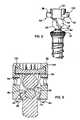
- FIG. 1is a perspective view of the spinal fixation system in accordance with the present invention showing a bone screw and a coupling device including a coupling member and a cam lock member for securing a spinal rod relative to the bone screw;
- FIG. 2is an enlarged perspective view of the spinal fixation system of FIG. 1 with the coupling member removed to better illustrate the cam lock member and to show the configuration of the head of the bone screw;
- FIG. 3is a cross-sectional view of the spinal fixation system showing a recess formed in the screw head in which a low profile anvil insert is received for clamping of the spinal rod thereagainst;
- FIG. 4is a cross-sectional view similar to FIG. 3 showing the relative sizes of the various components of the spinal fixation system
- FIG. 5is a elevational view similar to FIG. 2 with the coupling member removed to show the radial flanges on the cam lock member and a bottom cam surface thereof;
- FIG. 6is a cross-sectional view of the spinal fixation system showing the recesses formed in the coupling member configured to receive the radial flanges on the cam lock member;
- FIGS. 7–10are various views of the cam lock member
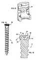
- FIGS. 11–13are various views of the yoke-shaped coupling member
- FIGS. 14 and 15are elevational and sectional views, respectively, of the bone screw anchor member.
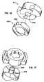
- FIGS. 16–18are various views of alternative camming system employing both a cam lock member and a saddle member.
- the spinal fixation system 10includes a bone anchor member in the form of a bone screw 12 and a coupling device generally designated 14 .
- the coupling device 14is operable to secure an elongate member in the form of spinal rod 16 in place relative to the bone screw 12 .
- the coupling device 14includes a compression or cam lock member 18 and a coupling member 20 , which cooperate to secure the spinal rod 16 relative to the bone screw 12 anchored in a vertebral bone with the rod 16 generally extending axially along the spinal column.
- the coupling device 14 and specifically the cam lock member 18 and coupling member 20are provided with a compact configuration.
- cam lock member 18 and coupling member 20are provided with a very low profile in a direction indicated by axis line 21 extending transverse and specifically orthogonally to the axis 16 a of the spinal rod 16 fixed relative to the bone screw 12 by the coupling device 14 , as best seen in FIG. 4 .
- the low profile of the coupling device 14is obtained by having the cam lock member 18 be effective to lock the spinal rod 16 without the need to advance the cam lock member 18 along the coupling member 20 .
- the coupling member 20can be provided with a body 22 having side openings 24 and 26 through which the spinal rod 16 passes with the body 22 free of any threading or cam surfaces that cooperate with the cam lock member 18 for locking of the spinal rod 16 relative to the bone screw 12 .
- the cam lock member 18is fixed against translation relative to the coupling member 20 , and preferably cooperates with the outer curved surface 28 of the rod 16 itself to secure it in position relative to the screw 12 .
- the cam lock member 18has a generally annularly configured body 30 having a very short axial extent along turning axis 21 thereof via annular side surface 31 extending between its top and bottom surfaces 32 and 34 .
- the top surface 32is provided with driving surface portions 36 which cooperate to form a predetermined configuration for the receipt of a similarly configured drive tool for turning the cap member 18 between unlocked and locked positions thereof.
- the bottom surface 34is programmed or contoured to provide a camming action on the curved surface 28 of the rod 16 when the cam lock member 18 is turned, as best seen in FIGS. 8 and 10 and as will be described more fully hereinafter.
- an intermediate saddle member 200can be provided between the lock member 18 and spinal rod 16 , as shown in FIGS. 16–18 .
- the saddle member 200has an upper cam surface 202 configured for cooperation with lock member cam surface 34 when the lock member 18 is turned to its locked position so that the saddle member 200 shifts downwardly along axis 21 for clamping against the rod 16 .
- the saddle memberis provided with a curved bottom surface 204 which substantially matches the curvature of rod surface 28 so that the saddle member 200 engages and pushes against the rod 16 without camming thereagainst.
- the cam lock member 18can include a center opening 206 which receives a central post 208 projecting upward from the saddle member 200 to keep the cam lock member 18 and saddle member 200 oriented properly with respect to each other.
- the coupling member 20also has a relatively small axial extent between top and bottom surfaces 38 and 40 thereof.
- the body 22 of the coupling membergenerally has a U-shaped or yoke configuration including opposing upstanding walls 42 and 44 spaced from each other by the rod openings 24 and 26 which can have an elongate configuration and be open to the top 38 of the coupling member body 22 . Since the cam lock member 18 need not be advanced down along the walls 42 and 44 in the direction 21 , the size in this direction can be minimized. By way of example and not limitation, the length or distance that the walls 42 and 44 extend between the top 38 and bottom 40 of the coupling member body 22 can be approximately 13.47 millimeters.
- the cam lock member 18has a profile along axis 21 between the top 32 and the lowest most point of the contoured bottom cam surface 34 of approximately 5.08 mm.
- the annular body 30 of cam lock member 18is sized to fit in internal space 46 of the coupling member 20 between the arcuate walls 42 and 44 thereof.
- the walls 42 and 44are free of threading or cam surfaces that cooperate with the cam lock member 18 for shifting it to a locked position.
- the inner surface 48 of the coupling member 20 including arcuate surface portions 42 a and 44 a on the respective coupling member walls 42 and 44are sized to closely receive the outer surface 31 of the cam lock member annular body 30 therebetween.
- These surface portions 42 a and 44 aare each free of threading or cam surfaces and thus only serve as guide surfaces for the cam lock member body 30 as it is turned about axis 21 .
- the size of the coupling device 14can be kept to a minimum in the widthwise direction along the axis 16 a of the spinal rod 16 as well.
- the diametrical width of the coupling device along spinal rod axis 16 acan be approximately 10.03 millimeters.
- guides 45may be provided. The guides 45 are provided to initially pilot the cam lock member 18 into engagement with the walls 42 and 44 .
- the illustrated spinal fixation system 10has a polyaxial bone screw 12 whose orientation can be changed such that its longitudinal axis 12 a extends transverse to the axis 21 of the coupling device 14 or is substantially aligned therewith.
- the coupling device 18and specifically the coupling member 20 thereof is provided with a bottom throughbore 50 that extends through bottom wall 52 of the coupling member 20 .
- the bottom wall 52includes an inner surface portion 54 that tapers or curves inwardly from the surface portions 42 a and 44 a toward the center axis 21 .
- the diameter across the inner surface portion 54 at its lowermost end 56is sized to be smaller than an enlarged head 58 of the bone anchor screw 12 .
- the diameter at 56is sufficiently large to allow the threaded shank 60 depending from the screw head 58 to be advanced therethrough.
- the inner surface portion 54serves as a seating surface for the screw head 58 .
- the diameter 56is threaded with a thread oversized relative to the shank 60 , thereby allowing the screw shank 60 to be loosely threaded through.
- the diameter 56is sized as to hold the shank 60 from passing easily through so that the screw 12 and coupling member 20 may be handled by a surgeon as a single component during the operation.
- the oversized threadsallow the screw to be polyaxial in its orientation.
- the screw 12may be passed through the diameter 56 , and a c-ring or radial spring may be attached to the screw 12 immediately adjacent to the coupling member 20 , thereby holding the two together and allowing the surgeon to utilize them as a single component during the operation.
- the throughbore 50extends centrally through the inner surface portion 54 and includes an enlarged diameter lower portion 62 formed by tapered or curved surface portion 64 on the bottom wall 52 of the coupling member 20 .
- the tapered surface portion 64extends from the smallest diameter of the bore 50 at 56 tapering outwardly relative to the center axis 21 of the coupling member 20 to the bottom surface 30 thereof.
- the enlarged bore portion 62allows the screw 12 to swivel or pivot to a variety of different orientations thereof relative to the coupling device 14 .
- the enlarged bore portion 62allows the screw shank to pivot by 20 degrees on either side of the coupling device axis 21 .
- the outer arcuate surface 66 of the screw head 58rides or shifts on the tapered seat surface 54 in the coupling member 20 .
- the cam lock member 18is then turned to its locked position. In the locked position, the cam lock member 18 anchors the rod 16 to the spinal column so it is fixed relative to the bone screw 12 fastened into a vertebral bone with the bone screw head 58 clamped against the seat 54 therefor in the coupling member 20 thereby fixing coupling device 14 against shifting relative to the bone screw 12 .
- the outer screw head surface 66can be configured with concentric friction enhancing ridges or helical threads 67 to enhance the locking action between the screw head 58 and the seat 54 .
- the spinal rod 16is pushed downwardly for being clamped against a small anvil insert 68 .
- the previously described low profile coupling device 14could be employed in spinal fixation systems that are not polyaxial and/or which do not employ an insert as described hereinafter.
- the present insert 68could be advantageously employed in systems that employ threads or cams in the coupling members thereof.
- the insert 68has an upper anvil surface 70 that engages against the underside of the spinal rod surface 28 to maintain enhanced contact therewith over the curved surfaces of bone screw heads used in prior systems.
- the insert 68has an upper surface 70 that may be substantially flat, may have radially oriented concave paths or valleys so that the insert 68 rotates to the closest path to meet with the spinal rod surface 28 , or may have a cup or peripheral ridge that deforms when compressed by the spinal rod 12 to form a path without deforming the spinal rod.
- the insert 68provides at least a line of contact with the curved rod surface 28 , whereas prior systems engaging spinal rods with their curved fastener heads have a point contact with the spinal rod when clamped thereagainst which can more easily damage the rod 16 .
- the present insert 68is also provided with a very low profile to minimize the space it takes up in the coupling member 20 .
- the bone screw anchor 12as an upper concave recess 72 formed in the screw head 58 thereof to form a cup-shaped wall 73 of the screw head 58 having an upwardly opening cavity 74 in which insert 68 is received.
- the insert 68has an arcuate bottom surface 76 having a curvature similar to that of the concave surface 72 so that it can shift or slide thereon as the polyaxial screw 12 is moved to various orientations thereof relative to the coupling device 14 .
- the insert 68is sized such that the distance between the lower most point of the bottom surface 76 and the top flat surface 70 is slightly larger than the depth of the cavity 74 .
- the insert 68only nominally increases the height of the screw head 58 in the internal space 46 of the coupling member 20 allowing the coupling device 14 to maintain its low profile character, as previously described.
- the distance between the bottom 40 of the coupling member 20 and the spinal rod axis 16 a with the rod 16 clamped against the insert 68can be approximately 6.34 millimeters.
- the insert 68has a greater elastic deformation than the coupling member 20 or the spinal rod 16 so that it has a greater spring-like property.
- the material of the insert 68preferably has a lower Young's Modulus than the coupling member 20 and spinal rod, thereby reducing the criticality of the dimensional tolerances.
- the small, low profile insert 68has an enlarged lower portion 82 including the arcuate bottom surface 76 thereon with an upper portion 84 projecting centrally upward from the enlarged lower portion 82 and having the top surface 70 thereon. Accordingly, the top surface 70 is narrower in the directions orthogonal to the axis 21 then the bottom surface 76 so that a shoulder surface 86 is formed between the insert portions 82 and 84 .
- the above-described structure for the low profile insert 68provides it with an inverted mushroom-like configuration with the enlarged head portion 82 riding on the concave recess surface 72 in the screw head 58 .
- a retainersuch as in the form of staked portions 86 of the screw head wall 73 are provided. These staked portions 86 extend radially inward at the proximal end 78 of the screw 12 so as to be in interference with the shoulder surface 86 on the insert 68 for keeping it retained in the cavity 74 , and in a substantially upright position while providing for a small amount of rotation therein as shown in FIGS. 3–6 . It should be noted that the term rotation is meant to include any pivoting of the insert within the screw head 58 . As can be seen, the insert 68 is not fixed with respect to the coupling member 20 , instead being retained in the screw head with the staked portions 86 .
- the insert 68may follow the rod surface 28 and seat itself between the rod surface 28 and the screw head 58 for a self-aligning capability.
- the cam lock member 18does not translate along the coupling member 20 when it is turned to its locked position.
- itis provided with real flanges 90 and 92 extending radially outwardly from the annular body 30 at diametrically opposite positions thereon.
- the flanges 90 and 92are received in correspondingly configured recesses 94 and 96 formed in the coupling member walls 42 and 44 , as can be seen in FIG. 6 .
- the recesses 94 and 96have an arcuate configuration extending about axis 21 as do the radial flanges 90 and 92 for fitting therein and allowing turning of the cam lock member 18 between unlocked and locked positions thereof.
- the flanges 90 and 92are received in the recesses 94 and 96 when the cam lock member 18 is turned toward its locked position. With the cam surface 34 camming on the rod surface 28 , the flanges 90 and 92 in the closely conforming recesses 94 and 96 prevent the cam lock member 18 from shifting upwardly away from the spinal rod 16 and instead forces the spinal rod 16 down into clamping engagement with the insert 68 which, in turn, causes the screw head 58 and specifically outer head surface 66 to be clamped against the seat surface 54 in the coupling member 20 thus fixing the coupling device 14 relative to the bone screw 12 and anchoring the spinal rod 16 to the spinal column.
- the flanges 90 and 92are also provided with distal portions 90 and 100 , respectively, that extend along axis 21 .
- the distal portions 98 and 100are shown as being upturned from the distal ends of the radial flanges 90 and 92 although they could likewise be configured so that they extend downwardly in the direction along axis 21 .
- the recesses 94 and 96also include portions 102 and 104 , respectively, that extend in an upward direction along the axis 21 in the coupler member walls 42 and 44 for receiving the upturned distal portions 98 and 100 on the respective radial flanges 90 and 92 . With the flange portions 98 and 100 received in the recess portions 102 and 104 , any spreading action of the walls 42 and 44 during the locking operation with turning of the cam lock member 18 is resisted.
- the cam lock memberhas a contoured bottom cam surface 34 that cams on the curved cam surface 28 of the spinal rod 16 .
- the cam surface 34is best seen in FIGS. 8 and 10 .
- the cam surface 34is contoured to provide three distinct regions defined in relation to their action on the spinal rod 16 .
- a first concave region 106is provided to substantially mate with the rod surface 28 in the unlocked position. Concave surface region 106 extends across the bottom 34 of the cam lock member body 30 and can be aligned with the radial flanges 90 and 92 .
- the radial flanges 90 and 92will be disposed slightly above the bottom 34 of the cam lock member body 30 to accommodate the spinal rod curved surface 28 extending therebelow with the cam lock member 18 in the unlocked position thereof. In this position, the flanges 90 and 92 are not received or fully received in the recesses 94 and 96 therefor.
- Diametrically opposite sections 106 a and 106 b of the concave surface region 106are provided so that rotation of the cam lock member 18 in the unlocked position does not cause a camming action to occur with only a slight initial turning action thereof.
- the spinal rod surface 106aligned with the surface portions 106 a and 106 b , the spinal rod 16 is still loosely received under the cam lock member 18 and is not cammed thereby.
- the spinal rod 16is captured under the cam lock member 18 so as to provide the surgeon with greater freedom of manipulation before finally locking the cam lock member 18 .
- the camming actionbegins at ramp regions 108 and 110 that are diametrically opposite to each other on the cap bottom surface 34 and project downwardly from the adjacent surface sections 106 a , 106 b along direction 21 .
- the ramp regions 108 and 110are configured so that the rod 16 is progressively pushed downward in the direction 21 as the cam lock member 18 is turned about the turning axis 21 toward the locked position. Accordingly, in the unlocked position these ramp surface regions 108 and 110 on the bottom cam surface 34 extend down along either side of the spinal rod 16 so as to advantageously take up the space on either side thereof thus serving to keep the space occupied by the cam lock member 18 in the coupling member 20 to a minimum for providing the overall coupling device 14 with a low profile.
- the surface regions 112 and 114may be a valley shape providing a depression such that the rod 12 is received into the depression.
- the surface regions 112 and 114are not inclined relative to the axis 21 like the preceding ramp surfaces 108 and 110 and are the lowest point of engagement of the cam surface 34 with the rod surface 28 .
- the illustrated and preferred programmed cam surface 34provides several stages for the camming and locking action on the spinal rod 16 .
- the cam lock member 18can be rotated by approximately 20 degrees from the unlocked position before the rod surface 28 reaches the ramp surfaces 108 and 110 .
- the rod 16is cammed downwardly and the cam lock member can be turned for another 60 degrees before the rod surface 28 reaches the flat locking surfaces 112 and 114 .
- the cam lock member 18can then be turned by another 20 degrees before the rod surface 28 abuts against the stop surfaces 116 and 118 and the cam lock member 18 is in its fully locked position.
- the cap cam lock member 18includes drive surface portion 36 recessed in the top surface 32 .
- the drive surface portion 36can be formed with a plurality of lobes extending radially outward from the center axis 21 for receiving a similarly lobed drive tool.
- the lobe drive surface portions 36provide an increased area for surface contact and torque transmission between the drive tool and the cam lock member 18 .
- the screw head 58is provided with peripheral driving surfaces 120 and recessed notches 122 formed in the proximal end 78 of the screw head and recessed or notched into the top surface 80 thereof, as can be seen in FIG. 15 .
- a driving toolhaving peripheral prongs for fitting in the notches 122 can be utilized while the anvil insert 68 is in the screw head cavity 74 and slightly projecting out therefrom, as previously described.
- the yoke coupler walls 42 and 44are provided with a key slot 124 and 126 , respectively, with the slots 124 and 126 having enlarged central throughbore 128 and 130 extending through the walls 42 and 44 .
- the slotsenable the coupling device 14 to be held as by arms on a device used to insert the spinal rod 16 into the coupling member 20 , e.g. a rod persuader.
- the armscan have engaging ends that locate in the slots 124 and 126 and extend into the throughbores 128 and 130 .
Landscapes
- Health & Medical Sciences (AREA)
- Orthopedic Medicine & Surgery (AREA)
- Life Sciences & Earth Sciences (AREA)
- Neurology (AREA)
- Surgery (AREA)
- Heart & Thoracic Surgery (AREA)
- Engineering & Computer Science (AREA)
- Biomedical Technology (AREA)
- Nuclear Medicine, Radiotherapy & Molecular Imaging (AREA)
- Medical Informatics (AREA)
- Molecular Biology (AREA)
- Animal Behavior & Ethology (AREA)
- General Health & Medical Sciences (AREA)
- Public Health (AREA)
- Veterinary Medicine (AREA)
- Surgical Instruments (AREA)
- Prostheses (AREA)
Abstract
Description
Claims (21)
Priority Applications (12)
| Application Number | Priority Date | Filing Date | Title |
|---|---|---|---|
| US10/358,530US7141051B2 (en) | 2003-02-05 | 2003-02-05 | Low profile spinal fixation system |
| GB0700065AGB2436005B (en) | 2003-02-05 | 2004-02-05 | Low profile spinal fixation system |
| US10/549,873US8075590B2 (en) | 2003-02-05 | 2004-02-05 | Low profile spinal fixation system |
| AU2004211957AAU2004211957A1 (en) | 2003-02-05 | 2004-02-05 | Low profile spinal fixation system |
| JP2006503408AJP4530178B2 (en) | 2003-02-05 | 2004-02-05 | Low dimension spinal fixation system |
| DE112004000251TDE112004000251T5 (en) | 2003-02-05 | 2004-02-05 | Low-profile spinal fixation system |
| PCT/US2004/003605WO2004071339A2 (en) | 2003-02-05 | 2004-02-05 | Low profile spinal fixation system |
| CNB2004800000152ACN100556380C (en) | 2003-02-05 | 2004-02-05 | Low Profile Spinal Fixation System |
| GB0517491AGB2414680B (en) | 2003-02-05 | 2004-02-05 | Low profile spinal fixation system |
| BR0407295-2ABRPI0407295A (en) | 2003-02-05 | 2004-02-05 | Spinal Fixation System |
| CA002515432ACA2515432A1 (en) | 2003-02-05 | 2004-02-05 | Low profile spinal fixation system |
| US12/067,616US8172876B2 (en) | 2003-02-05 | 2006-09-20 | Spinal fixation systems |
Applications Claiming Priority (1)
| Application Number | Priority Date | Filing Date | Title |
|---|---|---|---|
| US10/358,530US7141051B2 (en) | 2003-02-05 | 2003-02-05 | Low profile spinal fixation system |
Related Child Applications (1)
| Application Number | Title | Priority Date | Filing Date |
|---|---|---|---|
| US12/067,616Continuation-In-PartUS8172876B2 (en) | 2003-02-05 | 2006-09-20 | Spinal fixation systems |
Publications (2)
| Publication Number | Publication Date |
|---|---|
| US20040153068A1 US20040153068A1 (en) | 2004-08-05 |
| US7141051B2true US7141051B2 (en) | 2006-11-28 |
Family
ID=32771213
Family Applications (2)
| Application Number | Title | Priority Date | Filing Date |
|---|---|---|---|
| US10/358,530Expired - Fee RelatedUS7141051B2 (en) | 2003-02-05 | 2003-02-05 | Low profile spinal fixation system |
| US10/549,873Expired - Fee RelatedUS8075590B2 (en) | 2003-02-05 | 2004-02-05 | Low profile spinal fixation system |
Family Applications After (1)
| Application Number | Title | Priority Date | Filing Date |
|---|---|---|---|
| US10/549,873Expired - Fee RelatedUS8075590B2 (en) | 2003-02-05 | 2004-02-05 | Low profile spinal fixation system |
Country Status (9)
| Country | Link |
|---|---|
| US (2) | US7141051B2 (en) |
| JP (1) | JP4530178B2 (en) |
| CN (1) | CN100556380C (en) |
| AU (1) | AU2004211957A1 (en) |
| BR (1) | BRPI0407295A (en) |
| CA (1) | CA2515432A1 (en) |
| DE (1) | DE112004000251T5 (en) |
| GB (1) | GB2414680B (en) |
| WO (1) | WO2004071339A2 (en) |
Cited By (153)
| Publication number | Priority date | Publication date | Assignee | Title |
|---|---|---|---|---|
| US20050228385A1 (en)* | 2004-04-08 | 2005-10-13 | Globus Medical Inc. | Polyaxial screw |
| US20060004359A1 (en)* | 2002-09-04 | 2006-01-05 | Aesculap Ag & Co. Kg | Orthopedic fixation device |
| US20060004363A1 (en)* | 2004-05-25 | 2006-01-05 | University Of Utah Research Foundation | Occipitocervical plate |
| US20060149233A1 (en)* | 2004-12-16 | 2006-07-06 | Richelsoph Marc E | Locking mechanism |
| US20070016192A1 (en)* | 2005-05-04 | 2007-01-18 | Woods Richard W | Polyaxial surgical rod fixation assembly |
| US20070083199A1 (en)* | 2003-09-04 | 2007-04-12 | Abbott Spine | Spinal implant |
| US20070093827A1 (en)* | 2005-10-04 | 2007-04-26 | Warnick David R | Pedicle screw system with provisional locking aspects |
| US20070123872A1 (en)* | 2004-05-25 | 2007-05-31 | University Of Utah Research Foundation | Occipitocervical plate |
| US20070123862A1 (en)* | 2004-10-25 | 2007-05-31 | Warnick David R | Bone fixation system and method for using the same |
| US20070191844A1 (en)* | 2006-01-31 | 2007-08-16 | Sdgi Holdings, Inc. | In-series, dual locking mechanism device |
| US20070208344A1 (en)* | 2006-03-01 | 2007-09-06 | Sdgi Holdings, Inc. | Devices for securing elongated spinal connecting elements in bone anchors |
| US20070212915A1 (en)* | 2006-03-07 | 2007-09-13 | Strnad Lee A | Variable axis locking mechanism for use in orthopedic implants |
| US20070233069A1 (en)* | 2006-02-27 | 2007-10-04 | Stewart Young | Implant/support member interconnection mechanism |
| US20080039840A1 (en)* | 2005-02-23 | 2008-02-14 | Pioneer Laboratories, Inc. | Minimally invasive surgical system |
| US20080125813A1 (en)* | 2006-09-21 | 2008-05-29 | Warsaw Orthopedic, Inc. | Low profile vertebral stabilization systems and methods |
| US20080200956A1 (en)* | 2007-02-19 | 2008-08-21 | Tutela Medicus, Llc | Low Profile Orthopedic Fastener Assembly Having Enhanced Flexibility |
| WO2009038697A1 (en)* | 2007-09-17 | 2009-03-26 | Jackson Roger P | Polyaxial bone anchor assembly with one-piece closure, pressure insert and plastic elongate member |
| US20090082819A1 (en)* | 2007-06-28 | 2009-03-26 | Spinal Elements, Inc. | Spinal stabilization device |
| US20090088800A1 (en)* | 2007-08-24 | 2009-04-02 | Spinal Elements, Inc. | Loop rod spinal stablization device |
| US20090318969A1 (en)* | 2008-06-19 | 2009-12-24 | Wilfried Matthis | Bone anchoring assembly |
| US20090318973A1 (en)* | 2006-05-30 | 2009-12-24 | Jean-Pierre Moulin | Bone fixing device |
| USD607103S1 (en)* | 2008-10-22 | 2009-12-29 | Ulrich Gmbh & Co. Kg | Medical implant |
| US20100030135A1 (en)* | 2006-05-11 | 2010-02-04 | Michael David Mitchell | Method and apparatus for anchoring bone screws and injecting many types of high viscosity materials in areas surrounding bone |
| US20100036433A1 (en)* | 2005-07-14 | 2010-02-11 | Jackson Roger P | Polyaxial Bone screw assembly with fixed retaining structure |
| US7662172B2 (en) | 2004-10-25 | 2010-02-16 | X-Spine Systems, Inc. | Pedicle screw systems and methods of assembling/installing the same |
| US20100057126A1 (en)* | 2008-09-04 | 2010-03-04 | Zimmer Spine, Inc. | Dynamic vertebral fastener |
| US7717943B2 (en) | 2005-07-29 | 2010-05-18 | X-Spine Systems, Inc. | Capless multiaxial screw and spinal fixation assembly and method |
| US7722652B2 (en) | 2006-01-27 | 2010-05-25 | Warsaw Orthopedic, Inc. | Pivoting joints for spinal implants including designed resistance to motion and methods of use |
| US20100160978A1 (en)* | 2008-12-23 | 2010-06-24 | John Carbone | Bone screw assembly with non-uniform material |
| US20100256681A1 (en)* | 2004-08-27 | 2010-10-07 | Hammer Michael A | Multi-axial connection system |
| US7833252B2 (en) | 2006-01-27 | 2010-11-16 | Warsaw Orthopedic, Inc. | Pivoting joints for spinal implants including designed resistance to motion and methods of use |
| US20110015682A1 (en)* | 2009-07-15 | 2011-01-20 | Orthohelix Surgical Designs, Inc. | Variable axis locking mechanism for use in orthopedic implants |
| US7875065B2 (en) | 2004-11-23 | 2011-01-25 | Jackson Roger P | Polyaxial bone screw with multi-part shank retainer and pressure insert |
| US7955363B2 (en) | 2002-04-18 | 2011-06-07 | Aesculap Implant Systems, Llc | Screw and rod fixation assembly and device |
| US7967850B2 (en) | 2003-06-18 | 2011-06-28 | Jackson Roger P | Polyaxial bone anchor with helical capture connection, insert and dual locking assembly |
| US20110190824A1 (en)* | 2010-01-26 | 2011-08-04 | Gephart Matthew P | Occipital Plate for Spinal Fusion |
| US20110202096A1 (en)* | 2010-02-12 | 2011-08-18 | John White | Spinal Rod and Screw Securing Apparatus and Method |
| US20110224737A1 (en)* | 2010-03-10 | 2011-09-15 | Orthohelix Surgical Designs, Inc. | System for achieving selectable fixation in an orthopedic plate |
| US8057519B2 (en) | 2006-01-27 | 2011-11-15 | Warsaw Orthopedic, Inc. | Multi-axial screw assembly |
| US8066739B2 (en) | 2004-02-27 | 2011-11-29 | Jackson Roger P | Tool system for dynamic spinal implants |
| US8097025B2 (en) | 2005-10-25 | 2012-01-17 | X-Spine Systems, Inc. | Pedicle screw system configured to receive a straight or curved rod |
| US8096996B2 (en) | 2007-03-20 | 2012-01-17 | Exactech, Inc. | Rod reducer |
| US8100915B2 (en) | 2004-02-27 | 2012-01-24 | Jackson Roger P | Orthopedic implant rod reduction tool set and method |
| US8105368B2 (en) | 2005-09-30 | 2012-01-31 | Jackson Roger P | Dynamic stabilization connecting member with slitted core and outer sleeve |
| US8137386B2 (en) | 2003-08-28 | 2012-03-20 | Jackson Roger P | Polyaxial bone screw apparatus |
| US20120071926A1 (en)* | 2010-09-16 | 2012-03-22 | Jani Mehul R | Transverse Connector |
| US8152810B2 (en) | 2004-11-23 | 2012-04-10 | Jackson Roger P | Spinal fixation tool set and method |
| US8197517B1 (en) | 2007-05-08 | 2012-06-12 | Theken Spine, Llc | Frictional polyaxial screw assembly |
| US8226690B2 (en) | 2005-07-22 | 2012-07-24 | The Board Of Trustees Of The Leland Stanford Junior University | Systems and methods for stabilization of bone structures |
| US8236035B1 (en) | 2009-06-16 | 2012-08-07 | Bedor Bernard M | Spinal fixation system and method |
| US8241341B2 (en) | 2009-03-20 | 2012-08-14 | Spinal Usa, Inc. | Pedicle screws and methods of using the same |
| US8257398B2 (en) | 2003-06-18 | 2012-09-04 | Jackson Roger P | Polyaxial bone screw with cam capture |
| US8257396B2 (en) | 2003-06-18 | 2012-09-04 | Jackson Roger P | Polyaxial bone screw with shank-retainer inset capture |
| US20120226325A1 (en)* | 2011-03-04 | 2012-09-06 | Warsaw Orthopedic, Inc. | Fastener Element Retention Feature for Bone Anchors |
| US8267969B2 (en)* | 2004-10-20 | 2012-09-18 | Exactech, Inc. | Screw systems and methods for use in stabilization of bone structures |
| US8292934B2 (en) | 2008-10-17 | 2012-10-23 | Warsaw Orthopedic, Inc. | Dynamic anchor assembly for connecting elements in spinal surgical procedures |
| US20120271354A1 (en)* | 2010-01-06 | 2012-10-25 | Implanet, Societe Anonyme | Vertebral attachment device |
| US8308782B2 (en) | 2004-11-23 | 2012-11-13 | Jackson Roger P | Bone anchors with longitudinal connecting member engaging inserts and closures for fixation and optional angulation |
| US8366745B2 (en) | 2007-05-01 | 2013-02-05 | Jackson Roger P | Dynamic stabilization assembly having pre-compressed spacers with differential displacements |
| US8377102B2 (en) | 2003-06-18 | 2013-02-19 | Roger P. Jackson | Polyaxial bone anchor with spline capture connection and lower pressure insert |
| US8394133B2 (en) | 2004-02-27 | 2013-03-12 | Roger P. Jackson | Dynamic fixation assemblies with inner core and outer coil-like member |
| US8398682B2 (en) | 2003-06-18 | 2013-03-19 | Roger P. Jackson | Polyaxial bone screw assembly |
| US8444681B2 (en) | 2009-06-15 | 2013-05-21 | Roger P. Jackson | Polyaxial bone anchor with pop-on shank, friction fit retainer and winged insert |
| US8475498B2 (en) | 2007-01-18 | 2013-07-02 | Roger P. Jackson | Dynamic stabilization connecting member with cord connection |
| US20130172937A1 (en)* | 2011-12-19 | 2013-07-04 | Amendia, Inc. | Extended tab bone screw system |
| US8523865B2 (en) | 2005-07-22 | 2013-09-03 | Exactech, Inc. | Tissue splitter |
| US8545538B2 (en) | 2005-12-19 | 2013-10-01 | M. Samy Abdou | Devices and methods for inter-vertebral orthopedic device placement |
| US8551141B2 (en) | 2006-08-23 | 2013-10-08 | Pioneer Surgical Technology, Inc. | Minimally invasive surgical system |
| US8556938B2 (en) | 2009-06-15 | 2013-10-15 | Roger P. Jackson | Polyaxial bone anchor with non-pivotable retainer and pop-on shank, some with friction fit |
| US8591515B2 (en) | 2004-11-23 | 2013-11-26 | Roger P. Jackson | Spinal fixation tool set and method |
| US8591560B2 (en) | 2005-09-30 | 2013-11-26 | Roger P. Jackson | Dynamic stabilization connecting member with elastic core and outer sleeve |
| US8790374B2 (en) | 2004-04-08 | 2014-07-29 | Globus Medical, Inc. | Polyaxial screw |
| US8814911B2 (en) | 2003-06-18 | 2014-08-26 | Roger P. Jackson | Polyaxial bone screw with cam connection and lock and release insert |
| US8814913B2 (en) | 2002-09-06 | 2014-08-26 | Roger P Jackson | Helical guide and advancement flange with break-off extensions |
| US20140249590A1 (en)* | 2005-04-25 | 2014-09-04 | Depuy Synthes Products Llc | Bone anchor with locking cap and method of spinal fixation |
| US20140257400A1 (en)* | 2013-03-05 | 2014-09-11 | Milan George | Elastic Member Clamps |
| US8845649B2 (en) | 2004-09-24 | 2014-09-30 | Roger P. Jackson | Spinal fixation tool set and method for rod reduction and fastener insertion |
| US8888827B2 (en) | 2011-07-15 | 2014-11-18 | Globus Medical, Inc. | Orthopedic fixation devices and methods of installation thereof |
| US8911479B2 (en) | 2012-01-10 | 2014-12-16 | Roger P. Jackson | Multi-start closures for open implants |
| US8936623B2 (en) | 2003-06-18 | 2015-01-20 | Roger P. Jackson | Polyaxial bone screw assembly |
| US8979904B2 (en) | 2007-05-01 | 2015-03-17 | Roger P Jackson | Connecting member with tensioned cord, low profile rigid sleeve and spacer with torsion control |
| US8998959B2 (en) | 2009-06-15 | 2015-04-07 | Roger P Jackson | Polyaxial bone anchors with pop-on shank, fully constrained friction fit retainer and lock and release insert |
| US9050139B2 (en) | 2004-02-27 | 2015-06-09 | Roger P. Jackson | Orthopedic implant rod reduction tool set and method |
| US9084634B1 (en) | 2010-07-09 | 2015-07-21 | Theken Spine, Llc | Uniplanar screw |
| US9131962B2 (en) | 2011-05-24 | 2015-09-15 | Globus Medical, Inc. | Bone screw assembly |
| US9168069B2 (en) | 2009-06-15 | 2015-10-27 | Roger P. Jackson | Polyaxial bone anchor with pop-on shank and winged insert with lower skirt for engaging a friction fit retainer |
| US9186187B2 (en) | 2011-07-15 | 2015-11-17 | Globus Medical, Inc. | Orthopedic fixation devices and methods of installation thereof |
| US9198694B2 (en) | 2011-07-15 | 2015-12-01 | Globus Medical, Inc. | Orthopedic fixation devices and methods of installation thereof |
| US9216041B2 (en) | 2009-06-15 | 2015-12-22 | Roger P. Jackson | Spinal connecting members with tensioned cords and rigid sleeves for engaging compression inserts |
| US9216039B2 (en) | 2004-02-27 | 2015-12-22 | Roger P. Jackson | Dynamic spinal stabilization assemblies, tool set and method |
| US9271759B2 (en) | 2012-03-09 | 2016-03-01 | Institute Of Musculoskeletal Science And Education, Ltd. | Pedicle screw assembly with locking cap |
| US9358047B2 (en) | 2011-07-15 | 2016-06-07 | Globus Medical, Inc. | Orthopedic fixation devices and methods of installation thereof |
| US9381044B2 (en) | 2010-01-26 | 2016-07-05 | Pioneer Surgical Technology, Inc. | Posterior spinal stabilization plate device |
| US9414863B2 (en) | 2005-02-22 | 2016-08-16 | Roger P. Jackson | Polyaxial bone screw with spherical capture, compression insert and alignment and retention structures |
| US9451989B2 (en) | 2007-01-18 | 2016-09-27 | Roger P Jackson | Dynamic stabilization members with elastic and inelastic sections |
| US9480517B2 (en) | 2009-06-15 | 2016-11-01 | Roger P. Jackson | Polyaxial bone anchor with pop-on shank, shank, friction fit retainer, winged insert and low profile edge lock |
| US9655665B2 (en) | 2007-07-03 | 2017-05-23 | Pioneer Surgical Technology, Inc. | Bone plate systems |
| US9707100B2 (en) | 2015-06-25 | 2017-07-18 | Institute for Musculoskeletal Science and Education, Ltd. | Interbody fusion device and system for implantation |
| US9743957B2 (en) | 2004-11-10 | 2017-08-29 | Roger P. Jackson | Polyaxial bone screw with shank articulation pressure insert and method |
| US9907574B2 (en) | 2008-08-01 | 2018-03-06 | Roger P. Jackson | Polyaxial bone anchors with pop-on shank, friction fit fully restrained retainer, insert and tool receiving features |
| US9942511B2 (en) | 2005-10-31 | 2018-04-10 | Invention Science Fund I, Llc | Preservation/degradation of video/audio aspects of a data stream |
| US9980753B2 (en) | 2009-06-15 | 2018-05-29 | Roger P Jackson | pivotal anchor with snap-in-place insert having rotation blocking extensions |
| US9993269B2 (en) | 2011-07-15 | 2018-06-12 | Globus Medical, Inc. | Orthopedic fixation devices and methods of installation thereof |
| US10039578B2 (en) | 2003-12-16 | 2018-08-07 | DePuy Synthes Products, Inc. | Methods and devices for minimally invasive spinal fixation element placement |
| US10159514B2 (en) | 2011-12-23 | 2018-12-25 | Pioneer Surgical Technology, Inc. | Method of implanting a bone plate |
| US10188431B2 (en) | 2015-12-17 | 2019-01-29 | Deniz Ufuk Erbulut | Double-headed pedicle screw |
| US10194951B2 (en) | 2005-05-10 | 2019-02-05 | Roger P. Jackson | Polyaxial bone anchor with compound articulation and pop-on shank |
| US10226291B2 (en) | 2007-07-03 | 2019-03-12 | Pioneer Surgical Technology, Inc. | Bone plate system |
| US10258382B2 (en) | 2007-01-18 | 2019-04-16 | Roger P. Jackson | Rod-cord dynamic connection assemblies with slidable bone anchor attachment members along the cord |
| US10265104B2 (en) | 2015-09-23 | 2019-04-23 | Deniz Ufuk Erbulut | Pedicle screw |
| US10299839B2 (en) | 2003-12-16 | 2019-05-28 | Medos International Sárl | Percutaneous access devices and bone anchor assemblies |
| US10363070B2 (en) | 2009-06-15 | 2019-07-30 | Roger P. Jackson | Pivotal bone anchor assemblies with pressure inserts and snap on articulating retainers |
| US20190239930A1 (en)* | 2003-05-22 | 2019-08-08 | Alphatec Spine, Inc. | Spinal screw assembly with snap-in-place bushing above a shank head hemisphere |
| US10383660B2 (en) | 2007-05-01 | 2019-08-20 | Roger P. Jackson | Soft stabilization assemblies with pretensioned cords |
| US10485588B2 (en) | 2004-02-27 | 2019-11-26 | Nuvasive, Inc. | Spinal fixation tool attachment structure |
| US10507043B1 (en) | 2017-10-11 | 2019-12-17 | Seaspine Orthopedics Corporation | Collet for a polyaxial screw assembly |
| US10543107B2 (en) | 2009-12-07 | 2020-01-28 | Samy Abdou | Devices and methods for minimally invasive spinal stabilization and instrumentation |
| US10548740B1 (en) | 2016-10-25 | 2020-02-04 | Samy Abdou | Devices and methods for vertebral bone realignment |
| US10575961B1 (en) | 2011-09-23 | 2020-03-03 | Samy Abdou | Spinal fixation devices and methods of use |
| US10603083B1 (en) | 2010-07-09 | 2020-03-31 | Theken Spine, Llc | Apparatus and method for limiting a range of angular positions of a screw |
| US10687855B2 (en) | 2012-11-21 | 2020-06-23 | Roger P. Jackson | Bone anchor receiver with extension portions having controlled splay allowance helically wound flange forms |
| US10695105B2 (en) | 2012-08-28 | 2020-06-30 | Samy Abdou | Spinal fixation devices and methods of use |
| US10729469B2 (en) | 2006-01-09 | 2020-08-04 | Roger P. Jackson | Flexible spinal stabilization assembly with spacer having off-axis core member |
| US10857003B1 (en) | 2015-10-14 | 2020-12-08 | Samy Abdou | Devices and methods for vertebral stabilization |
| US10918498B2 (en) | 2004-11-24 | 2021-02-16 | Samy Abdou | Devices and methods for inter-vertebral orthopedic device placement |
| US10925647B2 (en) | 2000-12-08 | 2021-02-23 | Roger P. Jackson | Threaded closure with inwardly-facing tool engaging concave radiused structures and axial through-aperture |
| US10973648B1 (en) | 2016-10-25 | 2021-04-13 | Samy Abdou | Devices and methods for vertebral bone realignment |
| US11006982B2 (en) | 2012-02-22 | 2021-05-18 | Samy Abdou | Spinous process fixation devices and methods of use |
| US11147591B2 (en) | 2004-11-10 | 2021-10-19 | Roger P Jackson | Pivotal bone anchor receiver assembly with threaded closure |
| US11173040B2 (en) | 2012-10-22 | 2021-11-16 | Cogent Spine, LLC | Devices and methods for spinal stabilization and instrumentation |
| US11179248B2 (en) | 2018-10-02 | 2021-11-23 | Samy Abdou | Devices and methods for spinal implantation |
| US11224464B2 (en) | 2002-05-09 | 2022-01-18 | Roger P. Jackson | Threaded closure with inwardly-facing tool engaging concave radiused structures and axial through-aperture |
| US11241261B2 (en) | 2005-09-30 | 2022-02-08 | Roger P Jackson | Apparatus and method for soft spinal stabilization using a tensionable cord and releasable end structure |
| US11364055B2 (en) | 2020-09-02 | 2022-06-21 | Zavation, Llc | Occipital plate and hinged rod assembly |
| US11419642B2 (en) | 2003-12-16 | 2022-08-23 | Medos International Sarl | Percutaneous access devices and bone anchor assemblies |
| US11627995B2 (en) | 2020-12-21 | 2023-04-18 | Warsaw Orthopedic, Inc. | Locking-cap module and connector |
| US11627992B2 (en) | 2020-12-21 | 2023-04-18 | Warsaw Orthopedic, Inc. | Locking-cap module and connector |
| US11690652B1 (en) | 2022-08-17 | 2023-07-04 | Zavation Medical Products Llc | Modular screw assembly |
| US11872143B2 (en) | 2016-10-25 | 2024-01-16 | Camber Spine Technologies, LLC | Spinal fusion implant |
| US11877935B2 (en) | 2016-10-18 | 2024-01-23 | Camber Spine Technologies, LLC | Implant with deployable blades |
| US11877779B2 (en) | 2020-03-26 | 2024-01-23 | Xtant Medical Holdings, Inc. | Bone plate system |
| US11957391B2 (en) | 2021-11-01 | 2024-04-16 | Warsaw Orthopedic, Inc. | Bone screw having an overmold of a shank |
| US11998247B2 (en) | 2009-06-15 | 2024-06-04 | Roger P. Jackson | Method of assembling a pivotal bone anchor assembly using insert tool deployment |
| US12042185B2 (en) | 2010-05-14 | 2024-07-23 | Roger P. Jackson | Pivotal bone anchor assembly with resiliently biased friction fit insert |
| US12053217B2 (en) | 2019-12-17 | 2024-08-06 | Roger P. Jackson | Receiver assembly with rotation blocking side pockets for twist-in-place insert and method of assembly |
| US12070249B2 (en) | 2014-06-04 | 2024-08-27 | Jackson Roger P | Pivotal bone anchor assembly with bottom loaded shank head engaging retainer and closure engaging insert |
| US12082853B2 (en) | 2014-10-21 | 2024-09-10 | Roger P. Jackson | Pivotal bone anchor assembly with positioner-retainer containment and insert tool deployment |
| US12096964B2 (en) | 2021-07-09 | 2024-09-24 | Roger P. Jackson | Modular bone anchor system with bottom loaded shank heads having a single shank head shape |
| US12102357B2 (en) | 2005-02-22 | 2024-10-01 | Roger P. Jackson | Pivotal bone anchor assembly with cannulated shank having a planar top surface and method of assembly |
| US12137945B2 (en) | 2018-09-13 | 2024-11-12 | Roger P. Jackson | Pivotal bone anchor system with modular receiver sub-assemblies and universal bone anchors |
| US12251138B2 (en) | 2014-10-21 | 2025-03-18 | Roger P. Jackson | Pivotal bone anchor assembly with biasing members for pre-lock friction fit |
| US12357348B2 (en) | 2005-09-30 | 2025-07-15 | Roger P. Jackson | Method of assembling a pivotal bone anchor assembly with press-in-place insert |
| US12440245B2 (en) | 2023-09-06 | 2025-10-14 | Pivotable bone anchor assembly with independent provisional locking by insert compressing member |
Families Citing this family (69)
| Publication number | Priority date | Publication date | Assignee | Title |
|---|---|---|---|---|
| US20160242816A9 (en)* | 2001-05-09 | 2016-08-25 | Roger P. Jackson | Dynamic spinal stabilization assembly with elastic bumpers and locking limited travel closure mechanisms |
| FR2829014B1 (en)* | 2001-09-03 | 2005-04-08 | Stryker Spine | SPINAL OSTEOSYNTHESIS SYSTEM COMPRISING A SUPPORT SKATE |
| US7066937B2 (en)* | 2002-02-13 | 2006-06-27 | Endius Incorporated | Apparatus for connecting a longitudinal member to a bone portion |
| US7879075B2 (en) | 2002-02-13 | 2011-02-01 | Zimmer Spine, Inc. | Methods for connecting a longitudinal member to a bone portion |
| US8876868B2 (en) | 2002-09-06 | 2014-11-04 | Roger P. Jackson | Helical guide and advancement flange with radially loaded lip |
| US20060200128A1 (en)* | 2003-04-04 | 2006-09-07 | Richard Mueller | Bone anchor |
| US8540753B2 (en) | 2003-04-09 | 2013-09-24 | Roger P. Jackson | Polyaxial bone screw with uploaded threaded shank and method of assembly and use |
| US7087057B2 (en) | 2003-06-27 | 2006-08-08 | Depuy Acromed, Inc. | Polyaxial bone screw |
| US7678137B2 (en) | 2004-01-13 | 2010-03-16 | Life Spine, Inc. | Pedicle screw constructs for spine fixation systems |
| US8951290B2 (en) | 2004-08-27 | 2015-02-10 | Blackstone Medical, Inc. | Multi-axial connection system |
| US8926672B2 (en) | 2004-11-10 | 2015-01-06 | Roger P. Jackson | Splay control closure for open bone anchor |
| US7445627B2 (en)* | 2005-01-31 | 2008-11-04 | Alpinespine, Llc | Polyaxial pedicle screw assembly |
| US7901437B2 (en) | 2007-01-26 | 2011-03-08 | Jackson Roger P | Dynamic stabilization member with molded connection |
| US7338491B2 (en)* | 2005-03-22 | 2008-03-04 | Spinefrontier Inc | Spinal fixation locking mechanism |
| US7909826B2 (en)* | 2005-03-24 | 2011-03-22 | Depuy Spine, Inc. | Low profile spinal tethering methods |
| WO2006127720A1 (en)* | 2005-05-25 | 2006-11-30 | Warsaw Orthopedic, Inc. | Dual anchor spinal implant apparatus |
| KR100741293B1 (en)* | 2005-08-30 | 2007-07-23 | 주식회사 솔고 바이오메디칼 | Spinal Pedicle Screw |
| DE502006002049D1 (en)* | 2005-09-13 | 2008-12-24 | Bird Biedermann Ag | Dynamic clamping device for spinal implant |
| US7955358B2 (en) | 2005-09-19 | 2011-06-07 | Albert Todd J | Bone screw apparatus, system and method |
| US20080140076A1 (en)* | 2005-09-30 | 2008-06-12 | Jackson Roger P | Dynamic stabilization connecting member with slitted segment and surrounding external elastomer |
| WO2007114834A1 (en)* | 2006-04-05 | 2007-10-11 | Dong Myung Jeon | Multi-axial, double locking bone screw assembly |
| WO2007121271A2 (en) | 2006-04-11 | 2007-10-25 | Synthes (U.S.A) | Minimally invasive fixation system |
| US8216240B2 (en)* | 2006-04-24 | 2012-07-10 | Warsaw Orthopedic | Cam based reduction instrument |
| JP5178717B2 (en)* | 2006-07-27 | 2013-04-10 | ジンテス ゲゼルシャフト ミット ベシュレンクテル ハフツング | Outrigger |
| US8894661B2 (en) | 2007-08-16 | 2014-11-25 | Smith & Nephew, Inc. | Helicoil interference fixation system for attaching a graft ligament to a bone |
| US20080195155A1 (en)* | 2007-02-12 | 2008-08-14 | Jeffrey Hoffman | Locking instrument for implantable fixation device |
| US20080312697A1 (en)* | 2007-06-15 | 2008-12-18 | Robert Reid, Inc. | System and Method for Polyaxially Adjustable Bone Anchorage |
| CA2694010C (en)* | 2007-07-19 | 2015-04-21 | Synthes Usa, Llc | Clamps used for interconnecting a bone anchor to a rod |
| PL2170192T3 (en)* | 2007-07-20 | 2011-07-29 | Synthes Gmbh | Polyaxial bone fixation element |
| US20090105756A1 (en)* | 2007-10-23 | 2009-04-23 | Marc Richelsoph | Spinal implant |
| US20090112209A1 (en)* | 2007-10-31 | 2009-04-30 | Zimmer, Inc. | Implantation system for intramedullary nail and related methods for implanting intramedullary nails |
| US20090182384A1 (en)* | 2008-01-14 | 2009-07-16 | Warsaw Orthopedic, Inc. | Material combinations for medical device implants |
| WO2009124196A2 (en)* | 2008-04-03 | 2009-10-08 | Life Spine, Inc. | Top loading polyaxial spine screw assembly with one step lockup |
| US20090299375A1 (en)* | 2008-06-03 | 2009-12-03 | Zimmer, Inc. | Catheter nail targeting guide |
| US20100004693A1 (en)* | 2008-07-01 | 2010-01-07 | Peter Thomas Miller | Cam locking spine stabilization system and method |
| US8118837B2 (en)* | 2008-07-03 | 2012-02-21 | Zimmer Spine, Inc. | Tapered-lock spinal rod connectors and methods for use |
| US8167914B1 (en) | 2008-07-16 | 2012-05-01 | Zimmer Spine, Inc. | Locking insert for spine stabilization and method of use |
| US8197512B1 (en) | 2008-07-16 | 2012-06-12 | Zimmer Spine, Inc. | System and method for spine stabilization using resilient inserts |
| USD601702S1 (en)* | 2008-08-14 | 2009-10-06 | Yechiel Gotfried | Surgical instrument |
| US9603629B2 (en) | 2008-09-09 | 2017-03-28 | Intelligent Implant Systems Llc | Polyaxial screw assembly |
| CN102497828B (en) | 2009-05-20 | 2015-09-09 | 斯恩蒂斯有限公司 | What patient installed retracts part |
| US9668771B2 (en) | 2009-06-15 | 2017-06-06 | Roger P Jackson | Soft stabilization assemblies with off-set connector |
| US8657856B2 (en) | 2009-08-28 | 2014-02-25 | Pioneer Surgical Technology, Inc. | Size transition spinal rod |
| US9044272B2 (en) | 2009-11-09 | 2015-06-02 | Ebi, Llc | Multiplanar bone anchor system |
| WO2011063410A1 (en)* | 2009-11-23 | 2011-05-26 | Felix Quevedo | Cam lock pedicle screw |
| US9775702B2 (en) | 2010-03-10 | 2017-10-03 | Smith & Nephew, Inc. | Composite interference screws and drivers |
| US9579188B2 (en) | 2010-03-10 | 2017-02-28 | Smith & Nephew, Inc. | Anchor having a controlled driver orientation |
| US8979865B2 (en) | 2010-03-10 | 2015-03-17 | Smith & Nephew, Inc. | Composite interference screws and drivers |
| US9308080B2 (en) | 2010-03-10 | 2016-04-12 | Smith & Nephew Inc. | Composite interference screws and drivers |
| FR2959113B1 (en)* | 2010-04-23 | 2013-04-12 | Smartspine | POLAR PEDICULAR SCREW AND PEDICULAR FIXING DEVICE FOR APPLYING FOR VERTEBRAL OSTEOSYNTHESIS |
| US8535318B2 (en) | 2010-04-23 | 2013-09-17 | DePuy Synthes Products, LLC | Minimally invasive instrument set, devices and related methods |
| EP2637584A4 (en)* | 2010-10-15 | 2015-01-28 | Alphatec Holdings Inc | FIXING SCREW ASSEMBLY |
| US8337530B2 (en)* | 2011-03-09 | 2012-12-25 | Zimmer Spine, Inc. | Polyaxial pedicle screw with increased angulation |
| MX344606B (en) | 2011-03-11 | 2016-12-20 | Smith & Nephew Inc | Trephine. |
| CN103717159B (en) | 2011-05-27 | 2016-08-17 | 新特斯有限责任公司 | Minimally Invasive Spinal Fixation System Including Vertebral Alignment Features |
| AU2012267924B2 (en) | 2011-06-07 | 2016-08-11 | Smith & Nephew, Inc. | Surgical anchor delivery system |
| US10058354B2 (en) | 2013-01-28 | 2018-08-28 | Roger P. Jackson | Pivotal bone anchor assembly with frictional shank head seating surfaces |
| US8852239B2 (en) | 2013-02-15 | 2014-10-07 | Roger P Jackson | Sagittal angle screw with integral shank and receiver |
| US9155531B2 (en) | 2013-03-15 | 2015-10-13 | Smith & Nephew, Inc. | Miniaturized dual drive open architecture suture anchor |
| WO2014169058A1 (en) | 2013-04-09 | 2014-10-16 | Smith & Nephew, Inc | Open-architecture interference screw |
| US9044273B2 (en) | 2013-10-07 | 2015-06-02 | Intelligent Implant Systems, Llc | Polyaxial plate rod system and surgical procedure |
| US9566092B2 (en) | 2013-10-29 | 2017-02-14 | Roger P. Jackson | Cervical bone anchor with collet retainer and outer locking sleeve |
| US9717533B2 (en) | 2013-12-12 | 2017-08-01 | Roger P. Jackson | Bone anchor closure pivot-splay control flange form guide and advancement structure |
| US9451993B2 (en) | 2014-01-09 | 2016-09-27 | Roger P. Jackson | Bi-radial pop-on cervical bone anchor |
| US9597119B2 (en) | 2014-06-04 | 2017-03-21 | Roger P. Jackson | Polyaxial bone anchor with polymer sleeve |
| US10786289B2 (en)* | 2014-07-16 | 2020-09-29 | The Regents Of The University Of Colorado A Body Corporate | System and methods for positioning of two or more interacting elements |
| WO2016172677A1 (en)* | 2015-04-24 | 2016-10-27 | K2M, Inc. | Tethering screw system |
| DE102020110516A1 (en) | 2020-04-17 | 2021-10-21 | Aesculap Ag | Surgical fixation system |
| CN120078504A (en)* | 2025-01-23 | 2025-06-03 | 苏州慧跃医疗科技有限公司 | Operating device for rod-shaped member |
Citations (173)
| Publication number | Priority date | Publication date | Assignee | Title |
|---|---|---|---|---|
| GB2157179A (en) | 1984-04-12 | 1985-10-23 | Mervyn Evans | Bone pin clamp for orthopaedic fracture fixation apparatus |
| US4648388A (en) | 1985-11-01 | 1987-03-10 | Acromed Corporation | Apparatus and method for maintaining vertebrae in a desired relationship |
| US4653481A (en) | 1985-07-24 | 1987-03-31 | Howland Robert S | Advanced spine fixation system and method |
| EP0242708A2 (en) | 1986-04-25 | 1987-10-28 | Jürgen Prof. Dr. Harms | Pedicle screw |
| DE3625542C1 (en) | 1986-07-29 | 1987-11-12 | Heinrich Ulrich | Device for dorsal spinal repositioning during the operation of lumbar spondylolisthesis |
| US4719904A (en) | 1985-02-13 | 1988-01-19 | Entech, Inc. | Solar thermal receiver |
| DE3711013C1 (en) | 1987-04-01 | 1988-06-09 | Harms Juergen | Pedicle screw |
| US4763644A (en) | 1984-02-28 | 1988-08-16 | Webb Peter J | Spinal fixation |
| DE3802833A1 (en) | 1987-02-27 | 1988-09-08 | Gerhard Weber | Internal fixator |
| US4771767A (en) | 1986-02-03 | 1988-09-20 | Acromed Corporation | Apparatus and method for maintaining vertebrae in a desired relationship |
| EP0284559A1 (en) | 1987-03-19 | 1988-09-28 | Oscobal Ag | An implant for the operative correction of spinal deformity |
| US4805602A (en) | 1986-11-03 | 1989-02-21 | Danninger Medical Technology | Transpedicular screw and rod system |
| EP0303773A2 (en) | 1987-08-20 | 1989-02-22 | Howmedica GmbH | Protection device for the vertebrae of the spinal column |
| EP0318356A1 (en) | 1987-11-23 | 1989-05-31 | Societe De Fabrication De Materiel Orthopedique | Device for supporting the vertebrae of the spinal column |
| US4854311A (en) | 1986-01-09 | 1989-08-08 | Acro Med Corporation | Bone screw |
| US4887596A (en) | 1988-03-02 | 1989-12-19 | Synthes (U.S.A.) | Open backed pedicle screw |
| EP0348272A1 (en) | 1988-06-24 | 1989-12-27 | Societe De Fabrication De Materiel Orthopedique | Implant for a spiral osteosynthesis device, especially in traumatology |
| US4913134A (en) | 1987-07-24 | 1990-04-03 | Biotechnology, Inc. | Spinal fixation system |
| US4930732A (en) | 1988-05-19 | 1990-06-05 | Lisega Gmbh | Yoke pipe clip |
| US4950269A (en) | 1988-06-13 | 1990-08-21 | Acromed Corporation | Spinal column fixation device |
| EP0384001A1 (en) | 1989-02-08 | 1990-08-29 | Acromed Corporation | Connector for attaching a corrective device to vertebrae |
| DE3916198A1 (en) | 1989-05-18 | 1990-11-22 | Hug Gerhard Gmbh | Anchoring element for spinal column support - incorporates U=shaped slot to receive shaft to support |
| WO1991001115A1 (en) | 1989-07-20 | 1991-02-07 | Lutz Biedermann | Pedicle screw and pedicle-screw holder |
| WO1991001691A1 (en) | 1989-07-26 | 1991-02-21 | J.B.S. S.A. | Device for straightening, securing, compressing and elongating the spinal column |
| US5002542A (en) | 1989-10-30 | 1991-03-26 | Synthes U.S.A. | Pedicle screw clamp |
| US5030220A (en) | 1990-03-29 | 1991-07-09 | Advanced Spine Fixation Systems Incorporated | Spine fixation system |
| EP0441729A1 (en) | 1990-02-08 | 1991-08-14 | STRYKER CORPORATION (a Michigan corporation) | Swivelling fastening device for spinal osteosynthesis rods |
| US5042982A (en) | 1987-07-08 | 1991-08-27 | Harms Juergen | Positioning device |
| EP0446092A1 (en) | 1990-03-08 | 1991-09-11 | Societe De Fabrication De Materiel Orthopedique Sofamor | Device for rigid transverse connection of two spinal osteosynthesis rods |
| US5053034A (en) | 1990-08-03 | 1991-10-01 | Sven Olerud | Spinal joint |
| EP0452792A1 (en) | 1990-04-11 | 1991-10-23 | Waldemar Link (GmbH & Co.) | Fixator for bone surgery |
| WO1991016020A1 (en) | 1990-04-26 | 1991-10-31 | Danninger Medical Technology, Inc. | Transpedicular screw system and method of use |
| US5067955A (en) | 1989-04-13 | 1991-11-26 | Societe De Fabrication De Material Orthopedique | Vertebral implant for osteosynthesis device |
| US5084049A (en) | 1989-02-08 | 1992-01-28 | Acromed Corporation | Transverse connector for spinal column corrective devices |
| US5092867A (en) | 1988-07-13 | 1992-03-03 | Harms Juergen | Correction and supporting apparatus, in particular for the spinal column |
| US5129900A (en) | 1990-07-24 | 1992-07-14 | Acromed Corporation | Spinal column retaining method and apparatus |
| US5129388A (en) | 1989-02-09 | 1992-07-14 | Vignaud Jean Louis | Device for supporting the spinal column |
| US5129899A (en) | 1991-03-27 | 1992-07-14 | Smith & Nephew Richards Inc. | Bone fixation apparatus |
| US5154719A (en) | 1990-02-19 | 1992-10-13 | Societe De Fabrication De Materiel Orthopedique - Sofamor | Implant for a device for osteosynthesis, in particular of the spine |
| US5190543A (en) | 1990-11-26 | 1993-03-02 | Synthes (U.S.A.) | Anchoring device |
| US5196013A (en) | 1989-11-03 | 1993-03-23 | Harms Juergen | Pedicel screw and correcting and supporting apparatus comprising such screw |
| WO1993007823A1 (en) | 1991-10-26 | 1993-04-29 | Nicolas Daniel Reis | Internal ilio-lumbar fixation |
| US5209751A (en) | 1992-02-19 | 1993-05-11 | Danek Medical, Inc. | Spinal fixation system |
| US5217497A (en) | 1990-07-04 | 1993-06-08 | Mehdian Seyed M H | Apparatus for use in the treatment of spinal disorders |
| WO1993011715A1 (en) | 1991-12-12 | 1993-06-24 | Jbs Sa | Improvements relating to processes and devices for straightening, clamping, compressing and stretching the spine |
| EP0558883A1 (en) | 1992-03-02 | 1993-09-08 | Howmedica GmbH | Apparatus for bracing a plurality of vertebras of the human spine |
| US5257993A (en) | 1991-10-04 | 1993-11-02 | Acromed Corporation | Top-entry rod retainer |
| US5261907A (en) | 1991-05-17 | 1993-11-16 | Vignaud Jean L | Interconnecting device able to lock spinal osteosynthesis fasteners |
| US5261913A (en) | 1989-07-26 | 1993-11-16 | J.B.S. Limited Company | Device for straightening, securing, compressing and elongating the spinal column |
| US5261910A (en) | 1992-02-19 | 1993-11-16 | Acromed Corporation | Apparatus for maintaining spinal elements in a desired spatial relationship |
| US5261912A (en) | 1990-08-21 | 1993-11-16 | Synthes (U.S.A.) | Implant for an osteosynthesis device, in particular for spinal column correction |
| FR2682280B3 (en) | 1991-10-11 | 1993-12-24 | Biomecanique Integree | FIXING DEVICE FOR A SPINAL OSTEOSYNTHESIS ROD. |
| US5275601A (en) | 1991-09-03 | 1994-01-04 | Synthes (U.S.A) | Self-locking resorbable screws and plates for internal fixation of bone fractures and tendon-to-bone attachment |
| DE9403231U1 (en) | 1994-02-26 | 1994-04-21 | Aesculap Ag, 78532 Tuttlingen | Surgical implant |
| US5306275A (en) | 1992-12-31 | 1994-04-26 | Bryan Donald W | Lumbar spine fixation apparatus and method |
| WO1994008527A1 (en) | 1992-10-09 | 1994-04-28 | Biedermann Motech Gmbh | Anchoring element |
| WO1994010944A1 (en) | 1992-11-09 | 1994-05-26 | Sofamor, S.N.C. | Apparatus and method for spinal fixation |
| WO1994010927A9 (en) | 1993-11-10 | 1994-07-07 | Spine osteosynthesis instrumentation for an anterior approach | |
| WO1994014384A2 (en) | 1992-12-23 | 1994-07-07 | Plus Endoprothetik Ag | System for osteosynthesis along the spinal column, connecting element for such a system and tool for assembling and/or dismantling the same |
| US5330473A (en) | 1993-03-04 | 1994-07-19 | Advanced Spine Fixation Systems, Inc. | Branch connector for spinal fixation systems |
| US5334203A (en) | 1992-09-30 | 1994-08-02 | Amei Technologies Inc. | Spinal fixation system and methods |
| US5344422A (en) | 1989-10-30 | 1994-09-06 | Synthes (U.S.A.) | Pedicular screw clamp |
| WO1994026191A1 (en) | 1993-05-18 | 1994-11-24 | Schäfer Micomed GmbH | Osteosynthesis device |
| US5369594A (en) | 1992-06-18 | 1994-11-29 | International Business Machines Corporation | Conjugate gradient method in computer-aided circuit design |
| US5385583A (en) | 1991-08-19 | 1995-01-31 | Sofamor | Implant for an osteosynthesis device, particular for the spine |
| US5429639A (en) | 1993-05-17 | 1995-07-04 | Tornier S.A. | Spine fixator for holding a vertebral column |
| US5437670A (en) | 1993-08-19 | 1995-08-01 | Danek Medical, Inc. | Attachment plate for top-tightening clamp assembly in a spinal fixation system |
| US5437669A (en) | 1993-08-12 | 1995-08-01 | Amei Technologies Inc. | Spinal fixation systems with bifurcated connectors |
| US5443467A (en) | 1993-03-10 | 1995-08-22 | Biedermann Motech Gmbh | Bone screw |
| US5466237A (en) | 1993-11-19 | 1995-11-14 | Cross Medical Products, Inc. | Variable locking stabilizer anchor seat and screw |
| US5474551A (en) | 1994-11-18 | 1995-12-12 | Smith & Nephew Richards, Inc. | Universal coupler for spinal fixation |
| US5476464A (en) | 1993-02-25 | 1995-12-19 | Howmedica Gmbh | Device for setting a spine |
| US5486174A (en) | 1993-02-24 | 1996-01-23 | Soprane S.A. | Fastener for the osteosynthesis of the spinal column |
| US5489307A (en) | 1993-02-10 | 1996-02-06 | Spine-Tech, Inc. | Spinal stabilization surgical method |
| US5496321A (en) | 1993-11-19 | 1996-03-05 | Cross Medical Products, Inc. | Rod anchor seat having a sliding interlocking rod connector |
| US5498264A (en) | 1992-07-21 | 1996-03-12 | Synthes (U.S.A.) | Clamp connection for connecting two construction components for a setting device, particularly an osteosynthetic setting device |
| US5498263A (en) | 1994-06-28 | 1996-03-12 | Acromed Corporation | Transverse connector for spinal column corrective devices |
| US5520689A (en) | 1992-06-04 | 1996-05-28 | Synthes (U.S.A.) | Osteosynthetic fastening device |
| US5522816A (en) | 1994-03-09 | 1996-06-04 | Acromed Corporation | Transverse connection for spinal column corrective devices |
| US5545167A (en) | 1995-04-11 | 1996-08-13 | Lin; Chih-I | Retaining mechanism of vertebral fixation rod |
| US5549608A (en) | 1995-07-13 | 1996-08-27 | Fastenetix, L.L.C. | Advanced polyaxial locking screw and coupling element device for use with rod fixation apparatus |
| US5554157A (en) | 1995-07-13 | 1996-09-10 | Fastenetix, L.L.C. | Rod securing polyaxial locking screw and coupling element assembly |
| US5562663A (en) | 1995-06-07 | 1996-10-08 | Danek Medical, Inc. | Implant interconnection mechanism |
| US5584831A (en) | 1993-07-09 | 1996-12-17 | September 28, Inc. | Spinal fixation device and method |
| US5613967A (en) | 1995-04-28 | 1997-03-25 | Acromed Corporation | Apparatus for maintaining bone portions in a desired spatial relationship |
| US5615965A (en) | 1992-11-10 | 1997-04-01 | Sofamor S.N.C. | Device for interconnecting an elongate element and a support for said element |
| US5628740A (en) | 1993-12-23 | 1997-05-13 | Mullane; Thomas S. | Articulating toggle bolt bone screw |
| US5630817A (en) | 1992-11-18 | 1997-05-20 | Eurosurgical | Rod attachment device for rachidian orthopaedy |
| FR2642642B1 (en) | 1989-02-03 | 1997-08-22 | Cotrel Yves | IMPLANT OF SPINAL POSTERIOR OSTEOSYNTHESIS |
| US5667508A (en) | 1996-05-01 | 1997-09-16 | Fastenetix, Llc | Unitary locking cap for use with a pedicle screw |
| US5669911A (en) | 1995-04-13 | 1997-09-23 | Fastenetix, L.L.C. | Polyaxial pedicle screw |
| US5672176A (en) | 1995-03-15 | 1997-09-30 | Biedermann; Lutz | Anchoring member |
| US5683392A (en) | 1995-10-17 | 1997-11-04 | Wright Medical Technology, Inc. | Multi-planar locking mechanism for bone fixation |
| US5683390A (en) | 1994-02-22 | 1997-11-04 | Howmedica Gmbh | Correcting a spinal column |
| US5690629A (en) | 1996-04-24 | 1997-11-25 | Acromed Corporation | Apparatus for maintaining vertebrae of a spinal column in a desired spatial relationship |
| US5702395A (en) | 1992-11-10 | 1997-12-30 | Sofamor S.N.C. | Spine osteosynthesis instrumentation for an anterior approach |
| US5702393A (en) | 1995-12-07 | 1997-12-30 | Groupe Lepine | Assembly device for elongate components of osteosynthesis, especially spinal, equipment |
| US5716358A (en) | 1994-12-02 | 1998-02-10 | Johnson & Johnson Professional, Inc. | Directional bone fixation device |
| US5716355A (en) | 1995-04-10 | 1998-02-10 | Sofamor Danek Group, Inc. | Transverse connection for spinal rods |
| US5728098A (en) | 1996-11-07 | 1998-03-17 | Sdgi Holdings, Inc. | Multi-angle bone screw assembly using shape-memory technology |
| US5733286A (en) | 1997-02-12 | 1998-03-31 | Third Millennium Engineering, Llc | Rod securing polyaxial locking screw and coupling element assembly |
| US5741254A (en) | 1993-04-19 | 1998-04-21 | Stryker Corporation | Implant for an ostheosynthesis device, in particular for the spine |
| US5741255A (en) | 1996-06-05 | 1998-04-21 | Acromed Corporation | Spinal column retaining apparatus |
| US5752957A (en) | 1997-02-12 | 1998-05-19 | Third Millennium Engineering, Llc | Polyaxial mechanism for use with orthopaedic implant devices |
| US5776134A (en) | 1992-09-02 | 1998-07-07 | Advanced Spine Fixation Systems, Inc. | Low-profile spinal fixation system |
| US5782833A (en) | 1996-12-20 | 1998-07-21 | Haider; Thomas T. | Pedicle screw system for osteosynthesis |
| US5797911A (en) | 1996-09-24 | 1998-08-25 | Sdgi Holdings, Inc. | Multi-axial bone screw assembly |
| US5810819A (en) | 1997-05-15 | 1998-09-22 | Spinal Concepts, Inc. | Polyaxial pedicle screw having a compression locking rod gripping mechanism |
| EP0870474A1 (en) | 1996-08-07 | 1998-10-14 | Bioprot, S.A. | Improvements to devices for fixing and correcting dorsal vertebrae |
| US5879350A (en) | 1996-09-24 | 1999-03-09 | Sdgi Holdings, Inc. | Multi-axial bone screw assembly |
| US5888221A (en) | 1992-08-11 | 1999-03-30 | Gelbard; Steven D. | Spinal stabilization implant system |
| FR2683445B1 (en) | 1991-11-13 | 1999-04-02 | Michel Lahille | LOMBO-SACRED PLATE. - WITH ANGULAR CORRECTION SYSTEM - VISCO ELASTIC DEVICE. |
| US5891145A (en) | 1997-07-14 | 1999-04-06 | Sdgi Holdings, Inc. | Multi-axial screw |
| US5899902A (en) | 1997-07-03 | 1999-05-04 | Depuy Motech Acromed Corporation | Fastener |
| US5910142A (en) | 1998-10-19 | 1999-06-08 | Bones Consulting, Llc | Polyaxial pedicle screw having a rod clamping split ferrule coupling element |
| US5928233A (en) | 1995-12-22 | 1999-07-27 | Ohio Medical Instrument Co., Inc. | Spinal fixation device with laterally attachable connectors |
| US5961517A (en) | 1994-07-18 | 1999-10-05 | Biedermann; Lutz | Anchoring member and adjustment tool therefor |
| US5964767A (en) | 1997-09-12 | 1999-10-12 | Tapia; Eduardo Armando | Hollow sealable device for temporary or permanent surgical placement through a bone to provide a passageway into a cavity or internal anatomic site in a mammal |
| WO1999056652A1 (en) | 1998-04-30 | 1999-11-11 | Dimso (Distribution Medicale Du Sud-Ouest) | Backbone osteosynthesis system with collar and lock |
| US5989254A (en) | 1997-05-20 | 1999-11-23 | Katz; Akiva Raphael | Pedicle screw assembly |
| US5989250A (en) | 1996-10-24 | 1999-11-23 | Spinal Concepts, Inc. | Method and apparatus for spinal fixation |
| US6004349A (en) | 1997-01-06 | 1999-12-21 | Jackson; Roger P. | Set screw for use with osteosynthesis apparatus |
| WO1999065415A1 (en) | 1998-06-17 | 1999-12-23 | Surgical Dynamics, Inc. | Device for securing spinal rods |
| US6010503A (en) | 1998-04-03 | 2000-01-04 | Spinal Innovations, Llc | Locking mechanism |
| US6015409A (en) | 1994-05-25 | 2000-01-18 | Sdgi Holdings, Inc. | Apparatus and method for spinal fixation and correction of spinal deformities |
| US6050997A (en) | 1999-01-25 | 2000-04-18 | Mullane; Thomas S. | Spinal fixation system |
| US6074391A (en) | 1997-06-16 | 2000-06-13 | Howmedica Gmbh | Receiving part for a retaining component of a vertebral column implant |
| US6077262A (en) | 1993-06-04 | 2000-06-20 | Synthes (U.S.A.) | Posterior spinal implant |
| US6083226A (en) | 1998-04-22 | 2000-07-04 | Fiz; Daniel | Bone fixation device and transverse linking bridge |
| US6086588A (en) | 1997-05-07 | 2000-07-11 | Aesculap Ag & Co. Kg | Osteosynthesis system for vertebra arthrodesis |
| FR2778087B1 (en) | 1998-04-30 | 2000-07-21 | Dimso Sa | SPINAL OSTEOSYNTHESIS SYSTEM WITH FLANGE AND LATCH |
| US6110172A (en) | 1998-07-31 | 2000-08-29 | Jackson; Roger P. | Closure system for open ended osteosynthesis apparatus |
| US6113601A (en) | 1998-06-12 | 2000-09-05 | Bones Consulting, Llc | Polyaxial pedicle screw having a loosely coupled locking cap |
| US6123706A (en) | 1997-12-17 | 2000-09-26 | Lange; Robert | Apparatus for stabilizing certain vertebrae of the spine |
| US6146383A (en) | 1998-02-02 | 2000-11-14 | Sulzer Orthopadie Ag | Pivotal securing system at a bone screw |
| WO2001003593A1 (en) | 1999-07-07 | 2001-01-18 | Synthes Ag Chur | Bone screw with axially two-part screw head |
| US6179838B1 (en) | 1998-02-24 | 2001-01-30 | Daniel Fiz | Bone fixation arrangements and method |
| US6183478B1 (en) | 1999-02-04 | 2001-02-06 | Depuy Orthopaedics, Inc. | Temporary fixation device |
| US6187005B1 (en) | 1998-09-11 | 2001-02-13 | Synthes (Usa) | Variable angle spinal fixation system |
| EP1090595A2 (en) | 1999-10-07 | 2001-04-11 | Stryker Spine SA | Slotted head pedicle screw assembly |
| US20010001119A1 (en) | 1999-09-27 | 2001-05-10 | Alan Lombardo | Surgical screw system and related methods |
| US6235033B1 (en) | 2000-04-19 | 2001-05-22 | Synthes (Usa) | Bone fixation assembly |
| US6258090B1 (en) | 2000-04-28 | 2001-07-10 | Roger P. Jackson | Closure for open ended medical implant and removal tool |
| US20010012937A1 (en) | 2000-02-07 | 2001-08-09 | Ulrich Gmbh & Co. Kg | Polyaxial pedicle screw |
| US6280442B1 (en) | 1999-09-01 | 2001-08-28 | Sdgi Holdings, Inc. | Multi-axial bone screw assembly |
| EP1138267A2 (en) | 2000-03-28 | 2001-10-04 | Showa IKA Kohgyo Co., Ltd. | Spinal implant, driver tool and nut guide |
| US6302888B1 (en) | 1999-03-19 | 2001-10-16 | Interpore Cross International | Locking dovetail and self-limiting set screw assembly for a spinal stabilization member |
| US6309389B1 (en) | 1997-02-26 | 2001-10-30 | Stryker France, S.A. | Ring for an angulation osteosynthesis device and osteosynthesis device incorporating same |
| EP1174092A2 (en) | 2000-07-22 | 2002-01-23 | Corin Spinal Systems Limited | A pedicle attachment assembly |
| GB2365345A (en) | 2000-07-22 | 2002-02-20 | Corin Spinal Systems Ltd | A pedicle attachment assembly |
| EP1190678A2 (en) | 2000-09-22 | 2002-03-27 | DePuy Acromed, Inc. | Lock cap anchor assembly for orthopaedic fixation |
| US6371957B1 (en) | 1997-01-22 | 2002-04-16 | Synthes (Usa) | Device for connecting a longitudinal bar to a pedicle screw |
| WO2002030307A2 (en) | 2000-10-06 | 2002-04-18 | Spinal Concepts, Inc. | Orthopedic transverse connector with cam activated engagers |
| US20020049446A1 (en) | 2000-08-08 | 2002-04-25 | Harkey Haynes Louis | Orthopaedic rod/plate locking mechanisms and surgical methods |
| US6379356B1 (en) | 2000-04-26 | 2002-04-30 | Roger P. Jackson | Closure for open ended medical implant |
| US20020052603A1 (en) | 1999-03-30 | 2002-05-02 | Surgical Dynamics, Inc. | Apparatus for spinal stabilization |
| EP1210914A1 (en) | 1999-08-05 | 2002-06-05 | Traiber, S.A. | Intervertebral fixing system used in treatments of the spinal column |
| US20020082602A1 (en) | 2000-12-22 | 2002-06-27 | Lutz Biedermann | Fixing element |
| US20020091386A1 (en) | 2001-01-05 | 2002-07-11 | Greg Martin | Pedicle screw assembly |
| WO2002054966A2 (en) | 2001-01-12 | 2002-07-18 | Depuy Acromed, Inc. | Polyaxial screw with improved locking |
| US20020111626A1 (en) | 2001-02-15 | 2002-08-15 | Ralph James D. | Polyaxial pedicle screw having a rotating locking element |
| US20020116001A1 (en) | 2001-02-17 | 2002-08-22 | Bernd Schafer | Bone screw |
| US20020120272A1 (en) | 1998-06-17 | 2002-08-29 | Hansen Yuan | Device for securing spinal rods |
| US20020133154A1 (en) | 2001-03-15 | 2002-09-19 | Saint Martin Pierre Henri | Anchoring member with safety ring |
| US20020143330A1 (en) | 2001-04-02 | 2002-10-03 | Endius Incorporated | Polyaxial transverse connector |
| US6478797B1 (en) | 2001-05-16 | 2002-11-12 | Kamaljit S. Paul | Spinal fixation device |
| US6485491B1 (en) | 2000-09-15 | 2002-11-26 | Sdgi Holdings, Inc. | Posterior fixation system |
| WO2002094114A1 (en) | 2001-05-21 | 2002-11-28 | Karl Storz Gmbh & Co. Kg | Manipulator for handling a pedicule screw |
| US20030004511A1 (en) | 2001-06-27 | 2003-01-02 | Ferree Bret A. | Polyaxial pedicle screw system |
| FR2810533B1 (en) | 2000-06-22 | 2003-01-10 | Emmanuel Bockx | DEVICE FOR ORIENTABLE FIXATION OF A CONNECTION BAR BY MEANS OF AT LEAST ONE PEDICLE SCREW FOR VERTEBRAL STABILITY |
| US20030036758A1 (en) | 1999-07-07 | 2003-02-20 | Robert Frigg | Angle-adjustable bone screw and device for osteosynthetic bone fixation |
| WO2003024343A1 (en) | 2001-09-03 | 2003-03-27 | Stryker Spine | Spinal osteosynthesis system comprising a support pad |
| US6592585B2 (en) | 1998-07-06 | 2003-07-15 | Solco Surgical Instruments Co., Ltd. | Spine fixing apparatus |
Family Cites Families (24)
| Publication number | Priority date | Publication date | Assignee | Title |
|---|---|---|---|---|
| FR2697744B1 (en) | 1992-11-10 | 1995-03-03 | Fabrication Mat Orthopedique S | Spinal osteosynthesis instrumentation by the anterior route. |
| US5885286A (en)* | 1996-09-24 | 1999-03-23 | Sdgi Holdings, Inc. | Multi-axial bone screw assembly |
| CA2346176C (en)* | 1998-10-06 | 2008-03-18 | Surgical Dynamics, Inc. | Device for securing spinal rods |
| US6652526B1 (en)* | 2001-10-05 | 2003-11-25 | Ruben P. Arafiles | Spinal stabilization rod fastener |
| KR100379194B1 (en)* | 2001-10-31 | 2003-04-08 | U & I Co Ltd | Apparatus for fixing bone |
| DE10157969C1 (en)* | 2001-11-27 | 2003-02-06 | Biedermann Motech Gmbh | Element used in spinal and accident surgery comprises a shaft joined to a holding element having a U-shaped recess with two free arms having an internal thread with flanks lying at right angles to the central axis of the holding element |
| FR2833151B1 (en)* | 2001-12-12 | 2004-09-17 | Ldr Medical | BONE ANCHORING IMPLANT WITH POLYAXIAL HEAD |
| DE10164323C1 (en)* | 2001-12-28 | 2003-06-18 | Biedermann Motech Gmbh | Bone screw has holder element joined to shaft and possessing two free arms , with inner screw, slot, external nut, cavity and shoulder cooperating with attachment |
| CN1432343A (en)* | 2002-01-17 | 2003-07-30 | 英属维京群岛商冠亚生技控股集团股份有限公司 | Rotary controlled vertebra fixture |
| US7066937B2 (en) | 2002-02-13 | 2006-06-27 | Endius Incorporated | Apparatus for connecting a longitudinal member to a bone portion |
| US8162989B2 (en) | 2002-11-04 | 2012-04-24 | Altus Partners, Llc | Orthopedic rod system |
| FR2847152B1 (en)* | 2002-11-19 | 2005-02-18 | Eurosurgical | VERTEBRAL ANCHORING DEVICE AND ITS LOCKING DEVICE ON A POLY AXIAL SCREW |
| US20060200128A1 (en)* | 2003-04-04 | 2006-09-07 | Richard Mueller | Bone anchor |
| US7377923B2 (en)* | 2003-05-22 | 2008-05-27 | Alphatec Spine, Inc. | Variable angle spinal screw assembly |
| US8137386B2 (en)* | 2003-08-28 | 2012-03-20 | Jackson Roger P | Polyaxial bone screw apparatus |
| US7776067B2 (en) | 2005-05-27 | 2010-08-17 | Jackson Roger P | Polyaxial bone screw with shank articulation pressure insert and method |
| US20040260283A1 (en)* | 2003-06-19 | 2004-12-23 | Shing-Cheng Wu | Multi-axis spinal fixation device |
| US7087057B2 (en) | 2003-06-27 | 2006-08-08 | Depuy Acromed, Inc. | Polyaxial bone screw |
| US7588575B2 (en) | 2003-10-21 | 2009-09-15 | Innovative Spinal Technologies | Extension for use with stabilization systems for internal structures |
| US7678137B2 (en) | 2004-01-13 | 2010-03-16 | Life Spine, Inc. | Pedicle screw constructs for spine fixation systems |
| US7678139B2 (en) | 2004-04-20 | 2010-03-16 | Allez Spine, Llc | Pedicle screw assembly |
| WO2006047555A2 (en) | 2004-10-25 | 2006-05-04 | Alphaspine, Inc. | Bone fixation systems and methods |
| US7445627B2 (en) | 2005-01-31 | 2008-11-04 | Alpinespine, Llc | Polyaxial pedicle screw assembly |
| US7811310B2 (en) | 2005-05-04 | 2010-10-12 | Spinefrontier, Inc | Multistage spinal fixation locking mechanism |
- 2003
- 2003-02-05USUS10/358,530patent/US7141051B2/ennot_activeExpired - Fee Related
- 2004
- 2004-02-05CACA002515432Apatent/CA2515432A1/ennot_activeAbandoned
- 2004-02-05CNCNB2004800000152Apatent/CN100556380C/ennot_activeExpired - Fee Related
- 2004-02-05WOPCT/US2004/003605patent/WO2004071339A2/enactiveApplication Filing
- 2004-02-05GBGB0517491Apatent/GB2414680B/ennot_activeExpired - Fee Related
- 2004-02-05USUS10/549,873patent/US8075590B2/ennot_activeExpired - Fee Related
- 2004-02-05AUAU2004211957Apatent/AU2004211957A1/ennot_activeAbandoned
- 2004-02-05DEDE112004000251Tpatent/DE112004000251T5/ennot_activeCeased
- 2004-02-05JPJP2006503408Apatent/JP4530178B2/ennot_activeExpired - Fee Related
- 2004-02-05BRBR0407295-2Apatent/BRPI0407295A/ennot_activeIP Right Cessation
Patent Citations (219)
| Publication number | Priority date | Publication date | Assignee | Title |
|---|---|---|---|---|
| US4763644A (en) | 1984-02-28 | 1988-08-16 | Webb Peter J | Spinal fixation |
| US4693240A (en) | 1984-04-12 | 1987-09-15 | National Research Development Corporation | Orthopaedic fracture fixation apparatus |
| GB2157179A (en) | 1984-04-12 | 1985-10-23 | Mervyn Evans | Bone pin clamp for orthopaedic fracture fixation apparatus |
| US4719904A (en) | 1985-02-13 | 1988-01-19 | Entech, Inc. | Solar thermal receiver |
| US4653481A (en) | 1985-07-24 | 1987-03-31 | Howland Robert S | Advanced spine fixation system and method |
| US4648388A (en) | 1985-11-01 | 1987-03-10 | Acromed Corporation | Apparatus and method for maintaining vertebrae in a desired relationship |
| US4648388B1 (en) | 1985-11-01 | 1995-10-31 | Acromed Corp | Apparatus and method for maintaining vertebrae in a desired relationship |
| US4854311A (en) | 1986-01-09 | 1989-08-08 | Acro Med Corporation | Bone screw |
| US4771767A (en) | 1986-02-03 | 1988-09-20 | Acromed Corporation | Apparatus and method for maintaining vertebrae in a desired relationship |
| US4946458A (en) | 1986-04-25 | 1990-08-07 | Harms Juergen | Pedicle screw |
| EP0242708A2 (en) | 1986-04-25 | 1987-10-28 | Jürgen Prof. Dr. Harms | Pedicle screw |
| DE3625542C1 (en) | 1986-07-29 | 1987-11-12 | Heinrich Ulrich | Device for dorsal spinal repositioning during the operation of lumbar spondylolisthesis |
| US4805602A (en) | 1986-11-03 | 1989-02-21 | Danninger Medical Technology | Transpedicular screw and rod system |
| DE3802833A1 (en) | 1987-02-27 | 1988-09-08 | Gerhard Weber | Internal fixator |
| EP0284559A1 (en) | 1987-03-19 | 1988-09-28 | Oscobal Ag | An implant for the operative correction of spinal deformity |
| DE3711013C1 (en) | 1987-04-01 | 1988-06-09 | Harms Juergen | Pedicle screw |
| US5042982A (en) | 1987-07-08 | 1991-08-27 | Harms Juergen | Positioning device |
| US4913134A (en) | 1987-07-24 | 1990-04-03 | Biotechnology, Inc. | Spinal fixation system |
| EP0303773A2 (en) | 1987-08-20 | 1989-02-22 | Howmedica GmbH | Protection device for the vertebrae of the spinal column |
| EP0318356A1 (en) | 1987-11-23 | 1989-05-31 | Societe De Fabrication De Materiel Orthopedique | Device for supporting the vertebrae of the spinal column |
| US4887596A (en) | 1988-03-02 | 1989-12-19 | Synthes (U.S.A.) | Open backed pedicle screw |
| US4930732A (en) | 1988-05-19 | 1990-06-05 | Lisega Gmbh | Yoke pipe clip |
| US4950269A (en) | 1988-06-13 | 1990-08-21 | Acromed Corporation | Spinal column fixation device |
| EP0348272B1 (en) | 1988-06-24 | 1991-08-28 | Societe De Fabrication De Materiel Orthopedique | Implant for a spiral osteosynthesis device, especially in traumatology |
| EP0348272A1 (en) | 1988-06-24 | 1989-12-27 | Societe De Fabrication De Materiel Orthopedique | Implant for a spiral osteosynthesis device, especially in traumatology |
| JPH02198549A (en) | 1988-06-24 | 1990-08-07 | Fab De Materiel Orthopedique:Soc | Implant for bone-jointing appliance of vertebra used for traumato therapy |
| US5005562A (en) | 1988-06-24 | 1991-04-09 | Societe De Fabrication De Material Orthopedique | Implant for spinal osteosynthesis device, in particular in traumatology |
| US5092867A (en) | 1988-07-13 | 1992-03-03 | Harms Juergen | Correction and supporting apparatus, in particular for the spinal column |
| FR2642642B1 (en) | 1989-02-03 | 1997-08-22 | Cotrel Yves | IMPLANT OF SPINAL POSTERIOR OSTEOSYNTHESIS |
| US5084049A (en) | 1989-02-08 | 1992-01-28 | Acromed Corporation | Transverse connector for spinal column corrective devices |
| EP0384001A1 (en) | 1989-02-08 | 1990-08-29 | Acromed Corporation | Connector for attaching a corrective device to vertebrae |
| US5024213A (en) | 1989-02-08 | 1991-06-18 | Acromed Corporation | Connector for a corrective device |
| US5129388A (en) | 1989-02-09 | 1992-07-14 | Vignaud Jean Louis | Device for supporting the spinal column |
| US5067955A (en) | 1989-04-13 | 1991-11-26 | Societe De Fabrication De Material Orthopedique | Vertebral implant for osteosynthesis device |
| DE3916198A1 (en) | 1989-05-18 | 1990-11-22 | Hug Gerhard Gmbh | Anchoring element for spinal column support - incorporates U=shaped slot to receive shaft to support |
| WO1991001115A1 (en) | 1989-07-20 | 1991-02-07 | Lutz Biedermann | Pedicle screw and pedicle-screw holder |
| US5207678A (en) | 1989-07-20 | 1993-05-04 | Prufer | Pedicle screw and receiver member therefore |
| US5261913A (en) | 1989-07-26 | 1993-11-16 | J.B.S. Limited Company | Device for straightening, securing, compressing and elongating the spinal column |
| WO1991001691A1 (en) | 1989-07-26 | 1991-02-21 | J.B.S. S.A. | Device for straightening, securing, compressing and elongating the spinal column |
| US5002542A (en) | 1989-10-30 | 1991-03-26 | Synthes U.S.A. | Pedicle screw clamp |
| US5344422A (en) | 1989-10-30 | 1994-09-06 | Synthes (U.S.A.) | Pedicular screw clamp |
| US5196013A (en) | 1989-11-03 | 1993-03-23 | Harms Juergen | Pedicel screw and correcting and supporting apparatus comprising such screw |
| US5176680A (en) | 1990-02-08 | 1993-01-05 | Vignaud Jean Louis | Device for the adjustable fixing of spinal osteosynthesis rods |
| EP0441729A1 (en) | 1990-02-08 | 1991-08-14 | STRYKER CORPORATION (a Michigan corporation) | Swivelling fastening device for spinal osteosynthesis rods |
| US5154719A (en) | 1990-02-19 | 1992-10-13 | Societe De Fabrication De Materiel Orthopedique - Sofamor | Implant for a device for osteosynthesis, in particular of the spine |
| EP0446092A1 (en) | 1990-03-08 | 1991-09-11 | Societe De Fabrication De Materiel Orthopedique Sofamor | Device for rigid transverse connection of two spinal osteosynthesis rods |
| US5030220A (en) | 1990-03-29 | 1991-07-09 | Advanced Spine Fixation Systems Incorporated | Spine fixation system |
| EP0452792A1 (en) | 1990-04-11 | 1991-10-23 | Waldemar Link (GmbH & Co.) | Fixator for bone surgery |
| WO1991016020A1 (en) | 1990-04-26 | 1991-10-31 | Danninger Medical Technology, Inc. | Transpedicular screw system and method of use |
| US5360431A (en) | 1990-04-26 | 1994-11-01 | Cross Medical Products | Transpedicular screw system and method of use |
| US5474555A (en) | 1990-04-26 | 1995-12-12 | Cross Medical Products | Spinal implant system |
| US5624442A (en) | 1990-04-26 | 1997-04-29 | Cross Medical Products, Inc. | Transverse link for use with a spinal implant system |
| US5217497A (en) | 1990-07-04 | 1993-06-08 | Mehdian Seyed M H | Apparatus for use in the treatment of spinal disorders |
| US5743907A (en) | 1990-07-24 | 1998-04-28 | Acromed Corporation | Spinal column retaining method and apparatus |
| US5312404A (en) | 1990-07-24 | 1994-05-17 | Acromed Corporation | Spinal column retaining apparatus |
| US5129900B1 (en) | 1990-07-24 | 1998-12-29 | Acromed Corp | Spinal column retaining method and apparatus |
| US5129900A (en) | 1990-07-24 | 1992-07-14 | Acromed Corporation | Spinal column retaining method and apparatus |
| US6080156A (en) | 1990-07-24 | 2000-06-27 | Depuy Acromed, Inc. | Spinal column retaining method and apparatus |
| US5053034A (en) | 1990-08-03 | 1991-10-01 | Sven Olerud | Spinal joint |
| US5261912A (en) | 1990-08-21 | 1993-11-16 | Synthes (U.S.A.) | Implant for an osteosynthesis device, in particular for spinal column correction |
| US5190543A (en) | 1990-11-26 | 1993-03-02 | Synthes (U.S.A.) | Anchoring device |
| US5129899A (en) | 1991-03-27 | 1992-07-14 | Smith & Nephew Richards Inc. | Bone fixation apparatus |
| US5261907A (en) | 1991-05-17 | 1993-11-16 | Vignaud Jean L | Interconnecting device able to lock spinal osteosynthesis fasteners |
| US5385583A (en) | 1991-08-19 | 1995-01-31 | Sofamor | Implant for an osteosynthesis device, particular for the spine |
| US5275601A (en) | 1991-09-03 | 1994-01-04 | Synthes (U.S.A) | Self-locking resorbable screws and plates for internal fixation of bone fractures and tendon-to-bone attachment |
| US5257993A (en) | 1991-10-04 | 1993-11-02 | Acromed Corporation | Top-entry rod retainer |
| US5346493A (en) | 1991-10-04 | 1994-09-13 | Acromed Corporation | Top-entry rod retainer |
| FR2682280B3 (en) | 1991-10-11 | 1993-12-24 | Biomecanique Integree | FIXING DEVICE FOR A SPINAL OSTEOSYNTHESIS ROD. |
| WO1993007823A1 (en) | 1991-10-26 | 1993-04-29 | Nicolas Daniel Reis | Internal ilio-lumbar fixation |
| US5593407A (en) | 1991-10-26 | 1997-01-14 | Reis; Nicolas D. | Internal ilio-lumbar fixator |
| FR2683445B1 (en) | 1991-11-13 | 1999-04-02 | Michel Lahille | LOMBO-SACRED PLATE. - WITH ANGULAR CORRECTION SYSTEM - VISCO ELASTIC DEVICE. |
| WO1993011715A1 (en) | 1991-12-12 | 1993-06-24 | Jbs Sa | Improvements relating to processes and devices for straightening, clamping, compressing and stretching the spine |
| US5261910A (en) | 1992-02-19 | 1993-11-16 | Acromed Corporation | Apparatus for maintaining spinal elements in a desired spatial relationship |
| US5209751A (en) | 1992-02-19 | 1993-05-11 | Danek Medical, Inc. | Spinal fixation system |
| EP0558883A1 (en) | 1992-03-02 | 1993-09-08 | Howmedica GmbH | Apparatus for bracing a plurality of vertebras of the human spine |
| US5520689A (en) | 1992-06-04 | 1996-05-28 | Synthes (U.S.A.) | Osteosynthetic fastening device |
| US5369594A (en) | 1992-06-18 | 1994-11-29 | International Business Machines Corporation | Conjugate gradient method in computer-aided circuit design |
| US5498264A (en) | 1992-07-21 | 1996-03-12 | Synthes (U.S.A.) | Clamp connection for connecting two construction components for a setting device, particularly an osteosynthetic setting device |
| US5888221A (en) | 1992-08-11 | 1999-03-30 | Gelbard; Steven D. | Spinal stabilization implant system |
| US5776134A (en) | 1992-09-02 | 1998-07-07 | Advanced Spine Fixation Systems, Inc. | Low-profile spinal fixation system |
| US5334203A (en) | 1992-09-30 | 1994-08-02 | Amei Technologies Inc. | Spinal fixation system and methods |
| WO1994008527A1 (en) | 1992-10-09 | 1994-04-28 | Biedermann Motech Gmbh | Anchoring element |
| US5591165A (en) | 1992-11-09 | 1997-01-07 | Sofamor, S.N.C. | Apparatus and method for spinal fixation and correction of spinal deformities |
| WO1994010944A1 (en) | 1992-11-09 | 1994-05-26 | Sofamor, S.N.C. | Apparatus and method for spinal fixation |
| US5702395A (en) | 1992-11-10 | 1997-12-30 | Sofamor S.N.C. | Spine osteosynthesis instrumentation for an anterior approach |
| US5615965A (en) | 1992-11-10 | 1997-04-01 | Sofamor S.N.C. | Device for interconnecting an elongate element and a support for said element |
| US5630817A (en) | 1992-11-18 | 1997-05-20 | Eurosurgical | Rod attachment device for rachidian orthopaedy |
| US5536268A (en) | 1992-12-23 | 1996-07-16 | Plus Endoprothetik Ag | System for osteosynthesis at the vertebral column, connecting element for such a system and tool for its placement and removal |
| WO1994014384A2 (en) | 1992-12-23 | 1994-07-07 | Plus Endoprothetik Ag | System for osteosynthesis along the spinal column, connecting element for such a system and tool for assembling and/or dismantling the same |
| US5306275A (en) | 1992-12-31 | 1994-04-26 | Bryan Donald W | Lumbar spine fixation apparatus and method |
| US5489307A (en) | 1993-02-10 | 1996-02-06 | Spine-Tech, Inc. | Spinal stabilization surgical method |
| US5486174A (en) | 1993-02-24 | 1996-01-23 | Soprane S.A. | Fastener for the osteosynthesis of the spinal column |
| US5476464A (en) | 1993-02-25 | 1995-12-19 | Howmedica Gmbh | Device for setting a spine |
| US5330473A (en) | 1993-03-04 | 1994-07-19 | Advanced Spine Fixation Systems, Inc. | Branch connector for spinal fixation systems |
| US5443467A (en) | 1993-03-10 | 1995-08-22 | Biedermann Motech Gmbh | Bone screw |
| US5741254A (en) | 1993-04-19 | 1998-04-21 | Stryker Corporation | Implant for an ostheosynthesis device, in particular for the spine |
| US5429639A (en) | 1993-05-17 | 1995-07-04 | Tornier S.A. | Spine fixator for holding a vertebral column |
| WO1994026191A1 (en) | 1993-05-18 | 1994-11-24 | Schäfer Micomed GmbH | Osteosynthesis device |
| US6077262A (en) | 1993-06-04 | 2000-06-20 | Synthes (U.S.A.) | Posterior spinal implant |
| US5584831A (en) | 1993-07-09 | 1996-12-17 | September 28, Inc. | Spinal fixation device and method |
| US5984922A (en) | 1993-07-09 | 1999-11-16 | Mckay; Douglas William | Spinal fixation device and method |
| US5437669A (en) | 1993-08-12 | 1995-08-01 | Amei Technologies Inc. | Spinal fixation systems with bifurcated connectors |
| US5437670A (en) | 1993-08-19 | 1995-08-01 | Danek Medical, Inc. | Attachment plate for top-tightening clamp assembly in a spinal fixation system |
| WO1994010927A9 (en) | 1993-11-10 | 1994-07-07 | Spine osteosynthesis instrumentation for an anterior approach | |
| US5466237A (en) | 1993-11-19 | 1995-11-14 | Cross Medical Products, Inc. | Variable locking stabilizer anchor seat and screw |
| US5496321A (en) | 1993-11-19 | 1996-03-05 | Cross Medical Products, Inc. | Rod anchor seat having a sliding interlocking rod connector |
| US5628740A (en) | 1993-12-23 | 1997-05-13 | Mullane; Thomas S. | Articulating toggle bolt bone screw |
| US5683390A (en) | 1994-02-22 | 1997-11-04 | Howmedica Gmbh | Correcting a spinal column |
| DE9403231U1 (en) | 1994-02-26 | 1994-04-21 | Aesculap Ag, 78532 Tuttlingen | Surgical implant |
| US5522816A (en) | 1994-03-09 | 1996-06-04 | Acromed Corporation | Transverse connection for spinal column corrective devices |
| US6015409A (en) | 1994-05-25 | 2000-01-18 | Sdgi Holdings, Inc. | Apparatus and method for spinal fixation and correction of spinal deformities |
| US5498263A (en) | 1994-06-28 | 1996-03-12 | Acromed Corporation | Transverse connector for spinal column corrective devices |
| US5961517A (en) | 1994-07-18 | 1999-10-05 | Biedermann; Lutz | Anchoring member and adjustment tool therefor |
| US5474551A (en) | 1994-11-18 | 1995-12-12 | Smith & Nephew Richards, Inc. | Universal coupler for spinal fixation |
| US5716358A (en) | 1994-12-02 | 1998-02-10 | Johnson & Johnson Professional, Inc. | Directional bone fixation device |
| US5672176A (en) | 1995-03-15 | 1997-09-30 | Biedermann; Lutz | Anchoring member |
| US5716355A (en) | 1995-04-10 | 1998-02-10 | Sofamor Danek Group, Inc. | Transverse connection for spinal rods |
| US5545167A (en) | 1995-04-11 | 1996-08-13 | Lin; Chih-I | Retaining mechanism of vertebral fixation rod |
| US5669911A (en) | 1995-04-13 | 1997-09-23 | Fastenetix, L.L.C. | Polyaxial pedicle screw |
| US5690630A (en) | 1995-04-13 | 1997-11-25 | Fastenetix, Llc | Polyaxial pedicle screw |
| US5817094A (en) | 1995-04-13 | 1998-10-06 | Fastenetix, Llc | Polyaxial locking screw and coupling element |
| US5613967A (en) | 1995-04-28 | 1997-03-25 | Acromed Corporation | Apparatus for maintaining bone portions in a desired spatial relationship |
| US5562663A (en) | 1995-06-07 | 1996-10-08 | Danek Medical, Inc. | Implant interconnection mechanism |
| US5554157A (en) | 1995-07-13 | 1996-09-10 | Fastenetix, L.L.C. | Rod securing polyaxial locking screw and coupling element assembly |
| US5549608A (en) | 1995-07-13 | 1996-08-27 | Fastenetix, L.L.C. | Advanced polyaxial locking screw and coupling element device for use with rod fixation apparatus |
| US5683392A (en) | 1995-10-17 | 1997-11-04 | Wright Medical Technology, Inc. | Multi-planar locking mechanism for bone fixation |
| US5702393A (en) | 1995-12-07 | 1997-12-30 | Groupe Lepine | Assembly device for elongate components of osteosynthesis, especially spinal, equipment |
| US5928233A (en) | 1995-12-22 | 1999-07-27 | Ohio Medical Instrument Co., Inc. | Spinal fixation device with laterally attachable connectors |
| US5690629A (en) | 1996-04-24 | 1997-11-25 | Acromed Corporation | Apparatus for maintaining vertebrae of a spinal column in a desired spatial relationship |
| US5667508A (en) | 1996-05-01 | 1997-09-16 | Fastenetix, Llc | Unitary locking cap for use with a pedicle screw |
| US5741255A (en) | 1996-06-05 | 1998-04-21 | Acromed Corporation | Spinal column retaining apparatus |
| EP0870474A1 (en) | 1996-08-07 | 1998-10-14 | Bioprot, S.A. | Improvements to devices for fixing and correcting dorsal vertebrae |
| US5879350A (en) | 1996-09-24 | 1999-03-09 | Sdgi Holdings, Inc. | Multi-axial bone screw assembly |
| US5797911A (en) | 1996-09-24 | 1998-08-25 | Sdgi Holdings, Inc. | Multi-axial bone screw assembly |
| US5989250A (en) | 1996-10-24 | 1999-11-23 | Spinal Concepts, Inc. | Method and apparatus for spinal fixation |
| US5728098A (en) | 1996-11-07 | 1998-03-17 | Sdgi Holdings, Inc. | Multi-angle bone screw assembly using shape-memory technology |
| US6485494B1 (en) | 1996-12-20 | 2002-11-26 | Thomas T. Haider | Pedicle screw system for osteosynthesis |
| US5782833A (en) | 1996-12-20 | 1998-07-21 | Haider; Thomas T. | Pedicle screw system for osteosynthesis |
| US6179841B1 (en) | 1997-01-06 | 2001-01-30 | Medtronic Sofamor Danek, Incorporated | Set screw for use with osteosynthesis apparatus |
| US6004349A (en) | 1997-01-06 | 1999-12-21 | Jackson; Roger P. | Set screw for use with osteosynthesis apparatus |
| US6371957B1 (en) | 1997-01-22 | 2002-04-16 | Synthes (Usa) | Device for connecting a longitudinal bar to a pedicle screw |
| US20030023240A1 (en) | 1997-01-22 | 2003-01-30 | Synthes (Usa) | Device for connecting a longitudinal bar to a pedicle screw |
| US5733286A (en) | 1997-02-12 | 1998-03-31 | Third Millennium Engineering, Llc | Rod securing polyaxial locking screw and coupling element assembly |
| US5752957A (en) | 1997-02-12 | 1998-05-19 | Third Millennium Engineering, Llc | Polyaxial mechanism for use with orthopaedic implant devices |
| US6309389B1 (en) | 1997-02-26 | 2001-10-30 | Stryker France, S.A. | Ring for an angulation osteosynthesis device and osteosynthesis device incorporating same |
| US6086588A (en) | 1997-05-07 | 2000-07-11 | Aesculap Ag & Co. Kg | Osteosynthesis system for vertebra arthrodesis |
| US5810819A (en) | 1997-05-15 | 1998-09-22 | Spinal Concepts, Inc. | Polyaxial pedicle screw having a compression locking rod gripping mechanism |
| US5997539A (en) | 1997-05-15 | 1999-12-07 | Spinal Concepts, Inc. | Polyaxial pedicle screw having a compression locking rod gripping mechanism |
| US5989254A (en) | 1997-05-20 | 1999-11-23 | Katz; Akiva Raphael | Pedicle screw assembly |
| US6074391A (en) | 1997-06-16 | 2000-06-13 | Howmedica Gmbh | Receiving part for a retaining component of a vertebral column implant |
| US5899902A (en) | 1997-07-03 | 1999-05-04 | Depuy Motech Acromed Corporation | Fastener |
| US6039738A (en) | 1997-07-03 | 2000-03-21 | Depuy Orthopaedics, Inc. | Fastener |
| US5891145A (en) | 1997-07-14 | 1999-04-06 | Sdgi Holdings, Inc. | Multi-axial screw |
| US5964767A (en) | 1997-09-12 | 1999-10-12 | Tapia; Eduardo Armando | Hollow sealable device for temporary or permanent surgical placement through a bone to provide a passageway into a cavity or internal anatomic site in a mammal |
| US6123706A (en) | 1997-12-17 | 2000-09-26 | Lange; Robert | Apparatus for stabilizing certain vertebrae of the spine |
| US6146383A (en) | 1998-02-02 | 2000-11-14 | Sulzer Orthopadie Ag | Pivotal securing system at a bone screw |
| US6179838B1 (en) | 1998-02-24 | 2001-01-30 | Daniel Fiz | Bone fixation arrangements and method |
| US6010503A (en) | 1998-04-03 | 2000-01-04 | Spinal Innovations, Llc | Locking mechanism |
| US6083226A (en) | 1998-04-22 | 2000-07-04 | Fiz; Daniel | Bone fixation device and transverse linking bridge |
| FR2778087B1 (en) | 1998-04-30 | 2000-07-21 | Dimso Sa | SPINAL OSTEOSYNTHESIS SYSTEM WITH FLANGE AND LATCH |
| WO1999056652A1 (en) | 1998-04-30 | 1999-11-11 | Dimso (Distribution Medicale Du Sud-Ouest) | Backbone osteosynthesis system with collar and lock |
| US6113601A (en) | 1998-06-12 | 2000-09-05 | Bones Consulting, Llc | Polyaxial pedicle screw having a loosely coupled locking cap |
| US20030125742A1 (en) | 1998-06-17 | 2003-07-03 | Howmedica Osteonics Corp. | Device for securing spinal rods |
| US6090111A (en) | 1998-06-17 | 2000-07-18 | Surgical Dynamics, Inc. | Device for securing spinal rods |
| WO1999065415A1 (en) | 1998-06-17 | 1999-12-23 | Surgical Dynamics, Inc. | Device for securing spinal rods |
| US20020120272A1 (en) | 1998-06-17 | 2002-08-29 | Hansen Yuan | Device for securing spinal rods |
| US6565565B1 (en) | 1998-06-17 | 2003-05-20 | Howmedica Osteonics Corp. | Device for securing spinal rods |
| US6592585B2 (en) | 1998-07-06 | 2003-07-15 | Solco Surgical Instruments Co., Ltd. | Spine fixing apparatus |
| US6110172A (en) | 1998-07-31 | 2000-08-29 | Jackson; Roger P. | Closure system for open ended osteosynthesis apparatus |
| US6187005B1 (en) | 1998-09-11 | 2001-02-13 | Synthes (Usa) | Variable angle spinal fixation system |
| US5910142A (en) | 1998-10-19 | 1999-06-08 | Bones Consulting, Llc | Polyaxial pedicle screw having a rod clamping split ferrule coupling element |
| US6050997A (en) | 1999-01-25 | 2000-04-18 | Mullane; Thomas S. | Spinal fixation system |
| US6183478B1 (en) | 1999-02-04 | 2001-02-06 | Depuy Orthopaedics, Inc. | Temporary fixation device |
| US6302888B1 (en) | 1999-03-19 | 2001-10-16 | Interpore Cross International | Locking dovetail and self-limiting set screw assembly for a spinal stabilization member |
| US20020052603A1 (en) | 1999-03-30 | 2002-05-02 | Surgical Dynamics, Inc. | Apparatus for spinal stabilization |
| US20020161370A1 (en) | 1999-07-07 | 2002-10-31 | Robert Frigg | Bone screw with two-part screw head |
| WO2001003593A1 (en) | 1999-07-07 | 2001-01-18 | Synthes Ag Chur | Bone screw with axially two-part screw head |
| US20030036758A1 (en) | 1999-07-07 | 2003-02-20 | Robert Frigg | Angle-adjustable bone screw and device for osteosynthetic bone fixation |
| EP1210914A1 (en) | 1999-08-05 | 2002-06-05 | Traiber, S.A. | Intervertebral fixing system used in treatments of the spinal column |
| US6280442B1 (en) | 1999-09-01 | 2001-08-28 | Sdgi Holdings, Inc. | Multi-axial bone screw assembly |
| US20020026193A1 (en) | 1999-09-01 | 2002-02-28 | B. Thomas Barker | Multi-axial bone screw assembly |
| US20010001119A1 (en) | 1999-09-27 | 2001-05-10 | Alan Lombardo | Surgical screw system and related methods |
| US6540748B2 (en) | 1999-09-27 | 2003-04-01 | Blackstone Medical, Inc. | Surgical screw system and method of use |
| US6554834B1 (en) | 1999-10-07 | 2003-04-29 | Stryker Spine | Slotted head pedicle screw assembly |
| EP1090595A2 (en) | 1999-10-07 | 2001-04-11 | Stryker Spine SA | Slotted head pedicle screw assembly |
| US20010012937A1 (en) | 2000-02-07 | 2001-08-09 | Ulrich Gmbh & Co. Kg | Polyaxial pedicle screw |
| US6488682B2 (en) | 2000-03-28 | 2002-12-03 | Showa Ika Kohgyo Co., Ltd. | Spinal implant, driver tool and nut guide |
| US20010029374A1 (en) | 2000-03-28 | 2001-10-11 | Shinichi Kikuchi | Spinal implant, driver tool and nut guide |
| EP1138267A2 (en) | 2000-03-28 | 2001-10-04 | Showa IKA Kohgyo Co., Ltd. | Spinal implant, driver tool and nut guide |
| US6235033B1 (en) | 2000-04-19 | 2001-05-22 | Synthes (Usa) | Bone fixation assembly |
| US6379356B1 (en) | 2000-04-26 | 2002-04-30 | Roger P. Jackson | Closure for open ended medical implant |
| US6258090B1 (en) | 2000-04-28 | 2001-07-10 | Roger P. Jackson | Closure for open ended medical implant and removal tool |
| FR2810533B1 (en) | 2000-06-22 | 2003-01-10 | Emmanuel Bockx | DEVICE FOR ORIENTABLE FIXATION OF A CONNECTION BAR BY MEANS OF AT LEAST ONE PEDICLE SCREW FOR VERTEBRAL STABILITY |
| EP1174092A2 (en) | 2000-07-22 | 2002-01-23 | Corin Spinal Systems Limited | A pedicle attachment assembly |
| US20020010467A1 (en) | 2000-07-22 | 2002-01-24 | Corin Spinal Systems Limited | Pedicle attachment assembly |
| GB2365345A (en) | 2000-07-22 | 2002-02-20 | Corin Spinal Systems Ltd | A pedicle attachment assembly |
| US20020049446A1 (en) | 2000-08-08 | 2002-04-25 | Harkey Haynes Louis | Orthopaedic rod/plate locking mechanisms and surgical methods |
| US6524315B1 (en) | 2000-08-08 | 2003-02-25 | Depuy Acromed, Inc. | Orthopaedic rod/plate locking mechanism |
| US6485491B1 (en) | 2000-09-15 | 2002-11-26 | Sdgi Holdings, Inc. | Posterior fixation system |
| EP1190678A2 (en) | 2000-09-22 | 2002-03-27 | DePuy Acromed, Inc. | Lock cap anchor assembly for orthopaedic fixation |
| US6755829B1 (en)* | 2000-09-22 | 2004-06-29 | Depuy Acromed, Inc. | Lock cap anchor assembly for orthopaedic fixation |
| WO2002030307A2 (en) | 2000-10-06 | 2002-04-18 | Spinal Concepts, Inc. | Orthopedic transverse connector with cam activated engagers |
| US20020082602A1 (en) | 2000-12-22 | 2002-06-27 | Lutz Biedermann | Fixing element |
| US6488681B2 (en) | 2001-01-05 | 2002-12-03 | Stryker Spine S.A. | Pedicle screw assembly |
| US20020183748A1 (en) | 2001-01-05 | 2002-12-05 | Stryker Spine | Pedicle screw assembly and methods therefor |
| US20020091386A1 (en) | 2001-01-05 | 2002-07-11 | Greg Martin | Pedicle screw assembly |
| EP1222899A2 (en) | 2001-01-05 | 2002-07-17 | Stryker Spine SA | Pedicle screw assembly |
| WO2002054966A2 (en) | 2001-01-12 | 2002-07-18 | Depuy Acromed, Inc. | Polyaxial screw with improved locking |
| US20020151900A1 (en) | 2001-01-12 | 2002-10-17 | Craig Glascott | Polyaxial screw with improved locking |
| US20020111626A1 (en) | 2001-02-15 | 2002-08-15 | Ralph James D. | Polyaxial pedicle screw having a rotating locking element |
| US20020111628A1 (en) | 2001-02-15 | 2002-08-15 | Ralph James D. | Polyaxial pedicle screw having a rotating locking element |
| US20020116001A1 (en) | 2001-02-17 | 2002-08-22 | Bernd Schafer | Bone screw |
| EP1234547A1 (en) | 2001-02-17 | 2002-08-28 | Bernd Schäfer | Bone screw |
| US20020133154A1 (en) | 2001-03-15 | 2002-09-19 | Saint Martin Pierre Henri | Anchoring member with safety ring |
| US20020143330A1 (en) | 2001-04-02 | 2002-10-03 | Endius Incorporated | Polyaxial transverse connector |
| US6478797B1 (en) | 2001-05-16 | 2002-11-12 | Kamaljit S. Paul | Spinal fixation device |
| WO2002094114A1 (en) | 2001-05-21 | 2002-11-28 | Karl Storz Gmbh & Co. Kg | Manipulator for handling a pedicule screw |
| US20030004511A1 (en) | 2001-06-27 | 2003-01-02 | Ferree Bret A. | Polyaxial pedicle screw system |
| WO2003024343A1 (en) | 2001-09-03 | 2003-03-27 | Stryker Spine | Spinal osteosynthesis system comprising a support pad |
Non-Patent Citations (5)
| Title |
|---|
| Declaration of Richard V. Baratta, dated Jun. 1, 2005. |
| Opinion dated Oct. 13, 2005, Case No. 2:05-CV-41, Western District of Michigan Northern Division. |
| Order dated Oct. 13, 2005, Case No. 2:05-CV-41, Western District of Michigan Northern Division. |
| Pioneer's Opposition to Defendants' Motion for Summary Judgement of Infringement, dated Jun. 1, 2005. |
| Pioneer's Opposition to Defendants' Motion for Summary Judgement that the '565 Patent is not Invalid, dated Jun. 1, 2005. |
Cited By (315)
| Publication number | Priority date | Publication date | Assignee | Title |
|---|---|---|---|---|
| US10993745B2 (en) | 2000-12-08 | 2021-05-04 | Roger P. Jackson | Threaded closure mechanism having a closed body with inwardly-facing concave radiused tool engaging surfaces and a downwardly extending rod-engaging structure |
| US10925647B2 (en) | 2000-12-08 | 2021-02-23 | Roger P. Jackson | Threaded closure with inwardly-facing tool engaging concave radiused structures and axial through-aperture |
| US8409255B2 (en) | 2002-04-18 | 2013-04-02 | Aesculap Implant Systems, Llc | Screw and rod fixation assembly and device |
| US7955363B2 (en) | 2002-04-18 | 2011-06-07 | Aesculap Implant Systems, Llc | Screw and rod fixation assembly and device |
| US11224464B2 (en) | 2002-05-09 | 2022-01-18 | Roger P. Jackson | Threaded closure with inwardly-facing tool engaging concave radiused structures and axial through-aperture |
| US20060004359A1 (en)* | 2002-09-04 | 2006-01-05 | Aesculap Ag & Co. Kg | Orthopedic fixation device |
| US7799059B2 (en)* | 2002-09-04 | 2010-09-21 | Aesculap Ag | Offset orthopedic fixation device with locking mechanism |
| US8814913B2 (en) | 2002-09-06 | 2014-08-26 | Roger P Jackson | Helical guide and advancement flange with break-off extensions |
| US10595906B2 (en) | 2003-05-22 | 2020-03-24 | Alphatec Spine, Inc. | Spinal screw assembly with pressure bushing for pre-lock friction fit |
| US10588667B2 (en)* | 2003-05-22 | 2020-03-17 | Alphatec Spine, Inc. | Top and bottom loadable bone screw assembly with direct pivotal engagement between shank head and receiver |
| US10595905B2 (en)* | 2003-05-22 | 2020-03-24 | Alphatec Spine, Inc. | Spinal screw assembly with snap-in-place bushing above a shank head hemisphere |
| US11819248B2 (en) | 2003-05-22 | 2023-11-21 | Alphatec Spine, Inc. | Pivotal bone anchor assembly with snap-in-place pre-lock friction fit bushing |
| US10751093B2 (en) | 2003-05-22 | 2020-08-25 | Alphatec Spine, Inc. | Pivotal bone anchor assembly with snap-in-place bushing having resilient alignment tabs and shank head engaging slots |
| US10617448B2 (en) | 2003-05-22 | 2020-04-14 | Alphatec Spine, Inc. | Variable angle spinal screw assembly with press fitment bushing |
| US11039861B2 (en) | 2003-05-22 | 2021-06-22 | Alphatec Spine, Inc. | Pivotal bone anchor assembly with snap-in-place bushing above a shank head hemisphere |
| US10537365B2 (en) | 2003-05-22 | 2020-01-21 | Alphatec Spine, Inc. | Pivotal bone anchor assembly with biased bushing for pre-lock friction fit |
| US10537366B2 (en) | 2003-05-22 | 2020-01-21 | Alphatec Spine, Inc. | Pivotal bone anchor assembly with snap-in-place bushing for pre-lock friction fit |
| US10524840B2 (en) | 2003-05-22 | 2020-01-07 | Alphatec Spine, Inc. | Variable angle bone anchor assembly having biased bushing press fitment |
| US11389207B2 (en) | 2003-05-22 | 2022-07-19 | Alphatec Spine, Inc. | Bottom loaded bone screw assembly with direct pivotal engagement between screw head and body member |
| US20190239929A1 (en)* | 2003-05-22 | 2019-08-08 | Alphatec Spine, Inc. | Bone screw assembly with direct pivotal engagement between shank head and receiver |
| US20190239930A1 (en)* | 2003-05-22 | 2019-08-08 | Alphatec Spine, Inc. | Spinal screw assembly with snap-in-place bushing above a shank head hemisphere |
| US8377102B2 (en) | 2003-06-18 | 2013-02-19 | Roger P. Jackson | Polyaxial bone anchor with spline capture connection and lower pressure insert |
| US8636769B2 (en) | 2003-06-18 | 2014-01-28 | Roger P. Jackson | Polyaxial bone screw with shank-retainer insert capture |
| US8936623B2 (en) | 2003-06-18 | 2015-01-20 | Roger P. Jackson | Polyaxial bone screw assembly |
| US8814911B2 (en) | 2003-06-18 | 2014-08-26 | Roger P. Jackson | Polyaxial bone screw with cam connection and lock and release insert |
| US7967850B2 (en) | 2003-06-18 | 2011-06-28 | Jackson Roger P | Polyaxial bone anchor with helical capture connection, insert and dual locking assembly |
| US9144444B2 (en) | 2003-06-18 | 2015-09-29 | Roger P Jackson | Polyaxial bone anchor with helical capture connection, insert and dual locking assembly |
| US8398682B2 (en) | 2003-06-18 | 2013-03-19 | Roger P. Jackson | Polyaxial bone screw assembly |
| US8257398B2 (en) | 2003-06-18 | 2012-09-04 | Jackson Roger P | Polyaxial bone screw with cam capture |
| US8257396B2 (en) | 2003-06-18 | 2012-09-04 | Jackson Roger P | Polyaxial bone screw with shank-retainer inset capture |
| USRE46431E1 (en) | 2003-06-18 | 2017-06-13 | Roger P Jackson | Polyaxial bone anchor with helical capture connection, insert and dual locking assembly |
| US8137386B2 (en) | 2003-08-28 | 2012-03-20 | Jackson Roger P | Polyaxial bone screw apparatus |
| US8882808B2 (en) | 2003-09-04 | 2014-11-11 | Zimmer Spine S.A.S. | Spinal implant |
| US20070083199A1 (en)* | 2003-09-04 | 2007-04-12 | Abbott Spine | Spinal implant |
| US10182846B2 (en) | 2003-09-04 | 2019-01-22 | Zimmer Spine S.A.S. | Spinal implant |
| US7901436B2 (en)* | 2003-09-04 | 2011-03-08 | Zimmer Spine S.A.S. | Spinal implant |
| US11426216B2 (en) | 2003-12-16 | 2022-08-30 | DePuy Synthes Products, Inc. | Methods and devices for minimally invasive spinal fixation element placement |
| US11419642B2 (en) | 2003-12-16 | 2022-08-23 | Medos International Sarl | Percutaneous access devices and bone anchor assemblies |
| US10299839B2 (en) | 2003-12-16 | 2019-05-28 | Medos International Sárl | Percutaneous access devices and bone anchor assemblies |
| US10039578B2 (en) | 2003-12-16 | 2018-08-07 | DePuy Synthes Products, Inc. | Methods and devices for minimally invasive spinal fixation element placement |
| US8377067B2 (en) | 2004-02-27 | 2013-02-19 | Roger P. Jackson | Orthopedic implant rod reduction tool set and method |
| US11291480B2 (en) | 2004-02-27 | 2022-04-05 | Nuvasive, Inc. | Spinal fixation tool attachment structure |
| US8292892B2 (en) | 2004-02-27 | 2012-10-23 | Jackson Roger P | Orthopedic implant rod reduction tool set and method |
| US9662151B2 (en) | 2004-02-27 | 2017-05-30 | Roger P Jackson | Orthopedic implant rod reduction tool set and method |
| US8894657B2 (en) | 2004-02-27 | 2014-11-25 | Roger P. Jackson | Tool system for dynamic spinal implants |
| US8162948B2 (en) | 2004-02-27 | 2012-04-24 | Jackson Roger P | Orthopedic implant rod reduction tool set and method |
| US9636151B2 (en) | 2004-02-27 | 2017-05-02 | Roger P Jackson | Orthopedic implant rod reduction tool set and method |
| US11648039B2 (en) | 2004-02-27 | 2023-05-16 | Roger P. Jackson | Spinal fixation tool attachment structure |
| US9532815B2 (en) | 2004-02-27 | 2017-01-03 | Roger P. Jackson | Spinal fixation tool set and method |
| US8394133B2 (en) | 2004-02-27 | 2013-03-12 | Roger P. Jackson | Dynamic fixation assemblies with inner core and outer coil-like member |
| US9050139B2 (en) | 2004-02-27 | 2015-06-09 | Roger P. Jackson | Orthopedic implant rod reduction tool set and method |
| US9055978B2 (en) | 2004-02-27 | 2015-06-16 | Roger P. Jackson | Orthopedic implant rod reduction tool set and method |
| US9918751B2 (en) | 2004-02-27 | 2018-03-20 | Roger P. Jackson | Tool system for dynamic spinal implants |
| US10485588B2 (en) | 2004-02-27 | 2019-11-26 | Nuvasive, Inc. | Spinal fixation tool attachment structure |
| US8100915B2 (en) | 2004-02-27 | 2012-01-24 | Jackson Roger P | Orthopedic implant rod reduction tool set and method |
| US8066739B2 (en) | 2004-02-27 | 2011-11-29 | Jackson Roger P | Tool system for dynamic spinal implants |
| US11147597B2 (en) | 2004-02-27 | 2021-10-19 | Roger P Jackson | Dynamic spinal stabilization assemblies, tool set and method |
| US9216039B2 (en) | 2004-02-27 | 2015-12-22 | Roger P. Jackson | Dynamic spinal stabilization assemblies, tool set and method |
| US9259254B2 (en) | 2004-04-08 | 2016-02-16 | Globus Medical, Inc. | Polyaxial screw |
| US9179937B2 (en) | 2004-04-08 | 2015-11-10 | Globus Medical, Inc. | Polyaxial screw |
| US8034086B2 (en)* | 2004-04-08 | 2011-10-11 | Globus Medical, Inc. | Polyaxial screw |
| US20050228385A1 (en)* | 2004-04-08 | 2005-10-13 | Globus Medical Inc. | Polyaxial screw |
| US8790374B2 (en) | 2004-04-08 | 2014-07-29 | Globus Medical, Inc. | Polyaxial screw |
| US8894691B2 (en) | 2004-04-08 | 2014-11-25 | Globus Medical, Inc. | Polyaxial screw |
| US7942912B2 (en) | 2004-05-25 | 2011-05-17 | University Of Utah Research Foundation | Occipitocervical plate |
| US20070123872A1 (en)* | 2004-05-25 | 2007-05-31 | University Of Utah Research Foundation | Occipitocervical plate |
| US8241337B2 (en) | 2004-05-25 | 2012-08-14 | Brockmeyer Douglas L | Occipitocervical plate |
| US20060004363A1 (en)* | 2004-05-25 | 2006-01-05 | University Of Utah Research Foundation | Occipitocervical plate |
| US9375236B2 (en) | 2004-08-27 | 2016-06-28 | Blackstone Medical, Inc. | Multi-axial connection system |
| US20100256681A1 (en)* | 2004-08-27 | 2010-10-07 | Hammer Michael A | Multi-axial connection system |
| US8709051B2 (en)* | 2004-08-27 | 2014-04-29 | Blackstone Medical, Inc. | Multi-axial connection system |
| US8845649B2 (en) | 2004-09-24 | 2014-09-30 | Roger P. Jackson | Spinal fixation tool set and method for rod reduction and fastener insertion |
| US8551142B2 (en) | 2004-10-20 | 2013-10-08 | Exactech, Inc. | Methods for stabilization of bone structures |
| US8267969B2 (en)* | 2004-10-20 | 2012-09-18 | Exactech, Inc. | Screw systems and methods for use in stabilization of bone structures |
| US8147522B2 (en) | 2004-10-25 | 2012-04-03 | X-Spine Systems, Inc. | Bone fixation method |
| US8012185B2 (en) | 2004-10-25 | 2011-09-06 | X-Spine Systems, Inc. | Pedicle screw systems and methods of assembling/installing the same |
| US7662172B2 (en) | 2004-10-25 | 2010-02-16 | X-Spine Systems, Inc. | Pedicle screw systems and methods of assembling/installing the same |
| US8092504B2 (en) | 2004-10-25 | 2012-01-10 | X-Spine Systems, Inc. | Pedicle screw systems and methods of assembling/installing the same |
| US7604655B2 (en) | 2004-10-25 | 2009-10-20 | X-Spine Systems, Inc. | Bone fixation system and method for using the same |
| US20070123862A1 (en)* | 2004-10-25 | 2007-05-31 | Warnick David R | Bone fixation system and method for using the same |
| US8142481B2 (en) | 2004-10-25 | 2012-03-27 | X-Spine Systems, Inc. | Pedicle screw systems and methods of assembling/installing the same |
| US9743957B2 (en) | 2004-11-10 | 2017-08-29 | Roger P. Jackson | Polyaxial bone screw with shank articulation pressure insert and method |
| US11564714B2 (en) | 2004-11-10 | 2023-01-31 | Roger P. Jackson | Spinal stabilization implant assemblies with interchangeable threaded closures |
| US11147591B2 (en) | 2004-11-10 | 2021-10-19 | Roger P Jackson | Pivotal bone anchor receiver assembly with threaded closure |
| US11278327B2 (en) | 2004-11-10 | 2022-03-22 | Roger P. Jackson | Pivotal bone anchor receiver assembly with unitary and multi-part interchangeable threaded closures |
| US8152810B2 (en) | 2004-11-23 | 2012-04-10 | Jackson Roger P | Spinal fixation tool set and method |
| US9211150B2 (en) | 2004-11-23 | 2015-12-15 | Roger P. Jackson | Spinal fixation tool set and method |
| US8591515B2 (en) | 2004-11-23 | 2013-11-26 | Roger P. Jackson | Spinal fixation tool set and method |
| US9629669B2 (en) | 2004-11-23 | 2017-04-25 | Roger P. Jackson | Spinal fixation tool set and method |
| US11389214B2 (en) | 2004-11-23 | 2022-07-19 | Roger P. Jackson | Spinal fixation tool set and method |
| US8840652B2 (en) | 2004-11-23 | 2014-09-23 | Roger P. Jackson | Bone anchors with longitudinal connecting member engaging inserts and closures for fixation and optional angulation |
| US8308782B2 (en) | 2004-11-23 | 2012-11-13 | Jackson Roger P | Bone anchors with longitudinal connecting member engaging inserts and closures for fixation and optional angulation |
| US7875065B2 (en) | 2004-11-23 | 2011-01-25 | Jackson Roger P | Polyaxial bone screw with multi-part shank retainer and pressure insert |
| US10039577B2 (en) | 2004-11-23 | 2018-08-07 | Roger P Jackson | Bone anchor receiver with horizontal radiused tool attachment structures and parallel planar outer surfaces |
| US8273089B2 (en) | 2004-11-23 | 2012-09-25 | Jackson Roger P | Spinal fixation tool set and method |
| US9320545B2 (en) | 2004-11-23 | 2016-04-26 | Roger P. Jackson | Polyaxial bone screw with multi-part shank retainer and pressure insert |
| US12262920B2 (en) | 2004-11-23 | 2025-04-01 | Roger P. Jackson | Method of assembling a bottom-loaded pivotal bone anchor assembly with compression insert and two-part shank retainer |
| US10918498B2 (en) | 2004-11-24 | 2021-02-16 | Samy Abdou | Devices and methods for inter-vertebral orthopedic device placement |
| US11096799B2 (en) | 2004-11-24 | 2021-08-24 | Samy Abdou | Devices and methods for inter-vertebral orthopedic device placement |
| US11992423B2 (en) | 2004-11-24 | 2024-05-28 | Samy Abdou | Devices and methods for inter-vertebral orthopedic device placement |
| US20060149233A1 (en)* | 2004-12-16 | 2006-07-06 | Richelsoph Marc E | Locking mechanism |
| US7744636B2 (en)* | 2004-12-16 | 2010-06-29 | Aesculap Ii, Inc. | Locking mechanism |
| US9414863B2 (en) | 2005-02-22 | 2016-08-16 | Roger P. Jackson | Polyaxial bone screw with spherical capture, compression insert and alignment and retention structures |
| USRE47551E1 (en) | 2005-02-22 | 2019-08-06 | Roger P. Jackson | Polyaxial bone screw with spherical capture, compression insert and alignment and retention structures |
| US12102357B2 (en) | 2005-02-22 | 2024-10-01 | Roger P. Jackson | Pivotal bone anchor assembly with cannulated shank having a planar top surface and method of assembly |
| US10076361B2 (en) | 2005-02-22 | 2018-09-18 | Roger P. Jackson | Polyaxial bone screw with spherical capture, compression and alignment and retention structures |
| US7922727B2 (en) | 2005-02-23 | 2011-04-12 | Pioneer Surgical Technology, Inc. | Minimally invasive surgical system |
| US9033988B2 (en) | 2005-02-23 | 2015-05-19 | Pioneer Surgical Technology, Inc. | Minimally invasive surgical system |
| US20080039839A1 (en)* | 2005-02-23 | 2008-02-14 | Pioneer Laboratories, Inc. | Minimally invasive surgical system |
| US11116553B2 (en) | 2005-02-23 | 2021-09-14 | Pioneer Surgical Technology, Inc. | Minimally invasive surgical system |
| US9730738B2 (en) | 2005-02-23 | 2017-08-15 | Pioneer Surgical Technology, Inc. | Minimally invasive surgical system |
| US20080039840A1 (en)* | 2005-02-23 | 2008-02-14 | Pioneer Laboratories, Inc. | Minimally invasive surgical system |
| US10194959B2 (en) | 2005-02-23 | 2019-02-05 | Pioneer Surgical Technology, Inc. | Minimally invasive surgical system |
| US8641719B2 (en) | 2005-02-23 | 2014-02-04 | Pioneer Surgical Technology, Inc. | Minimally invasive surgical system |
| US8192439B2 (en) | 2005-02-23 | 2012-06-05 | Pioneer Surgical Technology, Inc. | Minimally invasive surgical system |
| US12232782B2 (en) | 2005-02-23 | 2025-02-25 | Xtant Medical Holdings, Inc. | Minimally invasive surgical system |
| US7918878B2 (en) | 2005-02-23 | 2011-04-05 | Pioneer Surgical Technology, Inc. | Minimally invasive surgical system |
| US9439700B2 (en)* | 2005-04-25 | 2016-09-13 | DePuy Synthes Products, Inc. | Bone anchor with locking cap and method of spinal fixation |
| US20140249590A1 (en)* | 2005-04-25 | 2014-09-04 | Depuy Synthes Products Llc | Bone anchor with locking cap and method of spinal fixation |
| US9936979B2 (en) | 2005-04-25 | 2018-04-10 | DePuy Synthes Products, Inc. | Bone anchor with locking cap and method of spinal fixation |
| US20070016192A1 (en)* | 2005-05-04 | 2007-01-18 | Woods Richard W | Polyaxial surgical rod fixation assembly |
| US7951171B2 (en)* | 2005-05-04 | 2011-05-31 | K2M, Inc. | Polyaxial surgical rod fixation assembly |
| US10194951B2 (en) | 2005-05-10 | 2019-02-05 | Roger P. Jackson | Polyaxial bone anchor with compound articulation and pop-on shank |
| US12185984B2 (en) | 2005-05-27 | 2025-01-07 | Roger P. Jackson | Method of assembling a pivotal bone anchor screw with insert tool deployment |
| US12376894B2 (en) | 2005-07-14 | 2025-08-05 | Roger P. Jackson | Pivotal bone anchor assembly with ring retainer and twist-in-place pressure insert |
| US20100036433A1 (en)* | 2005-07-14 | 2010-02-11 | Jackson Roger P | Polyaxial Bone screw assembly with fixed retaining structure |
| US11234745B2 (en)* | 2005-07-14 | 2022-02-01 | Roger P. Jackson | Polyaxial bone screw assembly with partially spherical screw head and twist in place pressure insert |
| US8523865B2 (en) | 2005-07-22 | 2013-09-03 | Exactech, Inc. | Tissue splitter |
| US8226690B2 (en) | 2005-07-22 | 2012-07-24 | The Board Of Trustees Of The Leland Stanford Junior University | Systems and methods for stabilization of bone structures |
| US8066745B2 (en) | 2005-07-29 | 2011-11-29 | X-Spine Systems, Inc. | Capless multiaxial screw and spinal fixation assembly and method |
| US7717943B2 (en) | 2005-07-29 | 2010-05-18 | X-Spine Systems, Inc. | Capless multiaxial screw and spinal fixation assembly and method |
| US8382806B2 (en) | 2005-07-29 | 2013-02-26 | X-Spine Systems, Inc. | Capless multiaxial screw and spinal fixation assembly and method |
| US8105368B2 (en) | 2005-09-30 | 2012-01-31 | Jackson Roger P | Dynamic stabilization connecting member with slitted core and outer sleeve |
| US8613760B2 (en) | 2005-09-30 | 2013-12-24 | Roger P. Jackson | Dynamic stabilization connecting member with slitted core and outer sleeve |
| US8353932B2 (en) | 2005-09-30 | 2013-01-15 | Jackson Roger P | Polyaxial bone anchor assembly with one-piece closure, pressure insert and plastic elongate member |
| US8696711B2 (en) | 2005-09-30 | 2014-04-15 | Roger P. Jackson | Polyaxial bone anchor assembly with one-piece closure, pressure insert and plastic elongate member |
| US11957386B2 (en) | 2005-09-30 | 2024-04-16 | Roger P. Jackson | Pivotal bone anchor assembly having a downwardly-displaceable snap-in-place insert and method of assembly |
| US11241261B2 (en) | 2005-09-30 | 2022-02-08 | Roger P Jackson | Apparatus and method for soft spinal stabilization using a tensionable cord and releasable end structure |
| US8591560B2 (en) | 2005-09-30 | 2013-11-26 | Roger P. Jackson | Dynamic stabilization connecting member with elastic core and outer sleeve |
| US12357348B2 (en) | 2005-09-30 | 2025-07-15 | Roger P. Jackson | Method of assembling a pivotal bone anchor assembly with press-in-place insert |
| US20070093827A1 (en)* | 2005-10-04 | 2007-04-26 | Warnick David R | Pedicle screw system with provisional locking aspects |
| US7686835B2 (en) | 2005-10-04 | 2010-03-30 | X-Spine Systems, Inc. | Pedicle screw system with provisional locking aspects |
| US8016866B2 (en) | 2005-10-04 | 2011-09-13 | X-Spine Systems, Inc. | Pedicle screw system with provisional locking aspects |
| US8097025B2 (en) | 2005-10-25 | 2012-01-17 | X-Spine Systems, Inc. | Pedicle screw system configured to receive a straight or curved rod |
| US9942511B2 (en) | 2005-10-31 | 2018-04-10 | Invention Science Fund I, Llc | Preservation/degradation of video/audio aspects of a data stream |
| US8545538B2 (en) | 2005-12-19 | 2013-10-01 | M. Samy Abdou | Devices and methods for inter-vertebral orthopedic device placement |
| US10729469B2 (en) | 2006-01-09 | 2020-08-04 | Roger P. Jackson | Flexible spinal stabilization assembly with spacer having off-axis core member |
| US7833252B2 (en) | 2006-01-27 | 2010-11-16 | Warsaw Orthopedic, Inc. | Pivoting joints for spinal implants including designed resistance to motion and methods of use |
| US8057519B2 (en) | 2006-01-27 | 2011-11-15 | Warsaw Orthopedic, Inc. | Multi-axial screw assembly |
| US7722652B2 (en) | 2006-01-27 | 2010-05-25 | Warsaw Orthopedic, Inc. | Pivoting joints for spinal implants including designed resistance to motion and methods of use |
| US20070191844A1 (en)* | 2006-01-31 | 2007-08-16 | Sdgi Holdings, Inc. | In-series, dual locking mechanism device |
| US20070233069A1 (en)* | 2006-02-27 | 2007-10-04 | Stewart Young | Implant/support member interconnection mechanism |
| US20070208344A1 (en)* | 2006-03-01 | 2007-09-06 | Sdgi Holdings, Inc. | Devices for securing elongated spinal connecting elements in bone anchors |
| US7641674B2 (en)* | 2006-03-01 | 2010-01-05 | Warsaw Orthopedic, Inc. | Devices for securing elongated spinal connecting elements in bone anchors |
| US20070212915A1 (en)* | 2006-03-07 | 2007-09-13 | Strnad Lee A | Variable axis locking mechanism for use in orthopedic implants |
| US8147530B2 (en) | 2006-03-07 | 2012-04-03 | Orthohelix Surgical Designs, Inc. | Variable axis locking mechanism for use in orthopedic implants |
| US8821506B2 (en) | 2006-05-11 | 2014-09-02 | Michael David Mitchell | Bone screw |
| US20100030135A1 (en)* | 2006-05-11 | 2010-02-04 | Michael David Mitchell | Method and apparatus for anchoring bone screws and injecting many types of high viscosity materials in areas surrounding bone |
| US20090318973A1 (en)* | 2006-05-30 | 2009-12-24 | Jean-Pierre Moulin | Bone fixing device |
| US8048127B2 (en)* | 2006-05-30 | 2011-11-01 | Arthroplastie-Diffusion | Bone fixing device |
| US8551141B2 (en) | 2006-08-23 | 2013-10-08 | Pioneer Surgical Technology, Inc. | Minimally invasive surgical system |
| US7988711B2 (en) | 2006-09-21 | 2011-08-02 | Warsaw Orthopedic, Inc. | Low profile vertebral stabilization systems and methods |
| US8672972B2 (en) | 2006-09-21 | 2014-03-18 | Warsaw Orthopedic, Inc. | Low profile vertebral stabilzation systems and methods |
| US20080125813A1 (en)* | 2006-09-21 | 2008-05-29 | Warsaw Orthopedic, Inc. | Low profile vertebral stabilization systems and methods |
| US10258382B2 (en) | 2007-01-18 | 2019-04-16 | Roger P. Jackson | Rod-cord dynamic connection assemblies with slidable bone anchor attachment members along the cord |
| US8475498B2 (en) | 2007-01-18 | 2013-07-02 | Roger P. Jackson | Dynamic stabilization connecting member with cord connection |
| US9451989B2 (en) | 2007-01-18 | 2016-09-27 | Roger P Jackson | Dynamic stabilization members with elastic and inelastic sections |
| US10792074B2 (en) | 2007-01-22 | 2020-10-06 | Roger P. Jackson | Pivotal bone anchor assemly with twist-in-place friction fit insert |
| US20080200956A1 (en)* | 2007-02-19 | 2008-08-21 | Tutela Medicus, Llc | Low Profile Orthopedic Fastener Assembly Having Enhanced Flexibility |
| US8096996B2 (en) | 2007-03-20 | 2012-01-17 | Exactech, Inc. | Rod reducer |
| US8979904B2 (en) | 2007-05-01 | 2015-03-17 | Roger P Jackson | Connecting member with tensioned cord, low profile rigid sleeve and spacer with torsion control |
| US10383660B2 (en) | 2007-05-01 | 2019-08-20 | Roger P. Jackson | Soft stabilization assemblies with pretensioned cords |
| US8366745B2 (en) | 2007-05-01 | 2013-02-05 | Jackson Roger P | Dynamic stabilization assembly having pre-compressed spacers with differential displacements |
| US8197517B1 (en) | 2007-05-08 | 2012-06-12 | Theken Spine, Llc | Frictional polyaxial screw assembly |
| US11925392B2 (en) | 2007-05-23 | 2024-03-12 | Roger P. Jackson | Pivotal bone anchor assembly with bottom loaded spherical shank head having a planar upper surface |
| US12251139B2 (en) | 2007-05-23 | 2025-03-18 | Roger P. Jackson | Pivotal bone anchor screw with nested two-piece closure and independent locking twist-in-place insert |
| US9655650B2 (en) | 2007-06-28 | 2017-05-23 | Spinal Elements, Inc. | Spinal stabilization device |
| US20090082819A1 (en)* | 2007-06-28 | 2009-03-26 | Spinal Elements, Inc. | Spinal stabilization device |
| US8888820B2 (en) | 2007-06-28 | 2014-11-18 | Spinal Elements, Inc. | Spinal stabilization device |
| US10898247B2 (en) | 2007-07-03 | 2021-01-26 | Pioneer Surgical Technology, Inc. | Bone plate system |
| US10226291B2 (en) | 2007-07-03 | 2019-03-12 | Pioneer Surgical Technology, Inc. | Bone plate system |
| US9655665B2 (en) | 2007-07-03 | 2017-05-23 | Pioneer Surgical Technology, Inc. | Bone plate systems |
| US20090088800A1 (en)* | 2007-08-24 | 2009-04-02 | Spinal Elements, Inc. | Loop rod spinal stablization device |
| WO2009038697A1 (en)* | 2007-09-17 | 2009-03-26 | Jackson Roger P | Polyaxial bone anchor assembly with one-piece closure, pressure insert and plastic elongate member |
| US12082850B2 (en) | 2007-09-17 | 2024-09-10 | Roger P. Jackson | Pivotal bone anchor assembly having twist-in-place insert and receiver with pre-formed axial rotation insert stops |
| US9144437B2 (en) | 2008-06-19 | 2015-09-29 | Biedermann Technologies Gmbh & Co. Kg | Bone anchoring assembly |
| US20090318969A1 (en)* | 2008-06-19 | 2009-12-24 | Wilfried Matthis | Bone anchoring assembly |
| US9907574B2 (en) | 2008-08-01 | 2018-03-06 | Roger P. Jackson | Polyaxial bone anchors with pop-on shank, friction fit fully restrained retainer, insert and tool receiving features |
| US12376886B2 (en) | 2008-08-01 | 2025-08-05 | Roger P. Jackson | Pivotal bone anchor assembly with retainer pre-positioned in expansion chamber and tool-deployable insert |
| US20100057126A1 (en)* | 2008-09-04 | 2010-03-04 | Zimmer Spine, Inc. | Dynamic vertebral fastener |
| US8870924B2 (en)* | 2008-09-04 | 2014-10-28 | Zimmer Spine, Inc. | Dynamic vertebral fastener |
| US8292934B2 (en) | 2008-10-17 | 2012-10-23 | Warsaw Orthopedic, Inc. | Dynamic anchor assembly for connecting elements in spinal surgical procedures |
| USD607103S1 (en)* | 2008-10-22 | 2009-12-29 | Ulrich Gmbh & Co. Kg | Medical implant |
| US20100160978A1 (en)* | 2008-12-23 | 2010-06-24 | John Carbone | Bone screw assembly with non-uniform material |
| US9254151B2 (en) | 2009-03-20 | 2016-02-09 | Spinal Usa, Inc. | Pedicle screws and methods of using the same |
| US8882809B2 (en) | 2009-03-20 | 2014-11-11 | Spinal Usa, Inc. | Pedicle screws and methods of using the same |
| US8241341B2 (en) | 2009-03-20 | 2012-08-14 | Spinal Usa, Inc. | Pedicle screws and methods of using the same |
| US9216041B2 (en) | 2009-06-15 | 2015-12-22 | Roger P. Jackson | Spinal connecting members with tensioned cords and rigid sleeves for engaging compression inserts |
| US12402917B2 (en) | 2009-06-15 | 2025-09-02 | Roger P. Jackson | Pivotal bone anchor assembly with independent provisional locking |
| US9480517B2 (en) | 2009-06-15 | 2016-11-01 | Roger P. Jackson | Polyaxial bone anchor with pop-on shank, shank, friction fit retainer, winged insert and low profile edge lock |
| US10363070B2 (en) | 2009-06-15 | 2019-07-30 | Roger P. Jackson | Pivotal bone anchor assemblies with pressure inserts and snap on articulating retainers |
| US12207847B2 (en) | 2009-06-15 | 2025-01-28 | Roger P. Jackson | Modular pivotal bone anchor assembly having pre-loaded insert engageable with restrained pre-loaded expandable retainer |
| US9168069B2 (en) | 2009-06-15 | 2015-10-27 | Roger P. Jackson | Polyaxial bone anchor with pop-on shank and winged insert with lower skirt for engaging a friction fit retainer |
| US9918745B2 (en) | 2009-06-15 | 2018-03-20 | Roger P. Jackson | Polyaxial bone anchor with pop-on shank and winged insert with friction fit compressive collet |
| US9504496B2 (en) | 2009-06-15 | 2016-11-29 | Roger P. Jackson | Polyaxial bone anchor with pop-on shank, friction fit retainer and winged insert |
| US12185983B2 (en) | 2009-06-15 | 2025-01-07 | Roger P. Jackson | Receiver assembly having a vertical tool-engaging slot for independent lock via tooling |
| US11998247B2 (en) | 2009-06-15 | 2024-06-04 | Roger P. Jackson | Method of assembling a pivotal bone anchor assembly using insert tool deployment |
| US9393047B2 (en) | 2009-06-15 | 2016-07-19 | Roger P. Jackson | Polyaxial bone anchor with pop-on shank and friction fit retainer with low profile edge lock |
| US12082854B2 (en) | 2009-06-15 | 2024-09-10 | Roger P. Jackson | Method of assembling a pivotable bone anchor assembly with a slidable retaining structure |
| US9980753B2 (en) | 2009-06-15 | 2018-05-29 | Roger P Jackson | pivotal anchor with snap-in-place insert having rotation blocking extensions |
| US8444681B2 (en) | 2009-06-15 | 2013-05-21 | Roger P. Jackson | Polyaxial bone anchor with pop-on shank, friction fit retainer and winged insert |
| US8556938B2 (en) | 2009-06-15 | 2013-10-15 | Roger P. Jackson | Polyaxial bone anchor with non-pivotable retainer and pop-on shank, some with friction fit |
| US8998959B2 (en) | 2009-06-15 | 2015-04-07 | Roger P Jackson | Polyaxial bone anchors with pop-on shank, fully constrained friction fit retainer and lock and release insert |
| US8236035B1 (en) | 2009-06-16 | 2012-08-07 | Bedor Bernard M | Spinal fixation system and method |
| US20110015682A1 (en)* | 2009-07-15 | 2011-01-20 | Orthohelix Surgical Designs, Inc. | Variable axis locking mechanism for use in orthopedic implants |
| US9259255B2 (en) | 2009-07-15 | 2016-02-16 | Orthohelix Surgical Designs, Inc. | Variable axis locking mechanism for use in orthopedic implants |
| US9730742B2 (en) | 2009-07-15 | 2017-08-15 | Orthohelix Surgical Designs, Inc. | Variable axis locking mechanism for use in orthopedic implants |
| US10543107B2 (en) | 2009-12-07 | 2020-01-28 | Samy Abdou | Devices and methods for minimally invasive spinal stabilization and instrumentation |
| US10610380B2 (en) | 2009-12-07 | 2020-04-07 | Samy Abdou | Devices and methods for minimally invasive spinal stabilization and instrumentation |
| US10857004B2 (en) | 2009-12-07 | 2020-12-08 | Samy Abdou | Devices and methods for minimally invasive spinal stabilization and instrumentation |
| US11918486B2 (en) | 2009-12-07 | 2024-03-05 | Samy Abdou | Devices and methods for minimally invasive spinal stabilization and instrumentation |
| US10945861B2 (en) | 2009-12-07 | 2021-03-16 | Samy Abdou | Devices and methods for minimally invasive spinal stabilization and instrumentation |
| US20120271354A1 (en)* | 2010-01-06 | 2012-10-25 | Implanet, Societe Anonyme | Vertebral attachment device |
| US9861397B2 (en) | 2010-01-06 | 2018-01-09 | Implanet, Societe Anonyme | Vertebral attachment device and method |
| US9492207B2 (en)* | 2010-01-06 | 2016-11-15 | Implanet, Societe Anonyme | Vertebral attachment device |
| US9861396B2 (en) | 2010-01-06 | 2018-01-09 | Implanet, Societe Anonyme | Vertebral attachment methods |
| US10022160B2 (en) | 2010-01-26 | 2018-07-17 | Pioneer Surgical Technology, Inc. | Posterior spinal stabilization plate device |
| US20110190824A1 (en)* | 2010-01-26 | 2011-08-04 | Gephart Matthew P | Occipital Plate for Spinal Fusion |
| US9381044B2 (en) | 2010-01-26 | 2016-07-05 | Pioneer Surgical Technology, Inc. | Posterior spinal stabilization plate device |
| US9486248B2 (en) | 2010-01-26 | 2016-11-08 | Pioneer Surgical Technology, Inc. | Occipital plate for spinal fusion |
| US8986351B2 (en) | 2010-01-26 | 2015-03-24 | Pioneer Surgical Technology, Inc. | Occipital plate for spinal fusion |
| US8900240B2 (en) | 2010-02-12 | 2014-12-02 | Pioneer Surgical Technology, Inc. | Spinal rod and screw securing apparatus and method |
| US20110202096A1 (en)* | 2010-02-12 | 2011-08-18 | John White | Spinal Rod and Screw Securing Apparatus and Method |
| US9113970B2 (en) | 2010-03-10 | 2015-08-25 | Orthohelix Surgical Designs, Inc. | System for achieving selectable fixation in an orthopedic plate |
| US20110224737A1 (en)* | 2010-03-10 | 2011-09-15 | Orthohelix Surgical Designs, Inc. | System for achieving selectable fixation in an orthopedic plate |
| US10130403B2 (en) | 2010-03-10 | 2018-11-20 | Orthohelix Surgical Designs, Inc. | System for achieving selectable fixation in an orthopedic plate |
| US10786288B2 (en) | 2010-03-10 | 2020-09-29 | Orthohelix Surgical Designs, Inc. | System for achieving selectable fixation in an orthopedic plate |
| US12383311B2 (en) | 2010-05-14 | 2025-08-12 | Roger P. Jackson | Pivotal bone anchor assembly and method for use thereof |
| US12329422B2 (en) | 2010-05-14 | 2025-06-17 | Roger P. Jackson | Pivotal bone anchor assembly with resiliently axially compressible shank head and rod engaging insert |
| US12042185B2 (en) | 2010-05-14 | 2024-07-23 | Roger P. Jackson | Pivotal bone anchor assembly with resiliently biased friction fit insert |
| US12042186B1 (en) | 2010-07-09 | 2024-07-23 | Seaspine Orthopedics Corporation | Apparatus and method for limiting a range of angular positions of a screw |
| US11213324B2 (en) | 2010-07-09 | 2022-01-04 | Theken Spine, Llc | Apparatus and method for limiting a range of angular positions of a screw |
| US10603083B1 (en) | 2010-07-09 | 2020-03-31 | Theken Spine, Llc | Apparatus and method for limiting a range of angular positions of a screw |
| US9084634B1 (en) | 2010-07-09 | 2015-07-21 | Theken Spine, Llc | Uniplanar screw |
| US11147594B1 (en) | 2010-07-09 | 2021-10-19 | Theken Spine, Llc | Apparatus and method for limiting a range of angular positions of a screw |
| US10206717B1 (en) | 2010-07-09 | 2019-02-19 | Theken Spine, Llc | Apparatus and method for limiting a range of angular positions of a screw |
| US9707014B1 (en) | 2010-07-09 | 2017-07-18 | Theken Spine, Llc | Apparatus and method for limiting a range of angular positions of a screw |
| US20120071926A1 (en)* | 2010-09-16 | 2012-03-22 | Jani Mehul R | Transverse Connector |
| US8523911B2 (en)* | 2010-09-16 | 2013-09-03 | Globus Medical, Inc. | Transverse connector including locking cap with bearing surface |
| US20120226325A1 (en)* | 2011-03-04 | 2012-09-06 | Warsaw Orthopedic, Inc. | Fastener Element Retention Feature for Bone Anchors |
| US9554829B2 (en) | 2011-05-24 | 2017-01-31 | Globus Medical, Inc. | Bone screw assembly |
| US9131962B2 (en) | 2011-05-24 | 2015-09-15 | Globus Medical, Inc. | Bone screw assembly |
| US9549763B2 (en) | 2011-07-15 | 2017-01-24 | Globus Medical, Inc. | Orthopedic fixation devices and methods of installation thereof |
| US9198694B2 (en) | 2011-07-15 | 2015-12-01 | Globus Medical, Inc. | Orthopedic fixation devices and methods of installation thereof |
| US9186187B2 (en) | 2011-07-15 | 2015-11-17 | Globus Medical, Inc. | Orthopedic fixation devices and methods of installation thereof |
| US12245795B2 (en) | 2011-07-15 | 2025-03-11 | Globus Medical, Inc. | Orthopedic fixation devices and methods of installation thereof |
| US8888827B2 (en) | 2011-07-15 | 2014-11-18 | Globus Medical, Inc. | Orthopedic fixation devices and methods of installation thereof |
| US9993269B2 (en) | 2011-07-15 | 2018-06-12 | Globus Medical, Inc. | Orthopedic fixation devices and methods of installation thereof |
| US11090087B2 (en) | 2011-07-15 | 2021-08-17 | Globus Medical, Inc. | Orthopedic fixation devices and methods of installation thereof |
| US9358047B2 (en) | 2011-07-15 | 2016-06-07 | Globus Medical, Inc. | Orthopedic fixation devices and methods of installation thereof |
| US11324608B2 (en) | 2011-09-23 | 2022-05-10 | Samy Abdou | Spinal fixation devices and methods of use |
| US10575961B1 (en) | 2011-09-23 | 2020-03-03 | Samy Abdou | Spinal fixation devices and methods of use |
| US11517449B2 (en) | 2011-09-23 | 2022-12-06 | Samy Abdou | Spinal fixation devices and methods of use |
| US12167973B2 (en) | 2011-09-23 | 2024-12-17 | Samy Abdou | Spinal fixation devices and methods of use |
| US20130172937A1 (en)* | 2011-12-19 | 2013-07-04 | Amendia, Inc. | Extended tab bone screw system |
| US8956361B2 (en)* | 2011-12-19 | 2015-02-17 | Amendia, Inc. | Extended tab bone screw system |
| US10980575B2 (en) | 2011-12-23 | 2021-04-20 | Pioneer Surgical Technology, Inc. | Instrument for inserting a spinal device |
| US10159514B2 (en) | 2011-12-23 | 2018-12-25 | Pioneer Surgical Technology, Inc. | Method of implanting a bone plate |
| US11696786B2 (en) | 2011-12-23 | 2023-07-11 | Pioneer Surgical Technology, Inc. | Instrument for inserting a spinal device |
| US11911075B2 (en) | 2012-01-10 | 2024-02-27 | Roger P. Jackson | Pivotal bone anchor assembly with increased shank angulation |
| US8911479B2 (en) | 2012-01-10 | 2014-12-16 | Roger P. Jackson | Multi-start closures for open implants |
| US10898233B2 (en) | 2012-01-10 | 2021-01-26 | Roger P. Jackson | Medical implant receivers having dual lead in closure mating thread forms and curvate extending instrument engaging grooves |
| US11129646B2 (en) | 2012-01-10 | 2021-09-28 | Roger P. Jackson | Medical implant threaded plug having a start structure with symmetrically shaped concave and convex leading surfaces |
| US11399873B2 (en) | 2012-01-10 | 2022-08-02 | Roger P. Jackson | Medical implant threaded plug having a start structure |
| US11839413B2 (en) | 2012-02-22 | 2023-12-12 | Samy Abdou | Spinous process fixation devices and methods of use |
| US11006982B2 (en) | 2012-02-22 | 2021-05-18 | Samy Abdou | Spinous process fixation devices and methods of use |
| US9271759B2 (en) | 2012-03-09 | 2016-03-01 | Institute Of Musculoskeletal Science And Education, Ltd. | Pedicle screw assembly with locking cap |
| US11559336B2 (en) | 2012-08-28 | 2023-01-24 | Samy Abdou | Spinal fixation devices and methods of use |
| US10695105B2 (en) | 2012-08-28 | 2020-06-30 | Samy Abdou | Spinal fixation devices and methods of use |
| US11918483B2 (en) | 2012-10-22 | 2024-03-05 | Cogent Spine Llc | Devices and methods for spinal stabilization and instrumentation |
| US11173040B2 (en) | 2012-10-22 | 2021-11-16 | Cogent Spine, LLC | Devices and methods for spinal stabilization and instrumentation |
| US10687855B2 (en) | 2012-11-21 | 2020-06-23 | Roger P. Jackson | Bone anchor receiver with extension portions having controlled splay allowance helically wound flange forms |
| US20140257400A1 (en)* | 2013-03-05 | 2014-09-11 | Milan George | Elastic Member Clamps |
| US10548644B2 (en)* | 2013-03-05 | 2020-02-04 | Globus Medical, Inc. | Elastic member clamps |
| US12070249B2 (en) | 2014-06-04 | 2024-08-27 | Jackson Roger P | Pivotal bone anchor assembly with bottom loaded shank head engaging retainer and closure engaging insert |
| US12167872B2 (en) | 2014-10-21 | 2024-12-17 | Roger P. Jackson | Bottom loaded pivotal bone anchor assembly with locking and blocking rings and insert tool deployment |
| US12082853B2 (en) | 2014-10-21 | 2024-09-10 | Roger P. Jackson | Pivotal bone anchor assembly with positioner-retainer containment and insert tool deployment |
| US12251138B2 (en) | 2014-10-21 | 2025-03-18 | Roger P. Jackson | Pivotal bone anchor assembly with biasing members for pre-lock friction fit |
| US9707100B2 (en) | 2015-06-25 | 2017-07-18 | Institute for Musculoskeletal Science and Education, Ltd. | Interbody fusion device and system for implantation |
| US10265104B2 (en) | 2015-09-23 | 2019-04-23 | Deniz Ufuk Erbulut | Pedicle screw |
| US11246718B2 (en) | 2015-10-14 | 2022-02-15 | Samy Abdou | Devices and methods for vertebral stabilization |
| US10857003B1 (en) | 2015-10-14 | 2020-12-08 | Samy Abdou | Devices and methods for vertebral stabilization |
| US10188431B2 (en) | 2015-12-17 | 2019-01-29 | Deniz Ufuk Erbulut | Double-headed pedicle screw |
| US11877935B2 (en) | 2016-10-18 | 2024-01-23 | Camber Spine Technologies, LLC | Implant with deployable blades |
| US12329656B2 (en) | 2016-10-18 | 2025-06-17 | Camber Spine Technologies, LLC | Implant with deployable blades |
| US11058548B1 (en) | 2016-10-25 | 2021-07-13 | Samy Abdou | Devices and methods for vertebral bone realignment |
| US10973648B1 (en) | 2016-10-25 | 2021-04-13 | Samy Abdou | Devices and methods for vertebral bone realignment |
| US11872143B2 (en) | 2016-10-25 | 2024-01-16 | Camber Spine Technologies, LLC | Spinal fusion implant |
| US10548740B1 (en) | 2016-10-25 | 2020-02-04 | Samy Abdou | Devices and methods for vertebral bone realignment |
| US11752008B1 (en) | 2016-10-25 | 2023-09-12 | Samy Abdou | Devices and methods for vertebral bone realignment |
| US10744000B1 (en) | 2016-10-25 | 2020-08-18 | Samy Abdou | Devices and methods for vertebral bone realignment |
| US11259935B1 (en) | 2016-10-25 | 2022-03-01 | Samy Abdou | Devices and methods for vertebral bone realignment |
| US11890034B1 (en) | 2017-10-11 | 2024-02-06 | Seaspine Orthopedics Corporation | Collet for a polyaxial screw assembly |
| US10507043B1 (en) | 2017-10-11 | 2019-12-17 | Seaspine Orthopedics Corporation | Collet for a polyaxial screw assembly |
| US12137945B2 (en) | 2018-09-13 | 2024-11-12 | Roger P. Jackson | Pivotal bone anchor system with modular receiver sub-assemblies and universal bone anchors |
| US11179248B2 (en) | 2018-10-02 | 2021-11-23 | Samy Abdou | Devices and methods for spinal implantation |
| US12053217B2 (en) | 2019-12-17 | 2024-08-06 | Roger P. Jackson | Receiver assembly with rotation blocking side pockets for twist-in-place insert and method of assembly |
| US11877779B2 (en) | 2020-03-26 | 2024-01-23 | Xtant Medical Holdings, Inc. | Bone plate system |
| US11364055B2 (en) | 2020-09-02 | 2022-06-21 | Zavation, Llc | Occipital plate and hinged rod assembly |
| US11627992B2 (en) | 2020-12-21 | 2023-04-18 | Warsaw Orthopedic, Inc. | Locking-cap module and connector |
| US11627995B2 (en) | 2020-12-21 | 2023-04-18 | Warsaw Orthopedic, Inc. | Locking-cap module and connector |
| US12096964B2 (en) | 2021-07-09 | 2024-09-24 | Roger P. Jackson | Modular bone anchor system with bottom loaded shank heads having a single shank head shape |
| US11957391B2 (en) | 2021-11-01 | 2024-04-16 | Warsaw Orthopedic, Inc. | Bone screw having an overmold of a shank |
| US11690652B1 (en) | 2022-08-17 | 2023-07-04 | Zavation Medical Products Llc | Modular screw assembly |
| US12440245B2 (en) | 2023-09-06 | 2025-10-14 | Pivotable bone anchor assembly with independent provisional locking by insert compressing member |
Also Published As
| Publication number | Publication date |
|---|---|
| GB0517491D0 (en) | 2005-10-05 |
| WO2004071339A2 (en) | 2004-08-26 |
| GB2414680A (en) | 2005-12-07 |
| DE112004000251T5 (en) | 2006-11-02 |
| GB2414680B (en) | 2007-09-05 |
| JP4530178B2 (en) | 2010-08-25 |
| US8075590B2 (en) | 2011-12-13 |
| US20070055235A1 (en) | 2007-03-08 |
| US20040153068A1 (en) | 2004-08-05 |
| CN100556380C (en) | 2009-11-04 |
| WO2004071339A3 (en) | 2005-06-02 |
| CA2515432A1 (en) | 2004-08-26 |
| AU2004211957A1 (en) | 2004-08-26 |
| BRPI0407295A (en) | 2006-02-07 |
| CN1829479A (en) | 2006-09-06 |
| JP2006517835A (en) | 2006-08-03 |
Similar Documents
| Publication | Publication Date | Title |
|---|---|---|
| US7141051B2 (en) | Low profile spinal fixation system | |
| US8172876B2 (en) | Spinal fixation systems | |
| US12185984B2 (en) | Method of assembling a pivotal bone anchor screw with insert tool deployment | |
| US8062340B2 (en) | Spinal rod anchor device and method | |
| US9060814B2 (en) | Spring clip bottom loading polyaxial ball and socket fastener | |
| EP2221012B1 (en) | Receiving part for receiving a rod for coupling the rod to a bone anchoring element and a bone anchoring device with such a receiving part | |
| US9615858B2 (en) | Spring clip-bottom loading polyaxial ball and socket fastener | |
| US10285738B1 (en) | Polyaxial ball and socket fastener with spot welded blocking ring | |
| US8663290B2 (en) | Top loading polyaxial ball and socket fastener with saddle | |
| US9173682B2 (en) | Method for implanting a rod implant along a spine of a patient | |
| US20060233597A1 (en) | Cam based rod connection system and method | |
| US10258385B1 (en) | Bottom loading polyaxial ball and socket fastener with blocking ring with notched split ring | |
| US20190175224A1 (en) | Spring clip bottom loading polyaxial ball and socket fastener | |
| US12144524B2 (en) | Stabilizing bones using screws and rods | |
| GB2436005A (en) | Low profile spinal fixation system | |
| US20220395298A1 (en) | Modular Bone Anchor Assembly |
Legal Events
| Date | Code | Title | Description |
|---|---|---|---|
| AS | Assignment | Owner name:PIONEER LABORATORIES, INC., MICHIGAN Free format text:ASSIGNMENT OF ASSIGNORS INTEREST;ASSIGNORS:JANOWSKI, BRIAN P.;KORHONEN, FRANCIS J.;KILPELA, THOMAS S.;REEL/FRAME:014295/0161;SIGNING DATES FROM 20030630 TO 20030702 | |
| AS | Assignment | Owner name:PIONEER SURGICAL TECHNOLOGY, INC., MICHIGAN Free format text:CHANGE OF NAME;ASSIGNOR:PIONEER LABORATORIES, INC.;REEL/FRAME:020105/0308 Effective date:20061211 Owner name:PIONEER SURGICAL TECHNOLOGY, INC.,MICHIGAN Free format text:CHANGE OF NAME;ASSIGNOR:PIONEER LABORATORIES, INC.;REEL/FRAME:020105/0308 Effective date:20061211 | |
| FPAY | Fee payment | Year of fee payment:4 | |
| AS | Assignment | Owner name:TD BANK, N.A., AS ADMINISTRATIVE AGENT, FLORIDA Free format text:SECURITY AGREEMENT;ASSIGNOR:PIONEER SURGICAL TECHNOLOGY, INC.;REEL/FRAME:030892/0193 Effective date:20130716 | |
| FEPP | Fee payment procedure | Free format text:PAT HOLDER NO LONGER CLAIMS SMALL ENTITY STATUS, ENTITY STATUS SET TO UNDISCOUNTED (ORIGINAL EVENT CODE: STOL); ENTITY STATUS OF PATENT OWNER: LARGE ENTITY | |
| FPAY | Fee payment | Year of fee payment:8 | |
| AS | Assignment | Owner name:PIONEER SURGICAL TECHNOLOGY, INC., FLORIDA Free format text:RELEASE BY SECURED PARTY;ASSIGNOR:TD BANK, N.A., AS ADMINISTRATIVE AGENT;REEL/FRAME:046320/0040 Effective date:20180605 | |
| FEPP | Fee payment procedure | Free format text:MAINTENANCE FEE REMINDER MAILED (ORIGINAL EVENT CODE: REM.) | |
| LAPS | Lapse for failure to pay maintenance fees | Free format text:PATENT EXPIRED FOR FAILURE TO PAY MAINTENANCE FEES (ORIGINAL EVENT CODE: EXP.); ENTITY STATUS OF PATENT OWNER: LARGE ENTITY | |
| STCH | Information on status: patent discontinuation | Free format text:PATENT EXPIRED DUE TO NONPAYMENT OF MAINTENANCE FEES UNDER 37 CFR 1.362 | |
| FP | Lapsed due to failure to pay maintenance fee | Effective date:20181128 |