US7139294B2 - Multi-output harmonic laser and methods employing same - Google Patents
Multi-output harmonic laser and methods employing sameDownload PDFInfo
- Publication number
- US7139294B2 US7139294B2US10/893,148US89314804AUS7139294B2US 7139294 B2US7139294 B2US 7139294B2US 89314804 AUS89314804 AUS 89314804AUS 7139294 B2US7139294 B2US 7139294B2
- Authority
- US
- United States
- Prior art keywords
- laser
- output
- wavelength
- harmonic
- laser machining
- Prior art date
- Legal status (The legal status is an assumption and is not a legal conclusion. Google has not performed a legal analysis and makes no representation as to the accuracy of the status listed.)
- Expired - Fee Related, expires
Links
Images


Classifications
- H—ELECTRICITY
- H01—ELECTRIC ELEMENTS
- H01S—DEVICES USING THE PROCESS OF LIGHT AMPLIFICATION BY STIMULATED EMISSION OF RADIATION [LASER] TO AMPLIFY OR GENERATE LIGHT; DEVICES USING STIMULATED EMISSION OF ELECTROMAGNETIC RADIATION IN WAVE RANGES OTHER THAN OPTICAL
- H01S3/00—Lasers, i.e. devices using stimulated emission of electromagnetic radiation in the infrared, visible or ultraviolet wave range
- H01S3/10—Controlling the intensity, frequency, phase, polarisation or direction of the emitted radiation, e.g. switching, gating, modulating or demodulating
- H—ELECTRICITY
- H01—ELECTRIC ELEMENTS
- H01S—DEVICES USING THE PROCESS OF LIGHT AMPLIFICATION BY STIMULATED EMISSION OF RADIATION [LASER] TO AMPLIFY OR GENERATE LIGHT; DEVICES USING STIMULATED EMISSION OF ELECTROMAGNETIC RADIATION IN WAVE RANGES OTHER THAN OPTICAL
- H01S3/00—Lasers, i.e. devices using stimulated emission of electromagnetic radiation in the infrared, visible or ultraviolet wave range
- H01S3/05—Construction or shape of optical resonators; Accommodation of active medium therein; Shape of active medium
- H01S3/06—Construction or shape of active medium
- H—ELECTRICITY
- H01—ELECTRIC ELEMENTS
- H01S—DEVICES USING THE PROCESS OF LIGHT AMPLIFICATION BY STIMULATED EMISSION OF RADIATION [LASER] TO AMPLIFY OR GENERATE LIGHT; DEVICES USING STIMULATED EMISSION OF ELECTROMAGNETIC RADIATION IN WAVE RANGES OTHER THAN OPTICAL
- H01S3/00—Lasers, i.e. devices using stimulated emission of electromagnetic radiation in the infrared, visible or ultraviolet wave range
- H01S3/05—Construction or shape of optical resonators; Accommodation of active medium therein; Shape of active medium
- H01S3/08—Construction or shape of optical resonators or components thereof
- H01S3/08004—Construction or shape of optical resonators or components thereof incorporating a dispersive element, e.g. a prism for wavelength selection
- H—ELECTRICITY
- H01—ELECTRIC ELEMENTS
- H01S—DEVICES USING THE PROCESS OF LIGHT AMPLIFICATION BY STIMULATED EMISSION OF RADIATION [LASER] TO AMPLIFY OR GENERATE LIGHT; DEVICES USING STIMULATED EMISSION OF ELECTROMAGNETIC RADIATION IN WAVE RANGES OTHER THAN OPTICAL
- H01S3/00—Lasers, i.e. devices using stimulated emission of electromagnetic radiation in the infrared, visible or ultraviolet wave range
- H01S3/10—Controlling the intensity, frequency, phase, polarisation or direction of the emitted radiation, e.g. switching, gating, modulating or demodulating
- H01S3/106—Controlling the intensity, frequency, phase, polarisation or direction of the emitted radiation, e.g. switching, gating, modulating or demodulating by controlling devices placed within the cavity
- H01S3/108—Controlling the intensity, frequency, phase, polarisation or direction of the emitted radiation, e.g. switching, gating, modulating or demodulating by controlling devices placed within the cavity using non-linear optical devices, e.g. exhibiting Brillouin or Raman scattering
- H01S3/109—Frequency multiplication, e.g. harmonic generation
- H—ELECTRICITY
- H01—ELECTRIC ELEMENTS
- H01S—DEVICES USING THE PROCESS OF LIGHT AMPLIFICATION BY STIMULATED EMISSION OF RADIATION [LASER] TO AMPLIFY OR GENERATE LIGHT; DEVICES USING STIMULATED EMISSION OF ELECTROMAGNETIC RADIATION IN WAVE RANGES OTHER THAN OPTICAL
- H01S3/00—Lasers, i.e. devices using stimulated emission of electromagnetic radiation in the infrared, visible or ultraviolet wave range
- H01S3/005—Optical devices external to the laser cavity, specially adapted for lasers, e.g. for homogenisation of the beam or for manipulating laser pulses, e.g. pulse shaping
- H—ELECTRICITY
- H01—ELECTRIC ELEMENTS
- H01S—DEVICES USING THE PROCESS OF LIGHT AMPLIFICATION BY STIMULATED EMISSION OF RADIATION [LASER] TO AMPLIFY OR GENERATE LIGHT; DEVICES USING STIMULATED EMISSION OF ELECTROMAGNETIC RADIATION IN WAVE RANGES OTHER THAN OPTICAL
- H01S3/00—Lasers, i.e. devices using stimulated emission of electromagnetic radiation in the infrared, visible or ultraviolet wave range
- H01S3/05—Construction or shape of optical resonators; Accommodation of active medium therein; Shape of active medium
- H01S3/06—Construction or shape of active medium
- H01S3/07—Construction or shape of active medium consisting of a plurality of parts, e.g. segments
- H—ELECTRICITY
- H01—ELECTRIC ELEMENTS
- H01S—DEVICES USING THE PROCESS OF LIGHT AMPLIFICATION BY STIMULATED EMISSION OF RADIATION [LASER] TO AMPLIFY OR GENERATE LIGHT; DEVICES USING STIMULATED EMISSION OF ELECTROMAGNETIC RADIATION IN WAVE RANGES OTHER THAN OPTICAL
- H01S3/00—Lasers, i.e. devices using stimulated emission of electromagnetic radiation in the infrared, visible or ultraviolet wave range
- H01S3/05—Construction or shape of optical resonators; Accommodation of active medium therein; Shape of active medium
- H01S3/08—Construction or shape of optical resonators or components thereof
- H01S3/081—Construction or shape of optical resonators or components thereof comprising three or more reflectors
- H01S3/0813—Configuration of resonator
- H—ELECTRICITY
- H01—ELECTRIC ELEMENTS
- H01S—DEVICES USING THE PROCESS OF LIGHT AMPLIFICATION BY STIMULATED EMISSION OF RADIATION [LASER] TO AMPLIFY OR GENERATE LIGHT; DEVICES USING STIMULATED EMISSION OF ELECTROMAGNETIC RADIATION IN WAVE RANGES OTHER THAN OPTICAL
- H01S3/00—Lasers, i.e. devices using stimulated emission of electromagnetic radiation in the infrared, visible or ultraviolet wave range
- H01S3/09—Processes or apparatus for excitation, e.g. pumping
- H01S3/091—Processes or apparatus for excitation, e.g. pumping using optical pumping
- H01S3/094—Processes or apparatus for excitation, e.g. pumping using optical pumping by coherent light
- H01S3/0941—Processes or apparatus for excitation, e.g. pumping using optical pumping by coherent light of a laser diode
- H01S3/09415—Processes or apparatus for excitation, e.g. pumping using optical pumping by coherent light of a laser diode the pumping beam being parallel to the lasing mode of the pumped medium, e.g. end-pumping
- H—ELECTRICITY
- H01—ELECTRIC ELEMENTS
- H01S—DEVICES USING THE PROCESS OF LIGHT AMPLIFICATION BY STIMULATED EMISSION OF RADIATION [LASER] TO AMPLIFY OR GENERATE LIGHT; DEVICES USING STIMULATED EMISSION OF ELECTROMAGNETIC RADIATION IN WAVE RANGES OTHER THAN OPTICAL
- H01S3/00—Lasers, i.e. devices using stimulated emission of electromagnetic radiation in the infrared, visible or ultraviolet wave range
- H01S3/10—Controlling the intensity, frequency, phase, polarisation or direction of the emitted radiation, e.g. switching, gating, modulating or demodulating
- H01S3/11—Mode locking; Q-switching; Other giant-pulse techniques, e.g. cavity dumping
- H01S3/1123—Q-switching
- H01S3/117—Q-switching using intracavity acousto-optic devices
Definitions
- This inventionrelates to solid-state lasers and, in particular, to laser systems or methods that employ at least two harmonic beams to perform micromachining operations such as via formation.
- Solid-state lasersprovide only a single beam of laser output at a given time
- conventional solid-state harmonic lasersprovide only a single harmonic beam of laser output at a given time.
- An exemplary solid-state harmonic laserproduces UV laser pulses of 8–10 W average power in a single beam at a repetition rate of about 1–100 kHz.
- skilled practitionershave used laser systems with more than one laser head or a variety of beam-splitting techniques. These techniques have several disadvantages.
- beam-splitting techniquessuch as those employed to increase throughput in applications such as via drilling, require a higher-power laser beam to be generated from the laser so that the generated beam can be divided into the number of desired beams.
- the highest practical available harmonic poweris primarily limited by the risk of damage to the harmonic converter. Higher power capabilities also tend to decrease the reliability of the laser head, increase the damage risk to various optical components, and decrease the laser system lifetime.
- Solid-state harmonic lasers and methods for employing such lasers that overcome these disadvantagesare, therefore, desirable.
- An object of the present inventionis, therefore, to provide a solid-state laser for providing multiple laser output beams.
- Another object of the inventionis to provide such a solid-state laser that provides two or more harmonic laser output beams.
- a further object of the inventionis to provide a method for employing such a solid-state laser to increase the processing throughput of a laser system.
- the present inventionpreferably employs a solid-state laser having a laser resonator with output ports on opposite sides of a laser medium to provide two separate laser machining beams.
- the output portsare resonator mirrors that are partly transmissive to the fundamental wavelength generated by one or more laser media so that the laser resonator provides two separate laser machining beams at the fundamental wavelength.
- extracavity wavelength convertersare employed to convert one or both fundamental wavelength beams to a harmonic wavelength.
- intracavity wavelength convertersare positioned on one or both sides of the laser medium.
- the laser cavitymay also include an optional Q-switch and/or aperture.
- the output ports employed in connection with intracavity wavelength converterscan be resonator mirrors that are preferably highly reflective to the fundamental wavelength generated by one or more laser media and highly transmissive to the wavelength of the desired harmonic laser output.
- the output portsmay employ other wavelength sensitive optics, such as a prism or an angle-cut nonlinear crystal to deflect harmonic laser output from the resonator.
- Each set of wavelength convertersmay comprise one, two, or three nonlinear crystals suited for specific harmonic generation. Further embodiments include a wave plate within one or both sets of nonlinear crystals for adjusting the power of each harmonic beam.
- the lasercontains at least one fold mirror to facilitate end-pumping the laser medium.
- an additional solid-state laser mediumis positioned along an optical path between the wavelength converters. Further embodiments include adding a Q-switch and/or an aperture, preferably between the laser media, and adding a laser pulse grating device to control concurrent propagation or nonpropagation of the laser machining beams independently to respective targets.
- An advantage of these embodimentsis that a single laser provides two laser machining beams of laser output, eliminating many of the components and electronics that would be needed for two separate lasers.
- the burden of generating desired harmonic wavelength poweris shared by two sets of harmonic converters, so there is less risk that the harmonic converters and other optical components will sustain damage.
- the laser componentsmay, therefore, last longer and reduce costs and/or the total harmonic power of the laser machining beams can be higher than that achievable with a traditional single output beam.
- Another advantage of these embodimentsis that two laser machining beams generated by a single laser can have virtually identical characteristics, especially when the laser is symmetrically configured. Wave plates can also be used to compensate for most differences between the power levels in the two laser machining beams.
- Still another advantage of these embodimentsis that two laser machining beams generated by a single laser can be manipulated to have different parameters, such as wavelength or energy per pulse.
- one laser machining beamcan be employed at the fundamental laser wavelength, while the second laser machining beam can be employed at the second, third, or fourth harmonic of the first beam.
- a laser system providing such laser machining beamscould process different materials on one or more targets sequentially or simultaneously.
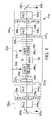
- FIG. 1is a schematic diagram of a preferred embodiment of a solid-state harmonic laser for providing two laser machining beams, employing an output port at each end of the laser resonator and employing extracavity wavelength converters.
- FIG. 2is a schematic diagram of a preferred embodiment of a solid-state harmonic laser for providing two laser machining beams, employing an output port at each end of the laser resonator and employing both intracavity and extracavity wavelength converters.
- FIG. 3is a schematic diagram of a preferred embodiment of a solid-state harmonic laser for providing two laser machining beams, employing an intracavity wavelength converter and an output port at each end of the laser resonator.
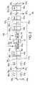
- FIG. 4is a schematic diagram of an alternative preferred embodiment of a solid-state harmonic laser for providing two laser machining beams, employing two laser media and multiple fold mirrors between the output ports.
- FIG. 5is a schematic diagram showing that two laser machining beams can be employed to machine separate targets.
- FIG. 6is a schematic diagram showing that two laser machining beams can be combined to machine the same target.
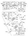
- FIG. 7is a schematic block diagram showing an embodiment of an exemplary laser system employing two laser pulse gating devices to provide on-demand, time-independent targeting for respective laser machining beams from the same resonator.
- FIG. 8is a schematic block diagram showing a generic embodiment of an exemplary laser employing at least one prism as an output port.
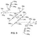
- FIG. 9is a schematic block diagram showing a specific embodiment of an exemplary laser employing two prisms as the output ports.
- FIG. 1is a schematic diagram of an embodiment of a laser 10 a including a laser resonator 20 a having two output ports 22 a , and 22 b , (generically, output ports 22 ) that are output-coupling resonator mirrors and are partly reflective to a fundamental infrared (IR) wavelength generated by one or more solid-state laser media 24 a 1 and 24 b 1 (generically, laser media 24 or laser medium 24 ) that are along an optical path 28 a within the laser resonator 20 a.
- IRfundamental infrared
- the laser media 24preferably comprise a conventional solid-state lasant such as Nd:YAG, Nd:YLF, Nd:YVO 4 , or Yb:YAG.
- laser media 24 a and 24 bwill comprise the same lasant, but skilled persons will appreciate that laser medium 24 a could be different from laser medium 24 b in composition, size, or dopant concentration, for example.
- Laser medium 24 bis shown in phantom lines because it can be omitted.
- the laser media 24are directly or indirectly pumped from the side by one or more diodes or diode arrays (not shown) that generate laser pumping light 30 a and 30 b (generically, pumping light 30 ), but skilled persons will appreciate that one or more intracavity fold mirrors or pumping input coupling mirrors 32 ( FIG. 4 ) and/or other well-known optical components (not shown) could be added to facilitate end-pumping. Skilled persons will appreciate that one or more lamps, lasers, or other pumping means could be employed to provide pumping light 30 .
- the laser resonator 20 aalso preferably, but not necessarily, includes a Q-switch 38 . If two laser media 24 are employed, the Q-switch 38 is preferably, but not necessarily, positioned between them along the optical path 28 a .
- One or more apertures 40 a and 40 bmay also be included in the laser resonator 20 a along the optical path 28 a . It is preferable to include one aperture 40 for each laser medium 24 , and it is preferable to position apertures 40 between respective laser media 24 and output ports 22 .
- wavelength converters 26 a 1 and 26 b 1can be positioned along the optical path 28 a outside of the laser resonator 20 a to convert the laser machining resonator outputs 27 a 1 and 27 b 1 (generically, resonator outputs 27 ) to harmonic laser machining beams 42 a 1 and 42 b 1 (generically, laser machining beams 42 ).
- the output ports 22 a 1 and 22 b 1are preferably about 5%–20% transmissive to the fundamental wavelength. If only one of the two wavelength converters 26 a 1 and 26 b 1 is employed, then one of the laser machining beams 42 will express the fundamental wavelength while the other laser machining beam 42 will express a harmonic wavelength.
- Each wavelength converter 26preferably comprises one or more nonlinear crystals 34 a and 34 b , such as 34 a 1 , 34 a 2 , 34 b 1 , and 34 b 2 (generically, nonlinear crystals 34 ) shown in FIG. 1 .
- the nonlinear crystals 34are also labeled with “NLC” in the figures.
- the nonlinear crystals 34 aare preferably generally identical to the respective nonlinear crystals 34 b .
- the nonlinear crystals 34 a 1 and 34 b 1preferably convert the resonator outputs 27 to second harmonic laser machining outputs 29 a and 29 b (generically, second harmonic wavelength outputs 29 ), and the nonlinear crystals 34 a 2 and 34 b 2 preferably convert second harmonic wavelength outputs 29 to the laser machining beams 42 , which in this embodiment preferably comprise the third harmonic wavelength. Skilled persons will appreciate, however, that the laser machining beams 42 could be adapted to comprise the fourth harmonic wavelength.
- Typical fundamental laser wavelengthsinclude, but are not limited to, 1,064 nm, which has harmonic wavelengths at 532 nm (frequency doubled), 355 nm (frequency tripled), 266 nm (frequency quadrupled), and 213 nm (frequency quintupled).
- different combinations of wavelength converters 26 on opposite sides of laser media 24could be employed to produce different harmonics of laser machining beam 42 on different sides of laser media 24 .
- the wavelength converters 26can be omitted from one or both sides of laser media 24 so that the one or both of the laser machining beams 42 may comprise the fundamental wavelength.
- harmonic laser machining beams 42 a and 42 bare desired to have substantially identical parameters, such as energy per pulse
- the components inside and outside of the laser resonator 20 ashould be arranged substantially symmetrically.
- one or more wave plates 36 a and/or 36 b (generically, wave plates 36 ) with or without polarizersare preferably added between the nonlinear crystals 34 of one or both sets of wavelength converters 26 to fine-tune the respective harmonic laser machining beams 42 a and 42 b to have one or more substantially identical parameters such as energy per pulse.
- the wave plate 36could be positioned between the output port 22 and the wavelength converter 26 .
- Other well-known energy control devicesincluding, but not limited to, a polarizer, an electro-optic device, an acousto-optic modulator or attenuator, a polarizer and a wave plate, or a polarizer and an electro-optic device, can additionally or alternatively be employed to control the energy of one or both laser machining beams 42 .
- laser machining beams 42are significantly different from low-energy reference beams, calibration beams, and dumped beams, some of which are often the result of inconsequential resonator leakage.
- the resonator componentscould be arranged in a variety of other combinations.
- the Q-switch 38 and the aperture 40could be positioned on the same side of the laser medium 24 .
- the cavity componentscan be configured to be substantially symmetrical in order to facilitate substantially similar harmonic laser machining beams 42 a and 42 b , or the cavity components can be configured to be intentionally asymmetrical in order to provide purposefully different harmonic laser machining beams 42 a and 42 b.
- the harmonic laser machining beams 42 a and 42 bare desired to have intentionally different parameters, such as wavelength, spot size, or energy per pulse, skilled persons can employ a wavelength converter 26 a that is different from the wavelength converter 26 b .
- the nonlinear crystals 34 acan have different dimensions, properties, or distinct number of crystals than the nonlinear crystals 34 b , or they may be spaced or configured differently inside or outside of the laser resonator 20 a .
- other resonator componentsmay be spaced differently on each side of the laser medium 24 so as to accommodate different beam powers and divergence angles.
- the wave plates 36 or other power control devicescan also be controlled to alter the parameters of either or both of the harmonic laser machining beams 42 a and 42 b , and the wave plate 36 a may also have different dimensions or properties than the wave plate 36 b in order to facilitate different respective harmonic laser machining beams 42 a and 42 b to suit different particular applications.
- the embodiment shownemploys reflective mirrors 48 a 1 and 48 b 1 (generically, mirrors 48 ) to direct the respective harmonic laser machining beams 42 a 1 and 42 b 1 to beam positioning and focusing system components (not shown).
- the mirrors 48are highly reflective to the wavelength of the harmonic laser machining beams 42 , such as the third harmonic, and are highly transmissive to the fundamental and other harmonic wavelengths, such as the second harmonic at a 45-degree angle.
- FIG. 2shows a preferred embodiment of a solid-state laser 10 b having both extracavity wavelength converters 26 a 2 and 26 b 2 and intracavity wavelength converters 26 c 2 and 26 d 2 and employing many of the same components of the solid-state laser 10 a in FIG. 1 .
- analogous components of the solid-state lasers 10 a and 10 bare generally labeled with analogous reference numerals in FIGS. 1-8 , although the lettering or subscripts may differ.
- a laser resonator 20 bincludes intracavity wavelength converters 26 c 2 and 26 d 2 that respectively preferably comprise one or more nonlinear crystals 34 a 1 and 34 b 1 . Because the laser resonator 20 b includes intracavity wavelength converters 26 C 2 and 26 d 2 , output ports 22 a 2 and 22 b 2 are preferably highly reflective to the fundamental wavelength generated by the laser medium 24 and are highly transmissive to a desired harmonic wavelength of the resonator outputs 27 a 2 and 27 b 2 .
- the resonator outputs 27comprise the second harmonic
- the extracavity wavelength converters 26 a 2 and 26 b 2 that respectively preferably comprise one or more nonlinear crystals 34 a 2 and 34 b 2preferably convert the resonator outputs 27 into the harmonic laser machining beams 42 a 2 and 42 b 2 , which preferably comprise the fourth harmonic wavelength.
- partly reflective mirrors 48 a 2 and 48 b 2are preferably highly reflective to the wavelength of the harmonic laser machining beams 42 , such as the fourth harmonic, and are highly transmissive to the second harmonic wavelengths at a 45-degree angle.
- Respective second sets of wave plates 36 a 2 and 36 b 2 , nonlinear crystals 34 a 2 and 34 b 2 , and partly reflective mirrors 48 a 2 and 48 b 2can be added to take advantage of the portions of the resonator (second harmonic) outputs 27 that propagate through the first set of partly reflective mirrors 48 , so that four beams of virtually identical or substantially different harmonic laser machining output can be provided.
- FIG. 3is a schematic diagram of a preferred embodiment of a laser 10 c including a laser resonator 20 c having two output ports 22 a 3 and 22 b 3 (generically, output ports 22 3 ) that are highly reflective to a fundamental wavelength generated by the laser medium 24 b 3 and are highly transmissive to a desired harmonic wavelength.
- the wavelength converters 26 e and 26 fare preferably positioned within the laser resonator 20 c toward the respective output ports 22 a 3 and 22 b 3 , and each wavelength converter 26 preferably comprises two or more nonlinear crystals 34 a , and 34 a 2 and 34 b 1 and 34 b 2 .
- wave plates 36 a 3 and 36 b 3with or without depolarizers, are added between the nonlinear crystals 34 of both wavelength converters 26 .
- a Q-switch 38 and/or an aperture 40may also be added, preferably between the wavelength converters 26 and on opposite sides of the laser medium 24 b 3 .
- the resonator componentscould be arranged in a variety of combinations to provide substantially similar or different harmonic laser machining beams 42 a 3 and 42 b 3 .
- the Q-switch 38 and the aperture 40can be positioned on the same side of the laser medium 24 b 3 , or the wave plates 36 3 can be omitted or be positioned on either side of both nonlinear crystals 34 of a given wavelength converter 26 .
- harmonic laser machining beams 42 a 3 and 42 b 3are desired to have the same parameters, then the symmetrical components are preferably identical; and if the harmonic laser machining beams 42 a 3 and 42 b 3 are desired to have intentionally different parameters, such as different wavelengths, then the symmetrical components, such as the wavelength converters 26 , may have different characteristics to provide desired differences in harmonic laser machining beams 42 .
- FIG. 4is a schematic diagram of a preferred embodiment of an alternative laser 10 d that also includes two sets of intracavity wavelength converters 26 e and 26 f , wave plates 36 a 3 and 36 b 3 , and output ports 22 a 3 and 22 b 3 .
- the laser resonator 20 dalso includes fold mirrors 32 a 1 , 32 a 2 , 32 b 1 , and 32 b 2 (generically, fold mirrors 32 , or 32 a , or 32 b ) and two distinct laser media 24 a 4 and 24 b 4 separated by the Q-switch 38 .
- the fold mirrors 32may be highly reflective to a fundamental wavelength generated by the laser media 24 and highly transmissive to a wavelength of the laser pumping light 30 a 1 , 30 a 2 , 30 b 1 , and 30 b 2 (generically, laser pumping light 30 , or 30 a , or 30 b ).
- the laser media 24are preferably substantially identical in size, composition, and orientation to the optical path 28 d
- the fold mirrors 32 a and 32 bare preferably substantially identical in size, shape, and angle of orientation to the optical path 28 d .
- the distances between these resonator components on either side of the laser media 24are also preferably symmetrical.
- resonator components and/or wavelength converters 26 on each side of the Q-switch 38may have different properties, different sequential or axial arrangement along the optical path 28 d , and/or different distances between them.
- the wave plates 36 or other energy control devicescan be controlled so that the pulse energy of pulses of the first laser machining beam 42 a is different from the pulse energy of pulses of the second laser machining beam 42 b.
- the harmonic laser machining beams 42can be manipulated in a variety of well-known beam-combining, beam-splitting, or beam-multiplexing techniques to perform well-known laser operations such as micromachining applications including, but not limited to, via drilling; semiconductor wafer slicing, dicing, or rounding; or other laser etching or scribing techniques.
- FIG. 5demonstrates embodiments of a laser system 50 a wherein the laser machining beams 42 a and 42 b from a solid-state laser 10 are directed by mirrors 48 a and 48 b along respective separate beam paths 52 a and 52 b and are directed by scan heads 56 a and 56 b at separate target locations on workpieces 54 a and 54 b supported by the same or different platforms 58 .
- Scan heads 56 a and 56 bare preferably part of a conventional beam positioning system ( FIG. 7 ), such as those described in detail, along with improvements, in U.S. Pat. No. 5,751,585 of Cutler et al., U.S. Pat. No. 6,430,465 of Cutler, or U.S. Pat. No. 4,532,402 of Overbeck, which are assigned to the assignee of this application and which are herein incorporated by reference.
- Other fixed-head or fast positioner-head systemssuch as galvanometer-, piezoelectrically-, or voice-coil-controlled mirrors, or linear motor-driven conventional positioning systems or those employed in the 5300 model series manufactured by Electro Scientific Industries, Inc. (ESI) of Portland, Oreg., could additionally or alternatively be employed.
- the workpieces 54 a and 54 bare substantially identical patterns, such as cell phone boards, and are preferably formed in similar alignments on a single printed circuit board (PCB) that is supported by the platform 58 , such as an X-Y table.
- PCBprinted circuit board
- Each workpiece 54 a and 54 bmay require substantially identical processing operations at the same or different locations.
- the workpieces 54 a and 54 bmay require several vias to be drilled at identical locations.
- a laser 10which provides two laser machining beams 42 a and 42 b for performing substantially identical processing operations on substantially identical workpieces 54 a and 54 b , offers several advantages over conventional laser systems that employ two distinct lasers or conventional systems that split a single beam from a single output laser. Many of the components and electronics that would be needed for two separate lasers are eliminated, so complexity and cost are reduced. The laser 10 also takes up less physical space and is more power-efficient than two separate lasers.
- each of the beams generated from the laser 10may have the same practical maximum output power as that of a single beam generated by a conventional laser, or, for example, the sum of the output powers from the first and second beams can be greater than the practical maximum output power of the traditional single-output beam.
- the two laser machining beams 42 a and 42 b generated by the laser 10are more likely to have identical pulse characteristics, especially when the resonator components are identical and are symmetrically positioned.
- Employing a laser 10 to provide the two laser machining beams 42 a and 42 bminimizes variations in age-related deterioration that would occur between different resonators, so the laser machining beams 42 a and 42 b are affected by substantially the same amount of cavity loss and/or performance drifting of the optical components or aging of the single or respective pumping source(s).
- Differences in beam characteristics from different resonatorscould result in one laser beam performing within acceptable tolerance while the other laser beam performs defective operations. For example, some vias may be drilled to a desirable depth or quality while other vias may be drilled in a manner that unacceptably damages the via bottom layer or surrounding layers.
- the acceptable range of laser pulse energiesis often referred to as a “process window.” For many laser processing applications, the process window requires that laser pulse energy vary by less than 5% from a selected pulse energy value.
- the laser machining beams 42 a and 42 bare, therefore, more likely to be performing substantially identical processing operations with substantially identical output parameters (varying by less than 5% of pulse energy, for example), especially at high repetition rates such as greater than 5 or 10 kHz at harmonic wavelengths, on substantially identical via patterns on the workpieces 54 a and 54 b , so that both of the laser machining beams 42 a and 42 b produce high-quality results, for example, making high-quality vias in PCBs.
- FIG. 6demonstrates embodiments of a laser system 50 b wherein the laser machining beams 42 a and 42 b from the laser 10 are combined through a beam combiner 60 to provide a single laser system output 42 e from the scan head 56 along the beam path 52 c .
- the beam combiner 60may include a fold mirror 48 c , a beam-combining mirror 62 , and an additional wave plate 36 c . If the beam paths 52 a and 52 b are substantially equal before they reach the beam combiner 60 , the laser system output 42 e has the combined energy per pulse of the laser machining beams 42 a and 42 b without affecting the shape of the laser pulse. Skilled persons will appreciate that the combined energy of the laser machining beams 42 a and 42 b may be as much as about twice the energy per pulse as that available from a conventional solid-state laser. Skilled persons will particularly appreciate these advantages when harmonic wavelengths are desired.
- an optional optical delay pathcan be employed along one of the beam paths 52 a or 52 b upstream of the beam combiner 60 to temporally separate the laser machining beams 42 a and 42 b in order to effectively elongate the pulse width experienced by a target or to provide immediately sequential pulses along the same beam path 52 c .
- the delay between the laser machining beams 42 a and 42 bwould preferably be from zero to about one pulse width, and the preferred combined adjustable pulse width would be from one to about two pulse widths of a given laser machining beam 42 .
- the delaycould be used to effectively double the repetition rate over the capabilities of a conventional single-output resonator.
- a small delay between the laser machining beams 42 a and 42 bcan also be accomplished by moving the beam combiner 60 to be at respectively smaller and larger distances from the final fold mirrors 48 a and 48 b in order to provide a slightly adjustable combined pulse width.
- the laser machining beams 42 a and 42 bcan be delivered sequentially or substantially simultaneously with a predetermined angular or lateral offset, such that the resulting laser spots are substantially adjacent to or substantially overlap one another. Skilled persons will also appreciate that these laser machining beams 42 a and 42 b can have the same parameters or have different wavelengths, pulse energies, or other beam characteristics.
- FIG. 7shows, as an example, a via-drilling system 110 that employs laser pulse gating devices 112 a and 112 b , positioned along beam paths 52 a and 52 b between the laser 10 and the respective scan heads 56 a and 56 b .
- a system controller or system computer 114controls the scan head 56 a to be aligned to a target location and then the directly or indirectly sends a “gating ON” gating control signal 116 a to the laser gating device 112 a , thereby prompting laser gating device 112 a to assume an output transmitting state.
- the output transmitting statepermits laser pulses of the laser machining beam 42 a to propagate through the first gating device 112 a and to be directed by the scan head 56 a in order to reach the target location and perform the desired laser processing operation.
- the system computer 114After a desired number of laser pulses of laser machining beam 42 a impinge the target location, the system computer 114 directly or indirectly shuts off the gating signal 116 a so that the gating device 112 a assumes a nontransmitting state and the laser machining beam 42 a is blocked from reaching the target location such as by being diverted to an absorber 118 a . Then the system computer 114 commands the first scan head 56 a to move and direct its aim at another target location before the system computer 114 sends another “gating ON” gating signal 116 a to the laser pulse gating device 112 a . The system computer 114 concurrently commands the second scan head 56 b and second gating device 112 b in the same manner, performing laser processing only when desired at the target locations swept by the second scan head 56 b.
- the laser 10can remain running at a predetermined repetition rate, so there is no thermal loading variation on the wavelength converter(s) 26 , and the thermally induced harmonic pulse energy drifting is thus eliminated.
- the laser machining beams 42 a and 42 bcan be gated completely independently of each other.
- scan heads 56 a and 56 bcan perform completely independent laser processing tasks at different locations on different materials concurrently as well as sequentially.
- the laser pulse gating devices 112 a and 112 bcan perform laser energy control functions as well, thereby enhancing the system's performance and reducing its cost.
- Exemplary laser pulse gating devicesinclude high speed electro-optic (E- 0 ) devices or acousto-optic (A-O) devices, such as Model N30085–05 made by NEOS Technologies, Melbourne, Fla. or modified versions of it. Further details concerning on-demand triggering of a laser pulse gating device 112 can be found in U.S. Pat. No. 6,172,325 of Baird et al. and U.S. patent application Ser. No. 10/611,798 of Sun et al., which are herein incorporated by reference.
- Radio-frequency (RF) loading control techniques described in U.S. patent application Ser. No. 10/611,798 of Sun et al.can additionally be employed to provide nearly constant thermal loading on an A-O laser pulse gating device 112 by applying an RF pulse to the A-O gating device 112 in coincidence with pulses of the laser machining beam 42 when the scan head 56 is over a target location (in other words, when a working laser machining beam 42 is demanded) and by applying an RF pulse with the same RF energy to the A-O gating device 112 but in noncoincidence with the pulses of the laser machining beam 42 when the scan head 56 is over an intermediate location (in other words, when a working laser machining beam 42 is not demanded).
- Skilled personswill appreciate that with such substantially constant thermal loading on an A-O gating device 112 , there are minimal adverse effects by an A-O gating device 112 on the quality and positioning accuracy of the working laser machining beam 42 .
- the RF power of the RF pulse on an A-O gating device 112can be adjusted to control the energy of the working laser machining beam 42 to meet target processing needs, while the RF duration of the RF pulse can be controlled accordingly to maintain a substantially constant RF energy or arithmetic product of the RF power and the RF duration of the RF pulse.
- FIG. 8shows an embodiment of an exemplary laser 10 d with components similar to those of the other lasers 10 , but specifically employing at least one prism 22 a 8 as at least one of its output ports 22 and employing a nontransmissive resonator mirror 32 a 8 at one end of resonator 20 d .
- Prism 22 b 8is shown in phantom because it may be included to serve as an output port 22 or may be omitted, or prism 22 b 8 may be employed as an output port 22 for one selected wavelength while output port 22 b 7 may be transmissive to the same or different wavelength in order to produce laser machining beams 42 b 8 and 42 b 7 .
- the wavelength converters 26 a and 26 bare shown in phantom and in alternative positions to emphasize variations described with respect to other embodiments. Their inclusion and positions may be varied. Similarly, laser medium 24 b is shown in phantom.
- FIG. 9shows a specific embodiment of an exemplary laser 10 e employing two prisms 22 a 8 and 22 b 8 as the output ports 22 .
- Laser 10 ealso includes end-pumped laser media 24 ; resonator end mirrors 32 a 8 and 32 b 8 ; and NLCs 34 a and 34 b , which are positioned between the resonator end mirrors 32 a 8 and 32 b 8 and the prisms 22 a 8 and 22 b 8 , respectively.
Landscapes
- Physics & Mathematics (AREA)
- Electromagnetism (AREA)
- Engineering & Computer Science (AREA)
- Plasma & Fusion (AREA)
- Optics & Photonics (AREA)
- Nonlinear Science (AREA)
- Lasers (AREA)
- Optical Modulation, Optical Deflection, Nonlinear Optics, Optical Demodulation, Optical Logic Elements (AREA)
Abstract
Description
Claims (64)
Priority Applications (9)
| Application Number | Priority Date | Filing Date | Title |
|---|---|---|---|
| US10/893,148US7139294B2 (en) | 2004-05-14 | 2004-07-16 | Multi-output harmonic laser and methods employing same |
| PCT/US2005/010196WO2005114801A1 (en) | 2004-05-14 | 2005-03-25 | Multi-output harmonic laser and methods employing same |
| CN2005800154653ACN1977429B (en) | 2004-05-14 | 2005-03-25 | Multi-output harmonic laser and methods employing same |
| GB0621383AGB2429578B (en) | 2004-05-14 | 2005-03-25 | Multi-output harmonic laser and methods employing same |
| DE112005001087TDE112005001087T5 (en) | 2004-05-14 | 2005-03-25 | Multi-output harmonic lasers and methods using same |
| JP2007513134AJP2008504671A (en) | 2004-05-14 | 2005-03-25 | Multi-output harmonic laser and method of using the same |
| KR1020067023635AKR20070012466A (en) | 2004-05-14 | 2005-03-25 | Multi-Power Harmonic Lasers and Methods of Using Such Lasers |
| TW094111629ATWI374593B (en) | 2004-05-14 | 2005-04-13 | Multi-output harmonic laser and methods employing same |
| US11/603,969US20070153841A1 (en) | 2004-05-14 | 2006-11-21 | Multi-output harmonic laser and methods employing same |
Applications Claiming Priority (2)
| Application Number | Priority Date | Filing Date | Title |
|---|---|---|---|
| US57144304P | 2004-05-14 | 2004-05-14 | |
| US10/893,148US7139294B2 (en) | 2004-05-14 | 2004-07-16 | Multi-output harmonic laser and methods employing same |
Related Child Applications (1)
| Application Number | Title | Priority Date | Filing Date |
|---|---|---|---|
| US11/603,969ContinuationUS20070153841A1 (en) | 2004-05-14 | 2006-11-21 | Multi-output harmonic laser and methods employing same |
Publications (2)
| Publication Number | Publication Date |
|---|---|
| US20050254530A1 US20050254530A1 (en) | 2005-11-17 |
| US7139294B2true US7139294B2 (en) | 2006-11-21 |
Family
ID=34964261
Family Applications (2)
| Application Number | Title | Priority Date | Filing Date |
|---|---|---|---|
| US10/893,148Expired - Fee RelatedUS7139294B2 (en) | 2004-05-14 | 2004-07-16 | Multi-output harmonic laser and methods employing same |
| US11/603,969AbandonedUS20070153841A1 (en) | 2004-05-14 | 2006-11-21 | Multi-output harmonic laser and methods employing same |
Family Applications After (1)
| Application Number | Title | Priority Date | Filing Date |
|---|---|---|---|
| US11/603,969AbandonedUS20070153841A1 (en) | 2004-05-14 | 2006-11-21 | Multi-output harmonic laser and methods employing same |
Country Status (8)
| Country | Link |
|---|---|
| US (2) | US7139294B2 (en) |
| JP (1) | JP2008504671A (en) |
| KR (1) | KR20070012466A (en) |
| CN (1) | CN1977429B (en) |
| DE (1) | DE112005001087T5 (en) |
| GB (1) | GB2429578B (en) |
| TW (1) | TWI374593B (en) |
| WO (1) | WO2005114801A1 (en) |
Cited By (2)
| Publication number | Priority date | Publication date | Assignee | Title |
|---|---|---|---|---|
| US20140092925A1 (en)* | 2006-01-20 | 2014-04-03 | John Redvers Clowes | Optical pulse apparatus and method |
| US11440136B2 (en)* | 2017-03-07 | 2022-09-13 | Robert Bosch Gmbh | Method and device for shaping radiation for laser processing |
Families Citing this family (17)
| Publication number | Priority date | Publication date | Assignee | Title |
|---|---|---|---|---|
| US6947454B2 (en)* | 2003-06-30 | 2005-09-20 | Electro Scientific Industries, Inc. | Laser pulse picking employing controlled AOM loading |
| US20060114948A1 (en)* | 2004-11-29 | 2006-06-01 | Lo Ho W | Workpiece processing system using a common imaged optical assembly to shape the spatial distributions of light energy of multiple laser beams |
| US7289549B2 (en)* | 2004-12-09 | 2007-10-30 | Electro Scientific Industries, Inc. | Lasers for synchronized pulse shape tailoring |
| US20060128073A1 (en)* | 2004-12-09 | 2006-06-15 | Yunlong Sun | Multiple-wavelength laser micromachining of semiconductor devices |
| US20070286247A1 (en)* | 2006-06-12 | 2007-12-13 | Pang H Yang | Frequency-doubled laser resonator including two optically nonlinear crystals |
| US7727796B2 (en)* | 2007-04-26 | 2010-06-01 | Oxford Instruments Analytical Oy | Method for patterning detector crystal using Q-switched laser |
| US8116341B2 (en)* | 2007-05-31 | 2012-02-14 | Electro Scientific Industries, Inc. | Multiple laser wavelength and pulse width process drilling |
| US7817686B2 (en)* | 2008-03-27 | 2010-10-19 | Electro Scientific Industries, Inc. | Laser micromachining using programmable pulse shapes |
| WO2009137182A2 (en) | 2008-03-31 | 2009-11-12 | Electro Scientific Industries, Inc. | Combining multiple laser beams to form high repetition rate, high average power polarized laser beam |
| KR101016175B1 (en) | 2010-12-27 | 2011-02-24 | 광주과학기술원 | Parallel hybrid multiband mid-infrared fiber laser generator |
| KR101109430B1 (en) | 2011-01-19 | 2012-01-31 | 광주과학기술원 | Parallel hybrid multiband mid-infrared fiber laser generator |
| CN104701724A (en)* | 2015-03-20 | 2015-06-10 | 中国科学技术大学 | Dual optical path device for connecting pulse laser with terminal experiment cavity |
| KR101632075B1 (en)* | 2016-03-21 | 2016-06-20 | 주식회사 제이티에스인더스트리 | ND-YAG laser system For skin treatment using Stable resonator and Unstable resonator |
| CN106238905B (en)* | 2016-06-14 | 2019-06-21 | 昆山国显光电有限公司 | A kind of laser energy automatic compensating method and equipment |
| JP2017221969A (en)* | 2016-06-17 | 2017-12-21 | 株式会社ブイ・テクノロジー | Laser lift-off device |
| TWI699251B (en)* | 2018-11-22 | 2020-07-21 | 財團法人工業技術研究院 | Laser machining device |
| CN114682908A (en)* | 2020-12-31 | 2022-07-01 | 苏州创鑫激光科技有限公司 | Laser output system, processing platform and output method |
Citations (31)
| Publication number | Priority date | Publication date | Assignee | Title |
|---|---|---|---|---|
| US3947780A (en) | 1974-10-21 | 1976-03-30 | Mcdonnell Douglas Corporation | Acoustooptic mode-locker frequency doubler |
| US5231641A (en) | 1992-01-21 | 1993-07-27 | Laserscope | Crystalline slab laser with intracavity non-linear optic |
| US5272309A (en) | 1990-08-01 | 1993-12-21 | Microelectronics And Computer Technology Corporation | Bonding metal members with multiple laser beams |
| US5361268A (en) | 1993-05-18 | 1994-11-01 | Electro Scientific Industries, Inc. | Switchable two-wavelength frequency-converting laser system and power control therefor |
| US5586138A (en) | 1994-04-26 | 1996-12-17 | Nec Corporation | Multiple-cavity semiconductor laser capable of generating ultrashort light pulse train with ultrahigh repetition rate |
| WO1998001790A1 (en) | 1996-07-04 | 1998-01-15 | The Secretary Of State For Defence | An optical harmonic generator |
| WO1998052260A1 (en) | 1997-05-16 | 1998-11-19 | Excel Quantronix Corp. | Intra-cavity and inter-cavity harmonics generation in high power lasers |
| US5841099A (en) | 1994-07-18 | 1998-11-24 | Electro Scientific Industries, Inc. | Method employing UV laser pulses of varied energy density to form depthwise self-limiting blind vias in multilayered targets |
| US5847960A (en) | 1995-03-20 | 1998-12-08 | Electro Scientific Industries, Inc. | Multi-tool positioning system |
| US5850407A (en) | 1997-11-25 | 1998-12-15 | Lightwave Electronics Corporation | Third-harmonic generator with uncoated brewster-cut dispersive output facet |
| EP0884128A1 (en) | 1996-11-20 | 1998-12-16 | Ibiden Co., Ltd. | Laser machining apparatus, and apparatus and method for manufacturing a multilayered printed wiring board |
| US5854870A (en) | 1990-05-25 | 1998-12-29 | Hitachi, Ltd. | Short-wavelength laser light source |
| JPH1190659A (en) | 1997-09-22 | 1999-04-06 | Nikon Corp | Laser repair device |
| US6097742A (en) | 1999-03-05 | 2000-08-01 | Coherent, Inc. | High-power external-cavity optically-pumped semiconductor lasers |
| US6169014B1 (en) | 1998-09-04 | 2001-01-02 | U.S. Philips Corporation | Laser crystallization of thin films |
| WO2001014096A1 (en) | 1999-08-20 | 2001-03-01 | Electro Scientific Industries, Inc. | Multiple ultraviolet beam solid-state laser systems and methods |
| US6210401B1 (en) | 1991-08-02 | 2001-04-03 | Shui T. Lai | Method of, and apparatus for, surgery of the cornea |
| US6252195B1 (en) | 1999-04-26 | 2001-06-26 | Ethicon, Inc. | Method of forming blind holes in surgical needles using a diode pumped Nd-YAG laser |
| US6281471B1 (en) | 1999-12-28 | 2001-08-28 | Gsi Lumonics, Inc. | Energy-efficient, laser-based method and system for processing target material |
| US20010021205A1 (en) | 1999-12-04 | 2001-09-13 | Olaf Kittelmann | Q-switched solid state laser with adjustable pulse length |
| US6292504B1 (en) | 1999-03-16 | 2001-09-18 | Raytheon Company | Dual cavity laser resonator |
| US6339604B1 (en) | 1998-06-12 | 2002-01-15 | General Scanning, Inc. | Pulse control in laser systems |
| US6356575B1 (en) | 1999-07-06 | 2002-03-12 | Raytheon Company | Dual cavity multifunction laser system |
| US6541731B2 (en) | 2000-01-25 | 2003-04-01 | Aculight Corporation | Use of multiple laser sources for rapid, flexible machining and production of vias in multi-layered substrates |
| US6574250B2 (en) | 2000-01-10 | 2003-06-03 | Electro Scientific Industries, Inc. | Laser system and method for processing a memory link with a burst of laser pulses having ultrashort pulse widths |
| US6697394B2 (en) | 2000-02-10 | 2004-02-24 | Jenoptik Ldt Gmbh | Directly modulatable laser |
| US6703582B2 (en) | 1999-12-28 | 2004-03-09 | Gsi Lumonics Corporation | Energy-efficient method and system for processing target material using an amplified, wavelength-shifted pulse train |
| US20040134896A1 (en) | 1999-12-28 | 2004-07-15 | Bo Gu | Laser-based method and system for memory link processing with picosecond lasers |
| US20040134894A1 (en) | 1999-12-28 | 2004-07-15 | Bo Gu | Laser-based system for memory link processing with picosecond lasers |
| US6878899B2 (en) | 1996-12-24 | 2005-04-12 | Gsi Lumonics Corp. | Laser processing |
| US20050117620A1 (en) | 2002-03-28 | 2005-06-02 | Pierre-Yves Thro | High peak power laser cavity and assembly of several such cavities |
Family Cites Families (8)
| Publication number | Priority date | Publication date | Assignee | Title |
|---|---|---|---|---|
| JPS5124192A (en)* | 1974-08-02 | 1976-02-26 | Hitachi Ltd | KOHIIRENTOKOGENSOCHI |
| JPH03117861U (en)* | 1990-03-19 | 1991-12-05 | ||
| JP3213882B2 (en)* | 1997-03-21 | 2001-10-02 | 住友重機械工業株式会社 | Laser processing apparatus and processing method |
| KR100446052B1 (en)* | 1997-05-15 | 2004-10-14 | 스미도모쥬기가이고교 가부시키가이샤 | Laser beam machining apparatus using a plurality of galvanoscanners |
| JP2000216465A (en)* | 1999-01-21 | 2000-08-04 | Mitsubishi Electric Corp | Laser resonator |
| JP2002246677A (en)* | 2001-02-14 | 2002-08-30 | Toshiba Corp | Laser oscillator and laser processing equipment |
| JP2002314180A (en)* | 2001-04-13 | 2002-10-25 | Toshiba Corp | Laser oscillator and oscillation method |
| JP2003094191A (en)* | 2001-09-20 | 2003-04-02 | Yaskawa Electric Corp | Laser processing equipment |
- 2004
- 2004-07-16USUS10/893,148patent/US7139294B2/ennot_activeExpired - Fee Related
- 2005
- 2005-03-25CNCN2005800154653Apatent/CN1977429B/ennot_activeExpired - Fee Related
- 2005-03-25WOPCT/US2005/010196patent/WO2005114801A1/enactiveApplication Filing
- 2005-03-25KRKR1020067023635Apatent/KR20070012466A/ennot_activeCeased
- 2005-03-25GBGB0621383Apatent/GB2429578B/ennot_activeExpired - Fee Related
- 2005-03-25DEDE112005001087Tpatent/DE112005001087T5/ennot_activeWithdrawn
- 2005-03-25JPJP2007513134Apatent/JP2008504671A/enactivePending
- 2005-04-13TWTW094111629Apatent/TWI374593B/ennot_activeIP Right Cessation
- 2006
- 2006-11-21USUS11/603,969patent/US20070153841A1/ennot_activeAbandoned
Patent Citations (39)
| Publication number | Priority date | Publication date | Assignee | Title |
|---|---|---|---|---|
| US3947780A (en) | 1974-10-21 | 1976-03-30 | Mcdonnell Douglas Corporation | Acoustooptic mode-locker frequency doubler |
| US5854870A (en) | 1990-05-25 | 1998-12-29 | Hitachi, Ltd. | Short-wavelength laser light source |
| US5272309A (en) | 1990-08-01 | 1993-12-21 | Microelectronics And Computer Technology Corporation | Bonding metal members with multiple laser beams |
| US6210401B1 (en) | 1991-08-02 | 2001-04-03 | Shui T. Lai | Method of, and apparatus for, surgery of the cornea |
| US5231641A (en) | 1992-01-21 | 1993-07-27 | Laserscope | Crystalline slab laser with intracavity non-linear optic |
| US5361268A (en) | 1993-05-18 | 1994-11-01 | Electro Scientific Industries, Inc. | Switchable two-wavelength frequency-converting laser system and power control therefor |
| US5586138A (en) | 1994-04-26 | 1996-12-17 | Nec Corporation | Multiple-cavity semiconductor laser capable of generating ultrashort light pulse train with ultrahigh repetition rate |
| US5841099A (en) | 1994-07-18 | 1998-11-24 | Electro Scientific Industries, Inc. | Method employing UV laser pulses of varied energy density to form depthwise self-limiting blind vias in multilayered targets |
| US5847960A (en) | 1995-03-20 | 1998-12-08 | Electro Scientific Industries, Inc. | Multi-tool positioning system |
| WO1998001790A1 (en) | 1996-07-04 | 1998-01-15 | The Secretary Of State For Defence | An optical harmonic generator |
| EP0884128A1 (en) | 1996-11-20 | 1998-12-16 | Ibiden Co., Ltd. | Laser machining apparatus, and apparatus and method for manufacturing a multilayered printed wiring board |
| US6878899B2 (en) | 1996-12-24 | 2005-04-12 | Gsi Lumonics Corp. | Laser processing |
| US5943351A (en) | 1997-05-16 | 1999-08-24 | Excel/Quantronix, Inc. | Intra-cavity and inter-cavity harmonics generation in high-power lasers |
| WO1998052260A1 (en) | 1997-05-16 | 1998-11-19 | Excel Quantronix Corp. | Intra-cavity and inter-cavity harmonics generation in high power lasers |
| JPH1190659A (en) | 1997-09-22 | 1999-04-06 | Nikon Corp | Laser repair device |
| US5850407A (en) | 1997-11-25 | 1998-12-15 | Lightwave Electronics Corporation | Third-harmonic generator with uncoated brewster-cut dispersive output facet |
| US6339604B1 (en) | 1998-06-12 | 2002-01-15 | General Scanning, Inc. | Pulse control in laser systems |
| US6169014B1 (en) | 1998-09-04 | 2001-01-02 | U.S. Philips Corporation | Laser crystallization of thin films |
| US6097742A (en) | 1999-03-05 | 2000-08-01 | Coherent, Inc. | High-power external-cavity optically-pumped semiconductor lasers |
| US6292504B1 (en) | 1999-03-16 | 2001-09-18 | Raytheon Company | Dual cavity laser resonator |
| US6252195B1 (en) | 1999-04-26 | 2001-06-26 | Ethicon, Inc. | Method of forming blind holes in surgical needles using a diode pumped Nd-YAG laser |
| US6356575B1 (en) | 1999-07-06 | 2002-03-12 | Raytheon Company | Dual cavity multifunction laser system |
| WO2001014096A1 (en) | 1999-08-20 | 2001-03-01 | Electro Scientific Industries, Inc. | Multiple ultraviolet beam solid-state laser systems and methods |
| US20010021205A1 (en) | 1999-12-04 | 2001-09-13 | Olaf Kittelmann | Q-switched solid state laser with adjustable pulse length |
| US20050092720A1 (en) | 1999-12-28 | 2005-05-05 | Gsi Lumonics Corporation | Laser-based method and system for memory link processing with picosecond lasers |
| US20040188399A1 (en) | 1999-12-28 | 2004-09-30 | Gsi Lumonics Inc. | Energy-efficient, laser-based method and system for processing target material |
| US20050150880A1 (en) | 1999-12-28 | 2005-07-14 | Gsi Lumonics Corporation | Laser-based method and system for memory link processing with picosecond lasers |
| US6703582B2 (en) | 1999-12-28 | 2004-03-09 | Gsi Lumonics Corporation | Energy-efficient method and system for processing target material using an amplified, wavelength-shifted pulse train |
| US6727458B2 (en) | 1999-12-28 | 2004-04-27 | Gsi Lumonics, Inc. | Energy-efficient, laser-based method and system for processing target material |
| US20040134896A1 (en) | 1999-12-28 | 2004-07-15 | Bo Gu | Laser-based method and system for memory link processing with picosecond lasers |
| US20040134894A1 (en) | 1999-12-28 | 2004-07-15 | Bo Gu | Laser-based system for memory link processing with picosecond lasers |
| US20050150879A1 (en) | 1999-12-28 | 2005-07-14 | Gsi Lumonics Corporation | Laser-based method and system for memory link processing with picosecond lasers |
| US20050115936A1 (en) | 1999-12-28 | 2005-06-02 | Gsi Lumonics Corporation | Laser-based method and system for memory link processing with picosecond lasers |
| US6281471B1 (en) | 1999-12-28 | 2001-08-28 | Gsi Lumonics, Inc. | Energy-efficient, laser-based method and system for processing target material |
| US20050115937A1 (en) | 1999-12-28 | 2005-06-02 | Gsi Lumonics Corporation | Laser-based method and system for memory link processing with picosecond lasers |
| US6574250B2 (en) | 2000-01-10 | 2003-06-03 | Electro Scientific Industries, Inc. | Laser system and method for processing a memory link with a burst of laser pulses having ultrashort pulse widths |
| US6541731B2 (en) | 2000-01-25 | 2003-04-01 | Aculight Corporation | Use of multiple laser sources for rapid, flexible machining and production of vias in multi-layered substrates |
| US6697394B2 (en) | 2000-02-10 | 2004-02-24 | Jenoptik Ldt Gmbh | Directly modulatable laser |
| US20050117620A1 (en) | 2002-03-28 | 2005-06-02 | Pierre-Yves Thro | High peak power laser cavity and assembly of several such cavities |
Non-Patent Citations (1)
| Title |
|---|
| Aug. 8, 2005 International Search Report and the Written Opinion concerning the corresponding PCT/US2005/010196. |
Cited By (3)
| Publication number | Priority date | Publication date | Assignee | Title |
|---|---|---|---|---|
| US20140092925A1 (en)* | 2006-01-20 | 2014-04-03 | John Redvers Clowes | Optical pulse apparatus and method |
| US8767287B2 (en)* | 2006-01-20 | 2014-07-01 | Fianium Ltd. | Optical pulse apparatus and method |
| US11440136B2 (en)* | 2017-03-07 | 2022-09-13 | Robert Bosch Gmbh | Method and device for shaping radiation for laser processing |
Also Published As
| Publication number | Publication date |
|---|---|
| CN1977429A (en) | 2007-06-06 |
| GB0621383D0 (en) | 2006-12-06 |
| WO2005114801A1 (en) | 2005-12-01 |
| TW200537775A (en) | 2005-11-16 |
| GB2429578B (en) | 2008-09-17 |
| JP2008504671A (en) | 2008-02-14 |
| DE112005001087T5 (en) | 2007-04-19 |
| US20050254530A1 (en) | 2005-11-17 |
| KR20070012466A (en) | 2007-01-25 |
| GB2429578A (en) | 2007-02-28 |
| TWI374593B (en) | 2012-10-11 |
| CN1977429B (en) | 2012-02-01 |
| WO2005114801A8 (en) | 2006-02-02 |
| US20070153841A1 (en) | 2007-07-05 |
Similar Documents
| Publication | Publication Date | Title |
|---|---|---|
| US20070153841A1 (en) | Multi-output harmonic laser and methods employing same | |
| US6947454B2 (en) | Laser pulse picking employing controlled AOM loading | |
| US8081668B2 (en) | High energy pulse suppression method | |
| US8374206B2 (en) | Combining multiple laser beams to form high repetition rate, high average power polarized laser beam | |
| US6784399B2 (en) | Micromachining with high-energy, intra-cavity Q-switched CO2 laser pulses | |
| US7301981B2 (en) | Methods for synchronized pulse shape tailoring | |
| US7420995B2 (en) | Simultaneously mode-locked, Q-switched laser | |
| KR20100135772A (en) | Multi-Pass Optical Power Amplifier | |
| KR20090037895A (en) | Series photon amplifier | |
| EP3338328B1 (en) | Method of laser-machining a workpiece with a carbon monoxide laser | |
| KR20150138050A (en) | External Diffusion Amplifier | |
| US9414498B2 (en) | Via-hole drilling in a printed circuit board using a carbon monoxide laser | |
| JP2005313195A (en) | Double wavelength superposing type laser beam emission unit, and laser beam machining apparatus | |
| US7006283B2 (en) | Three-dimensional optical amplifier structure | |
| US20100193481A1 (en) | Laser constructed with multiple output couplers to generate multiple output beams | |
| US20030142703A1 (en) | Third harmonic laser system | |
| EP0792530A1 (en) | Low cost, high average power, high brightness solid state laser | |
| KR102252412B1 (en) | Laser apparatus for treatment of skin which can adjust the duration of pulse and change the wavelength easily | |
| WO2006062744A2 (en) | Methods and systems for synchronized pulse shape tailoring | |
| KR20070085548A (en) | Efficient micro-machining apparatus and method using multiple laser beams | |
| US20190334309A1 (en) | Method and apparatus for repetition rate synchronisation of mode-locked lasers | |
| JP2004358486A (en) | Laser beam machining method using mode lock laser | |
| Dunsky et al. | Precision microfabrication with Q-switched CO2 lasers | |
| Li et al. | Quasi-white-light generation in optical superlattice using all-solid-state laser technique |
Legal Events
| Date | Code | Title | Description |
|---|---|---|---|
| AS | Assignment | Owner name:ELECTRO SCIENTIFIC INDUSTRIES, INC., OREGON Free format text:ASSIGNMENT OF ASSIGNORS INTEREST;ASSIGNOR:SUN, YUNLONG;REEL/FRAME:015795/0518 Effective date:20040823 Owner name:ELECTRO SCIENTIFIC INDUSTRIES, INC., OREGON Free format text:ASSIGNMENT OF ASSIGNORS INTEREST;ASSIGNOR:SUN, YUNLONG;REEL/FRAME:015809/0898 Effective date:20040823 | |
| FPAY | Fee payment | Year of fee payment:4 | |
| FPAY | Fee payment | Year of fee payment:8 | |
| FEPP | Fee payment procedure | Free format text:MAINTENANCE FEE REMINDER MAILED (ORIGINAL EVENT CODE: REM.) | |
| LAPS | Lapse for failure to pay maintenance fees | Free format text:PATENT EXPIRED FOR FAILURE TO PAY MAINTENANCE FEES (ORIGINAL EVENT CODE: EXP.); ENTITY STATUS OF PATENT OWNER: LARGE ENTITY | |
| STCH | Information on status: patent discontinuation | Free format text:PATENT EXPIRED DUE TO NONPAYMENT OF MAINTENANCE FEES UNDER 37 CFR 1.362 | |
| FP | Lapsed due to failure to pay maintenance fee | Effective date:20181121 | |
| AS | Assignment | Owner name:BARCLAYS BANK PLC, AS COLLATERAL AGENT, NEW YORK Free format text:PATENT SECURITY AGREEMENT (ABL);ASSIGNORS:ELECTRO SCIENTIFIC INDUSTRIES, INC.;MKS INSTRUMENTS, INC.;NEWPORT CORPORATION;REEL/FRAME:048211/0312 Effective date:20190201 Owner name:BARCLAYS BANK PLC, AS COLLATERAL AGENT, NEW YORK Free format text:PATENT SECURITY AGREEMENT (TERM LOAN);ASSIGNORS:ELECTRO SCIENTIFIC INDUSTRIES, INC.;MKS INSTRUMENTS, INC.;NEWPORT CORPORATION;REEL/FRAME:048211/0227 Effective date:20190201 | |
| AS | Assignment | Owner name:BARCLAYS BANK PLC, AS COLLATERAL AGENT, NEW YORK Free format text:CORRECTIVE ASSIGNMENT TO CORRECT THE REMOVE U.S. PATENT NO. 7,919,646 PREVIOUSLY RECORDED ON REEL 048211 FRAME 0227. ASSIGNOR(S) HEREBY CONFIRMS THE PATENT SECURITY AGREEMENT (TERM LOAN);ASSIGNORS:ELECTRO SCIENTIFIC INDUSTRIES, INC.;MKS INSTRUMENTS, INC.;NEWPORT CORPORATION;REEL/FRAME:055006/0492 Effective date:20190201 Owner name:BARCLAYS BANK PLC, AS COLLATERAL AGENT, NEW YORK Free format text:CORRECTIVE ASSIGNMENT TO CORRECT THE REMOVE U.S. PATENT NO.7,919,646 PREVIOUSLY RECORDED ON REEL 048211 FRAME 0312. ASSIGNOR(S) HEREBY CONFIRMS THE PATENT SECURITY AGREEMENT (ABL);ASSIGNORS:ELECTRO SCIENTIFIC INDUSTRIES, INC.;MKS INSTRUMENTS, INC.;NEWPORT CORPORATION;REEL/FRAME:055668/0687 Effective date:20190201 | |
| AS | Assignment | Owner name:ELECTRO SCIENTIFIC INDUSTRIES, INC., OREGON Free format text:RELEASE BY SECURED PARTY;ASSIGNOR:BARCLAYS BANK PLC;REEL/FRAME:063009/0001 Effective date:20220817 Owner name:NEWPORT CORPORATION, MASSACHUSETTS Free format text:RELEASE BY SECURED PARTY;ASSIGNOR:BARCLAYS BANK PLC;REEL/FRAME:063009/0001 Effective date:20220817 Owner name:MKS INSTRUMENTS, INC., MASSACHUSETTS Free format text:RELEASE BY SECURED PARTY;ASSIGNOR:BARCLAYS BANK PLC;REEL/FRAME:063009/0001 Effective date:20220817 Owner name:ELECTRO SCIENTIFIC INDUSTRIES, INC., OREGON Free format text:RELEASE BY SECURED PARTY;ASSIGNOR:BARCLAYS BANK PLC;REEL/FRAME:062739/0001 Effective date:20220817 Owner name:NEWPORT CORPORATION, MASSACHUSETTS Free format text:RELEASE BY SECURED PARTY;ASSIGNOR:BARCLAYS BANK PLC;REEL/FRAME:062739/0001 Effective date:20220817 Owner name:MKS INSTRUMENTS, INC., MASSACHUSETTS Free format text:RELEASE BY SECURED PARTY;ASSIGNOR:BARCLAYS BANK PLC;REEL/FRAME:062739/0001 Effective date:20220817 |