US7139116B1 - Post amplification optical isolator - Google Patents
Post amplification optical isolatorDownload PDFInfo
- Publication number
- US7139116B1 US7139116B1US11/333,824US33382406AUS7139116B1US 7139116 B1US7139116 B1US 7139116B1US 33382406 AUS33382406 AUS 33382406AUS 7139116 B1US7139116 B1US 7139116B1
- Authority
- US
- United States
- Prior art keywords
- pulse
- laser pulse
- optical isolator
- target material
- amplified
- Prior art date
- Legal status (The legal status is an assumption and is not a legal conclusion. Google has not performed a legal analysis and makes no representation as to the accuracy of the status listed.)
- Active
Links
Images


Classifications
- H—ELECTRICITY
- H01—ELECTRIC ELEMENTS
- H01S—DEVICES USING THE PROCESS OF LIGHT AMPLIFICATION BY STIMULATED EMISSION OF RADIATION [LASER] TO AMPLIFY OR GENERATE LIGHT; DEVICES USING STIMULATED EMISSION OF ELECTROMAGNETIC RADIATION IN WAVE RANGES OTHER THAN OPTICAL
- H01S3/00—Lasers, i.e. devices using stimulated emission of electromagnetic radiation in the infrared, visible or ultraviolet wave range
- H01S3/005—Optical devices external to the laser cavity, specially adapted for lasers, e.g. for homogenisation of the beam or for manipulating laser pulses, e.g. pulse shaping
- H01S3/0057—Temporal shaping, e.g. pulse compression, frequency chirping
- H—ELECTRICITY
- H01—ELECTRIC ELEMENTS
- H01S—DEVICES USING THE PROCESS OF LIGHT AMPLIFICATION BY STIMULATED EMISSION OF RADIATION [LASER] TO AMPLIFY OR GENERATE LIGHT; DEVICES USING STIMULATED EMISSION OF ELECTROMAGNETIC RADIATION IN WAVE RANGES OTHER THAN OPTICAL
- H01S3/00—Lasers, i.e. devices using stimulated emission of electromagnetic radiation in the infrared, visible or ultraviolet wave range
- H01S3/005—Optical devices external to the laser cavity, specially adapted for lasers, e.g. for homogenisation of the beam or for manipulating laser pulses, e.g. pulse shaping
- H01S3/0064—Anti-reflection devices, e.g. optical isolaters
Definitions
- the inventionis in the field of laser systems and specifically in the field of short laser pulse generation.
- Optical isolatorsare used in laser systems to assure that light travels in one direction but not another.
- an optical isolatorcan be used to assure that light travels in one direction around the ring rather than in both directions.
- Optical isolatorscan also be used to prevent light from traveling back along a beam path from an amplifier to sensitive components of a laser system.
- an Optical Isolator 100typically includes an Entrance Polarizer 110 , a Faraday Rotator 120 and an Exit Polarizer 130 .
- Light 140can pass from Entrance Polarizer 110 , through Faraday Rotator 120 and out through Exit Polarizer 130 , but is prevented from passing in the reverse direction, e.g., through Exit Polarizer 130 , Faraday Rotator 120 and then out through Entrance Polarizer 110 .
- Optical polarizers of the type illustrated in FIG. 1typically have transmission efficiencies in the range of 50 percent in the forward direction and 0.1 percent in the reverse direction.
- a CPA 200includes a Pulse Source 210 , a Pulse Expander 220 , an Optical Isolator 100 , a Pulse Amplifier 240 and a Pulse Compressor 250 .
- Optical Isolator 100is configured to prevent light, for example generated by spontaneous emission within Pulse Amplifier 240 , from traveling back to Pulse Source 210 .
- Light pulses generated using Pulse Amplifier 240 and Pulse Compressor 250are optionally directed at a Target Material 260 for the purposes of material modification, ablation, or the like.
- the systems of the prior arthave a number of disadvantages including, for example, the inefficiency of Optical Isolator 100 , the size of bulk optical components, and the sensitivity of Optical Isolator 100 to high peak power light and angular alignment. There is, therefore, a need for improved systems and methods in CPA systems.
- Various embodiments of the inventioninclude components configured at the same time to function as both a pulse compressor and an optical isolator. Both isolation and pulse compression are achieved by using a pulse compressor as a polarizer within an optical isolator.
- the pulse compressorcompresses a laser pulse while at the same time helping to assure that any light traveling in the reverse direction will have a polarization that will prevent it from passing completely through an optical isolator.
- one of the polarizers within the combination compressor/isolatorincludes a sub-wavelength polarizer with integrated magnetic materials.
- Various embodiments of the inventionfurther include an optical isolator disposed along a beam path between a final pulse amplifier and a target material.
- This optical isolatoris configured to prevent light generated at the target material, for example through Rayleigh scattering, from reaching the pulse amplifier, being amplified and possibly reaching other components of the system.
- Various embodiments of the inventioninclude a system comprising a first polarization unit of an optical isolator, a second polarization unit of the optical isolator, the second polarization unit being configured for modifying a temporal length of a laser pulse, and a Faraday rotator disposed between the first polarization unit and the second polarization unit.
- Various embodiments of the inventioninclude a method comprising receiving a laser pulse at a first polarization unit, modifying the polarization of the laser pulse using a Faraday rotator or a mode converter, receiving the laser pulse at a second polarization unit, and modifying a temporal length of the laser pulse using the first polarization unit or the second polarization unit, the first polarization unit and second polarization unit being configured to form an optical isolator.
- Various embodiments of the inventioninclude a system comprising means for receiving a laser pulse at a first polarization unit, the first polarization unit and a second polarization unit being configured to form an optical isolator, means for modifying the polarization of the laser pulse, the means for modifying the polarization of the laser pulse being included in the optical isolator, and means for temporally compressing or expanding the laser pulse using the second polarization unit.
- Various embodiments of the inventioninclude a system comprising a pulse source configured to provide a laser pulse, a pulse amplifier configured to amplify the laser pulse, a delivery device configured to deliver the amplified laser pulse to a target material, and an optical isolator configured to prevent light from the target material from reaching the pulse amplifier.
- the optical isolatoris optionally disposed between the target material and the delivery device, or between the delivery device and the pulse amplifier.
- the pulse amplifieris optionally a last pulse amplifier of a plurality of pulse amplifiers disposed along a beam line of the laser pulse.
- Various embodiments of the inventioninclude a system comprising a pulse source configured to provide a laser pulse, one or more pulse amplifiers configured to amplify the laser pulse to generate an amplified laser pulse, a delivery device configured to deliver the amplified laser pulse to a target material, and an optical isolator configured to prevent light from the target material from reaching any of the one or more pulse amplifiers.
- Various embodiments of the inventioninclude a system comprising a pulse source configured to provide a laser pulse, a pulse expander configured to expand the laser pulse provided by the pulse source to produce an expanded laser pulse, a pulse amplifier configured to amplify the expanded laser pulse to produce an amplified laser pulse, a pulse compressor configured to compress the amplified laser pulse to produce a compressed laser pulse, and an optical isolator configured to prevent light resulting from the compressed laser pulse from reaching the pulse amplifier.
- Various embodiments of the inventioninclude a method of modifying a target material, the method comprising generating a laser pulse using a pulse source, amplifying the laser pulse using one or more pulse amplifiers to generate an amplified laser pulse, delivering the amplified laser pulse to a target material, and using an optical isolator to prevent light resulting from the delivery of the amplified laser pulse to the target material from reaching any of the one or more pulse amplifiers.
- FIG. 1illustrates an optical isolator according to the prior art
- FIG. 2illustrates a chirped laser system according to the prior art
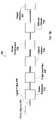
- FIG. 3illustrates a combination optical isolator and pulse compressor, according to various embodiments of the invention
- FIG. 4illustrates another combination optical isolator and pulse compressor including a sub-wavelength polarizer, according to various embodiments of the invention
- FIG. 5illustrates another combination optical isolator and pulse compressor including a mode converter, according to various embodiments of the invention
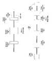
- FIG. 6illustrates a method, according to various embodiments of the invention.
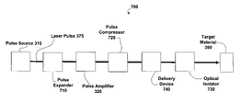
- FIGS. 7A , 7 B and 7 Cillustrate a chirped pulse application system including a post amplification optical isolator, according to various embodiments of the invention.
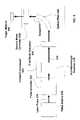
- FIG. 8illustrates methods of using the system illustrated in FIGS. 7A , 7 B and 7 C, according to various embodiments of the invention.
- polarization sensitive optical componentsare configured for pulse compression and as a polarization unit of an optical isolator.
- these polarization dependent componentsmay include one or more gratings, a mode converter and Bragg fiber, or the like. Embodiments of the invention have been found to result in up to a 98% transmission efficiency while achieving the same optical isolation as prior art systems.
- FIG. 3illustrates a combination optical isolator and pulse compression system (Isolator/Compressor 300 ).
- Isolator/Compressor 300is configured to receive a laser pulse from a Pulse Source 310 , optionally following amplification by a Pulse Amplifier 320 .
- Pulse Source 310 and Pulse Amplifier 320can include any of the variety of pulse sources and amplifiers that are known in the art.
- Pulse Source 310includes a ring laser and Pulse Amplifier 320 includes a fiber optic amplifier.
- a pulse expander(not shown) is optionally included between Pulse Source 310 and Pulse Amplifier 320 .
- Pulse Source 310 , Pulse Amplifier 320 and Isolator/Compressor 300comprise components of a chirped pulse amplification system.
- Isolator/Compressor 300includes a Polarizer 330 , a Faraday Rotator 340 , a First Compression Grating 350 , a Second Compression Grating 360 and a Reflector 370 .
- Polarizer 330is configured to linearly polarize a Laser Pulse 375 received from Pulse Source 310 or Pulse Amplifier 320 , and to prevent transmission of light through Isolator/Compressor 300 to Pulse Source 310 or Pulse Amplifier 320 as is further discussed herein.
- Polarizer 330is a polarization unit including birefringent polarizers such as Wollaston, Glan-Thompson or Glan-Foucault prisms, reflection polarizers, or dichroic polarizers.
- Polarizerscan also be based on subwavelength gratings. Such components are sometimes referred to as wire-grid polarizers and can be made out of multilayer gratings or parallel metal wires that reflect one polarization while transmitting the other.
- Other examples of polarization-sensitive subwavelength gratingscan be found in Selected papers on subwavelength diffractive optics /editors Joseph N. Mait, Dennis W. Prather (SPIE milestones series; v. MS 166).
- Faraday Rotator 340is configured to rotate light using the Faraday effect. Therefore, Faraday Rotator 340 is typically placed within or includes a magnetic field. In some embodiments, Faraday Rotator 340 is configured to rotate the polarization of light received from Polarizer 330 by 45 degrees. As a result of the Faraday effect, the absolute direction of this rotation is dependent on the direction of the magnetic field not the direction of travel of the light. The absolute direction of this rotation relative to a coordinate system of Isolator/Compressor 300 will be independent of the direction of travel of a light pulse through Faraday Rotator 340 .
- Second Compression Grating 350is typically configured to receive light at a polarization of 45 degrees from that of Polarizer 330 .
- First Compression Grating 350in combination with Second Compression Grating 360 and Reflector 370 , is configured to modify a temporal length of a laser pulse, e.g., to temporally compress (or expand) an optical pulse received from Pulse Source 310 or Pulse Amplifier 320 .
- First Compression Grating 350in combination with Second Compression Grating 360 also comprise a second polarization unit of Isolator/Compressor 300 . Compression is achieved by separating light within a laser pulse according to component wavelengths, providing a slight path length variation according to wavelength and then recombining the separated wavelengths.
- Optional Reflector 370is configured to reflect the laser pulse back for a second pass between First Compression Grating 350 and Second Compression Grating 360 .
- an Output 377 of Isolator/Compressor 300is obtained from a surface of First Compressing Grating 350 .
- Output 377is optionally passed through a Delivery Device 380 to a Target Material 390 .
- Delivery Device 380includes optics configured for directing a light pulse such as a lens, a reflector, a prism, a fiber optic, or the like.
- Delivery Device 380includes a fiber optic, Bragg fiber, or optical collimator. Delivery Device 380 may or may not be a polarizing device.
- Target Material 390is a material configured to be modified, altered, treated or otherwise receive Output 377 .
- Target Material 390is a material to be ablated using Output 377 , a tissue to receive therapeutic light, a semiconductor wafer being modified to produce integrated circuits or sensors, a metal component being micro-machined into objects such as stents and automotive fuel injectors, or the like.
- Isolator/Compressor 300is configured to operate as an optical isolator.
- Isolator/Compressor 300is configured to prevent light from traveling in the “reverse” direction, e.g., from Target Material 390 towards Pulse Source 310 .
- Light traveling in this directionis linearly polarized by interaction with First Compression Grating 350 and Second Compression Grating 360 .
- This polarized lightthen passes through Faraday Rotator 340 where the plane of polarization is rotated by 45 degrees. This rotation is in the same absolute direction as the rotation experienced by light traveling in the forward direction.
- Faraday Rotator 340light traveling in the reverse direction is polarized 90 degrees from the polarization of Polarizer 330 .
- Isolator/Compressor 300functions as an optical isolator. In some embodiments, Isolator/Compressor 300 has a transmission greater than 90% in the forward direction and block 99.9% of the light traveling in the reverse direction.
- Isolator/Compressor 300is configured to prevent light from traveling from Delivery Device 380 to Pulse Amplifier 320 .
- light scattered or reflected from a surface of Delivery Device 380e.g., an entrance facet
- Isolator/Compressor 300is configured to prevent light from traveling in this direction and is (optionally) disposed between Delivery Device 380 and Pulse Amplifier 320 , most of this light is prevented from reaching Pulse Amplifier 320 .
- Isolator/Compressor 300 or Isolator 100is configured to prevent light from traveling in the direction from Target Material 390 to Pulse Amplifier 320 .
- Isolator/Compressor 300is optionally disposed between Target Material 390 and Delivery Device 380 , between Delivery Device 380 and Pulse Amplifier 320 , or elsewhere between Pulse Amplifier 320 and Target Material 390 .
- Light traveling from Target Material 390may result from a laser pulse being reflected from Target Material 390 , from spontaneous emission or Rayleigh scattering occurring at a surface of Target Material 390 following generation of plasma by an ablation pulse, from fluorescence of Target Material 390 resulting from a laser pulse, or the like.
- Lightmay also be reflected from a surface of Delivery Device 380 or some other optic between Pulse Amplifier 320 and Target Material 390 .
- Isolator/Compressor 300is configured to prevent light from traveling from Pulse Amplifier 320 to Pulse Source 310 .
- Isolator/Compressor 300is optionally disposed between Pulse Amplifier 320 and Pulse Source 310 .
- Light traveling from Target Material 390may result from a laser pulse being reflected from Target Material 390 , from Rayleigh scattering occurring at a surface of Target Material 390 following generation of a plasma by an ablation pulse, from fluorescence of Target Material 390 resulting from an ablation pulse, from spontaneous emission within Pulse Amplifier 320 , from amplification within Pulse Amplifier 320 , or the like.
- FIG. 4illustrates an Isolator/Compressor 400 , including a Sub-Wavelength Polarizer 410 .
- Isolator/Compressor 400is an alternative embodiment of Isolator/Compressor 300 .
- Sub-Wavelength Polarizer 410is configured to perform the functions of both Polarizer 330 and Faraday Rotator 340 , and may comprise a first polarization unit of Isolator/Compressor 400 .
- Sub-Wavelength Polarizer 410includes a magnetized garnet or other material that produces the Faraday effect, and an etched or burned grating.
- Sub-Wavelength Polarizer 410is a sub-wavelength polarizer available from NanoOpto Corporation of Somerset, N.J.
- FIG. 5illustrates an Isolator/Compressor 500 including at least one mode converter configured to change a polarization mode of a light pulse and an optical fiber configured to modify (e.g., compress or expand) the temporal length of the light pulse.
- Isolator/Compressor 500is an alternative embodiment of Isolator/Compressor 300 .
- the embodiments of Isolator/Compressor 500 illustrated by FIG. 5include a First Mode Converter 510 , an Optical Fiber 520 and an optional Second Mode Converter 530 , which comprise a second polarization unit. These elements perform functions similar to those of First Compression Grating 350 and Second Compression Grating 360 , and are optionally used as replacements for First Compression Grating 350 and Second Compression Grating 360 .
- First Mode Converter 510 , Optical Fiber 520 and Second Mode Converter 530are configured to compress (or expand) a laser pulse while also functioning as part of an optical isolator.
- First Mode Converter 510can be configured to compress a laser pulse
- Optical Fiber 520includes a fiber Bragg Grating or a Bragg fiber (e.g., a hollow core fiber).
- First Mode Converter 510can be configured to convert linearly polarized light received from Sub-Wavelength Polarizer 410 or Polarizer 330 to a polarization mode better suited for introduction and passage through Optical Fiber 520 .
- First Mode Converter 510is configured to convert laser pulses from a LP 01 mode to a TE 01 mode.
- Optional Second Mode converter 510is configured to convert laserpulses back from the TE 01 mode to a LP 01 mode for delivery to Target Material 390 .
- First Mode Converter 510Optical Fiber 520 and Second Mode Converter 530 can operate as part of an optical isolator (e.g., Isolator/Compressor 300 ) because the transmission characteristics of Optical Fiber 520 are polarization dependent.
- Optical Fiber 520 and First Mode Converter 510are configured such that light traveling in the “reverse” direction (toward Pulse Source 310 ) will have a polarization that will cause the light to be blocked at Sub-Wavelength Polarizer 410 or Polarizer 330 .
- Optical Fiber 520For example, light passing back through Optical Fiber 520 in the direction from Target Material 390 towards Pulse Source 310 and in modes other than the TE 01 mode (e.g., a TM 01 mode) can suffer high loss rates in a hollow core fiber. Thus, a significant fraction of any light that successfully passes through Optical Fiber 520 and travels toward First Mode Converter 510 will be in the TE 01 mode. At First Mode Converter 510 , this light is converted from the TE 01 mode to the LP 01 mode. First Mode Converter 510 is configured such that this converted light will not have the linear polarization angle required to pass through Sub-Wavelength Polarizer 410 or Polarizer 330 following Faraday rotation. Optical isolation is, therefore, achieved.
- First Mode Converter 510 and Optical Fiber 520are part of an instance of Isolator/Compressor 300 disposed between Pulse Source 310 and Pulse Amplifier 320 .
- Isolator/Compressor 300is configured to isolate and expand (rather than compress) laser pulses. Further in these embodiments, the order of Sub-Wavelength Polarizer (or Polarizer 330 and Faraday Rotator 340 ), First Mode Converter 510 and Optical Fiber 520 may be reversed.
- FIG. 6illustrates a method according to various embodiments of the invention.
- lightis allowed to pass through Isolator/Compressor 300 in a forward direction and prevented from passing in the reverse direction through Isolator/Compressor 300 .
- a light pulsee.g. Laser Pulse 375
- a first polarization unitFor example, a light pulse traveling along a beam path in a forward direction, away from Pulse Source 310 , may be received by Polarizer 330 or Sub-Wavelength Polarizer 410 .
- This light pulsemay or may not have been amplified by Pulse Amplifier 320 .
- the received light pulseis polarized by the first polarization unit.
- Modify Polarization Step 620the polarization of the received light pulse is modified.
- the polarizationmay be rotated using Faraday Rotator 340 or Sub-Wavelength Polarizer 410 .
- Modify Polarization Step 620optionally further includes changing a polarization mode of the light pulse using First Mode Converter 510 .
- a Compress Step 630the received light pulse is compressed.
- compressionis accomplished using First Compression Grating 350 and Second Compression Grating 360 .
- compressionis accomplished using Optical Fiber 520 .
- the components used for pulse compressioncomprise a second polarization unit of Isolator/Compressor 300 .
- the compressed light pulseis delivered to Delivery Device 380 , Target Material 390 , and/or another optical component.
- This deliverymay result in one or more back reflections, e.g., from a surface of Delivery Device 380 and/or Target Material 390 .
- This deliverymay also result in emission of light from plasma formed by the light pulse striking Target Material 390 .
- Isolator/Compressor 300is used to block the back reflections, plasma generated light or any other light traveling in the “reverse” direction. This blocking occurs because the light is polarized as it passes through the second polarization unit, for example, comprising First Compression Grating 350 and Second Compression Grating 360 , or First Mode Converter 510 and Optical Fiber 520 . After being polarized by the second polarization unit and then rotated by a Faraday rotator, such as Faraday Rotator 340 or Sub-Wavelength Polarizer 410 , the light is polarized such that it is blocked by the first polarization unit.
- a Faraday rotatorsuch as Faraday Rotator 340 or Sub-Wavelength Polarizer 410
- the method illustrated in FIG. 6is adapted for embodiments in which Isolator/Compressor 300 is configured for expansion rather than compression of a light pulse.
- the first polarization unitmay include Optical Fiber 520 , or First Compression Grating 350 and Second Compression Grating 360 .
- the light blocked in Block Step 650may result from Pulse Amplifier 320 .
- FIGS. 7A , 7 B and 7 Cillustrate a chirped pulse application system, generally designated 700 , including a post amplification optical isolator, according to various embodiments of the invention.
- a pulse compressor and an optical isolatorcan, but do not necessarily, have components in common.
- Chirped Pulse Application System 700includes Pulse Source 310 configured to provide Laser Pulse 375 .
- Laser Pulse 375may be expanded in time (e.g., stretched) using an optional Pulse Expander 710 .
- Laser Pulse 375is amplified to generate an amplified laser pulse using one or more instances of Pulse Amplifier 320 , and compressed using an optional Pulse Compressor 720 .
- Pulse Expander 710 and Pulse Compressor 720are optionally instances of Pulse Expander 220 and Pulse Compressor 250 , respectively.
- Pulse Expander 710 and Pulse Compressor 720include gratings, a Bragg fiber, and/or the like.
- Chirped Pulse Application System 700further includes an Optical Isolator 730 .
- Optical Isolator 730is configured to allow light to pass in a first direction and to block light from passing in a second direction.
- Optical Isolator 730shares components with Pulse Compressor 720 , e.g., Optical Isolator 730 includes Isolator/Compressor 300 , Isolator/Compressor 400 , Isolator/Compressor 500 , or the like.
- Optical Isolator 730is separate from Pulse Compressor 720 .
- Optical Isolator 730is configured to prevent light from traveling from a Delivery Device 740 and/or Target Material 390 to Pulse Amplifier 320 . This light may result from the amplified laser pulse generated using Pulse Amplifier 320 . For example, in some embodiments, when the amplified laser pulse strikes Target Material 390 , light is produce through Rayleigh scattering, fluorescence, plasma generation, reflection, the photoelectric effect, spontaneous emission, or the like. In some embodiments, Optical Isolator 730 is configured to prevent light generated by reflection, fluorescence, etc. within Delivery Device 740 from traveling to Pulse Amplifier 320 . For example, Optical. Isolator 730 may be configured to prevent a fraction of the amplified laser pulse reflected from a surface within Delivery Device 740 from reaching Pulse Amplifier 320 .
- Optical Isolator 730prevents light from Delivery Device 740 and/or Target Material 390 from reaching any instances of Pulse Amplifier 320 included in Chirped Pulse Amplification System 700 .
- Optical Isolator 730can be disposed between Target Material 390 and Delivery Device 740 , or between Delivery Device 740 and Pulse Amplifier 320 .
- a separate Optical Isolator 730is disposed between Pulse Compressor 720 and Delivery Device 740 . These embodiments are illustrated in FIG. 7A .
- a separate Optical Isolator 730is disposed between Pulse Amplifier 320 and Pulse Compressor 720 .
- Optical Isolator 730may be disposed between Target Material 390 and Delivery Device 740 . These embodiments are illustrated in FIG. 7C .
- Delivery Device 740includes part of Optical Isolator 730 .
- Optical Isolator 730is optionally further configured to compress the amplified laser pulse.
- Delivery Device 740includes part of both Optical Isolator 730 and Pulse Compressor 720 .
- Delivery Device 740is configured to deliver the amplified laser pulse to Target Material 390 .
- Delivery Device 740is configured to deliver the amplified laser pulse to the surface of a body, to a material to be machined, to a surface to be ablated, or the like.
- Delivery Device 740is configured to deliver the amplified laser pulse to the interior of a body.
- at least part of Optical Isolator 730 and/or Pulse Compressor 720is optionally configured to enter the body.
- Second Mode Converter 530may be configured to enter the body.
- Delivery Device 740is an embodiment of Delivery Device 380 .
- FIG. 8illustrates methods of using the system illustrated in FIGS. 7A and 7B , according to various embodiments of the invention.
- a laser pulseis generated and delivered to a target material.
- Lightis prevented from traveling back in the direction from the target material toward a source of the laser pulse, using an optical isolator.
- the optical isolatoris optionally disposed between the target material and one or more pulse amplifiers configured for using in generating the laser pulse.
- light resulting from the amplified laser pulsemay be prevented from reaching any of the one or more pulse amplifiers.
- greater than 90%, 99% or 99.9% of the light resulting from the amplified laser pulseis prevented from reaching any of the one or more pulse amplifiers.
- a laser pulseis generated. This generation may be accomplished using Pulse Source 310 .
- Generate Pulse Step 810optionally includes expansion of a pulse generated by an optical oscillator, using Pulse Expander 710 .
- This laser pulseis amplified in an Amplify Pulse Step 820 .
- Amplify Pulse Step 820results in an amplified pulse and may be accomplished using Pulse Amplifier 720 .
- a Compress Pulse Step 830the amplified pulse is compressed using Pulse Compressor 720 .
- a Deliver Pulse Step 840the amplified pulse compressed in Compress Pulse Step 830 is delivered using Delivery Device 740 to Target Material 390 .
- lightmay result from the amplified pulse through a variety of processes. For example, light may be generated by scattering, fluorescence or reflection from a surface of Delivery Device 170 . Alternatively, light may be generated by Rayleigh scattering or other processes discussed herein, when the amplified pulse strikes Target Material 390 .
- Compress Pulse Step 830is performed contemporaneously with Deliver Pulse Step 840 .
- a Block Step 850light resulting from delivery of the amplified pulse to Target Material 390 is prevented from reaching any of the instances of Pulse Amplifier 320 that were used to generate the amplified pulse.
- the preventionis accomplished using Optical Isolator 730 .
- Isolator/Compressor 300is disposed between Pulse Source 310 and Pulse Amplifier 320 .
- Faraday Rotator 340 and a quarter-wave plateare disposed between First Compression Grating 350 and Second Compression Grating 360 such that a laser pulse passes through Faraday Rotator 340 and the quarter-wave plate on one pass between First Compression Grating 350 and Second Compression Grating 360 but not on a second pass.
- Polarizer 330 and Sub-Wavelength Polarizer 410are optional. It is anticipated that, Isolator/Compressor 300 may be used in applications other than chirped pulse amplification. For example, Isolator/Compressor 300 may be used in communication systems or ring lasers.
- post amplification optical isolationWhile the examples of post amplification optical isolation discussed herein are described in relation to a chirped pulse amplification system, the use of post amplification optical isolation is intended to be applicable to other laser systems in which it is desirable to prevent the transmission of light back from a delivery device or a target material to the last amplifier in a laser pulse source.
- Delivery Device 740 and Optical Isolator 730share components, or Optical Isolator 730 and Pulse Compressor 720 share components, are applicable to other laser systems.
Landscapes
- Physics & Mathematics (AREA)
- Electromagnetism (AREA)
- Engineering & Computer Science (AREA)
- Plasma & Fusion (AREA)
- Optics & Photonics (AREA)
- Lasers (AREA)
Abstract
Description
Claims (22)
Priority Applications (1)
| Application Number | Priority Date | Filing Date | Title |
|---|---|---|---|
| US11/333,824US7139116B1 (en) | 2005-11-30 | 2006-01-17 | Post amplification optical isolator |
Applications Claiming Priority (2)
| Application Number | Priority Date | Filing Date | Title |
|---|---|---|---|
| US11/291,609US7436866B2 (en) | 2005-11-30 | 2005-11-30 | Combination optical isolator and pulse compressor |
| US11/333,824US7139116B1 (en) | 2005-11-30 | 2006-01-17 | Post amplification optical isolator |
Related Parent Applications (1)
| Application Number | Title | Priority Date | Filing Date |
|---|---|---|---|
| US11/291,609Continuation-In-PartUS7436866B2 (en) | 2005-11-30 | 2005-11-30 | Combination optical isolator and pulse compressor |
Publications (1)
| Publication Number | Publication Date |
|---|---|
| US7139116B1true US7139116B1 (en) | 2006-11-21 |
Family
ID=37423249
Family Applications (2)
| Application Number | Title | Priority Date | Filing Date |
|---|---|---|---|
| US11/291,609Expired - Fee RelatedUS7436866B2 (en) | 2005-11-30 | 2005-11-30 | Combination optical isolator and pulse compressor |
| US11/333,824ActiveUS7139116B1 (en) | 2005-11-30 | 2006-01-17 | Post amplification optical isolator |
Family Applications Before (1)
| Application Number | Title | Priority Date | Filing Date |
|---|---|---|---|
| US11/291,609Expired - Fee RelatedUS7436866B2 (en) | 2005-11-30 | 2005-11-30 | Combination optical isolator and pulse compressor |
Country Status (1)
| Country | Link |
|---|---|
| US (2) | US7436866B2 (en) |
Cited By (5)
| Publication number | Priority date | Publication date | Assignee | Title |
|---|---|---|---|---|
| JP2007163579A (en)* | 2005-12-09 | 2007-06-28 | Furukawa Electric Co Ltd:The | Optical compressor and ultrashort pulse light source |
| US20090046746A1 (en)* | 2007-07-06 | 2009-02-19 | Deep Photonics Corporation | Pulsed fiber laser |
| US20120120466A1 (en)* | 2009-07-23 | 2012-05-17 | Ytel Photonics Inc. | Wavelength-tunable laser system |
| CN102891425A (en)* | 2011-10-11 | 2013-01-23 | 清华大学 | Ultrahigh peak power fiber amplification system for wide spectrum nanosecond pulsed light |
| CN118899736A (en)* | 2024-09-30 | 2024-11-05 | 成都市谐振光电有限公司 | One-way pyramid ring cavity and laser |
Families Citing this family (17)
| Publication number | Priority date | Publication date | Assignee | Title |
|---|---|---|---|---|
| US7361171B2 (en) | 2003-05-20 | 2008-04-22 | Raydiance, Inc. | Man-portable optical ablation system |
| US8921733B2 (en) | 2003-08-11 | 2014-12-30 | Raydiance, Inc. | Methods and systems for trimming circuits |
| US7486705B2 (en)* | 2004-03-31 | 2009-02-03 | Imra America, Inc. | Femtosecond laser processing system with process parameters, controls and feedback |
| US7885311B2 (en)* | 2007-03-27 | 2011-02-08 | Imra America, Inc. | Beam stabilized fiber laser |
| US8135050B1 (en) | 2005-07-19 | 2012-03-13 | Raydiance, Inc. | Automated polarization correction |
| US8189971B1 (en) | 2006-01-23 | 2012-05-29 | Raydiance, Inc. | Dispersion compensation in a chirped pulse amplification system |
| US8232687B2 (en) | 2006-04-26 | 2012-07-31 | Raydiance, Inc. | Intelligent laser interlock system |
| US9130344B2 (en) | 2006-01-23 | 2015-09-08 | Raydiance, Inc. | Automated laser tuning |
| US7444049B1 (en) | 2006-01-23 | 2008-10-28 | Raydiance, Inc. | Pulse stretcher and compressor including a multi-pass Bragg grating |
| US7822347B1 (en) | 2006-03-28 | 2010-10-26 | Raydiance, Inc. | Active tuning of temporal dispersion in an ultrashort pulse laser system |
| US7777940B1 (en) | 2007-02-09 | 2010-08-17 | University Of Central Florida Research Foundation, Inc. | Extreme chirped pulse amplification and phase control |
| US7903326B2 (en) | 2007-11-30 | 2011-03-08 | Radiance, Inc. | Static phase mask for high-order spectral phase control in a hybrid chirped pulse amplifier system |
| KR20140018183A (en) | 2010-09-16 | 2014-02-12 | 레이디안스, 아이엔씨. | Laser based processing of layered materials |
| US8554037B2 (en) | 2010-09-30 | 2013-10-08 | Raydiance, Inc. | Hybrid waveguide device in powerful laser systems |
| US9407053B2 (en)* | 2014-03-03 | 2016-08-02 | V-Gen Ltd. | Hybrid isolator and mode expander for fiber laser amplifiers |
| FR3043216B1 (en)* | 2015-10-28 | 2018-02-02 | Centre National De La Recherche Scientifique | PHOTONIC GENERATION DEVICE FOR ARBITRATIC FREQUENCY LINEAR MODULATION MICROWAVE SIGNALS |
| JP7621596B2 (en)* | 2021-03-19 | 2025-01-27 | ギガフォトン株式会社 | Ultraviolet laser apparatus, method and system for manufacturing electronic devices |
Citations (177)
| Publication number | Priority date | Publication date | Assignee | Title |
|---|---|---|---|---|
| US3631362A (en) | 1968-08-27 | 1971-12-28 | Gen Electric | Face-pumped, face-cooled laser device |
| US3808549A (en) | 1972-03-30 | 1974-04-30 | Corning Glass Works | Optical waveguide light source |
| US3963953A (en) | 1975-04-29 | 1976-06-15 | Westinghouse Electric Corporation | Color mismatch accentuating device |
| US4194813A (en)* | 1978-10-13 | 1980-03-25 | The United States Of America As Represented By The United States Department Of Energy | Vacuum aperture isolator for retroreflection from laser-irradiated target |
| US4289378A (en) | 1978-06-21 | 1981-09-15 | Ernst Remy | Apparatus for adjusting the focal point of an operating laser beam focused by an objective |
| US4718418A (en) | 1983-11-17 | 1988-01-12 | Lri L.P. | Apparatus for ophthalmological surgery |
| US4722591A (en) | 1986-03-17 | 1988-02-02 | Cincinnati Milacron Inc. | Laser beam combiner |
| US4750809A (en) | 1985-05-01 | 1988-06-14 | Spectra-Physics, Inc. | Pulse compression |
| US4808000A (en) | 1986-10-15 | 1989-02-28 | Union Oil Company Of California | Positioning device and method |
| US4815079A (en) | 1987-12-17 | 1989-03-21 | Polaroid Corporation | Optical fiber lasers and amplifiers |
| US4824598A (en) | 1987-10-20 | 1989-04-25 | The United States Of America As Represented By The United States Department Of Energy | Synthetic laser medium |
| US4829529A (en) | 1987-06-15 | 1989-05-09 | Spectra-Physics, Inc. | Laser diode pumped fiber lasers with pump cavity |
| US4902127A (en) | 1988-03-22 | 1990-02-20 | Board Of Trustees Of Leland Stanford, Jr. University | Eye-safe coherent laser radar |
| US4913520A (en) | 1988-10-25 | 1990-04-03 | Spectra Physics | Optical fiber for pulse compression |
| US4915757A (en) | 1988-05-05 | 1990-04-10 | Spectra-Physics, Inc. | Creation of three dimensional objects |
| US4972423A (en) | 1988-12-30 | 1990-11-20 | Alfano Robert R | Method and apparatus for generating ultrashort light pulses |
| US5014290A (en) | 1988-10-28 | 1991-05-07 | Moore Robert M | Method and apparatus for generating radiation blockers |
| US5022042A (en) | 1990-09-10 | 1991-06-04 | General Dynamics Corp. | High power laser array with stable wavelength |
| US5043991A (en) | 1989-12-28 | 1991-08-27 | General Dynamics Corp. Electronics Division | Device for compensating for thermal instabilities of laser diodes |
| US5132996A (en) | 1988-10-28 | 1992-07-21 | Kermath Manufacturing Company | X-ray imaging system with a sweeping linear detector |
| US5162643A (en) | 1991-02-26 | 1992-11-10 | Imra America, Inc. | Light detecting system |
| US5166818A (en) | 1991-03-11 | 1992-11-24 | Bell Communications Research, Inc. | Optical pulse-shaping device and method, and optical communications station and method |
| US5187759A (en) | 1991-11-07 | 1993-02-16 | At&T Bell Laboratories | High gain multi-mode optical amplifier |
| US5237576A (en) | 1992-05-05 | 1993-08-17 | At&T Bell Laboratories | Article comprising an optical fiber laser |
| US5265107A (en) | 1992-02-05 | 1993-11-23 | Bell Communications Research, Inc. | Broadband absorber having multiple quantum wells of different thicknesses |
| US5291501A (en) | 1989-12-22 | 1994-03-01 | University Of Southhampton | Optical fibre with doped core and doped inner cladding, for use in an optical fibre laser |
| US5302835A (en) | 1993-03-22 | 1994-04-12 | Imra America, Inc. | Light detection system having a polarization plane rotating means and a polarizing beamsplitter |
| US5313262A (en) | 1992-09-30 | 1994-05-17 | Imra America, Inc. | Systems and methods for object detection using beam widening optics |
| US5329398A (en) | 1992-11-05 | 1994-07-12 | Novatec Laser Systems, Inc. | Single grating laser pulse stretcher and compressor |
| US5367143A (en) | 1992-12-30 | 1994-11-22 | International Business Machines Corporation | Apparatus and method for multi-beam drilling |
| WO1994028972A1 (en) | 1993-05-14 | 1994-12-22 | Eberhard Oppold | Safety laser beam apertures (sla) for therapeutic and diagnostic medical equipment |
| US5400350A (en) | 1994-03-31 | 1995-03-21 | Imra America, Inc. | Method and apparatus for generating high energy ultrashort pulses |
| US5414725A (en) | 1993-08-03 | 1995-05-09 | Imra America, Inc. | Harmonic partitioning of a passively mode-locked laser |
| US5418809A (en) | 1994-05-31 | 1995-05-23 | General Electric Company | Modular slab assembly for a face-pumped laser |
| US5430572A (en) | 1993-09-30 | 1995-07-04 | At&T Corp. | High power, high gain, low noise, two-stage optical amplifier |
| US5440573A (en) | 1994-03-22 | 1995-08-08 | Imra America, Inc. | Method and apparatus for controlling laser emmision wavelength using non-linear effects |
| US5450427A (en) | 1994-10-21 | 1995-09-12 | Imra America, Inc. | Technique for the generation of optical pulses in modelocked lasers by dispersive control of the oscillation pulse width |
| US5479422A (en) | 1994-08-12 | 1995-12-26 | Imra America, Inc. | Controllabel dual-wavelength operation of modelocked lasers |
| US5489984A (en) | 1994-04-01 | 1996-02-06 | Imra America, Inc. | Differential ranging measurement system and method utilizing ultrashort pulses |
| US5499134A (en) | 1994-08-24 | 1996-03-12 | Imra America | Optical pulse amplification using chirped Bragg gratings |
| US5517043A (en) | 1994-10-25 | 1996-05-14 | Dalsa, Inc. | Split pixel interline transfer imaging device |
| US5548098A (en) | 1993-03-25 | 1996-08-20 | Mitsubishi Denki Kabushiki Kaisha | Laser cutting machine |
| US5572335A (en) | 1994-04-01 | 1996-11-05 | Xerox Corporation | Method and system for transferring image data between two devices having different bandwidths |
| US5572358A (en) | 1994-12-16 | 1996-11-05 | Clark-Mxr, Inc. | Regenerative amplifier incorporating a spectral filter within the resonant cavity |
| US5585652A (en) | 1994-10-25 | 1996-12-17 | Dalsa, Inc. | Method and apparatus for real-time background illumination subtraction |
| US5585913A (en) | 1994-04-01 | 1996-12-17 | Imra America Inc. | Ultrashort pulsewidth laser ranging system employing a time gate producing an autocorrelation and method therefore |
| US5592327A (en) | 1994-12-16 | 1997-01-07 | Clark-Mxr, Inc. | Regenerative amplifier incorporating a spectral filter within the resonant cavity |
| US5596668A (en) | 1995-06-30 | 1997-01-21 | Lucent Technologies Inc. | Single mode optical transmission fiber, and method of making the fiber |
| US5602677A (en) | 1993-05-18 | 1997-02-11 | Thomson-Csf | Dispersive optical delay line and use thereof for the compression/expansion of laser pulses |
| US5617434A (en) | 1994-06-30 | 1997-04-01 | Massachusetts Inst. Of Technology | Stretched-pulse fiber laser |
| US5627848A (en) | 1995-09-05 | 1997-05-06 | Imra America, Inc. | Apparatus for producing femtosecond and picosecond pulses from modelocked fiber lasers cladding pumped with broad area diode laser arrays |
| US5633885A (en) | 1994-09-29 | 1997-05-27 | Imra America, Inc. | Frequency chirp control and compensation for obtaining broad bandwidth ultrashort optical pulses from wavelength-tunable lasers |
| US5633750A (en) | 1995-05-01 | 1997-05-27 | Ando Electric Co., Ltd. | Optical fiber amplifier |
| US5651018A (en) | 1993-01-07 | 1997-07-22 | Sdl, Inc. | Wavelength-stabilized, high power semiconductor laser |
| US5656186A (en) | 1994-04-08 | 1997-08-12 | The Regents Of The University Of Michigan | Method for controlling configuration of laser induced breakdown and ablation |
| US5663731A (en) | 1995-08-25 | 1997-09-02 | Imra America, Inc. | Method and apparatus for time invariant pulse detection |
| US5677769A (en) | 1995-05-30 | 1997-10-14 | Imra America | Optical sensor utilizing rare-earth-doped integrated-optic lasers |
| US5689519A (en) | 1993-12-20 | 1997-11-18 | Imra America, Inc. | Environmentally stable passively modelocked fiber laser pulse source |
| US5696782A (en)* | 1995-05-19 | 1997-12-09 | Imra America, Inc. | High power fiber chirped pulse amplification systems based on cladding pumped rare-earth doped fibers |
| US5701319A (en) | 1995-10-20 | 1997-12-23 | Imra America, Inc. | Method and apparatus for generating ultrashort pulses with adjustable repetition rates from passively modelocked fiber lasers |
| US5703639A (en) | 1994-10-25 | 1997-12-30 | Dalsa, Inc. | Charge coupled device pulse discriminator |
| US5708669A (en) | 1996-09-24 | 1998-01-13 | Lucent Technologies Inc. | Article comprising a cladding-pumped optical fiber laser |
| US5710424A (en) | 1995-10-18 | 1998-01-20 | Imra America, Inc. | Multiple field of view detector with background cancellation |
| US5720894A (en) | 1996-01-11 | 1998-02-24 | The Regents Of The University Of California | Ultrashort pulse high repetition rate laser system for biological tissue processing |
| US5726855A (en) | 1995-08-15 | 1998-03-10 | The Regents Of The University Of Michigan | Apparatus and method for enabling the creation of multiple extended conduction paths in the atmosphere |
| US5778016A (en) | 1994-04-01 | 1998-07-07 | Imra America, Inc. | Scanning temporal ultrafast delay methods and apparatuses therefor |
| US5818630A (en) | 1997-06-25 | 1998-10-06 | Imra America, Inc. | Single-mode amplifiers and compressors based on multi-mode fibers |
| US5822097A (en) | 1993-11-19 | 1998-10-13 | Thomson-Csf | Linear extension device for coherent optical wave pulses and extension and compression device used to obtain high power pulses |
| US5847863A (en) | 1996-04-25 | 1998-12-08 | Imra America, Inc. | Hybrid short-pulse amplifiers with phase-mismatch compensated pulse stretchers and compressors |
| US5862287A (en) | 1996-12-13 | 1999-01-19 | Imra America, Inc. | Apparatus and method for delivery of dispersion compensated ultrashort optical pulses with high peak power |
| US5862845A (en)* | 1998-05-19 | 1999-01-26 | Universite Laval | Use of ultrafast intense laser for processing lignocellulosic material |
| US5867304A (en) | 1997-04-25 | 1999-02-02 | Imra America, Inc. | Use of aperiodic quasi-phase-matched gratings in ultrashort pulse sources |
| US5875408A (en) | 1995-07-17 | 1999-02-23 | Imra America, Inc. | Automated vehicle guidance system and method for automatically guiding a vehicle |
| US5880823A (en) | 1994-06-10 | 1999-03-09 | Lu; Chih-Shun | Method and apparatus for measuring atomic vapor density in deposition systems |
| US5880877A (en) | 1997-01-28 | 1999-03-09 | Imra America, Inc. | Apparatus and method for the generation of high-power femtosecond pulses from a fiber amplifier |
| US5898485A (en) | 1995-03-31 | 1999-04-27 | Imra America, Inc. | Method and apparatus for multiple target ranging |
| US5907157A (en) | 1996-02-01 | 1999-05-25 | Jeol Ltd. | Method and apparatus for preparing specimen |
| US5920668A (en) | 1997-10-24 | 1999-07-06 | Imra America, Inc. | Compact fiber laser unit |
| US5936716A (en) | 1996-05-31 | 1999-08-10 | Pinsukanjana; Paul Ruengrit | Method of controlling multi-species epitaxial deposition |
| US6020591A (en) | 1997-07-11 | 2000-02-01 | Imra America, Inc. | Two-photon microscopy with plane wave illumination |
| US6034975A (en) | 1998-03-09 | 2000-03-07 | Imra America, Inc. | High power, passively modelocked fiber laser, and method of construction |
| US6061373A (en) | 1998-10-13 | 2000-05-09 | Tyco Submarine Systems, Ltd. | Safety interlocking system for an optical fiber amplifier and pump source |
| US6072811A (en) | 1998-02-11 | 2000-06-06 | Imra America | Integrated passively modelocked fiber lasers and method for constructing the same |
| US6075588A (en) | 1996-05-31 | 2000-06-13 | The Regents Of The University Of California | Integrated multi-channel optical-based flux monitor and method |
| US6081369A (en) | 1996-01-19 | 2000-06-27 | Sdl., Inc. | Fiber amplifiers and pumping sources for fiber amplifiers |
| US6120857A (en) | 1998-05-18 | 2000-09-19 | The Regents Of The University Of California | Low work function surface layers produced by laser ablation using short-wavelength photons |
| US6130780A (en) | 1998-02-19 | 2000-10-10 | Massachusetts Institute Of Technology | High omnidirectional reflector |
| US6151338A (en) | 1997-02-19 | 2000-11-21 | Sdl, Inc. | High power laser optical amplifier system |
| US6154310A (en) | 1997-11-21 | 2000-11-28 | Imra America, Inc. | Ultrashort-pulse source with controllable multiple-wavelength output |
| US6156030A (en) | 1997-06-04 | 2000-12-05 | Y-Beam Technologies, Inc. | Method and apparatus for high precision variable rate material removal and modification |
| US6181463B1 (en) | 1997-03-21 | 2001-01-30 | Imra America, Inc. | Quasi-phase-matched parametric chirped pulse amplification systems |
| US6198568B1 (en) | 1997-04-25 | 2001-03-06 | Imra America, Inc. | Use of Chirped Quasi-phase-matched materials in chirped pulse amplification systems |
| US6208458B1 (en) | 1997-03-21 | 2001-03-27 | Imra America, Inc. | Quasi-phase-matched parametric chirped pulse amplification systems |
| US6246816B1 (en) | 1999-07-30 | 2001-06-12 | Litton Systems, Inc. | Wavelength stabilized laser light source |
| US6249630B1 (en) | 1996-12-13 | 2001-06-19 | Imra America, Inc. | Apparatus and method for delivery of dispersion-compensated ultrashort optical pulses with high peak power |
| US6252892B1 (en) | 1998-09-08 | 2001-06-26 | Imra America, Inc. | Resonant fabry-perot semiconductor saturable absorbers and two photon absorption power limiters |
| US6256328B1 (en) | 1998-05-15 | 2001-07-03 | University Of Central Florida | Multiwavelength modelocked semiconductor diode laser |
| US6269108B1 (en) | 1999-05-26 | 2001-07-31 | University Of Central Florida | Multi-wavelengths infrared laser |
| US6275250B1 (en)* | 1998-05-26 | 2001-08-14 | Sdl, Inc. | Fiber gain medium marking system pumped or seeded by a modulated laser diode source and method of energy control |
| US6275512B1 (en) | 1998-11-25 | 2001-08-14 | Imra America, Inc. | Mode-locked multimode fiber laser pulse source |
| US6303903B1 (en) | 1999-08-11 | 2001-10-16 | Matsushita Electric Industrial Co., Ltd | Method and apparatus for determining focus position of a laser |
| US6314115B1 (en) | 1998-05-15 | 2001-11-06 | University Of Central Florida | Hybrid WDM-TDM optical communication and data link |
| US6327074B1 (en) | 1998-11-25 | 2001-12-04 | University Of Central Florida | Display medium using emitting particles dispersed in a transparent host |
| US6327282B2 (en) | 1999-02-02 | 2001-12-04 | University Of Central Florida | Yb-doped:YCOB laser |
| US6335821B1 (en) | 1999-02-10 | 2002-01-01 | Oki Electric Industrial Co. Ltd. | Optical fiber amplifier and a method for controlling the same |
| US6355908B1 (en) | 1999-03-31 | 2002-03-12 | Matsushita Electric Industrial Co., Ltd. | Method and apparatus for focusing a laser |
| US6362454B1 (en) | 1999-10-01 | 2002-03-26 | Matsushita Electric Industrial Co., Ltd. | Method for drilling circular holes with a laser beam |
| US6365869B1 (en) | 2000-08-11 | 2002-04-02 | Matsushita Electric Industrial Co., Ltd. | Apparatus for laser processing foil material |
| US6370171B1 (en) | 1998-09-21 | 2002-04-09 | Armin Horn | Laser machine tool |
| US6404944B1 (en) | 2000-03-17 | 2002-06-11 | Unveristy Of Central Florida | Monolithic integrated active semiconductor optical switch for a 1×N interconnect switch |
| US6421169B1 (en) | 1997-02-14 | 2002-07-16 | Telefonaktiebolaget Lm Ericsson | Optical fiber amplifier having variable gain |
| US6433305B1 (en) | 1999-12-23 | 2002-08-13 | Matsushita Electric Industries Co., Ltd. | Method and apparatus for drilling holes with sub-wavelength pitch with laser |
| US6433760B1 (en) | 1999-01-14 | 2002-08-13 | University Of Central Florida | Head mounted display with eyetracking capability |
| US6433303B1 (en) | 2000-03-31 | 2002-08-13 | Matsushita Electric Industrial Co., Ltd. | Method and apparatus using laser pulses to make an array of microcavity holes |
| US20020176676A1 (en) | 2001-01-25 | 2002-11-28 | Johnson Steven G. | Photonic crystal optical waveguides having tailored dispersion profiles |
| US6522460B2 (en) | 1998-07-17 | 2003-02-18 | Telefonaktiebolaget Lm Ericsson (Publ) | Optical fiber amplifier control |
| US6525873B2 (en) | 2000-04-13 | 2003-02-25 | Corning Incorporated | Optical amplifiers with a simple gain/output control device |
| US6526327B2 (en) | 1998-01-12 | 2003-02-25 | University Of Central Florida | One-step rapid manufacturing of metal and composite parts |
| US6529319B2 (en) | 2000-12-14 | 2003-03-04 | Electronics And Telecommunications Research Institute | Automatic gain-controlled optical fiber amplifier |
| US6573813B1 (en) | 1999-04-23 | 2003-06-03 | Massachusetts Institute Of Technology | All-dielectric coaxial waveguide with annular sections |
| US6574024B1 (en) | 2000-03-31 | 2003-06-03 | Matsushita Electric Industrial Co., Ltd. | Laser beam homogenization by scanning a beam onto a mask |
| US6576917B1 (en) | 1997-03-11 | 2003-06-10 | University Of Central Florida | Adjustable bore capillary discharge |
| US6580553B2 (en) | 2001-07-10 | 2003-06-17 | Samsung Electronics Co., Ltd | Automatic gain control device of optical fiber amplifier |
| JP2003181661A (en) | 2001-12-18 | 2003-07-02 | Nec Corp | Laser pulse irradiation method and ultra-short pulse laser apparatus |
| US6597497B2 (en) | 2001-10-04 | 2003-07-22 | Shih-Yuan Wang | Semiconductor optical amplifier with transverse laser cavity intersecting optical signal path and method of fabrication thereof |
| US6603911B2 (en) | 1998-10-14 | 2003-08-05 | Massachusetts Institute Of Technology | Omnidirectional multilayer device for enhanced optical waveguiding |
| US6621045B1 (en) | 2002-07-25 | 2003-09-16 | Matsushita Electric Industrial Co., Ltd. | Workpiece stabilization with gas flow |
| US6627844B2 (en) | 2001-11-30 | 2003-09-30 | Matsushita Electric Industrial Co., Ltd. | Method of laser milling |
| US6642477B1 (en) | 2001-10-23 | 2003-11-04 | Imra America, Inc. | Method for laser drilling a counter-tapered through-hole in a material |
| US6654161B2 (en) | 1998-11-25 | 2003-11-25 | University Of Central Florida | Dispersed crystallite up-conversion displays |
| US6661816B2 (en) | 1998-06-11 | 2003-12-09 | University Of Central Florida | Multiwavelength modelocked lasers |
| US6671298B1 (en) | 2002-05-22 | 2003-12-30 | University Of Central Florida | Photonic arbitrary waveform generation and RF and microwave synthesis with a modelocked external cavity semi-conductor laser |
| US6677552B1 (en) | 2001-11-30 | 2004-01-13 | Positive Light, Inc. | System and method for laser micro-machining |
| US6690686B2 (en) | 1998-05-15 | 2004-02-10 | University Of Central Florida | Method for reducing amplitude noise in multi-wavelength modelocked semiconductor lasers |
| US6710293B2 (en) | 2002-07-25 | 2004-03-23 | Matsushita Electric Industrial Co., Ltd. | System for and method of custom microfilter design with beamsplitter characterization |
| US6710288B2 (en) | 2002-07-25 | 2004-03-23 | Matsushita Electric Industrial Co., Ltd. | Method and apparatus for aligning a work piece in a laser drilling system |
| US6720519B2 (en) | 2001-11-30 | 2004-04-13 | Matsushita Electric Industrial Co., Ltd. | System and method of laser drilling |
| US6723991B1 (en) | 2000-10-20 | 2004-04-20 | Imra America, Inc. | Single-shot differential spectroscopy and spectral-imaging at submillimeter wavelengths |
| US6728439B2 (en) | 2001-01-31 | 2004-04-27 | Omniguide Communications | Electromagnetic mode conversion in photonic crystal multimode waveguides |
| US6735229B1 (en) | 2002-05-23 | 2004-05-11 | University Of Central Florida | Ultralow noise optical clock for high speed sampling applications |
| US6738144B1 (en) | 1999-12-17 | 2004-05-18 | University Of Central Florida | Non-invasive method and low-coherence apparatus system analysis and process control |
| US6744555B2 (en) | 1997-11-21 | 2004-06-01 | Imra America, Inc. | Ultrashort-pulse source with controllable wavelength output |
| US6749285B2 (en) | 2002-07-25 | 2004-06-15 | Matsushita Electric Industrial Co., Ltd. | Method of milling repeatable exit holes in ink-jet nozzles |
| US6774869B2 (en) | 2000-12-22 | 2004-08-10 | Board Of Trustees Operating Michigan State University | Teleportal face-to-face system |
| US6782207B1 (en) | 2001-04-27 | 2004-08-24 | Research Foundation Of The University Of Central Florida, Incorpoated | Narrow band transmitting-receiving telescope system |
| US6787734B2 (en) | 2002-07-25 | 2004-09-07 | Matsushita Electric Industrial Co., Ltd. | System and method of laser drilling using a continuously optimized depth of focus |
| US6788864B2 (en) | 2001-04-12 | 2004-09-07 | Omniguide Communications | High index-contrast fiber waveguides and applications |
| US6791060B2 (en) | 1999-05-28 | 2004-09-14 | Electro Scientific Industries, Inc. | Beam shaping and projection imaging with solid state UV gaussian beam to form vias |
| US6801551B1 (en) | 1998-05-15 | 2004-10-05 | University Of Central Florida | Programmable multiwavelength modelocked laser |
| US6803539B2 (en) | 2002-07-25 | 2004-10-12 | Matsushita Electrical Industrial Co., Ltd. | System and method of aligning a microfilter in a laser drilling system using a CCD camera |
| US6804574B2 (en) | 2002-07-25 | 2004-10-12 | Matsushita Electric Industrial Co., Ltd. | Method of using a computer with a laser drilling system |
| US6807375B2 (en) | 2001-01-09 | 2004-10-19 | University Of Central Florida | Free-space optical communications with partially coherent beams |
| US6815638B2 (en) | 2002-07-25 | 2004-11-09 | Matsushita Electric Industrial Co., Ltd. | Method of determining a minimum pulse width for a short pulse laser system |
| US6819837B2 (en) | 2002-05-31 | 2004-11-16 | Matsushita Electric Industrial Co., Ltd. | Method of temporarily adjusting the index of refraction of ring resonator with precision laser micromachining |
| US6819702B2 (en) | 2002-09-11 | 2004-11-16 | Bookham Technology Plc | Pump laser diode with improved wavelength stability |
| US6822251B1 (en) | 2003-11-10 | 2004-11-23 | University Of Central Florida Research Foundation | Monolithic silicon EUV collector |
| US20040231682A1 (en) | 2003-05-20 | 2004-11-25 | Richard Stoltz | Scanned small spot ablation with a high-rep-rate |
| WO2004105100A2 (en) | 2003-05-20 | 2004-12-02 | Raydiance, Inc. | Trains of ablation pulses from multiple optical amplifiers |
| US6829517B2 (en) | 2002-07-25 | 2004-12-07 | Matsushita Electronic Industrial Co., Ltd. | Computer system for use with laser drilling system |
| WO2004114473A2 (en) | 2003-05-20 | 2004-12-29 | Raydiance, Inc. | Controlling pulse energy of an optically-pumped amplifier by repetition rate |
| US20050035097A1 (en) | 2003-08-11 | 2005-02-17 | Richard Stoltz | Altering the emission of an ablation beam for safety or control |
| US20050038487A1 (en) | 2003-08-11 | 2005-02-17 | Richard Stoltz | Controlling pulse energy of an optical amplifier by controlling pump diode current |
| WO2005018061A2 (en) | 2003-08-11 | 2005-02-24 | Raydiance, Inc. | Pumping of optically-pumped amplifiers |
| WO2005018060A2 (en) | 2003-08-11 | 2005-02-24 | Raydiance, Inc. | Optical amplifier with spaced thin slabs |
| US20050065502A1 (en) | 2003-08-11 | 2005-03-24 | Richard Stoltz | Enabling or blocking the emission of an ablation beam based on color of target |
| US20050061779A1 (en) | 2003-08-06 | 2005-03-24 | Walter Blumenfeld | Laser ablation feedback spectroscopy |
| US20050074974A1 (en) | 2003-10-02 | 2005-04-07 | Richard Stoltz | Semiconductor manufacturing using optical ablation |
| US6878900B2 (en) | 2000-01-27 | 2005-04-12 | National Research Council Of Canada | Method and apparatus for repair of defects in materials with short laser pulses |
| US20050077275A1 (en) | 2003-10-14 | 2005-04-14 | Richard Stoltz | Composite cutting with optical ablation technique |
| US6897405B2 (en) | 2001-11-30 | 2005-05-24 | Matsushita Electric Industrial Co., Ltd. | Method of laser milling using constant tool path algorithm |
| US20050127049A1 (en) | 2002-03-22 | 2005-06-16 | Ludger Woeste | Method for material processing and/or material analysis using lasers |
| US20050167405A1 (en) | 2003-08-11 | 2005-08-04 | Richard Stoltz | Optical ablation using material composition analysis |
| US20050171516A1 (en) | 2003-05-20 | 2005-08-04 | Richard Stoltz | Man-portable optical ablation system |
| US20050171518A1 (en) | 2003-08-11 | 2005-08-04 | Richard Stoltz | Controlling pulse energy of an optical amplifier by controlling pump diode current |
| US20050177143A1 (en) | 2003-08-11 | 2005-08-11 | Jeff Bullington | Remotely-controlled ablation of surfaces |
| US20050195726A1 (en) | 2004-02-09 | 2005-09-08 | Jeff Bullington | Semiconductor-type processing for solid-state lasers |
| US20060056480A1 (en) | 2004-09-15 | 2006-03-16 | Mielke Michael M | Actively stabilized systems for the generation of ultrashort optical pulses |
Family Cites Families (6)
| Publication number | Priority date | Publication date | Assignee | Title |
|---|---|---|---|---|
| US5267077A (en)* | 1990-11-05 | 1993-11-30 | At&T Bell Laboratories | Spherical multicomponent optical isolator |
| US6788726B2 (en)* | 2002-02-26 | 2004-09-07 | New Focus, Inc. | External cavity laser with high spectral purity output |
| US20030214714A1 (en)* | 2002-05-14 | 2003-11-20 | Yu Zheng | Free-space optical isolator |
| JP2003344883A (en)* | 2002-05-30 | 2003-12-03 | Nec Corp | SBS reflector and high repetition pulse laser system using the same |
| US20050111073A1 (en)* | 2003-11-20 | 2005-05-26 | Lightwaves 2020, Inc., Corporation Of California | Integrated variable optical attenuator and related components |
| US7330611B2 (en)* | 2004-09-29 | 2008-02-12 | Versawave Technologies Inc. | Method and apparatus for enhancing the extinction ratio in mode converters |
- 2005
- 2005-11-30USUS11/291,609patent/US7436866B2/ennot_activeExpired - Fee Related
- 2006
- 2006-01-17USUS11/333,824patent/US7139116B1/enactiveActive
Patent Citations (188)
| Publication number | Priority date | Publication date | Assignee | Title |
|---|---|---|---|---|
| US3631362A (en) | 1968-08-27 | 1971-12-28 | Gen Electric | Face-pumped, face-cooled laser device |
| US3808549A (en) | 1972-03-30 | 1974-04-30 | Corning Glass Works | Optical waveguide light source |
| US3963953A (en) | 1975-04-29 | 1976-06-15 | Westinghouse Electric Corporation | Color mismatch accentuating device |
| US4289378A (en) | 1978-06-21 | 1981-09-15 | Ernst Remy | Apparatus for adjusting the focal point of an operating laser beam focused by an objective |
| US4194813A (en)* | 1978-10-13 | 1980-03-25 | The United States Of America As Represented By The United States Department Of Energy | Vacuum aperture isolator for retroreflection from laser-irradiated target |
| US4718418A (en) | 1983-11-17 | 1988-01-12 | Lri L.P. | Apparatus for ophthalmological surgery |
| US4750809A (en) | 1985-05-01 | 1988-06-14 | Spectra-Physics, Inc. | Pulse compression |
| US4722591A (en) | 1986-03-17 | 1988-02-02 | Cincinnati Milacron Inc. | Laser beam combiner |
| US4808000A (en) | 1986-10-15 | 1989-02-28 | Union Oil Company Of California | Positioning device and method |
| US4829529A (en) | 1987-06-15 | 1989-05-09 | Spectra-Physics, Inc. | Laser diode pumped fiber lasers with pump cavity |
| US4824598A (en) | 1987-10-20 | 1989-04-25 | The United States Of America As Represented By The United States Department Of Energy | Synthetic laser medium |
| US4815079A (en) | 1987-12-17 | 1989-03-21 | Polaroid Corporation | Optical fiber lasers and amplifiers |
| US4902127A (en) | 1988-03-22 | 1990-02-20 | Board Of Trustees Of Leland Stanford, Jr. University | Eye-safe coherent laser radar |
| US4915757A (en) | 1988-05-05 | 1990-04-10 | Spectra-Physics, Inc. | Creation of three dimensional objects |
| US4913520A (en) | 1988-10-25 | 1990-04-03 | Spectra Physics | Optical fiber for pulse compression |
| US5014290A (en) | 1988-10-28 | 1991-05-07 | Moore Robert M | Method and apparatus for generating radiation blockers |
| US5132996A (en) | 1988-10-28 | 1992-07-21 | Kermath Manufacturing Company | X-ray imaging system with a sweeping linear detector |
| US4972423A (en) | 1988-12-30 | 1990-11-20 | Alfano Robert R | Method and apparatus for generating ultrashort light pulses |
| US5291501A (en) | 1989-12-22 | 1994-03-01 | University Of Southhampton | Optical fibre with doped core and doped inner cladding, for use in an optical fibre laser |
| US5043991A (en) | 1989-12-28 | 1991-08-27 | General Dynamics Corp. Electronics Division | Device for compensating for thermal instabilities of laser diodes |
| US5022042A (en) | 1990-09-10 | 1991-06-04 | General Dynamics Corp. | High power laser array with stable wavelength |
| US5162643A (en) | 1991-02-26 | 1992-11-10 | Imra America, Inc. | Light detecting system |
| US5166818A (en) | 1991-03-11 | 1992-11-24 | Bell Communications Research, Inc. | Optical pulse-shaping device and method, and optical communications station and method |
| US5187759A (en) | 1991-11-07 | 1993-02-16 | At&T Bell Laboratories | High gain multi-mode optical amplifier |
| US5265107A (en) | 1992-02-05 | 1993-11-23 | Bell Communications Research, Inc. | Broadband absorber having multiple quantum wells of different thicknesses |
| US5237576A (en) | 1992-05-05 | 1993-08-17 | At&T Bell Laboratories | Article comprising an optical fiber laser |
| US5313262A (en) | 1992-09-30 | 1994-05-17 | Imra America, Inc. | Systems and methods for object detection using beam widening optics |
| US5329398A (en) | 1992-11-05 | 1994-07-12 | Novatec Laser Systems, Inc. | Single grating laser pulse stretcher and compressor |
| US5367143A (en) | 1992-12-30 | 1994-11-22 | International Business Machines Corporation | Apparatus and method for multi-beam drilling |
| US5651018A (en) | 1993-01-07 | 1997-07-22 | Sdl, Inc. | Wavelength-stabilized, high power semiconductor laser |
| US5302835A (en) | 1993-03-22 | 1994-04-12 | Imra America, Inc. | Light detection system having a polarization plane rotating means and a polarizing beamsplitter |
| US5548098A (en) | 1993-03-25 | 1996-08-20 | Mitsubishi Denki Kabushiki Kaisha | Laser cutting machine |
| WO1994028972A1 (en) | 1993-05-14 | 1994-12-22 | Eberhard Oppold | Safety laser beam apertures (sla) for therapeutic and diagnostic medical equipment |
| US5602677A (en) | 1993-05-18 | 1997-02-11 | Thomson-Csf | Dispersive optical delay line and use thereof for the compression/expansion of laser pulses |
| US5414725A (en) | 1993-08-03 | 1995-05-09 | Imra America, Inc. | Harmonic partitioning of a passively mode-locked laser |
| US5430572A (en) | 1993-09-30 | 1995-07-04 | At&T Corp. | High power, high gain, low noise, two-stage optical amplifier |
| US5822097A (en) | 1993-11-19 | 1998-10-13 | Thomson-Csf | Linear extension device for coherent optical wave pulses and extension and compression device used to obtain high power pulses |
| US5923686A (en) | 1993-12-20 | 1999-07-13 | Imra America, Inc. | Environmentally stable passively modelocked fiber laser pulse source |
| US5689519A (en) | 1993-12-20 | 1997-11-18 | Imra America, Inc. | Environmentally stable passively modelocked fiber laser pulse source |
| US5440573A (en) | 1994-03-22 | 1995-08-08 | Imra America, Inc. | Method and apparatus for controlling laser emmision wavelength using non-linear effects |
| US5400350A (en) | 1994-03-31 | 1995-03-21 | Imra America, Inc. | Method and apparatus for generating high energy ultrashort pulses |
| US5572335A (en) | 1994-04-01 | 1996-11-05 | Xerox Corporation | Method and system for transferring image data between two devices having different bandwidths |
| US5778016A (en) | 1994-04-01 | 1998-07-07 | Imra America, Inc. | Scanning temporal ultrafast delay methods and apparatuses therefor |
| US5489984A (en) | 1994-04-01 | 1996-02-06 | Imra America, Inc. | Differential ranging measurement system and method utilizing ultrashort pulses |
| US5585913A (en) | 1994-04-01 | 1996-12-17 | Imra America Inc. | Ultrashort pulsewidth laser ranging system employing a time gate producing an autocorrelation and method therefore |
| USRE37585E1 (en) | 1994-04-08 | 2002-03-19 | The Regents Of The University Of Michigan | Method for controlling configuration of laser induced breakdown and ablation |
| US5656186A (en) | 1994-04-08 | 1997-08-12 | The Regents Of The University Of Michigan | Method for controlling configuration of laser induced breakdown and ablation |
| US5418809A (en) | 1994-05-31 | 1995-05-23 | General Electric Company | Modular slab assembly for a face-pumped laser |
| US5880823A (en) | 1994-06-10 | 1999-03-09 | Lu; Chih-Shun | Method and apparatus for measuring atomic vapor density in deposition systems |
| US5617434A (en) | 1994-06-30 | 1997-04-01 | Massachusetts Inst. Of Technology | Stretched-pulse fiber laser |
| US5479422A (en) | 1994-08-12 | 1995-12-26 | Imra America, Inc. | Controllabel dual-wavelength operation of modelocked lasers |
| US5499134A (en) | 1994-08-24 | 1996-03-12 | Imra America | Optical pulse amplification using chirped Bragg gratings |
| US5633885A (en) | 1994-09-29 | 1997-05-27 | Imra America, Inc. | Frequency chirp control and compensation for obtaining broad bandwidth ultrashort optical pulses from wavelength-tunable lasers |
| US5450427A (en) | 1994-10-21 | 1995-09-12 | Imra America, Inc. | Technique for the generation of optical pulses in modelocked lasers by dispersive control of the oscillation pulse width |
| US5703639A (en) | 1994-10-25 | 1997-12-30 | Dalsa, Inc. | Charge coupled device pulse discriminator |
| US5517043A (en) | 1994-10-25 | 1996-05-14 | Dalsa, Inc. | Split pixel interline transfer imaging device |
| US5585652A (en) | 1994-10-25 | 1996-12-17 | Dalsa, Inc. | Method and apparatus for real-time background illumination subtraction |
| US5592327A (en) | 1994-12-16 | 1997-01-07 | Clark-Mxr, Inc. | Regenerative amplifier incorporating a spectral filter within the resonant cavity |
| US5572358A (en) | 1994-12-16 | 1996-11-05 | Clark-Mxr, Inc. | Regenerative amplifier incorporating a spectral filter within the resonant cavity |
| US5898485A (en) | 1995-03-31 | 1999-04-27 | Imra America, Inc. | Method and apparatus for multiple target ranging |
| US5633750A (en) | 1995-05-01 | 1997-05-27 | Ando Electric Co., Ltd. | Optical fiber amplifier |
| US5696782A (en)* | 1995-05-19 | 1997-12-09 | Imra America, Inc. | High power fiber chirped pulse amplification systems based on cladding pumped rare-earth doped fibers |
| US5677769A (en) | 1995-05-30 | 1997-10-14 | Imra America | Optical sensor utilizing rare-earth-doped integrated-optic lasers |
| US5596668A (en) | 1995-06-30 | 1997-01-21 | Lucent Technologies Inc. | Single mode optical transmission fiber, and method of making the fiber |
| US5875408A (en) | 1995-07-17 | 1999-02-23 | Imra America, Inc. | Automated vehicle guidance system and method for automatically guiding a vehicle |
| US5726855A (en) | 1995-08-15 | 1998-03-10 | The Regents Of The University Of Michigan | Apparatus and method for enabling the creation of multiple extended conduction paths in the atmosphere |
| US5663731A (en) | 1995-08-25 | 1997-09-02 | Imra America, Inc. | Method and apparatus for time invariant pulse detection |
| US5627848A (en) | 1995-09-05 | 1997-05-06 | Imra America, Inc. | Apparatus for producing femtosecond and picosecond pulses from modelocked fiber lasers cladding pumped with broad area diode laser arrays |
| US5710424A (en) | 1995-10-18 | 1998-01-20 | Imra America, Inc. | Multiple field of view detector with background cancellation |
| US5701319A (en) | 1995-10-20 | 1997-12-23 | Imra America, Inc. | Method and apparatus for generating ultrashort pulses with adjustable repetition rates from passively modelocked fiber lasers |
| US5720894A (en) | 1996-01-11 | 1998-02-24 | The Regents Of The University Of California | Ultrashort pulse high repetition rate laser system for biological tissue processing |
| US6081369A (en) | 1996-01-19 | 2000-06-27 | Sdl., Inc. | Fiber amplifiers and pumping sources for fiber amplifiers |
| US5907157A (en) | 1996-02-01 | 1999-05-25 | Jeol Ltd. | Method and apparatus for preparing specimen |
| US5847863A (en) | 1996-04-25 | 1998-12-08 | Imra America, Inc. | Hybrid short-pulse amplifiers with phase-mismatch compensated pulse stretchers and compressors |
| US5936716A (en) | 1996-05-31 | 1999-08-10 | Pinsukanjana; Paul Ruengrit | Method of controlling multi-species epitaxial deposition |
| US6075588A (en) | 1996-05-31 | 2000-06-13 | The Regents Of The University Of California | Integrated multi-channel optical-based flux monitor and method |
| US5708669A (en) | 1996-09-24 | 1998-01-13 | Lucent Technologies Inc. | Article comprising a cladding-pumped optical fiber laser |
| US6249630B1 (en) | 1996-12-13 | 2001-06-19 | Imra America, Inc. | Apparatus and method for delivery of dispersion-compensated ultrashort optical pulses with high peak power |
| US5862287A (en) | 1996-12-13 | 1999-01-19 | Imra America, Inc. | Apparatus and method for delivery of dispersion compensated ultrashort optical pulses with high peak power |
| US5880877A (en) | 1997-01-28 | 1999-03-09 | Imra America, Inc. | Apparatus and method for the generation of high-power femtosecond pulses from a fiber amplifier |
| US6014249A (en) | 1997-01-28 | 2000-01-11 | Imra America, Inc. | Apparatus and method for the generation of high-power femtosecond pulses from a fiber amplifier |
| US6421169B1 (en) | 1997-02-14 | 2002-07-16 | Telefonaktiebolaget Lm Ericsson | Optical fiber amplifier having variable gain |
| US6151338A (en) | 1997-02-19 | 2000-11-21 | Sdl, Inc. | High power laser optical amplifier system |
| US6576917B1 (en) | 1997-03-11 | 2003-06-10 | University Of Central Florida | Adjustable bore capillary discharge |
| US6208458B1 (en) | 1997-03-21 | 2001-03-27 | Imra America, Inc. | Quasi-phase-matched parametric chirped pulse amplification systems |
| US6181463B1 (en) | 1997-03-21 | 2001-01-30 | Imra America, Inc. | Quasi-phase-matched parametric chirped pulse amplification systems |
| US6198568B1 (en) | 1997-04-25 | 2001-03-06 | Imra America, Inc. | Use of Chirped Quasi-phase-matched materials in chirped pulse amplification systems |
| US5867304A (en) | 1997-04-25 | 1999-02-02 | Imra America, Inc. | Use of aperiodic quasi-phase-matched gratings in ultrashort pulse sources |
| US6156030A (en) | 1997-06-04 | 2000-12-05 | Y-Beam Technologies, Inc. | Method and apparatus for high precision variable rate material removal and modification |
| US5818630A (en) | 1997-06-25 | 1998-10-06 | Imra America, Inc. | Single-mode amplifiers and compressors based on multi-mode fibers |
| US6020591A (en) | 1997-07-11 | 2000-02-01 | Imra America, Inc. | Two-photon microscopy with plane wave illumination |
| US5920668A (en) | 1997-10-24 | 1999-07-06 | Imra America, Inc. | Compact fiber laser unit |
| US6154310A (en) | 1997-11-21 | 2000-11-28 | Imra America, Inc. | Ultrashort-pulse source with controllable multiple-wavelength output |
| US6334011B1 (en) | 1997-11-21 | 2001-12-25 | Imra America, Inc. | Ultrashort-pulse source with controllable multiple-wavelength output |
| US6549547B2 (en) | 1997-11-21 | 2003-04-15 | Imra America, Inc. | Ultrashort-pulse source with controllable multiple-wavelength output |
| US6744555B2 (en) | 1997-11-21 | 2004-06-01 | Imra America, Inc. | Ultrashort-pulse source with controllable wavelength output |
| US6526327B2 (en) | 1998-01-12 | 2003-02-25 | University Of Central Florida | One-step rapid manufacturing of metal and composite parts |
| US6072811A (en) | 1998-02-11 | 2000-06-06 | Imra America | Integrated passively modelocked fiber lasers and method for constructing the same |
| US6130780A (en) | 1998-02-19 | 2000-10-10 | Massachusetts Institute Of Technology | High omnidirectional reflector |
| US6034975A (en) | 1998-03-09 | 2000-03-07 | Imra America, Inc. | High power, passively modelocked fiber laser, and method of construction |
| US6256328B1 (en) | 1998-05-15 | 2001-07-03 | University Of Central Florida | Multiwavelength modelocked semiconductor diode laser |
| US6647031B2 (en) | 1998-05-15 | 2003-11-11 | University Of Central Florida | Hybrid WDM-TDM optical communication and data link |
| US6314115B1 (en) | 1998-05-15 | 2001-11-06 | University Of Central Florida | Hybrid WDM-TDM optical communication and data link |
| US6801551B1 (en) | 1998-05-15 | 2004-10-05 | University Of Central Florida | Programmable multiwavelength modelocked laser |
| US6690686B2 (en) | 1998-05-15 | 2004-02-10 | University Of Central Florida | Method for reducing amplitude noise in multi-wavelength modelocked semiconductor lasers |
| US6120857A (en) | 1998-05-18 | 2000-09-19 | The Regents Of The University Of California | Low work function surface layers produced by laser ablation using short-wavelength photons |
| US5862845A (en)* | 1998-05-19 | 1999-01-26 | Universite Laval | Use of ultrafast intense laser for processing lignocellulosic material |
| US6275250B1 (en)* | 1998-05-26 | 2001-08-14 | Sdl, Inc. | Fiber gain medium marking system pumped or seeded by a modulated laser diode source and method of energy control |
| US6661816B2 (en) | 1998-06-11 | 2003-12-09 | University Of Central Florida | Multiwavelength modelocked lasers |
| US6522460B2 (en) | 1998-07-17 | 2003-02-18 | Telefonaktiebolaget Lm Ericsson (Publ) | Optical fiber amplifier control |
| US6819694B2 (en) | 1998-09-08 | 2004-11-16 | Imra America, Inc. | Resonant fabry-perot semiconductor saturable absorbers and two photon absorption power limiters |
| US6252892B1 (en) | 1998-09-08 | 2001-06-26 | Imra America, Inc. | Resonant fabry-perot semiconductor saturable absorbers and two photon absorption power limiters |
| US6370171B1 (en) | 1998-09-21 | 2002-04-09 | Armin Horn | Laser machine tool |
| US6061373A (en) | 1998-10-13 | 2000-05-09 | Tyco Submarine Systems, Ltd. | Safety interlocking system for an optical fiber amplifier and pump source |
| US6603911B2 (en) | 1998-10-14 | 2003-08-05 | Massachusetts Institute Of Technology | Omnidirectional multilayer device for enhanced optical waveguiding |
| US6327074B1 (en) | 1998-11-25 | 2001-12-04 | University Of Central Florida | Display medium using emitting particles dispersed in a transparent host |
| US6275512B1 (en) | 1998-11-25 | 2001-08-14 | Imra America, Inc. | Mode-locked multimode fiber laser pulse source |
| US6501590B2 (en) | 1998-11-25 | 2002-12-31 | University Of Central Florida | Display medium using emitting particles dispersed in a transparent host |
| US6654161B2 (en) | 1998-11-25 | 2003-11-25 | University Of Central Florida | Dispersed crystallite up-conversion displays |
| US6433760B1 (en) | 1999-01-14 | 2002-08-13 | University Of Central Florida | Head mounted display with eyetracking capability |
| US6327282B2 (en) | 1999-02-02 | 2001-12-04 | University Of Central Florida | Yb-doped:YCOB laser |
| US6335821B1 (en) | 1999-02-10 | 2002-01-01 | Oki Electric Industrial Co. Ltd. | Optical fiber amplifier and a method for controlling the same |
| US6355908B1 (en) | 1999-03-31 | 2002-03-12 | Matsushita Electric Industrial Co., Ltd. | Method and apparatus for focusing a laser |
| US6573813B1 (en) | 1999-04-23 | 2003-06-03 | Massachusetts Institute Of Technology | All-dielectric coaxial waveguide with annular sections |
| US6269108B1 (en) | 1999-05-26 | 2001-07-31 | University Of Central Florida | Multi-wavelengths infrared laser |
| US6567431B2 (en) | 1999-05-26 | 2003-05-20 | University Of Central Florida | Multi-wavelengths infrared laser |
| US6791060B2 (en) | 1999-05-28 | 2004-09-14 | Electro Scientific Industries, Inc. | Beam shaping and projection imaging with solid state UV gaussian beam to form vias |
| US6246816B1 (en) | 1999-07-30 | 2001-06-12 | Litton Systems, Inc. | Wavelength stabilized laser light source |
| US6303903B1 (en) | 1999-08-11 | 2001-10-16 | Matsushita Electric Industrial Co., Ltd | Method and apparatus for determining focus position of a laser |
| US6362454B1 (en) | 1999-10-01 | 2002-03-26 | Matsushita Electric Industrial Co., Ltd. | Method for drilling circular holes with a laser beam |
| US6738144B1 (en) | 1999-12-17 | 2004-05-18 | University Of Central Florida | Non-invasive method and low-coherence apparatus system analysis and process control |
| US6433305B1 (en) | 1999-12-23 | 2002-08-13 | Matsushita Electric Industries Co., Ltd. | Method and apparatus for drilling holes with sub-wavelength pitch with laser |
| US6878900B2 (en) | 2000-01-27 | 2005-04-12 | National Research Council Of Canada | Method and apparatus for repair of defects in materials with short laser pulses |
| US6404944B1 (en) | 2000-03-17 | 2002-06-11 | Unveristy Of Central Florida | Monolithic integrated active semiconductor optical switch for a 1×N interconnect switch |
| US6574024B1 (en) | 2000-03-31 | 2003-06-03 | Matsushita Electric Industrial Co., Ltd. | Laser beam homogenization by scanning a beam onto a mask |
| US6433303B1 (en) | 2000-03-31 | 2002-08-13 | Matsushita Electric Industrial Co., Ltd. | Method and apparatus using laser pulses to make an array of microcavity holes |
| US6525873B2 (en) | 2000-04-13 | 2003-02-25 | Corning Incorporated | Optical amplifiers with a simple gain/output control device |
| US6365869B1 (en) | 2000-08-11 | 2002-04-02 | Matsushita Electric Industrial Co., Ltd. | Apparatus for laser processing foil material |
| US6723991B1 (en) | 2000-10-20 | 2004-04-20 | Imra America, Inc. | Single-shot differential spectroscopy and spectral-imaging at submillimeter wavelengths |
| US6529319B2 (en) | 2000-12-14 | 2003-03-04 | Electronics And Telecommunications Research Institute | Automatic gain-controlled optical fiber amplifier |
| US6774869B2 (en) | 2000-12-22 | 2004-08-10 | Board Of Trustees Operating Michigan State University | Teleportal face-to-face system |
| US6807375B2 (en) | 2001-01-09 | 2004-10-19 | University Of Central Florida | Free-space optical communications with partially coherent beams |
| US20020176676A1 (en) | 2001-01-25 | 2002-11-28 | Johnson Steven G. | Photonic crystal optical waveguides having tailored dispersion profiles |
| US6728439B2 (en) | 2001-01-31 | 2004-04-27 | Omniguide Communications | Electromagnetic mode conversion in photonic crystal multimode waveguides |
| US6788864B2 (en) | 2001-04-12 | 2004-09-07 | Omniguide Communications | High index-contrast fiber waveguides and applications |
| US6782207B1 (en) | 2001-04-27 | 2004-08-24 | Research Foundation Of The University Of Central Florida, Incorpoated | Narrow band transmitting-receiving telescope system |
| US6580553B2 (en) | 2001-07-10 | 2003-06-17 | Samsung Electronics Co., Ltd | Automatic gain control device of optical fiber amplifier |
| US6597497B2 (en) | 2001-10-04 | 2003-07-22 | Shih-Yuan Wang | Semiconductor optical amplifier with transverse laser cavity intersecting optical signal path and method of fabrication thereof |
| US6642477B1 (en) | 2001-10-23 | 2003-11-04 | Imra America, Inc. | Method for laser drilling a counter-tapered through-hole in a material |
| US6720519B2 (en) | 2001-11-30 | 2004-04-13 | Matsushita Electric Industrial Co., Ltd. | System and method of laser drilling |
| US6897405B2 (en) | 2001-11-30 | 2005-05-24 | Matsushita Electric Industrial Co., Ltd. | Method of laser milling using constant tool path algorithm |
| US6677552B1 (en) | 2001-11-30 | 2004-01-13 | Positive Light, Inc. | System and method for laser micro-machining |
| US6627844B2 (en) | 2001-11-30 | 2003-09-30 | Matsushita Electric Industrial Co., Ltd. | Method of laser milling |
| JP2003181661A (en) | 2001-12-18 | 2003-07-02 | Nec Corp | Laser pulse irradiation method and ultra-short pulse laser apparatus |
| US20050127049A1 (en) | 2002-03-22 | 2005-06-16 | Ludger Woeste | Method for material processing and/or material analysis using lasers |
| US6671298B1 (en) | 2002-05-22 | 2003-12-30 | University Of Central Florida | Photonic arbitrary waveform generation and RF and microwave synthesis with a modelocked external cavity semi-conductor laser |
| US6735229B1 (en) | 2002-05-23 | 2004-05-11 | University Of Central Florida | Ultralow noise optical clock for high speed sampling applications |
| US6819837B2 (en) | 2002-05-31 | 2004-11-16 | Matsushita Electric Industrial Co., Ltd. | Method of temporarily adjusting the index of refraction of ring resonator with precision laser micromachining |
| US6829517B2 (en) | 2002-07-25 | 2004-12-07 | Matsushita Electronic Industrial Co., Ltd. | Computer system for use with laser drilling system |
| US6621045B1 (en) | 2002-07-25 | 2003-09-16 | Matsushita Electric Industrial Co., Ltd. | Workpiece stabilization with gas flow |
| US6815638B2 (en) | 2002-07-25 | 2004-11-09 | Matsushita Electric Industrial Co., Ltd. | Method of determining a minimum pulse width for a short pulse laser system |
| US6787734B2 (en) | 2002-07-25 | 2004-09-07 | Matsushita Electric Industrial Co., Ltd. | System and method of laser drilling using a continuously optimized depth of focus |
| US6749285B2 (en) | 2002-07-25 | 2004-06-15 | Matsushita Electric Industrial Co., Ltd. | Method of milling repeatable exit holes in ink-jet nozzles |
| US6803539B2 (en) | 2002-07-25 | 2004-10-12 | Matsushita Electrical Industrial Co., Ltd. | System and method of aligning a microfilter in a laser drilling system using a CCD camera |
| US6804574B2 (en) | 2002-07-25 | 2004-10-12 | Matsushita Electric Industrial Co., Ltd. | Method of using a computer with a laser drilling system |
| US6710288B2 (en) | 2002-07-25 | 2004-03-23 | Matsushita Electric Industrial Co., Ltd. | Method and apparatus for aligning a work piece in a laser drilling system |
| US6710293B2 (en) | 2002-07-25 | 2004-03-23 | Matsushita Electric Industrial Co., Ltd. | System for and method of custom microfilter design with beamsplitter characterization |
| US6819702B2 (en) | 2002-09-11 | 2004-11-16 | Bookham Technology Plc | Pump laser diode with improved wavelength stability |
| WO2004114473A2 (en) | 2003-05-20 | 2004-12-29 | Raydiance, Inc. | Controlling pulse energy of an optically-pumped amplifier by repetition rate |
| US20040231682A1 (en) | 2003-05-20 | 2004-11-25 | Richard Stoltz | Scanned small spot ablation with a high-rep-rate |
| US20050171516A1 (en) | 2003-05-20 | 2005-08-04 | Richard Stoltz | Man-portable optical ablation system |
| WO2004105100A2 (en) | 2003-05-20 | 2004-12-02 | Raydiance, Inc. | Trains of ablation pulses from multiple optical amplifiers |
| US20050061779A1 (en) | 2003-08-06 | 2005-03-24 | Walter Blumenfeld | Laser ablation feedback spectroscopy |
| WO2005018060A2 (en) | 2003-08-11 | 2005-02-24 | Raydiance, Inc. | Optical amplifier with spaced thin slabs |
| US20050171518A1 (en) | 2003-08-11 | 2005-08-04 | Richard Stoltz | Controlling pulse energy of an optical amplifier by controlling pump diode current |
| US20050065502A1 (en) | 2003-08-11 | 2005-03-24 | Richard Stoltz | Enabling or blocking the emission of an ablation beam based on color of target |
| WO2005018062A2 (en) | 2003-08-11 | 2005-02-24 | Raydiance, Inc. | Optical pulse stretching and compressing |
| WO2005018063A2 (en) | 2003-08-11 | 2005-02-24 | Raydiance, Inc. | Pulse streaming of optically-pumped amplifiers |
| WO2005018061A2 (en) | 2003-08-11 | 2005-02-24 | Raydiance, Inc. | Pumping of optically-pumped amplifiers |
| US20050177143A1 (en) | 2003-08-11 | 2005-08-11 | Jeff Bullington | Remotely-controlled ablation of surfaces |
| US20050038487A1 (en) | 2003-08-11 | 2005-02-17 | Richard Stoltz | Controlling pulse energy of an optical amplifier by controlling pump diode current |
| US20050035097A1 (en) | 2003-08-11 | 2005-02-17 | Richard Stoltz | Altering the emission of an ablation beam for safety or control |
| US20050167405A1 (en) | 2003-08-11 | 2005-08-04 | Richard Stoltz | Optical ablation using material composition analysis |
| US20050074974A1 (en) | 2003-10-02 | 2005-04-07 | Richard Stoltz | Semiconductor manufacturing using optical ablation |
| US20050077275A1 (en) | 2003-10-14 | 2005-04-14 | Richard Stoltz | Composite cutting with optical ablation technique |
| US6822251B1 (en) | 2003-11-10 | 2004-11-23 | University Of Central Florida Research Foundation | Monolithic silicon EUV collector |
| US20050195726A1 (en) | 2004-02-09 | 2005-09-08 | Jeff Bullington | Semiconductor-type processing for solid-state lasers |
| US20060056480A1 (en) | 2004-09-15 | 2006-03-16 | Mielke Michael M | Actively stabilized systems for the generation of ultrashort optical pulses |
Non-Patent Citations (22)
| Title |
|---|
| Chen et al. "Dispersion-Managed Mode Locking", Journal of the Optical Society of America B, Nov. 1999, pp. 1999-2004, vol. 16, No. 11, Optical Society of America. |
| Dasgupta, S. et al., "Design of Dispersion-Compensating Bragg Fiber with an Ultrahigh Figure of Merit," Optics Letters, Aug. 1, 2005, vol. 30, No. 15, Optical Society of America. |
| Delfyett, P et al., "Ultrafast Semiconductor Laser-Diode-Seeded Cr:LiSAF Rengerative Amplifier System", Applied Optics, May 20, 1997, pp. 3375-3380, vol. 36, No. 15, Octoical Society of America. |
| Engeness et al., "Dispersion Tailoring and Compensation by Modal Interations in Omniguide Fibers," Optics Express, May 19, 2003, pp. 1175-1196, vol. 11, No. 10. |
| Fink et al., "Guiding Optical Light in Air Using an All-Dielectric Structure," Journal of Lightwave Technology, Nov. 1999, pp. 2039-2041, vol. 17, No. 11. |
| Ibanescu et al., "Analysis of Mode Structure in Hollow Dielectric Waveguide Fibers," Physical Review E 67, 2003, The American Physical Society. |
| Koechner, "Solid State Laser Engineering", Oct. 29, 1999, Section 5.5, pp. 270-277, 5th Edition, Springer. |
| Levy et al., "Engineering Space-Variant Inhomogeneous Media for Polarization Control," Optics Letters, Aug. 1, 2004, pp. 1718-1720, vol. 29, No. 15, Optical Society of America. |
| Mohammed, W.et al., "Selective Excitation of the TE01 Mode in Hollow-Glass Waveguide Using a Subwavelength Grating," IEEE Photonics Technologies Letters, Jul. 2005, vol. 17, No. 7, IEEE. |
| Resan et al. "Dispersion-Managed Semiconductor Mode-Locked Ring Laser", Optics Letters, Aug. 1, 2003, pp. 1371-1373, vol. 28, No. 15, Optical Society of America. |
| Siegman, "Unstable Optical Resonators", Applied Optics, Feb. 1974, pp. 353-367, vol. 13, No. 2. |
| U.S. Appl. No. 10/568,135, Jeff Bullington, High-Power-Optical-Amplifier Using a Number of Spaced, Thin Slabs, filed Feb. 10, 2006. |
| U.S. Appl. No. 10/916,365, Richard Stoltz, Ablative Material Removal with a Preset Removal Rate or Volume or Depth, filed Aug. 11, 2005. |
| U.S. Appl. No. 10/916,368, Richard Stoltz, Pulse Energy Adjustment for Changes in Ablation Spot Size, filed Aug. 11, 2004. |
| U.S. Appl. No. 11/057,867, Michael Marshall Mielke, Method of Generating an Ultra-Short Pulse Using a High-Frequency Ring Oscillator, filed Feb. 13, 2005. |
| U.S. Appl. No. 11/057,868, Michael Marshall Mielke, Amplifying of high Energy Laser Pulses, filed Feb 13, 2005. |
| U.S. Appl. No. 11/112,256, James F. Brennan, III, Bragg Fibers in Systems for the Generation of High Peak Power Light, filed Apr. 22, 2005. |
| U.S. Appl. No. 11/224,867, Peter Delfyett, Laser Ablation Method and Apparatus Having a Feedback Loop and Control Unit, filed Sep. 12, 2005. |
| U.S. Appl. No. 11/233,634, James F. Brennan, III, Wavelength-Stabilized Pump Diodes for Pumping Gain Media in an Ultrashort Pulsed Laser System, filed Sep. 22, 2005. |
| U.S. Appl. No. 11/281,144, Timothy Booth, Method and Apparatus for Optical Isolation in High Power Fiber-Optic Systems, filed Nov. 16, 2005. |
| U.S. Appl. No. 11/291,609, Laurent Vaissie, Combination Optical Isolator and Pulse Compressor, filed Nov. 30, 2005. |
| Yeh et al., "Theory of Bragg Fiber", Journal of the Optical Society America, Sep. 1978, pp. 1196, vol. 68, No. 9. |
Cited By (8)
| Publication number | Priority date | Publication date | Assignee | Title |
|---|---|---|---|---|
| JP2007163579A (en)* | 2005-12-09 | 2007-06-28 | Furukawa Electric Co Ltd:The | Optical compressor and ultrashort pulse light source |
| US20090046746A1 (en)* | 2007-07-06 | 2009-02-19 | Deep Photonics Corporation | Pulsed fiber laser |
| US7764719B2 (en)* | 2007-07-06 | 2010-07-27 | Deep Photonics Corporation | Pulsed fiber laser |
| US20120120466A1 (en)* | 2009-07-23 | 2012-05-17 | Ytel Photonics Inc. | Wavelength-tunable laser system |
| US8760754B2 (en)* | 2009-07-23 | 2014-06-24 | Ytel Photonics Inc. | Wavelength-tunable laser system |
| CN102891425A (en)* | 2011-10-11 | 2013-01-23 | 清华大学 | Ultrahigh peak power fiber amplification system for wide spectrum nanosecond pulsed light |
| CN102891425B (en)* | 2011-10-11 | 2014-01-29 | 清华大学 | Wide-spectrum nanosecond pulsed light ultra-high peak power fiber amplification system |
| CN118899736A (en)* | 2024-09-30 | 2024-11-05 | 成都市谐振光电有限公司 | One-way pyramid ring cavity and laser |
Also Published As
| Publication number | Publication date |
|---|---|
| US7436866B2 (en) | 2008-10-14 |
| US20070121686A1 (en) | 2007-05-31 |
Similar Documents
| Publication | Publication Date | Title |
|---|---|---|
| US7139116B1 (en) | Post amplification optical isolator | |
| US5559816A (en) | Narrow-band laser apparatus | |
| US5268787A (en) | Multiple-pass method and apparatus for laser amplification | |
| JP2850891B2 (en) | Optical filter module and optical amplifying device using the same | |
| US6384966B1 (en) | Multiple pass optical amplifier with thermal birefringence compensation | |
| US20090273828A1 (en) | High average power ultra-short pulsed laser based on an optical amplification system | |
| CN101416087B (en) | Phase stabilization device for stimulated brillouin scattering phase conjugate mirror and optical amplification apparatus using the same | |
| EP3667839B1 (en) | Optical module and erbium-doped fiber amplifier | |
| US4682340A (en) | Apparatus for and method of extracting an output beam from a laser system | |
| CA2357955C (en) | All-fiber depolarizer | |
| US20170085052A1 (en) | Multipass fiber amplifiers | |
| KR20040099376A (en) | High peak power laser cavity and assembly of several such cavities | |
| US5832020A (en) | Solid-state laser forming highly-repetitive, high-energy and high-power laser beam | |
| JP2008098496A (en) | Chirp pulse amplifier, and amplification method | |
| KR100318520B1 (en) | Optical isolator using stimulated brillouin scattering phase conjugation mirror and its application to optical amplifier systems | |
| CN103069668A (en) | Polarized central extraction laser cavity for coherent coupling of strong intracavity beams | |
| US9728932B2 (en) | Fiber coupled modular laser system | |
| US4868515A (en) | Narrow-bandwidth unstable laser resonator | |
| US7253945B2 (en) | Amplitude dividing type laser amplification apparatus | |
| CN109768463B (en) | Pump isolation by polarization splitting | |
| JPH08228038A (en) | Narrow band laser generator | |
| CN100397139C (en) | Apparatus and method for self-phase control using stimulated Brillouin scattering phase conjugate mirror | |
| US6366594B1 (en) | Wavelength selective laser system and associated method | |
| EP3576231B1 (en) | Laser device | |
| EP4220871B1 (en) | Device and method for amplifying a laser pulse |
Legal Events
| Date | Code | Title | Description |
|---|---|---|---|
| AS | Assignment | Owner name:RAYDIANCE, INC., FLORIDA Free format text:ASSIGNMENT OF ASSIGNORS INTEREST;ASSIGNORS:VAISSIE, LAURENT;BRENNAN, III, JAMES FRANCIS;REEL/FRAME:017483/0839 Effective date:20060116 | |
| STCF | Information on status: patent grant | Free format text:PATENTED CASE | |
| FPAY | Fee payment | Year of fee payment:4 | |
| CC | Certificate of correction | ||
| AS | Assignment | Owner name:SAMSUNG ELECTRONICS CO., LTD., KOREA, REPUBLIC OF Free format text:SECURITY AGREEMENT;ASSIGNOR:RAYDIANCE, INC.;REEL/FRAME:031240/0141 Effective date:20130917 | |
| FPAY | Fee payment | Year of fee payment:8 | |
| FEPP | Fee payment procedure | Free format text:PAT HOLDER NO LONGER CLAIMS SMALL ENTITY STATUS, ENTITY STATUS SET TO UNDISCOUNTED (ORIGINAL EVENT CODE: STOL); ENTITY STATUS OF PATENT OWNER: LARGE ENTITY | |
| AS | Assignment | Owner name:HORIZON TECHNOLOGY FINANCE CORPORATION AND HORIZON Free format text:SECURITY INTEREST;ASSIGNOR:RAYDIANCE, INC.;REEL/FRAME:034768/0309 Effective date:20141230 | |
| AS | Assignment | Owner name:RAYDIANCE, INC., CALIFORNIA Free format text:RELEASE BY SECURED PARTY;ASSIGNOR:SAMSUNG ELECTRONICS CO., LTD.;REEL/FRAME:034793/0856 Effective date:20141229 | |
| AS | Assignment | Owner name:RAYD, LLC, CALIFORNIA Free format text:ASSIGNMENT OF ASSIGNORS INTEREST;ASSIGNOR:RAYDIANCE, INC.;REEL/FRAME:036557/0164 Effective date:20150723 Owner name:COHERENT, INC., CALIFORNIA Free format text:ASSIGNMENT OF ASSIGNORS INTEREST;ASSIGNOR:RAYD, LLC;REEL/FRAME:036557/0196 Effective date:20150722 | |
| AS | Assignment | Owner name:BARCLAYS BANK PLC, AS COLLATERAL AGENT, NEW YORK Free format text:NOTICE OF GRANT OF SECURITY INTEREST IN PATENTS;ASSIGNOR:COHERENT, INC.;REEL/FRAME:040575/0001 Effective date:20161107 | |
| MAFP | Maintenance fee payment | Free format text:PAYMENT OF MAINTENANCE FEE, 12TH YEAR, LARGE ENTITY (ORIGINAL EVENT CODE: M1553) Year of fee payment:12 | |
| AS | Assignment | Owner name:JPMORGAN CHASE BANK, N.A., AS COLLATERAL AGENT, NEW YORK Free format text:SECURITY INTEREST;ASSIGNORS:II-VI INCORPORATED;II-VI DELAWARE, INC.;M CUBED TECHNOLOGIES, INC.;AND OTHERS;REEL/FRAME:060562/0254 Effective date:20220701 Owner name:COHERENT, INC., CALIFORNIA Free format text:PATENT RELEASE AND REASSIGNMENT - RELEASE OF REEL/FRAME 040575/0001;ASSIGNOR:BARCLAYS BANK PLC, AS COLLATERAL AGENT;REEL/FRAME:060562/0650 Effective date:20220701 |