US7137309B2 - High precision gas bearing split-axis stage for transport and constraint of large flat flexible media during processing - Google Patents
High precision gas bearing split-axis stage for transport and constraint of large flat flexible media during processingDownload PDFInfo
- Publication number
- US7137309B2 US7137309B2US11/249,039US24903905AUS7137309B2US 7137309 B2US7137309 B2US 7137309B2US 24903905 AUS24903905 AUS 24903905AUS 7137309 B2US7137309 B2US 7137309B2
- Authority
- US
- United States
- Prior art keywords
- media
- section
- inspection
- precision
- inspection system
- Prior art date
- Legal status (The legal status is an assumption and is not a legal conclusion. Google has not performed a legal analysis and makes no representation as to the accuracy of the status listed.)
- Expired - Lifetime
Links
- 238000012545processingMethods0.000titledescription15
- 238000007689inspectionMethods0.000claimsabstractdescription79
- 239000010438graniteSubstances0.000claimsabstractdescription31
- 229910052751metalInorganic materials0.000claimsdescription7
- 239000002184metalSubstances0.000claimsdescription7
- 230000007246mechanismEffects0.000claimsdescription5
- 238000003491arrayMethods0.000claimsdescription4
- 239000011148porous materialSubstances0.000claimsdescription3
- 239000000919ceramicSubstances0.000claimsdescription2
- 150000002739metalsChemical class0.000claimsdescription2
- 239000005373porous glassSubstances0.000claimsdescription2
- 230000008439repair processEffects0.000abstractdescription36
- 239000011521glassSubstances0.000abstractdescription19
- 239000005357flat glassSubstances0.000abstract1
- 238000003384imaging methodMethods0.000description35
- 230000007547defectEffects0.000description17
- 238000000034methodMethods0.000description16
- 238000013461designMethods0.000description12
- 230000008569processEffects0.000description10
- 238000004519manufacturing processMethods0.000description9
- 238000013459approachMethods0.000description8
- 238000012360testing methodMethods0.000description8
- 229910000831SteelInorganic materials0.000description7
- 230000003287optical effectEffects0.000description7
- 238000005192partitionMethods0.000description7
- 239000010959steelSubstances0.000description7
- XUIMIQQOPSSXEZ-UHFFFAOYSA-NSiliconChemical compound[Si]XUIMIQQOPSSXEZ-UHFFFAOYSA-N0.000description6
- 238000001514detection methodMethods0.000description6
- 229910052710siliconInorganic materials0.000description6
- 239000010703siliconSubstances0.000description6
- 230000007704transitionEffects0.000description5
- 235000012431wafersNutrition0.000description5
- 229910052782aluminiumInorganic materials0.000description4
- XAGFODPZIPBFFR-UHFFFAOYSA-NaluminiumChemical compound[Al]XAGFODPZIPBFFR-UHFFFAOYSA-N0.000description4
- 238000009826distributionMethods0.000description4
- 239000000463materialSubstances0.000description4
- 230000036316preloadEffects0.000description4
- 230000002829reductive effectEffects0.000description4
- 238000012552reviewMethods0.000description4
- 230000000712assemblyEffects0.000description3
- 238000000429assemblyMethods0.000description3
- 230000008901benefitEffects0.000description3
- 238000005520cutting processMethods0.000description3
- 230000008021depositionEffects0.000description3
- 230000009467reductionEffects0.000description3
- 239000000523sampleSubstances0.000description3
- 238000012935AveragingMethods0.000description2
- 239000004593EpoxySubstances0.000description2
- 230000008859changeEffects0.000description2
- 230000000694effectsEffects0.000description2
- 238000005530etchingMethods0.000description2
- 238000007667floatingMethods0.000description2
- 239000006260foamSubstances0.000description2
- 238000005286illuminationMethods0.000description2
- 230000003100immobilizing effectEffects0.000description2
- 239000002245particleSubstances0.000description2
- 239000000758substrateSubstances0.000description2
- 101100270435Mus musculus Arhgef12 geneProteins0.000description1
- 230000001133accelerationEffects0.000description1
- 229910021417amorphous siliconInorganic materials0.000description1
- 229910010293ceramic materialInorganic materials0.000description1
- 230000002301combined effectEffects0.000description1
- 238000004891communicationMethods0.000description1
- 230000000295complement effectEffects0.000description1
- 238000007796conventional methodMethods0.000description1
- 238000010586diagramMethods0.000description1
- 238000005553drillingMethods0.000description1
- 238000001035dryingMethods0.000description1
- 238000005516engineering processMethods0.000description1
- 230000001747exhibiting effectEffects0.000description1
- 238000005188flotationMethods0.000description1
- 238000010191image analysisMethods0.000description1
- AMGQUBHHOARCQH-UHFFFAOYSA-Nindium;oxotinChemical compound[In].[Sn]=OAMGQUBHHOARCQH-UHFFFAOYSA-N0.000description1
- 238000009434installationMethods0.000description1
- 230000010354integrationEffects0.000description1
- 230000000670limiting effectEffects0.000description1
- 239000004973liquid crystal related substanceSubstances0.000description1
- 238000003754machiningMethods0.000description1
- 230000000873masking effectEffects0.000description1
- 238000005259measurementMethods0.000description1
- 238000012634optical imagingMethods0.000description1
- 238000009428plumbingMethods0.000description1
- 229920000642polymerPolymers0.000description1
- 238000007639printingMethods0.000description1
- 238000007665saggingMethods0.000description1
- 238000005201scrubbingMethods0.000description1
- 238000007789sealingMethods0.000description1
- 239000004065semiconductorSubstances0.000description1
- 230000035945sensitivityEffects0.000description1
- 230000035939shockEffects0.000description1
- 238000004904shorteningMethods0.000description1
- 230000003068static effectEffects0.000description1
- 239000000126substanceSubstances0.000description1
- 239000010409thin filmSubstances0.000description1
- 238000012546transferMethods0.000description1
- 230000000007visual effectEffects0.000description1
- 239000002699waste materialSubstances0.000description1
Images


Classifications
- G—PHYSICS
- G02—OPTICS
- G02F—OPTICAL DEVICES OR ARRANGEMENTS FOR THE CONTROL OF LIGHT BY MODIFICATION OF THE OPTICAL PROPERTIES OF THE MEDIA OF THE ELEMENTS INVOLVED THEREIN; NON-LINEAR OPTICS; FREQUENCY-CHANGING OF LIGHT; OPTICAL LOGIC ELEMENTS; OPTICAL ANALOGUE/DIGITAL CONVERTERS
- G02F1/00—Devices or arrangements for the control of the intensity, colour, phase, polarisation or direction of light arriving from an independent light source, e.g. switching, gating or modulating; Non-linear optics
- G02F1/01—Devices or arrangements for the control of the intensity, colour, phase, polarisation or direction of light arriving from an independent light source, e.g. switching, gating or modulating; Non-linear optics for the control of the intensity, phase, polarisation or colour
- G02F1/13—Devices or arrangements for the control of the intensity, colour, phase, polarisation or direction of light arriving from an independent light source, e.g. switching, gating or modulating; Non-linear optics for the control of the intensity, phase, polarisation or colour based on liquid crystals, e.g. single liquid crystal display cells
- G02F1/133—Constructional arrangements; Operation of liquid crystal cells; Circuit arrangements
- G02F1/136—Liquid crystal cells structurally associated with a semi-conducting layer or substrate, e.g. cells forming part of an integrated circuit
- G02F1/1362—Active matrix addressed cells
- G02F1/136259—Repairing; Defects
- E—FIXED CONSTRUCTIONS
- E02—HYDRAULIC ENGINEERING; FOUNDATIONS; SOIL SHIFTING
- E02D—FOUNDATIONS; EXCAVATIONS; EMBANKMENTS; UNDERGROUND OR UNDERWATER STRUCTURES
- E02D17/00—Excavations; Bordering of excavations; Making embankments
- E02D17/20—Securing of slopes or inclines
- E02D17/207—Securing of slopes or inclines with means incorporating sheet piles or piles
- A—HUMAN NECESSITIES
- A01—AGRICULTURE; FORESTRY; ANIMAL HUSBANDRY; HUNTING; TRAPPING; FISHING
- A01C—PLANTING; SOWING; FERTILISING
- A01C1/00—Apparatus, or methods of use thereof, for testing or treating seed, roots, or the like, prior to sowing or planting
- A01C1/04—Arranging seed on carriers, e.g. on tapes, on cords ; Carrier compositions
- A01C1/044—Sheets, multiple sheets or mats
- B—PERFORMING OPERATIONS; TRANSPORTING
- B65—CONVEYING; PACKING; STORING; HANDLING THIN OR FILAMENTARY MATERIAL
- B65G—TRANSPORT OR STORAGE DEVICES, e.g. CONVEYORS FOR LOADING OR TIPPING, SHOP CONVEYOR SYSTEMS OR PNEUMATIC TUBE CONVEYORS
- B65G49/00—Conveying systems characterised by their application for specified purposes not otherwise provided for
- B65G49/05—Conveying systems characterised by their application for specified purposes not otherwise provided for for fragile or damageable materials or articles
- B65G49/06—Conveying systems characterised by their application for specified purposes not otherwise provided for for fragile or damageable materials or articles for fragile sheets, e.g. glass
- B65G49/061—Lifting, gripping, or carrying means, for one or more sheets forming independent means of transport, e.g. suction cups, transport frames
- B—PERFORMING OPERATIONS; TRANSPORTING
- B65—CONVEYING; PACKING; STORING; HANDLING THIN OR FILAMENTARY MATERIAL
- B65G—TRANSPORT OR STORAGE DEVICES, e.g. CONVEYORS FOR LOADING OR TIPPING, SHOP CONVEYOR SYSTEMS OR PNEUMATIC TUBE CONVEYORS
- B65G49/00—Conveying systems characterised by their application for specified purposes not otherwise provided for
- B65G49/05—Conveying systems characterised by their application for specified purposes not otherwise provided for for fragile or damageable materials or articles
- B65G49/06—Conveying systems characterised by their application for specified purposes not otherwise provided for for fragile or damageable materials or articles for fragile sheets, e.g. glass
- B65G49/063—Transporting devices for sheet glass
- G—PHYSICS
- G01—MEASURING; TESTING
- G01N—INVESTIGATING OR ANALYSING MATERIALS BY DETERMINING THEIR CHEMICAL OR PHYSICAL PROPERTIES
- G01N21/00—Investigating or analysing materials by the use of optical means, i.e. using sub-millimetre waves, infrared, visible or ultraviolet light
- G01N21/84—Systems specially adapted for particular applications
- G01N21/88—Investigating the presence of flaws or contamination
- G01N21/89—Investigating the presence of flaws or contamination in moving material, e.g. running paper or textiles
- G01N21/8901—Optical details; Scanning details
- G01N21/8903—Optical details; Scanning details using a multiple detector array
- G—PHYSICS
- G01—MEASURING; TESTING
- G01N—INVESTIGATING OR ANALYSING MATERIALS BY DETERMINING THEIR CHEMICAL OR PHYSICAL PROPERTIES
- G01N21/00—Investigating or analysing materials by the use of optical means, i.e. using sub-millimetre waves, infrared, visible or ultraviolet light
- G01N21/84—Systems specially adapted for particular applications
- G01N21/88—Investigating the presence of flaws or contamination
- G01N21/89—Investigating the presence of flaws or contamination in moving material, e.g. running paper or textiles
- G01N21/892—Investigating the presence of flaws or contamination in moving material, e.g. running paper or textiles characterised by the flaw, defect or object feature examined
- G01N21/896—Optical defects in or on transparent materials, e.g. distortion, surface flaws in conveyed flat sheet or rod
- G—PHYSICS
- G01—MEASURING; TESTING
- G01N—INVESTIGATING OR ANALYSING MATERIALS BY DETERMINING THEIR CHEMICAL OR PHYSICAL PROPERTIES
- G01N21/00—Investigating or analysing materials by the use of optical means, i.e. using sub-millimetre waves, infrared, visible or ultraviolet light
- G01N21/84—Systems specially adapted for particular applications
- G01N21/88—Investigating the presence of flaws or contamination
- G01N21/95—Investigating the presence of flaws or contamination characterised by the material or shape of the object to be examined
- H—ELECTRICITY
- H01—ELECTRIC ELEMENTS
- H01L—SEMICONDUCTOR DEVICES NOT COVERED BY CLASS H10
- H01L21/00—Processes or apparatus adapted for the manufacture or treatment of semiconductor or solid state devices or of parts thereof
- H01L21/67—Apparatus specially adapted for handling semiconductor or electric solid state devices during manufacture or treatment thereof; Apparatus specially adapted for handling wafers during manufacture or treatment of semiconductor or electric solid state devices or components ; Apparatus not specifically provided for elsewhere
- H01L21/677—Apparatus specially adapted for handling semiconductor or electric solid state devices during manufacture or treatment thereof; Apparatus specially adapted for handling wafers during manufacture or treatment of semiconductor or electric solid state devices or components ; Apparatus not specifically provided for elsewhere for conveying, e.g. between different workstations
- H01L21/67703—Apparatus specially adapted for handling semiconductor or electric solid state devices during manufacture or treatment thereof; Apparatus specially adapted for handling wafers during manufacture or treatment of semiconductor or electric solid state devices or components ; Apparatus not specifically provided for elsewhere for conveying, e.g. between different workstations between different workstations
- H01L21/67721—Apparatus specially adapted for handling semiconductor or electric solid state devices during manufacture or treatment thereof; Apparatus specially adapted for handling wafers during manufacture or treatment of semiconductor or electric solid state devices or components ; Apparatus not specifically provided for elsewhere for conveying, e.g. between different workstations between different workstations the substrates to be conveyed not being semiconductor wafers or large planar substrates, e.g. chips, lead frames
- B—PERFORMING OPERATIONS; TRANSPORTING
- B65—CONVEYING; PACKING; STORING; HANDLING THIN OR FILAMENTARY MATERIAL
- B65G—TRANSPORT OR STORAGE DEVICES, e.g. CONVEYORS FOR LOADING OR TIPPING, SHOP CONVEYOR SYSTEMS OR PNEUMATIC TUBE CONVEYORS
- B65G2249/00—Aspects relating to conveying systems for the manufacture of fragile sheets
- B65G2249/04—Arrangements of vacuum systems or suction cups
- G—PHYSICS
- G01—MEASURING; TESTING
- G01N—INVESTIGATING OR ANALYSING MATERIALS BY DETERMINING THEIR CHEMICAL OR PHYSICAL PROPERTIES
- G01N21/00—Investigating or analysing materials by the use of optical means, i.e. using sub-millimetre waves, infrared, visible or ultraviolet light
- G01N21/84—Systems specially adapted for particular applications
- G01N21/88—Investigating the presence of flaws or contamination
- G01N21/8851—Scan or image signal processing specially adapted therefor, e.g. for scan signal adjustment, for detecting different kinds of defects, for compensating for structures, markings, edges
- G01N2021/8854—Grading and classifying of flaws
- G01N2021/8867—Grading and classifying of flaws using sequentially two or more inspection runs, e.g. coarse and fine, or detecting then analysing
- G—PHYSICS
- G01—MEASURING; TESTING
- G01N—INVESTIGATING OR ANALYSING MATERIALS BY DETERMINING THEIR CHEMICAL OR PHYSICAL PROPERTIES
- G01N21/00—Investigating or analysing materials by the use of optical means, i.e. using sub-millimetre waves, infrared, visible or ultraviolet light
- G01N21/84—Systems specially adapted for particular applications
- G01N21/88—Investigating the presence of flaws or contamination
- G01N21/95—Investigating the presence of flaws or contamination characterised by the material or shape of the object to be examined
- G01N2021/9513—Liquid crystal panels
Definitions
- FIGS. 3A and 3Billustrate a simplified example inspection system for large area flat media, which is one focus of the present invention.
- the systemmay be transformed into a repair instrument by changing the payload on the illustrated gantry 316 .
- a low and high-resolution optical inspection taskis explained.
- there are multiple low-resolution inspection camerastypically each with 3.0–15.0 ⁇ m/pixel object plane resolution
- one or more high resolution inspection camerastypically each with 0.5–1.0 ⁇ m/pixel object plane resolution
- the precision machined granite base plate and stiff gantryprovide a precision reference frame with high stiffness and flatness.
- the vacuum chuckholds the flexible media to be inspected and imposes the required flatness constraints.
- the chuckperforms a precisely controlled motion over the granite support surface.
- Air bearingsare the best known means of constraining free movement into a single axis. They provide an inherent averaging property due to the fact that the moving shuttle does not exactly follow the imperfections of the supporting guide but on the air cushion, which produces averaging. This results in much lower linear and angular errors for the shuttle as compared to the errors implied by those supporting surfaces.
- the linear servo motors in combination with linear encodersprovide the necessary motion precision along the actuated motion axis.
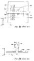
- the flexibility in the perpendicular axisis used to precisely control the high-precision z-axis position in the mid-web section and isolate this positional control from that exerted in the lower precision up-web and down-web sections.
- the mediais free to flex in the z-direction in the transition zones between the up-web and mid-web sections and between the mid-web and down-web sections, hence dramatically reducing the sensitivity of the z-axis behavior of the media in the precision zone to conditions outside the precision zone.
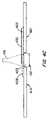
- the vertical cross section of the media transition between sections and the relative thicknesses of the air gapsare schematically illustrated in FIG. 4C .
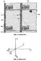
- the vacuumis introduced to the vacuum nozzles or ports by means of a trench extending across the granite base.
- the trenchreduces the plumbing complexity and also acts as a plenum chamber equalizing the negative pressure (vacuum) for all the vacuum ports.
- the distribution of vacuum nozzles within pads as well as adjustment of the vacuum/compressed gas pressuresis used to optimize the air cushion uniformity and obtain an air cushion of the desired thickness.
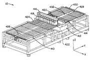
- the granite base and gantryserve as a reference for assembly of the entire stage system: Its top surface provides a precision reference surface for mounting the y-axis guides and linear motors; the front and back surfaces are equipped with specialized mounting hardware enabling precise positioning of the up-web and down-web air tables. Since the mass of the actuated media is much smaller than the mass of the rigid chuck, the gantry assembly may be considerably lighter than those in conventional stage designs. However, the gantry assembly is typically at least an order of magnitude heavier than the payloads installed on the gantry. This helps to balance out and dissipate the reaction forces generated by acceleration and/or deceleration of the payloads.
Landscapes
- Physics & Mathematics (AREA)
- Engineering & Computer Science (AREA)
- General Physics & Mathematics (AREA)
- Life Sciences & Earth Sciences (AREA)
- Chemical & Material Sciences (AREA)
- Biochemistry (AREA)
- Immunology (AREA)
- Pathology (AREA)
- General Health & Medical Sciences (AREA)
- Analytical Chemistry (AREA)
- Health & Medical Sciences (AREA)
- Textile Engineering (AREA)
- Microelectronics & Electronic Packaging (AREA)
- Nonlinear Science (AREA)
- Optics & Photonics (AREA)
- Crystallography & Structural Chemistry (AREA)
- Power Engineering (AREA)
- Computer Hardware Design (AREA)
- Manufacturing & Machinery (AREA)
- Condensed Matter Physics & Semiconductors (AREA)
- Mining & Mineral Resources (AREA)
- Mathematical Physics (AREA)
- Civil Engineering (AREA)
- General Life Sciences & Earth Sciences (AREA)
- Paleontology (AREA)
- Environmental Sciences (AREA)
- General Engineering & Computer Science (AREA)
- Structural Engineering (AREA)
- Soil Sciences (AREA)
- Container, Conveyance, Adherence, Positioning, Of Wafer (AREA)
- Liquid Crystal (AREA)
- Length Measuring Devices With Unspecified Measuring Means (AREA)
- Magnetic Bearings And Hydrostatic Bearings (AREA)
Abstract
Description
Tseq=Tload+Tmove
the pipelined operation has a reduced tact time of
Tpipe=Tmove
- Three welded steel base frames for up-
web 810,mid-web 812 and down-web 814 sections; - Gantry sub-assembly with
granite base 816; - Two y-axis linear servo motor assemblies (up-
web 818 and down-web820) with vacuum contacts; - Two air tables (up-
web 822, down-web824). The size of the down-web air table is determined by the plant layout and the mode of operation (robot loading/unloading versus in-line operation)
- Three welded steel base frames for up-
Claims (11)
Priority Applications (1)
| Application Number | Priority Date | Filing Date | Title |
|---|---|---|---|
| US11/249,039US7137309B2 (en) | 2003-08-08 | 2005-10-11 | High precision gas bearing split-axis stage for transport and constraint of large flat flexible media during processing |
Applications Claiming Priority (2)
| Application Number | Priority Date | Filing Date | Title |
|---|---|---|---|
| US10/637,215US7077019B2 (en) | 2003-08-08 | 2003-08-08 | High precision gas bearing split-axis stage for transport and constraint of large flat flexible media during processing |
| US11/249,039US7137309B2 (en) | 2003-08-08 | 2005-10-11 | High precision gas bearing split-axis stage for transport and constraint of large flat flexible media during processing |
Related Parent Applications (1)
| Application Number | Title | Priority Date | Filing Date |
|---|---|---|---|
| US10/637,215DivisionUS7077019B2 (en) | 2003-08-08 | 2003-08-08 | High precision gas bearing split-axis stage for transport and constraint of large flat flexible media during processing |
Publications (2)
| Publication Number | Publication Date |
|---|---|
| US20060096395A1 US20060096395A1 (en) | 2006-05-11 |
| US7137309B2true US7137309B2 (en) | 2006-11-21 |
Family
ID=34193566
Family Applications (2)
| Application Number | Title | Priority Date | Filing Date |
|---|---|---|---|
| US10/637,215Expired - LifetimeUS7077019B2 (en) | 2003-08-08 | 2003-08-08 | High precision gas bearing split-axis stage for transport and constraint of large flat flexible media during processing |
| US11/249,039Expired - LifetimeUS7137309B2 (en) | 2003-08-08 | 2005-10-11 | High precision gas bearing split-axis stage for transport and constraint of large flat flexible media during processing |
Family Applications Before (1)
| Application Number | Title | Priority Date | Filing Date |
|---|---|---|---|
| US10/637,215Expired - LifetimeUS7077019B2 (en) | 2003-08-08 | 2003-08-08 | High precision gas bearing split-axis stage for transport and constraint of large flat flexible media during processing |
Country Status (5)
| Country | Link |
|---|---|
| US (2) | US7077019B2 (en) |
| JP (1) | JP4723201B2 (en) |
| KR (2) | KR20050018571A (en) |
| CN (2) | CN100445808C (en) |
| TW (1) | TWI324978B (en) |
Cited By (15)
| Publication number | Priority date | Publication date | Assignee | Title |
|---|---|---|---|---|
| US20050179453A1 (en)* | 2004-02-12 | 2005-08-18 | Shinichi Kurita | Integrated substrate transfer module |
| US20070216428A1 (en)* | 2006-03-14 | 2007-09-20 | Ralf Schmid | Method to reduce cross talk in a multi column e-beam test system |
| US7319335B2 (en) | 2004-02-12 | 2008-01-15 | Applied Materials, Inc. | Configurable prober for TFT LCD array testing |
| US7355418B2 (en) | 2004-02-12 | 2008-04-08 | Applied Materials, Inc. | Configurable prober for TFT LCD array test |
| US7535238B2 (en) | 2005-04-29 | 2009-05-19 | Applied Materials, Inc. | In-line electron beam test system |
| US7602199B2 (en) | 2006-05-31 | 2009-10-13 | Applied Materials, Inc. | Mini-prober for TFT-LCD testing |
| US20090290960A1 (en)* | 2008-05-20 | 2009-11-26 | Nfjv, Llc | Apparatus for moving and securing a substrate |
| US7786742B2 (en) | 2006-05-31 | 2010-08-31 | Applied Materials, Inc. | Prober for electronic device testing on large area substrates |
| US20100314224A1 (en)* | 2008-04-07 | 2010-12-16 | Asyst Technologies, Inc. | Segmented material conveyor system, threshold assembly and method for making and using the same |
| US20120009051A1 (en)* | 2009-01-02 | 2012-01-12 | Edgar Ruth | Method and device for aligning substrates |
| US20130067956A1 (en)* | 2011-08-24 | 2013-03-21 | Richard Hagan | Apparatus and method for characterizing glass sheets |
| US9035673B2 (en) | 2010-01-25 | 2015-05-19 | Palo Alto Research Center Incorporated | Method of in-process intralayer yield detection, interlayer shunt detection and correction |
| US10613020B2 (en)* | 2017-08-10 | 2020-04-07 | The Boeing Company | Burr detection systems and methods |
| CN111747079A (en)* | 2019-03-28 | 2020-10-09 | Hb技术有限公司 | Hybrid display panel inspection device capable of aligning theta axis of original plate and separation plate |
| WO2022144715A1 (en)* | 2020-12-29 | 2022-07-07 | Photon Dynamics, Inc. | Synchronous substrate transport and electrical probing |
Families Citing this family (78)
| Publication number | Priority date | Publication date | Assignee | Title |
|---|---|---|---|---|
| JP4519705B2 (en)* | 2005-04-26 | 2010-08-04 | 株式会社堀場製作所 | Panel member inspection apparatus and position information correction program applied thereto |
| US20060273815A1 (en)* | 2005-06-06 | 2006-12-07 | Applied Materials, Inc. | Substrate support with integrated prober drive |
| US7543867B2 (en)* | 2005-09-30 | 2009-06-09 | Photon Dynamics, Inc. | Vacuum gripping system for positioning large thin substrates on a support table |
| JP4123271B2 (en)* | 2005-11-28 | 2008-07-23 | 船井電機株式会社 | LCD module brightness measuring device |
| US20070151296A1 (en)* | 2005-12-22 | 2007-07-05 | Photon Dynamics, Inc. | Method and apparatus for handling and aligning glass substrates |
| KR101166828B1 (en)* | 2005-12-29 | 2012-07-19 | 엘지디스플레이 주식회사 | Apparatus for Testing flat panel display device and testing method thereof |
| KR100765124B1 (en) | 2006-02-14 | 2007-10-11 | 주식회사 엔씨비네트웍스 | Glass Carrier |
| DE102006009639A1 (en)* | 2006-03-02 | 2007-09-06 | Schott Ag | Vacuum clamping plate |
| JP5027108B2 (en)* | 2006-03-06 | 2012-09-19 | 株式会社アルバック | Stage equipment |
| JP2007281285A (en)* | 2006-04-10 | 2007-10-25 | Olympus Corp | Substrate transport apparatus |
| TW200821247A (en)* | 2006-09-22 | 2008-05-16 | Olympus Corp | Substrate inspecting apparatus |
| US20080251019A1 (en)* | 2007-04-12 | 2008-10-16 | Sriram Krishnaswami | System and method for transferring a substrate into and out of a reduced volume chamber accommodating multiple substrates |
| JP2009085865A (en)* | 2007-10-02 | 2009-04-23 | Olympus Corp | Substrate inspection device |
| JP2011519796A (en) | 2008-03-11 | 2011-07-14 | コアフロー リミテッド | Method and system for locally controlling the support of a flat object |
| US9048344B2 (en) | 2008-06-13 | 2015-06-02 | Kateeva, Inc. | Gas enclosure assembly and system |
| US12018857B2 (en) | 2008-06-13 | 2024-06-25 | Kateeva, Inc. | Gas enclosure assembly and system |
| US8383202B2 (en) | 2008-06-13 | 2013-02-26 | Kateeva, Inc. | Method and apparatus for load-locked printing |
| US10442226B2 (en) | 2008-06-13 | 2019-10-15 | Kateeva, Inc. | Gas enclosure assembly and system |
| US11975546B2 (en) | 2008-06-13 | 2024-05-07 | Kateeva, Inc. | Gas enclosure assembly and system |
| US12064979B2 (en) | 2008-06-13 | 2024-08-20 | Kateeva, Inc. | Low-particle gas enclosure systems and methods |
| US10434804B2 (en) | 2008-06-13 | 2019-10-08 | Kateeva, Inc. | Low particle gas enclosure systems and methods |
| US9604245B2 (en) | 2008-06-13 | 2017-03-28 | Kateeva, Inc. | Gas enclosure systems and methods utilizing an auxiliary enclosure |
| US8899171B2 (en) | 2008-06-13 | 2014-12-02 | Kateeva, Inc. | Gas enclosure assembly and system |
| JP4585018B2 (en)* | 2008-08-04 | 2010-11-24 | 住友重機械工業株式会社 | Stage equipment |
| JP4964853B2 (en)* | 2008-09-24 | 2012-07-04 | 住友重機械工業株式会社 | Stage equipment |
| US8047354B2 (en) | 2008-09-26 | 2011-11-01 | Corning Incorporated | Liquid-ejecting bearings for transport of glass sheets |
| US8511461B2 (en)* | 2008-11-25 | 2013-08-20 | Corning Incorporated | Gas-ejecting bearings for transport of glass sheets |
| DE102009013353B3 (en)* | 2009-03-16 | 2010-10-07 | Siemens Aktiengesellschaft | Method for determining armor for constant tables of placement machines |
| TWI472467B (en)* | 2009-04-23 | 2015-02-11 | Corning Inc | Liquid-ejecting bearings for transport of glass sheets |
| US20110053092A1 (en)* | 2009-08-20 | 2011-03-03 | Nikon Corporation | Object processing apparatus, exposure apparatus and exposure method, and device manufacturing method |
| US20110042874A1 (en)* | 2009-08-20 | 2011-02-24 | Nikon Corporation | Object processing apparatus, exposure apparatus and exposure method, and device manufacturing method |
| US8699001B2 (en)* | 2009-08-20 | 2014-04-15 | Nikon Corporation | Object moving apparatus, object processing apparatus, exposure apparatus, object inspecting apparatus and device manufacturing method |
| KR101144958B1 (en)* | 2009-09-14 | 2012-05-11 | 순환엔지니어링 주식회사 | Gantry stage orthogonality error measurement and compensation method on homing processing |
| JP5380225B2 (en)* | 2009-09-24 | 2014-01-08 | 株式会社日立ハイテクノロジーズ | Glass substrate inspection equipment |
| US8598538B2 (en)* | 2010-09-07 | 2013-12-03 | Nikon Corporation | Movable body apparatus, object processing device, exposure apparatus, flat-panel display manufacturing method, and device manufacturing method |
| US8502967B2 (en)* | 2011-02-01 | 2013-08-06 | Cooper S. K. Kuo | Apparatus for optical inspection |
| TW201304905A (en)* | 2011-07-29 | 2013-02-01 | Sparking Power Technology Co Ltd | Vertical machine center with floating workbench |
| CN106299116B (en) | 2011-08-09 | 2019-07-12 | 科迪华公司 | Printing device and method downwards |
| US9120344B2 (en) | 2011-08-09 | 2015-09-01 | Kateeva, Inc. | Apparatus and method for control of print gap |
| CN102514877B (en)* | 2011-12-01 | 2015-01-28 | 珠海全宝电子科技有限公司 | Automatic metal substrate feeding device |
| JP5776940B2 (en)* | 2012-01-25 | 2015-09-09 | 日本電気硝子株式会社 | Glass plate edge inspection equipment |
| SG11201501085TA (en)* | 2012-08-31 | 2015-04-29 | Semiconductor Tech & Instr Inc | Single ultra-planar wafer table structure for both wafers and film frames |
| US9389187B2 (en)* | 2012-11-29 | 2016-07-12 | Corning Incorporated | Glass-sheet optical inspection systems and methods with illumination and exposure control |
| US10468279B2 (en) | 2013-12-26 | 2019-11-05 | Kateeva, Inc. | Apparatus and techniques for thermal treatment of electronic devices |
| US9343678B2 (en)* | 2014-01-21 | 2016-05-17 | Kateeva, Inc. | Apparatus and techniques for electronic device encapsulation |
| KR102307190B1 (en)* | 2014-01-21 | 2021-09-30 | 카티바, 인크. | Apparatus and techniques for electronic device encapsulation |
| EP3882961B1 (en) | 2014-04-30 | 2023-07-26 | Kateeva, Inc. | Gas cushion apparatus and techniques for substrate coating |
| US12251946B2 (en) | 2014-06-17 | 2025-03-18 | Kateeva, Inc. | Printing system assemblies and methods |
| KR20240036141A (en) | 2014-06-17 | 2024-03-19 | 카티바, 인크. | Printing system assemblies and methods |
| US9567166B2 (en)* | 2014-10-10 | 2017-02-14 | Goodrich Corporation | Compact centrifugal air blowers for air cushion supported cargo loading platform |
| US9511860B2 (en)* | 2014-10-10 | 2016-12-06 | Goodrich Corporation | Air cushion aircraft cargo loading systems and wireless communication unit |
| US9511861B2 (en)* | 2014-10-10 | 2016-12-06 | Goodrich Corporation | Noise reduction barrier for air cushion supported aircraft cargo loading robot |
| US9555888B2 (en) | 2014-10-10 | 2017-01-31 | Goodrich Corporation | Pressure compensating air curtain for air cushion supported cargo loading platform |
| US10196146B2 (en) | 2014-10-10 | 2019-02-05 | Goodrich Corporation | Self propelled air cushion supported aircraft cargo loading systems and methods |
| WO2016086192A1 (en) | 2014-11-26 | 2016-06-02 | Kateeva, Inc. | Environmentally controlled coating systems |
| US10393225B2 (en) | 2015-01-05 | 2019-08-27 | Goodrich Corporation | Integrated multi-function propulsion belt for air cushion supported aircraft cargo loading robot |
| US10752449B2 (en)* | 2015-03-30 | 2020-08-25 | Nikon Corporation | Object carrier device, exposure apparatus, manufacturing method of flat-panel display, device manufacturing method, object carrying method, and exposure method |
| CN105651163A (en)* | 2015-12-28 | 2016-06-08 | 威申精密仪器(上海)有限公司 | Image measuring instrument with high measurement precision |
| EP3479173A1 (en)* | 2016-07-01 | 2019-05-08 | ASML Netherlands B.V. | Stage system, lithographic apparatus, method for positioning and device manufacturing method |
| US9961782B2 (en) | 2016-07-08 | 2018-05-01 | Kateeva, Inc. | Transport path correction techniques and related systems, methods and devices |
| JP6347285B2 (en)* | 2016-11-04 | 2018-06-27 | 株式会社ニコン | Object processing apparatus, exposure apparatus, exposure method, and device manufacturing method |
| CN106814479B (en)* | 2017-01-11 | 2019-07-16 | 昆山国显光电有限公司 | A kind of offset compensating method of panel defect location, apparatus and system |
| CN106829475A (en)* | 2017-02-20 | 2017-06-13 | 东旭科技集团有限公司 | Glass substrate transmission equipment |
| US9889995B1 (en)* | 2017-03-15 | 2018-02-13 | Core Flow Ltd. | Noncontact support platform with blockage detection |
| JP7106627B2 (en) | 2017-07-11 | 2022-07-26 | コーニング インコーポレイテッド | Apparatus and method for processing glass |
| JP2019042694A (en)* | 2017-09-05 | 2019-03-22 | シャープ株式会社 | Substrate processing equipment |
| CN108115631B (en)* | 2017-12-20 | 2020-04-14 | 重庆家本家科技有限公司 | Computer maintenance special workbench |
| JP7089737B2 (en)* | 2018-03-30 | 2022-06-23 | 株式会社フジワーク | Sheet thickness measuring device |
| JP6631655B2 (en)* | 2018-05-25 | 2020-01-15 | 株式会社ニコン | Exposure apparatus, flat panel display manufacturing method, and device manufacturing method |
| CN108680113B (en)* | 2018-07-19 | 2024-05-07 | 杭州愚工智能设备有限公司 | Full-automatic glass detection and sheet arrangement production system and working method thereof |
| CN109668831B (en)* | 2019-01-24 | 2021-04-02 | 合肥工业大学 | A circular belt transmission device for an automatic optical detection instrument for defects in a liquid crystal display |
| EP3719443B1 (en) | 2019-04-03 | 2021-06-09 | Hexagon Technology Center GmbH | Coordinate-measuring machine with self-cleaning air bearing |
| CN110514673A (en)* | 2019-06-28 | 2019-11-29 | 苏州精濑光电有限公司 | A kind of detection device of glass substrate |
| CN110346378B (en)* | 2019-07-24 | 2024-05-14 | 浙江欧视电科技有限公司 | Full-automatic AOI check out test set |
| CN113008794B (en)* | 2021-03-02 | 2022-05-17 | 苏州天准科技股份有限公司 | Detection equipment and optical detection method |
| CN113008537A (en)* | 2021-03-02 | 2021-06-22 | 苏州天准科技股份有限公司 | Damping rack and detection equipment adopting same |
| CN113335589B (en)* | 2021-05-10 | 2022-07-29 | 山西光兴光电科技有限公司 | A-shaped frame position correction detection device and glass packaging system |
| KR102620963B1 (en)* | 2021-08-26 | 2024-01-04 | (주)케파 | Surface Microfault Detection System |
Citations (27)
| Publication number | Priority date | Publication date | Assignee | Title |
|---|---|---|---|---|
| US4534695A (en)* | 1983-05-23 | 1985-08-13 | Eaton Corporation | Wafer transport system |
| US4730526A (en) | 1985-09-05 | 1988-03-15 | Gerber Garment Technology | Conveyorized vacuum table for feeding sheet material |
| US5016363A (en) | 1987-05-09 | 1991-05-21 | Kurt Krieger | Device for float-conveying of webs of material |
| US5056765A (en) | 1989-06-06 | 1991-10-15 | Orbot Systems, Ltd. | Immobilizing device particularly useful during processing or testing flat workpieces |
| US5141212A (en) | 1991-04-08 | 1992-08-25 | Ekstrom Carlson & Co. | Vacuum chuck with foam workpiece-supporting surface |
| US5290134A (en)* | 1991-12-03 | 1994-03-01 | Advantest Corporation | Pick and place for automatic test handler |
| US5307011A (en)* | 1991-12-04 | 1994-04-26 | Advantest Corporation | Loader and unloader for test handler |
| US5374021A (en) | 1992-11-27 | 1994-12-20 | Orbotech Ltd. | Vacuum holder particulary useful as a vacuum table |
| US5384531A (en)* | 1991-09-05 | 1995-01-24 | Mitsubishi Electrical Engineering Co. Ltd. | Apparatus for inspecting characteristics of semiconductor chips |
| US5701178A (en)* | 1994-07-05 | 1997-12-23 | Corning Incorporated | Non-damaging flatness and thickness gauge for glass |
| US5797317A (en) | 1996-09-06 | 1998-08-25 | Orbot Instruments Ltd. | Universal chuck for holding plates of various sizes |
| US5913268A (en) | 1998-02-17 | 1999-06-22 | Xerox Corporation | Pneumatic rollers and paper handling arrangements |
| US6145648A (en) | 1997-01-24 | 2000-11-14 | Orbotech Ltd. | Method and system for continuously processing successive workpieces along a production line |
| US6217272B1 (en)* | 1998-10-01 | 2001-04-17 | Applied Science And Technology, Inc. | In-line sputter deposition system |
| US6223880B1 (en) | 1996-02-23 | 2001-05-01 | Orbotech Ltd. | Conveyor table having selectively enabled conveyor elements |
| US6281655B1 (en)* | 1999-12-23 | 2001-08-28 | Nikon Corporation | High performance stage assembly |
| US6442369B1 (en) | 2000-11-27 | 2002-08-27 | Xerox Corporation | Air bearing mechanism for flattening paper in a printing machine |
| JP2002267571A (en)* | 2001-03-06 | 2002-09-18 | Sharp Corp | Optical property inspection device |
| KR100358704B1 (en)* | 2001-02-05 | 2002-10-31 | 메카텍스 (주) | Panel Supplying Apparatus of Liquid Crystal Display Panel System |
| KR100358707B1 (en)* | 2001-02-05 | 2002-10-31 | 메카텍스 (주) | Panel Sending Apparatus of Liquid Crystal Display Inspection System |
| US6486927B1 (en) | 1999-11-19 | 2002-11-26 | De & T Co., Ltd. | Liquid crystal display test system |
| US6486941B1 (en)* | 2000-04-24 | 2002-11-26 | Nikon Corporation | Guideless stage |
| JP2002365026A (en)* | 2001-06-07 | 2002-12-18 | Sigma Technos Kk | Substrate inspection apparatus |
| US6675666B2 (en)* | 2000-09-06 | 2004-01-13 | Olympus Optical Co., Ltd. | Substrate transportation apparatus |
| US20040028113A1 (en)* | 2000-08-25 | 2004-02-12 | Photon Dynamics, Inc. | Method and apparatus for detection of defects using thermal stimulation |
| US20040086166A1 (en)* | 2002-11-01 | 2004-05-06 | Photon Dynamics, Inc. | Method and apparatus for flat patterned media inspection |
| US6906546B2 (en)* | 2002-10-29 | 2005-06-14 | Nec Corporation | Semiconductor device inspection apparatus and inspection method |
Family Cites Families (9)
| Publication number | Priority date | Publication date | Assignee | Title |
|---|---|---|---|---|
| FR2028687B1 (en)* | 1969-01-22 | 1974-02-01 | Saint Gobain Pont A Mousson | |
| CA931024A (en)* | 1970-12-19 | 1973-07-31 | H. Prange Bernard | Method and apparatus for silk screening a pattern on an underlying substrate |
| JPS63265129A (en)* | 1987-04-23 | 1988-11-01 | Sharp Corp | Display device pixel inspection system |
| US5015363A (en)* | 1987-11-06 | 1991-05-14 | Uop | FCC stripping method |
| IT224807Z2 (en)* | 1991-09-20 | 1996-06-27 | Emm Srl | ELECTROMECHANICAL DEVICE FOR THE SELECTION OF DRIVING PLATES IN WORK OF THE NEEDLES OF AN AUTOMATIC RECTILINEE MACHINE FOR KNITWEAR |
| TW459109B (en)* | 1995-06-14 | 2001-10-11 | Burckhardt Ag Maschf | Sealing ring |
| JPH0933589A (en)* | 1995-07-14 | 1997-02-07 | Tokyo Electron Ltd | Inspection instrument |
| KR20010030575A (en)* | 1998-07-28 | 2001-04-16 | 이마이 기요스케 | Inspection system for inspecting discrete wiring patterns formed on a continuous substrate sheet of a flexible material |
| TWI222423B (en)* | 2001-12-27 | 2004-10-21 | Orbotech Ltd | System and methods for conveying and transporting levitated articles |
- 2003
- 2003-08-08USUS10/637,215patent/US7077019B2/ennot_activeExpired - Lifetime
- 2004
- 2004-03-25TWTW093108091Apatent/TWI324978B/ennot_activeIP Right Cessation
- 2004-03-30KRKR1020040021690Apatent/KR20050018571A/ennot_activeCeased
- 2004-03-31CNCNB2004100307340Apatent/CN100445808C/ennot_activeExpired - Lifetime
- 2004-03-31CNCN2008101711791Apatent/CN101441337B/ennot_activeExpired - Lifetime
- 2004-03-31JPJP2004106363Apatent/JP4723201B2/ennot_activeExpired - Lifetime
- 2005
- 2005-10-11USUS11/249,039patent/US7137309B2/ennot_activeExpired - Lifetime
- 2012
- 2012-01-27KRKR1020120008559Apatent/KR101344869B1/ennot_activeExpired - Lifetime
Patent Citations (29)
| Publication number | Priority date | Publication date | Assignee | Title |
|---|---|---|---|---|
| US4534695A (en)* | 1983-05-23 | 1985-08-13 | Eaton Corporation | Wafer transport system |
| US4730526A (en) | 1985-09-05 | 1988-03-15 | Gerber Garment Technology | Conveyorized vacuum table for feeding sheet material |
| US5016363A (en) | 1987-05-09 | 1991-05-21 | Kurt Krieger | Device for float-conveying of webs of material |
| US5056765A (en) | 1989-06-06 | 1991-10-15 | Orbot Systems, Ltd. | Immobilizing device particularly useful during processing or testing flat workpieces |
| US5141212A (en) | 1991-04-08 | 1992-08-25 | Ekstrom Carlson & Co. | Vacuum chuck with foam workpiece-supporting surface |
| US5384531A (en)* | 1991-09-05 | 1995-01-24 | Mitsubishi Electrical Engineering Co. Ltd. | Apparatus for inspecting characteristics of semiconductor chips |
| US5290134A (en)* | 1991-12-03 | 1994-03-01 | Advantest Corporation | Pick and place for automatic test handler |
| US5307011A (en)* | 1991-12-04 | 1994-04-26 | Advantest Corporation | Loader and unloader for test handler |
| US5374021A (en) | 1992-11-27 | 1994-12-20 | Orbotech Ltd. | Vacuum holder particulary useful as a vacuum table |
| US5701178A (en)* | 1994-07-05 | 1997-12-23 | Corning Incorporated | Non-damaging flatness and thickness gauge for glass |
| US6223880B1 (en) | 1996-02-23 | 2001-05-01 | Orbotech Ltd. | Conveyor table having selectively enabled conveyor elements |
| US6367609B2 (en) | 1996-02-23 | 2002-04-09 | Orbotech Ltd. | Conveyor apparatus |
| US5797317A (en) | 1996-09-06 | 1998-08-25 | Orbot Instruments Ltd. | Universal chuck for holding plates of various sizes |
| US6145648A (en) | 1997-01-24 | 2000-11-14 | Orbotech Ltd. | Method and system for continuously processing successive workpieces along a production line |
| US5913268A (en) | 1998-02-17 | 1999-06-22 | Xerox Corporation | Pneumatic rollers and paper handling arrangements |
| US6217272B1 (en)* | 1998-10-01 | 2001-04-17 | Applied Science And Technology, Inc. | In-line sputter deposition system |
| US6486927B1 (en) | 1999-11-19 | 2002-11-26 | De & T Co., Ltd. | Liquid crystal display test system |
| US6281655B1 (en)* | 1999-12-23 | 2001-08-28 | Nikon Corporation | High performance stage assembly |
| US6486941B1 (en)* | 2000-04-24 | 2002-11-26 | Nikon Corporation | Guideless stage |
| US20040028113A1 (en)* | 2000-08-25 | 2004-02-12 | Photon Dynamics, Inc. | Method and apparatus for detection of defects using thermal stimulation |
| US6675666B2 (en)* | 2000-09-06 | 2004-01-13 | Olympus Optical Co., Ltd. | Substrate transportation apparatus |
| US6442369B1 (en) | 2000-11-27 | 2002-08-27 | Xerox Corporation | Air bearing mechanism for flattening paper in a printing machine |
| KR100358704B1 (en)* | 2001-02-05 | 2002-10-31 | 메카텍스 (주) | Panel Supplying Apparatus of Liquid Crystal Display Panel System |
| KR100358707B1 (en)* | 2001-02-05 | 2002-10-31 | 메카텍스 (주) | Panel Sending Apparatus of Liquid Crystal Display Inspection System |
| JP2002267571A (en)* | 2001-03-06 | 2002-09-18 | Sharp Corp | Optical property inspection device |
| JP2002365026A (en)* | 2001-06-07 | 2002-12-18 | Sigma Technos Kk | Substrate inspection apparatus |
| US6906546B2 (en)* | 2002-10-29 | 2005-06-14 | Nec Corporation | Semiconductor device inspection apparatus and inspection method |
| US20040086166A1 (en)* | 2002-11-01 | 2004-05-06 | Photon Dynamics, Inc. | Method and apparatus for flat patterned media inspection |
| US20040109598A1 (en)* | 2002-11-01 | 2004-06-10 | Photon Dynamics, Inc. | Method and apparatus for flat patterned media inspection |
Non-Patent Citations (2)
| Title |
|---|
| "Arraychecker 3000" to PhotonDynamics, available on the Internet at <http://www.photondynamics.com>.* |
| "Arraychecker 3500" to PhotonDynamics, available on the Internet at <http://www.photondynamics.com>.* |
Cited By (28)
| Publication number | Priority date | Publication date | Assignee | Title |
|---|---|---|---|---|
| US20050179453A1 (en)* | 2004-02-12 | 2005-08-18 | Shinichi Kurita | Integrated substrate transfer module |
| US7919972B2 (en) | 2004-02-12 | 2011-04-05 | Applied Materials, Inc. | Integrated substrate transfer module |
| US7319335B2 (en) | 2004-02-12 | 2008-01-15 | Applied Materials, Inc. | Configurable prober for TFT LCD array testing |
| US7330021B2 (en) | 2004-02-12 | 2008-02-12 | Applied Materials, Inc. | Integrated substrate transfer module |
| US7355418B2 (en) | 2004-02-12 | 2008-04-08 | Applied Materials, Inc. | Configurable prober for TFT LCD array test |
| US7847566B2 (en) | 2004-02-12 | 2010-12-07 | Applied Materials, Inc. | Configurable prober for TFT LCD array test |
| US7746088B2 (en) | 2005-04-29 | 2010-06-29 | Applied Materials, Inc. | In-line electron beam test system |
| US7535238B2 (en) | 2005-04-29 | 2009-05-19 | Applied Materials, Inc. | In-line electron beam test system |
| US7569818B2 (en) | 2006-03-14 | 2009-08-04 | Applied Materials, Inc. | Method to reduce cross talk in a multi column e-beam test system |
| US20070216428A1 (en)* | 2006-03-14 | 2007-09-20 | Ralf Schmid | Method to reduce cross talk in a multi column e-beam test system |
| US7602199B2 (en) | 2006-05-31 | 2009-10-13 | Applied Materials, Inc. | Mini-prober for TFT-LCD testing |
| US7786742B2 (en) | 2006-05-31 | 2010-08-31 | Applied Materials, Inc. | Prober for electronic device testing on large area substrates |
| US8096408B2 (en)* | 2008-04-07 | 2012-01-17 | Muratec Automation Co., Ltd. | Segmented material conveyor system, threshold assembly and method for making and using the same |
| US20100314224A1 (en)* | 2008-04-07 | 2010-12-16 | Asyst Technologies, Inc. | Segmented material conveyor system, threshold assembly and method for making and using the same |
| US7976261B2 (en) | 2008-05-20 | 2011-07-12 | Fas Holdings Group, Llc | Apparatus for moving and securing a substrate |
| US20090290960A1 (en)* | 2008-05-20 | 2009-11-26 | Nfjv, Llc | Apparatus for moving and securing a substrate |
| US8523510B2 (en) | 2008-05-20 | 2013-09-03 | Fas Holdings Group, Llc | Method for moving and securing a substrate |
| US8961094B2 (en)* | 2009-01-02 | 2015-02-24 | Singulus Technologies Ag | Method and device for aligning substrates |
| US20120009051A1 (en)* | 2009-01-02 | 2012-01-12 | Edgar Ruth | Method and device for aligning substrates |
| US9035673B2 (en) | 2010-01-25 | 2015-05-19 | Palo Alto Research Center Incorporated | Method of in-process intralayer yield detection, interlayer shunt detection and correction |
| US8773656B2 (en)* | 2011-08-24 | 2014-07-08 | Corning Incorporated | Apparatus and method for characterizing glass sheets |
| US20130067956A1 (en)* | 2011-08-24 | 2013-03-21 | Richard Hagan | Apparatus and method for characterizing glass sheets |
| US9090412B2 (en) | 2011-08-24 | 2015-07-28 | Corning Incorporated | Apparatus and method for characterizing glass sheets |
| US10613020B2 (en)* | 2017-08-10 | 2020-04-07 | The Boeing Company | Burr detection systems and methods |
| CN111747079A (en)* | 2019-03-28 | 2020-10-09 | Hb技术有限公司 | Hybrid display panel inspection device capable of aligning theta axis of original plate and separation plate |
| CN111747079B (en)* | 2019-03-28 | 2022-05-13 | Hb技术有限公司 | Hybrid display panel inspection device capable of aligning theta axis of original plate and separation plate |
| WO2022144715A1 (en)* | 2020-12-29 | 2022-07-07 | Photon Dynamics, Inc. | Synchronous substrate transport and electrical probing |
| US20240112935A1 (en)* | 2020-12-29 | 2024-04-04 | Photon Dynamics, Inc. | Synchronous substrate transport and electrical probing |
Also Published As
| Publication number | Publication date |
|---|---|
| TWI324978B (en) | 2010-05-21 |
| CN101441337A (en) | 2009-05-27 |
| US20060096395A1 (en) | 2006-05-11 |
| JP2005062819A (en) | 2005-03-10 |
| KR20120024904A (en) | 2012-03-14 |
| TW200508124A (en) | 2005-03-01 |
| KR101344869B1 (en) | 2013-12-24 |
| US20050040338A1 (en) | 2005-02-24 |
| KR20050018571A (en) | 2005-02-23 |
| CN101441337B (en) | 2012-05-23 |
| CN1580875A (en) | 2005-02-16 |
| CN100445808C (en) | 2008-12-24 |
| JP4723201B2 (en) | 2011-07-13 |
| US7077019B2 (en) | 2006-07-18 |
Similar Documents
| Publication | Publication Date | Title |
|---|---|---|
| US7137309B2 (en) | High precision gas bearing split-axis stage for transport and constraint of large flat flexible media during processing | |
| US7468611B2 (en) | Continuous linear scanning of large flat panel media | |
| USRE40043E1 (en) | Positioning device having two object holders | |
| KR100803046B1 (en) | Vision inspection system and inspection method of inspected object using the same | |
| JP2005132626A (en) | Conveying apparatus, application system and inspection system | |
| CN101144920B (en) | Substrate detecting device | |
| WO2008035752A1 (en) | Substrate inspecting apparatus | |
| JP2004334220A (en) | Integrated large glass handling system | |
| JP2006266722A (en) | System and method for inspecting substrate | |
| JP2002365026A (en) | Substrate inspection apparatus | |
| JP4449299B2 (en) | Substrate holder, substrate tray, stage device, exposure device | |
| US8488105B2 (en) | Multi-table lithographic systems, lithography processing tools and methods for processing workpieces | |
| JPH11227943A (en) | Substrate transfer device | |
| JP2004238133A (en) | Thin plate holding device, thin plate transport device and thin plate inspection device | |
| KR102274053B1 (en) | Apparatus for Reviewing and Inspecting Panel for Rapid Inspection | |
| JPH10123193A (en) | Display panel substrate inspection apparatus and inspection method | |
| JP3195623U (en) | High precision gripper for thin plate operation and inspection apparatus including the same | |
| CN120195191A (en) | Glass substrate defect detection equipment | |
| JP2007142293A (en) | Board inspection equipment | |
| JP2009214106A (en) | Conveying apparatus, application system and inspection system | |
| JP2009105439A (en) | Board inspection equipment | |
| JP2008157691A (en) | Image display panel inspection jig, image display panel inspection apparatus, and image display panel inspection method |
Legal Events
| Date | Code | Title | Description |
|---|---|---|---|
| STCF | Information on status: patent grant | Free format text:PATENTED CASE | |
| FEPP | Fee payment procedure | Free format text:PAT HOLDER NO LONGER CLAIMS SMALL ENTITY STATUS, ENTITY STATUS SET TO UNDISCOUNTED (ORIGINAL EVENT CODE: STOL); ENTITY STATUS OF PATENT OWNER: LARGE ENTITY | |
| FPAY | Fee payment | Year of fee payment:4 | |
| FPAY | Fee payment | Year of fee payment:8 | |
| AS | Assignment | Owner name:JPMORGAN CHASE BANK, N.A., AS ADMINISTRATIVE AGENT Free format text:SECURITY INTEREST;ASSIGNOR:PHOTON DYNAMICS, INC.;REEL/FRAME:033543/0631 Effective date:20140807 | |
| AS | Assignment | Owner name:PHOTON DYNAMICS, INC., CALIFORNIA Free format text:RELEASE BY SECURED PARTY;ASSIGNOR:JPMORGAN CHASE BANK, N.A.;REEL/FRAME:039076/0165 Effective date:20160623 | |
| MAFP | Maintenance fee payment | Free format text:PAYMENT OF MAINTENANCE FEE, 12TH YEAR, LARGE ENTITY (ORIGINAL EVENT CODE: M1553) Year of fee payment:12 | |
| AS | Assignment | Owner name:PHOTON DYNAMICS, INC., CALIFORNIA Free format text:ASSIGNMENT OF ASSIGNORS INTEREST;ASSIGNORS:WEISS, ADAM;SARANLI, AFSAR;GHELMAN, EDUARDO;AND OTHERS;REEL/FRAME:055266/0316 Effective date:20030807 | |
| AS | Assignment | Owner name:ORBOTECH LTD., ISRAEL Free format text:ASSIGNMENT OF ASSIGNORS INTEREST;ASSIGNOR:PHOTON DYNAMICS, INC.;REEL/FRAME:055831/0793 Effective date:20210326 |