US7137264B2 - Liquid galley refrigeration system for aircraft - Google Patents
Liquid galley refrigeration system for aircraftDownload PDFInfo
- Publication number
- US7137264B2 US7137264B2US11/081,446US8144605AUS7137264B2US 7137264 B2US7137264 B2US 7137264B2US 8144605 AUS8144605 AUS 8144605AUS 7137264 B2US7137264 B2US 7137264B2
- Authority
- US
- United States
- Prior art keywords
- working fluid
- galley
- food cart
- chiller
- recirculation pump
- Prior art date
- Legal status (The legal status is an assumption and is not a legal conclusion. Google has not performed a legal analysis and makes no representation as to the accuracy of the status listed.)
- Expired - Lifetime
Links
- 238000005057refrigerationMethods0.000titleabstractdescription34
- 239000007788liquidSubstances0.000titleabstractdescription15
- 239000012530fluidSubstances0.000claimsabstractdescription93
- 238000001816coolingMethods0.000claimsabstractdescription27
- 230000008859changeEffects0.000claimsabstractdescription5
- 239000012071phaseSubstances0.000claimsabstractdescription5
- 239000007791liquid phaseSubstances0.000claimsabstractdescription4
- 230000008602contractionEffects0.000claimsdescription3
- 238000007664blowingMethods0.000claims4
- 238000012546transferMethods0.000abstractdescription6
- 230000001105regulatory effectEffects0.000abstractdescription3
- 230000000694effectsEffects0.000abstractdescription2
- 239000003570airSubstances0.000description37
- 238000010586diagramMethods0.000description11
- 238000012544monitoring processMethods0.000description11
- 238000012806monitoring deviceMethods0.000description7
- 239000003507refrigerantSubstances0.000description7
- 230000001276controlling effectEffects0.000description6
- 238000000034methodMethods0.000description4
- 239000012080ambient airSubstances0.000description3
- 239000013529heat transfer fluidSubstances0.000description3
- 230000008569processEffects0.000description3
- 238000012423maintenanceMethods0.000description2
- 239000000463materialSubstances0.000description2
- 230000000704physical effectEffects0.000description2
- LVGUZGTVOIAKKC-UHFFFAOYSA-N1,1,1,2-tetrafluoroethaneChemical compoundFCC(F)(F)FLVGUZGTVOIAKKC-UHFFFAOYSA-N0.000description1
- 238000010521absorption reactionMethods0.000description1
- 238000013461designMethods0.000description1
- 238000001514detection methodMethods0.000description1
- 230000007257malfunctionEffects0.000description1
- 238000012986modificationMethods0.000description1
- 230000004048modificationEffects0.000description1
- 231100000252nontoxicToxicity0.000description1
- 230000003000nontoxic effectEffects0.000description1
- 231100000956nontoxicityToxicity0.000description1
- 239000010702perfluoropolyetherSubstances0.000description1
- 238000001824photoionisation detectionMethods0.000description1
- 230000001629suppressionEffects0.000description1
- 238000013022ventingMethods0.000description1
Images


Classifications
- B—PERFORMING OPERATIONS; TRANSPORTING
- B64—AIRCRAFT; AVIATION; COSMONAUTICS
- B64D—EQUIPMENT FOR FITTING IN OR TO AIRCRAFT; FLIGHT SUITS; PARACHUTES; ARRANGEMENT OR MOUNTING OF POWER PLANTS OR PROPULSION TRANSMISSIONS IN AIRCRAFT
- B64D11/00—Passenger or crew accommodation; Flight-deck installations not otherwise provided for
- B64D11/0007—Devices specially adapted for food or beverage distribution services
- B—PERFORMING OPERATIONS; TRANSPORTING
- B64—AIRCRAFT; AVIATION; COSMONAUTICS
- B64D—EQUIPMENT FOR FITTING IN OR TO AIRCRAFT; FLIGHT SUITS; PARACHUTES; ARRANGEMENT OR MOUNTING OF POWER PLANTS OR PROPULSION TRANSMISSIONS IN AIRCRAFT
- B64D13/00—Arrangements or adaptations of air-treatment apparatus for aircraft crew or passengers, or freight space
- B64D13/06—Arrangements or adaptations of air-treatment apparatus for aircraft crew or passengers, or freight space the air being conditioned
- B—PERFORMING OPERATIONS; TRANSPORTING
- B64—AIRCRAFT; AVIATION; COSMONAUTICS
- B64D—EQUIPMENT FOR FITTING IN OR TO AIRCRAFT; FLIGHT SUITS; PARACHUTES; ARRANGEMENT OR MOUNTING OF POWER PLANTS OR PROPULSION TRANSMISSIONS IN AIRCRAFT
- B64D11/00—Passenger or crew accommodation; Flight-deck installations not otherwise provided for
- B64D11/04—Galleys
- F—MECHANICAL ENGINEERING; LIGHTING; HEATING; WEAPONS; BLASTING
- F25—REFRIGERATION OR COOLING; COMBINED HEATING AND REFRIGERATION SYSTEMS; HEAT PUMP SYSTEMS; MANUFACTURE OR STORAGE OF ICE; LIQUEFACTION SOLIDIFICATION OF GASES
- F25D—REFRIGERATORS; COLD ROOMS; ICE-BOXES; COOLING OR FREEZING APPARATUS NOT OTHERWISE PROVIDED FOR
- F25D11/00—Self-contained movable devices, e.g. domestic refrigerators
- F25D11/003—Transport containers
- F—MECHANICAL ENGINEERING; LIGHTING; HEATING; WEAPONS; BLASTING
- F25—REFRIGERATION OR COOLING; COMBINED HEATING AND REFRIGERATION SYSTEMS; HEAT PUMP SYSTEMS; MANUFACTURE OR STORAGE OF ICE; LIQUEFACTION SOLIDIFICATION OF GASES
- F25D—REFRIGERATORS; COLD ROOMS; ICE-BOXES; COOLING OR FREEZING APPARATUS NOT OTHERWISE PROVIDED FOR
- F25D15/00—Devices not covered by group F25D11/00 or F25D13/00, e.g. non-self-contained movable devices
- F—MECHANICAL ENGINEERING; LIGHTING; HEATING; WEAPONS; BLASTING
- F25—REFRIGERATION OR COOLING; COMBINED HEATING AND REFRIGERATION SYSTEMS; HEAT PUMP SYSTEMS; MANUFACTURE OR STORAGE OF ICE; LIQUEFACTION SOLIDIFICATION OF GASES
- F25D—REFRIGERATORS; COLD ROOMS; ICE-BOXES; COOLING OR FREEZING APPARATUS NOT OTHERWISE PROVIDED FOR
- F25D17/00—Arrangements for circulating cooling fluids; Arrangements for circulating gas, e.g. air, within refrigerated spaces
- F25D17/02—Arrangements for circulating cooling fluids; Arrangements for circulating gas, e.g. air, within refrigerated spaces for circulating liquids, e.g. brine
- B—PERFORMING OPERATIONS; TRANSPORTING
- B64—AIRCRAFT; AVIATION; COSMONAUTICS
- B64D—EQUIPMENT FOR FITTING IN OR TO AIRCRAFT; FLIGHT SUITS; PARACHUTES; ARRANGEMENT OR MOUNTING OF POWER PLANTS OR PROPULSION TRANSMISSIONS IN AIRCRAFT
- B64D13/00—Arrangements or adaptations of air-treatment apparatus for aircraft crew or passengers, or freight space
- B64D13/06—Arrangements or adaptations of air-treatment apparatus for aircraft crew or passengers, or freight space the air being conditioned
- B64D2013/0603—Environmental Control Systems
- B64D2013/0629—Environmental Control Systems with subsystems for cooling food, catering or special loads
- B—PERFORMING OPERATIONS; TRANSPORTING
- B64—AIRCRAFT; AVIATION; COSMONAUTICS
- B64D—EQUIPMENT FOR FITTING IN OR TO AIRCRAFT; FLIGHT SUITS; PARACHUTES; ARRANGEMENT OR MOUNTING OF POWER PLANTS OR PROPULSION TRANSMISSIONS IN AIRCRAFT
- B64D13/00—Arrangements or adaptations of air-treatment apparatus for aircraft crew or passengers, or freight space
- B64D13/06—Arrangements or adaptations of air-treatment apparatus for aircraft crew or passengers, or freight space the air being conditioned
- B64D2013/0603—Environmental Control Systems
- B64D2013/0674—Environmental Control Systems comprising liquid subsystems
- F—MECHANICAL ENGINEERING; LIGHTING; HEATING; WEAPONS; BLASTING
- F25—REFRIGERATION OR COOLING; COMBINED HEATING AND REFRIGERATION SYSTEMS; HEAT PUMP SYSTEMS; MANUFACTURE OR STORAGE OF ICE; LIQUEFACTION SOLIDIFICATION OF GASES
- F25D—REFRIGERATORS; COLD ROOMS; ICE-BOXES; COOLING OR FREEZING APPARATUS NOT OTHERWISE PROVIDED FOR
- F25D2400/00—General features of, or devices for refrigerators, cold rooms, ice-boxes, or for cooling or freezing apparatus not covered by any other subclass
- F25D2400/38—Refrigerating devices characterised by wheels
Definitions
- This inventionrelates to transport aircraft galley systems, and more particularly, to systems to cool food carts prior to service by the cabin attendants.
- Aircraft galley systems for modern transport aircraftincorporate food carts which are cooled to prevent food spoilage prior to use by the cabin attendants for distribution of food to the passengers. These food carts have in the past been interfaced with cold air supply systems in the galley designed to cool the interiors of the food carts. Such cool air distribution systems were generally co-located with the balance of the galley and interface to the food carts by means of gaskets connecting the food carts to a plenum containing the cool air.
- any system that interfaces with either food or the cabin areais non-toxic and can be configured to provide a wide range of cooling capacity as a function of the food and food carts that are to be interfaced with such a system.
- the present inventionsatisfies these and numerous other requirements for transport aircraft.
- the present inventionovercomes the shortcomings of previously known systems for cooling food carts in aircraft.
- the system of the inventionserves to not only remove the bulk of the refrigeration system from the galley area but also obviates the need to accommodate bulky air ducts that would supply cooled air from refrigeration stations directly to the carts. Additionally, the system allows low temperatures to be readily achieved in a very controllable manner.
- the inventionemploys an intermediate working fluid to transfer heat from a cart or carts to a remote chiller or chillers.
- the components of the systemmay be advantageously positioned in the aircraft and do not have to be contained in a single location.
- the inventionutilizes a plurality of heat exchangers to effect a cooling of the carts wherein heat from the food cart is first transferred to an airflow; heat from the airflow is then transferred to an intermediate working fluid which is circulated between a location immediately adjacent the food carts and a remote chiller; heat from the intermediate working fluid is subsequently transferred to the chiller working fluid; and finally, heat from the chiller working fluid is expelled to ambient air.
- the chiller working fluidundergoes a phase change in order to transfer heat from the intermediate working fluid to the ambient air
- the intermediate working fluidtypically remains in its liquid phase throughout its circulation.
- a recirculation pumpserves to circulate the intermediate working fluid through a distribution system that may link a plurality of chillers to a plurality of food carts.
- An expansion tankaccommodates the expansion and contraction that the intermediate working fluid undergoes during its circulation.
- Each of the chillerscycles the associated chiller working fluid between a condenser and evaporator in a conventional manner whereby an expansion valve is relied upon to control the phase change therebetween.
- the temperature of the food cartis regulated by a combination of controls.
- the speed of a fan circulating air flowing over the heat exchanger for the intermediate working fluid and directing the air cooled in this manner through the food cartmay be varied so as to influence the rate of heat transfer between the food cart and the intermediate working fluid.
- a variable flow valvemay be used to control the flow of intermediate working fluid to each cart, while the flow velocity of the intermediate working fluid circulating in the entire distribution system may be controlled by varying the speed of the recirculation pump.
- each of the chillersmay be turned on or off depending upon the temperature of the intermediate working fluid returning from the food carts. Temperature sensors and pressure sensors are positioned throughout the system to monitor these parameters at appropriate locations in order to allow the operation of the overall system to be properly controlled by the use of electronic controls such as programmable industrial controllers. (PIDs)
- FIG. 1is a schematic diagram illustrating a general overview of the galley refrigeration system for aircraft according to the invention.
- FIG. 2is a schematic diagram illustrating the general design parameters of the galley refrigeration system for aircraft according to the invention.
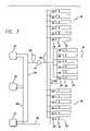
- FIG. 3is a schematic diagram of a distributed version of the galley refrigeration system for aircraft according to the invention.
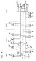
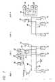
- FIG. 4is a schematic diagram of a first version of a layout of a distributed galley refrigeration system for aircraft according to the invention.
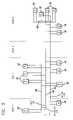
- FIG. 5is a schematic diagram of a second version of a layout of a distributed galley refrigeration system for aircraft according to the invention.
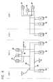
- FIG. 6is a schematic diagram of a third version of a layout of a distributed galley refrigeration system for aircraft according to the invention.
- FIG. 7is a schematic diagram of a fourth version of a layout of a distributed galley refrigeration system for aircraft according to the invention.
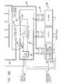
- FIGS. 8A and 8B togetherare a schematic diagram of an electronic control system for controlling the galley refrigeration system for aircraft according to the invention.
- FIG. 9is a schematic diagram of a galley air cooling unit of the galley refrigeration system for aircraft according to the invention.
- FIG. 10is a signal block diagram of an electronic control system for controlling the galley refrigeration system for aircraft according to the invention.
- FIG. 11is a diagram of a control panel for operation of the control system for controlling the galley refrigeration system for aircraft according to the invention.
- FIG. 12is an overall thermodynamic chart of the galley refrigeration system for aircraft according to the invention.
- the present inventionis directed to a system for refrigerating food carts within an aircraft galley system.
- the systemincludes a set of remote chillers which remove heat from a distributed liquid refrigerant system, which in turn removes heat from one or more food carts to refrigerate the food carts.
- the entire systemis electronically monitored and controlled to provide a sufficiently chilled environment within a potentially large number of food carts.
- the present inventionincludes three distributed refrigeration subsystems, and an electronic control subsystem for monitoring and controlling the refrigeration subsystems.
- the first refrigeration subsystemincludes at least one remote chiller
- the second refrigeration subsystemincludes at least one galley air cooling unit
- the third refrigeration subsystemincludes at least one recirculation unit.
- Each remote chillerconstitutes a self-contained refrigeration unit, which serves to remove heat from a liquid refrigerant, referred to as the intermediate working fluid.
- the intermediate working fluidis then distributed to the second refrigeration subsystem.
- the galley air cooling unitseach include a galley cart and a galley plenum.
- the chilled intermediate working fluidis distributed into and exits from a heat exchanger within the galley plenum.
- a blower or fan within the plenumblows air over the exchanger and through the galley cart. In this manner, the galley cart may be continually flushed with air chilled by the galley plenum heat exchanger.
- Each recirculation unitmay include one or more liquid pumps and expansion tank or accumulator.
- the one or more pumps of the recirculation unitspressurize the intermediate working fluid for redistribution to the remote chillers.
- the accumulators of the recirculation unitsallow for the storage and thermal expansion of the intermediate working fluid.
- the electronic control subsystemis also a distributed system which may monitor and control individual components of each refrigeration subsystem. Individual electronic devices may be used to monitor and control the temperature within each galley cart.
- the galley air cooling unitsmay include a control valve to vary the amount of liquid refrigerant entering the galley plenum.
- the electronic devices monitoring the temperature of the air in the galley cartmay be used to adjust the control valve. These same electronic devices may also be used to turn the fan in the galley plenum on and off.
- Other electronic devicesmay be used to monitor and control the recirculation units. These electronic devices monitor and control the recirculation units. These electronic devices may also be configured to monitor the pressure and volume within the expansion tank.
- the recirculation unitsmay be controlled by turning the pumps on and off or by varying the speeds by which the pumps operate.
- Other electronic devicesmay also be used to monitor and control the remote chillers. By monitoring the pressure and temperature within the remote chiller the electronic devices can appropriately determine which remote chillers to operate at different times.
- the electronic subsystemmay be powered by the aircraft electrical power systems.
- the electronic subsystemmay also include any number of display systems and interfaces for control by the crew.
- An overall control systemmay operate each individual electronic device.
- the entire system and each individual componentshould be configured for operation within the unique environment presented by transport aircraft.
- Equipment used on commercial aircraftmust meet strict requirements.
- general aircraft operating requirementsmust be met.
- the size and weight of the systemmust be kept to a minimum.
- the reliability and ease of maintenanceare key economic considerations.
- Fire suppression, non-toxicity and electromagnetic interference (EMI) shieldingare key safety considerations.
- the present inventionallows for these concerns, and others, to be met satisfactorily.
- a galley cart 20is typically stored within a galley plenum 22 while storing food. To safely store the food the air within the galley cart must be stored at or below a specific temperature. For example, 39° F. (4° C.) is the temperature required by certain agencies.
- the galley plenumis equipped with gaskets to form an air tight seal with the galley cart.
- the galley plenumis equipped with a blower 24 or fan which circulates air throughout the galley cart and over at least one heat exchanger 26 within the galley plenum.
- Ducts 25 between the galley cart and the galley plenumdirect the flow of air across the stored food.
- the heat exchanger 26 within the galley plenum 22may include a plate and fin configuration optimized for removing heat from passing air.
- the present inventioncontemplates the exchange of thermal energy between ambient air and a liquid refrigerant, also referred to as a heat transfer fluid, or the intermediate working fluid 27 .
- a known heat transfer fluid having appropriate thermal and physical properties for use with the present inventionis a fluorinated heat transfer fluid sold under the trademark GALDEN® HT 135.
- GALDEN® HT 135is a perfluoropolyether or PFPE fluid sold by the Ausimont Montedison Group, although other similar heat transfer fluids may also be suitable.
- each galley cart 20may require a thermal exchange of approximately 750–1000 BTUs per hour.
- the corresponding air flow requirement of each galley cart in such an arrangementwould then be approximately 72 cubic feet per minute.
- the corresponding fluid flow through each heat exchanger 26would be approximately 0.64 gallons per minute (using GALDEN®HT 135).
- Systems in accordance with the present inventionmay be designed to meet these requirements for as many galley carts as are used on an aircraft.
- a proportional flow valve 28may be used to control the flow of the intermediate working fluid 27 from each heat exchanger 26 within the galley plenum 22 . It is also contemplated that a single proportional flow valve may control the flow of fluid into two or more heat exchangers.
- One method of controlling the temperature of the air within the galley cart 20is to electronically manipulate the proportional flow valve so as to regulate the flow of fluid into the heat exchanger.
- the source of the chilled intermediate working fluidis at least one remote chiller unit 30 .
- the intermediate working fluidAfter exiting the heat exchanger 26 within the galley plenum 22 the intermediate working fluid is no longer chilled.
- the unchilled intermediate working fluidis returned to the chiller unit via the valve 28 , cooled, and redistributed throughout the system by at least one recirculation unit 32 .
- a simple system conforming to the present inventionmay consist of a remote chiller unit 30 and a redistribution unit 32 refrigerating several galley carts 20 .
- the liquid chiller unitmay be configured as a vapor cycle refrigeration unit.
- a compressor 34(a pump or other machine that increases the pressure of a gas) may be powered by the aircraft's electrical system.
- a rotary-type compressoris used to compress low temperature and pressure vapor into high temperature and pressure super-heated vapor.
- the material to form this vaporis also a refrigerant and may be referred to as a chiller working fluid 35 (See FIG. 1 ).
- a known material which has appropriate thermal and physical properties for use with the present inventions as the chiller working fluidis a hydrofluorocarbon refrigerant such as that sold under the name HFC-134a available from DuPont, or sold under the name MEFOREX 134a, or HT 134a, available from Ausimont, as a replacement for CFC12, although other similar refrigerants may also be suitable.
- a hydrofluorocarbon refrigerantsuch as that sold under the name HFC-134a available from DuPont, or sold under the name MEFOREX 134a, or HT 134a, available from Ausimont, as a replacement for CFC12, although other similar refrigerants may also be suitable.
- the chiller working fluid 35flows into a condenser 36 .
- the condenseris preferably configured as a tube-fin heat exchanger to maximize heat rejection.
- the chiller working fluidflows through an expansion valve 38 into an evaporator 40 .
- the evaporatoris preferably configured as a plate-fin heat exchanger to maximize heat absorption.
- an expelling heat exchanger 42Associated with the evaporator 40 is an expelling heat exchanger 42 .
- the intermediate working fluid 27flows through the expelling heat exchanger.
- the association of the evaporator with the expelling heat exchangerforms a chiller unit heat exchanger 43 (see FIG. 1 ) and enables a thermal exchange between the intermediate working fluid and the chiller working fluid 35 without the fluids ever mixing.
- the chiller working fluidpasses through the evaporator 40 , back into the compressor 34 , it draws heat from the expelling heat exchanger and the intermediate working fluid.
- a remote chiller unit 30 in accordance with this inventionmay be required to maintain a required low temperature in several galley carts 20 .
- the total heat rejection required of a single remote chiller unitmay be 18,000 BTUs per hour. This would require a flow rate of the intermediate working fluid 27 of 4.6 gallons per minute (using GALDEN®HT135). A corresponding flow rate through the condenser would be 700 cubic feet per minute at 3.5 inches H 2 O pressure (using HT-134a). This could be supplied by a condenser blower wheel operating at 5,750 revolutions per minute. Further requirements of such a remote chiller unit 30 may be an air venting fan as well as a mechanical bypass valve.
- the unchilled intermediate working fluid 27flows out of the heat exchanger 26 in the galley plenum 22 and is redistributed to a liquid pump 44 in at least one recirculation unit 32 .
- the liquid pumpmay be configured as a turbine impeller pump which delivers relatively high pressure at relatively low flow rates.
- the liquid pumpshould be entirely sealed to prevent any leakage of the intermediate working fluid.
- the liquid pumpssupply all the force required to maintain the circulation of the intermediate working fluid through the components of the system.
- the intermediate working fluid 27flows into an expansion tank 46 .
- the expansion tankfunctions as an accumulator and a reservoir for the intermediate working fluid.
- the expansion tankallows for thermal expansion of the intermediate working fluid.
- the intermediate working fluidremains in the liquid state.
- Each recirculation unit 32may gather intermediate working fluid 27 from several galley air cooling units 18 . Each recirculation unit may also provide intermediate working fluid to several remote chiller units 30 . As an example, the flow rate through a single recirculation unit may be 10 gallons per minute. The recirculation units may also be required to provide a pressure differential of 100 pounds per square inch in the intermediate working fluid.
- systems conforming to the present inventionmay be distributed systems. That is, a plurality of remote chiller units 30 may combine to remove heat from a plurality of galley carts 20 , and the entire system may be continually recirculated by at least one recirculation unit 32 . This permits the remote chiller units 30 and recirculation units 32 to be located at an accommodating distance from the galley carts 20 . Because of the limited space available on commercial transport aircraft this can be very advantageous.
- a network of ductsconnects the individual components.
- Supply ducts 48are configured to distribute the chilled intermediate working fluid to the galley air cooling units 18 .
- Redistribution ducts 49are configured to route the unchilled intermediate working fluid to the liquid pumps 44 .
- Return ducts 50are configured to distribute the unchilled intermediate working fluid to the remote chiller units 30 .
- FIGS. 4–7depict various configurations of the present invention.
- the differing configurations of various commercial aircraftrequire a great deal of flexibility in placement of remote chiller units 30 and recirculation units 32 .
- the supply ducts 48 , redistribution ducts 49 and return ducts 50may run potentially throughout the entire aircraft.
- the present inventionallows each of the components of the refrigeration system to be distributed to accommodating locations within the galleys or nearby.
- the present inventionmay also include a comprehensive electronic subsystem to monitor and control the distributed refrigeration system.
- a galley cart control device 52may be associated with each galley air cooling unit 18 .
- An air outlet temperature sensor 54 and an air supply temperature sensor 56may each provide input to the galley cart control device. The galley cart control device may then turn on or off the blower 24 as well as control the output of the proportional flow valve 28 .
- a chiller unit monitoring device 58may be associated with each remote chiller unit 30 .
- the chiller unit monitoring devicemay measure the function of the remote chiller unit. If needed, the chiller unit monitoring device could shut down the remote chiller unit.
- a system monitoring and control device 66may be associated with each recirculation unit 32 , or may be associated with the system as a whole.
- the system monitoring and control devicemay monitor the volume and pressure within each expansion tank 46 as well as the functioning of the liquid pumps 44 . Furthermore, the system monitoring device may monitor the temperature and pressure of the intermediate working fluid 27 at various locations within the system.
- the system monitoring and control devicemay also receive input from the chiller unit monitoring devices 58 and the galley cart control devices 52 . With this information, the system monitoring and control device may control the functioning of each and every electronic and refrigeration component of the entire system.
- the galley cart control device 52may control the temperature of the air in the galley cart 20 by regulating the flow of the intermediate working fluid 27 into the heat exchanger 26 within the galley plenum 22 .
- the air supply temperature sensor 56measures the temperature of the cold supply air and relays that information to the galley cart control device.
- the galley cart control devicecan increase or decrease the flow of intermediate working fluid by controlling the proportional control valve 28 . As the flow of the intermediate working fluid into the heat exchanger increases the temperature of the supply air will decrease and vice versa.
- the galley control devicemay also monitor the temperature of the intermediate working fluid at various locations or the temperature of the air returning to the heat exchanger. Furthermore, a differential pressure gauge 59 on the supply ducts 48 and a flow meter 61 on the redistribution ducts 49 may provide additional information about the flow of intermediate working fluid into and out of the galley air cooling unit 18 . The galley cart control device could use this further information to more efficiently regulate the proportional flow valve or to turn the blower 24 on and off.
- the components of the electronic subsystemmay be interrelated via the system monitoring and control device 66 also referred to as the recirculation unit with control logic. That is, the same electronic device used to monitor and control the recirculation unit 32 may be programmed to control the overall functioning of the entire system. This may include such functions as malfunction detection and providing maintenance information.
- Each galley cart control device 52 and chiller unit monitoring device 58may be configured to send signals to the system monitoring and control device relaying information about the status of the galley air cooling units 18 and remote chiller units 30 . In turn, the system monitoring and control device could send signals back to the galley cart control device and chiller unit monitoring device instructing the devices on how to control each galley air cooling unit and remote chiller unit.
- At least one display 70may be included with the electronic subsystem.
- the displayenables crew interface with the refrigeration system.
- a set of lightsindicates the status of the various components.
- a set of switchesmay permit crew control of the various components.
- the displaymay be electronically controlled by the system monitoring and control device 66 .
- FIG. 12depicts a thermodynamic chart showing the functioning of the refrigeration subsystems.
- the information provided by the chartis exemplary of a system in accordance with the present invention.
- the chartdepicts the refrigeration process as a series of heat exchanges between the various fluids involved in the process.
Landscapes
- Engineering & Computer Science (AREA)
- Aviation & Aerospace Engineering (AREA)
- Chemical & Material Sciences (AREA)
- Combustion & Propulsion (AREA)
- Physics & Mathematics (AREA)
- Mechanical Engineering (AREA)
- Thermal Sciences (AREA)
- General Engineering & Computer Science (AREA)
- Health & Medical Sciences (AREA)
- General Health & Medical Sciences (AREA)
- Pulmonology (AREA)
- Devices That Are Associated With Refrigeration Equipment (AREA)
Abstract
Description
Claims (10)
Priority Applications (6)
| Application Number | Priority Date | Filing Date | Title |
|---|---|---|---|
| US11/081,446US7137264B2 (en) | 2001-09-05 | 2005-03-16 | Liquid galley refrigeration system for aircraft |
| US11/603,262US7421849B2 (en) | 2001-09-05 | 2006-11-20 | Liquid galley refrigeration system for aircraft |
| US12/186,241US8151582B2 (en) | 2001-09-05 | 2008-08-05 | Liquid galley refrigeration system for aircraft |
| US13/424,024US8495887B2 (en) | 2001-09-05 | 2012-03-19 | Liquid galley refrigeration system for aircraft |
| US13/928,086US8813513B2 (en) | 2001-09-05 | 2013-06-26 | Liquid galley refrigeration system for aircraft |
| US14/451,762US20140338383A1 (en) | 2001-09-05 | 2014-08-05 | Liquid galley refrigeration system for aircraft |
Applications Claiming Priority (2)
| Application Number | Priority Date | Filing Date | Title |
|---|---|---|---|
| US09/947,222US6880351B2 (en) | 2001-09-05 | 2001-09-05 | Liquid galley refrigeration system for aircraft |
| US11/081,446US7137264B2 (en) | 2001-09-05 | 2005-03-16 | Liquid galley refrigeration system for aircraft |
Related Parent Applications (1)
| Application Number | Title | Priority Date | Filing Date |
|---|---|---|---|
| US09/947,222ContinuationUS6880351B2 (en) | 2001-09-05 | 2001-09-05 | Liquid galley refrigeration system for aircraft |
Related Child Applications (1)
| Application Number | Title | Priority Date | Filing Date |
|---|---|---|---|
| US11/603,262ContinuationUS7421849B2 (en) | 2001-09-05 | 2006-11-20 | Liquid galley refrigeration system for aircraft |
Publications (2)
| Publication Number | Publication Date |
|---|---|
| US20050178908A1 US20050178908A1 (en) | 2005-08-18 |
| US7137264B2true US7137264B2 (en) | 2006-11-21 |
Family
ID=25485768
Family Applications (7)
| Application Number | Title | Priority Date | Filing Date |
|---|---|---|---|
| US09/947,222Expired - LifetimeUS6880351B2 (en) | 2001-09-05 | 2001-09-05 | Liquid galley refrigeration system for aircraft |
| US11/081,446Expired - LifetimeUS7137264B2 (en) | 2001-09-05 | 2005-03-16 | Liquid galley refrigeration system for aircraft |
| US11/603,262Expired - LifetimeUS7421849B2 (en) | 2001-09-05 | 2006-11-20 | Liquid galley refrigeration system for aircraft |
| US12/186,241Expired - Fee RelatedUS8151582B2 (en) | 2001-09-05 | 2008-08-05 | Liquid galley refrigeration system for aircraft |
| US13/424,024Expired - Fee RelatedUS8495887B2 (en) | 2001-09-05 | 2012-03-19 | Liquid galley refrigeration system for aircraft |
| US13/928,086Expired - Fee RelatedUS8813513B2 (en) | 2001-09-05 | 2013-06-26 | Liquid galley refrigeration system for aircraft |
| US14/451,762AbandonedUS20140338383A1 (en) | 2001-09-05 | 2014-08-05 | Liquid galley refrigeration system for aircraft |
Family Applications Before (1)
| Application Number | Title | Priority Date | Filing Date |
|---|---|---|---|
| US09/947,222Expired - LifetimeUS6880351B2 (en) | 2001-09-05 | 2001-09-05 | Liquid galley refrigeration system for aircraft |
Family Applications After (5)
| Application Number | Title | Priority Date | Filing Date |
|---|---|---|---|
| US11/603,262Expired - LifetimeUS7421849B2 (en) | 2001-09-05 | 2006-11-20 | Liquid galley refrigeration system for aircraft |
| US12/186,241Expired - Fee RelatedUS8151582B2 (en) | 2001-09-05 | 2008-08-05 | Liquid galley refrigeration system for aircraft |
| US13/424,024Expired - Fee RelatedUS8495887B2 (en) | 2001-09-05 | 2012-03-19 | Liquid galley refrigeration system for aircraft |
| US13/928,086Expired - Fee RelatedUS8813513B2 (en) | 2001-09-05 | 2013-06-26 | Liquid galley refrigeration system for aircraft |
| US14/451,762AbandonedUS20140338383A1 (en) | 2001-09-05 | 2014-08-05 | Liquid galley refrigeration system for aircraft |
Country Status (1)
| Country | Link |
|---|---|
| US (7) | US6880351B2 (en) |
Cited By (7)
| Publication number | Priority date | Publication date | Assignee | Title |
|---|---|---|---|---|
| US20070084226A1 (en)* | 2001-09-05 | 2007-04-19 | George Simadiris | Liquid galley refrigeration system for aircraft |
| US20080196442A1 (en)* | 2007-02-20 | 2008-08-21 | B/E Aerospace, Inc. | Aircraft galley refrigeration system with multi-circuit heat exchanger |
| US20090068330A1 (en)* | 2007-09-10 | 2009-03-12 | David Flynn Stancil | Method for cooling |
| US20090301120A1 (en)* | 2008-06-05 | 2009-12-10 | B/E Aerospace, Inc. | Aircraft galley refrigeration system including a reduced weight and depth storage compartment cooling apparatus |
| US20100281892A1 (en)* | 2009-05-11 | 2010-11-11 | Schroder Bruce R | Compartment cooling loss identification for efficient system operation |
| US20110041532A1 (en)* | 2009-08-18 | 2011-02-24 | Preston Philip K | Low-Noise Fan Control for Refrigeration Cycle |
| US20120025679A1 (en)* | 2010-07-22 | 2012-02-02 | Sebastian Roering | Sealing system |
Families Citing this family (80)
| Publication number | Priority date | Publication date | Assignee | Title |
|---|---|---|---|---|
| US6505475B1 (en) | 1999-08-20 | 2003-01-14 | Hudson Technologies Inc. | Method and apparatus for measuring and improving efficiency in refrigeration systems |
| US7024874B2 (en)* | 2003-09-22 | 2006-04-11 | Hamilton Sundstrand | Aircraft galley chiller system |
| US6845627B1 (en)* | 2003-11-10 | 2005-01-25 | Be Intellectual Property, Inc. | Control system for an aircraft galley cooler |
| JP4200084B2 (en)* | 2003-12-01 | 2008-12-24 | 株式会社ジャムコ | Air chiller device |
| DE10361653B4 (en)* | 2003-12-30 | 2008-08-07 | Airbus Deutschland Gmbh | Cooling device for removing heat from an arranged in the interior of an aircraft heat source |
| DE10361645B4 (en)* | 2003-12-30 | 2008-06-26 | Airbus Deutschland Gmbh | Cooling system for cooling heat generating equipment in an aircraft |
| DE10361686B4 (en) | 2003-12-30 | 2008-04-24 | Airbus Deutschland Gmbh | Cooling system for cooling heat generating equipment in an aircraft |
| US7231778B2 (en)* | 2004-03-29 | 2007-06-19 | Be Intellectual Property, Inc. | Cooling system for a commercial aircraft galley |
| US7581698B2 (en)* | 2004-04-23 | 2009-09-01 | Airbus Deutschland Gmbh | Method and apparatus for tempering gaseous and/or liquid media in transportation vehicles, particularly in aircraft |
| US7198228B2 (en)* | 2004-09-15 | 2007-04-03 | The Boeing Company | Aircraft cabin crew complex |
| US7721797B2 (en) | 2005-04-25 | 2010-05-25 | Be Intellectual Property, Inc. | Refrigerator-oven combination for an aircraft galley food service system |
| EP1924810A1 (en)* | 2005-09-15 | 2008-05-28 | Chang Jo 21 Co., Ltd. | Air conditioning system for communication equipment and controlling method thereof |
| US7380408B2 (en)* | 2005-12-20 | 2008-06-03 | Hamilton Sunstrand Corporation | Integrated control system for combined galley refrigeration unit and cabin air conditioning system |
| DE102005061599A1 (en)* | 2005-12-22 | 2007-06-28 | Airbus Deutschland Gmbh | Modular cooling system and refrigeration device for such a cooling system |
| DE102006005035B3 (en)* | 2006-02-03 | 2007-09-27 | Airbus Deutschland Gmbh | cooling system |
| DE102006017012B4 (en)* | 2006-04-11 | 2011-01-13 | Airbus Operations Gmbh | Cooling system and freight container |
| US8118257B2 (en)* | 2006-04-28 | 2012-02-21 | Hamilton Sundstrand Corporation | Thermal management system with staged cooling |
| US8720217B2 (en)* | 2006-07-10 | 2014-05-13 | Mag Aerospace Industries, Inc. | Galley cooling heat sink through water system |
| DE102006040191A1 (en)* | 2006-08-28 | 2008-03-13 | Airbus Deutschland Gmbh | Cooling system for cooling heat loads on board in aircraft, has coupling system to selectively couple two cold carrier fluid circuits coupled to cold producing device and connected to corresponding heat load |
| DE102006052959B4 (en)* | 2006-11-09 | 2011-02-17 | Airbus Operations Gmbh | Cooling device for installation in an aircraft |
| US20080127666A1 (en)* | 2006-12-04 | 2008-06-05 | Gm Global Technology Operations, Inc. | Vehicle Heat Exchanger and Cooling System |
| US8161760B2 (en)* | 2006-12-28 | 2012-04-24 | Whirlpool Corporation | Utilities grid for distributed refrigeration system |
| US8336321B2 (en)* | 2006-12-28 | 2012-12-25 | Whirlpool Corporation | Hybrid multi-evaporator central cooling system for modular kitchen |
| US20090112407A1 (en)* | 2007-10-29 | 2009-04-30 | The Boeing Company | System and Method for Communication by Architecture |
| US9555892B2 (en) | 2008-07-29 | 2017-01-31 | The Boeing Company | Aircraft galley exhaust system and method of assembling same |
| US9238398B2 (en)* | 2008-09-25 | 2016-01-19 | B/E Aerospace, Inc. | Refrigeration systems and methods for connection with a vehicle's liquid cooling system |
| US8596089B2 (en)* | 2009-02-26 | 2013-12-03 | Honeywell International Inc. | Refrigerant distribution system |
| DE102009039814A1 (en)* | 2009-09-02 | 2011-03-10 | Airbus Operations Gmbh | System and method for cooling at least one heat-generating device in an aircraft |
| ES2906170T3 (en)* | 2009-09-10 | 2022-04-13 | Mitsubishi Electric Corp | Air conditioner |
| US20110186267A1 (en)* | 2010-02-01 | 2011-08-04 | Suna Display Co. | Heat transfer device with anisotropic thermal conducting micro structures |
| DE102010055241A1 (en)* | 2010-12-20 | 2012-06-21 | Airbus Operations Gmbh | Fluidic supply system with a plurality of consumers |
| EP2508336A1 (en)* | 2011-04-04 | 2012-10-10 | Industrial Neo Tex SA | Fire-proof plate |
| US20120291459A1 (en)* | 2011-05-17 | 2012-11-22 | The Boeing Company | Method and apparatus for aircraft galley cooling |
| US10266034B2 (en)* | 2011-06-16 | 2019-04-23 | Hamilton Sundstrand Corporation | Heat pump for supplemental heat |
| US9188380B2 (en) | 2011-08-23 | 2015-11-17 | B/E Aerospace, Inc. | Aircraft galley liquid cooling system |
| CN103842250B (en)* | 2011-08-30 | 2015-12-23 | B/E航空公司 | For the reconfigurable cooling-air outlet of galley cooling vessel |
| JP2013088031A (en)* | 2011-10-18 | 2013-05-13 | Hitachi Plant Technologies Ltd | Cooling system, and method for controlling the same |
| US9862496B2 (en) | 2012-03-30 | 2018-01-09 | B/E Aerospace, Inc. | Aircraft galley chiller system |
| EP2650216B1 (en)* | 2012-04-13 | 2014-08-13 | Airbus Operations GmbH | Cooling arrangement |
| US20150158594A1 (en)* | 2012-07-20 | 2015-06-11 | Sell Gmbh | Cooling concept back panel |
| US9745069B2 (en)* | 2013-01-21 | 2017-08-29 | Hamilton Sundstrand Corporation | Air-liquid heat exchanger assembly having a bypass valve |
| US20140352933A1 (en)* | 2013-05-28 | 2014-12-04 | Hamilton Sundstrand Corporation | Core assembly for a heat exchanger and method of assembling |
| JP6080952B2 (en)* | 2013-05-31 | 2017-02-15 | 三菱電機株式会社 | Heat medium conversion device and air conditioner equipped with the heat medium conversion device |
| US9676483B2 (en)* | 2013-07-03 | 2017-06-13 | B/E Aerospace, Inc. | Aircraft galley air chiller system |
| US10239618B2 (en)* | 2013-08-30 | 2019-03-26 | B/E Aerospace, Inc. | L shaped guide vanes for controlling and directing airflow in a galley chilled compartment |
| US10273010B2 (en)* | 2013-09-04 | 2019-04-30 | The Boeing Company | Systems and methods for refrigerating galley compartments |
| US10040556B2 (en) | 2013-10-07 | 2018-08-07 | B/E Aerospace, Inc. | Chilled air plenum system for aircraft galleys |
| US9986822B2 (en)* | 2014-05-01 | 2018-06-05 | The Boeing Company | Method and apparatus for cooling an airline galley cart using a skin heat exchanger |
| EP2942276B1 (en) | 2014-05-08 | 2017-04-26 | Airbus Operations GmbH | Galley assembly for a cabin of a vehicle, a cabin of a vehicle and an aircraft having a cabin and at least one such galley assembly |
| US10016055B2 (en) | 2014-07-08 | 2018-07-10 | B/E Aerospace, Inc. | Compact liquid cooled, air through galley chiller |
| US11085455B1 (en)* | 2014-08-11 | 2021-08-10 | Delta T, Llc | System for regulating airflow associated with product for sale |
| US9738389B2 (en)* | 2014-09-18 | 2017-08-22 | The Boeing Company | Systems and methods for cooling using galley monuments |
| DE102014117815A1 (en)* | 2014-12-03 | 2016-06-09 | Airbus Operations Gmbh | Line connection arrangement for installations in an aircraft cabin |
| US9957050B2 (en)* | 2015-05-19 | 2018-05-01 | The Boeing Company | Galley cart and galley system of an aircraft |
| US10252804B2 (en)* | 2015-05-19 | 2019-04-09 | The Boeing Company | Galley refrigeration system of an aircraft |
| US10492603B2 (en)* | 2015-05-19 | 2019-12-03 | The Boeing Company | Systems and methods of cooling a galley of an aircraft |
| EP3303136B1 (en)* | 2015-06-03 | 2020-11-04 | Airbus Operations GmbH | Space-optimised cooling system for a galley, and method of operating such a cooling system |
| US11072426B2 (en) | 2015-11-23 | 2021-07-27 | The Boeing Company | Galley system of an aircraft |
| DE102015016330A1 (en)* | 2015-12-17 | 2017-06-22 | Eisenmann Se | Zuluftanlage |
| US10188223B2 (en) | 2016-09-26 | 2019-01-29 | Hussmann Corporation | Refrigerated merchandiser including eutectic plate refrigeration |
| JP6790690B2 (en)* | 2016-10-04 | 2020-11-25 | 富士通株式会社 | Information processing system and control method of information processing system |
| JP6784281B2 (en)* | 2017-09-13 | 2020-11-11 | 株式会社デンソー | Equipment temperature controller |
| US10337776B2 (en) | 2017-09-19 | 2019-07-02 | The Boeing Company | Refrigeration system having valves and valve control actuators |
| DE102017127327A1 (en)* | 2017-11-20 | 2019-05-23 | Sig Technology Ag | Filling machine with cooling devices for cooling different plant parts |
| US10869412B2 (en)* | 2018-12-05 | 2020-12-15 | Google Llc | Provisioning data center server cooling equipment |
| US11661196B2 (en)* | 2019-06-25 | 2023-05-30 | B/E Aerospace, Inc. | Optimized electronics grounding path for high-frequency noise |
| US12377988B2 (en)* | 2019-09-16 | 2025-08-05 | B/E Aerospace, Inc. | Managing condensate drainage within chilled air ductwork |
| US11173768B2 (en) | 2019-10-03 | 2021-11-16 | Hamilton Sundstrand Corporation | Aircraft multi-zone environmental control systems |
| CN111186581A (en)* | 2019-12-11 | 2020-05-22 | 中国人民解放军空军勤务学院 | Airborne food heating assembly |
| US11591093B2 (en)* | 2020-04-29 | 2023-02-28 | The Boeing Company | Variable chiller exhaust with crown ventilation |
| US11796223B2 (en)* | 2020-09-15 | 2023-10-24 | B/E Aerospace, Inc. | System for preventing overheating in aircraft galley inserts |
| US20220111096A1 (en)* | 2020-10-14 | 2022-04-14 | The Boeing Company | Ultraviolet light sanitizing systems and methods |
| US12377180B2 (en) | 2020-12-11 | 2025-08-05 | The Boeing Company | Ultraviolet light-emitting module and disinfecting system |
| US12023413B2 (en) | 2020-12-11 | 2024-07-02 | The Boeing Company | Ultraviolet light-emitting module and disinfecting system |
| US12053554B2 (en) | 2020-12-11 | 2024-08-06 | The Boeing Company | Ultraviolet light-emitting module and disinfecting system |
| US12383640B2 (en) | 2020-12-11 | 2025-08-12 | The Boeing Company | Ultraviolet light-emitting assembly |
| US12165864B2 (en) | 2020-12-11 | 2024-12-10 | The Boeing Company | Ultraviolet light-emitting module and disinfecting system |
| US20230356119A1 (en)* | 2022-05-05 | 2023-11-09 | Hoffman Enclosures Inc. | Liquid Cooling System Fill Kit and Method of Use |
| US20230400241A1 (en)* | 2022-06-08 | 2023-12-14 | B/E Aerospace, Inc. | Method for packaging and ducting a micro-chiller-style heat sink into a cart bay or other enclosure for optimal air circulation |
| US12296959B2 (en) | 2022-06-08 | 2025-05-13 | B/E Aerospace, Inc. | In-seat mini-bar features |
Citations (11)
| Publication number | Priority date | Publication date | Assignee | Title |
|---|---|---|---|---|
| US2779171A (en) | 1954-01-04 | 1957-01-29 | Rca Corp | Room temperature conditioner |
| US3216215A (en) | 1964-02-27 | 1965-11-09 | Climate Inc | Temperature controlled incubator-hatchers |
| US4890463A (en) | 1985-05-13 | 1990-01-02 | Ital Idee S.R.L., An Italian Limited Liability Company | Absorption-type refrigeration system with thermal energy recovery, particularly for vehicles provided with an internal combustion engine |
| US5052472A (en) | 1989-07-19 | 1991-10-01 | Hitachi, Ltd. | LSI temperature control system |
| US5265437A (en) | 1990-11-26 | 1993-11-30 | Modine Manufacturing Co. | Automotive refrigeration system requiring minimal refrigerant |
| US5369960A (en) | 1992-08-22 | 1994-12-06 | Deutsche Aerospace Airbus Gmbh | Refrigeration system for an aircraft |
| US5491979A (en) | 1993-11-26 | 1996-02-20 | Daimler-Benz Aerospace Airbus Gmbh | Apparatus for cooling food stuffs, especially in an aircraft |
| US5496000A (en) | 1993-02-01 | 1996-03-05 | Daimler-Benz Aerospace Airbus Gmbh | System for storing and transporting food and beverages on board of aircraft |
| US5513500A (en) | 1993-11-26 | 1996-05-07 | Daimler-Benz Aerospace Airbus Gmbh | System for cooling food in an airplane |
| US6014866A (en) | 1997-04-17 | 2000-01-18 | Durham; James W. | Multiplex system for maintaining of product temperature in a vehicular distribution process |
| US6880351B2 (en)* | 2001-09-05 | 2005-04-19 | Be Intellectual Property, Inc. | Liquid galley refrigeration system for aircraft |
Family Cites Families (9)
| Publication number | Priority date | Publication date | Assignee | Title |
|---|---|---|---|---|
| US3675441A (en)* | 1970-11-19 | 1972-07-11 | Clark Equipment Co | Two stage refrigeration plant having a plurality of first stage refrigeration systems |
| US3992894A (en)* | 1975-12-22 | 1976-11-23 | International Business Machines Corporation | Inter-active dual loop cooling system |
| US4869071A (en)* | 1988-03-24 | 1989-09-26 | Sundstrand Corporation | Cooling system for an aircraft pod |
| US5406807A (en)* | 1992-06-17 | 1995-04-18 | Hitachi, Ltd. | Apparatus for cooling semiconductor device and computer having the same |
| US5960857A (en)* | 1996-02-07 | 1999-10-05 | Advantage Engineering, Inc. | System temperature control tank with integral modulator valve and flowmeter |
| US5743102A (en)* | 1996-04-15 | 1998-04-28 | Hussmann Corporation | Strategic modular secondary refrigeration |
| US5946926A (en)* | 1998-04-07 | 1999-09-07 | Hartman; Thomas B. | Variable flow chilled fluid cooling system |
| US6364709B1 (en)* | 2001-04-20 | 2002-04-02 | Hon Hai Precision Ind. Co., Ltd. | Small form-factor pluggable transceiver cage |
| US6434015B1 (en)* | 2001-12-03 | 2002-08-13 | Hon Hai Precision Ind. Co., Ltd. | Small form-factor pluggable module having release device |
- 2001
- 2001-09-05USUS09/947,222patent/US6880351B2/ennot_activeExpired - Lifetime
- 2005
- 2005-03-16USUS11/081,446patent/US7137264B2/ennot_activeExpired - Lifetime
- 2006
- 2006-11-20USUS11/603,262patent/US7421849B2/ennot_activeExpired - Lifetime
- 2008
- 2008-08-05USUS12/186,241patent/US8151582B2/ennot_activeExpired - Fee Related
- 2012
- 2012-03-19USUS13/424,024patent/US8495887B2/ennot_activeExpired - Fee Related
- 2013
- 2013-06-26USUS13/928,086patent/US8813513B2/ennot_activeExpired - Fee Related
- 2014
- 2014-08-05USUS14/451,762patent/US20140338383A1/ennot_activeAbandoned
Patent Citations (11)
| Publication number | Priority date | Publication date | Assignee | Title |
|---|---|---|---|---|
| US2779171A (en) | 1954-01-04 | 1957-01-29 | Rca Corp | Room temperature conditioner |
| US3216215A (en) | 1964-02-27 | 1965-11-09 | Climate Inc | Temperature controlled incubator-hatchers |
| US4890463A (en) | 1985-05-13 | 1990-01-02 | Ital Idee S.R.L., An Italian Limited Liability Company | Absorption-type refrigeration system with thermal energy recovery, particularly for vehicles provided with an internal combustion engine |
| US5052472A (en) | 1989-07-19 | 1991-10-01 | Hitachi, Ltd. | LSI temperature control system |
| US5265437A (en) | 1990-11-26 | 1993-11-30 | Modine Manufacturing Co. | Automotive refrigeration system requiring minimal refrigerant |
| US5369960A (en) | 1992-08-22 | 1994-12-06 | Deutsche Aerospace Airbus Gmbh | Refrigeration system for an aircraft |
| US5496000A (en) | 1993-02-01 | 1996-03-05 | Daimler-Benz Aerospace Airbus Gmbh | System for storing and transporting food and beverages on board of aircraft |
| US5491979A (en) | 1993-11-26 | 1996-02-20 | Daimler-Benz Aerospace Airbus Gmbh | Apparatus for cooling food stuffs, especially in an aircraft |
| US5513500A (en) | 1993-11-26 | 1996-05-07 | Daimler-Benz Aerospace Airbus Gmbh | System for cooling food in an airplane |
| US6014866A (en) | 1997-04-17 | 2000-01-18 | Durham; James W. | Multiplex system for maintaining of product temperature in a vehicular distribution process |
| US6880351B2 (en)* | 2001-09-05 | 2005-04-19 | Be Intellectual Property, Inc. | Liquid galley refrigeration system for aircraft |
Cited By (16)
| Publication number | Priority date | Publication date | Assignee | Title |
|---|---|---|---|---|
| US8151582B2 (en)* | 2001-09-05 | 2012-04-10 | Be Aerospace, Inc. | Liquid galley refrigeration system for aircraft |
| US7421849B2 (en)* | 2001-09-05 | 2008-09-09 | Be Intellectual Property, Inc. | Liquid galley refrigeration system for aircraft |
| US20080289800A1 (en)* | 2001-09-05 | 2008-11-27 | Be Intellectual Property, Inc. | Liquid galley refrigeration system for aircraft |
| US20070084226A1 (en)* | 2001-09-05 | 2007-04-19 | George Simadiris | Liquid galley refrigeration system for aircraft |
| US8813513B2 (en)* | 2001-09-05 | 2014-08-26 | B/E Aerospace, Inc. | Liquid galley refrigeration system for aircraft |
| US8495887B2 (en) | 2001-09-05 | 2013-07-30 | Be Aerospace, Inc. | Liquid galley refrigeration system for aircraft |
| US20080196442A1 (en)* | 2007-02-20 | 2008-08-21 | B/E Aerospace, Inc. | Aircraft galley refrigeration system with multi-circuit heat exchanger |
| US8607586B2 (en)* | 2007-02-20 | 2013-12-17 | B/E Aerospace, Inc. | Aircraft galley refrigeration system with multi-circuit heat exchanger |
| US20090068330A1 (en)* | 2007-09-10 | 2009-03-12 | David Flynn Stancil | Method for cooling |
| US20090301120A1 (en)* | 2008-06-05 | 2009-12-10 | B/E Aerospace, Inc. | Aircraft galley refrigeration system including a reduced weight and depth storage compartment cooling apparatus |
| US8171745B2 (en) | 2009-05-11 | 2012-05-08 | Hamilton Sundstrand Corporation | Compartment cooling loss identification for efficient system operation |
| US20100281892A1 (en)* | 2009-05-11 | 2010-11-11 | Schroder Bruce R | Compartment cooling loss identification for efficient system operation |
| US8375733B2 (en) | 2009-08-18 | 2013-02-19 | Polyscience | Low-noise fan control for refrigeration cycle |
| US20110041532A1 (en)* | 2009-08-18 | 2011-02-24 | Preston Philip K | Low-Noise Fan Control for Refrigeration Cycle |
| US20120025679A1 (en)* | 2010-07-22 | 2012-02-02 | Sebastian Roering | Sealing system |
| US9045229B2 (en)* | 2010-07-22 | 2015-06-02 | Airbus Operations Gmbh | Sealing system |
Also Published As
| Publication number | Publication date |
|---|---|
| US6880351B2 (en) | 2005-04-19 |
| US7421849B2 (en) | 2008-09-09 |
| US20140000837A1 (en) | 2014-01-02 |
| US20140338383A1 (en) | 2014-11-20 |
| US20080289800A1 (en) | 2008-11-27 |
| US8151582B2 (en) | 2012-04-10 |
| US8813513B2 (en) | 2014-08-26 |
| US20030042361A1 (en) | 2003-03-06 |
| US20070084226A1 (en) | 2007-04-19 |
| US8495887B2 (en) | 2013-07-30 |
| US20050178908A1 (en) | 2005-08-18 |
| US20120222443A1 (en) | 2012-09-06 |
Similar Documents
| Publication | Publication Date | Title |
|---|---|---|
| US7137264B2 (en) | Liquid galley refrigeration system for aircraft | |
| US6832504B1 (en) | Liquid sensing system for an aircraft galley cooler using a two phase working fluid | |
| CA2545848C (en) | Control system for an aircraft galley cooler | |
| US7231778B2 (en) | Cooling system for a commercial aircraft galley | |
| EP1670683B8 (en) | Aircraft galley chiller system | |
| US9188380B2 (en) | Aircraft galley liquid cooling system | |
| CN100430298C (en) | Cooling system for cooling heat-generating devices in an aircraft | |
| EP3095698B1 (en) | Galley cart refrigeration system of an aircraft | |
| HK1094350B (en) | Liquid sensing system for an aircraft galley cooler using a two phase working fluid | |
| EP1878660A2 (en) | Aircraft galley chiller system | |
| HK1094981B (en) | Control system for an aircraft galley cooler |
Legal Events
| Date | Code | Title | Description |
|---|---|---|---|
| STCF | Information on status: patent grant | Free format text:PATENTED CASE | |
| AS | Assignment | Owner name:JPMORGAN CHASE BANK, N.A., TEXAS Free format text:SECURITY AGREEMENT;ASSIGNOR:BE AEROSPACE, INC.;REEL/FRAME:021393/0273 Effective date:20080728 Owner name:JPMORGAN CHASE BANK, N.A.,TEXAS Free format text:SECURITY AGREEMENT;ASSIGNOR:BE AEROSPACE, INC.;REEL/FRAME:021393/0273 Effective date:20080728 | |
| AS | Assignment | Owner name:BE AEROSPACE, INC., FLORIDA Free format text:RELEASE BY SECURED PARTY;ASSIGNOR:JP MORGAN CHASE BANK, N.A.;REEL/FRAME:021398/0978 Effective date:20080728 Owner name:BE AEROSPACE, INC.,FLORIDA Free format text:RELEASE BY SECURED PARTY;ASSIGNOR:JP MORGAN CHASE BANK, N.A.;REEL/FRAME:021398/0978 Effective date:20080728 | |
| FPAY | Fee payment | Year of fee payment:4 | |
| AS | Assignment | Owner name:B/E AEROSPACE, INC., FLORIDA Free format text:CHANGE OF NAME;ASSIGNOR:BE AEROSPACE, INC.;REEL/FRAME:031600/0945 Effective date:20120730 | |
| FPAY | Fee payment | Year of fee payment:8 | |
| AS | Assignment | Owner name:B/E AEROSPACE, INC., FLORIDA Free format text:RELEASE BY SECURED PARTY;ASSIGNOR:JP MORGAN CHASE BANK, N.A.;REEL/FRAME:034805/0718 Effective date:20141216 | |
| AS | Assignment | Owner name:B/E AEROSPACE, INC., FLORIDA Free format text:CORRECTIVE ASSIGNMENT TO CORRECT THE INCORRECT APPL. NO. 13/071,416 PREVIOUSLY RECORDED AT REEL: 031600 FRAME: 0945. ASSIGNOR(S) HEREBY CONFIRMS THE CHANGE OF NAME;ASSIGNOR:BE AEROSPACE, INC.;REEL/FRAME:036242/0530 Effective date:20120730 | |
| MAFP | Maintenance fee payment | Free format text:PAYMENT OF MAINTENANCE FEE, 12TH YEAR, LARGE ENTITY (ORIGINAL EVENT CODE: M1553) Year of fee payment:12 | |
| AS | Assignment | Owner name:B/E AEROSPACE, INC., FLORIDA Free format text:RELEASE BY SECURED PARTY;ASSIGNOR:JP MORGAN CHASE BANK, N.A;REEL/FRAME:049209/0619 Effective date:20170413 |