US7137256B1 - Method of operating a combustion system for increased turndown capability - Google Patents
Method of operating a combustion system for increased turndown capabilityDownload PDFInfo
- Publication number
- US7137256B1 US7137256B1US10/906,631US90663105AUS7137256B1US 7137256 B1US7137256 B1US 7137256B1US 90663105 AUS90663105 AUS 90663105AUS 7137256 B1US7137256 B1US 7137256B1
- Authority
- US
- United States
- Prior art keywords
- stage
- stage injectors
- fuel flow
- injectors
- flow split
- Prior art date
- Legal status (The legal status is an assumption and is not a legal conclusion. Google has not performed a legal analysis and makes no representation as to the accuracy of the status listed.)
- Expired - Lifetime
Links
Images


Classifications
- F—MECHANICAL ENGINEERING; LIGHTING; HEATING; WEAPONS; BLASTING
- F02—COMBUSTION ENGINES; HOT-GAS OR COMBUSTION-PRODUCT ENGINE PLANTS
- F02C—GAS-TURBINE PLANTS; AIR INTAKES FOR JET-PROPULSION PLANTS; CONTROLLING FUEL SUPPLY IN AIR-BREATHING JET-PROPULSION PLANTS
- F02C7/00—Features, components parts, details or accessories, not provided for in, or of interest apart form groups F02C1/00 - F02C6/00; Air intakes for jet-propulsion plants
- F02C7/22—Fuel supply systems
- F02C7/228—Dividing fuel between various burners
- F—MECHANICAL ENGINEERING; LIGHTING; HEATING; WEAPONS; BLASTING
- F23—COMBUSTION APPARATUS; COMBUSTION PROCESSES
- F23R—GENERATING COMBUSTION PRODUCTS OF HIGH PRESSURE OR HIGH VELOCITY, e.g. GAS-TURBINE COMBUSTION CHAMBERS
- F23R3/00—Continuous combustion chambers using liquid or gaseous fuel
- F23R3/28—Continuous combustion chambers using liquid or gaseous fuel characterised by the fuel supply
- F23R3/34—Feeding into different combustion zones
- F23R3/343—Pilot flames, i.e. fuel nozzles or injectors using only a very small proportion of the total fuel to insure continuous combustion
Definitions
- This inventionrelates in general to gas turbine combustion systems and specifically to a method of operating a gas turbine combustion system at significantly lower load conditions while having stable combustion and lower emissions.
- Gas turbine enginestypically include a compressor, one or more combustors each having a fuel injection system, and a turbine section. In an engine having a plurality of combustors, they are typically arranged in an annular array about the engine and most typically interconnected for the purposes of ignition.
- the compressorraises the pressure of inlet air, and then directs it to the combustors, where it is used to cool the combustion chamber walls as well to provide air for the combustion process.
- compressed airis mixed with a fuel and the mixture is ignited by an ignition source to produce hot combustion gases.
- ignitionoccurs within a single chamber, and for engines with multiple combustors, the flame passes through tubes interconnecting the combustors to ignite the fuel air mixture in the adjacent combustor.
- 5,924,275discloses a method of operating a combustor that utilizes the addition of a center pilot nozzle in combination with the previously mentioned assymetrical fuel staging to provide reduced emissions at lower load conditions. While this staging method and combustor configuration is an enhancement, it is still limited in turndown capability, such that in order to achieve turndown to low, part-load settings, the combustor must often revert to the higher emissions diffusion mode and not operate in the lower emissions premix mode.
- An effort to overcome the shortcomings of the prior artwas disclosed by co-pending U.S. patent application Ser. No. 10/437,748 assigned to the same assignee as the present invention. However, this prior patent application for staging fuel to produce low emissions at low load settings was directed to a combustor configuration having a can-annular configuration in which adjacent combustors communicated with each other via crossfire tubes.
- a further problem with shutting down the engineis the additional cycles that are incurred by the engine hardware.
- a cycleis commonly defined as the engine passing through the normal operating envelope and thereby exposing the engine hardware to a complete cycle of pressures and temperatures that over time cause wear to the engine hardware.
- Engine manufacturerstypically rate hardware life in terms of operating hours or equivalent operating cycles. Therefore, incurring additional cycles can reduce hardware life requiring premature repair or replacement at the expense of the engine operator.
- This systemshould be one that can be efficiently operated at lower load conditions, thereby eliminating the wasted fuel when high load operation is not demanded or incurring the additional cycles on the engine hardware when shutting down.
- the present inventionseeks to overcome the shortfalls of the prior art by providing a method of operating a combustion system that provides stable combustion having low NOx and CO emissions throughout all load conditions. This is accomplished through a plurality of fuel stages, including axial, radial, and circumferential staging.
- the combustion systemincludes a plurality of injectors staged radially, axially, and circumferentially.
- a can combustion systemcomprising a plurality of first stage injectors arranged in a first array about a center axis and a plurality of second stage injectors arranged in a second array radially outward of the first array and proximate a first swirler.
- the combustion systemalso comprises an aft injector assembly having a manifold, which is located axially downstream of the end cover and radially outward of the liner.
- the manifold of the aft injector assemblycomprises a plurality of third stage injectors and a plurality of fourth stage injectors, each of which are arranged in sectors with the plurality of third stage injectors encompassing approximately one third of the aft injector assembly while the plurality of fourth stage injectors encompass the remaining two thirds of the aft injector assembly.
- a spark ignition sourceis utilized to ignite the fuel and air mixture within each combustor.
- the plurality of first stage injectorsare repositioned to the aft injector assembly such that the plurality of first stage injectors, plurality of third stage injectors, and plurality of fourth stage injectors each encompass approximately one third of the aft injector assembly.
- This repositioning of the plurality of first stage injectorsis necessary if an alternate form of ignition, a torch igniter, is utilized.
- a torch igniterwhich is a more reliable form of ignition due to its dedicated fuel source, may be necessary depending on the operating conditions. If a torch igniter is selected, then the fuel supplied by the plurality of first stage injectors is not necessary for ignition and is restaged such that it is premixed instead via the aft injector assembly.
- the combustion system disclosed in the present inventioncontains both a spark igniter and torch igniter for redundancy and operator choice.
- the present inventiondiscloses an operating sequence for each of the four fuel stages identified such that emissions are kept within required levels while operating reliably at low load conditions. This is accomplished initially at combustor ignition by supplying fuel to plurality of first stage injectors and plurality of second stage injectors and gradually increasing fuel flow split to the plurality of first stage injectors and decreasing fuel flow split to plurality of second stage injectors until all fuel flows through plurality of first stage injectors at an engine full speed no load condition. Fuel flow split to the plurality of first stage injectors is maintained until a first part-load condition.
- Fuel flow splitthen gradually decreases to the plurality of first stage injectors while gradually increasing the fuel flow split to a plurality of second stage injectors until all fuel injected into the combustion system is directed through the plurality of second stage injectors at a second part load condition and maintaining all fuel flow to the plurality of second stage injectors until a third part load condition.
- fuel flow split to the plurality of second stage injectorsis reduced while fuel flow split the plurality of third stage injectors is increased.
- fuel flow splitis further decreased to the plurality of second stage injectors and further increased to the plurality of third stage injectors up to a fourth part load condition.
- FIG. 1is a cross section of a combustion system that operates in accordance with the preferred embodiment of the present invention.
- FIG. 2is a cross section taken through a portion of the combustion system of FIG. 1 in accordance with the preferred embodiment of the present invention.
- FIG. 3is a detailed view of a portion of the aft injector assembly in accordance with the preferred embodiment of the present invention.
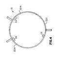
- FIG. 4is a cross section schematic representative of the aft injector assembly in accordance with the preferred embodiment of the present invention.
- FIG. 5is a cross section schematic representative of the aft injector assembly in accordance with an alternate embodiment of the present invention.
- FIG. 6is a diagram depicting fuel flow split rates for each stage of fuel injectors as a function of engine condition for the preferred embodiment of the present invention.
- Combustion system 10for a gas turbine engine is shown in cross section.
- Combustion system 10comprises casing 11 , end cover 12 , combustion liner 13 , and a center axis A—A.
- Casing 11which is mounted to an engine through flange 14 , is in fluid communication with compressed air from a compressor.
- An end cover 12is fixed to casing first end 15 , with end cover 12 having at least one fuel source in fluid communication with at least one set of injectors.
- a first fuel source 16is in fluid communication with a plurality of first stage injectors 17 , where plurality of first stage injectors 17 are arranged in a first array about center axis A—A.
- end cover 12also contains a second fuel source 18 in fluid communication with a plurality of second stage injectors 19 , where plurality of second stage injectors 19 are arranged in a second array radially outward of first stage injectors 17 proximate a first swirler 20 .
- the combustion system of the present inventionfurther comprises an aft injector assembly 21 , which is shown in FIG. 1 and in cross section in FIGS. 2 and 3 .
- Aft injector assembly 21comprises a manifold 22 having a plurality of third stage injectors 23 and a plurality of fourth stage injectors 24 .
- Third stage injectors 23 and fourth stage injectors 24are arranged in sectors in aft injector assembly 21 . These sectors are better understood with reference to FIG. 4 , which is a schematic cross section view of aft injector assembly 21 .
- Manifold 22 of aft injector assembly 21is divided into three sectors 22 A, 22 B, and 22 C.
- sector 22 Ccontains plurality of third stage injectors 23 while sectors 22 A and 22 B contain plurality of fourth stage injectors 24 .
- plurality of third stage injectors 23encompass approximately one-third of manifold 22 in aft injector assembly 21 while plurality of fourth stage injectors 24 encompass the remaining approximately two-thirds of manifold 22 .
- Each sector, 22 A, 22 B, and 22 Ccontain a separate fuel inlet location for supplying fuel to the sector, where for the preferred embodiment, fuel to sectors 22 A and 22 B are supplied from the same source so that each fourth stage injector 24 receives a uniform fuel flow split.
- the exact quantity and size of injectors 23 and 24depends on the desired fuel flow split and mixing and is at the discretion of the combustion designer.
- combustion system 10further comprises a second swirler 26 adjacent aft injector assembly 21 .
- plurality of first stage injectors 17are repositioned to aft injector assembly 21 in sector 22 B of manifold 22 .
- manifold 22By dividing manifold 22 into three sectors, each encompassing approximately one-third of manifold 22 , it allows for easy repositioning of the plurality of first stage injectors by simply changing the first stage fuel inlet location from end cover 12 to aft injector assembly 21 without requiring any other major hardware changes, should that change be necessary or desirable.
- Repositioning plurality of first stage injectors 17 to aft injector assembly 21not only is a relatively simple adjustment to make, but also allows greater flexibility for staging fuel injection through the aft injector assembly.
- a fuelpreferably natural gas
- a fuelis supplied to plurality of first stage injectors 17 and plurality of second stage injectors 19 so as to inject the fuel into a surrounding air flow to form a mixture.
- This mixtureis then ignited by the ignition source, which for the preferred embodiment is a spark igniter.
- the ignition sourcewhich for the preferred embodiment is a spark igniter.
- fuel flow splitgradually increases to plurality of first stage injectors 17 and gradually decreases to plurality of second stage injectors 19 until all fuel to combustion system 10 is flowing through plurality of first stage injectors 17 at an engine full speed no load condition.
- fuel flow split to plurality of first stage injectors 17is maintained until a first part load condition is achieved.
- fuel flow split to plurality of first stage injectors 17gradually decreases while fuel flow split to plurality of second stage injectors 19 is reinitiated and gradually increases until all fuel to combustion system 10 is flowing through plurality of second stage injectors 19 at a second part load condition.
- fuel flow split to plurality of second stage injectors 19is maintained until a third part load condition is achieved.
- fuel flow split to plurality of second stage injectors 19is reduced while simultaneously directing flow to and increasing fuel flow split to plurality of third stage injectors 23 .
- fuel flow split to plurality of second stage injectors 19further decreases while fuel flow split plurality of third stage injectors 23 continues to increase until a fourth part load condition is achieved.
- fuel flow split to both plurality of second stage injectors 19 and third stage injectors 23is reduced while directing fuel to flow through the plurality of fourth stage injectors 24 and increasing the fuel flow split to plurality of fourth stage injectors 24 . From this point, with fuel flowing through plurality of second stage injectors 19 , plurality of third stage injectors 23 , and plurality of fourth stage injectors 24 , fuel flow split is maintained until the gas turbine engine reaches a full load condition.
- NOx and CO emissionsare maintained within regulated parameters. This is accomplished by increasing and decreasing fuel flow split rates to each stage as required to support the required load condition, while not burning the fuel air mixture at a high enough temperature to generate excessive NOx nor quenching the flame to produce higher than desired CO levels.
- the method of the present inventiondescribes a combustion system operation that can provide flame stability and low emissions benefits throughout the full operating conditions of the gas turbine engine, including a low part-load condition. Therefore, the gas turbine can be operated efficiently at lower load conditions, thereby eliminating wasted fuel when high load operation is not demanded or incurring the additional cycles on the engine hardware when shutting down.
Landscapes
- Engineering & Computer Science (AREA)
- Chemical & Material Sciences (AREA)
- Combustion & Propulsion (AREA)
- Mechanical Engineering (AREA)
- General Engineering & Computer Science (AREA)
Abstract
Description
Claims (11)
Priority Applications (1)
| Application Number | Priority Date | Filing Date | Title |
|---|---|---|---|
| US10/906,631US7137256B1 (en) | 2005-02-28 | 2005-02-28 | Method of operating a combustion system for increased turndown capability |
Applications Claiming Priority (1)
| Application Number | Priority Date | Filing Date | Title |
|---|---|---|---|
| US10/906,631US7137256B1 (en) | 2005-02-28 | 2005-02-28 | Method of operating a combustion system for increased turndown capability |
Publications (1)
| Publication Number | Publication Date |
|---|---|
| US7137256B1true US7137256B1 (en) | 2006-11-21 |
Family
ID=37423117
Family Applications (1)
| Application Number | Title | Priority Date | Filing Date |
|---|---|---|---|
| US10/906,631Expired - LifetimeUS7137256B1 (en) | 2005-02-28 | 2005-02-28 | Method of operating a combustion system for increased turndown capability |
Country Status (1)
| Country | Link |
|---|---|
| US (1) | US7137256B1 (en) |
Cited By (99)
| Publication number | Priority date | Publication date | Assignee | Title |
|---|---|---|---|---|
| US20060150634A1 (en)* | 2005-01-07 | 2006-07-13 | Power Systems Mfg., Llc | Apparatus and Method for Reducing Carbon Monoxide Emissions |
| US20100043387A1 (en)* | 2007-11-01 | 2010-02-25 | Geoffrey David Myers | Methods and systems for operating gas turbine engines |
| US20100146928A1 (en)* | 2008-12-17 | 2010-06-17 | Oleg Morenko | Fuel manifold for gas turbine engine |
| US20120279223A1 (en)* | 2011-05-03 | 2012-11-08 | Carl Robert Barker | Fuel Injector and Support Plate |
| US8418468B2 (en) | 2010-04-06 | 2013-04-16 | General Electric Company | Segmented annular ring-manifold quaternary fuel distributor |
| US8438852B2 (en) | 2010-04-06 | 2013-05-14 | General Electric Company | Annular ring-manifold quaternary fuel distributor |
| US8677753B2 (en) | 2012-05-08 | 2014-03-25 | General Electric Company | System for supplying a working fluid to a combustor |
| WO2014055435A2 (en) | 2012-10-01 | 2014-04-10 | Alstom Technology Ltd. | Variable flow divider mechanism for a multi-stage combustor |
| WO2014055437A1 (en) | 2012-10-01 | 2014-04-10 | Alstom Technology Ltd. | Method of operating a multi-stage flamesheet combustor |
| US20140109586A1 (en)* | 2012-10-22 | 2014-04-24 | Alstom Technology Ltd | Method for operating a gas turbine with sequential combustion and gas turbine for conducting said method |
| US8734545B2 (en) | 2008-03-28 | 2014-05-27 | Exxonmobil Upstream Research Company | Low emission power generation and hydrocarbon recovery systems and methods |
| US20140150438A1 (en)* | 2012-11-30 | 2014-06-05 | General Electric Company | System and method for operating a gas turbine in a turndown mode |
| WO2014099091A2 (en) | 2012-10-01 | 2014-06-26 | Alstom Technology Ltd. | Thermally free liner retention mechanism |
| CN104047726A (en)* | 2013-03-15 | 2014-09-17 | 通用电气公司 | Methods relating to downstream fuel and air injection in gas turbines |
| US20140260269A1 (en)* | 2013-03-15 | 2014-09-18 | General Electric Company | Systems and apparatus relating to downstream fuel and air injection in gas turbines |
| US8973366B2 (en) | 2011-10-24 | 2015-03-10 | General Electric Company | Integrated fuel and water mixing assembly for use in conjunction with a combustor |
| US8984857B2 (en) | 2008-03-28 | 2015-03-24 | Exxonmobil Upstream Research Company | Low emission power generation and hydrocarbon recovery systems and methods |
| US8991187B2 (en) | 2010-10-11 | 2015-03-31 | General Electric Company | Combustor with a lean pre-nozzle fuel injection system |
| US9027321B2 (en) | 2008-03-28 | 2015-05-12 | Exxonmobil Upstream Research Company | Low emission power generation and hydrocarbon recovery systems and methods |
| US9052115B2 (en) | 2012-04-25 | 2015-06-09 | General Electric Company | System and method for supplying a working fluid to a combustor |
| US9097424B2 (en) | 2012-03-12 | 2015-08-04 | General Electric Company | System for supplying a fuel and working fluid mixture to a combustor |
| US9151500B2 (en) | 2012-03-15 | 2015-10-06 | General Electric Company | System for supplying a fuel and a working fluid through a liner to a combustion chamber |
| US9170024B2 (en) | 2012-01-06 | 2015-10-27 | General Electric Company | System and method for supplying a working fluid to a combustor |
| US9188061B2 (en) | 2011-10-24 | 2015-11-17 | General Electric Company | System for turbine combustor fuel assembly |
| US9188337B2 (en) | 2012-01-13 | 2015-11-17 | General Electric Company | System and method for supplying a working fluid to a combustor via a non-uniform distribution manifold |
| US9222671B2 (en) | 2008-10-14 | 2015-12-29 | Exxonmobil Upstream Research Company | Methods and systems for controlling the products of combustion |
| US9243804B2 (en) | 2011-10-24 | 2016-01-26 | General Electric Company | System for turbine combustor fuel mixing |
| US9267433B2 (en) | 2011-10-24 | 2016-02-23 | General Electric Company | System and method for turbine combustor fuel assembly |
| US9267436B2 (en)* | 2013-03-18 | 2016-02-23 | General Electric Company | Fuel distribution manifold for a combustor of a gas turbine |
| US9284888B2 (en) | 2012-04-25 | 2016-03-15 | General Electric Company | System for supplying fuel to late-lean fuel injectors of a combustor |
| US20160084169A1 (en)* | 2012-10-01 | 2016-03-24 | Peter John Stuttaford | Method of operating a multi-stage flamesheet combustor |
| US20160146464A1 (en)* | 2014-11-25 | 2016-05-26 | General Electric Technology Gmbh | Combustor with annular bluff body |
| US9353682B2 (en) | 2012-04-12 | 2016-05-31 | General Electric Company | Methods, systems and apparatus relating to combustion turbine power plants with exhaust gas recirculation |
| US9429325B2 (en) | 2011-06-30 | 2016-08-30 | General Electric Company | Combustor and method of supplying fuel to the combustor |
| US9463417B2 (en) | 2011-03-22 | 2016-10-11 | Exxonmobil Upstream Research Company | Low emission power generation systems and methods incorporating carbon dioxide separation |
| US9512759B2 (en) | 2013-02-06 | 2016-12-06 | General Electric Company | System and method for catalyst heat utilization for gas turbine with exhaust gas recirculation |
| US20170002742A1 (en)* | 2015-06-30 | 2017-01-05 | Stephen W. Jorgensen | Fuel injection locations based on combustor flow path |
| US9574496B2 (en) | 2012-12-28 | 2017-02-21 | General Electric Company | System and method for a turbine combustor |
| US9581081B2 (en) | 2013-01-13 | 2017-02-28 | General Electric Company | System and method for protecting components in a gas turbine engine with exhaust gas recirculation |
| US9587510B2 (en) | 2013-07-30 | 2017-03-07 | General Electric Company | System and method for a gas turbine engine sensor |
| US9593851B2 (en) | 2011-06-30 | 2017-03-14 | General Electric Company | Combustor and method of supplying fuel to the combustor |
| US9599021B2 (en) | 2011-03-22 | 2017-03-21 | Exxonmobil Upstream Research Company | Systems and methods for controlling stoichiometric combustion in low emission turbine systems |
| US9599070B2 (en) | 2012-11-02 | 2017-03-21 | General Electric Company | System and method for oxidant compression in a stoichiometric exhaust gas recirculation gas turbine system |
| US9611756B2 (en) | 2012-11-02 | 2017-04-04 | General Electric Company | System and method for protecting components in a gas turbine engine with exhaust gas recirculation |
| US9617914B2 (en) | 2013-06-28 | 2017-04-11 | General Electric Company | Systems and methods for monitoring gas turbine systems having exhaust gas recirculation |
| US9618261B2 (en) | 2013-03-08 | 2017-04-11 | Exxonmobil Upstream Research Company | Power generation and LNG production |
| US9631815B2 (en) | 2012-12-28 | 2017-04-25 | General Electric Company | System and method for a turbine combustor |
| US9631542B2 (en) | 2013-06-28 | 2017-04-25 | General Electric Company | System and method for exhausting combustion gases from gas turbine engines |
| US9670841B2 (en) | 2011-03-22 | 2017-06-06 | Exxonmobil Upstream Research Company | Methods of varying low emission turbine gas recycle circuits and systems and apparatus related thereto |
| US9689309B2 (en) | 2011-03-22 | 2017-06-27 | Exxonmobil Upstream Research Company | Systems and methods for carbon dioxide capture in low emission combined turbine systems |
| US9708977B2 (en) | 2012-12-28 | 2017-07-18 | General Electric Company | System and method for reheat in gas turbine with exhaust gas recirculation |
| US9732673B2 (en) | 2010-07-02 | 2017-08-15 | Exxonmobil Upstream Research Company | Stoichiometric combustion with exhaust gas recirculation and direct contact cooler |
| US9732675B2 (en) | 2010-07-02 | 2017-08-15 | Exxonmobil Upstream Research Company | Low emission power generation systems and methods |
| US9752458B2 (en) | 2013-12-04 | 2017-09-05 | General Electric Company | System and method for a gas turbine engine |
| US9784140B2 (en) | 2013-03-08 | 2017-10-10 | Exxonmobil Upstream Research Company | Processing exhaust for use in enhanced oil recovery |
| US9784185B2 (en) | 2012-04-26 | 2017-10-10 | General Electric Company | System and method for cooling a gas turbine with an exhaust gas provided by the gas turbine |
| US9784182B2 (en) | 2013-03-08 | 2017-10-10 | Exxonmobil Upstream Research Company | Power generation and methane recovery from methane hydrates |
| US9803865B2 (en) | 2012-12-28 | 2017-10-31 | General Electric Company | System and method for a turbine combustor |
| US9810050B2 (en) | 2011-12-20 | 2017-11-07 | Exxonmobil Upstream Research Company | Enhanced coal-bed methane production |
| US9819292B2 (en) | 2014-12-31 | 2017-11-14 | General Electric Company | Systems and methods to respond to grid overfrequency events for a stoichiometric exhaust recirculation gas turbine |
| US9835089B2 (en) | 2013-06-28 | 2017-12-05 | General Electric Company | System and method for a fuel nozzle |
| US9863267B2 (en) | 2014-01-21 | 2018-01-09 | General Electric Company | System and method of control for a gas turbine engine |
| US9869279B2 (en) | 2012-11-02 | 2018-01-16 | General Electric Company | System and method for a multi-wall turbine combustor |
| US9869247B2 (en) | 2014-12-31 | 2018-01-16 | General Electric Company | Systems and methods of estimating a combustion equivalence ratio in a gas turbine with exhaust gas recirculation |
| US9885290B2 (en) | 2014-06-30 | 2018-02-06 | General Electric Company | Erosion suppression system and method in an exhaust gas recirculation gas turbine system |
| US9903316B2 (en) | 2010-07-02 | 2018-02-27 | Exxonmobil Upstream Research Company | Stoichiometric combustion of enriched air with exhaust gas recirculation |
| US9903588B2 (en) | 2013-07-30 | 2018-02-27 | General Electric Company | System and method for barrier in passage of combustor of gas turbine engine with exhaust gas recirculation |
| US9903271B2 (en) | 2010-07-02 | 2018-02-27 | Exxonmobil Upstream Research Company | Low emission triple-cycle power generation and CO2 separation systems and methods |
| US9915200B2 (en) | 2014-01-21 | 2018-03-13 | General Electric Company | System and method for controlling the combustion process in a gas turbine operating with exhaust gas recirculation |
| US9932874B2 (en) | 2013-02-21 | 2018-04-03 | Exxonmobil Upstream Research Company | Reducing oxygen in a gas turbine exhaust |
| US9938861B2 (en) | 2013-02-21 | 2018-04-10 | Exxonmobil Upstream Research Company | Fuel combusting method |
| US9951658B2 (en) | 2013-07-31 | 2018-04-24 | General Electric Company | System and method for an oxidant heating system |
| US10012151B2 (en) | 2013-06-28 | 2018-07-03 | General Electric Company | Systems and methods for controlling exhaust gas flow in exhaust gas recirculation gas turbine systems |
| US10030588B2 (en) | 2013-12-04 | 2018-07-24 | General Electric Company | Gas turbine combustor diagnostic system and method |
| US10047633B2 (en) | 2014-05-16 | 2018-08-14 | General Electric Company | Bearing housing |
| US10060359B2 (en) | 2014-06-30 | 2018-08-28 | General Electric Company | Method and system for combustion control for gas turbine system with exhaust gas recirculation |
| US10079564B2 (en) | 2014-01-27 | 2018-09-18 | General Electric Company | System and method for a stoichiometric exhaust gas recirculation gas turbine system |
| US10094566B2 (en) | 2015-02-04 | 2018-10-09 | General Electric Company | Systems and methods for high volumetric oxidant flow in gas turbine engine with exhaust gas recirculation |
| US10100741B2 (en) | 2012-11-02 | 2018-10-16 | General Electric Company | System and method for diffusion combustion with oxidant-diluent mixing in a stoichiometric exhaust gas recirculation gas turbine system |
| US10107495B2 (en) | 2012-11-02 | 2018-10-23 | General Electric Company | Gas turbine combustor control system for stoichiometric combustion in the presence of a diluent |
| US10145269B2 (en) | 2015-03-04 | 2018-12-04 | General Electric Company | System and method for cooling discharge flow |
| US20190032561A1 (en)* | 2017-07-31 | 2019-01-31 | General Electric Company | Torch igniter for a combustor |
| US10208677B2 (en) | 2012-12-31 | 2019-02-19 | General Electric Company | Gas turbine load control system |
| US10215412B2 (en) | 2012-11-02 | 2019-02-26 | General Electric Company | System and method for load control with diffusion combustion in a stoichiometric exhaust gas recirculation gas turbine system |
| US10221762B2 (en) | 2013-02-28 | 2019-03-05 | General Electric Company | System and method for a turbine combustor |
| US10227920B2 (en) | 2014-01-15 | 2019-03-12 | General Electric Company | Gas turbine oxidant separation system |
| US10253690B2 (en) | 2015-02-04 | 2019-04-09 | General Electric Company | Turbine system with exhaust gas recirculation, separation and extraction |
| US10267270B2 (en) | 2015-02-06 | 2019-04-23 | General Electric Company | Systems and methods for carbon black production with a gas turbine engine having exhaust gas recirculation |
| US10273880B2 (en) | 2012-04-26 | 2019-04-30 | General Electric Company | System and method of recirculating exhaust gas for use in a plurality of flow paths in a gas turbine engine |
| US10315150B2 (en) | 2013-03-08 | 2019-06-11 | Exxonmobil Upstream Research Company | Carbon dioxide recovery |
| US10316746B2 (en) | 2015-02-04 | 2019-06-11 | General Electric Company | Turbine system with exhaust gas recirculation, separation and extraction |
| US10480792B2 (en) | 2015-03-06 | 2019-11-19 | General Electric Company | Fuel staging in a gas turbine engine |
| US10655542B2 (en) | 2014-06-30 | 2020-05-19 | General Electric Company | Method and system for startup of gas turbine system drive trains with exhaust gas recirculation |
| US10788212B2 (en) | 2015-01-12 | 2020-09-29 | General Electric Company | System and method for an oxidant passageway in a gas turbine system with exhaust gas recirculation |
| US11326521B2 (en) | 2020-06-30 | 2022-05-10 | General Electric Company | Methods of igniting liquid fuel in a turbomachine |
| US11371709B2 (en) | 2020-06-30 | 2022-06-28 | General Electric Company | Combustor air flow path |
| US11725820B1 (en)* | 2022-06-07 | 2023-08-15 | Thomassen Energy B.V. | Halo ring fuel injector for a gas turbine engine |
| WO2024148123A1 (en)* | 2023-01-06 | 2024-07-11 | Ge Infrastructure Technology Llc | Method of operating gas turbine combustor with multiple fuel stages |
| US12215867B2 (en) | 2023-01-06 | 2025-02-04 | Ge Infrastructure Technology Llc | Gas turbine combustor with dynamics mitigation system |
Citations (26)
| Publication number | Priority date | Publication date | Assignee | Title |
|---|---|---|---|---|
| US3949775A (en)* | 1974-07-12 | 1976-04-13 | General Electric Company | Fuel supply and distribution system |
| US4027473A (en)* | 1976-03-05 | 1977-06-07 | United Technologies Corporation | Fuel distribution valve |
| US4062183A (en)* | 1975-06-10 | 1977-12-13 | Rolls-Royce Limited | Fuel supply system for a gas turbine engine |
| US4112676A (en) | 1977-04-05 | 1978-09-12 | Westinghouse Electric Corp. | Hybrid combustor with staged injection of pre-mixed fuel |
| US4903478A (en)* | 1987-06-25 | 1990-02-27 | General Electric Company | Dual manifold fuel system |
| US4918925A (en)* | 1987-09-30 | 1990-04-24 | General Electric Company | Laminar flow fuel distribution system |
| US4928481A (en)* | 1988-07-13 | 1990-05-29 | Prutech Ii | Staged low NOx premix gas turbine combustor |
| US5211005A (en)* | 1992-04-16 | 1993-05-18 | Avco Corporation | High density fuel injection manifold |
| US5226287A (en)* | 1991-07-19 | 1993-07-13 | General Electric Company | Compressor stall recovery apparatus |
| US5303542A (en)* | 1992-11-16 | 1994-04-19 | General Electric Company | Fuel supply control method for a gas turbine engine |
| US5319935A (en) | 1990-10-23 | 1994-06-14 | Rolls-Royce Plc | Staged gas turbine combustion chamber with counter swirling arrays of radial vanes having interjacent fuel injection |
| US5394688A (en)* | 1993-10-27 | 1995-03-07 | Westinghouse Electric Corporation | Gas turbine combustor swirl vane arrangement |
| US5402634A (en)* | 1993-10-22 | 1995-04-04 | United Technologies Corporation | Fuel supply system for a staged combustor |
| US5640851A (en) | 1993-05-24 | 1997-06-24 | Rolls-Royce Plc | Gas turbine engine combustion chamber |
| US5647215A (en) | 1995-11-07 | 1997-07-15 | Westinghouse Electric Corporation | Gas turbine combustor with turbulence enhanced mixing fuel injectors |
| US5983642A (en) | 1997-10-13 | 1999-11-16 | Siemens Westinghouse Power Corporation | Combustor with two stage primary fuel tube with concentric members and flow regulating |
| US6253555B1 (en) | 1998-08-21 | 2001-07-03 | Rolls-Royce Plc | Combustion chamber comprising mixing ducts with fuel injectors varying in number and cross-sectional area |
| US20020043067A1 (en)* | 1994-02-24 | 2002-04-18 | Fukuo Maeda | Gas turbine combustion system and combustion control method therefor |
| US20030014979A1 (en)* | 2001-07-18 | 2003-01-23 | Rolls-Royce Plc | Fuel delivery system |
| US6513334B2 (en) | 2000-08-10 | 2003-02-04 | Rolls-Royce Plc | Combustion chamber |
| US6530223B1 (en)* | 1998-10-09 | 2003-03-11 | General Electric Company | Multi-stage radial axial gas turbine engine combustor |
| US6536216B2 (en)* | 2000-12-08 | 2003-03-25 | General Electric Company | Apparatus for injecting fuel into gas turbine engines |
| US20030106321A1 (en)* | 2001-12-12 | 2003-06-12 | Von Der Bank Ralf Sebastian | Lean premix burner for a gas turbine and operating method for a lean premix burner |
| US20030217545A1 (en)* | 2002-05-22 | 2003-11-27 | Parsons Douglas A. | Fuel supply control for a gas turbine including multiple solenoid valves |
| US20040211186A1 (en) | 2003-04-28 | 2004-10-28 | Stuttaford Peter J. | Flamesheet combustor |
| US20040226300A1 (en) | 2003-05-14 | 2004-11-18 | Stuttaford Peter J. | Method of operating a flamesheet combustor |
- 2005
- 2005-02-28USUS10/906,631patent/US7137256B1/ennot_activeExpired - Lifetime
Patent Citations (26)
| Publication number | Priority date | Publication date | Assignee | Title |
|---|---|---|---|---|
| US3949775A (en)* | 1974-07-12 | 1976-04-13 | General Electric Company | Fuel supply and distribution system |
| US4062183A (en)* | 1975-06-10 | 1977-12-13 | Rolls-Royce Limited | Fuel supply system for a gas turbine engine |
| US4027473A (en)* | 1976-03-05 | 1977-06-07 | United Technologies Corporation | Fuel distribution valve |
| US4112676A (en) | 1977-04-05 | 1978-09-12 | Westinghouse Electric Corp. | Hybrid combustor with staged injection of pre-mixed fuel |
| US4903478A (en)* | 1987-06-25 | 1990-02-27 | General Electric Company | Dual manifold fuel system |
| US4918925A (en)* | 1987-09-30 | 1990-04-24 | General Electric Company | Laminar flow fuel distribution system |
| US4928481A (en)* | 1988-07-13 | 1990-05-29 | Prutech Ii | Staged low NOx premix gas turbine combustor |
| US5319935A (en) | 1990-10-23 | 1994-06-14 | Rolls-Royce Plc | Staged gas turbine combustion chamber with counter swirling arrays of radial vanes having interjacent fuel injection |
| US5226287A (en)* | 1991-07-19 | 1993-07-13 | General Electric Company | Compressor stall recovery apparatus |
| US5211005A (en)* | 1992-04-16 | 1993-05-18 | Avco Corporation | High density fuel injection manifold |
| US5303542A (en)* | 1992-11-16 | 1994-04-19 | General Electric Company | Fuel supply control method for a gas turbine engine |
| US5640851A (en) | 1993-05-24 | 1997-06-24 | Rolls-Royce Plc | Gas turbine engine combustion chamber |
| US5402634A (en)* | 1993-10-22 | 1995-04-04 | United Technologies Corporation | Fuel supply system for a staged combustor |
| US5394688A (en)* | 1993-10-27 | 1995-03-07 | Westinghouse Electric Corporation | Gas turbine combustor swirl vane arrangement |
| US20020043067A1 (en)* | 1994-02-24 | 2002-04-18 | Fukuo Maeda | Gas turbine combustion system and combustion control method therefor |
| US5647215A (en) | 1995-11-07 | 1997-07-15 | Westinghouse Electric Corporation | Gas turbine combustor with turbulence enhanced mixing fuel injectors |
| US5983642A (en) | 1997-10-13 | 1999-11-16 | Siemens Westinghouse Power Corporation | Combustor with two stage primary fuel tube with concentric members and flow regulating |
| US6253555B1 (en) | 1998-08-21 | 2001-07-03 | Rolls-Royce Plc | Combustion chamber comprising mixing ducts with fuel injectors varying in number and cross-sectional area |
| US6530223B1 (en)* | 1998-10-09 | 2003-03-11 | General Electric Company | Multi-stage radial axial gas turbine engine combustor |
| US6513334B2 (en) | 2000-08-10 | 2003-02-04 | Rolls-Royce Plc | Combustion chamber |
| US6536216B2 (en)* | 2000-12-08 | 2003-03-25 | General Electric Company | Apparatus for injecting fuel into gas turbine engines |
| US20030014979A1 (en)* | 2001-07-18 | 2003-01-23 | Rolls-Royce Plc | Fuel delivery system |
| US20030106321A1 (en)* | 2001-12-12 | 2003-06-12 | Von Der Bank Ralf Sebastian | Lean premix burner for a gas turbine and operating method for a lean premix burner |
| US20030217545A1 (en)* | 2002-05-22 | 2003-11-27 | Parsons Douglas A. | Fuel supply control for a gas turbine including multiple solenoid valves |
| US20040211186A1 (en) | 2003-04-28 | 2004-10-28 | Stuttaford Peter J. | Flamesheet combustor |
| US20040226300A1 (en) | 2003-05-14 | 2004-11-18 | Stuttaford Peter J. | Method of operating a flamesheet combustor |
Cited By (143)
| Publication number | Priority date | Publication date | Assignee | Title |
|---|---|---|---|---|
| US7308793B2 (en)* | 2005-01-07 | 2007-12-18 | Power Systems Mfg., Llc | Apparatus and method for reducing carbon monoxide emissions |
| US20060150634A1 (en)* | 2005-01-07 | 2006-07-13 | Power Systems Mfg., Llc | Apparatus and Method for Reducing Carbon Monoxide Emissions |
| US8122725B2 (en) | 2007-11-01 | 2012-02-28 | General Electric Company | Methods and systems for operating gas turbine engines |
| US20100043387A1 (en)* | 2007-11-01 | 2010-02-25 | Geoffrey David Myers | Methods and systems for operating gas turbine engines |
| US8734545B2 (en) | 2008-03-28 | 2014-05-27 | Exxonmobil Upstream Research Company | Low emission power generation and hydrocarbon recovery systems and methods |
| US9027321B2 (en) | 2008-03-28 | 2015-05-12 | Exxonmobil Upstream Research Company | Low emission power generation and hydrocarbon recovery systems and methods |
| US8984857B2 (en) | 2008-03-28 | 2015-03-24 | Exxonmobil Upstream Research Company | Low emission power generation and hydrocarbon recovery systems and methods |
| US10495306B2 (en) | 2008-10-14 | 2019-12-03 | Exxonmobil Upstream Research Company | Methods and systems for controlling the products of combustion |
| US9222671B2 (en) | 2008-10-14 | 2015-12-29 | Exxonmobil Upstream Research Company | Methods and systems for controlling the products of combustion |
| US9719682B2 (en) | 2008-10-14 | 2017-08-01 | Exxonmobil Upstream Research Company | Methods and systems for controlling the products of combustion |
| US8037690B2 (en) | 2008-12-17 | 2011-10-18 | Pratt & Whitney Canada Corp. | Fuel manifold for gas turbine engine |
| US20100146928A1 (en)* | 2008-12-17 | 2010-06-17 | Oleg Morenko | Fuel manifold for gas turbine engine |
| US8438852B2 (en) | 2010-04-06 | 2013-05-14 | General Electric Company | Annular ring-manifold quaternary fuel distributor |
| US8418468B2 (en) | 2010-04-06 | 2013-04-16 | General Electric Company | Segmented annular ring-manifold quaternary fuel distributor |
| US9732675B2 (en) | 2010-07-02 | 2017-08-15 | Exxonmobil Upstream Research Company | Low emission power generation systems and methods |
| US9903316B2 (en) | 2010-07-02 | 2018-02-27 | Exxonmobil Upstream Research Company | Stoichiometric combustion of enriched air with exhaust gas recirculation |
| US9903271B2 (en) | 2010-07-02 | 2018-02-27 | Exxonmobil Upstream Research Company | Low emission triple-cycle power generation and CO2 separation systems and methods |
| US9732673B2 (en) | 2010-07-02 | 2017-08-15 | Exxonmobil Upstream Research Company | Stoichiometric combustion with exhaust gas recirculation and direct contact cooler |
| US8991187B2 (en) | 2010-10-11 | 2015-03-31 | General Electric Company | Combustor with a lean pre-nozzle fuel injection system |
| US9463417B2 (en) | 2011-03-22 | 2016-10-11 | Exxonmobil Upstream Research Company | Low emission power generation systems and methods incorporating carbon dioxide separation |
| US9689309B2 (en) | 2011-03-22 | 2017-06-27 | Exxonmobil Upstream Research Company | Systems and methods for carbon dioxide capture in low emission combined turbine systems |
| US9670841B2 (en) | 2011-03-22 | 2017-06-06 | Exxonmobil Upstream Research Company | Methods of varying low emission turbine gas recycle circuits and systems and apparatus related thereto |
| US9599021B2 (en) | 2011-03-22 | 2017-03-21 | Exxonmobil Upstream Research Company | Systems and methods for controlling stoichiometric combustion in low emission turbine systems |
| EP2520864A3 (en)* | 2011-05-03 | 2017-10-18 | General Electric Company | Fuel injector and support plate |
| US8733106B2 (en)* | 2011-05-03 | 2014-05-27 | General Electric Company | Fuel injector and support plate |
| US20120279223A1 (en)* | 2011-05-03 | 2012-11-08 | Carl Robert Barker | Fuel Injector and Support Plate |
| US9593851B2 (en) | 2011-06-30 | 2017-03-14 | General Electric Company | Combustor and method of supplying fuel to the combustor |
| US9429325B2 (en) | 2011-06-30 | 2016-08-30 | General Electric Company | Combustor and method of supplying fuel to the combustor |
| US8973366B2 (en) | 2011-10-24 | 2015-03-10 | General Electric Company | Integrated fuel and water mixing assembly for use in conjunction with a combustor |
| US10227921B2 (en) | 2011-10-24 | 2019-03-12 | General Electric Company | System for turbine combustor fuel mixing |
| US9267433B2 (en) | 2011-10-24 | 2016-02-23 | General Electric Company | System and method for turbine combustor fuel assembly |
| US9243804B2 (en) | 2011-10-24 | 2016-01-26 | General Electric Company | System for turbine combustor fuel mixing |
| US9188061B2 (en) | 2011-10-24 | 2015-11-17 | General Electric Company | System for turbine combustor fuel assembly |
| US9810050B2 (en) | 2011-12-20 | 2017-11-07 | Exxonmobil Upstream Research Company | Enhanced coal-bed methane production |
| US9170024B2 (en) | 2012-01-06 | 2015-10-27 | General Electric Company | System and method for supplying a working fluid to a combustor |
| US9188337B2 (en) | 2012-01-13 | 2015-11-17 | General Electric Company | System and method for supplying a working fluid to a combustor via a non-uniform distribution manifold |
| US9097424B2 (en) | 2012-03-12 | 2015-08-04 | General Electric Company | System for supplying a fuel and working fluid mixture to a combustor |
| US9151500B2 (en) | 2012-03-15 | 2015-10-06 | General Electric Company | System for supplying a fuel and a working fluid through a liner to a combustion chamber |
| US9353682B2 (en) | 2012-04-12 | 2016-05-31 | General Electric Company | Methods, systems and apparatus relating to combustion turbine power plants with exhaust gas recirculation |
| US9052115B2 (en) | 2012-04-25 | 2015-06-09 | General Electric Company | System and method for supplying a working fluid to a combustor |
| US9284888B2 (en) | 2012-04-25 | 2016-03-15 | General Electric Company | System for supplying fuel to late-lean fuel injectors of a combustor |
| US9784185B2 (en) | 2012-04-26 | 2017-10-10 | General Electric Company | System and method for cooling a gas turbine with an exhaust gas provided by the gas turbine |
| US10273880B2 (en) | 2012-04-26 | 2019-04-30 | General Electric Company | System and method of recirculating exhaust gas for use in a plurality of flow paths in a gas turbine engine |
| US8677753B2 (en) | 2012-05-08 | 2014-03-25 | General Electric Company | System for supplying a working fluid to a combustor |
| WO2014099090A2 (en) | 2012-10-01 | 2014-06-26 | Alstom Technology Ltd. | Combustor with radially staged premixed pilot for improved operability |
| WO2014099091A2 (en) | 2012-10-01 | 2014-06-26 | Alstom Technology Ltd. | Thermally free liner retention mechanism |
| US20160084169A1 (en)* | 2012-10-01 | 2016-03-24 | Peter John Stuttaford | Method of operating a multi-stage flamesheet combustor |
| US10378456B2 (en)* | 2012-10-01 | 2019-08-13 | Ansaldo Energia Switzerland AG | Method of operating a multi-stage flamesheet combustor |
| US9897317B2 (en) | 2012-10-01 | 2018-02-20 | Ansaldo Energia Ip Uk Limited | Thermally free liner retention mechanism |
| CN104662368A (en)* | 2012-10-01 | 2015-05-27 | 阿尔斯通技术有限公司 | Burners with radially staged premixed flames for improved operability |
| CN104769363B (en)* | 2012-10-01 | 2016-10-26 | 通用电器技术有限公司 | Diverter mechanism for multistage burner |
| WO2014055425A1 (en) | 2012-10-01 | 2014-04-10 | Alstom Technology Ltd. | Variable length combustor dome extension for improved operability |
| WO2014055437A1 (en) | 2012-10-01 | 2014-04-10 | Alstom Technology Ltd. | Method of operating a multi-stage flamesheet combustor |
| US20150184858A1 (en)* | 2012-10-01 | 2015-07-02 | Peter John Stuttford | Method of operating a multi-stage flamesheet combustor |
| JP2015534632A (en)* | 2012-10-01 | 2015-12-03 | アルストム テクノロジー リミテッドALSTOM Technology Ltd | Combustor with radially stepped premixed pilot for improved maneuverability |
| WO2014055435A2 (en) | 2012-10-01 | 2014-04-10 | Alstom Technology Ltd. | Variable flow divider mechanism for a multi-stage combustor |
| US9752781B2 (en) | 2012-10-01 | 2017-09-05 | Ansaldo Energia Ip Uk Limited | Flamesheet combustor dome |
| US9347669B2 (en) | 2012-10-01 | 2016-05-24 | Alstom Technology Ltd. | Variable length combustor dome extension for improved operability |
| WO2014099090A3 (en)* | 2012-10-01 | 2014-08-21 | Alstom Technology Ltd. | Combustor with radially staged premixed pilot for improved operability |
| CN104769363A (en)* | 2012-10-01 | 2015-07-08 | 阿尔斯通技术有限公司 | Divider mechanism for multi-stage burners |
| US9518511B2 (en)* | 2012-10-22 | 2016-12-13 | General Electric Technology Gmbh | Method for operating a gas turbine with sequential combustion and gas turbine for conducting said method |
| US20140109586A1 (en)* | 2012-10-22 | 2014-04-24 | Alstom Technology Ltd | Method for operating a gas turbine with sequential combustion and gas turbine for conducting said method |
| US10215412B2 (en) | 2012-11-02 | 2019-02-26 | General Electric Company | System and method for load control with diffusion combustion in a stoichiometric exhaust gas recirculation gas turbine system |
| US10161312B2 (en) | 2012-11-02 | 2018-12-25 | General Electric Company | System and method for diffusion combustion with fuel-diluent mixing in a stoichiometric exhaust gas recirculation gas turbine system |
| US10683801B2 (en) | 2012-11-02 | 2020-06-16 | General Electric Company | System and method for oxidant compression in a stoichiometric exhaust gas recirculation gas turbine system |
| US10138815B2 (en) | 2012-11-02 | 2018-11-27 | General Electric Company | System and method for diffusion combustion in a stoichiometric exhaust gas recirculation gas turbine system |
| US10107495B2 (en) | 2012-11-02 | 2018-10-23 | General Electric Company | Gas turbine combustor control system for stoichiometric combustion in the presence of a diluent |
| US10100741B2 (en) | 2012-11-02 | 2018-10-16 | General Electric Company | System and method for diffusion combustion with oxidant-diluent mixing in a stoichiometric exhaust gas recirculation gas turbine system |
| US9611756B2 (en) | 2012-11-02 | 2017-04-04 | General Electric Company | System and method for protecting components in a gas turbine engine with exhaust gas recirculation |
| US9599070B2 (en) | 2012-11-02 | 2017-03-21 | General Electric Company | System and method for oxidant compression in a stoichiometric exhaust gas recirculation gas turbine system |
| US9869279B2 (en) | 2012-11-02 | 2018-01-16 | General Electric Company | System and method for a multi-wall turbine combustor |
| US20140150438A1 (en)* | 2012-11-30 | 2014-06-05 | General Electric Company | System and method for operating a gas turbine in a turndown mode |
| US9708977B2 (en) | 2012-12-28 | 2017-07-18 | General Electric Company | System and method for reheat in gas turbine with exhaust gas recirculation |
| US9574496B2 (en) | 2012-12-28 | 2017-02-21 | General Electric Company | System and method for a turbine combustor |
| US9803865B2 (en) | 2012-12-28 | 2017-10-31 | General Electric Company | System and method for a turbine combustor |
| US9631815B2 (en) | 2012-12-28 | 2017-04-25 | General Electric Company | System and method for a turbine combustor |
| US10208677B2 (en) | 2012-12-31 | 2019-02-19 | General Electric Company | Gas turbine load control system |
| US9581081B2 (en) | 2013-01-13 | 2017-02-28 | General Electric Company | System and method for protecting components in a gas turbine engine with exhaust gas recirculation |
| US9512759B2 (en) | 2013-02-06 | 2016-12-06 | General Electric Company | System and method for catalyst heat utilization for gas turbine with exhaust gas recirculation |
| US9938861B2 (en) | 2013-02-21 | 2018-04-10 | Exxonmobil Upstream Research Company | Fuel combusting method |
| US9932874B2 (en) | 2013-02-21 | 2018-04-03 | Exxonmobil Upstream Research Company | Reducing oxygen in a gas turbine exhaust |
| US10082063B2 (en) | 2013-02-21 | 2018-09-25 | Exxonmobil Upstream Research Company | Reducing oxygen in a gas turbine exhaust |
| US10221762B2 (en) | 2013-02-28 | 2019-03-05 | General Electric Company | System and method for a turbine combustor |
| US9618261B2 (en) | 2013-03-08 | 2017-04-11 | Exxonmobil Upstream Research Company | Power generation and LNG production |
| US10315150B2 (en) | 2013-03-08 | 2019-06-11 | Exxonmobil Upstream Research Company | Carbon dioxide recovery |
| US9784182B2 (en) | 2013-03-08 | 2017-10-10 | Exxonmobil Upstream Research Company | Power generation and methane recovery from methane hydrates |
| US9784140B2 (en) | 2013-03-08 | 2017-10-10 | Exxonmobil Upstream Research Company | Processing exhaust for use in enhanced oil recovery |
| CN104061074A (en)* | 2013-03-15 | 2014-09-24 | 通用电气公司 | Systems And Apparatus Relating To Downstream Fuel And Air Injection In Gas Turbines |
| CN104047726B (en)* | 2013-03-15 | 2018-02-06 | 通用电气公司 | The method used in gas-turbine unit |
| US9714768B2 (en)* | 2013-03-15 | 2017-07-25 | General Electric Company | Systems and apparatus relating to downstream fuel and air injection in gas turbines |
| CN104047726A (en)* | 2013-03-15 | 2014-09-17 | 通用电气公司 | Methods relating to downstream fuel and air injection in gas turbines |
| US20140260269A1 (en)* | 2013-03-15 | 2014-09-18 | General Electric Company | Systems and apparatus relating to downstream fuel and air injection in gas turbines |
| CN104061074B (en)* | 2013-03-15 | 2018-03-13 | 通用电气公司 | The system related to the downstream fuel in combustion gas turbine and air injection and device |
| JP2014181896A (en)* | 2013-03-15 | 2014-09-29 | General Electric Co <Ge> | Systems and apparatus relating to downstream fuel and air injection in gas turbines |
| US9267436B2 (en)* | 2013-03-18 | 2016-02-23 | General Electric Company | Fuel distribution manifold for a combustor of a gas turbine |
| US9835089B2 (en) | 2013-06-28 | 2017-12-05 | General Electric Company | System and method for a fuel nozzle |
| US10012151B2 (en) | 2013-06-28 | 2018-07-03 | General Electric Company | Systems and methods for controlling exhaust gas flow in exhaust gas recirculation gas turbine systems |
| US9617914B2 (en) | 2013-06-28 | 2017-04-11 | General Electric Company | Systems and methods for monitoring gas turbine systems having exhaust gas recirculation |
| US9631542B2 (en) | 2013-06-28 | 2017-04-25 | General Electric Company | System and method for exhausting combustion gases from gas turbine engines |
| US9903588B2 (en) | 2013-07-30 | 2018-02-27 | General Electric Company | System and method for barrier in passage of combustor of gas turbine engine with exhaust gas recirculation |
| US9587510B2 (en) | 2013-07-30 | 2017-03-07 | General Electric Company | System and method for a gas turbine engine sensor |
| US9951658B2 (en) | 2013-07-31 | 2018-04-24 | General Electric Company | System and method for an oxidant heating system |
| US10030588B2 (en) | 2013-12-04 | 2018-07-24 | General Electric Company | Gas turbine combustor diagnostic system and method |
| US10900420B2 (en) | 2013-12-04 | 2021-01-26 | Exxonmobil Upstream Research Company | Gas turbine combustor diagnostic system and method |
| US10731512B2 (en) | 2013-12-04 | 2020-08-04 | Exxonmobil Upstream Research Company | System and method for a gas turbine engine |
| US9752458B2 (en) | 2013-12-04 | 2017-09-05 | General Electric Company | System and method for a gas turbine engine |
| US10227920B2 (en) | 2014-01-15 | 2019-03-12 | General Electric Company | Gas turbine oxidant separation system |
| US9863267B2 (en) | 2014-01-21 | 2018-01-09 | General Electric Company | System and method of control for a gas turbine engine |
| US9915200B2 (en) | 2014-01-21 | 2018-03-13 | General Electric Company | System and method for controlling the combustion process in a gas turbine operating with exhaust gas recirculation |
| US10079564B2 (en) | 2014-01-27 | 2018-09-18 | General Electric Company | System and method for a stoichiometric exhaust gas recirculation gas turbine system |
| US10727768B2 (en) | 2014-01-27 | 2020-07-28 | Exxonmobil Upstream Research Company | System and method for a stoichiometric exhaust gas recirculation gas turbine system |
| US10047633B2 (en) | 2014-05-16 | 2018-08-14 | General Electric Company | Bearing housing |
| US10655542B2 (en) | 2014-06-30 | 2020-05-19 | General Electric Company | Method and system for startup of gas turbine system drive trains with exhaust gas recirculation |
| US10060359B2 (en) | 2014-06-30 | 2018-08-28 | General Electric Company | Method and system for combustion control for gas turbine system with exhaust gas recirculation |
| US9885290B2 (en) | 2014-06-30 | 2018-02-06 | General Electric Company | Erosion suppression system and method in an exhaust gas recirculation gas turbine system |
| US10738711B2 (en) | 2014-06-30 | 2020-08-11 | Exxonmobil Upstream Research Company | Erosion suppression system and method in an exhaust gas recirculation gas turbine system |
| CN105627366A (en)* | 2014-11-25 | 2016-06-01 | 通用电器技术有限公司 | Combustor with annular bluff body |
| US20160146464A1 (en)* | 2014-11-25 | 2016-05-26 | General Electric Technology Gmbh | Combustor with annular bluff body |
| US9819292B2 (en) | 2014-12-31 | 2017-11-14 | General Electric Company | Systems and methods to respond to grid overfrequency events for a stoichiometric exhaust recirculation gas turbine |
| US9869247B2 (en) | 2014-12-31 | 2018-01-16 | General Electric Company | Systems and methods of estimating a combustion equivalence ratio in a gas turbine with exhaust gas recirculation |
| US10788212B2 (en) | 2015-01-12 | 2020-09-29 | General Electric Company | System and method for an oxidant passageway in a gas turbine system with exhaust gas recirculation |
| US10253690B2 (en) | 2015-02-04 | 2019-04-09 | General Electric Company | Turbine system with exhaust gas recirculation, separation and extraction |
| US10316746B2 (en) | 2015-02-04 | 2019-06-11 | General Electric Company | Turbine system with exhaust gas recirculation, separation and extraction |
| US10094566B2 (en) | 2015-02-04 | 2018-10-09 | General Electric Company | Systems and methods for high volumetric oxidant flow in gas turbine engine with exhaust gas recirculation |
| US10267270B2 (en) | 2015-02-06 | 2019-04-23 | General Electric Company | Systems and methods for carbon black production with a gas turbine engine having exhaust gas recirculation |
| US10145269B2 (en) | 2015-03-04 | 2018-12-04 | General Electric Company | System and method for cooling discharge flow |
| US10968781B2 (en) | 2015-03-04 | 2021-04-06 | General Electric Company | System and method for cooling discharge flow |
| US10480792B2 (en) | 2015-03-06 | 2019-11-19 | General Electric Company | Fuel staging in a gas turbine engine |
| US10718525B2 (en)* | 2015-06-30 | 2020-07-21 | Ansaldo Energia Ip Uk Limited | Fuel injection locations based on combustor flow path |
| US20170002742A1 (en)* | 2015-06-30 | 2017-01-05 | Stephen W. Jorgensen | Fuel injection locations based on combustor flow path |
| WO2017002075A3 (en)* | 2015-06-30 | 2017-02-23 | Ansaldo Energia Ip Uk Limited | Fuel injection locations based on combustor flow path |
| US11519334B2 (en)* | 2017-07-31 | 2022-12-06 | General Electric Company | Torch igniter for a combustor |
| US20190032561A1 (en)* | 2017-07-31 | 2019-01-31 | General Electric Company | Torch igniter for a combustor |
| EP3438541B1 (en)* | 2017-07-31 | 2023-05-03 | General Electric Company | Gas turbine with combustor and igniter |
| EP4215819A1 (en)* | 2017-07-31 | 2023-07-26 | General Electric Company | Torch igniter for a combustor |
| US12044180B2 (en) | 2017-07-31 | 2024-07-23 | Ge Infrastructure Technology Llc | Torch igniter for a combustor |
| US11326521B2 (en) | 2020-06-30 | 2022-05-10 | General Electric Company | Methods of igniting liquid fuel in a turbomachine |
| US11371709B2 (en) | 2020-06-30 | 2022-06-28 | General Electric Company | Combustor air flow path |
| US11725820B1 (en)* | 2022-06-07 | 2023-08-15 | Thomassen Energy B.V. | Halo ring fuel injector for a gas turbine engine |
| WO2024148123A1 (en)* | 2023-01-06 | 2024-07-11 | Ge Infrastructure Technology Llc | Method of operating gas turbine combustor with multiple fuel stages |
| US12215867B2 (en) | 2023-01-06 | 2025-02-04 | Ge Infrastructure Technology Llc | Gas turbine combustor with dynamics mitigation system |
| US12305860B2 (en) | 2023-01-06 | 2025-05-20 | Ge Vernova Infrastructure Technology Llc | Bundled tube fuel nozzle assembly for gas turbine combustor |
| US12379108B2 (en) | 2023-01-06 | 2025-08-05 | Ge Vernova Infrastructure Technology Llc | Method of operating gas turbine combustor with multiple fuel stages |
Similar Documents
| Publication | Publication Date | Title |
|---|---|---|
| US7137256B1 (en) | Method of operating a combustion system for increased turndown capability | |
| US6986254B2 (en) | Method of operating a flamesheet combustor | |
| US10378456B2 (en) | Method of operating a multi-stage flamesheet combustor | |
| CN104685298B (en) | Method of operating a multi-stage flamesheet combustor | |
| US6983605B1 (en) | Methods and apparatus for reducing gas turbine engine emissions | |
| US6935116B2 (en) | Flamesheet combustor | |
| EP1426689B1 (en) | Gas turbine combustor having staged burners with dissimilar mixing passage geometries | |
| US7546736B2 (en) | Methods and apparatus for low emission gas turbine energy generation | |
| JP5400936B2 (en) | Method and apparatus for burning fuel in a gas turbine engine | |
| US5974781A (en) | Hybrid can-annular combustor for axial staging in low NOx combustors | |
| US20140090396A1 (en) | Combustor with radially staged premixed pilot for improved | |
| GB2432206A (en) | Low emission combustor and method of operation | |
| CA2459187A1 (en) | Sector staging combustor | |
| US7677025B2 (en) | Self-purging pilot fuel injection system | |
| US11578871B1 (en) | Gas turbine engine combustor with primary and secondary fuel injectors | |
| US10739007B2 (en) | Flamesheet diffusion cartridge | |
| US20060156734A1 (en) | Gas turbine combustor | |
| US11885498B2 (en) | Turbine engine with fuel system including a catalytic reformer |
Legal Events
| Date | Code | Title | Description |
|---|---|---|---|
| AS | Assignment | Owner name:POWER SYSTEMS MFG., LLC, FLORIDA Free format text:ASSIGNMENT OF ASSIGNORS INTEREST;ASSIGNORS:STUTTAFORD, PETER;MARGARIT-BEL, NURIA;CHEN, YAN;AND OTHERS;REEL/FRAME:015709/0434;SIGNING DATES FROM 20050217 TO 20050228 | |
| STCF | Information on status: patent grant | Free format text:PATENTED CASE | |
| REMI | Maintenance fee reminder mailed | ||
| FPAY | Fee payment | Year of fee payment:4 | |
| SULP | Surcharge for late payment | ||
| AS | Assignment | Owner name:ALSTOM TECHNOLOGY LTD, SWITZERLAND Free format text:ASSIGNMENT OF ASSIGNORS INTEREST;ASSIGNOR:POWER SYSTEMS MFG., LLC;REEL/FRAME:028801/0141 Effective date:20070401 | |
| FPAY | Fee payment | Year of fee payment:8 | |
| AS | Assignment | Owner name:GENERAL ELECTRIC TECHNOLOGY GMBH, SWITZERLAND Free format text:CHANGE OF NAME;ASSIGNOR:ALSTOM TECHNOLOGY LTD;REEL/FRAME:039300/0039 Effective date:20151102 | |
| AS | Assignment | Owner name:ANSALDO ENERGIA SWITZERLAND AG, SWITZERLAND Free format text:ASSIGNMENT OF ASSIGNORS INTEREST;ASSIGNOR:GENERAL ELECTRIC TECHNOLOGY GMBH;REEL/FRAME:041686/0884 Effective date:20170109 | |
| MAFP | Maintenance fee payment | Free format text:PAYMENT OF MAINTENANCE FEE, 12TH YEAR, LARGE ENTITY (ORIGINAL EVENT CODE: M1553) Year of fee payment:12 |