US7135398B2 - Reliable low-k interconnect structure with hybrid dielectric - Google Patents
Reliable low-k interconnect structure with hybrid dielectricDownload PDFInfo
- Publication number
- US7135398B2 US7135398B2US10/901,868US90186804AUS7135398B2US 7135398 B2US7135398 B2US 7135398B2US 90186804 AUS90186804 AUS 90186804AUS 7135398 B2US7135398 B2US 7135398B2
- Authority
- US
- United States
- Prior art keywords
- layer
- dielectric layer
- hardmask
- dielectric
- depositing
- Prior art date
- Legal status (The legal status is an assumption and is not a legal conclusion. Google has not performed a legal analysis and makes no representation as to the accuracy of the status listed.)
- Expired - Lifetime, expires
Links
- 239000000463materialSubstances0.000claimsabstractdescription71
- 229920001187thermosetting polymerPolymers0.000claimsabstractdescription20
- 238000000034methodMethods0.000claimsdescription70
- 239000004020conductorSubstances0.000claimsdescription60
- 238000000151depositionMethods0.000claimsdescription44
- 239000000758substrateSubstances0.000claimsdescription24
- 239000002318adhesion promoterSubstances0.000claimsdescription23
- 239000011229interlayerSubstances0.000abstractdescription3
- 239000010410layerSubstances0.000description282
- 239000003989dielectric materialSubstances0.000description26
- 230000008569processEffects0.000description18
- 238000005229chemical vapour depositionMethods0.000description15
- RYGMFSIKBFXOCR-UHFFFAOYSA-NCopperChemical compound[Cu]RYGMFSIKBFXOCR-UHFFFAOYSA-N0.000description14
- 229910052802copperInorganic materials0.000description14
- 239000010949copperSubstances0.000description14
- VYPSYNLAJGMNEJ-UHFFFAOYSA-NSilicium dioxideChemical compoundO=[Si]=OVYPSYNLAJGMNEJ-UHFFFAOYSA-N0.000description13
- 230000004888barrier functionEffects0.000description13
- IJGRMHOSHXDMSA-UHFFFAOYSA-NAtomic nitrogenChemical compoundN#NIJGRMHOSHXDMSA-UHFFFAOYSA-N0.000description10
- 238000009792diffusion processMethods0.000description10
- 229910052581Si3N4Inorganic materials0.000description9
- XUIMIQQOPSSXEZ-UHFFFAOYSA-NSiliconChemical compound[Si]XUIMIQQOPSSXEZ-UHFFFAOYSA-N0.000description9
- 230000008021depositionEffects0.000description9
- 230000009977dual effectEffects0.000description9
- 239000010703siliconSubstances0.000description9
- 229910052710siliconInorganic materials0.000description9
- HQVNEWCFYHHQES-UHFFFAOYSA-Nsilicon nitrideChemical compoundN12[Si]34N5[Si]62N3[Si]51N64HQVNEWCFYHHQES-UHFFFAOYSA-N0.000description9
- 239000000203mixtureSubstances0.000description8
- 229910052751metalInorganic materials0.000description7
- 239000002184metalSubstances0.000description7
- 238000001020plasma etchingMethods0.000description7
- OKTJSMMVPCPJKN-UHFFFAOYSA-NCarbonChemical compound[C]OKTJSMMVPCPJKN-UHFFFAOYSA-N0.000description6
- 229910052799carbonInorganic materials0.000description6
- 239000001257hydrogenSubstances0.000description6
- 229910052739hydrogenInorganic materials0.000description6
- 238000005240physical vapour depositionMethods0.000description6
- 239000000377silicon dioxideSubstances0.000description6
- UFHFLCQGNIYNRP-UHFFFAOYSA-NHydrogenChemical compound[H][H]UFHFLCQGNIYNRP-UHFFFAOYSA-N0.000description5
- 229910004541SiNInorganic materials0.000description5
- 238000001459lithographyMethods0.000description5
- 229910052757nitrogenInorganic materials0.000description5
- 235000012239silicon dioxideNutrition0.000description5
- 238000000231atomic layer depositionMethods0.000description4
- 230000015572biosynthetic processEffects0.000description4
- 238000005516engineering processMethods0.000description4
- 238000005530etchingMethods0.000description4
- 229920002120photoresistant polymerPolymers0.000description4
- 229920003209poly(hydridosilsesquioxane)Polymers0.000description4
- QVGXLLKOCUKJST-UHFFFAOYSA-Natomic oxygenChemical compound[O]QVGXLLKOCUKJST-UHFFFAOYSA-N0.000description3
- 239000010408filmSubstances0.000description3
- 239000001301oxygenSubstances0.000description3
- 229910052760oxygenInorganic materials0.000description3
- 238000000059patterningMethods0.000description3
- 239000004065semiconductorSubstances0.000description3
- 229910052814silicon oxideInorganic materials0.000description3
- 239000002904solventSubstances0.000description3
- 239000000126substanceSubstances0.000description3
- RTZKZFJDLAIYFH-UHFFFAOYSA-NDiethyl etherChemical compoundCCOCCRTZKZFJDLAIYFH-UHFFFAOYSA-N0.000description2
- 229910052782aluminiumInorganic materials0.000description2
- XAGFODPZIPBFFR-UHFFFAOYSA-NaluminiumChemical compound[Al]XAGFODPZIPBFFR-UHFFFAOYSA-N0.000description2
- 150000004945aromatic hydrocarbonsChemical class0.000description2
- UMIVXZPTRXBADB-UHFFFAOYSA-NbenzocyclobuteneChemical compoundC1=CC=C2CCC2=C1UMIVXZPTRXBADB-UHFFFAOYSA-N0.000description2
- 239000002131composite materialSubstances0.000description2
- 239000011521glassSubstances0.000description2
- 239000011810insulating materialSubstances0.000description2
- 238000004519manufacturing processMethods0.000description2
- 238000012986modificationMethods0.000description2
- 230000004048modificationEffects0.000description2
- 238000007747platingMethods0.000description2
- 229920000642polymerPolymers0.000description2
- 239000011148porous materialSubstances0.000description2
- 238000013404process transferMethods0.000description2
- 239000003870refractory metalSubstances0.000description2
- HBMJWWWQQXIZIP-UHFFFAOYSA-Nsilicon carbideChemical compound[Si+]#[C-]HBMJWWWQQXIZIP-UHFFFAOYSA-N0.000description2
- 239000004634thermosetting polymerSubstances0.000description2
- 239000010409thin filmSubstances0.000description2
- WFKWXMTUELFFGS-UHFFFAOYSA-NtungstenChemical compound[W]WFKWXMTUELFFGS-UHFFFAOYSA-N0.000description2
- 229910052721tungstenInorganic materials0.000description2
- 239000010937tungstenSubstances0.000description2
- YCKRFDGAMUMZLT-UHFFFAOYSA-NFluorine atomChemical compound[F]YCKRFDGAMUMZLT-UHFFFAOYSA-N0.000description1
- 229910020177SiOFInorganic materials0.000description1
- RTAQQCXQSZGOHL-UHFFFAOYSA-NTitaniumChemical compound[Ti]RTAQQCXQSZGOHL-UHFFFAOYSA-N0.000description1
- 238000004140cleaningMethods0.000description1
- 229910052681coesiteInorganic materials0.000description1
- 238000010276constructionMethods0.000description1
- 229920001577copolymerPolymers0.000description1
- 238000005336crackingMethods0.000description1
- 229910052906cristobaliteInorganic materials0.000description1
- 230000007423decreaseEffects0.000description1
- 230000001934delayEffects0.000description1
- KPUWHANPEXNPJT-UHFFFAOYSA-NdisiloxaneChemical class[SiH3]O[SiH3]KPUWHANPEXNPJT-UHFFFAOYSA-N0.000description1
- 229910052731fluorineInorganic materials0.000description1
- 239000011737fluorineSubstances0.000description1
- 150000002431hydrogenChemical class0.000description1
- 239000012212insulatorSubstances0.000description1
- 230000003993interactionEffects0.000description1
- 238000001465metallisationMethods0.000description1
- 150000002739metalsChemical class0.000description1
- 125000002496methyl groupChemical group[H]C([H])([H])*0.000description1
- 238000004377microelectronicMethods0.000description1
- 229910003465moissaniteInorganic materials0.000description1
- 150000004767nitridesChemical class0.000description1
- 230000008520organizationEffects0.000description1
- 150000001282organosilanesChemical class0.000description1
- 230000003647oxidationEffects0.000description1
- 238000007254oxidation reactionMethods0.000description1
- 238000000206photolithographyMethods0.000description1
- 238000005498polishingMethods0.000description1
- 229920000412polyarylenePolymers0.000description1
- 230000001681protective effectEffects0.000description1
- 238000009877renderingMethods0.000description1
- 239000011347resinSubstances0.000description1
- 229920005989resinPolymers0.000description1
- 239000005368silicate glassSubstances0.000description1
- 150000004760silicatesChemical class0.000description1
- 229910010271silicon carbideInorganic materials0.000description1
- 238000004528spin coatingMethods0.000description1
- 229910052682stishoviteInorganic materials0.000description1
- 229920003051synthetic elastomerPolymers0.000description1
- 239000005061synthetic rubberSubstances0.000description1
- 229910052715tantalumInorganic materials0.000description1
- GUVRBAGPIYLISA-UHFFFAOYSA-Ntantalum atomChemical compound[Ta]GUVRBAGPIYLISA-UHFFFAOYSA-N0.000description1
- 238000001029thermal curingMethods0.000description1
- 239000010936titaniumSubstances0.000description1
- 229910052719titaniumInorganic materials0.000description1
- 229910052905tridymiteInorganic materials0.000description1
Images


Classifications
- H—ELECTRICITY
- H01—ELECTRIC ELEMENTS
- H01L—SEMICONDUCTOR DEVICES NOT COVERED BY CLASS H10
- H01L21/00—Processes or apparatus adapted for the manufacture or treatment of semiconductor or solid state devices or of parts thereof
- H01L21/70—Manufacture or treatment of devices consisting of a plurality of solid state components formed in or on a common substrate or of parts thereof; Manufacture of integrated circuit devices or of parts thereof
- H01L21/71—Manufacture of specific parts of devices defined in group H01L21/70
- H01L21/768—Applying interconnections to be used for carrying current between separate components within a device comprising conductors and dielectrics
- H01L21/76801—Applying interconnections to be used for carrying current between separate components within a device comprising conductors and dielectrics characterised by the formation and the after-treatment of the dielectrics, e.g. smoothing
- H01L21/76829—Applying interconnections to be used for carrying current between separate components within a device comprising conductors and dielectrics characterised by the formation and the after-treatment of the dielectrics, e.g. smoothing characterised by the formation of thin functional dielectric layers, e.g. dielectric etch-stop, barrier, capping or liner layers
- H01L21/76832—Multiple layers
- H—ELECTRICITY
- H01—ELECTRIC ELEMENTS
- H01L—SEMICONDUCTOR DEVICES NOT COVERED BY CLASS H10
- H01L21/00—Processes or apparatus adapted for the manufacture or treatment of semiconductor or solid state devices or of parts thereof
- H01L21/70—Manufacture or treatment of devices consisting of a plurality of solid state components formed in or on a common substrate or of parts thereof; Manufacture of integrated circuit devices or of parts thereof
- H01L21/71—Manufacture of specific parts of devices defined in group H01L21/70
- H01L21/768—Applying interconnections to be used for carrying current between separate components within a device comprising conductors and dielectrics
- H01L21/76801—Applying interconnections to be used for carrying current between separate components within a device comprising conductors and dielectrics characterised by the formation and the after-treatment of the dielectrics, e.g. smoothing
- H01L21/76802—Applying interconnections to be used for carrying current between separate components within a device comprising conductors and dielectrics characterised by the formation and the after-treatment of the dielectrics, e.g. smoothing by forming openings in dielectrics
- H01L21/76807—Applying interconnections to be used for carrying current between separate components within a device comprising conductors and dielectrics characterised by the formation and the after-treatment of the dielectrics, e.g. smoothing by forming openings in dielectrics for dual damascene structures
- H—ELECTRICITY
- H01—ELECTRIC ELEMENTS
- H01L—SEMICONDUCTOR DEVICES NOT COVERED BY CLASS H10
- H01L21/00—Processes or apparatus adapted for the manufacture or treatment of semiconductor or solid state devices or of parts thereof
- H01L21/70—Manufacture or treatment of devices consisting of a plurality of solid state components formed in or on a common substrate or of parts thereof; Manufacture of integrated circuit devices or of parts thereof
- H01L21/71—Manufacture of specific parts of devices defined in group H01L21/70
- H01L21/768—Applying interconnections to be used for carrying current between separate components within a device comprising conductors and dielectrics
- H01L21/76801—Applying interconnections to be used for carrying current between separate components within a device comprising conductors and dielectrics characterised by the formation and the after-treatment of the dielectrics, e.g. smoothing
- H01L21/76835—Combinations of two or more different dielectric layers having a low dielectric constant
- H—ELECTRICITY
- H01—ELECTRIC ELEMENTS
- H01L—SEMICONDUCTOR DEVICES NOT COVERED BY CLASS H10
- H01L23/00—Details of semiconductor or other solid state devices
- H01L23/52—Arrangements for conducting electric current within the device in operation from one component to another, i.e. interconnections, e.g. wires, lead frames
- H01L23/522—Arrangements for conducting electric current within the device in operation from one component to another, i.e. interconnections, e.g. wires, lead frames including external interconnections consisting of a multilayer structure of conductive and insulating layers inseparably formed on the semiconductor body
- H01L23/532—Arrangements for conducting electric current within the device in operation from one component to another, i.e. interconnections, e.g. wires, lead frames including external interconnections consisting of a multilayer structure of conductive and insulating layers inseparably formed on the semiconductor body characterised by the materials
- H01L23/5329—Insulating materials
- H01L23/53295—Stacked insulating layers
- H—ELECTRICITY
- H01—ELECTRIC ELEMENTS
- H01L—SEMICONDUCTOR DEVICES NOT COVERED BY CLASS H10
- H01L2924/00—Indexing scheme for arrangements or methods for connecting or disconnecting semiconductor or solid-state bodies as covered by H01L24/00
- H01L2924/0001—Technical content checked by a classifier
- H01L2924/0002—Not covered by any one of groups H01L24/00, H01L24/00 and H01L2224/00
Definitions
- This inventionrelates generally to the manufacture of high speed semiconductor microprocessors, application specific integrated circuits (ASICs), and other high speed integrated circuit devices. More particularly, this invention relates to advanced back-end-of-line (BEOL) metallization structures for semiconductor devices using low-k dielectric materials. The invention is specifically directed to an advanced BEOL interconnect structure having a hybrid dielectric with a low dielectric constant.
- BEOLback-end-of-line
- VLSIvery large scale integrated
- ULSIultra-large scale integrated
- ICintegrated circuit
- the materials and layout of these interconnect structuresare preferably chosen to minimize signal propagation delays, hence maximizing the overall circuit speed.
- An indication of signal propagation delay within the interconnect structureis the RC time constant for each metal wiring layer, where R is the resistance of the wiring and C is the effective capacitance between a selected signal line (i.e., conductor) and the surrounding conductors in the multilevel interconnect structure.
- the RC time constantmay be reduced by lowering the resistance of the wiring material. Copper is therefore a preferred material for IC interconnects because of its relatively low resistance.
- the RC time constantmay also be reduced by using dielectric materials with a lower dielectric constant, k.
- interconnect delayis now limiting the overall circuit speed. With scaling to smaller dimensions, the interconnect delay becomes a more significant factor limiting overall circuit performance.
- interconnect structures using copper conductors within a low-k insulatorare being introduced to reduce the interconnect delay.
- One measure of interconnect delayis the effective dielectric constant k(eff) of the interconnect structure.
- k ⁇ 4the effective dielectric constant of the interconnect structure.
- k ⁇ 7e.g., k ⁇ 7 for silicon nitride
- FIG. 1A typical interconnect structure using low-k dielectric material and copper interconnects is shown in FIG. 1 .
- the interconnect structurecomprises a lower substrate 10 which may contain logic circuit elements such as transistors.
- a cap layer 11may be disposed above lower substrate 10 .
- a dielectric layer 12commonly known as an inter-layer dielectric (ILD), overlies the substrate 10 and optional cap layer 11 .
- ILDinter-layer dielectric
- ILD layer 12is preferably a low-k polymeric thermoset material such as SiLKTM (an aromatic hydrocarbon thermosetting polymer available from The Dow Chemical Company).
- Conductor 14 , 18is embedded in ILD layer 12 .
- Conductor 14 , 18is typically copper in advanced interconnect structures, but may alternatively be aluminum or other conductive material.
- a diffusion barrier liner(not shown) may be disposed between ILD layer 12 and conductor 14 , 18 .
- Such diffusion barrier linermay be comprised of tantalum, titanium, tungsten or nitrides of these metals.
- a cap layer 17 of, e.g., silicon nitridemay be disposed on ILD layer 12 .
- the top surface of conductor 18is made coplanar with the top surface of silicon nitride layer 17 , usually by a chemical-mechanical polish (CMP) step.
- CMPchemical-mechanical polish
- a final cap layer 19also of, e.g., silicon nitride, may be disposed over the entire structure.
- Conductor 14 , 18may be formed by conventional dual damascene processes. For example, formation of the interconnect level shown begins with deposition of ILD material 12 onto cap layer 11 . If the ILD material is a low-k polymeric thermoset material such as SiLKTM, the ILD material is typically spin-applied, given a post apply hot bake to remove solvent, and cured at elevated temperature. Next, silicon nitride layer 17 is deposited on ILD layer 12 . Silicon nitride layer 17 , ILD layer 12 , and cap layer 11 are then patterned, using a conventional photolithography and etching process, to form at least one trench 18 and via 14 . The trenches and vias may be lined with a diffusion barrier liner.
- the ILD material 12is a low-k polymeric thermoset material such as SiLKTM
- the ILD materialis typically spin-applied, given a post apply hot bake to remove solvent, and cured at elevated temperature.
- silicon nitride layer 17is deposited on ILD layer 12
- trenches and viasare then filled with a metal such as copper to form conductor 14 , 18 in a conventional dual damascene process. Excess metal is removed by a chemical-mechanical polish (CMP) process. Finally, silicon nitride cap layer 19 is deposited on copper conductor 18 and silicon nitride layer 17 .
- CMPchemical-mechanical polish
- a preferable low-k dielectric materialis a polymeric thermoset material such as SiLKTM (an aromatic hydrocarbon thermosetting polymer available from The Dow Chemical Company). This material has a dielectric constant of about 2.65.
- SiLKTMan aromatic hydrocarbon thermosetting polymer available from The Dow Chemical Company
- copper interconnect structures using such low-k materials as the ILDcan suffer from reliability problems, including mechanical failure caused by thermal expansion of the low-k dielectric materials.
- the modulus of SiLKTM dielectricis 2.7 Gpa, while that of silicon dioxide is 78 Gpa. This difference has been shown to significantly contribute to such reliability problems.
- U.S. Pat. No. 6,362,091 to Andideh et al.describes an interconnect structure having a multi-layer low-k ILD. Andideh et al. were trying to solve the problem of cracking in relatively brittle low-k carbon-doped silicon films, rather than reliability problems caused by thermal expansion of polymeric low-k dielectric materials. To solve this problem, a multi-layer ILD was proposed comprising alternating layers of a low-k dielectric such as carbon-doped silicon with a second insulating material having increased toughness such as silicon dioxide.
- the low-k dielectric materialmay comprise a low-k polymer
- the problems discussed above with respect to the difference between the modulus for a polymeric low-k dielectric such as SiLKTM and the modulus for silicon dioxidewere not recognized by Andideh et al.
- the second insulating materials (having increased toughness) proposed hereSiO 2 , SiN, SiON, SiOF and SiC) all have relatively high dielectric constants rendering the k(eff) of the multi-layer ILD comparatively high.
- the manufacture of this structureis made very difficult by using the same multi-layer ILD for the via level and the line level, with no intermediate cap layer or etch stop layer.
- the structurecomprises: a first dielectric layer overlying the substrate; a first hardmask layer on the first dielectric layer, the first hardmask layer having a top surface; at least one conductive via embedded in the first dielectric layer and the first hardmask layer; a via-level cap layer on the first hardmask layer; a second dielectric layer on the via-level cap layer, wherein the second dielectric layer is formed of a material different from the first dielectric layer; a second hardmask layer on the second dielectric layer, the second hardmask layer having a top surface; and at least one conductive line embedded in the via-level cap layer, the second dielectric layer and the second hardmask layer, the conductive line having a top surface co-planar with the top surface of the second hardmask layer.
- the structurecomprises: a first dielectric layer overlying the substrate; an etch stop layer on the first dielectric layer; an adhesion promoter layer on the etch stop layer; a second dielectric layer on the adhesion promoter layer, wherein the second dielectric layer is formed of a material different from the first dielectric layer; a hardmask layer on the second dielectric layer, the hardmask layer having a top surface; at least one conductive via embedded in the first dielectric layer and the etch stop layer; and at least one conductive line embedded in the adhesion promoter layer, the second dielectric layer and the hardmask layer, the conductive line having a top surface co-planar with the top surface of the hardmask layer.
- the present inventionis also directed to a method of forming an interconnect structure on a substrate.
- the methodcomprises the steps of: depositing a first dielectric layer on the substrate; depositing a first hardmask layer on the first dielectric layer, the first hardmask layer having a top surface; forming at least one via opening in the first dielectric layer and the first hardmask layer; filling the via opening with a conductive material, thereby forming at least one conductive via embedded in the first dielectric layer and the first hardmask layer; depositing a via-level cap layer on the first hardmask layer; depositing a second dielectric layer on the via-level cap layer, wherein the second dielectric layer is formed of a material different from the first dielectric layer; depositing a second hardmask layer on the second dielectric layer, the second hardmask layer having a top surface; forming at least one trench opening in the via-level cap layer, the second dielectric layer and the hardmask layer, wherein the second opening overlies the first conductive via; and fill
- the methodcomprises the steps of: depositing a first dielectric layer on the substrate; depositing an etch stop layer on the first dielectric layer, the etch stop layer having a top surface; depositing an adhesion promoter layer on the etch stop layer; depositing a second dielectric layer on the adhesion promoter layer, wherein the second dielectric layer is formed of a material different from the first dielectric layer; depositing a hardmask layer on the second dielectric layer, the hardmask layer having a top surface; forming at least one via opening in the hardmask layer, the second dielectric layer, the adhesion promoter layer, the first dielectric layer and the etch stop layer; forming at least one trench opening in the hardmask layer, the second dielectric layer and the adhesion promoter layer, wherein the trench opening overlies the via opening; filling the via and trench openings with a conductive material, thereby forming at least one via conductor and at least one line conductor embedded in the first dielectric layer, the etch stop layer, the adh
- FIG. 1is a schematic cross-sectional view of a partially-fabricated integrated circuit device illustrating a prior art interconnect structure
- FIGS. 2( a )– 2 ( e )are schematic cross-sectional views of a partially-fabricated integrated circuit device illustrating a method for forming an interconnect structure in accordance with a preferred embodiment of the invention.
- FIGS. 3( a )– 3 ( d )are schematic cross-sectional views of a partially-fabricated integrated circuit device illustrating a method for forming an interconnect structure in accordance with another preferred embodiment of the invention.
- the inventionis not so limited. Although copper is the preferred conductive material, the structure of the present invention may comprise any suitable conductive material, such as aluminum.
- a preferred embodiment of the interconnect structure of this inventioncomprises a lower substrate 110 which may contain logic circuit elements such as transistors, and may terminate with a single damascene wiring level and/or cap layer, which may be formed of a material the same as or different from the conductors and cap layers discussed hereafter.
- substrate 110may terminate with a wiring level comprising tungsten, while conductors 114 and 118 discussed below may be formed of copper.
- a cap layer 111may be disposed on lower substrate 110 .
- a dielectric layer 112commonly known as an inter-layer dielectric (ILD), overlies cap layer 111 .
- a via-level hardmask layer 113is preferably disposed on ILD layer 112 .
- At least one via conductor 114is embedded in ILD layer 112 , cap layer 111 and via hardmask layer 113 .
- a diffusion barrier liner(not shown) may be disposed between ILD layer 112 and via conductor 114 .
- the top surface of via conductor 114is made coplanar with the top surface of via hardmask layer 113 , usually by a chemical-mechanical polish (CMP) step.
- CMPchemical-mechanical polish
- a first interconnect levelis defined by cap layer 111 , ILD layer 112 , hardmask layer 113 , and via conductor 114 in the interconnect structure shown in FIG. 2( e ).
- a second interconnect levelshown above the first interconnect level in FIG. 2 , includes via cap layer 115 , ILD layer 116 , line hardmask layer 117 , and line conductor 118 .
- An adhesion promoter layer(not shown) may be disposed between via cap layer 115 and ILD layer 116 .
- a final cap layer 119overlies line conductor 118 and line hardmask layer 117 .
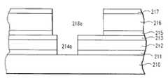
- FIG. 3( d )Another preferred embodiment of the interconnect structure of this invention is shown in FIG. 3( d ).
- This embodimentcomprises a lower substrate 210 which may contain logic elements such as transistors.
- a cap layer 211may be disposed on lower substrate 210 .
- ILD layer 212overlies cap layer 211 .
- An etch stop layer 213is disposed on ILD layer 212 .
- An adhesion promoter layer 215is disposed on etch stop layer 213 .
- ILD layer 216is deposited on adhesion promoter layer 215 , and hardmask layer 217 overlies ILD layer 216 .
- At least one via conductor 214 and line conductor 218are embedded in layers 211 , 212 , 213 , 215 , 216 and 217 as shown.
- the top surface of line conductor 218is made coplanar with the top surface of hardmask layer 217 .
- a final cap layer 219overlies line conductor 218 and hard
- ILD layers 112 , 116 , 212 and 216may be formed of any suitable dielectric material, although low-k dielectric materials are preferred.
- Suitable dielectric materialsinclude carbon-doped silicon dioxide materials; fluorinated silicate glass (FSG); organic polymeric thermoset materials, silicon oxycarbide; SiCOH dielectrics; fluorine doped silicon oxide; spin-on glasses; silsesquioxanes, including hydrogen silsesquioxane (HSQ), methyl silsesquioxane (MSQ) and mixtures or copolymers of HSQ and MSQ; benzocyclobutene (BCB)-based polymer dielectrics, and any silicon-containing low-k dielectric.
- HSQhydrogen silsesquioxane
- MSQmethyl silsesquioxane
- BCBbenzocyclobutene
- spin-on low-k films with SiCOH-type composition using silsesquioxane chemistryexamples include HOSPTM (available from Honeywell), JSR 5109 and 5108 (available from Japan Synthetic Rubber), ZirkonTM (available from Shipley Microelectronics, a division of Rohm and Haas), and porous low-k (ELk) materials (available from Applied Materials).
- HOSPTMavailable from Honeywell
- JSR 5109 and 5108available from Japan Synthetic Rubber
- ZirkonTMavailable from Shipley Microelectronics, a division of Rohm and Haas
- porous low-k (ELk) materialsavailable from Applied Materials
- carbon-doped silicon dioxide materials, or organosilanesexamples include Black DiamondTM (available from Applied Materials) and CoralTM (available from Novellus).
- An example of an HSQ materialis FOxTM (available from Dow Corning).
- Preferred dielectric materialsinclude organic polymeric thermoset materials, consisting essentially of carbon, oxygen and hydrogen, including the low-k polyarylene ether polymeric material known as SiLKTM (available from The Dow Chemical Company), and the low-k polymeric material known as FLARETM (available from Honeywell).
- SiLKTMlow-k polyarylene ether polymeric material
- FLARETMlow-k polymeric material
- via-level ILD layers 112 and 212are formed of a material having a low coefficient of thermal expansion (CTE) such as SiCOH or oxide dielectric material to improve reliability, and line-level ILD layers 116 and 216 are formed of a polymeric thermoset material having a low k such as SiLKTM. It is particularly preferred that via-level ILD layers 112 and 212 be formed of a dielectric material having a CTE of less than about 50 ppm/° C. and preferably to match the CTE of conductors 114 and 214 .
- CTEcoefficient of thermal expansion
- via-level ILD layers 112 and 212are formed of SiCOH, and line-level ILD layers 116 and 216 are formed of SiLKTM.
- via-level ILD layers 112 and 212may be formed of SiCOH, and line-level ILD layers 116 and 216 may be formed of porous SiLKTM.
- via-level ILD layers 112 and 212may be formed of porous SiCOH, and line-level ILD layers 116 and 216 may be formed of SiLKTM.
- via-level ILD layers 112 and 212may be formed of porous SiCOH, and line-level ILD layers 116 and 216 may be formed of porous SiLKTM.
- via-level ILD layers 112 and 212may be formed of porous SiCOH, and line-level ILD layers 116 and 216 may be formed of SiCOH. In yet another embodiment, via-level ILD layers 112 and 212 may be formed of SiCOH, and line-level ILD layers 116 and 216 may be formed of porous SiCOH.
- ILD layers 112 , 116 , 212 and 216may each be about 10 nm to about 1000 nm thick, but these layers are each preferably about 120 nm thick.
- the dielectric constant for ILD layers 112 , 116 , 212 and 216is preferably about 1.8 to about 3.5, and most preferably about 2.5 to about 2.9.
- the materials for ILD layers 112 , 116 , 212 and 216are porous materials, thereby further reducing the dielectric constant for these layers to the range of about 1.8 to 2.5.
- Hardmask layer 113 and etch stop layer 213may be formed of any suitable dielectric material.
- Layers 113 and 213preferably have the following characteristics: (1) a low dielectric constant (preferably less than about 7); (2) a low CMP rate relative to the liner (preferably about 1:5) and therefore acts as a CMP stop layer; (3) is hydrophilic for effective post-CMP cleaning; (4) acts as a barrier to copper diffusing into the underlying dielectric; and (5) is resistant to oxygen plasma used during resist strip operations.
- Preferred materials for layers 113 and 213include SiCH and SiNCH, such as BlokTM (available from Applied Materials, Inc.)., and have a dielectric constant of less than about 5, and preferably about 4.9.
- these layersare preferably composed of about 20 to 34 atomic % silicon, about 12 to 34 atomic % carbon, about 5 to 30 atomic % nitrogen, and about 20 to 50 atomic % hydrogen.
- the materialpreferably has the composition Si x C y N w H z , where x is about 0.2 to about 0.34, y is about 0.12 to about 0.34, w is about 0.05 to about 0.3, and z is about 0.2 to about 0.5.
- a particularly preferred composition for the SiNCH materialis about 22 to 30 atomic % silicon, about 15 to 30 atomic % carbon, about 10 to 22 atomic % nitrogen, and about 30 to 45 atomic % hydrogen.
- This particularly preferred compositionmay be expressed as Si x C y N w H z , where x is about 2.2 to about 3, y is about 1.5 to about 3, w is about 1 to about 2, and z is about 3 to about 4.5.
- the most preferred embodimentutilizes more than one via hardmask layer, wherein the bottom layer has the lowest dielectric constant and highest CMP selectivity.
- Via cap layer 115may be formed of any suitable dielectric material. Via cap layer 115 preferably has the following characteristics: (1) a low dielectric constant; (2) resistance to oxygen plasma used during resist strip operations; (3) acts as a copper barrier; and (4) has etch selectivity properties and therefore acts as an etch stop layer.
- a particularly preferred material for via cap layer 115is an amorphous nitrogenated hydrogenated silicon carbide comprising silicon, carbon, nitrogen and hydrogen (SiCNH), having a dielectric constant of less than about 5.
- Other suitable materialsinclude SiN, SiCH and SiON.
- Adhesion promoter layer 215preferably has the following characteristics: (1) low dielectric constant; (2) low moisture interaction; (3) increases oxidation resistance; and (4) RIE chemistry selectivity with respect to ILD layer 216 and via hardmask layer 213 .
- Particularly preferred materials for adhesion promoter layer 215include siloxane or SiCOH, most preferably HOSP BEStTM (available from Honeywell).
- Hardmask layers 117 and 217may be formed of any suitable dielectric material, but preferably are formed of a dielectric material having a dielectric constant less than about 5. Preferred materials for hardmask layers 117 and 217 are SiCOH and SiCH. In the most preferred embodiment, these hardmask layers have a dielectric constant less than about 3.5.
- Final cap layers 119 and 219may be formed of any suitable dielectric material, but preferably is formed of SiNCH or SiN.
- this layeris preferably composed of about 20 to 34 atomic % silicon, about 12 to 34 atomic % carbon, about 5 to 30 atomic % nitrogen, and about 20 to 50 atomic % hydrogen.
- the materialpreferably has the composition Si x C y N w H z , where x is about 0.2 to about 0.34, y is about 0.12 to about 0.34, w is about 0.05 to about 0.3, and z is about 0.2 to about 0.5.
- a particularly preferred composition for the SiNCH materialis about 22 to 30 atomic % silicon, about 15 to 30 atomic % carbon, about 10 to 22 atomic % nitrogen, and about 30 to 45 atomic % hydrogen.
- This particularly preferred compositionmay be expressed as Si x C y N w H z , where x is about 2.2 to about 3, y is about 1.5 to about 3, w is about 1 to about 2, and z is about 3 to about 4.5.
- the interconnect structure of FIG. 2( e )may be formed by a single damascene process, such as the process shown in FIGS. 2( a )– 2 ( e ).
- the processoptionally begins with deposition of cap layer 111 on substrate 110 , and is followed by deposition of ILD layer 112 on cap layer 111 , as shown in FIG. 2( a ).
- Cap layer 111 and ILD layer 112may be deposited by any suitable method. For example, if SiLKTM is used for ILD layer 112 , the resin may be applied by a spin-coating process, followed by a baking step to remove solvent and then a thermal curing step.
- Hardmask layer 113is then deposited on ILD layer 112 , as shown in FIG. 2( a ).
- Hardmask layer 113may be deposited by any suitable method, but is preferably deposited by chemical vapor deposition (CVD) directly onto ILD layer 112 when hardmask layer 113 is SiNCH.
- CVDchemical vapor deposition
- spin-on glassesmay be used for via-level hardmask layer 113 .
- An example of a preferred CVD materialis SiCH, and an example of a preferred spin-on material is HOSP BEStTM.
- a hardmask layer 113Following deposition of a hardmask layer 113 , additional sacrificial hardmask layers (not shown) may be deposited. For example, a series of hardmask layers may be deposited, such as the hardmask layers described in co-pending U.S. patent application Ser. No. 09/550,943, filed Apr. 14, 2000 and titled “Protective Hardmask for Producing Interconnect Structures,” the disclosure of which is incorporated herein by reference.
- At least one via 114 ais formed using a lithography patterning process. Via 114 a is then formed by removing hardmask layer 113 and a portion of ILD layer 112 by, for example, reactive ion etching (RIE), in areas not protected by the photoresist.
- RIEreactive ion etching
- Hardmask layer 113may assist in this etching step as follows. Hardmask layer 113 may be etched first in areas not covered by the photoresist, then the photoresist may be removed, leaving behind a patterned hardmask layer 113 matching the photoresist pattern. Then, ILD layer 112 and cap layer 111 may be etched in areas not covered by hardmask layer 113 .
- the viamay be lined with a diffusion barrier liner (not shown), and then a conductive material is deposited in via 114 a to form conductor 114 , as shown in FIG. 2( b ).
- the diffusion barrier linermay be deposited by any suitable method, such as by physical vapor deposition (PVD), chemical vapor deposition (CVD), atomic layer deposition (ALD) or ionized physical vapor deposition (I-PVD).
- the diffusion barrier linermay be a multi-layer liner constructed by depositing several refractory metals as a thin film composite.
- Conductive material 114may be deposited in via 114 a by any suitable method, such as by plating technology.
- Excess liner material and excess conductive material 114may be removed in a CMP process, in which the top surface of conductor 114 is made coplanar with the hardmask layer 113 .
- Hardmask layer 113may serve as a polish-stop layer during this CMP step, thereby protecting ILD layer 112 from damage during polishing.
- Sacrificial hardmask layers(not shown) may also be removed during this CMP step.
- FIGS. 2( a )– 2 ( b )illustrate the formation of the first interconnect level, which comprises cap layer 111 , ILD layer 112 , hardmask layer 113 and via conductor 115 .
- the formation of the second interconnect levelbegins with deposition of via cap layer 115 , ILD layer 116 and hardmask layer 117 . Additional sacrificial hardmask layers (not shown) may be deposited on primary hardmask layer 117 .
- cap layer 115is a silicon nitride film deposited by CVD. In a particularly preferred embodiment, cap layer 115 is SiCNH deposited by CVD.
- ILD layer 116is preferably formed of a material different from the material for ILD layer 112 . If ILD layer 112 is formed of a SiCOH material (preferably deposited by CVD), then ILD layer 116 is preferably formed of a polymeric thermoset material such as SiLKTM. If ILD layer 116 is a low-k polymeric material such as SiLKTM, the ILD material is typically spin-applied, given a post apply hot bake to remove solvent, and cured at elevated temperature.
- Line hardmask layer 117is preferably formed of a low-k dielectric material such as SiCOH or SiCH, and may be deposited by CVD or spin apply methods.
- a low-k dielectric materialsuch as SiCOH or SiCH
- An example of a preferred CVD materialis SiCH
- an example of a preferred spin-on materialis HOSP BEStTM.
- trench 118 ais formed using a lithography patterning and etching process which may include reactive ion etching (RIE), as shown in FIG. 2( c ).
- Trench 118 amay be lined with a diffusion barrier liner (not shown), and then a conductive material is deposited in trench 118 a to form conductor 118 , as shown in FIG. 2( d ).
- the diffusion barrier linermay be deposited by any suitable method, such as by physical vapor deposition (PVD), chemical vapor deposition (CVD), atomic layer deposition (ALD) or ionized physical vapor deposition (I-PVD).
- the diffusion barrier linermay be a multi-layer liner constructed by depositing several refractory metals as a thin film composite.
- Conductive material 118is typically the same material used for conductive via 114 , and may be deposited in trench 118 a by any suitable method, such as by plating technology. Excess liner material and excess conductive material 118 may be removed in a CMP process, in which the top surface of conductor 118 is made coplanar with the line hardmask layer 117 .
- final cap layer 119may be deposited as shown in FIG. 3( d ).
- Final cap layer 119may be formed of any suitable dielectric material, but is preferably formed of SiCNH or SiN deposited by CVD.
- the interconnect structure of this inventionmay be formed using a dual damascene method, such as the method shown in FIGS. 3( a )– 3 ( d ).
- This alternative processoptionally begins with deposition of cap layer 211 on substrate 210 , and is followed by deposition of ILD layer 212 on cap layer 211 .
- a bilayer etch stopis then constructed by first depositing etch stop layer 213 on ILD layer 212 , then depositing adhesion promoter layer 215 sequentially onto etch stop layer 213 .
- Layer 213is deposited preferably by CVD and is most preferably SiNCH.
- Adhesion promoter layer 215is deposited preferably by spin application methods and is preferably a SiCOH material, most preferably HOSP BEStTM.
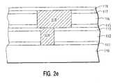
- ILD layer 216 and hardmask layer 217are deposited. Then, trench 218 a and via 214 a are formed, as shown in FIG. 3( b ), using a conventional lithography process.
- the dual damascene etch processinvolves the utilization of sacrificial hardmasks. After line level lithography is performed, the etch process transfers the line level pattern into the hardmask levels except for the non-sacrifical layer 217 . Lithography is then performed to pattern the via level. The etch process transfers the via 214 a pattern by removing the full hardmask stack (including layer 217 ) and ILD layer 216 , selectively stopping on layer 215 .
- the remaining line-level hardmask layersare etched.
- the etch processcontinues by etching the via pattern into layers 215 , 213 and 212 , and selectively stopping on layer 211 .
- the ILD layer 212is etched to further define the line.
- the cap layer 211is etched to complete the via. This final etch step also removes layer 215 in the line pattern to complete the trench 218 a.
- Via 214 a and trench 218 aare then filled with conductive material in a dual damascene process to form conductor 214 , 218 , as shown in FIG. 3( c ). Excess conductor material may be removed in a CMP process as described above.
- final cap layer 219may be deposited as shown in FIG. 3( d ).
- Final cap layer 219may be formed of any suitable dielectric material, but is preferably formed of SiCNH or SiN deposited by CVD.
- the interconnect structure of this inventionmay be formed using a simplified dual damascene method as follows.
- the properties of ILD layer 212may be adjusted for selectivity in the RIE patterning step, and the RIE step chemistry may be adjusted by, for example, making layers 216 and 212 dissimilar materials, thereby permitting embedded layers 213 and 215 to be omitted from the structure.
- CF 4may be used to etch SiCOH materials and N 2 /H 2 may be used to etch polymeric materials such as SiLK.
Landscapes
- Engineering & Computer Science (AREA)
- Physics & Mathematics (AREA)
- Condensed Matter Physics & Semiconductors (AREA)
- General Physics & Mathematics (AREA)
- Computer Hardware Design (AREA)
- Microelectronics & Electronic Packaging (AREA)
- Power Engineering (AREA)
- Manufacturing & Machinery (AREA)
- Internal Circuitry In Semiconductor Integrated Circuit Devices (AREA)
- Formation Of Insulating Films (AREA)
Abstract
Description
Claims (28)
Priority Applications (1)
| Application Number | Priority Date | Filing Date | Title |
|---|---|---|---|
| US10/901,868US7135398B2 (en) | 2002-11-14 | 2004-07-29 | Reliable low-k interconnect structure with hybrid dielectric |
Applications Claiming Priority (2)
| Application Number | Priority Date | Filing Date | Title |
|---|---|---|---|
| US10/294,139US6917108B2 (en) | 2002-11-14 | 2002-11-14 | Reliable low-k interconnect structure with hybrid dielectric |
| US10/901,868US7135398B2 (en) | 2002-11-14 | 2004-07-29 | Reliable low-k interconnect structure with hybrid dielectric |
Related Parent Applications (1)
| Application Number | Title | Priority Date | Filing Date |
|---|---|---|---|
| US10/294,139DivisionUS6917108B2 (en) | 2002-11-14 | 2002-11-14 | Reliable low-k interconnect structure with hybrid dielectric |
Publications (2)
| Publication Number | Publication Date |
|---|---|
| US20050023693A1 US20050023693A1 (en) | 2005-02-03 |
| US7135398B2true US7135398B2 (en) | 2006-11-14 |
Family
ID=32296906
Family Applications (2)
| Application Number | Title | Priority Date | Filing Date |
|---|---|---|---|
| US10/294,139Expired - LifetimeUS6917108B2 (en) | 2002-11-14 | 2002-11-14 | Reliable low-k interconnect structure with hybrid dielectric |
| US10/901,868Expired - LifetimeUS7135398B2 (en) | 2002-11-14 | 2004-07-29 | Reliable low-k interconnect structure with hybrid dielectric |
Family Applications Before (1)
| Application Number | Title | Priority Date | Filing Date |
|---|---|---|---|
| US10/294,139Expired - LifetimeUS6917108B2 (en) | 2002-11-14 | 2002-11-14 | Reliable low-k interconnect structure with hybrid dielectric |
Country Status (8)
| Country | Link |
|---|---|
| US (2) | US6917108B2 (en) |
| EP (1) | EP1561241A1 (en) |
| JP (2) | JP2006506806A (en) |
| KR (1) | KR100773003B1 (en) |
| CN (1) | CN1314101C (en) |
| AU (1) | AU2003279460A1 (en) |
| TW (1) | TWI234231B (en) |
| WO (1) | WO2004044978A1 (en) |
Cited By (9)
| Publication number | Priority date | Publication date | Assignee | Title |
|---|---|---|---|---|
| US20070155186A1 (en)* | 2005-11-22 | 2007-07-05 | International Business Machines Corporation | OPTIMIZED SiCN CAPPING LAYER |
| US20080272493A1 (en)* | 2007-05-02 | 2008-11-06 | Taiwan Semiconductor Manufacturing Co., Ltd. | Semiconductor device |
| US20090001592A1 (en)* | 2007-06-29 | 2009-01-01 | International Business Machines Corporation | Metal interconnect forming methods and ic chip including metal interconnect |
| US20090176367A1 (en)* | 2008-01-08 | 2009-07-09 | Heidi Baks | OPTIMIZED SiCN CAPPING LAYER |
| US20090179306A1 (en)* | 2008-01-10 | 2009-07-16 | International Business Machines Corporation | ADVANCED LOW k CAP FILM FORMATION PROCESS FOR NANO ELECTRONIC DEVICES |
| US20090315186A1 (en)* | 2008-06-20 | 2009-12-24 | Nec Electronics Corporation | Method for manufacturing semiconductor device and the semiconductor device |
| US20100248988A1 (en)* | 2005-11-03 | 2010-09-30 | Redpoint Bio Corporation | High Throughput Screening Assay for the TRPM5 Ion Channel |
| US20110115088A1 (en)* | 2009-11-19 | 2011-05-19 | Taiwan Semiconductor Manufacturing Co., Ltd. | Interconnect with flexible dielectric layer |
| US20220108922A1 (en)* | 2019-11-08 | 2022-04-07 | International Business Machines Corporation | Fully aligned top vias |
Families Citing this family (40)
| Publication number | Priority date | Publication date | Assignee | Title |
|---|---|---|---|---|
| US7425346B2 (en)* | 2001-02-26 | 2008-09-16 | Dielectric Systems, Inc. | Method for making hybrid dielectric film |
| JP2004146798A (en)* | 2002-09-30 | 2004-05-20 | Sanyo Electric Co Ltd | Semiconductor device and manufacturing method therefor |
| JP3898133B2 (en)* | 2003-01-14 | 2007-03-28 | Necエレクトロニクス株式会社 | A method of forming a SiCHN film. |
| JP3715626B2 (en)* | 2003-01-17 | 2005-11-09 | 株式会社東芝 | Semiconductor device manufacturing method and semiconductor device |
| JP4086673B2 (en)* | 2003-02-04 | 2008-05-14 | Necエレクトロニクス株式会社 | Semiconductor device and manufacturing method thereof |
| US7081673B2 (en)* | 2003-04-17 | 2006-07-25 | International Business Machines Corporation | Multilayered cap barrier in microelectronic interconnect structures |
| US6919636B1 (en) | 2003-07-31 | 2005-07-19 | Advanced Micro Devices, Inc. | Interconnects with a dielectric sealant layer |
| US7199046B2 (en)* | 2003-11-14 | 2007-04-03 | Tokyo Electron Ltd. | Structure comprising tunable anti-reflective coating and method of forming thereof |
| US20050130407A1 (en)* | 2003-12-12 | 2005-06-16 | Jui-Neng Tu | Dual damascene process for forming a multi-layer low-k dielectric interconnect |
| US7224068B2 (en)* | 2004-04-06 | 2007-05-29 | Taiwan Semiconductor Manufacturing Company, Ltd. | Stable metal structure with tungsten plug |
| US20060012014A1 (en)* | 2004-07-15 | 2006-01-19 | International Business Machines Corporation | Reliability of low-k dielectric devices with energy dissipative layer |
| US20060027924A1 (en)* | 2004-08-03 | 2006-02-09 | Taiwan Semiconductor Manufacturing Co., Ltd. | Metallization layers for crack prevention and reduced capacitance |
| US6974772B1 (en)* | 2004-08-19 | 2005-12-13 | Intel Corporation | Integrated low-k hard mask |
| US7348672B2 (en)* | 2005-07-07 | 2008-03-25 | Taiwan Semiconductor Manufacturing Co., Ltd. | Interconnects with improved reliability |
| US7341941B2 (en)* | 2005-08-19 | 2008-03-11 | Texas Instruments Incorporated | Methods to facilitate etch uniformity and selectivity |
| US20070059922A1 (en)* | 2005-09-13 | 2007-03-15 | International Business Machines Corporation | Post-etch removal of fluorocarbon-based residues from a hybrid dielectric structure |
| US7394154B2 (en)* | 2005-09-13 | 2008-07-01 | International Business Machines Corporation | Embedded barrier for dielectric encapsulation |
| US7338893B2 (en)* | 2005-11-23 | 2008-03-04 | Texas Instruments Incorporated | Integration of pore sealing liner into dual-damascene methods and devices |
| US7358182B2 (en)* | 2005-12-22 | 2008-04-15 | International Business Machines Corporation | Method of forming an interconnect structure |
| US20070152332A1 (en)* | 2006-01-04 | 2007-07-05 | International Business Machines Corporation | Single or dual damascene via level wirings and/or devices, and methods of fabricating same |
| US7473636B2 (en)* | 2006-01-12 | 2009-01-06 | International Business Machines Corporation | Method to improve time dependent dielectric breakdown |
| US20070278682A1 (en)* | 2006-05-31 | 2007-12-06 | Chung-Chi Ko | Self-assembled mono-layer liner for cu/porous low-k interconnections |
| US7727885B2 (en)* | 2006-08-29 | 2010-06-01 | Texas Instruments Incorporated | Reduction of punch-thru defects in damascene processing |
| US7466027B2 (en)* | 2006-09-13 | 2008-12-16 | Taiwan Semiconductor Manufacturing Co., Ltd. | Interconnect structures with surfaces roughness improving liner and methods for fabricating the same |
| US7749894B2 (en)* | 2006-11-09 | 2010-07-06 | Chartered Semiconductor Manufacturing Ltd. | Integrated circuit processing system |
| US7723226B2 (en)* | 2007-01-17 | 2010-05-25 | Taiwan Semiconductor Manufacturing Company, Ltd. | Interconnects containing bilayer porous low-k dielectrics using different porogen to structure former ratio |
| US7947565B2 (en) | 2007-02-07 | 2011-05-24 | United Microelectronics Corp. | Forming method of porous low-k layer and interconnect process |
| US20090032491A1 (en)* | 2007-08-03 | 2009-02-05 | International Business Machines Corporation | Conductive element forming using sacrificial layer patterned to form dielectric layer |
| US20090269507A1 (en) | 2008-04-29 | 2009-10-29 | Sang-Ho Yu | Selective cobalt deposition on copper surfaces |
| US7863176B2 (en)* | 2008-05-13 | 2011-01-04 | Micron Technology, Inc. | Low-resistance interconnects and methods of making same |
| US8189292B2 (en)* | 2008-12-24 | 2012-05-29 | Hitachi Global Storage Technologies Netherlands B.V. | Method for manufacturing a magnetic write head having a write pole with a trailing edge taper using a Rieable hard mask |
| US8889235B2 (en)* | 2009-05-13 | 2014-11-18 | Air Products And Chemicals, Inc. | Dielectric barrier deposition using nitrogen containing precursor |
| JP2012190900A (en)* | 2011-03-09 | 2012-10-04 | Sony Corp | Semiconductor device and method of manufacturing the same |
| US8461683B2 (en)* | 2011-04-01 | 2013-06-11 | Intel Corporation | Self-forming, self-aligned barriers for back-end interconnects and methods of making same |
| US8980740B2 (en) | 2013-03-06 | 2015-03-17 | Globalfoundries Inc. | Barrier layer conformality in copper interconnects |
| US9385086B2 (en)* | 2013-12-10 | 2016-07-05 | Taiwan Semiconductor Manufacturing Co., Ltd. | Bi-layer hard mask for robust metallization profile |
| US9905456B1 (en)* | 2016-09-26 | 2018-02-27 | Taiwan Semiconductor Manufacturing Co., Ltd. | Semiconductor device and manufacturing method thereof |
| US10256191B2 (en) | 2017-01-23 | 2019-04-09 | International Business Machines Corporation | Hybrid dielectric scheme for varying liner thickness and manganese concentration |
| US11244854B2 (en) | 2020-03-24 | 2022-02-08 | International Business Machines Corporation | Dual damascene fully aligned via in interconnects |
| KR20220101377A (en) | 2021-01-11 | 2022-07-19 | 삼성전자주식회사 | Semiconductor device and method for fabricating the same |
Citations (38)
| Publication number | Priority date | Publication date | Assignee | Title |
|---|---|---|---|---|
| US6159842A (en) | 1999-01-11 | 2000-12-12 | Taiwan Semiconductor Manufacturing Company | Method for fabricating a hybrid low-dielectric-constant intermetal dielectric (IMD) layer with improved reliability for multilevel interconnections |
| US6187663B1 (en) | 1999-01-19 | 2001-02-13 | Taiwan Semiconductor Manufacturing Company | Method of optimizing device performance via use of copper damascene structures, and HSQ/FSG, hybrid low dielectric constant materials |
| US6245662B1 (en) | 1998-07-23 | 2001-06-12 | Applied Materials, Inc. | Method of producing an interconnect structure for an integrated circuit |
| US6265780B1 (en) | 1998-12-01 | 2001-07-24 | United Microelectronics Corp. | Dual damascene structure for the wiring-line structures of multi-level interconnects in integrated circuit |
| US6265779B1 (en) | 1998-08-11 | 2001-07-24 | International Business Machines Corporation | Method and material for integration of fuorine-containing low-k dielectrics |
| US20020024150A1 (en) | 2000-08-31 | 2002-02-28 | Farrar Paul A. | Etch stop in damascene interconnect structure and method of making |
| US6358842B1 (en) | 2000-08-07 | 2002-03-19 | Chartered Semiconductor Manufacturing Ltd. | Method to form damascene interconnects with sidewall passivation to protect organic dielectrics |
| US6362091B1 (en) | 2000-03-14 | 2002-03-26 | Intel Corporation | Method for making a semiconductor device having a low-k dielectric layer |
| US20020048931A1 (en) | 2000-08-28 | 2002-04-25 | Farrar Paul A. | Damascene structure and method of making |
| US6380091B1 (en) | 1999-01-27 | 2002-04-30 | Advanced Micro Devices, Inc. | Dual damascene arrangement for metal interconnection with oxide dielectric layer and low K dielectric constant layer |
| US20020052125A1 (en) | 2000-08-21 | 2002-05-02 | Shaffer Edward O. | Organosilicate resins as hardmasks for organic polymer dielectrics in fabrication of microelectronic devices |
| US6383920B1 (en) | 2001-01-10 | 2002-05-07 | International Business Machines Corporation | Process of enclosing via for improved reliability in dual damascene interconnects |
| US6391757B1 (en) | 2001-06-06 | 2002-05-21 | United Microelectronics Corp. | Dual damascene process |
| US6406994B1 (en) | 1999-12-03 | 2002-06-18 | Chartered Semiconductor Manufacturing Ltd. | Triple-layered low dielectric constant dielectric dual damascene approach |
| US6437443B1 (en)* | 1999-05-26 | 2002-08-20 | International Business Machines Corporation | Multiphase low dielectric constant material and method of deposition |
| US20020117737A1 (en) | 2001-02-28 | 2002-08-29 | International Business Corporation | Interconnect structure with precise conductor resistance and method to form same |
| US20020117754A1 (en) | 2001-02-28 | 2002-08-29 | International Business Machines Corporation | Hybrid low-k interconnect structure comprised of 2 spin-on dielectric materials |
| US20020117760A1 (en) | 2001-02-28 | 2002-08-29 | International Business Corporation | Low-k interconnect structure comprised of a multilayer of spin-on porous dielectrics |
| US6451712B1 (en)* | 2000-12-18 | 2002-09-17 | International Business Machines Corporation | Method for forming a porous dielectric material layer in a semiconductor device and device formed |
| US20020130416A1 (en) | 1999-06-09 | 2002-09-19 | Shi-Qing Wang | Integrated circuits with multiple low dielectric-constant inter-metal dielectrics |
| US20020137323A1 (en) | 2001-01-03 | 2002-09-26 | Loboda Mark Jon | Metal ion diffusion barrier layers |
| US6472306B1 (en)* | 2000-09-05 | 2002-10-29 | Industrial Technology Research Institute | Method of forming a dual damascene opening using CVD Low-K material and spin-on-polymer |
| US20020164889A1 (en) | 2001-05-02 | 2002-11-07 | Cheng-Yuan Tsai | Method for improving adhesion of low k materials with adjacent layer |
| US20020164865A1 (en) | 2000-05-25 | 2002-11-07 | Hitachi, Ltd. | Semiconductor device and manufacturing method thereof |
| US6486557B1 (en) | 2000-02-29 | 2002-11-26 | International Business Machines Corporation | Hybrid dielectric structure for improving the stiffness of back end of the line structures |
| US20030001273A1 (en) | 2001-06-28 | 2003-01-02 | Steiner Kurt G. | Structure and method for isolating porous low-k dielectric films |
| US20030089988A1 (en) | 2001-11-14 | 2003-05-15 | Mitsubishi Denki Kabushiki Kaisha | Semiconductor device and method of manufacturing the same |
| US6573604B1 (en) | 2002-04-26 | 2003-06-03 | Kabushiki Kaisha Toshiba | Semiconductor device carrying memory and logic circuit on a chip and method of manufacturing the same |
| US20030134499A1 (en)* | 2002-01-15 | 2003-07-17 | International Business Machines Corporation | Bilayer HDP CVD / PE CVD cap in advanced BEOL interconnect structures and method thereof |
| US20030176058A1 (en)* | 2002-03-18 | 2003-09-18 | Applies Materials, Inc. | Method of forming a dual damascene structure using an amorphous silicon hard mask |
| US6624053B2 (en)* | 1999-12-13 | 2003-09-23 | Stmicroelectronics S.A. | Damascene-type interconnection structure and its production process |
| US20030183939A1 (en) | 2002-03-28 | 2003-10-02 | Fujitsu Limited | Semiconductor device with copper wirings |
| US6677231B1 (en)* | 2000-11-14 | 2004-01-13 | United Microelectronics Corp. | Method for increasing adhesion ability of dielectric material in semiconductor |
| US6764774B2 (en)* | 2002-06-19 | 2004-07-20 | International Business Machines Corporation | Structures with improved adhesion to Si and C containing dielectrics and method for preparing the same |
| US6828229B2 (en)* | 2001-05-10 | 2004-12-07 | Samsung Electronics Co., Ltd. | Method of manufacturing interconnection line in semiconductor device |
| US6867125B2 (en)* | 2002-09-26 | 2005-03-15 | Intel Corporation | Creating air gap in multi-level metal interconnects using electron beam to remove sacrificial material |
| US6879046B2 (en)* | 2001-06-28 | 2005-04-12 | Agere Systems Inc. | Split barrier layer including nitrogen-containing portion and oxygen-containing portion |
| US7023093B2 (en)* | 2002-10-24 | 2006-04-04 | International Business Machines Corporation | Very low effective dielectric constant interconnect Structures and methods for fabricating the same |
Family Cites Families (8)
| Publication number | Priority date | Publication date | Assignee | Title |
|---|---|---|---|---|
| JP2000150516A (en) | 1998-09-02 | 2000-05-30 | Tokyo Electron Ltd | Method for manufacturing semiconductor device |
| JP4173307B2 (en)* | 1999-06-24 | 2008-10-29 | 株式会社ルネサステクノロジ | Manufacturing method of semiconductor integrated circuit |
| US6319814B1 (en)* | 1999-10-12 | 2001-11-20 | United Microelectronics Corp. | Method of fabricating dual damascene |
| US6440878B1 (en)* | 2000-04-03 | 2002-08-27 | Sharp Laboratories Of America, Inc. | Method to enhance the adhesion of silicon nitride to low-k fluorinated amorphous carbon using a silicon carbide adhesion promoter layer |
| US6380084B1 (en)* | 2000-10-02 | 2002-04-30 | Chartered Semiconductor Manufacturing Inc. | Method to form high performance copper damascene interconnects by de-coupling via and metal line filling |
| EP1352107A2 (en)* | 2000-10-25 | 2003-10-15 | International Business Machines Corporation | An ultralow dielectric constant material as an intralevel or interlevel dielectric in a semiconductor device, a method for fabricating the same, and an electronic device containing the same |
| JP2002164428A (en)* | 2000-11-29 | 2002-06-07 | Hitachi Ltd | Semiconductor device and manufacturing method thereof |
| CA2442030A1 (en) | 2001-04-16 | 2002-10-24 | Brian Daniels | Layered stacks and methods of production thereof |
- 2002
- 2002-11-14USUS10/294,139patent/US6917108B2/ennot_activeExpired - Lifetime
- 2003
- 2003-10-30TWTW092130322Apatent/TWI234231B/ennot_activeIP Right Cessation
- 2003-11-07JPJP2004550790Apatent/JP2006506806A/enactivePending
- 2003-11-07EPEP03772408Apatent/EP1561241A1/ennot_activeWithdrawn
- 2003-11-07CNCNB2003801033040Apatent/CN1314101C/ennot_activeExpired - Lifetime
- 2003-11-07WOPCT/GB2003/004814patent/WO2004044978A1/enactiveApplication Filing
- 2003-11-07KRKR1020057008490Apatent/KR100773003B1/ennot_activeExpired - Fee Related
- 2003-11-07AUAU2003279460Apatent/AU2003279460A1/ennot_activeAbandoned
- 2004
- 2004-07-29USUS10/901,868patent/US7135398B2/ennot_activeExpired - Lifetime
- 2010
- 2010-11-04JPJP2010247790Apatent/JP2011061228A/enactivePending
Patent Citations (42)
| Publication number | Priority date | Publication date | Assignee | Title |
|---|---|---|---|---|
| US6245662B1 (en) | 1998-07-23 | 2001-06-12 | Applied Materials, Inc. | Method of producing an interconnect structure for an integrated circuit |
| US20020048929A1 (en) | 1998-07-23 | 2002-04-25 | Applied Materials, Inc. | Method of producing an interconnect structure for an integrated circuit |
| US6265779B1 (en) | 1998-08-11 | 2001-07-24 | International Business Machines Corporation | Method and material for integration of fuorine-containing low-k dielectrics |
| US6265780B1 (en) | 1998-12-01 | 2001-07-24 | United Microelectronics Corp. | Dual damascene structure for the wiring-line structures of multi-level interconnects in integrated circuit |
| US20020130417A1 (en) | 1998-12-01 | 2002-09-19 | Tri-Rung Yew | Dual damascene structure for the wiring-line structures of multi-level interconnects in integrated circuit |
| US6159842A (en) | 1999-01-11 | 2000-12-12 | Taiwan Semiconductor Manufacturing Company | Method for fabricating a hybrid low-dielectric-constant intermetal dielectric (IMD) layer with improved reliability for multilevel interconnections |
| US6187663B1 (en) | 1999-01-19 | 2001-02-13 | Taiwan Semiconductor Manufacturing Company | Method of optimizing device performance via use of copper damascene structures, and HSQ/FSG, hybrid low dielectric constant materials |
| US6380091B1 (en) | 1999-01-27 | 2002-04-30 | Advanced Micro Devices, Inc. | Dual damascene arrangement for metal interconnection with oxide dielectric layer and low K dielectric constant layer |
| US6437443B1 (en)* | 1999-05-26 | 2002-08-20 | International Business Machines Corporation | Multiphase low dielectric constant material and method of deposition |
| US20020130416A1 (en) | 1999-06-09 | 2002-09-19 | Shi-Qing Wang | Integrated circuits with multiple low dielectric-constant inter-metal dielectrics |
| US6406994B1 (en) | 1999-12-03 | 2002-06-18 | Chartered Semiconductor Manufacturing Ltd. | Triple-layered low dielectric constant dielectric dual damascene approach |
| US6624053B2 (en)* | 1999-12-13 | 2003-09-23 | Stmicroelectronics S.A. | Damascene-type interconnection structure and its production process |
| US6486557B1 (en) | 2000-02-29 | 2002-11-26 | International Business Machines Corporation | Hybrid dielectric structure for improving the stiffness of back end of the line structures |
| US6362091B1 (en) | 2000-03-14 | 2002-03-26 | Intel Corporation | Method for making a semiconductor device having a low-k dielectric layer |
| US20020164865A1 (en) | 2000-05-25 | 2002-11-07 | Hitachi, Ltd. | Semiconductor device and manufacturing method thereof |
| US6358842B1 (en) | 2000-08-07 | 2002-03-19 | Chartered Semiconductor Manufacturing Ltd. | Method to form damascene interconnects with sidewall passivation to protect organic dielectrics |
| US20020052125A1 (en) | 2000-08-21 | 2002-05-02 | Shaffer Edward O. | Organosilicate resins as hardmasks for organic polymer dielectrics in fabrication of microelectronic devices |
| US20020048931A1 (en) | 2000-08-28 | 2002-04-25 | Farrar Paul A. | Damascene structure and method of making |
| US6395632B1 (en) | 2000-08-31 | 2002-05-28 | Micron Technology, Inc. | Etch stop in damascene interconnect structure and method of making |
| US20020024150A1 (en) | 2000-08-31 | 2002-02-28 | Farrar Paul A. | Etch stop in damascene interconnect structure and method of making |
| US6472306B1 (en)* | 2000-09-05 | 2002-10-29 | Industrial Technology Research Institute | Method of forming a dual damascene opening using CVD Low-K material and spin-on-polymer |
| US6677231B1 (en)* | 2000-11-14 | 2004-01-13 | United Microelectronics Corp. | Method for increasing adhesion ability of dielectric material in semiconductor |
| US6451712B1 (en)* | 2000-12-18 | 2002-09-17 | International Business Machines Corporation | Method for forming a porous dielectric material layer in a semiconductor device and device formed |
| US20020137323A1 (en) | 2001-01-03 | 2002-09-26 | Loboda Mark Jon | Metal ion diffusion barrier layers |
| US6383920B1 (en) | 2001-01-10 | 2002-05-07 | International Business Machines Corporation | Process of enclosing via for improved reliability in dual damascene interconnects |
| US20020117737A1 (en) | 2001-02-28 | 2002-08-29 | International Business Corporation | Interconnect structure with precise conductor resistance and method to form same |
| US20020117754A1 (en) | 2001-02-28 | 2002-08-29 | International Business Machines Corporation | Hybrid low-k interconnect structure comprised of 2 spin-on dielectric materials |
| US20020117760A1 (en) | 2001-02-28 | 2002-08-29 | International Business Corporation | Low-k interconnect structure comprised of a multilayer of spin-on porous dielectrics |
| US20020164889A1 (en) | 2001-05-02 | 2002-11-07 | Cheng-Yuan Tsai | Method for improving adhesion of low k materials with adjacent layer |
| US6828229B2 (en)* | 2001-05-10 | 2004-12-07 | Samsung Electronics Co., Ltd. | Method of manufacturing interconnection line in semiconductor device |
| US6391757B1 (en) | 2001-06-06 | 2002-05-21 | United Microelectronics Corp. | Dual damascene process |
| US6798043B2 (en)* | 2001-06-28 | 2004-09-28 | Agere Systems, Inc. | Structure and method for isolating porous low-k dielectric films |
| US20030001273A1 (en) | 2001-06-28 | 2003-01-02 | Steiner Kurt G. | Structure and method for isolating porous low-k dielectric films |
| US6879046B2 (en)* | 2001-06-28 | 2005-04-12 | Agere Systems Inc. | Split barrier layer including nitrogen-containing portion and oxygen-containing portion |
| US20030089988A1 (en) | 2001-11-14 | 2003-05-15 | Mitsubishi Denki Kabushiki Kaisha | Semiconductor device and method of manufacturing the same |
| US20030134499A1 (en)* | 2002-01-15 | 2003-07-17 | International Business Machines Corporation | Bilayer HDP CVD / PE CVD cap in advanced BEOL interconnect structures and method thereof |
| US20030176058A1 (en)* | 2002-03-18 | 2003-09-18 | Applies Materials, Inc. | Method of forming a dual damascene structure using an amorphous silicon hard mask |
| US20030183939A1 (en) | 2002-03-28 | 2003-10-02 | Fujitsu Limited | Semiconductor device with copper wirings |
| US6573604B1 (en) | 2002-04-26 | 2003-06-03 | Kabushiki Kaisha Toshiba | Semiconductor device carrying memory and logic circuit on a chip and method of manufacturing the same |
| US6764774B2 (en)* | 2002-06-19 | 2004-07-20 | International Business Machines Corporation | Structures with improved adhesion to Si and C containing dielectrics and method for preparing the same |
| US6867125B2 (en)* | 2002-09-26 | 2005-03-15 | Intel Corporation | Creating air gap in multi-level metal interconnects using electron beam to remove sacrificial material |
| US7023093B2 (en)* | 2002-10-24 | 2006-04-04 | International Business Machines Corporation | Very low effective dielectric constant interconnect Structures and methods for fabricating the same |
Non-Patent Citations (7)
| Title |
|---|
| "A High Performance 0.13 um Copper DEOL Technology with Low-K Dielectric" R.D. Goldblatt, B. Agarwala, M.B. Anand, E.P. Barth, G.A. Biery, Z.G. Chen, S. Cohen, J.B. Connolly, A. Cowley, T. Dalton, S.K. Das, C.R. Davis, A. Deutsch, C. DeWan, D.C. Edelstein, P.A. Emmi, C.G. Faltermeir, J.A. Fitzsimmons, J. Hedrick, J.E. Heidenreich, C.K. Hu, J.P. Hummel, P. Jones, E. Kaltalioglu, B.E. Kastenmeier, M. Krishnan, W.F. Landers, E. Liniger, J. Kiu, N.E. Lustig, S. Malhotra, D.K. Manger, V. McGahay, R. Mih, H.A. Nye, S. Purushothaman, H.A. Rathore, S.C. Seo, T. M. Shaw, A. H. Simon, T.A. Spooner, M. Stetter, R.A. Wachnik, J. G. Ryan, IBM Semiconductor Research and Development Center and Infineon Technologies, Inc. 2000 IEEE. |
| "A. 0.11 CMOS Technology with Copper and Very-low-K Interconnects for High Performance System-On-A-Chip Cores"Y. Takao, H. Kudo, J. Mitani, Y. Kotani, S. Yamagushi, K. Yoshie, and M. Kawano, Manufacturing TechnologyDevelopment Division, Fujitsu Limited; 2000 IEEE, IEDM 00-559. |
| "Robust 130nm-Node Cu Dual Damascene Technology with Low-K Barrier SiCN", H, Aoki, K. Torii, T. Oshima, J.Noguchi, U. Tanaka, H. Yamaguchi, T. Saito, N. Miura, T. Tamaru, N. Konishi, S. Uno, S. Morita, T. Fujii, and K. Hinode,Device Development Center Hitachi, Ltd. 2001 IEEE, 76-IEDM 01. |
| Hasegawa T, et al. "Copper Dual Damascene Interconnects with Low-K (KOFF 3.0) Dielectrics Using Flaretm and an Organo-Silicate Hard Mask" International Electron Devices Meeting 1999 IEDM. Technical Digest. Washington DC, Dec. 5-8, 1999 New York, NY IEEE US, Aug. 1, 2000 pp. 623-626. |
| Hongring Yang et al.: Multilevel Damascene Interconnection in Integration of MOCVD Cu and Low-k Fluorinated Amorphous Carbon; Proceedings of the Symposium on Low-Dielectric constant Materials V, San Francisco, Apr. 5-8, 1999; Mat. Res. Soc. Symp. Proc. 565, p. 129-134, XP008035921. |
| M. Tada et al., "Copper Dual Damascene Interconnects in Porous Organosilica Film with Organic Hard-mask and Etch-Stop Layers For 70nm-Node ULSIs" Proc. IEEE Int. Interconnect Conference 2002 Burlingame USA May 3-6, 2002 pp. 12-14. |
| T. Usami, et al. "Stopper-less Hybrid Low-K/Cu DD Structure Fabrication Combined with Low-K CMP" Proc. IEEE Int. Interconnect Conf. 2002, burligame USA May 3-5, 2002 pp. 250-252. |
Cited By (18)
| Publication number | Priority date | Publication date | Assignee | Title |
|---|---|---|---|---|
| US20100248988A1 (en)* | 2005-11-03 | 2010-09-30 | Redpoint Bio Corporation | High Throughput Screening Assay for the TRPM5 Ion Channel |
| US20070155186A1 (en)* | 2005-11-22 | 2007-07-05 | International Business Machines Corporation | OPTIMIZED SiCN CAPPING LAYER |
| US20080272493A1 (en)* | 2007-05-02 | 2008-11-06 | Taiwan Semiconductor Manufacturing Co., Ltd. | Semiconductor device |
| US7485949B2 (en)* | 2007-05-02 | 2009-02-03 | Taiwan Semiconductor Manufacturing Co., Ltd. | Semiconductor device |
| US7718525B2 (en) | 2007-06-29 | 2010-05-18 | International Business Machines Corporation | Metal interconnect forming methods and IC chip including metal interconnect |
| US20090001592A1 (en)* | 2007-06-29 | 2009-01-01 | International Business Machines Corporation | Metal interconnect forming methods and ic chip including metal interconnect |
| US7851919B2 (en) | 2007-06-29 | 2010-12-14 | International Business Machines Corporation | Metal interconnect and IC chip including metal interconnect |
| US20090176367A1 (en)* | 2008-01-08 | 2009-07-09 | Heidi Baks | OPTIMIZED SiCN CAPPING LAYER |
| US20090179306A1 (en)* | 2008-01-10 | 2009-07-16 | International Business Machines Corporation | ADVANCED LOW k CAP FILM FORMATION PROCESS FOR NANO ELECTRONIC DEVICES |
| US8212337B2 (en) | 2008-01-10 | 2012-07-03 | International Business Machines Corporation | Advanced low k cap film formation process for nano electronic devices |
| US8664109B2 (en) | 2008-01-10 | 2014-03-04 | International Business Machines Corporation | Advanced low k cap film formation process for nano electronic devices |
| US9040411B2 (en) | 2008-01-10 | 2015-05-26 | International Business Machines Corporation | Advanced low k cap film formation process for nano electronic devices |
| US20090315186A1 (en)* | 2008-06-20 | 2009-12-24 | Nec Electronics Corporation | Method for manufacturing semiconductor device and the semiconductor device |
| US8008777B2 (en)* | 2008-06-20 | 2011-08-30 | Renesas Electronics Corporation | Method for manufacturing semiconductor device and the semiconductor device |
| US20110115088A1 (en)* | 2009-11-19 | 2011-05-19 | Taiwan Semiconductor Manufacturing Co., Ltd. | Interconnect with flexible dielectric layer |
| US8836127B2 (en)* | 2009-11-19 | 2014-09-16 | Taiwan Semiconductor Manufacturing Co., Ltd. | Interconnect with flexible dielectric layer |
| US20220108922A1 (en)* | 2019-11-08 | 2022-04-07 | International Business Machines Corporation | Fully aligned top vias |
| US11854884B2 (en)* | 2019-11-08 | 2023-12-26 | International Business Machines Corporation | Fully aligned top vias |
Also Published As
| Publication number | Publication date |
|---|---|
| TW200419714A (en) | 2004-10-01 |
| JP2011061228A (en) | 2011-03-24 |
| CN1711635A (en) | 2005-12-21 |
| EP1561241A1 (en) | 2005-08-10 |
| JP2006506806A (en) | 2006-02-23 |
| KR20050074996A (en) | 2005-07-19 |
| US6917108B2 (en) | 2005-07-12 |
| KR100773003B1 (en) | 2007-11-05 |
| CN1314101C (en) | 2007-05-02 |
| WO2004044978A1 (en) | 2004-05-27 |
| AU2003279460A1 (en) | 2004-06-03 |
| US20040094839A1 (en) | 2004-05-20 |
| TWI234231B (en) | 2005-06-11 |
| US20050023693A1 (en) | 2005-02-03 |
Similar Documents
| Publication | Publication Date | Title |
|---|---|---|
| US7135398B2 (en) | Reliable low-k interconnect structure with hybrid dielectric | |
| US6914320B2 (en) | Bilayer HDP CVD/PE CVD cap in advanced BEOL interconnect structures and method thereof | |
| US6939797B2 (en) | Advanced BEOL interconnect structures with low-k PE CVD cap layer and method thereof | |
| US8053901B2 (en) | Sacrificial inorganic polymer intermetal dielectric damascene wire and via liner | |
| US6764774B2 (en) | Structures with improved adhesion to Si and C containing dielectrics and method for preparing the same | |
| JP2004146800A (en) | Manufacturing method and structure of interconnection structure | |
| US6927113B1 (en) | Semiconductor component and method of manufacture | |
| US20030134495A1 (en) | Integration scheme for advanced BEOL metallization including low-k cap layer and method thereof | |
| US20150318207A1 (en) | Back-end-of-line (beol) interconnect structure | |
| US6451687B1 (en) | Intermetal dielectric layer for integrated circuits | |
| US7282441B2 (en) | De-fluorination after via etch to preserve passivation | |
| US20080251929A1 (en) | Semiconductor Device and Semiconductor Device Manufacturing Method | |
| US6548901B1 (en) | Cu/low-k BEOL with nonconcurrent hybrid dielectric interface |
Legal Events
| Date | Code | Title | Description |
|---|---|---|---|
| FEPP | Fee payment procedure | Free format text:PAYOR NUMBER ASSIGNED (ORIGINAL EVENT CODE: ASPN); ENTITY STATUS OF PATENT OWNER: LARGE ENTITY | |
| STCF | Information on status: patent grant | Free format text:PATENTED CASE | |
| FPAY | Fee payment | Year of fee payment:4 | |
| REMI | Maintenance fee reminder mailed | ||
| FPAY | Fee payment | Year of fee payment:8 | |
| SULP | Surcharge for late payment | Year of fee payment:7 | |
| AS | Assignment | Owner name:GLOBALFOUNDRIES U.S. 2 LLC, NEW YORK Free format text:ASSIGNMENT OF ASSIGNORS INTEREST;ASSIGNOR:INTERNATIONAL BUSINESS MACHINES CORPORATION;REEL/FRAME:036550/0001 Effective date:20150629 | |
| AS | Assignment | Owner name:GLOBALFOUNDRIES INC., CAYMAN ISLANDS Free format text:ASSIGNMENT OF ASSIGNORS INTEREST;ASSIGNORS:GLOBALFOUNDRIES U.S. 2 LLC;GLOBALFOUNDRIES U.S. INC.;REEL/FRAME:036779/0001 Effective date:20150910 | |
| MAFP | Maintenance fee payment | Free format text:PAYMENT OF MAINTENANCE FEE, 12TH YEAR, LARGE ENTITY (ORIGINAL EVENT CODE: M1553) Year of fee payment:12 | |
| AS | Assignment | Owner name:WILMINGTON TRUST, NATIONAL ASSOCIATION, DELAWARE Free format text:SECURITY AGREEMENT;ASSIGNOR:GLOBALFOUNDRIES INC.;REEL/FRAME:049490/0001 Effective date:20181127 | |
| AS | Assignment | Owner name:GLOBALFOUNDRIES U.S. INC., CALIFORNIA Free format text:ASSIGNMENT OF ASSIGNORS INTEREST;ASSIGNOR:GLOBALFOUNDRIES INC.;REEL/FRAME:054633/0001 Effective date:20201022 | |
| AS | Assignment | Owner name:GLOBALFOUNDRIES INC., CAYMAN ISLANDS Free format text:RELEASE BY SECURED PARTY;ASSIGNOR:WILMINGTON TRUST, NATIONAL ASSOCIATION;REEL/FRAME:054636/0001 Effective date:20201117 | |
| AS | Assignment | Owner name:GLOBALFOUNDRIES U.S. INC., NEW YORK Free format text:RELEASE BY SECURED PARTY;ASSIGNOR:WILMINGTON TRUST, NATIONAL ASSOCIATION;REEL/FRAME:056987/0001 Effective date:20201117 |