US7135388B2 - Method for fabricating single crystal silicon film - Google Patents
Method for fabricating single crystal silicon filmDownload PDFInfo
- Publication number
- US7135388B2 US7135388B2US10/714,226US71422603AUS7135388B2US 7135388 B2US7135388 B2US 7135388B2US 71422603 AUS71422603 AUS 71422603AUS 7135388 B2US7135388 B2US 7135388B2
- Authority
- US
- United States
- Prior art keywords
- single crystal
- region
- laser
- poly
- scanning
- Prior art date
- Legal status (The legal status is an assumption and is not a legal conclusion. Google has not performed a legal analysis and makes no representation as to the accuracy of the status listed.)
- Expired - Lifetime, expires
Links
Images


Classifications
- H—ELECTRICITY
- H01—ELECTRIC ELEMENTS
- H01L—SEMICONDUCTOR DEVICES NOT COVERED BY CLASS H10
- H01L21/00—Processes or apparatus adapted for the manufacture or treatment of semiconductor or solid state devices or of parts thereof
- H01L21/02—Manufacture or treatment of semiconductor devices or of parts thereof
- H01L21/04—Manufacture or treatment of semiconductor devices or of parts thereof the devices having potential barriers, e.g. a PN junction, depletion layer or carrier concentration layer
- H01L21/34—Manufacture or treatment of semiconductor devices or of parts thereof the devices having potential barriers, e.g. a PN junction, depletion layer or carrier concentration layer the devices having semiconductor bodies not provided for in groups H01L21/18, H10D48/04 and H10D48/07, with or without impurities, e.g. doping materials
- H01L21/42—Bombardment with radiation
- H01L21/423—Bombardment with radiation with high-energy radiation
- H01L21/428—Bombardment with radiation with high-energy radiation using electromagnetic radiation, e.g. laser radiation
- C—CHEMISTRY; METALLURGY
- C30—CRYSTAL GROWTH
- C30B—SINGLE-CRYSTAL GROWTH; UNIDIRECTIONAL SOLIDIFICATION OF EUTECTIC MATERIAL OR UNIDIRECTIONAL DEMIXING OF EUTECTOID MATERIAL; REFINING BY ZONE-MELTING OF MATERIAL; PRODUCTION OF A HOMOGENEOUS POLYCRYSTALLINE MATERIAL WITH DEFINED STRUCTURE; SINGLE CRYSTALS OR HOMOGENEOUS POLYCRYSTALLINE MATERIAL WITH DEFINED STRUCTURE; AFTER-TREATMENT OF SINGLE CRYSTALS OR A HOMOGENEOUS POLYCRYSTALLINE MATERIAL WITH DEFINED STRUCTURE; APPARATUS THEREFOR
- C30B13/00—Single-crystal growth by zone-melting; Refining by zone-melting
- C—CHEMISTRY; METALLURGY
- C30—CRYSTAL GROWTH
- C30B—SINGLE-CRYSTAL GROWTH; UNIDIRECTIONAL SOLIDIFICATION OF EUTECTIC MATERIAL OR UNIDIRECTIONAL DEMIXING OF EUTECTOID MATERIAL; REFINING BY ZONE-MELTING OF MATERIAL; PRODUCTION OF A HOMOGENEOUS POLYCRYSTALLINE MATERIAL WITH DEFINED STRUCTURE; SINGLE CRYSTALS OR HOMOGENEOUS POLYCRYSTALLINE MATERIAL WITH DEFINED STRUCTURE; AFTER-TREATMENT OF SINGLE CRYSTALS OR A HOMOGENEOUS POLYCRYSTALLINE MATERIAL WITH DEFINED STRUCTURE; APPARATUS THEREFOR
- C30B29/00—Single crystals or homogeneous polycrystalline material with defined structure characterised by the material or by their shape
- C30B29/02—Elements
- C30B29/06—Silicon
- H—ELECTRICITY
- H01—ELECTRIC ELEMENTS
- H01L—SEMICONDUCTOR DEVICES NOT COVERED BY CLASS H10
- H01L21/00—Processes or apparatus adapted for the manufacture or treatment of semiconductor or solid state devices or of parts thereof
- H01L21/02—Manufacture or treatment of semiconductor devices or of parts thereof
- H01L21/02104—Forming layers
- H01L21/02365—Forming inorganic semiconducting materials on a substrate
- H01L21/02367—Substrates
- H01L21/0237—Materials
- H01L21/02373—Group 14 semiconducting materials
- H01L21/02381—Silicon, silicon germanium, germanium
- H—ELECTRICITY
- H01—ELECTRIC ELEMENTS
- H01L—SEMICONDUCTOR DEVICES NOT COVERED BY CLASS H10
- H01L21/00—Processes or apparatus adapted for the manufacture or treatment of semiconductor or solid state devices or of parts thereof
- H01L21/02—Manufacture or treatment of semiconductor devices or of parts thereof
- H01L21/02104—Forming layers
- H01L21/02365—Forming inorganic semiconducting materials on a substrate
- H01L21/02367—Substrates
- H01L21/0237—Materials
- H01L21/02422—Non-crystalline insulating materials, e.g. glass, polymers
- H—ELECTRICITY
- H01—ELECTRIC ELEMENTS
- H01L—SEMICONDUCTOR DEVICES NOT COVERED BY CLASS H10
- H01L21/00—Processes or apparatus adapted for the manufacture or treatment of semiconductor or solid state devices or of parts thereof
- H01L21/02—Manufacture or treatment of semiconductor devices or of parts thereof
- H01L21/02104—Forming layers
- H01L21/02365—Forming inorganic semiconducting materials on a substrate
- H01L21/02656—Special treatments
- H01L21/02664—Aftertreatments
- H01L21/02667—Crystallisation or recrystallisation of non-monocrystalline semiconductor materials, e.g. regrowth
- H01L21/02675—Crystallisation or recrystallisation of non-monocrystalline semiconductor materials, e.g. regrowth using laser beams
- H01L21/02678—Beam shaping, e.g. using a mask
- H—ELECTRICITY
- H01—ELECTRIC ELEMENTS
- H01L—SEMICONDUCTOR DEVICES NOT COVERED BY CLASS H10
- H01L21/00—Processes or apparatus adapted for the manufacture or treatment of semiconductor or solid state devices or of parts thereof
- H01L21/02—Manufacture or treatment of semiconductor devices or of parts thereof
- H01L21/02104—Forming layers
- H01L21/02365—Forming inorganic semiconducting materials on a substrate
- H01L21/02656—Special treatments
- H01L21/02664—Aftertreatments
- H01L21/02667—Crystallisation or recrystallisation of non-monocrystalline semiconductor materials, e.g. regrowth
- H01L21/02675—Crystallisation or recrystallisation of non-monocrystalline semiconductor materials, e.g. regrowth using laser beams
- H01L21/02686—Pulsed laser beam
- H—ELECTRICITY
- H01—ELECTRIC ELEMENTS
- H01L—SEMICONDUCTOR DEVICES NOT COVERED BY CLASS H10
- H01L21/00—Processes or apparatus adapted for the manufacture or treatment of semiconductor or solid state devices or of parts thereof
- H01L21/02—Manufacture or treatment of semiconductor devices or of parts thereof
- H01L21/02104—Forming layers
- H01L21/02365—Forming inorganic semiconducting materials on a substrate
- H01L21/02656—Special treatments
- H01L21/02664—Aftertreatments
- H01L21/02667—Crystallisation or recrystallisation of non-monocrystalline semiconductor materials, e.g. regrowth
- H01L21/02691—Scanning of a beam
Definitions
- the present inventionrelates to a method for fabricating a semiconductor thin film, and more particularly to a method for fabricating a single crystal silicon thin film at the desired location to the desired size from an amorphous or polycrystalline thin film on a substrate using laser irradiation and laser beam movement along the substrate having the semiconductor thin films being irradiated.
- TFTthin film transistor
- FPDflat panel display
- Mobility or leakage currenta measure of the TFT performance, greatly varies depending on the state or structure of a silicon (Si) thin film, which forms an active layer, a channel for charge carrier transport.
- Sisilicon
- the active layer of most TFTsis made of an amorphous silicon (a-Si) thin film.
- a-Si TFT using a-Sihas a very low mobility of about 0.5 cm 2 /Vs, there is a limitation in making all switching devices required in LCD, using a-Si TFT. This is because a switching device for a peripheral circuit of LCD needs to be operated at a very high speed, but this high speed cannot be achieved with a-Si TFT.
- switching parts for the peripheral circuitsuch as a driver circuit, various controllers, and a digital-analogue-converter (DAC), etc.
- DACdigital-analogue-converter
- switching parts for the peripheral circuitare formed of switching devices integrated on single crystal Si to cope with a high-speed requirement for the LCD driving.
- a-Si TFTsince a-Si TFT has a switching function while showing a characteristic of low-leakage current required for ensuring image quality, it is used as a pixel-switching device.
- TFT using poly-crystal Sihas a high mobility of several tens to several hundreds cm 2 /Vs and thus can exhibit high driving speed suitable for the periphery circuit.
- formation of poly-Si on a glass substrateallows a pixel region and also a peripheral circuit region to be realized.
- poly-Siallows TFT to be produced at a smaller size than existing a-Si and enables the peripheral circuit and the pixel region to be formed by an integration process.
- making linewidth finebecomes easier so that poly-Si TFT can realize high resolution as compared to a-Si TFT-LCD.
- poly-Si TFTcan show a high-current characteristic and thus is suitable for use in OLED, a current drive type display of the next generation FDP.
- studies to form poly-Si and fabricate TFT on a glass substrateare actively conducted at the most recent.
- a methodis typically used, in which a-Si is deposited and then crystallized into poly-Si by thermal treatment. Since the glass substrate is deformed at a higher temperature than 600° C., excimer laser annealing (hereinafter, referred to as ELA) which crystallize only a-Si without causing damage to the substrate is typically used for crystallization.
- ELAexcimer laser annealing
- a-Siis irradiated with a laser so that it is melted and re-solidified to produce poly-Si.
- grainsare randomly formed such that they have various sizes ranging from several tens nm to a few ⁇ m depending on laser irradiation conditions.
- poly-Si having grains of a suitable sizein a range where uniformity is ensured.
- poly-Si TFT having high mobilitycan not be fabricated due to a limitation on grain size, and thus, there is necessarily a limitation in integrating the peripheral circuit.
- FIG. 1is a schematic view of a laser system for carrying out a SLS process.
- a substrate 110 deposited with an a-Si film 120is placed on a stage 100 and first irradiated with a laser beam 130 through a mask 140 .
- a mask 140In this case, there can be various patterns in the mask 140 .
- a typical example of this maskis a slit-shaped mask 200 as shown in FIG. 2 a .
- slits 210having a width 220 and a length 230 are patterned.
- the laser beam passed through the maskis irradiated in a beamlet form, and the irradiated laser beam has such energy that a-Si can be completely melted.
- FIG. 3 ais an enlarged view of one slit.
- the reference numeral 310represents the width of a region exposed through a slit 330 , and a-Si 320 is present before exposure to laser irradiation.
- FIG. 3 bshows a condition immediately after laser was irradiated through a slit (condition where laser was irradiated for several tens nanoseconds and then cut-off). In this case, an exposed region was melted into a liquid silicon 360 , the boundary between the liquid silicon 360 and the a-Si silicon 340 is formed at the edge of the slit, and a fine poly-Si 350 is formed at the boundary.
- the growth of grainsis progressed toward the slit center, using the poly-Si 350 as a seed.
- the growth of grains having slow growth rateis inhibited by grains having fast growth rate so that only some grains are continued to grow.
- the interface 380 between poly-Si and liquid Si-is continued to move, and ultimately, the poly-Si and the liquid Si meet with each other at the slit center as shown in FIG. 3 d .
- the grown grain size 320is approximately a half of the slit width. If the slit width is larger or the supercooling rate of the melted silicon after laser irradiation is fast, nucleation can occur within the liquid silicon 361 before the grains grown from both edges of the slit meet with each other at the boundary 381 .
- a location for laser beam irradiationis shifted by a length of 450 as shown in FIG. 4 a , and then, second laser irradiation is conducted through a slit.
- silicon between slit boundaries 420 , 421is converted into a liquid silicon 460 , and a poly-Si region 440 which was formed after the first irradiation remains intact and is re-crystallized.
- a fine poly-Si regionis formed, and then the growth of grains is progressed using the formed poly-Si as a seed, but at the boundary 420 , the growth of grains is progressed using a region excluding the grains melted after the second irradiation among the grains formed after the first irradiation. as a seed.
- a structure as shown in FIG. 4 cis obtained.
- a boundary 470 which is formed by progressing the grain growth from both sides of the slit after the second irradiationis moved by a distance 491 which was shifted from the original location for the second irradiation.
- the grain sizebecomes larger due to an increase in grain length in the scanning direction. Furthermore, upon the second irradiation, since the seed crystal and a new crystal undergo continuous growth in a state where crystal orientation is not changed, a boundary 480 disappears.
- FIG. 5 ashows a condition after the laser beam was moved in any length while the above procedure was repeated.
- the lower portion of FIG. 5 ashows a procedure where grains, which have been continued to grow in one direction, are present as an elongated form, and growing interfaces 520 , 521 of grains, which have been grown from slit boundaries 510 , 511 ( , FIG. 5A ) after exposure to a slit at a front stage of growth, are grown into a liquid silicon 530 .
- the scanning procedureis progressed to a point 551 , and an a-Si region 550 is crystallized, thereby giving a structure as shown in FIG. 5 b .
- the scanned distanceis approximately equal to the reference numeral 580 , and the length of the grown grains corresponds to the scanned distance 580 . Since the slit is patterned according to the mask, movement of the laser beam by a given scanned distance results in formation of poly-Si patterns as shown in FIGS. 2 b and 2 c .
- the respective poly-Si patternshave a grain structure as shown in FIG. 5 b . As shown in FIG.
- the region 560is smaller than 1 ⁇ m that is negligibly small in a patterned region of poly-Si (“Sequential lateral solidification of thin silicon films on SiO 2 ”, R.S. Sposil and James S. Im, Appl. Phys. Lett., 69(19), 2864(1996)).
- the SLS methodis advantageous in that various shapes are obtained according to the shape of a mask, and for some masks, a single crystal Si island region can be selectively formed at a portion where a channel region of TFT is formed (U.S. Pat. No. 6,322,625).
- this methodallows a poly-Si structure, the uniformity of device characteristics, and improvement in device performance to be obtained.
- a method of making a single crystal among the SLS methodsis to form a single crystal Si island in the strict sense and thus grain boundaries are present in several places of a substrate.
- the pixel or the peripheral circuitis configured around the grain boundaries, excellent device characteristics and uniformity can be expected.
- an ultimate solution to ensure excellent device characteristics and uniformity in any design schemewill be a method wherein single crystal silicon is formed over the entire substrate, or single crystal Si is grown only on a peripheral circuit portion and the remaining pixel region is kept at the state of a-Si so that single crystal Si having an excellent switching property for the peripheral circuit is formed outside the pixel region having low leakage current, thereby fundamentally preventing formation of the grain boundaries capable of causing non-uniformity.
- an object of the present inventionis to provide a method for fabricating a single crystal silicon film, by which the crystallinity of low temperature poly-silicon silicon as an active layer of a thin film transistor, a pixel or peripheral circuit-driving device applied in LCD or OLED, can be increased, thereby forming single crystal silicon.
- the present inventionprovides a method for fabricating a single crystal silicon film, which comprises forming a single crystal region through a laser irradiation after forming a semiconductor layer or a metal thin film on a transparent or semi-transparent substrate, which comprises the steps of: forming a single crystal seed region on the substrate of the desired size by a crystallization method using laser irradiation; and converting the desired region of the semiconductor layer or metal thin film into a single crystal region, using the single crystal seed region.
- the method of the present inventioncomprises the step of: irradiating the substrate of the desired size with a laser in a specific shape through a mask so that the laser-irradiated portion is firstly crystallized; conducting a first scanning process which comprises moving the laser by the desired distance so that a grain in the firstly crystallized portion is grown by the desired distance; completing the first scanning process after it was progressed by the desired distance, thereby forming a poly-crystal island region; conducting a second scanning process which comprises 90° turning the laser at the end of the first scanning process and scanning the seed grain formed in an elongated shape in the scanning direction during the first scanning process, so that the seed grain is grown to form a single crystal region; and irradiating the laser onto a portion of a single crystal seed region formed after progressing the second scanning process by the desired distance, thereby extending the single crystal region.
- FIG. 1is a schematic view showing the arrangement of a heat source (laser), a mask and a sample;
- FIG. 2 ashows a mask with a slit pattern
- FIG. 2 cis an enlarged schematic view showing a crystallized region of FIG. 2 b;
- FIG. 3 a to 3 dare schematic views showing that a laser-irradiated region is crystallized according to the laser irradiation through a slit;
- FIGS. 4 a to 4 care schematic views showing a process of additional grain growth where grains grow in the lateral direction after they were crystallized by the laser irradiation through a slit;
- FIG. 5 ais a view showing a process where grains grow in one direction by repetition of the melting and solidification caused by laser beam movement;
- FIG. 5 bshows a patterned island of poly-Si formed by the process shown in FIG. 5 a;
- FIG. 6is a schematic view showing a state where one edge of the poly-Si island formed in FIG. 5 b was irradiated with a laser beam in order to conduct the second laser scanning of the poly-Si island in the perpendicular direction to a direction in which the poly-Si island was grown in one direction;
- FIGS. 7 a to 7 cschematically show a process for forming a patterned Si island consisting of about one grain, in which a portion of poly-Si elongated by a laser beam is irradiated with a laser beam to melt the poly-Si, and the laser beam is moved in the scanning direction;
- FIGS. 8 a and 8 bshow a case where a single crystal is difficult to be obtained in a second scanning process, namely a case where seed grains are two and the two seed. grains show similar growth rates upon scanning in the x-direction, and thus, two regions having different crystal orientations are formed in a Si-island pattern;
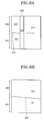
- FIGS. 9 a to 9 gschematically show a process of extending a single crystal Si region by conducting an additional SLS process using a single crystal Si seed region;
- FIG. 10schematically shows a process of carrying out an additional SLS process using the single crystal Si region formed in FIGS. 9 a to 9 g as a seed, thereby extending the single crystal Si region in the reverse y-direction (shown by an arrow);
- FIGS. 11 a to 11 dare sequential views showing a process of forming single crystal Si over the entire substrate by the processes of FIGS. 6 , 9 and 10 ;
- FIGS. 12 a and 12 bshow another embodiment of the present invention, in which several single crystal seed regions are formed at several places of a substrate at the same time so as to reduce process time, and single crystal silicon tiles are formed over the entire substrate using the single crystal seed regions;
- FIGS. 13 a to 13 eshow still another embodiment of the present invention, in which single crystal Si tiles of various patterns are formed over the entire substrate from monocrystalline seed regions in order to reduce process time;
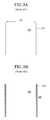
- FIG. 14shows yet another embodiment of the present invention, in which a single crystal is formed on only panel area to eliminate the process time and cost required to convert undesired portions into single crystal regions;
- FIG. 15shows further another embodiment of the present invention, in which a single crystal is formed only on a peripheral circuit-forming area of a panel portion, and portions other than a pixel region and a panel pixel area remain at a-Si without crystallization.
- a poly-Si island patternwhich undergone the prior SLS process, is subjected to an additional laser scanning process in a perpendicular direction to a direction in which grains of the island pattern were grown. This results in formation of a single crystal Si seed region. Then, according to a SLS process using this seed region, a single crystal Si region or a single crystal Si tile is formed over the entire substrate or formed on a certain region of the substrate, such as a region where a panel is formed, or a peripheral circuit region, in order to shorten process time.
- FIG. 6shows the arrangement of a poly-Si island 610 having a width 660 and a length 670 completed in FIG. 5 b and a laser beam 630 having a length 640 and a width 650 for use in the second scanning.
- the laser beam 630is moved in the x-direction perpendicular to the first scanning direction, starting from one edge of the poly-Si island pattern 610 .
- the laser beam length 640 for the second scanningis approximately equal to the length 670 of the poly-Si island pattern 610 .
- a maskis turned by 90° or the sample is turned by 90°.
- FIGS. 7 a , 7 b and 7 cconcretely show the second scanning process.
- the laser beam width 650is generally a few ⁇ m, and the width of an elongated grain in the poly-Si island pattern 610 is in the range of 1 to several ⁇ m.
- FIG. 7 aschematically shows a state where grains are present in one edge of the poly-Si island pattern.
- a grain 710is formed in an elongated shape in the first scanning process, and a grain 711 is not grown in the initial growth process.
- the grain 711has a very small size of about 1 ⁇ m. Since the accuracy of aligning of a laser beam in a SLS system is about sub- ⁇ mw, the laser beam can be aligned such that it melts only a portion of the grain 710 as shown in FIG. 7 b . Of course, parts or all of the grain 730 can be melted. And more important, the size (length and width) of the grain, which was grown in an elongated form over the entire poly-Si island pattern, is similar to the dimension level of the laser beam.
- the region 730is liquefied after the first irradiation in the second scanning process, and the liquefied region is re-solidified.
- the grain 710 and the grain 731which have very small sizes, serve as seeds, and the grain 710 forms most of the seeds.
- the poly-Si region 740 in FIG. 7 bis converted into a single crystal Si region as shown in FIG. 7 c via melting and solidification processes.
- the grain 731When the grain 731 is partially melted upon the first irradiation in the second scanning, it can be grown in the scanning process, but its size is very small and its growth rate is slower than the grain 710 as found in the scanning process, and thus, the size of a newly grown region 751 is negligible.
- the boundary 760 between a portion melted upon the first irradiation of the second scanning and the remaining portionwill disappear. This is because the seed region 710 and the crystallized region 750 have the same orientation.
- seed crystalswill be two crystals having similar growth rates.
- FIGS. 8 a and 8 bshow the second scanning process under this condition.
- two initial seed crystals 820 , 821are scanned with a laser beam 830 while removing a poly-Si region 810 , a grain boundary 800 remaining before scanning extends while the poly-Si island pattern consists of two grains.
- the growth of a grain 870is superior to the growth of a grain 871 so that a region of the grain 870 is larger than the grain 871 .
- such grainssufficiently act as a single crystal seed layer for converting the remaining substrate region or certain region into a single crystal region. This is because the size of the respective grain regions 850 , 851 , 880 , 881 is about several tens ⁇ m sufficiently larger than the width of a laser beam passed through a slit, and thus, a grain suitably chosen from such grains may be applied as a seed crystal for the subsequent crystallization.
- FIGS. 11 a to 11 dshow a method of forming a single crystal Si region over the entire substrate in the above-mentioned manner.
- FIG. 11 ashows that a laser beam 1130 is irradiated starting from one edge of a poly-Si island 1120 formed upon the first scanning, and the second scanning is progressed to one edge of a substrate 1110 in the scanning direction shown in the figure.
- a single crystal Si seed region 1150 of a rectangular shapeis formed and the remaining region remains at a-Si.
- the laser beamis irradiated onto a portion of the single crystal Si seed region 1150 as shown in FIG. 11C , thereby repeating melting and solidification.
- the laser irradiationis conducted in the order of 1170 , 1171 , . . . 1180 , in a direction shown by the reference numeral 1190 . In this way, a single crystal Si region is formed over the entire substrate as shown in FIG. 11 d.
- the respective irradiation steps 1170 , 1171 in FIG. 11 cmay be conducted on several places at the same time such that process time can be shortened.
- the irradiation steps 1170 and 1172are conducted at the same time, and then, the irradiation steps 1171 and 1173 are conducted at the same time.
- This methodhas the following differences from a “2 shot SLS process” (U.S. Pat. No. 6,368,945), which was recently proposed by James Im et al.
- a single crystal Si regionis formed by the first scanning in the x-direction and the second scanning in the y-direction.
- the second scanningsince seed crystals are of small number (about one or two), the second scanning from crystals of small number allows single crystal seed regions to be formed. Once such seed regions are formed, crystallization is conducted in the same manner as the “2 shot SLS process” proposed by James Im et al.
- the “2 shot SLS process”a structure where poly-Si regions are arranged as shown in FIG.
- a single crystal Si regionis formed. Namely, in the present invention, a process of forming the single crystal Si region at an initial stage is added so that the microstructure of a final thin film is greatly changed.
- additional processesfirst and second scanning processes
- the present inventionis advantageous in that the resulting structure provides very high uniformity and degree of freedom of design as compared to the “2 shot SLS process”
- the additional processescan be partially improved as in other embodiments of the present invention which will be described later.
- FIGS. 9 a to 9 g and FIG. 10show the process shown in FIG. 11 c in more detail.
- FIG. 9 ashows a state where a laser beam 910 is shifted by the reference numeral 931 in the reverse y-direction and irradiated onto a single crystal Si region 900 formed upon the second scanning ( FIG. 11 b ).
- the irradiated regionincludes the original single crystal region 921 and the a-Si region 920 , and as shown in FIG. 9 b , a region 940 corresponding to the sum of the two regions is melted.
- FIG. 9 cthere are a region 951 grown from the original single crystal region and a region 950 grown from the a-Si region.
- a single crystal region 961 and a poly-Si region 960are met with each other at a boundary 962 .
- the size of the single crystal regionis increased by a distance 931 moved in the reverse y-direction, thereby extending the single crystal region.
- the laser irradiationis conducted in such a manner that there is no grain formed by nucleation in the melted Si region 952 of FIG. 9 c before the reference numerals 961 and 960 are formed. Since the newly formed single crystal region 961 was grown from the region 900 , an original single crystal region, a boundary 963 is not substantially observed.
- the laser beamis moved in the x-direction and irradiated.
- a region 970which is irradiated with a laser beam 970 , overlaps with a portion of the previously formed region as shown by the reference numeral 972 , thereby removing a boundary effect.
- the irradiated region 971is melted, and as shown in FIG. 9 f , there are a region 981 growing from the single crystal region, and a region 980 growing from the a-Si region.
- a single crystal region 991 and a poly-Si region 990are met with each other. It is believed that the boundary 992 between the previously formed single crystal region 994 and the newly formed single crystal region 991 , and the boundary 993 between the original single crystal region 900 and these single crystal regions, are not substantially observed.
- FIGS. 12 a and 12 bshow a method of forming several single crystal Si seed regions by the first and second scanning processes at the same time.
- An a-Si film 1210is deposited on a substrate 1200 , and irradiated with a laser through a mask where slit patterns were formed. Since several slit patterns are formed in the mask, poly-Si islands 1221 , 1222 , 1223 , 1224 having a width 1230 and a length 1220 are formed upon the first laser scanning at the same time, and irradiated with a laser upon the second scanning in the x-direction at the same time.
- This laser irradiationis conducted in the reverse y-direction, using the single crystal Si regions formed by the second scanning as a seed, to produce single crystal Si tiles 1231 , 1232 , 1233 , 1234 as shown in FIG. 12 b .
- this methodis disadvantageous in that the boundaries between the Si tiles 1231 , 1232 , 1233 , 1234 occur due to a difference in orientation between such Si tiles, it allows process time to be reduced by about 1 ⁇ 4 as compared to the above-mentioned method where the single crystal Si film is formed over the entire substrate.
- This embodimentis advantageously applied for products having a panel region smaller than single crystal Si tile regions.
- FIGS. 13 a to 13 eshow another embodiment of the present invention.
- An a-Si filmis first deposited on a substrate 1300 , and then irradiated with a laser beam through a mask 1304 having slit patterns therein.
- a mask 1304having slit patterns therein.
- slits having a length 1306 and a width 1305are regularly arranged at an interval 1360 from each other.
- a distance moved by the first scanningis shown by the reference numeral 1301 .
- the reference numeral 1312remains at the state of a-Si. Then, after a laser beam is aligned such that it is placed near a boundary 1310 perpendicularly to the first scanning direction upon the second scanning, the second scanning is conducted in the x-direction. In this case, the scanning distance is adjusted such that it is as long as the reference numeral 1302 .
- single crystal Siis progressed toward a-Si regions 1312 , using a certain grain within the respective poly-Si islands as a seed, so that tiles consisting of poly-Si islands and single crystal Si regions 1322 are formed over the entire substrate as shown in FIG. 13 b.
- the regions which were made of the poly-Si islandsare converted into single crystal Si regions 1331 as shown in FIG. 13 c so that single crystal Si regions having a width 1333 and a length 1334 are formed in a tile shape over the entire substrate.
- the reference numeral 1330which was a boundary between the poly-Si island and the single crystal Si region in FIG. 13 b , is not substantially observed.
- various single-crystal Si tile shapes as shown in FIGS. 13 d and 13 ecan be obtained.
- This embodimentis advantageous in that process time is remarkably shortened, since the length of the second scanning over the entire substrate as shown in FIG. 11 b is greatly reduced.
- This embodimentcan be applied for a case where the entire substrate does not need to be made single-crystal according to the panel size, or a case where the reduction of cost is required for products where securing of the uniformity of a Si thin film is important without requiring a Si thin film of quality as high as single crystal Si.
- the size 1302 , 1303 of the tilesneed to be sufficiently small such that it does not affect uniformity.
- the scanning direction and numberare suitably controlled as shown in FIG. 14 , so that only a portion 1440 (pixel region) for forming a panel 1420 , and a peripheral circuit region 1430 , on a substrate 1400 , are made of a single crystal, and the remaining portion is in the form of poly-Si tiles 1410 . This allows process time to be reduced while ensuring uniformity.
- This embodimentcan be applied for products where a peripheral circuit has high switching speed, and the size of a panel is large.
- an a-Si film 1520is deposited on a substrate 1500 , only a peripheral circuit region 1530 of a panel 1510 is made of a single crystal, and a pixel region 1540 remains at a-Si.
- This embodimentcan be applied in a case where a-Si TFT having low leakage current is disposed at a pixel region, and peripheral TFT requiring high-speed switching is made of a single crystal. This embodiment allows process time to be remarkably reduced while ensuring a characteristic of low leakage current.
- the single crystal Si seed regionis formed by the additional laser irradiation process using one or two seed grains, which were formed in an elongated shape within a poly-Si, island formed by the prior SLS process. Starting from this seed region, the single crystal Si region can be formed over the entire substrate or a portion or certain region of the substrate.
- the present inventionallows the uniformity problem to be fundamentally solved, so that it is possible to cope with various product designs. Furthermore, in fabricating a panel on the single crystal Si region, it can cope with switching speed in a peripheral circuit.
- the insulating filmis a silicon nitride or oxide film selected from SiO x , SiO x H y , SiN x and can be either bi-layer or multiple-layer or a film of nitride or oxide of a metal selected from Al, Cu, Ti and W.
- the semiconductor layercan be made of a material selected from either a-Si (amorphous silicon), a-Ge (amorphous germanium), a-Si x ,Ge y (amorphous silicon germanium), poly-Si (poly-crystalline silicon), poly-Ge (poly-crystalline germanium) or poly-SixGey (poly-crystalline silicon-germanium).
- the metal filmcan be made of a metal selected from Al, Cu, Ti, W, Au or silver or compound of any of these metals and a semiconductor.
- peripheral circuit partsare integrated to reduce the cost of module parts.
- single crystal siliconis applied unlike the existing process, sufficient switching speed allowing a drive circuit and also various interface parts to be integrated can be exhibited so that a system-on-panel can be ultimately formed.
- the present inventionis applied for a wider range of products than existing LTPS TFT-LCD products.
- a pixel regionmay also be formed of a-Si, products can be produced, which have a characteristic of low leakage current and where a peripheral circuit is integrated. Also, process costs can be greatly reduced.
- a pixel regionwhen a pixel region is made of single crystal silicon, it can exhibit high current so that it is suitable in OLED, a current drive type display, and low voltage driving becomes possible.
- the present inventioncan realize formation of single crystal Si on a large-sized glass substrate and also a small-sized substrate such as a Si wafer, it may also be applied in SOI (system-on-insulator) in a semiconductor memory integrated circuit process or in a three-dimensional integrated circuit process.
- SOIsystem-on-insulator
Landscapes
- Engineering & Computer Science (AREA)
- Physics & Mathematics (AREA)
- Chemical & Material Sciences (AREA)
- Microelectronics & Electronic Packaging (AREA)
- Power Engineering (AREA)
- Computer Hardware Design (AREA)
- Manufacturing & Machinery (AREA)
- General Physics & Mathematics (AREA)
- Condensed Matter Physics & Semiconductors (AREA)
- Crystallography & Structural Chemistry (AREA)
- Materials Engineering (AREA)
- Optics & Photonics (AREA)
- Organic Chemistry (AREA)
- Metallurgy (AREA)
- Electromagnetism (AREA)
- Health & Medical Sciences (AREA)
- Toxicology (AREA)
- Recrystallisation Techniques (AREA)
- Thin Film Transistor (AREA)
Abstract
Description


Claims (10)
Applications Claiming Priority (2)
| Application Number | Priority Date | Filing Date | Title |
|---|---|---|---|
| KR2003-19953 | 2003-03-31 | ||
| KR1020030019953AKR100618184B1 (en) | 2003-03-31 | 2003-03-31 | Crystallization method |
Publications (2)
| Publication Number | Publication Date |
|---|---|
| US20040192013A1 US20040192013A1 (en) | 2004-09-30 |
| US7135388B2true US7135388B2 (en) | 2006-11-14 |
Family
ID=32985911
Family Applications (1)
| Application Number | Title | Priority Date | Filing Date |
|---|---|---|---|
| US10/714,226Expired - LifetimeUS7135388B2 (en) | 2003-03-31 | 2003-11-14 | Method for fabricating single crystal silicon film |
Country Status (5)
| Country | Link |
|---|---|
| US (1) | US7135388B2 (en) |
| JP (1) | JP2004311935A (en) |
| KR (1) | KR100618184B1 (en) |
| CN (1) | CN100377294C (en) |
| TW (1) | TWI310059B (en) |
Cited By (26)
| Publication number | Priority date | Publication date | Assignee | Title |
|---|---|---|---|---|
| US20020083557A1 (en)* | 2000-12-28 | 2002-07-04 | Yun-Ho Jung | Apparatus and method of crystallizing amorphous silicon |
| US20080214021A1 (en)* | 2007-01-24 | 2008-09-04 | Semiconductor Energy Laboratory Co., Ltd. | Method of crystallizing semiconductor film and method of manufacturing semiconductor device |
| US20080217292A1 (en)* | 2007-03-06 | 2008-09-11 | Micron Technology, Inc. | Registered structure formation via the application of directed thermal energy to diblock copolymer films |
| US20080237724A1 (en)* | 2007-03-29 | 2008-10-02 | Nec Lcd Technologies, Ltd. | Semiconductor thin film manufacturing method, semiconductor thin film and thin film transistor |
| US20090117707A1 (en)* | 2007-11-01 | 2009-05-07 | Semiconductor Energy Laboratory Co., Ltd. | Method for manufacturing soi substrate and semiconductor device |
| US20090200646A1 (en)* | 2008-02-13 | 2009-08-13 | Millward Dan B | One-Dimensional Arrays of Block Copolymer Cylinders and Applications Thereof |
| US20090263628A1 (en)* | 2008-04-21 | 2009-10-22 | Millward Dan B | Multi-Layer Method for Formation of Registered Arrays of Cylindrical Pores in Polymer Films |
| US20090274887A1 (en)* | 2008-05-02 | 2009-11-05 | Millward Dan B | Graphoepitaxial Self-Assembly of Arrays of Downward Facing Half-Cylinders |
| US20100112792A1 (en)* | 2008-11-03 | 2010-05-06 | International Business Machines Corporation | Thick epitaxial silicon by grain reorientation annealing and applications thereof |
| US20100301415A1 (en)* | 2007-06-25 | 2010-12-02 | Semiconductor Energy Laboratory Co., Ltd. | Method for manufacturing semiconductor substrate, and semiconductor device |
| US8080615B2 (en) | 2007-06-19 | 2011-12-20 | Micron Technology, Inc. | Crosslinkable graft polymer non-preferentially wetted by polystyrene and polyethylene oxide |
| US8372295B2 (en) | 2007-04-20 | 2013-02-12 | Micron Technology, Inc. | Extensions of self-assembled structures to increased dimensions via a “bootstrap” self-templating method |
| US8394483B2 (en) | 2007-01-24 | 2013-03-12 | Micron Technology, Inc. | Two-dimensional arrays of holes with sub-lithographic diameters formed by block copolymer self-assembly |
| US8404124B2 (en) | 2007-06-12 | 2013-03-26 | Micron Technology, Inc. | Alternating self-assembling morphologies of diblock copolymers controlled by variations in surfaces |
| US8425982B2 (en) | 2008-03-21 | 2013-04-23 | Micron Technology, Inc. | Methods of improving long range order in self-assembly of block copolymer films with ionic liquids |
| US8426313B2 (en) | 2008-03-21 | 2013-04-23 | Micron Technology, Inc. | Thermal anneal of block copolymer films with top interface constrained to wet both blocks with equal preference |
| US8450418B2 (en) | 2010-08-20 | 2013-05-28 | Micron Technology, Inc. | Methods of forming block copolymers, and block copolymer compositions |
| US8551808B2 (en) | 2007-06-21 | 2013-10-08 | Micron Technology, Inc. | Methods of patterning a substrate including multilayer antireflection coatings |
| US8557128B2 (en) | 2007-03-22 | 2013-10-15 | Micron Technology, Inc. | Sub-10 nm line features via rapid graphoepitaxial self-assembly of amphiphilic monolayers |
| US8669645B2 (en) | 2008-10-28 | 2014-03-11 | Micron Technology, Inc. | Semiconductor structures including polymer material permeated with metal oxide |
| US8900963B2 (en) | 2011-11-02 | 2014-12-02 | Micron Technology, Inc. | Methods of forming semiconductor device structures, and related structures |
| US8956713B2 (en) | 2007-04-18 | 2015-02-17 | Micron Technology, Inc. | Methods of forming a stamp and a stamp |
| US8999492B2 (en) | 2008-02-05 | 2015-04-07 | Micron Technology, Inc. | Method to produce nanometer-sized features with directed assembly of block copolymers |
| US9087699B2 (en) | 2012-10-05 | 2015-07-21 | Micron Technology, Inc. | Methods of forming an array of openings in a substrate, and related methods of forming a semiconductor device structure |
| US9177795B2 (en) | 2013-09-27 | 2015-11-03 | Micron Technology, Inc. | Methods of forming nanostructures including metal oxides |
| US9229328B2 (en) | 2013-05-02 | 2016-01-05 | Micron Technology, Inc. | Methods of forming semiconductor device structures, and related semiconductor device structures |
Families Citing this family (29)
| Publication number | Priority date | Publication date | Assignee | Title |
|---|---|---|---|---|
| KR100496251B1 (en)* | 2002-11-25 | 2005-06-17 | 엘지.필립스 엘시디 주식회사 | Method of Solidification for Amorphous Silicon layer using a Sequential Lateral Solidification Crystallization Technology |
| US7164152B2 (en) | 2003-09-16 | 2007-01-16 | The Trustees Of Columbia University In The City Of New York | Laser-irradiated thin films having variable thickness |
| US7318866B2 (en) | 2003-09-16 | 2008-01-15 | The Trustees Of Columbia University In The City Of New York | Systems and methods for inducing crystallization of thin films using multiple optical paths |
| WO2005034193A2 (en) | 2003-09-19 | 2005-04-14 | The Trustees Of Columbia University In The City Ofnew York | Single scan irradiation for crystallization of thin films |
| US7645337B2 (en) | 2004-11-18 | 2010-01-12 | The Trustees Of Columbia University In The City Of New York | Systems and methods for creating crystallographic-orientation controlled poly-silicon films |
| JP5068171B2 (en)* | 2004-11-18 | 2012-11-07 | ザ トラスティーズ オブ コロンビア ユニヴァーシティ イン ザ シティ オブ ニューヨーク | System and method for producing a crystallographically controlled polysilicon film |
| KR100599043B1 (en)* | 2005-03-18 | 2006-07-12 | 삼성전자주식회사 | Manufacturing Method of Semiconductor Device |
| US8221544B2 (en) | 2005-04-06 | 2012-07-17 | The Trustees Of Columbia University In The City Of New York | Line scan sequential lateral solidification of thin films |
| KR101167662B1 (en) | 2005-08-04 | 2012-07-23 | 삼성전자주식회사 | Mask for sequential lateral solidification and method of manufacturing the same |
| KR101132404B1 (en)* | 2005-08-19 | 2012-04-03 | 삼성전자주식회사 | Method for fabricating thin film of poly crystalline silicon and method for fabricating thin film transistor having the same |
| KR100731752B1 (en) | 2005-09-07 | 2007-06-22 | 삼성에스디아이 주식회사 | Thin film transistor |
| US8598588B2 (en) | 2005-12-05 | 2013-12-03 | The Trustees Of Columbia University In The City Of New York | Systems and methods for processing a film, and thin films |
| KR100928664B1 (en)* | 2007-04-09 | 2009-11-27 | 삼성전자주식회사 | Manufacturing Method of NAND Flash Memory Device |
| US20070262311A1 (en)* | 2006-05-11 | 2007-11-15 | Toppoly Optoelectronics Corp. | Flat panel display and fabrication method and thereof |
| KR100803867B1 (en)* | 2006-09-14 | 2008-02-14 | 연세대학교 산학협력단 | Crystallization method of amorphous silicon layer and manufacturing method of thin film transistor using same |
| TW200942935A (en) | 2007-09-21 | 2009-10-16 | Univ Columbia | Collections of laterally crystallized semiconductor islands for use in thin film transistors and systems and methods for making same |
| JP5385289B2 (en) | 2007-09-25 | 2014-01-08 | ザ トラスティーズ オブ コロンビア ユニヴァーシティ イン ザ シティ オブ ニューヨーク | Method for producing high uniformity in thin film transistor devices fabricated on laterally crystallized thin films |
| WO2009067687A1 (en) | 2007-11-21 | 2009-05-28 | The Trustees Of Columbia University In The City Of New York | Systems and methods for preparation of epitaxially textured thick films |
| WO2009067688A1 (en) | 2007-11-21 | 2009-05-28 | The Trustees Of Columbia University In The City Of New York | Systems and methods for preparing epitaxially textured polycrystalline films |
| US8012861B2 (en) | 2007-11-21 | 2011-09-06 | The Trustees Of Columbia University In The City Of New York | Systems and methods for preparing epitaxially textured polycrystalline films |
| US8569155B2 (en) | 2008-02-29 | 2013-10-29 | The Trustees Of Columbia University In The City Of New York | Flash lamp annealing crystallization for large area thin films |
| JP2009302251A (en)* | 2008-06-12 | 2009-12-24 | Sharp Corp | Laser crystallization device, mask, laser crystallization method, crystal material, and semiconductor element |
| JP2012508985A (en) | 2008-11-14 | 2012-04-12 | ザ トラスティーズ オブ コロンビア ユニヴァーシティ イン ザ シティ オブ ニューヨーク | System and method for thin film crystallization |
| US9087696B2 (en) | 2009-11-03 | 2015-07-21 | The Trustees Of Columbia University In The City Of New York | Systems and methods for non-periodic pulse partial melt film processing |
| US8440581B2 (en) | 2009-11-24 | 2013-05-14 | The Trustees Of Columbia University In The City Of New York | Systems and methods for non-periodic pulse sequential lateral solidification |
| US9646831B2 (en) | 2009-11-03 | 2017-05-09 | The Trustees Of Columbia University In The City Of New York | Advanced excimer laser annealing for thin films |
| KR101642834B1 (en) | 2010-04-09 | 2016-08-11 | 삼성전자주식회사 | Method of manufacturing semiconductor device having a soi layer in a required region of bulk silicon wafer using a leg process |
| US9356171B2 (en)* | 2012-01-25 | 2016-05-31 | The Trustees Of Dartmouth College | Method of forming single-crystal semiconductor layers and photovaltaic cell thereon |
| CN106702495A (en)* | 2016-12-27 | 2017-05-24 | 陕西科技大学 | Method for preparing single crystal film |
Citations (3)
| Publication number | Priority date | Publication date | Assignee | Title |
|---|---|---|---|---|
| US5304357A (en)* | 1991-05-15 | 1994-04-19 | Ricoh Co. Ltd. | Apparatus for zone melting recrystallization of thin semiconductor film |
| US6113689A (en)* | 1997-05-12 | 2000-09-05 | Lg Electronics Inc. | Method of crystallizing amorphous silicon layer |
| US6326286B1 (en)* | 1998-06-09 | 2001-12-04 | Lg. Philips Lcd Co., Ltd. | Method for crystallizing amorphous silicon layer |
Family Cites Families (3)
| Publication number | Priority date | Publication date | Assignee | Title |
|---|---|---|---|---|
| US6326248B1 (en)* | 1994-06-02 | 2001-12-04 | Semiconductor Energy Laboratory Co., Ltd. | Process for fabricating semiconductor device |
| TW303526B (en)* | 1994-12-27 | 1997-04-21 | Matsushita Electric Industrial Co Ltd | |
| JP3715848B2 (en)* | 1999-09-22 | 2005-11-16 | シャープ株式会社 | Manufacturing method of semiconductor device |
- 2003
- 2003-03-31KRKR1020030019953Apatent/KR100618184B1/ennot_activeExpired - Lifetime
- 2003-11-14TWTW092131894Apatent/TWI310059B/ennot_activeIP Right Cessation
- 2003-11-14USUS10/714,226patent/US7135388B2/ennot_activeExpired - Lifetime
- 2003-11-20JPJP2003391471Apatent/JP2004311935A/enactivePending
- 2004
- 2004-01-07CNCNB2004100013826Apatent/CN100377294C/ennot_activeExpired - Lifetime
Patent Citations (3)
| Publication number | Priority date | Publication date | Assignee | Title |
|---|---|---|---|---|
| US5304357A (en)* | 1991-05-15 | 1994-04-19 | Ricoh Co. Ltd. | Apparatus for zone melting recrystallization of thin semiconductor film |
| US6113689A (en)* | 1997-05-12 | 2000-09-05 | Lg Electronics Inc. | Method of crystallizing amorphous silicon layer |
| US6326286B1 (en)* | 1998-06-09 | 2001-12-04 | Lg. Philips Lcd Co., Ltd. | Method for crystallizing amorphous silicon layer |
Cited By (65)
| Publication number | Priority date | Publication date | Assignee | Title |
|---|---|---|---|---|
| US20020083557A1 (en)* | 2000-12-28 | 2002-07-04 | Yun-Ho Jung | Apparatus and method of crystallizing amorphous silicon |
| US7357963B2 (en)* | 2000-12-28 | 2008-04-15 | Lg.Philips Lcd Co., Ltd. | Apparatus and method of crystallizing amorphous silicon |
| US20080149029A1 (en)* | 2000-12-28 | 2008-06-26 | Yun-Ho Jung | Apparatus and method of crystallizing amorphous silicon |
| US8394483B2 (en) | 2007-01-24 | 2013-03-12 | Micron Technology, Inc. | Two-dimensional arrays of holes with sub-lithographic diameters formed by block copolymer self-assembly |
| US8349714B2 (en)* | 2007-01-24 | 2013-01-08 | Semiconductor Energy Laboratory Co., Ltd. | Method of crystallizing semiconductor film and method of manufacturing semiconductor device |
| US20080214021A1 (en)* | 2007-01-24 | 2008-09-04 | Semiconductor Energy Laboratory Co., Ltd. | Method of crystallizing semiconductor film and method of manufacturing semiconductor device |
| US8512846B2 (en) | 2007-01-24 | 2013-08-20 | Micron Technology, Inc. | Two-dimensional arrays of holes with sub-lithographic diameters formed by block copolymer self-assembly |
| US20080217292A1 (en)* | 2007-03-06 | 2008-09-11 | Micron Technology, Inc. | Registered structure formation via the application of directed thermal energy to diblock copolymer films |
| US8083953B2 (en) | 2007-03-06 | 2011-12-27 | Micron Technology, Inc. | Registered structure formation via the application of directed thermal energy to diblock copolymer films |
| US8409449B2 (en) | 2007-03-06 | 2013-04-02 | Micron Technology, Inc. | Registered structure formation via the application of directed thermal energy to diblock copolymer films |
| US8753738B2 (en) | 2007-03-06 | 2014-06-17 | Micron Technology, Inc. | Registered structure formation via the application of directed thermal energy to diblock copolymer films |
| US8801894B2 (en) | 2007-03-22 | 2014-08-12 | Micron Technology, Inc. | Sub-10 NM line features via rapid graphoepitaxial self-assembly of amphiphilic monolayers |
| US8784974B2 (en) | 2007-03-22 | 2014-07-22 | Micron Technology, Inc. | Sub-10 NM line features via rapid graphoepitaxial self-assembly of amphiphilic monolayers |
| US8557128B2 (en) | 2007-03-22 | 2013-10-15 | Micron Technology, Inc. | Sub-10 nm line features via rapid graphoepitaxial self-assembly of amphiphilic monolayers |
| US20080237724A1 (en)* | 2007-03-29 | 2008-10-02 | Nec Lcd Technologies, Ltd. | Semiconductor thin film manufacturing method, semiconductor thin film and thin film transistor |
| US9768021B2 (en) | 2007-04-18 | 2017-09-19 | Micron Technology, Inc. | Methods of forming semiconductor device structures including metal oxide structures |
| US9276059B2 (en) | 2007-04-18 | 2016-03-01 | Micron Technology, Inc. | Semiconductor device structures including metal oxide structures |
| US8956713B2 (en) | 2007-04-18 | 2015-02-17 | Micron Technology, Inc. | Methods of forming a stamp and a stamp |
| US9142420B2 (en) | 2007-04-20 | 2015-09-22 | Micron Technology, Inc. | Extensions of self-assembled structures to increased dimensions via a “bootstrap” self-templating method |
| US8372295B2 (en) | 2007-04-20 | 2013-02-12 | Micron Technology, Inc. | Extensions of self-assembled structures to increased dimensions via a “bootstrap” self-templating method |
| US8404124B2 (en) | 2007-06-12 | 2013-03-26 | Micron Technology, Inc. | Alternating self-assembling morphologies of diblock copolymers controlled by variations in surfaces |
| US8609221B2 (en) | 2007-06-12 | 2013-12-17 | Micron Technology, Inc. | Alternating self-assembling morphologies of diblock copolymers controlled by variations in surfaces |
| US9257256B2 (en) | 2007-06-12 | 2016-02-09 | Micron Technology, Inc. | Templates including self-assembled block copolymer films |
| US8513359B2 (en) | 2007-06-19 | 2013-08-20 | Micron Technology, Inc. | Crosslinkable graft polymer non preferentially wetted by polystyrene and polyethylene oxide |
| US8785559B2 (en) | 2007-06-19 | 2014-07-22 | Micron Technology, Inc. | Crosslinkable graft polymer non-preferentially wetted by polystyrene and polyethylene oxide |
| US8445592B2 (en) | 2007-06-19 | 2013-05-21 | Micron Technology, Inc. | Crosslinkable graft polymer non-preferentially wetted by polystyrene and polyethylene oxide |
| US8080615B2 (en) | 2007-06-19 | 2011-12-20 | Micron Technology, Inc. | Crosslinkable graft polymer non-preferentially wetted by polystyrene and polyethylene oxide |
| US8551808B2 (en) | 2007-06-21 | 2013-10-08 | Micron Technology, Inc. | Methods of patterning a substrate including multilayer antireflection coatings |
| US8330221B2 (en)* | 2007-06-25 | 2012-12-11 | Semiconductor Energy Laboratory Co., Ltd. | Method for manufacturing semiconductor substrate, and semiconductor device |
| US20100301415A1 (en)* | 2007-06-25 | 2010-12-02 | Semiconductor Energy Laboratory Co., Ltd. | Method for manufacturing semiconductor substrate, and semiconductor device |
| US20090117707A1 (en)* | 2007-11-01 | 2009-05-07 | Semiconductor Energy Laboratory Co., Ltd. | Method for manufacturing soi substrate and semiconductor device |
| US11560009B2 (en) | 2008-02-05 | 2023-01-24 | Micron Technology, Inc. | Stamps including a self-assembled block copolymer material, and related methods |
| US10005308B2 (en) | 2008-02-05 | 2018-06-26 | Micron Technology, Inc. | Stamps and methods of forming a pattern on a substrate |
| US10828924B2 (en) | 2008-02-05 | 2020-11-10 | Micron Technology, Inc. | Methods of forming a self-assembled block copolymer material |
| US8999492B2 (en) | 2008-02-05 | 2015-04-07 | Micron Technology, Inc. | Method to produce nanometer-sized features with directed assembly of block copolymers |
| US8101261B2 (en) | 2008-02-13 | 2012-01-24 | Micron Technology, Inc. | One-dimensional arrays of block copolymer cylinders and applications thereof |
| US8642157B2 (en) | 2008-02-13 | 2014-02-04 | Micron Technology, Inc. | One-dimensional arrays of block copolymer cylinders and applications thereof |
| US20090200646A1 (en)* | 2008-02-13 | 2009-08-13 | Millward Dan B | One-Dimensional Arrays of Block Copolymer Cylinders and Applications Thereof |
| US8641914B2 (en) | 2008-03-21 | 2014-02-04 | Micron Technology, Inc. | Methods of improving long range order in self-assembly of block copolymer films with ionic liquids |
| US8633112B2 (en) | 2008-03-21 | 2014-01-21 | Micron Technology, Inc. | Thermal anneal of block copolymer films with top interface constrained to wet both blocks with equal preference |
| US10153200B2 (en) | 2008-03-21 | 2018-12-11 | Micron Technology, Inc. | Methods of forming a nanostructured polymer material including block copolymer materials |
| US9315609B2 (en) | 2008-03-21 | 2016-04-19 | Micron Technology, Inc. | Thermal anneal of block copolymer films with top interface constrained to wet both blocks with equal preference |
| US11282741B2 (en) | 2008-03-21 | 2022-03-22 | Micron Technology, Inc. | Methods of forming a semiconductor device using block copolymer materials |
| US9682857B2 (en) | 2008-03-21 | 2017-06-20 | Micron Technology, Inc. | Methods of improving long range order in self-assembly of block copolymer films with ionic liquids and materials produced therefrom |
| US8426313B2 (en) | 2008-03-21 | 2013-04-23 | Micron Technology, Inc. | Thermal anneal of block copolymer films with top interface constrained to wet both blocks with equal preference |
| US8425982B2 (en) | 2008-03-21 | 2013-04-23 | Micron Technology, Inc. | Methods of improving long range order in self-assembly of block copolymer films with ionic liquids |
| US8114300B2 (en) | 2008-04-21 | 2012-02-14 | Micron Technology, Inc. | Multi-layer method for formation of registered arrays of cylindrical pores in polymer films |
| US8455082B2 (en) | 2008-04-21 | 2013-06-04 | Micron Technology, Inc. | Polymer materials for formation of registered arrays of cylindrical pores |
| US20090263628A1 (en)* | 2008-04-21 | 2009-10-22 | Millward Dan B | Multi-Layer Method for Formation of Registered Arrays of Cylindrical Pores in Polymer Films |
| US8993088B2 (en) | 2008-05-02 | 2015-03-31 | Micron Technology, Inc. | Polymeric materials in self-assembled arrays and semiconductor structures comprising polymeric materials |
| US20090274887A1 (en)* | 2008-05-02 | 2009-11-05 | Millward Dan B | Graphoepitaxial Self-Assembly of Arrays of Downward Facing Half-Cylinders |
| US8114301B2 (en) | 2008-05-02 | 2012-02-14 | Micron Technology, Inc. | Graphoepitaxial self-assembly of arrays of downward facing half-cylinders |
| US8518275B2 (en) | 2008-05-02 | 2013-08-27 | Micron Technology, Inc. | Graphoepitaxial self-assembly of arrays of downward facing half-cylinders |
| US8669645B2 (en) | 2008-10-28 | 2014-03-11 | Micron Technology, Inc. | Semiconductor structures including polymer material permeated with metal oxide |
| US7914619B2 (en)* | 2008-11-03 | 2011-03-29 | International Business Machines Corporation | Thick epitaxial silicon by grain reorientation annealing and applications thereof |
| US20100112792A1 (en)* | 2008-11-03 | 2010-05-06 | International Business Machines Corporation | Thick epitaxial silicon by grain reorientation annealing and applications thereof |
| US8450418B2 (en) | 2010-08-20 | 2013-05-28 | Micron Technology, Inc. | Methods of forming block copolymers, and block copolymer compositions |
| US9431605B2 (en) | 2011-11-02 | 2016-08-30 | Micron Technology, Inc. | Methods of forming semiconductor device structures |
| US8900963B2 (en) | 2011-11-02 | 2014-12-02 | Micron Technology, Inc. | Methods of forming semiconductor device structures, and related structures |
| US9087699B2 (en) | 2012-10-05 | 2015-07-21 | Micron Technology, Inc. | Methods of forming an array of openings in a substrate, and related methods of forming a semiconductor device structure |
| US9229328B2 (en) | 2013-05-02 | 2016-01-05 | Micron Technology, Inc. | Methods of forming semiconductor device structures, and related semiconductor device structures |
| US10049874B2 (en) | 2013-09-27 | 2018-08-14 | Micron Technology, Inc. | Self-assembled nanostructures including metal oxides and semiconductor structures comprised thereof |
| US11532477B2 (en) | 2013-09-27 | 2022-12-20 | Micron Technology, Inc. | Self-assembled nanostructures including metal oxides and semiconductor structures comprised thereof |
| US9177795B2 (en) | 2013-09-27 | 2015-11-03 | Micron Technology, Inc. | Methods of forming nanostructures including metal oxides |
| US12400856B2 (en) | 2013-09-27 | 2025-08-26 | Micron Technology, Inc. | Methods of forming nanostructures including metal oxides using block copolymer materials |
Also Published As
| Publication number | Publication date |
|---|---|
| KR20040085310A (en) | 2004-10-08 |
| KR100618184B1 (en) | 2006-08-31 |
| JP2004311935A (en) | 2004-11-04 |
| TWI310059B (en) | 2009-05-21 |
| TW200419017A (en) | 2004-10-01 |
| CN1534725A (en) | 2004-10-06 |
| CN100377294C (en) | 2008-03-26 |
| US20040192013A1 (en) | 2004-09-30 |
Similar Documents
| Publication | Publication Date | Title |
|---|---|---|
| US7135388B2 (en) | Method for fabricating single crystal silicon film | |
| US6495405B2 (en) | Method of optimizing channel characteristics using laterally-crystallized ELA poly-Si films | |
| US7354810B2 (en) | Method of and apparatus for manufacturing semiconductor thin film, and method of manufacturing thin film transistor | |
| US7645337B2 (en) | Systems and methods for creating crystallographic-orientation controlled poly-silicon films | |
| CN100555570C (en) | Form the method for polysilicon membrane and with the method for this method manufacturing thin-film transistor | |
| US6573163B2 (en) | Method of optimizing channel characteristics using multiple masks to form laterally crystallized ELA poly-Si films | |
| JP5068171B2 (en) | System and method for producing a crystallographically controlled polysilicon film | |
| JP4637410B2 (en) | Semiconductor substrate manufacturing method and semiconductor device | |
| JP2003332346A (en) | Thin film transistor and method of manufacturing the same | |
| KR100577795B1 (en) | Polycrystalline Silicon Film Formation Method | |
| US20020102821A1 (en) | Mask pattern design to improve quality uniformity in lateral laser crystallized poly-Si films | |
| US7008863B2 (en) | Method for forming polycrystalline silicon film | |
| US7033915B2 (en) | Method for crystallizing amorphous silicon film | |
| JP2004063478A (en) | Thin film transistor and method of manufacturing the same | |
| US20070238270A1 (en) | Method for forming polycrystalline film | |
| KR100860007B1 (en) | Thin film transistor, manufacturing method of thin film transistor, organic light emitting display device having same and manufacturing method thereof | |
| JP3338756B2 (en) | Semiconductor device and method of manufacturing the same | |
| KR101095368B1 (en) | Polycrystalline thin film formation method | |
| KR100709163B1 (en) | Polycrystalline Silicon Thin Film Formation Method | |
| KR20050022086A (en) | Method for fabricating polysilicon thin film transistor | |
| JP2004311910A (en) | Thin film transistor and its manufacturing method |
Legal Events
| Date | Code | Title | Description |
|---|---|---|---|
| AS | Assignment | Owner name:BOE HYDIS TECHNOLOGY CO., LTD., KOREA, REPUBLIC OF Free format text:ASSIGNMENT OF ASSIGNORS INTEREST;ASSIGNORS:RYU, MYUNG KWAN;LEE, HO NYEON;PARK, JAE CHUL;AND OTHERS;REEL/FRAME:014705/0892 Effective date:20031105 | |
| STCF | Information on status: patent grant | Free format text:PATENTED CASE | |
| FEPP | Fee payment procedure | Free format text:PAYOR NUMBER ASSIGNED (ORIGINAL EVENT CODE: ASPN); ENTITY STATUS OF PATENT OWNER: LARGE ENTITY | |
| FEPP | Fee payment procedure | Free format text:PAYOR NUMBER ASSIGNED (ORIGINAL EVENT CODE: ASPN); ENTITY STATUS OF PATENT OWNER: LARGE ENTITY Free format text:PAYER NUMBER DE-ASSIGNED (ORIGINAL EVENT CODE: RMPN); ENTITY STATUS OF PATENT OWNER: LARGE ENTITY | |
| FPAY | Fee payment | Year of fee payment:4 | |
| FPAY | Fee payment | Year of fee payment:8 | |
| FEPP | Fee payment procedure | Free format text:PAT HOLDER CLAIMS SMALL ENTITY STATUS, ENTITY STATUS SET TO SMALL (ORIGINAL EVENT CODE: LTOS); ENTITY STATUS OF PATENT OWNER: LARGE ENTITY | |
| MAFP | Maintenance fee payment | Free format text:PAYMENT OF MAINTENANCE FEE, 12TH YR, SMALL ENTITY (ORIGINAL EVENT CODE: M2553) Year of fee payment:12 | |
| FEPP | Fee payment procedure | Free format text:ENTITY STATUS SET TO UNDISCOUNTED (ORIGINAL EVENT CODE: BIG.); ENTITY STATUS OF PATENT OWNER: LARGE ENTITY | |
| MAFP | Maintenance fee payment | Free format text:PAYMENT OF MAINTENANCE FEE UNDER 1.28(C) (ORIGINAL EVENT CODE: M1559); ENTITY STATUS OF PATENT OWNER: LARGE ENTITY | |
| FEPP | Fee payment procedure | Free format text:PETITION RELATED TO MAINTENANCE FEES GRANTED (ORIGINAL EVENT CODE: PTGR); ENTITY STATUS OF PATENT OWNER: LARGE ENTITY |