US7133070B2 - System and method for deciding when to correct image-specific defects based on camera, scene, display and demographic data - Google Patents
System and method for deciding when to correct image-specific defects based on camera, scene, display and demographic dataDownload PDFInfo
- Publication number
- US7133070B2 US7133070B2US09/957,013US95701301AUS7133070B2US 7133070 B2US7133070 B2US 7133070B2US 95701301 AUS95701301 AUS 95701301AUS 7133070 B2US7133070 B2US 7133070B2
- Authority
- US
- United States
- Prior art keywords
- image
- meta data
- defect
- captured image
- exposure
- Prior art date
- Legal status (The legal status is an assumption and is not a legal conclusion. Google has not performed a legal analysis and makes no representation as to the accuracy of the status listed.)
- Expired - Lifetime, expires
Links
Images


Classifications
- H—ELECTRICITY
- H04—ELECTRIC COMMUNICATION TECHNIQUE
- H04N—PICTORIAL COMMUNICATION, e.g. TELEVISION
- H04N1/00—Scanning, transmission or reproduction of documents or the like, e.g. facsimile transmission; Details thereof
- H04N1/46—Colour picture communication systems
- H04N1/56—Processing of colour picture signals
- H04N1/60—Colour correction or control
- H04N1/62—Retouching, i.e. modification of isolated colours only or in isolated picture areas only
- H—ELECTRICITY
- H04—ELECTRIC COMMUNICATION TECHNIQUE
- H04N—PICTORIAL COMMUNICATION, e.g. TELEVISION
- H04N1/00—Scanning, transmission or reproduction of documents or the like, e.g. facsimile transmission; Details thereof
- H04N1/40—Picture signal circuits
- H—ELECTRICITY
- H04—ELECTRIC COMMUNICATION TECHNIQUE
- H04N—PICTORIAL COMMUNICATION, e.g. TELEVISION
- H04N1/00—Scanning, transmission or reproduction of documents or the like, e.g. facsimile transmission; Details thereof
- H04N1/46—Colour picture communication systems
- H04N1/56—Processing of colour picture signals
- H04N1/60—Colour correction or control
- H04N1/6083—Colour correction or control controlled by factors external to the apparatus
- H04N1/6086—Colour correction or control controlled by factors external to the apparatus by scene illuminant, i.e. conditions at the time of picture capture, e.g. flash, optical filter used, evening, cloud, daylight, artificial lighting, white point measurement, colour temperature
- H—ELECTRICITY
- H04—ELECTRIC COMMUNICATION TECHNIQUE
- H04N—PICTORIAL COMMUNICATION, e.g. TELEVISION
- H04N1/00—Scanning, transmission or reproduction of documents or the like, e.g. facsimile transmission; Details thereof
- H04N1/46—Colour picture communication systems
- H04N1/56—Processing of colour picture signals
- H04N1/60—Colour correction or control
- H04N1/62—Retouching, i.e. modification of isolated colours only or in isolated picture areas only
- H04N1/624—Red-eye correction
Definitions
- This inventionrelates generally to the field of digital image processing, and, in particular, to the prediction and correction of image defects in a photograph.
- Photographic systemsproduce a wide range of image quality when operated by amateur, often referred to as “point-and-shoot”, photographers. If the photographic environment for a given scene is well suited to the image capture system (e.g. subjects are stationary and within the focus range, ambient light level is uniform and of sufficient intensity, and lens magnification is appropriate for the subject matter), good results are typically obtained. However, when these conditions are not present, image defects may be introduced due to failures in the capture or reproduction system, thereby reducing the quality of the final viewed image. To minimize the effects of suboptimal image capture conditions, camera designers have attempted to compensate by adding features intended to expand the range of light levels and distances where images can be captured. Unfortunately, these features often solve the primary problem, but add a secondary, sometimes severe, image defect.
- the intensity of the ambient lightis insufficient to provide adequate exposure, and the primary subject is located less than 20 feet from the camera, most built-in electronic flash units are able to provide auxiliary illumination sufficient to at least partially expose the primary subject.
- the flashmay introduce image defects.
- the image defect known as redeyemay occur when the angle between a narrow light source, the photographic subject, and the camera lens is less than approximately three degrees. This criterion is frequently met in flash exposures from compact cameras. The light from the flash enters the pupil nearly on-axis and propagates to the fundus of the eye, where it is reflected back out of the eye, having been colored red by the blood vessels in the fundus. The light exits the eye in a narrow cone, and if the camera lens falls within that cone, the red reflection will be recorded, and may appear in the final image as a red glow in the pupils, which is very undesirable in terms of image quality.
- Redeyeis more objectionable when the size of the pupil in the viewed image is larger and when the red saturation of the pupil is greater.
- the formermay occur when the pupil is dilated, as occurs at low ambient light levels, or when the subject is rendered at a larger size in the image, for example due to shorter camera to subject distance, longer camera lens focal length, higher printing magnification (including zoom and crop), and/or shorter viewing distance.
- the primary techniques used in the camera to reduce or eliminate redeyeare: increasing flash to lens separation; firing a preflash to transiently stop down the pupil in response to the bright light; and decreasing lens focal length and/or electronic zoom.
- U.S. Pat. No. 5,748,764 issued 5 May 1998teaches a method of locating and correcting the redeye image defect in an image.
- U.S. Pat. No. 5,892,837 issued 6 Apr. 1999, and related commonly assigned US. Pat. No. 6,292,574 issued Sep. 18, 2001 and U.S. Pat. No. 6,151,403 issued Nov. 21, 2000generally describe additional methods suitable for locating human eyes in an image, and specifically describe locating and correcting the appearance of human eyes with the redeye image defect.
- These digital redeye removal techniqueswhile effective, are computationally intensive, and therefore increase the time required to optimally render and reproduce copies of captured images. The time required to perform these operations may in some cases be the rate limiting step in automated high speed printing operations.
- redeye defect location and correction processesare applied to every image in a customer order, even though only a portion of those images actually contain the defect, productivity and profit may be reduced.
- other beneficial image processing operationssuch as tone scale mapping, digital noise reduction and sharpening may not be possible in the time interval allocated for each image. It is therefore desirable to be able to predict when redeye will occur, and to invoke the redeye location and correction processes only when needed.
- redeye defectdepends primarily on the following factors: subject race, subject age, preflash illumination level, flash-to-lens separation, camera to subject distance, ambient light level, camera lens focal length, reproduction magnification, and final image viewing distance.
- these factorsare used to predict, on an image by image basis, the severity of the redeye defect, and that information is transferred from the camera to the photofinishing system where it commands the automatic printer control system, or in the case of human assisted printers, alerts the operator, to apply redeye defect location and correction techniques only when warranted, thereby improving picture quality and enhancing photofinishing productivity.
- the physics of light intensity loss as a function of distance from a narrow sourcesuch as an electronic flash tube, often leads to a defect in lighting contrast and consequently distorted tone reproduction in the final viewed image.
- the light intensity per unit area on the subjectdrops by a factor of four. For example, if the primary subject is located 6 feet from the camera and the background is located 12 feet from the camera, the captured image of the background has an exposure level only one quarter that of the image of the primary subject. This causes the background to appear much darker than the primary subject does in the final viewed image.
- the exposure difference between the primary subject and the backgroundare often larger than illustrated above, particularly when images are captured outdoors at night or in large rooms.
- the exposure control system in the printeroften calculates an average or area-weighted exposure that may excessively lighten the primary subject. This defect is particularly detrimental in pictures of people, whose faces are washed out and lack proper flesh reproduction.
- images of high contrast scenesuniversally contained overexposed primary subjects and underexposed backgrounds, as illustrated above, it would be practical to introduce a darken bias when printing all high contrast scenes.
- backlightthere is a class of scenes known as backlight that are high in contrast, but have a subject-to-background exposure ratio that is opposite that of flash scenes.
- the illumination sourceis often behind the primary subject, or the primary subject is shaded by another object, such as a tree or a building, and therefore receives only a fraction of the ambient illumination. Consequently, the primary subject is underexposed relative to the background.
- the darkening bias needed to correct harsh flash sceneswas applied, the already dark primary subject would be rendered even darker, having the effect of further reducing the image quality.
- the information exchange (IX) feature of the Advanced Photo System offered by Eastman Kodak Companymay make use of information collected at the time of image capture and passed to the printer to indicate whether, for the current image, the electronic flash was employed.
- the Advanced Photo System specifications documentscan be found at http://www.kodak.com/global/en/consumer/APS/redBook/specsIndex.shtml.
- a darkening biascan be applied to the image during printing. This information helps discriminate between backlight and harsh flash shots, and increases the probability that the primary subject will be printed to the proper lightness.
- tone scale remapping techniquesare applied to every image in a customer order, even though only a portion of those images actually contain the defect, productivity and profit may be reduced.
- other beneficial image processing operationssuch as redeye location and correction, digital noise reduction and sharpening may not be possible in the time interval allocated for processing each image. It is therefore desirable to be able to predict when tone scale defects will be present, and to invoke tone scale remapping processes only when needed.
- the extent of the tone scale defectdepends primarily on the following factors: flash state (full,fill,off), primary subject light level, background light level, primary subject distance, background distance, and if available, state of the manual or automatic camera backlight exposure compensation control.
- these factorsare used to predict, on an image by image basis, the severity of the tone scale defect, and that information is transferred from the camera to the photofinishing system where it commands the automatic printer control system, or in the case of human assisted printers, alerts the operator, to apply tone scale defect location and correction techniques only when warranted, thereby improving picture quality and enhancing photofinishing productivity.
- the image capture systemwill produce an underexposed image.
- underexposureleads to latent image formation in primarily the most sensitive (fastest) layer, comprised of the largest silver halide grains.
- images comprised of these fast, large grainspermit a reproduction of the scene to be created, but the final viewed image typically contains noticeable grain structure, which masks fine detail and lowers the perceived image quality.
- the appearance of the grainreferred to more generally as image noise, becomes more objectionable when the reproduction magnification is increased, for example, in enlargements, pseudo-panoramic or pseudo-telephoto print formats.
- the photographic sensitivity (exposure index) of the sensormay be adjusted automatically or manually, by the photographer, in response to the scene light level, to attempt to maintain adequate tone reproduction.
- the photographic sensitivityis adjusted by changing the gain of the sensor signal amplifier, taking into account the color temperature (white balance) of the ambient illuminant.
- the amplifier gainis low, thereby producing a high (favorable) signal-to-noise ratio (SNR).
- SNRsignal-to-noise ratio
- the amplifier gainis increased, which produces a low (unfavorable) SNR.
- the tone reproduction of the imageis improved relative to the standard amplifier gain; however, due to the low SNR, the final viewed image will typically contain noticeable noise, analogous to the grain in underexposed film images, which masks fine detail and lowers the perceived image quality.
- the appearance of noise defectsbecomes more objectionable when the reproduction magnification is increased, for example, in enlargements, pseudo-panoramic or pseudo-telephoto (electronic zoom) print formats.
- the extent of the noise defectdepends primarily on the following factors: Reproduction magnification; final image viewing distance; baseline exposure index film noise, or, in the case of DSCs, baseline exposure index sensor noise and the state of the manual or automatic DSC (R,G,B) exposure index control, which determines the sensor amplifier gain level; and the film or the sensor exposure level.
- these factorsare used to predict, on an image by image basis, the severity of the noise defect, and that information is transferred from the camera to the photofinishing system where it commands the automatic printer control system, or in the case of human assisted printers, alerts the operator, to apply noise defect location and correction techniques only when warranted, thereby improving picture quality and enhancing photofinishing productivity.
- the camera lens magnification provided by the normal lensmay be insufficient to capture an image of the primary subject that is the preferred size in the final viewed image.
- the most common method for increasing the AMinvolves the inclusion of telephoto or variable (zoom) focal length image capture optics on the camera.
- This approachproduces larger subjects in the final viewed image by increasing the image capture magnification and maintaining a standard (full frame) printing magnification.
- Other methods involving pseudo-telephoto optical printing or electronic zoom digital printingare well known in the art. These techniques produce larger subjects in the final viewed image by increasing the printing magnification and cropping out a portion of the image frame, while retaining the standard print size (e.g. 4 ⁇ 6 inch) and the standard image capture lens focal length.
- the standard print sizee.g. 4 ⁇ 6 inch
- the reproduction magnificationis increased, and therefore the AM and perceived subject size, even after including the longer final viewing distance, are also larger.
- the increase in AM provided by the aforementioned techniquesmay lead to a more pleasing composition, however, it also magnifies image blur resulting from inadequate lens depth-of-field, subject motion, and photographer hand tremor.
- the magnified image blurcauses sharpness defects to be visible in the final viewed image.
- these factorsare used to predict, on an image by image basis, the severity of the sharpness defect, and that information is transferred from the camera to the photofinishing system where it commands the automatic printer control system, or in the case of human assisted printers, alerts the operator, to apply sharpness defect location and correction techniques only when warranted, thereby improving picture quality and enhancing photofinishing productivity.
- Cottrell et al.disclose an image processing system that proposes to optimize the perceptual quality of images undergoing a series of image-processing operations selected by an operator.
- the systemconsists of a set of selected image-processing operations, an architecture, and a control system. These elements take into consideration profiles of source characteristics from which the images are generated, profiles of output device characteristics, and the impact that image processing operations (individually or in concert) will have on perceived image quality.
- Control parameters for the individual image processing operationsare modified by optimizing an image quality metric (a single numerical quality) based on mathematical formulas relating objective metrics (such as sharpness, grain, tone, and color) with perceived image quality.
- image quality metrica single numerical quality
- objective metricssuch as sharpness, grain, tone, and color
- the present inventionis directed to overcoming one or more of the problems set forth above.
- the inventionresides in a system and method for processing a captured image with one or more correction processes selected from a plurality of such processes, each associated with correction of a specific type of image defect, in order to improve the appearance of a viewed image generated from the captured image.
- the inventive methodincludes the steps of (a) collecting meta data related to image capture that is unique to each image that is captured, wherein the meta data is capable of indicating whether the specific types of image defects are likely to be present in the viewed image generated from the captured image; (b) predicting the presence of the image defects based at least in part on the meta data, thereby generating process application criteria which indicate a level of image defect that if left untreated would reduce the perceived quality of the viewed image; (c) selecting one or more correction processes to employ on the image based on the process application criteria; and (d) applying the one or more selected correction processes to the image to generate the viewed image.
- the meta datawhich may be collected at the time of image capture or at some other time to the extent possible, such as at a photofinishing kiosk, includes scene, camera or demographic data specifically related on an image-by-image basis to the image capture.
- the step of predicting the presence of the image defectsmay also predict the severity of the defects and the strength of the corresponding correction process can be altered in response to the degree of severity.
- the collection of meta datamay further include the collection of display parameters of the viewed image generated from each image that is captured, wherein such display parameter meta data is also capable of indicating whether the different types of image defects are likely to be present in the viewed image.
- the present inventionis advantageous in that it improves the quality and efficiency of digital photofinishing processes, whether fully automated or operator assisted. Specifically, the advantage is realized by applying image defect location and correction processes only when needed for the current scene, thereby eliminating time consuming operations that would fail to substantially improve the quality of the current image.
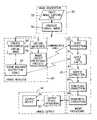
- FIG. 1is a block diagram of a digital image reproduction system according to the invention.
- FIG. 2is a functional block diagram of an image processing system illustrating the image analysis, image defect prediction, image processing (defect correction), and image output steps of the present invention
- FIG. 3is a logic diagram illustrating one technique of using data captured at the time of image capture to decide when to apply noise defect location and correction processes in digital image reproduction apparatus;
- FIG. 4is a logic diagram illustrating one technique of using data captured at the time of image capture to decide when to apply redeye defect location and correction processes in digital image reproduction apparatus;
- FIG. 5is a logic diagram illustrating one technique of using data captured at the time of image capture to decide when to apply tonescale defect location and correction processes in digital image reproduction apparatus;
- FIG. 6is a logic diagram illustrating one technique of using data captured at the time of image capture to decide when to apply sharpness defect location and correction processes in digital image reproduction apparatus.
- FIG. 7is a diagram illustrating a film camera adapted to write meta data on a photographic film.
- FIG. 8is a diagram illustrating a digital camera adapted to write meta data on a digital record.
- the programmay be stored in conventional computer readable storage medium, which may comprise, for example; magnetic storage media such as a magnetic disk (such as a floppy disk or a hard drive) or magnetic tape; optical storage media such as an optical disc, optical tape, or machine readable bar code; solid state electronic storage devices such as random access memory (RAM), or read only memory (ROM); or any other physical device or medium employed to store a computer program.
- magnetic storage mediasuch as a magnetic disk (such as a floppy disk or a hard drive) or magnetic tape
- optical storage mediasuch as an optical disc, optical tape, or machine readable bar code
- solid state electronic storage devicessuch as random access memory (RAM), or read only memory (ROM); or any other physical device or medium employed to store a computer program.
- Keelanand “ Use of System Image Quality Models to Improve Product Design ” by R. B. Wheeler, which are incorporated herein by reference, should be consulted for additional background information.
- the image quality scaleis based on just-noticeable-difference (JND) units of quality.
- JNDjust-noticeable-difference
- a JNDis defined as the smallest image quality difference that can be detected by 50% of observers in forced-choice (no ties allowed) paired image comparisons. Stated another way, when two images are separated by exactly one JND, 50% of human observers will perceive the quality advantage of the better image and rate it best. The other 50% of the human observers will not perceive the difference, but will guess correctly half the time.
- the preferred embodimentemploys a three JND (one-half quality category) criteria. This provides a reasonable balance between image quality enhancement and photofinishing throughput (images processed per unit of time). If the image quality switch-point is set at a lower JND value (e.g. one JND of degradation), the image defect location and correction processes will be invoked more frequently, which may lead to higher average image quality, but lower throughput due to extended image processing time. If the quality switch-point is set at a higher JND value (e.g. 6 JNDs of degradation), the image defect location and correction processes will be invoked less frequently, which may lead to lower average image quality, but higher throughput due to shortened image processing time.
- a lower JND valuee.g. one JND of degradation
- the quality switch-pointis set at a higher JND value (e.g. 6 JNDs of degradation)
- the image defect location and correction processeswill be invoked less frequently, which may lead to lower average image quality, but higher throughput due to shortened image processing time.
- image defect correction switch-pointsare defined that either activate or deactivate the image defect location and correction processes. It is to be understood that while this description pertains to correction processes that are applied in the same manner every time the quality loss due to an image defect is equal to or greater than the switch-point (e.g. 3 JNDs), the strength of the image defect correction processes can be altered in response to the degree of image quality loss predicted for the current scene.
- the switch-pointe.g. 3 JNDs
- the preferred embodiment of the present inventioncan be used to determine which image defect correction processes should be activated, and the strength of the corrections employed in those activated processes can be determined by analyzing the image pixel data using a series of pixel data predictors that correlate with the degree of the degradation caused by the defect. For example, the gradient of edges can be used to estimate the strength of the spatial filtering needed to correct sharpness defects.
- the inventive processuses information collected at the time of image capture, which is referred to as meta data, to predict the presence of image defects in a photograph, and to subsequently decide when to apply image defect correction processes in digital photofinishing.
- meta datadescribing the scene and camera conditions used to capture the current image, can be recorded by the camera and transferred to photofinishing equipment, as is described in commonly assigned U.S. Pat. No. 5,229,810, which is incorporated herein by reference.
- the information recording devicepreferably comprises a magnetic recording head for magnetically encoding data on the surface of the film.
- latent image bar code datamay be exposed outside the area of the primary image frame, and later decoded in the photofinishing equipment.
- other known data recording techniquesmay also be utilized such as optical or magnetic recording on separable media such as disks or integrated circuit cards.
- FIG. 1a general digital image processing system 10 useful in the practice of the invention is shown in which input pictorial image data and related image classification parameters are provided by means of one of a variety of indicated devices.
- the illustrated input devicesinclude a photographic film scanner 12 which optically scans the image frames on a film strip and converts the scanned signals into digital image data. If the scanner is capable of reading APS film, then the scanner will typically read from the magnetic layer or optical bar code on the film, information encoded in the APS meta data information exchange (IX) and manufacturer data areas.
- IXAPS meta data information exchange
- Such meta datamay include film type, camera settings, scene conditions, intended print format, and other data fields.
- image input devicesinclude a digital file reader 14 which may contain data from a variety of sources, including digital cameras or a picture disk reader, a network input (e.g. modem) 16 which receives digital file data from a remote, central source, as in the case of Kodak Picture Network, or an order entry station input device 18 located at a retail store which scans a customers film, reads digital disks, and accepts order instructions, including print aspect ratio, size, zoom, crop and magnification instructions.
- This datais then input to an image processing computer 40 which may also include a display monitor 22 and a user data input device such as a keyboard 24 .
- the key boardmay be used to input some of the scene, camera, and output size related data mentioned above.
- the image processing functions of the computer 40in accordance with the present invention is a process that makes use of camera, scene, and demographic factors to predict the presence of image defects in a photograph and subsequently to applies image defect correction means only when needed.
- the output of the image processing computer 40is applied to an appropriate output path for generation of hardcopy images.
- Representative output pathsare illustrated and include a printer 26 , such as a thermal dye printer or inkjet printer which are exemplary of printers useful for home computer use.
- the output pathmay comprise retail photofinisher equipment 28 , such as a Noritsu 2711 Series Printer.
- Yet another exemplary output pathcomprises data communications device 30 which communicates with, for example, a remote commercial photofinishing laboratory 32 using a CRT or other photographic printer.
- image processing system 10can be incorporated in an integrated apparatus such as a retail photofinisher unit.
- An important feature of the system shown in FIG. 1is the collection of meta data at the time of image capture indicating, or capable of indicating, whether a defect is likely to be present in the final viewed image. In the preferred embodiments, this is accomplished with data collected by either a film camera or a digital camera, although some of the meta data (e.g., demographic data and display parameters) could be collected at the order entry station 18 or some other location subsequent (or prior) to the time of capture.
- a film camera 200transports a film strip 201 between the reels 205 a,b of a film cartridge and a take-up sprocket respectively.
- the camera 200includes a magnetic read/write head 210 facing a magnetic layer on the unsensitized side of the film strip 201 .
- a microprocessor 215controls magnetic data recording or playback by the head 210 through head electronics 220 .
- the microprocessor 215may accept meta data to be magnetically recorded on the film strip 100 from the camera user or the camera mechanisms themselves through camera controls 225 , such information pertaining, for example, to the desired display parameters, lens parameters (e.g., focal length, F-number, camera lens focus range), shutter speed, autofocus distance measurements of subject and background, backlight and flash fire state indicators, and the like, for ultimate use by the photofinisher. If a suitable input device is provided, for example a keypad, demographic data could be generated at this time.
- the microprocessor 215may also accept scene related information from scene sensors 230 to be magnetically recorded on the film strip 100 for ultimate use by the photofinisher. Such information may include the ambient light level of the primary subject and background, and the like.
- the advantage of the longitudinal dedicated track formatis that magnetic recording of data on the film strip 201 may be performed by the camera using a relatively stationary head (i.e. the head 210 ) by buffering all of the data to be recorded in a particular frame in a particular camera track and then transmitting the data to the head just as the film is being wound to the next frame.
- a relatively stationary headi.e. the head 210
- the microprocessor 215includes a read only memory 240 containing instructions sufficient to ensure that each type of information received is recorded in the correct one of the dedicated camera tracks in accordance with a universal pre-arrangement common to both the camera and the photofinisher.
- the aforementioned APS information exchange (IX) specificationsillustrate dedicated camera tracks for meta data storage and information exchange. Section 10, “Writing and Reading Magnetic Information”, and more specifically Section 10.4 “Data Dictionary”, contain the relevant information.
- the microprocessorsorts and buffers each piece of information in compliance with the instructions stored in the read only memory 240 .
- the microprocessoralso includes a ROM 250 with other camera-specific data, such as main flash and preflash guide number and camera to flash separation (if the flash is integral with the camera), lens-specific data (e.g., focal length and focus range, if the lens is integral with the camera), and the like, as well as a RAM 260 for storing film-specific information read from the film cassette, such as film ISO speed read from the DX coding on the film cassette.
- the meta data in the ROM 250 and the RAM 260is then magnetically recorded on the film strip 100 for ultimate use by the photofinisher.
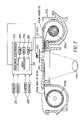
- a digital camera 300includes a lens 340 that directs image light from a subject (not shown) through an aperture/shutter controller 341 and an anti-aliasing filter 342 upon an image sensor, which is typically a CCD or CMOS sensor 344 .
- the sensor 344generates an image signal that is processed by an analog video processor 346 before being converted into a digital image signal by an analog to digital (A/D) converter 348 .
- the digitized image signalis temporarily stored in a frame memory 350 , and then compressed by a digital signal processor 352 .
- the compressed image signalis then stored in a data memory 354 or, if a memory card 356 is present in a memory card slot of the camera, transferred through a memory card interface 358 to the memory card 356 .
- the memory cardis adapted to some appropriate interface standard, such as the PCMCIA card interface standard as described in the PC Card Standard, Release 2.0, published by the Personal Computer Memory Card International Association, Sunnyvale, Calif., September, 1991.
- the card interface 358 and the card connector 359provide, e.g., an interface according to the aforementioned PCMCIA card interface standard.
- the compressed image signalmay also be sent to a host computer, which is connected to the camera 300 through a host computer interface 360 .
- a camera micro-processor 362receives user inputs 364 , such as from a shutter release, and initiates a capture sequence by triggering a flash unit 366 (if needed) and signaling a timing generator 368 .
- the timing generator 368is connected generally to the elements of the camera 300 , as shown in FIG. 8 , for controlling the digital conversion, compression, and storage of the image signal.
- the microprocessor 362also processes a signal from a scene sensor (photodiode) 370 for determining a proper exposure, and accordingly signals an exposure driver 372 for setting the aperture and shutter speed via the aperture/shutter controller 341 .
- the CCD sensor 344is then driven from the timing generator 368 via a sensor driver 374 to produce the image signal.
- the microprocessor 362may accept meta data to be recorded on the digital record from the camera user inputs 364 or from camera mechanism inputs 380 , such information pertaining, for example, to the desired display parameters, lens parameters (e.g., focal length, F-number, camera lens focus range), shutter speed, autofocus distance measurements of subject and background, backlight and flash fire state indicators, and the like, for ultimate use by the photofinisher.
- the user inputs 364can also include the resolution setting and gain factor of the camera (number of pixels in the captured image and the sensor-based ISO speed, if such is settable).
- the microprocessor 362may also accept scene related information from the scene sensors 370 to be recorded on the digital record for ultimate use by the photofinisher. Such information may include the ambient light level of the primary subject and background, and the like.
- the microprocessor 362may also accept camera shake data (measure of handheld stability of the camera) from a shake sensor 382 .
- Certain camera meta datamay be contained in the camera PROM 328 , which is connected to the digital signal processor 352 .
- the camera PROM 328includes camera-specific data, such as main flash and preflash guide number, camera to flash separation, sensor ISO speed, resolution setting, camera shake factor, and the like.
- camera-specific datamay be variable (for example, if the flash unit is separable, movable, or otherwise adjustable) or invariant (for example, if the flash is non-movable and integral with the camera).
- the sensor ISO speedmay be the base ISO speed and the resolution setting may be the native setting, if this data is invariant.
- Different data structuresmay be used to transfer the meta data and the image data from the camera.
- the digital signal processor 352may write the meta data into a camera header, followed by individual image trailer records.
- the meta datais written into individual camera headers together with individual image trailer records.
- certain of the meta data, such as the camera-specific data stored in the PROM 328may be contained in a computer file 330 (instead of, or in addition to being, in the PROM 328 ), which is provided as a floppy disk or the like in combination with the camera 300 .
- This meta datais then accessed by the host computer through a conventional disk drive interface (not shown) when the user loads the disk into the interface.
- the meta datamay also be embedded with the image data in a form of digital watermarking, e.g., as taught in U.S. Pat. No. 6,044,156, entitled “Method for Generating an Improved Carrier for Use in an Image Data Embedding Application”, which is incorporated herein by reference.
- meta data creationin connection with film and digital cameras that other forms of meta data pertaining to camera, scene, demographic and display factors would be known to those of skill in this art, and are intended to be within the ambit of this invention.
- other structures and mechanisms for the transfer of such meta data to subsequent utilization devices, such as digital photofinisherswould be clear to the skilled person and are intended to be within the scope of this invention.
- the capture devicesare described as film and digital cameras, it is possible that other capture devices such as a linear or area scanner could benefit from the invention, and to that extent are also included within the inventive concept.
- the camera, scene or demographic factorscan be directly recorded on the output medium, or the microprocessor 215 (film) or 362 (digital) may be employed to perform image processing upon the factors, for instance to determine if the current image will have a level of defect that if left untreated would reduce the perceived quality of the final viewed image. Consequently, in the latter case, the microprocessors 215 and 362 may perform some, or all, of the image processing performed by the digital image processor 40 shown in FIG. 1 , that is, to predict the presence of image defects in a photograph and subsequently to enable image defect correction means only when needed.
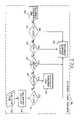
- FIG. 2represents a functional block diagram of a digital photofinishing system
- the image acquisition block 50includes image data and meta (e.g. APS IX) data from a capture device 52 such as the conventional photographic film camera 200 shown in FIG. 7 for recording a scene on color negative or reversal film, and a film scanner device for scanning the developed image on the film and producing a source digital image 56 and extracting the image meta data.
- a capture device 52such as the conventional photographic film camera 200 shown in FIG. 7 for recording a scene on color negative or reversal film, and a film scanner device for scanning the developed image on the film and producing a source digital image 56 and extracting the image meta data.
- a capture device 52such as the conventional photographic film camera 200 shown in FIG. 7 for recording a scene on color negative or reversal film
- a film scanner devicefor scanning the developed image on the film and producing a source digital image 56 and extracting the image meta data.
- Another example of an image capture device 52is the digital camera 300 shown in FIG. 8
- the formed digital image file and associated meta datais transferred to the image analysis block 60 , where the meta data decoder 66 extracts the information to be used in the image defect prediction process block 68 .
- the primary purpose of the image defection correction process block 68is to analyze available meta data pertaining to camera, scene, demographic, and image display factors, predict the presence of image defects in the final image display, and subsequently to activate only those correction processes in image processing block 70 that will improve the quality of the current image.
- image analysis 60Prior to providing a detailed description of image defect prediction process block 68 , the other functions of the image analysis 60 , image processing 70 , and image output 90 blocks will be described.
- the full resolution digital image containing the red, green, and blue pixel datais subsampled in block 62 to create a smaller, for example 24 ⁇ 36 pixel, image that is analyzed by the scene balance algorithm 64 .
- Scene balance algorithmsuse analog or digital processing to obtain the correct color balance and overall lightness for each image. The algorithms are commonly known as “white-balance,” “color-constancy” or “scene-balance” algorithms. These algorithms can work on a single image, several images, or an entire set of images.
- An example of a suitable scene balance algorithmsis described by E. Goll et al., “ Modern Exposure Determination for Customizing Photofinishing Printer Response ”, Journal of Applied Photographic Engineering, 2, 93 (1979), which is incorporated herein by reference.
- the present inventionmay be practiced with any scene balance module such as the one described by Cok et al. in U.S. Pat. No. 4,945,406, which is incorporated herein by reference.
- the scene balance modulecalculates the pixel values of a theoretical 20% gray card corresponding to the exposure of the scene digital image.
- a look-up-tableis calculated and applied to the scene state digital image, which results in a balanced digital image.
- no scene balance moduleperforms perfectly at the task of compensating the digital image for variations in exposure and illumination color effects, the scene balance module does improve the accuracy of the color representation of the digital image.
- the scene balance algorithmis needed for nearly all images, due to imperfections in image capture exposure and/or illuminant color balance, and the scene balance algorithm is computationally efficient, due to the use of a smaller subsampled image, it is applied to every image in the preferred embodiment of the present invention.
- the remaining image processing stepswhich are located in the image processing block 70 , are selectively applied based on the output of the image defect prediction process 68 .
- the digital image produced in block 56is provided in separate chrominance and luminance channels, as needed, for the subsequent image processing steps.
- the noise correction process 72is applied prior to the scene balance shift 76 to make use of the unbalanced color channel specific exposure information of the capture.
- the Sigma filterdescribed by Jong-Sen Lee in the aforementioned journal article Digital Image Smoothing and the Sigma Filter , which is incorporated herein by reference, is a noise reduction algorithm to enhance the visual appearance of the processed digital image.
- the values of the pixels contained in a sampled local region, n by n pixels where n denotes the length of pixels in either the row or column direction,are compared with the value of the center pixel, or pixel of interest.
- Each pixel in the sampled local regionis given a weighting factor of one or zero based on the absolute difference between the value of the pixel of interest and the local region pixel value. If the absolute value of the pixel value difference is less or equal to a threshold, the weighting factor is set to one. Otherwise, the weighting factor is set to zero.
- p ij1 if
- p ijrepresents the ij th pixel contained in the sampled local region
- p mnrepresents the value of the pixel of interest located at row m and column n
- a ijrepresents a weighting factor
- q mnrepresents the noise reduced pixel value.
- a rectangular sampling region centered about the center pixelis used with the indices i and j varied to sample the local pixel values.
- the parameter Sfacis termed a scale factor can be used to vary the degree of noise reduction.
- the calculation of the noise reduced pixel value q mn as the division of the two sumsis then calculated. The process is completed for some or all of the pixels contained in the digital image channel and for some or all the digital image channels contained in the digital image.
- the noise reduced pixel valuesconstitute the noise reduced digital image.
- a median filtermay also be used as a noise reduction algorithm to reduce the noise present in a digital image.
- the noise reduced pixel value produced with a median filteris typically derived by calculating the statistical mean of values taken from a sampling region centered about the pixel of interest.
- an n by n square window sizeis chosen where n denotes the length of pixels in either the row or column direction.
- the degree of noise reductionis controlled by the size of the window. Larger window sizes result in more noise removed from the digital image.
- the redeye correction process 80locates and removes eye color defects.
- the present inventionmay be practiced with a variety of methods which locate and correct redeye defects.
- One suitable methodis disclosed by Benati et al. in U.S. Pat. No. 5,748,764, which issued May 5, 1998 and which is incorporated herein by reference. This method locates redeye defects in an image and provides separate corrections for body, border, and glint pixels in the pupil of the affected eye.
- the redeye defect detection processinvolves defining a spatial region within the digital image in which one or more eye color defects may exist, which includes at least a portion of the subject's head; sampling the color content of the pixels within the spatial region and comparing the sampled pixels with threshold values indicative of redeye defect pixels; segmenting the potentially defective pixels into contiguous groups; calculating a first score for each pixel of each group based on a plurality of features including group size, group shape, coloration, and brightness to identify redeye defect candidates; selecting a seed pixel based on its score from each identified eye color defect group candidate and determining all of the neighboring pixels which are within a predetermined score range of their neighboring pixels and those pixels which represent a significant pixel score transition indicative of the outer boundary of the redeye defect.
- Each of the three redeye defect pixel typesis rendered differently to remove the defect and create a natural appearing correction.
- An alternative embodiment of the present inventionemploys a method of applying a redeye defect location and correction process disclosed by Schildkraut et al. in commonly-assigned U.S. Pat. No. 6,292,574 issued Sep. 18, 2001, entitled A Computer Program Product for Redeye Detection .
- This processis advantageously used in conjunction with the method disclosed in commonly-assigned U.S. Pat. No. 6,151,403 issued Nov. 21, 2000 entitled Method for Automatic Detection of Human Eyes in Digital Images by Jiebo Luo. Both patents are incorporated herein by reference.
- photographic imageswhich have a luminance dynamic range that far exceeds the dynamic range of conventional display systems.
- photographic images taken in sunny outdoor conditionscan have 10 or more photographic stops of recorded information while photographic paper can reproduce approximately seven photographic stops of information.
- electronic flash illuminationby virtue of the distance-induced exposure difference between the main subject and background, can also produce dynamic range that exceeds the capacity of the chosen display.
- scene dependent tone scale function algorithmsmay be employed to reduce the dynamic range of the source digital image thus providing a better match of the processed digital image to the dynamic range capabilities of the output medium.
- the scene dependent tonescale correction process 84uses the pixels in the balanced digital image to calculate a tone scale function, i.e., a single valued mathematical equation or transformation that has a single output value corresponding to each input value.
- the present inventionimplements the tone scale function as a look-up-table for computation efficiency.
- the result of the application of the tone scale processingproduces a tone scale adjusted digital image such that the tone scale, or brightness and contrast, of the digital image is enhanced without modification of the color content.
- the present inventionmay be practiced with a variety of methods that generate tone scale functions.
- the preferred embodiment of the present inventionuses the methods disclosed in U.S. Pat. Nos. 4,731,671 and 5,822,453, which are both incorporated herein by reference. These methods are employed by the present invention to produce two individual tone scale functions. These two tone scale functions are then cascaded into single tone scale function which is used to adjust the brightness and contrast of the balanced digital image.
- Lee and Kwondisclose a method of calculating a tone scale function using the pixel values of a digital image, and involving the estimation of the scene contrast from the digital image.
- the method taught by Lee and Kwoninvolves calculating a Laplacian filtered version of the digital image, forming a histogram of the Laplacian signal; determining from the Laplacian histogram two threshold values which when applied to the Laplacian signal substantially eliminate uniform areas; sampling pixels from the digital image which are based on the thresholds; forming a histogram from the sampled pixels; computing a standard deviation of the sampled histogram; and estimating contrast of the digital image by comparing the computed standard deviation with a predetermined contrast for determining contrast of the input image in relationship with the predetermined contrast.
- the method described by Lee and Kwonis used to calculate a first tone scale function.
- Alkoferdiscloses a method of calculating a tone scale function using the pixel values of a digital image based on normalizing the histogram of a digital image. This method involves determining the contrast of the digital image by calculating the standard deviation of a sample of pixel values. The second tone scale function is calculated by normalizing a histogram of the sample of pixel values. The sample of pixel values is selected from one of a plurality of samples of pixel values corresponding to a plurality of contrast intervals based upon the shape of the histogram of the selected sample of pixel values. To facilitate the adjustment of contrast, the tone scale function is constructed to produce values in units of a standard normal variate Z. These Z values are then multiplied by a constant, which is a function of the standard deviation of the sample of pixel values to determine the contrast of the processed digital image.
- the j variablerepresent the index of pixel values of the digital image to be processed.
- the final tone scale function LUT fis calculated by evaluating the expression of equation 3 for the range of possible pixel values.
- the final tone scale function LUT f and the balanced digital imageis received by the tone scale correction block 84 .
- the present inventionapplies the final tone scale function to the luminance digital image channel of the balanced digital image to adjust the brightness and contrast attributes of the digital image.
- the preferred embodiment of the present inventionapplies the final tone scale function, in the form of a look-up-table, directly to the pixels of the luminance digital image channel of the balanced digital image. This method is preferred primarily for its computational efficiency properties.
- An alternative embodiment of the present inventionemploys a method of applying a tone scale function disclosed by Lee et al. in U.S. Pat. No. 5,012,333, which is incorporated herein by reference, for improved image quality results.
- Lee et al.describe a method for interactively modifying image attributes
- the present inventionemploys the method of applying tone scale functions to digital images based on spatial filtering techniques. This method involves spatially filtering the luminance digital image channel resulting in two spatial frequency components (high and low frequency components), applying the tone scale function to the low spatial frequency component, and combining the tone scale modified low spatial frequency component with the high spatial frequency component.
- This approachemploying frequency separable tone scale manipulation and sharpening, is superior to methods such as those disclosed in U.S. Pat. No. 5,739,924, which involve emphasizing the outline and the contrast of the subject based on subject brightness, and subject distance.
- the sharpness correction process 88receives the tone scale adjusted digital image from the tone scale module 84 and applies a spatial filter to the tone scale adjusted digital image to adjust spatial modulation content.
- the present inventionmay be practiced with a variety of different spatial filters; however, a key aspect of the present invention relies on the combination of the method of manipulation of the color, tone and spatial detail attributes of a digital image.
- An example of a spatial filter that may be usedis described by Kwon et al. in U.S. Pat. No. 5,398,077, which is incorporated herein by reference.
- Kwon et alteach a method of spatially processing a digital image involving transforming a red-green-blue image into a luminance chrominance domain and applying an adaptive filter to the luminance channel.
- the adaptive filteremploys a method of calculating a statistical measure of local spatial activity and varying the sharpness of the image detail structure based on the statistical measure.
- the result of the application of the spatial filterproduces a tone scale adjusted digital image with modified values such that the spatial detail of the digital image is enhanced without modification of the color content.
- the image output block 90receives the modified digital image from the sharpness correction block 88 .
- the digital image processing steps conducted within the output device rendering block 92involve transforming the pixel values of the modified digital image into a corresponding set of device code values to account for the color manipulation characteristics of the output device and media.
- the transformation between device code values and the colorimetry of the colors reproduced by a particular device/media combinationcan be obtained by a device characterization.
- An example of a device characterizationis a procedure that involves generating and printing or displaying a suitable array of device code values in the form of color patches of a size large enough for subsequent measurement. These patches can be measured using a calorimeter, a spectrophotometer or a telespectroradiometer, depending on the nature of the display.
- CIE XYZ values and other related quantitiessuch as CIELAB or CIELUV values can be calculated for the display illuminant using standard calorimetric procedures.
- This data setcan be used to construct the appropriate sequence of one-dimensional look-up tables, multidimensional look-up tables, matrices, polynomials and scalars that accomplishes that transformation of the digital representation of the scene resulting from the combined processing operations performed in the output device rendering block 92 into a set of device code values that produces this desired visual representation of the scene.
- Another example of the implementation of this transformationis an ICC profile that maps the specifications of the desired visual reproduction, encoded in profile connection space (PCS), to device code values.
- PCSprofile connection space
- This operationmay also include gamut mapping.
- the color gamut characteristics of the modified digital imageare determined by the set of primaries that was used for encoding the data. Examples include the primaries corresponding to the color-matching functions of the CIE 1931 Standard Colorimetric Observer or any linear combinations thereof.
- Gamut mappingis performed between the gamut defined by this encoding and the gamut of the output device/media combination.
- the preferred gamut mapping algorithms used in combination with this inventionare those that maintain hue.
- the data transformation performed by the output device rendering block 92can be combined to form a single set of one-dimensional look-up tables, multidimensional look-up tables, matrices, polynomials and scalars in any sequence.
- Reproductions according to the specifications of this inventioncan be produced by a variety of technologies. Reproductions can be obtained on silver halide or other light-sensitive materials.
- the light-sensitive materialmay be transparent film, reflective paper, or semi-transparent film. These materials are exposed by visible or infrared light derived from many different sources. The materials may be designed for typical photofinishing applications or they may be specially designed for digital printing applications.
- the photo-sensitive materialsrespond primarily to three different spectral regions of incident light. Typically, these are red (600–720 nm), green (500–600 nm), and blue (400–500 nm) light. However, any combination of three different spectral sensitivities can be used. These could include green, red, and infrared light or red, infrared 1, and infrared 2 light, or 3 infrared lights of different wavelengths.
- a material sensitive to the three primary wavelengths of visible lightmay be false sensitized so that the color of the exposing light does not produce image dye of the complementary hue, such as red, green, and blue sensitivity producing magenta, yellow, and cyan dye, respectively.
- Printingcan be effected by exposing all pixels sequentially, by exposing a small array of pixels at the same time, or by exposing all the pixels in the image at the same time.
- Devices which can be used to print on light-sensitive materialsinclude CRT, LED (Light Emitting Diode), LVT (Light Valve Technology), LCD, Laser, as well as any other controlled optical light generating device. All these devices have the ability to expose 3 or more light-sensitive layers in a light-sensitive material to produce a colored image. They differ mainly in the technology on which the devices are based.
- a suitable embodiment of a CRT printeris the Kodak Digital Science LF CRT Color Printer which can be used in combination with Kodak Professional Digital III Color Paper.
- Non-light-sensitive imaging materialsare conveniently used by electronic printing processes to produce high-quality reproductions.
- the printing processcan be based on many technologies.
- the method of image formationcan be half-tone, continuous tone, or complete material transfer.
- the imaging materialcan be transparent film, reflective paper, or semi-transparent film.
- the materialscan be written on to produce pictorial images by thermal dye transfer, ink jet, wax, electrophotographic, or other pixelwise writing techniques. These processes use three or more colorants to create colored pictorial representations of pictorial scenes.
- the colorantsmay be dyes, toner, inks, or any other permanent or semi-permanent colored material.
- a suitable embodiment of a thermal printeris the Kodak XLS 8650 thermal dye transfer printer.
- imagescan also be created by optically projecting the image in the form of light rays from behind or in front of the viewer toward a screen which is in front of a viewer or by projecting a reversed image toward the viewer onto a screen between the viewer and the projecting device.
- a suitable embodiment of a CRT displayis a Sony Trinitron CRT.
- a number of intermediate parametersare calculated in the image defect prediction block 68 from the decoded data and subsequently used in the Noise Defect Prediction Block 100 shown in FIG. 3 , the Redeye Defect Prediction Block 120 shown in FIG. 4 , the Tonescale Defect Prediction Block 140 shown in FIG. 5 , and the Sharpness Defect Prediction Block 160 shown in FIG. 6 .
- Other parameterssuch as Flash Fire State (on/oft) can be used directly, and still other parameters may require units conversion; for example, ambient light level, which is converted from camera BV (brightness value) to luminance units in foot lamberts.
- the intermediate parameter values, calculated from decoded meta data, and used in multiple defect prediction blocks,are calculated once and shared among the defect prediction blocks 100 , 120 , 140 , 160 .
- the processing steps ( 104 , 124 , 144 , 164 ) that follow the meta data input blockshow the creation of each of the intermediate parameters.
- This sectiondefines the meta data items and shows the manner in which the intermediate parameters are calculated from the meta data items in the preferred embodiment.
- the units of distance, exposure, flash output, system magnification, and image defect levelcan be recast without departing from the intent of the teachings of the present invention.
- the following meta data items, or a subset thereof, collected by camera sensors and/or manual photographer inputare employed in the image defect prediction blocks ( 100 , 120 , 140 , 160 ):
- a number of intermediate parametersare calculated from the meta data listed above and employed in the image defect prediction blocks ( 100 , 120 , 140 , 160 ).
- the intermediate parameters quantifying the degree of exposure of the main subject and the background, which have been found to be useful in the noise defect prediction 100 and tonescale defect prediction 140 blocks,are calculated as follows:
- the flash and ambient exposures for the backgroundare calculated in the same fashion, but in this case the measured camera-to-background distance data and background illuminance levels are used in the equations.
- LLn(EQ. 6) is defined as the light level (foot lamberts), in this case for the background portion of the scene, where an ISO normal exposure occurs with the current camera settings.
- FERFlash Exposure Ratio
- AERAmbient Exposure Ratio
- the absolute value signsare needed in the exponent term of EQ. 9 and EQ. 10 to reflect the fact that the magnitude of the exposure ratio, whether the subject or background is receiving the dominant exposure, is the key parameter.
- the intermediate parameters quantifying the format and subject reproduction magnifications as perceived in the final display, which have been found to be useful in the Noise Defect Prediction Block 100 , the Redeye Defect Prediction Block 120 , and the Sharpness Defect Prediction Block 160 ,are calculated as follows:
- the AM parameterhas been found to be a useful predictor for determining the maximum handheld shutter time required to minimize hand-tremor-induced blur for the average photographer.
- the AMis a useful predictor in that it correlates with the size of the subject's eyes, and therefore contributes to the perceived severity of the redeye image defect.
- AM[( FL )( Mc )]/ Vd EQ. 11 Where: Vd: Final Image Viewing Distance (Specified in Inches)
- the maximum handheld shutter timeis an intermediate parameter that specifies for the current camera lens focal length, reproduction magnification, and final image viewing distance, the longest handheld shutter time that can be employed by a person with average hand tremor with out causing noticeable blur to be perceived in the final image.
- the MSTis affected by the camera shake factor (CSF), which specifies the stability of the camera.
- CSFcamera shake factor
- the CSFis one of the items that may be included in the general camera meta data. If the CSF is not available, the default value of unity, appropriate for typical 35 mm point-and-shoot cameras is used.
- SLRinterchangeable lens
- MST[ (0.169)( Vd )( CSF )]/[( FL )(25.4)( Mc )] EQ. 13
- the constant 0.169is needed to fit the experimental data such that the result of the MST equation is the longest exposure time that will not produce significant image blur.
- the value of this constantwas derived by rating the quality of images shot by a representative population of photographers, where the exposure times were systematically varied.
- the constant 25.4converts the camera lens focal length from inches to mm.
- the present authorsdisclose the Display Size Factor (DSF) in columns 44–45 of the aforementioned U.S. Pat. No. 5,323,204, which quantitatively accommodates the independent selection of display size and reproduction magnification.
- the DSFwas conceived in order to account for the differences between full-frame reproductions and cropped image reproductions where the final display size is not the product of the capture media format size and the reproduction magnification. This occurs when pseudo-panoramic or pseudo-telephoto (electronic zoom) features, which are popular on APS and DSC cameras, are selected by the photographer and/or when a device such as a Kodak Picture Maker is used to selectively zoom and crop a portion of a full-frame image to create a new composition.
- pseudo-panoramic or pseudo-telephoto (electronic zoom) featureswhich are popular on APS and DSC cameras
- the DSF parameteris used in the Noise Defect Prediction Block 100 to create lookup tables for decision point 106 , and in the Sharpness Defect Prediction Block 160 at decision point 166 .
- the DSFdecreases when the reproduction magnification increases and the viewing distance decreases.
- the full-frame 8 ⁇ 12 inch case and the 2 ⁇ EZ 4 ⁇ 6 inch print casehave the same reproduction magnification (Mn), but the 2 ⁇ EZ case produces a smaller print and therefore a closer viewing distance that leads to a smaller DSF, which correlates with lower perceived image quality.
- each of the image defects included in the inventive processwas studied to determine the relationship between the amount of defect present and the perceived image quality loss.
- the image quality loss datawas correlated with scene, camera, demographic, and display parameters to develop the predictors employed in Image Defect Prediction Blocks 100 , 120 , 140 and 160 , which were found to be useful in determining when to activate the digital image defect correction processes contained in Blocks 72 , 80 , 84 and 88 .
- the empirical studies leading to the development of the predictorsinvolved the generation of images of a variety of scene types containing camera, illumination, display, and subject characteristics spanning the range encountered in consumer photography. By varying the imaging system and scene characteristics in this fashion, a population of images containing a wide range of image defects was produced. These images were visually rated for quality using the perceptually uniform JND scale previously described, and their associated capture and display characteristics were analyzed to develop the final parameters suitable for predicting the probability and severity of image defects.
- the predictor valueshereafter denoted as switch-point (SP) values, are selected for each decision point parameter 106 , 128 , 130 , 132 , 148 , 152 , 166 , 170 , 172 , 174 that correspond with 3 JNDs of image quality loss.
- SPswitch-point
- the 3 JND valuewhich corresponds with about one-half of a subjective image quality category, was selected for the preferred embodiment because it provides a good balance between image processing efficiency (number of images processed per unit time) and image quality improvement.
- the SP values in the tableshould cover the range of conditions encountered in consumer photography.
- Image Defect Prediction Blocks 100 , 120 , 140 and 160A detailed description of the processes contained in Image Defect Prediction Blocks 100 , 120 , 140 and 160 will now be provided. To illustrate the functionality of the Image Defect Prediction Blocks in the preferred embodiments of the present invention, SP parameter values for traditional film (e.g. AgX-based media) will be shown. However, it should be appreciated that the inventive image defect prediction processes are equally applicable to other capture media, whether based on chemical or electronic capture technologies. In the description that follows, the points in the process where specific parameter values vary depending on the image capture modality will be highlighted.
- traditional filme.g. AgX-based media
- FIG. 3Noise Defect Prediction Block 100
- Block 102Meta Data Input List
- an SP value substantially below any obtainable by the systeme.g. ⁇ 100
- an SP value substantially above any obtainable by the systemis entered in the table.
- Table 1shows the Es (log 10 Exposure units) SP values for three display sizes and three film speeds.
- the SP Tableincludes all of the DSF possibilities for the particular image processing apparatus. For example, some digital printers may only produce prints with fixed magnifications, as shown in the current example, while others may offer a wide range of print sizes and intermediate zoom ratios. In these more versatile printers, the Noise SP Table preferably contains DSF entries corresponding to each print size and zoom magnification. Alternatively, intermediate SP values can be obtained by interpolating between values in the table.
- the Noise SP Table for digital still camerasalso varies with respect to DSF; however, rather than loading in films with different sensitivities, as shown above, the photographer or camera exposure control selects a Digital Gain Factor (DG) appropriate for the current scene. Therefore, the DSC Noise SP Table lists DSF versus DG.
- the 3 JND quality loss values populating the DSC Noise SP Tablecan be derived with the empirical photographic testing and perceptual evaluations referenced above, alternatively, the values can be generated using the methods referenced by the present inventors in the aforementioned articles entitled “ Characterization and Prediction of Image Quality” by B. W. Keelan, and “ Use of System Image Quality Models to Improve Product Design” by R. B. Wheeler.
- FIG. 4Redeye Defect Prediction Block 120
- Block 122Meta Data Input List
- the severity of redeyeis a strong function of demographic classification of the subject photographed, due to two effects.
- the SP Tables employed in Redeye Defect Prediction Block 120 at points 128 , 130 and 132may contain different values depending on the demographic characteristics supplied. If no demographic data is available, the SP Tables for Caucasian Adult, which are shown hereafter in the preferred embodiment, are used as the default.
- the flash-to-lens separationhas a significant impact on the level of redeye defect.
- FLSis a fixed value in most cameras (flash is stationary); therefore, the SP Tables employed in Redeye Defect Prediction Block 120 at points 128 , 130 and 132 would typically contain SP values derived from the quality evaluation of images produced with the FLS of the current camera.
- the current inventionemploys a separate SP Table for each FL (zoom setting) selected by the photographer.
- Table 3shows the affect of FLS on image quality (JNDs) for the following system: Caucasian adult population; 0.5 foot lamberts ambient light; subject distance 10 feet; no preflash; unit angular magnification; normally viewed 4 ⁇ 6 inch print from 35-mm format film.
- the SP Tables employed in Redeye Defect Prediction Block 120 at points 128 , 130 and 132are loaded with values that correspond to the specific FLS value supplied in the meta data.
- Empirical studiesshow that the quality loss due to the redeye image defect is greatest at an intermediate camera-to-subject distance (Ds), which falls within the range commonly occurring in consumer photography. This is due to the competition of two opposing effects: (1) At longer camera-to-subject distance, the angular separation of the flash and lens is reduced, leading to greater red saturation of the pupil, and, (2) At longer distances, the pupil size in the final image is diminished, reducing redeye severity. To a crude approximation, as distance increases, the redeye becomes more intensely red but the pupil size in the image decreases. The former effect dominates at short distances and the latter at longer distances, leading to an extremum in the relationship at intermediate distances.
- Dscamera-to-subject distance
- the SP Tables employed in Redeye Defect Prediction Block 120 at points 128 , 130 and 132 in the preferred embodimentare populated with values corresponding to the critical camera-to-subject distance, which is defined as the distance producing the most severe defect level. This approach ensures that Redeye Correction Process 80 is applied when the probability of redeye is high but Ds meta data is not available. If Ds meta data is available, and added predictive accuracy is desired, SP Tables for each distance can be advantageously applied.
- Block 124Processes
- Table 4shows SP value (LL in foot Lamberts) for the critical distance for each FLS with AM at 1.5, which is a demanding case of the sort found on typical 3 ⁇ zoom cameras. If FLS is not supplied in meta data, a value of one inch (smallest separation found on consumer cameras) is assumed.
- Block 130Decision Point
- Table 5shows SP value for FLS of 1.0 inches and the critical distance for each AM. If LL is not supplied in meta data, a value of 0.2 foot lamberts is assumed.
- Block 132Decision Point
- Table 6shows SP value for FLS of 1.0 inches, at the minimum light level for typical flash pictures (0.2 foot lamberts), and the critical distance for each AM.
- the AMis above 1.2, the preflash guide number (GNp) values needed to produce less than 3 JNDs of quality loss indicate higher output than is typically found on consumer cameras; whereas, when the AM is below 0.43, the quality loss due to the redeye defect will be less than 3 JNDs with no preflash applied.
- GNppreflash guide number
- FIG. 5Tonescale Defect Prediction Block 140
- Block 142Meta Data Input List
- tonescale correction process 156executes tonescale correction process 156 .
- Block 152Decision Point
- AER and FERThe preferred value for AER and FER was derived from a review of numerous images with a wide range subject and background exposure ratios, together with learning from the optimization of fill-flash algorithms, as disclosed by the present inventors in columns 50–58 of the aforementioned U.S. Pat. No. 5,323,204.
- the SP value of 2.8was selected because we found that it provides a reasonable balance between image quality enhancement and photofinishing throughput (images processed per unit of time). If the values for AER and FER are set to a lower JND value, the tonescale image defect location and correction processes will be invoked more frequently, which may lead to higher average image quality, but lower throughput due to extended image processing time. If the values for AER and FER are set to a higher JND value, the image defect location and correction processes will be invoked less frequently, which may lead to lower average image quality, but higher throughput due to shortened image processing time.
- FIG. 6Sharpness Defect Prediction Block 160
- the image defect prediction processes 100 , 120 , 140 , 160have shown the preferred embodiments, but it is to be understood that they may be advantageously applied, even if all of the data is not available.
- the hierarchyis purposefully set so the most readily available data is required earliest in each process, and if data is missing, the decision of the last block containing data has priority. For example, if after the first decision point, the data suggests that there is a probability of an image defect, but no additional data is available, the defect correction process will be executed. This is acceptable, because a “mistake” based on omission of data, simply means that a defect correction may be occasionally applied when not needed. This will not reduce the image quality, but merely lead to a slight reduction in the throughput advantage produced by the preferred embodiment.
Landscapes
- Engineering & Computer Science (AREA)
- Multimedia (AREA)
- Signal Processing (AREA)
- Image Processing (AREA)
- Facsimile Image Signal Circuits (AREA)
- Studio Devices (AREA)
- Television Signal Processing For Recording (AREA)
Abstract
Description
AM=[(Fl)(Mr)]/Vd
Where:
- Fl=camera lens focal length (specified in inches)
- Mr=reproduction magnification (ratio of image to display size)
- Vd=final image viewing distance (specified in inches)
Vd=3.64+11.34[log10(D)]
Where:
- D=the diagonal dimension of the final display (specified in inches)
qmn=Σijaijpij/Σijaij EQ. 1
and
aij=1 if |pij−pmn|<=ε
aij=0 if |pij−pmn|>ε
where pijrepresents the ijthpixel contained in the sampled local region, pmnrepresents the value of the pixel of interest located at row m and column n, aijrepresents a weighting factor, and qmnrepresents the noise reduced pixel value. Typically, a rectangular sampling region centered about the center pixel is used with the indices i and j varied to sample the local pixel values.
ε=Sfac σn(pmn) EQ. 2
where σnrepresents the noise standard deviation of the source image evaluated at the center pixel value pmn. The parameter Sfac is termed a scale factor can be used to vary the degree of noise reduction. The calculation of the noise reduced pixel value qmnas the division of the two sums is then calculated. The process is completed for some or all of the pixels contained in the digital image channel and for some or all the digital image channels contained in the digital image. The noise reduced pixel values constitute the noise reduced digital image.
LUTf=LUT1[LUT2[j]] EQ. 3
where LUT2represents the second tone scale function, LUT1represents the first tone scale function, and LUTfrepresents the final tone scale function. The j variable represent the index of pixel values of the digital image to be processed. The final tone scale function LUTfis calculated by evaluating the expression of equation 3 for the range of possible pixel values.
- Subject Demographic Data includes: subject race and age
User-Specified or Camera-Measured Parameters: - BL: Camera Backlight Indicator State (on/off;on=high contrast scene)
- CSF: Camera Shake Factor (measure of handheld stability of camera)
- D: Diagonal Dimension of the Final Display (inches)
- DG: DSC Gain Factor (multiple of sensor base ISO speed)
- DR: DSC Resolution Setting (number of pixels in captured image)
- Ds: Camera-to-Subject Distance (feet)
- Db: Camera-to-Background Distance (feet)
- f: Camera Lens F-number
- FL: Camera Lens Focal Length (inches)
- FF: Flash Fire State (on/off)
- FLS: Flash-to-Camera Lens Separation (center-to-center, inches)
- GNm: Main Flash Output (Guide Number, Current ISO, feet)
- GNp: Preflash Output (Guide Number, Current ISO, feet)
- K: ANSI Lens Exposure Constant (default=3.91)
- LFR: Camera Lens Focus Range (inside or outside of range)
- LS: Linear Smear (in mm at capture plane during exposure)
- LLs: Ambient Light Level of Primary Subject (camera light meter reading in foot lamberts)
- LLb: Ambient Light Level of Background (camera light meter reading in foot lamberts)
- Mc: Current Reproduction (e.g. printing) Magnification
- Ms: Standard Reproduction (e.g. printing) Magnification
- Mn: Non-Standard (e.g. enlargement) Magnification
- S: Film or DSC Sensor ISO Speed
- T: Camera Shutter Speed (seconds)
Intermediate Parameters:
Esffor flash illumination=log10[(GNm/Ds)/f]2 EQ. 4
Esafor ambient illumination=log10[LLs/LLn] EQ. 5
LLn=(K)(f2)/(S)(T) EQ. 6
- Ds (subject distance)=6 feet
- f (lens f-number)=5.6
- Esf=log10[(48/6)/5.6]2=0.30 log E (one-stop over exposed)
- K=3.91
- f (lens f-number)=4
- S (ISO film speed)=400
- T (shutter time, seconds)=0.01
- LLn=[(3.91)(42)]/[(400)(0.01)]=16 foot lamberts
- Esa=log10(4/16)=−0.6 log E (two-stops under exposed)
Ebffor flash illumination=log10[(GNm/Db)/f] EQ. 7
Ebafor ambient illumination=log10[LLb/LLn] EQ. 8
FER=10|Esf−Ebf| EQ. 9
AER=10|Esa−Eba| EQ. 10
AM=[(FL)(Mc)]/Vd EQ. 11
Where:
Vd: Final Image Viewing Distance (Specified in Inches)
Vd=3.64+11.34[log10(D)] EQ. 12
Where:
- D=the diagonal dimension of the final display (specified in inches)
Viewing Distance Examples - Vd for 4 by 6 inch print=3.64+11.34[log10(7.2)]=13.4 inches
- Vd for 8 by 12 inch print=3.64+11.34[log10(14.4)]=16.8 inches
MST: Maximum Handheld Shutter Time (Seconds)
MST=[(0.169)(Vd)(CSF)]/[(FL)(25.4)(Mc)] EQ. 13
Where: the constant 0.169 is needed to fit the experimental data such that the result of the MST equation is the longest exposure time that will not produce significant image blur. The value of this constant was derived by rating the quality of images shot by a representative population of photographers, where the exposure times were systematically varied. The constant 25.4 converts the camera lens focal length from inches to mm.
Maximum Handheld Shutter Time Examples
35-mm Format SLR Camera, 35 mm Lens, 4×6 Inch Print:
- FL=1.38 inch
- Mc=4.44
- Vd=13.36 inch
- CSF=1.4
- MST=[(0.169)(13.36)(1.4)]/[(1.38)(25.4)(4.44)]=0.02 second
APS Point-and-shoot Camera, 25 mm Lens, 4×10 Inch Panoramic Print: - FL=0.98 inch
- Mc=10.6
- Vd=15.35 inch
- CSF=1.0
- MST=[(0.169)(15.35)(1.0)]/[(0.98)(25.4)(10.6)]=0.01 second
DSF=(Ms/Mn)(Vdn/Vds) EQ. 14
Where:
- Vds is the viewing distance for the standard display size
- Vdn is the viewing distance for the non-standard display size
Display Size Factor Examples
35-mm Format Camera, 4×6 Inch Full-frame Print: - Ms=4.44
- Mn=4.44
- Vds=13.4 inches
- Vdn=13.4 inches
- DSF=(4.44)/(4.44)(13.4/13.4)=1.0
35-mm Format Camera, 8×12 Inch Full-frame Print: - Ms=4.44
- Mn=8.88
- Vds=13.4 inches
- Vdn=16.8 inches
- DSF=(4.44/8.88)(16.8/13.4)=0.63
35-mm Format Camera, 2× Electronic Zoom (EZ) 4×6 Inch Print: - Ms=4.44
- Mn=8.88
- Vds=13.4 inches
- Vdn =13.4 inches
- DSF=(4.44/8.88)(13.4/13.4)=0.5
- Camera Model Data
- K,Ms,Mn,D,LLs,f,T,GNm
Block104: Processes - Calculate Vd EQ. 12
- Calculate DSF EQ. 14
- Calculate Esf EQ. 4
- Calculate Esa EQ. 5
Select a switch point from the SP Table appropriate for current display size factor (DSF) and Film Speed (S).
Block106: Decision Point
Compare the Calculated Es and SP Values: - If calculated Es>=SP, omit
noise correction process 108; - If calculated Es<SP, execute
noise correction process 110;
| TABLE 1 |
| SP (Es) Values for Block 106 (3 JND Level) |
| Speed S −> | ISO 400 | ||||
| Es @ DSF = 1.00 | −100 | −0.52 | −0.30 | ||
| Es @ DSF = 0.85 | −0.48 | −0.13 | 0 | ||
| Es @ DSF = 0.63 | +0.25 | +1.08 | +100 | ||
- Demographic Data (user-specified or region-specific)
- Camera Model Data
- FF,FLS,LLs,FL,Mc,D,GNp,Ds
| TABLE 2 |
| Effect of Demographics on Frequency of Redeye |
| Demographic | Caucasian | Caucasian | African- | ||
| Group | Youth | Adult | Hispanic | Asian | American |
| Frequency of | 82% | 70% | 41% | 15% | 9% |
| Occurrence | |||||
| TABLE 3 |
| Effect of FLS on Redeye Defect Level |
| FLS | ||||||
| (inches) | 1.0 | 1.5 | 2.5 | 3.5 | ||
| Quality Loss | −4.9 | −3.25 | −1.4 | −0.4 | ||
| (JND Units) | ||||||
- Calculate Vd EQ. 12
- Calculate AM EQ. 11
Select switch points from SP Tables appropriate for current demographic group and flash-to-lens separation (FLS).
Block126: Decision Point
Determine the Flash Fire State (FF): - If FF is no (off); omit
redeye correction process 134; - If FF is yes (on); proceed to Block128;
Block128: Decision Point
Compare the Actual LL and SP Values: - If actual LL>=SP, omit
redeye correction process 134; - If actual LL<SP, proceed to Block130;
| TABLE 4 |
| SP (LL) Values for Block 128 (3 JND Level) |
| FLS | ||||||
| (inches) | 1.0 | 1.5 | 2.5 | 3.5 | ||
| LL | 2.50 | 1.04 | 0.48 | 0.19 | ||
| (foot lamberts) | ||||||
- If calculated AM=<SP, omit
redeye correction process 134; - If calculated AM>SP, proceed to Block132;
| TABLE 5 |
| SP (AM) Values for Block 130 (3 JND Level) |
| LL | ||||||
| (foot lamberts) | 2.5 | 1.0 | 0.5 | 0.2 | ||
| AM | 1.5 | 0.82 | 0.62 | 0.43 | ||
- If actual GNp>=SP, omit
redeye correction process 134; - If actual GNp<SP, execute
noise correction process 136−>80;
| TABLE 6 |
| SP (GNp) Values for Block 132 (3 JND Level) |
| AM | 1.5 | 1.2 | 0.9 | 0.43 | ||
| 160 | 70 | 15 | 0 | |||
- Camera Model Data
- FF,GNm,S,f,T,K,LLs,LLb,Ds,Db
Block144: Processes - Calculate Esa EQ. 5
- Calculate Eba EQ. 8
- Calculate Esf EQ. 4
- Calculate Ebf EQ. 7
- Calculate AER EQ. 10
- Calculate FER EQ. 9
Block146: Decision Point
Determine the Flash Fire State (FF): - If FF is no (off); proceed to Block148;
- If FF is yes (on); proceed to Block152;
Block148: Decision Point
Compare the Calculated AER and SP Values: - If actual AER=<SP, omit
tonescale correction process 150; - If actual AER>SP, execute
tonescale correction process 156;
- If actual FER=<SP, omit
tonescale correction process 154; - If actual FER>SP, execute
tonescale correction process 156;
Where SP=2.8, which corresponds to a 1.5 stop exposure ratio.
- Camera Model Data
- Ms,Mn,Mc,LFR,FL,T,CSF,LS
Block164: Processes - Calculate DSF EQ. 14
- Calculate Vds EQ. 12
- Calculate Vdn EQ. 12
- Calculate AM EQ. 11
- Calculate MST EQ. 13
Block166: Decision Point
Compare the Display Size Factor (DSF) and SP: - If actual DSF>=SP, proceed to Block168;
- If actual DSF<SP, execute
sharpness 180; - Where SP=0.65, which produces about 3 JNDs of quality loss for typical consumer imaging systems.
Block168: Decision Point
Determine the Flash Fire State (FF): - If FF is no (oft); proceed to Block170;
- If FF is yes (on); omit
sharpness correction process 178;
Block170: Decision Point
Determine the Lens Focus Range State (LFR): - If Ds is not outside LFR; proceed to Block172;
- If Ds is outside LFR; execute
sharpness correction process 180;
Block172: Decision Point
Compare the Actual Exposure Time T and MST: - If T is =<MST, proceed to Block174;
- If T is >MST, execute
sharpness correction process 180;
Block174: Decision Point
Measure the Linear Smear at Image Capture Plane (LS): - If LS/DSF is =<SP, omit
sharpness correction process 176; - If LS/DSF is >SP, execute
sharpness correction process 180; - Where LS=0.04 mm at image capture plane, which produces about 3 JNDs of quality loss with unit DSF.
Linear smear may be determined in a variety of ways, including the following. The aforementioned U.S. Pat. No. 5,323,204 described inelement 225 ofFIG. 2 , and the hardware description beginning incolumn 26, line 38, an accelerometer-based camera shake detector capable of measuring linear smear. Alternatively, linear smear at the image plane can be acquired by taking temporally separated autofocusing system readings and comparing the linear translation of the signal patterns (e.g. quantifying the displacement of matching signal profiles as a function of acquisition time).
- 10 image processing system
- 12 film scanner
- 14 digital file reader
- 16 network input
- 18 order entry station
- 22 display monitor
- 24 keyboard
- 26 printer
- 28 photofinishing equipment
- 30 data communication device
- 32 photofinishing lab
- 40 computer
- 50 image acquisition block
- 52 capture device/film scanner
- 56 source digital image
- 60 image analysis block
- 62 sub-sampling block
- 64 scene balance algorithm
- 66 meta data decoder
- 68 image defect prediction process
- 70 image processing block
- 72 noise correction process
- 76 scene balance shift
- 80 redeye correction process
- 84 scene dependent tonescale correction
- 88 sharpness correction process
- 90 image output block
- 92 output device rendering
- 96 image output device
- 100 noise defect prediction block
- 102 meta data input list
- 104 parameter calculation
- 106 subject exposure switch point
- 108 omit noise correction
- 110 execute noise correction
- 120 redeye defect prediction block
- 122 meta data input list
- 124 parameter calculation
- 126 flash determination
- 128 light level switch point
- 130 angular magnification switch point
- 132 flash output switch point
- 134 omit redeye correction
- 136 execute redeye correction
- 140 tonescale defect prediction block
- 142 meta data input list
- 144 parameter calculation
- 146 flash determination
- 148 ambient exposure ratio switch point
- 150 omit tonescale correction
- 152 flash exposure ratio switch point
- 154 omit tonescale correction
- 156 execute tonescale correction
- 160 sharpness defect prediction block
- 162 meta data input list
- 164 parameter calculation
- 166 display size factor switch point
- 168 flash determination
- 170 lens focus range switch point
- 172 actual exposure time switch point
- 174 linear smear switch point
- 176 omit sharpness correction
- 178 omit sharpness correction
- 180 execute sharpness correction
- 200 film camera
- 201 film strip
- 205afilm reel
- 205bfilm reel
- 210 read/write head
- 215 microprocessor
- 220 head electronics
- 225 camera controls
- 230 scene sensors
- 240 ROM
- 250 ROM
- 260 RAM
- 300 digital camera
- 340 lens
- 341 aperture/shutter controller
- 342 blur filter
- 344 CCD sensor
- 346 analog video processor
- 348 A/D converter
- 350 frame memory
- 352 digital signal processor
- 354 data memory
- 356 memory card
- 358 memory card interface
- 359 card connector
- 360 host computer interface
- 362 camera microprocessor
- 364 user inputs
- 366 flash unit
- 368 timing generator
- 370 scene sensor
- 372 exposure driver
- 374 sensor driver
- 380 camera mechanism inputs
- 382 shake sensor input
Claims (35)
Priority Applications (3)
| Application Number | Priority Date | Filing Date | Title |
|---|---|---|---|
| US09/957,013US7133070B2 (en) | 2001-09-20 | 2001-09-20 | System and method for deciding when to correct image-specific defects based on camera, scene, display and demographic data |
| EP02078654AEP1296510A3 (en) | 2001-09-20 | 2002-09-09 | System and method for correcting defects in captured images |
| JP2002271838AJP4263890B2 (en) | 2001-09-20 | 2002-09-18 | System and method for determining when to correct a particular image defect based on camera, scene, display, and demographic data |
Applications Claiming Priority (1)
| Application Number | Priority Date | Filing Date | Title |
|---|---|---|---|
| US09/957,013US7133070B2 (en) | 2001-09-20 | 2001-09-20 | System and method for deciding when to correct image-specific defects based on camera, scene, display and demographic data |
Publications (2)
| Publication Number | Publication Date |
|---|---|
| US20030095197A1 US20030095197A1 (en) | 2003-05-22 |
| US7133070B2true US7133070B2 (en) | 2006-11-07 |
Family
ID=25498963
Family Applications (1)
| Application Number | Title | Priority Date | Filing Date |
|---|---|---|---|
| US09/957,013Expired - LifetimeUS7133070B2 (en) | 2001-09-20 | 2001-09-20 | System and method for deciding when to correct image-specific defects based on camera, scene, display and demographic data |
Country Status (3)
| Country | Link |
|---|---|
| US (1) | US7133070B2 (en) |
| EP (1) | EP1296510A3 (en) |
| JP (1) | JP4263890B2 (en) |
Cited By (71)
| Publication number | Priority date | Publication date | Assignee | Title |
|---|---|---|---|---|
| US20030025811A1 (en)* | 2000-12-13 | 2003-02-06 | Eastman Kodak Company | Customizing a digital camera based on demographic factors |
| US20040196383A1 (en)* | 2003-04-03 | 2004-10-07 | Canon Kabushiki Kaisha | Image pickup device, white balance processing method, program, and storage medium |
| US20040212692A1 (en)* | 2001-10-09 | 2004-10-28 | Yoshihiro Nakami | Image data output image adjustment |
| US20040239771A1 (en)* | 2003-06-02 | 2004-12-02 | Nikon Corporation | Digital still camera |
| US20050169519A1 (en)* | 2004-01-23 | 2005-08-04 | Konica Minolta Photo Imaging, Inc. | Image processing apparatus, image pickup apparatus, image processing method, image data output method, image processing program and image data ouput program |
| US20050259945A1 (en)* | 2004-05-20 | 2005-11-24 | Anthony Splaver | Method and system for automatic management of digital photography processing |
| US20050270382A1 (en)* | 2004-06-07 | 2005-12-08 | Seiko Epson Corporation | Image processing apparatus and method, and image processing program |
| US20060077406A1 (en)* | 2004-10-12 | 2006-04-13 | Bhattacharjya Anoop K | Fast low-memory paper color suppression algorithm |
| US20070139432A1 (en)* | 2005-11-23 | 2007-06-21 | Pixar | Accelerated statistical rendering methods and apparatus |
| US20080129679A1 (en)* | 2006-11-10 | 2008-06-05 | Seiko Epson Corporation | Image display control device |
| US20080143756A1 (en)* | 2006-11-10 | 2008-06-19 | Seiko Epson Corporation | Image display control device |
| US20090015720A1 (en)* | 2006-11-10 | 2009-01-15 | Seiko Epson Corporation | Image display control device |
| US20090073262A1 (en)* | 2007-09-13 | 2009-03-19 | Gabriel Fielding | Method for infrared image correction and enhancement |
| US20090086100A1 (en)* | 2005-12-16 | 2009-04-02 | Joshua Pines | Method, Apparatus and System for Providing Reproducible Digital Imagery Products From Digitally Captured Images |
| US7536036B2 (en) | 2004-10-28 | 2009-05-19 | Fotonation Vision Limited | Method and apparatus for red-eye detection in an acquired digital image |
| US20090167903A1 (en)* | 2007-12-28 | 2009-07-02 | Junzou Sakurai | Imaging device |
| US7587085B2 (en)* | 2004-10-28 | 2009-09-08 | Fotonation Vision Limited | Method and apparatus for red-eye detection in an acquired digital image |
| US7599577B2 (en) | 2005-11-18 | 2009-10-06 | Fotonation Vision Limited | Method and apparatus of correcting hybrid flash artifacts in digital images |
| US7630006B2 (en) | 1997-10-09 | 2009-12-08 | Fotonation Ireland Limited | Detecting red eye filter and apparatus using meta-data |
| US7689009B2 (en) | 2005-11-18 | 2010-03-30 | Fotonation Vision Ltd. | Two stage detection for photographic eye artifacts |
| US20100124374A1 (en)* | 2007-05-17 | 2010-05-20 | Yi Wang | Method of detecting and rectifying red-eyes automatically when taking photos |
| US7738015B2 (en) | 1997-10-09 | 2010-06-15 | Fotonation Vision Limited | Red-eye filter method and apparatus |
| US20100157079A1 (en)* | 2008-12-19 | 2010-06-24 | Qualcomm Incorporated | System and method to selectively combine images |
| US20100157078A1 (en)* | 2008-12-19 | 2010-06-24 | Qualcomm Incorporated | High dynamic range image combining |
| US20100271498A1 (en)* | 2009-04-22 | 2010-10-28 | Qualcomm Incorporated | System and method to selectively combine video frame image data |
| US20100303305A1 (en)* | 2009-05-27 | 2010-12-02 | Hila Nachlieli | Method and apparatus for evaluating printed images |
| US20100329558A1 (en)* | 2003-02-27 | 2010-12-30 | Saquib Suhail S | Digital image exposure correction |
| US7916190B1 (en) | 1997-10-09 | 2011-03-29 | Tessera Technologies Ireland Limited | Red-eye filter method and apparatus |
| US7920723B2 (en) | 2005-11-18 | 2011-04-05 | Tessera Technologies Ireland Limited | Two stage detection for photographic eye artifacts |
| US7962629B2 (en) | 2005-06-17 | 2011-06-14 | Tessera Technologies Ireland Limited | Method for establishing a paired connection between media devices |
| US7965875B2 (en) | 2006-06-12 | 2011-06-21 | Tessera Technologies Ireland Limited | Advances in extending the AAM techniques from grayscale to color images |
| US7970182B2 (en) | 2005-11-18 | 2011-06-28 | Tessera Technologies Ireland Limited | Two stage detection for photographic eye artifacts |
| US7995804B2 (en) | 2007-03-05 | 2011-08-09 | Tessera Technologies Ireland Limited | Red eye false positive filtering using face location and orientation |
| US8000526B2 (en) | 2007-11-08 | 2011-08-16 | Tessera Technologies Ireland Limited | Detecting redeye defects in digital images |
| US8036460B2 (en) | 2004-10-28 | 2011-10-11 | DigitalOptics Corporation Europe Limited | Analyzing partial face regions for red-eye detection in acquired digital images |
| US8055067B2 (en) | 2007-01-18 | 2011-11-08 | DigitalOptics Corporation Europe Limited | Color segmentation |
| US8081254B2 (en) | 2008-08-14 | 2011-12-20 | DigitalOptics Corporation Europe Limited | In-camera based method of detecting defect eye with high accuracy |
| US8126208B2 (en) | 2003-06-26 | 2012-02-28 | DigitalOptics Corporation Europe Limited | Digital image processing using face detection information |
| US8170294B2 (en) | 2006-11-10 | 2012-05-01 | DigitalOptics Corporation Europe Limited | Method of detecting redeye in a digital image |
| US20120105687A1 (en)* | 2008-01-30 | 2012-05-03 | DigitalOptics Corporation Europe Limited | Methods and Apparatuses for Using Image Acquisition Data to Detect and Correct Image Defects |
| US8180208B2 (en) | 2010-05-19 | 2012-05-15 | Eastman Kodak Company | Identifying a photographer |
| US8180209B2 (en) | 2010-05-19 | 2012-05-15 | Eastman Kodak Company | Determining camera activity from a steadiness signal |
| US8184900B2 (en) | 2006-02-14 | 2012-05-22 | DigitalOptics Corporation Europe Limited | Automatic detection and correction of non-red eye flash defects |
| US8200076B2 (en)* | 2010-05-19 | 2012-06-12 | Eastman Kodak Company | Estimating gender or age of a photographer |
| US20120207403A1 (en)* | 2011-02-15 | 2012-08-16 | E-On Software | Method of analyzing and/or processing an image |
| US20130096884A1 (en)* | 2010-08-19 | 2013-04-18 | Bae Systems Plc | Sensor data processing |
| US20130128033A1 (en)* | 2011-11-21 | 2013-05-23 | Shenzhen China Star Optoelectronics | Method for Smear Measurement of Display Device and Device for Smear Measurement of Display Device |
| US8503818B2 (en) | 2007-09-25 | 2013-08-06 | DigitalOptics Corporation Europe Limited | Eye defect detection in international standards organization images |
| US8520093B2 (en) | 2003-08-05 | 2013-08-27 | DigitalOptics Corporation Europe Limited | Face tracker and partial face tracker for red-eye filter method and apparatus |
| US8712194B1 (en)* | 2011-12-06 | 2014-04-29 | Google Inc. | System for non-destructive image processing |
| US20150154746A1 (en)* | 2005-11-18 | 2015-06-04 | Kla-Tencor Technologies Corporation | Methods and Systems for Utilizing Design Data in Combination with Inspection Data |
| TWI497247B (en)* | 2010-01-28 | 2015-08-21 | Chi Mei Comm Systems Inc | Data processing device and method for realizing brightness adjustment |
| US9153017B1 (en)* | 2014-08-15 | 2015-10-06 | Google Inc. | System and method for optimized chroma subsampling |
| US9288484B1 (en) | 2012-08-30 | 2016-03-15 | Google Inc. | Sparse coding dictionary priming |
| US9286653B2 (en) | 2014-08-06 | 2016-03-15 | Google Inc. | System and method for increasing the bit depth of images |
| US9300906B2 (en) | 2013-03-29 | 2016-03-29 | Google Inc. | Pull frame interpolation |
| US9310320B2 (en) | 2013-04-15 | 2016-04-12 | Kla-Tencor Corp. | Based sampling and binning for yield critical defects |
| US9330340B1 (en)* | 2014-05-06 | 2016-05-03 | Google Inc. | Noise estimation for images using polynomial relationship for pixel values of image features |
| US20160188960A1 (en)* | 2014-12-24 | 2016-06-30 | International Business Machines Corporation | Personalized, Automated Receptionist |
| US9412007B2 (en) | 2003-08-05 | 2016-08-09 | Fotonation Limited | Partial face detector red-eye filter method and apparatus |
| US9621796B2 (en) | 2012-03-15 | 2017-04-11 | Nokia Technologies Oy | Method, apparatus and computer program for capturing images with multiple image capture and image modification |
| US9659670B2 (en) | 2008-07-28 | 2017-05-23 | Kla-Tencor Corp. | Computer-implemented methods, computer-readable media, and systems for classifying defects detected in a memory device area on a wafer |
| US9721337B2 (en) | 2012-10-15 | 2017-08-01 | Kla-Tencor Corp. | Detecting defects on a wafer using defect-specific information |
| US9865512B2 (en) | 2013-04-08 | 2018-01-09 | Kla-Tencor Corp. | Dynamic design attributes for wafer inspection |
| US10121418B2 (en) | 2014-11-28 | 2018-11-06 | Samsung Electronics Co., Ltd. | Apparatus and method for controlling video wall |
| US10633045B2 (en)* | 2017-03-29 | 2020-04-28 | Honda Motor Co., Ltd. | Robot and control device of the robot |
| US10742892B1 (en)* | 2019-02-18 | 2020-08-11 | Samsung Electronics Co., Ltd. | Apparatus and method for capturing and blending multiple images for high-quality flash photography using mobile electronic device |
| US11430094B2 (en) | 2020-07-20 | 2022-08-30 | Samsung Electronics Co., Ltd. | Guided multi-exposure image fusion |
| US12401912B2 (en) | 2014-11-17 | 2025-08-26 | Duelight Llc | System and method for generating a digital image |
| US12401911B2 (en) | 2014-11-07 | 2025-08-26 | Duelight Llc | Systems and methods for generating a high-dynamic range (HDR) pixel stream |
| US12445736B2 (en) | 2024-10-30 | 2025-10-14 | Duelight Llc | Systems and methods for generating a digital image |
Families Citing this family (120)
| Publication number | Priority date | Publication date | Assignee | Title |
|---|---|---|---|---|
| US7352394B1 (en)* | 1997-10-09 | 2008-04-01 | Fotonation Vision Limited | Image modification based on red-eye filter analysis |
| US7499200B2 (en)* | 2001-08-29 | 2009-03-03 | Hewlett-Packard Development Company, L.P. | Acquisition and organization of digital images |
| US7433089B2 (en)* | 2001-09-27 | 2008-10-07 | Fujifilm Corporation | Image processor |
| US7345774B2 (en)* | 2001-10-26 | 2008-03-18 | Hewlett-Packard Development Company, L.P. | Apparatus and method for adapting image sensor aspect ratio to print aspect ratio in a digital image capture appliance |
| WO2003049424A1 (en) | 2001-12-03 | 2003-06-12 | Nikon Corporation | Electronic apparatus, electronic camera, electronic device, image display apparatus, and image transmission system |
| US8582031B2 (en)* | 2002-01-22 | 2013-11-12 | Broadcom Corporation | System and method of transmission and display of progressive video with hints for interlaced display |
| US7076263B2 (en)* | 2002-02-19 | 2006-07-11 | Qualcomm, Incorporated | Power control for partial channel-state information (CSI) multiple-input, multiple-output (MIMO) systems |
| JP4143314B2 (en)* | 2002-03-15 | 2008-09-03 | キヤノン株式会社 | Image processing method, apparatus for realizing the same, and printer driver |
| US7777784B2 (en)* | 2002-06-25 | 2010-08-17 | Hewlett-Packard Development Company, L.P. | Apparatus and method for generating multiple images from a single image |
| US8194770B2 (en) | 2002-08-27 | 2012-06-05 | Qualcomm Incorporated | Coded MIMO systems with selective channel inversion applied per eigenmode |
| JP2004082528A (en)* | 2002-08-27 | 2004-03-18 | Seiko Epson Corp | Printing system |
| JP4228641B2 (en)* | 2002-09-20 | 2009-02-25 | セイコーエプソン株式会社 | Output target image data selection |
| CN1311404C (en) | 2002-09-20 | 2007-04-18 | 精工爱普生株式会社 | Image backlighting processing using image forming historical information |
| ATE412223T1 (en)* | 2002-10-24 | 2008-11-15 | L 1 Identity Solutions Ag | CHECKING IMAGE RECORDS OF PERSONS |
| US8134976B2 (en) | 2002-10-25 | 2012-03-13 | Qualcomm Incorporated | Channel calibration for a time division duplexed communication system |
| US7986742B2 (en) | 2002-10-25 | 2011-07-26 | Qualcomm Incorporated | Pilots for MIMO communication system |
| US8320301B2 (en) | 2002-10-25 | 2012-11-27 | Qualcomm Incorporated | MIMO WLAN system |
| US8169944B2 (en)* | 2002-10-25 | 2012-05-01 | Qualcomm Incorporated | Random access for wireless multiple-access communication systems |
| US8170513B2 (en)* | 2002-10-25 | 2012-05-01 | Qualcomm Incorporated | Data detection and demodulation for wireless communication systems |
| US7324429B2 (en) | 2002-10-25 | 2008-01-29 | Qualcomm, Incorporated | Multi-mode terminal in a wireless MIMO system |
| US8208364B2 (en) | 2002-10-25 | 2012-06-26 | Qualcomm Incorporated | MIMO system with multiple spatial multiplexing modes |
| US7002900B2 (en) | 2002-10-25 | 2006-02-21 | Qualcomm Incorporated | Transmit diversity processing for a multi-antenna communication system |
| US8570988B2 (en) | 2002-10-25 | 2013-10-29 | Qualcomm Incorporated | Channel calibration for a time division duplexed communication system |
| US20040081131A1 (en) | 2002-10-25 | 2004-04-29 | Walton Jay Rod | OFDM communication system with multiple OFDM symbol sizes |
| US8218609B2 (en) | 2002-10-25 | 2012-07-10 | Qualcomm Incorporated | Closed-loop rate control for a multi-channel communication system |
| CN101335818A (en)* | 2003-05-01 | 2008-12-31 | 精工爱普生株式会社 | Image data processing device and image data processing method |
| US8682097B2 (en) | 2006-02-14 | 2014-03-25 | DigitalOptics Corporation Europe Limited | Digital image enhancement with reference images |
| US8593542B2 (en) | 2005-12-27 | 2013-11-26 | DigitalOptics Corporation Europe Limited | Foreground/background separation using reference images |
| US7269292B2 (en)* | 2003-06-26 | 2007-09-11 | Fotonation Vision Limited | Digital image adjustable compression and resolution using face detection information |
| US8155397B2 (en) | 2007-09-26 | 2012-04-10 | DigitalOptics Corporation Europe Limited | Face tracking in a camera processor |
| US9692964B2 (en)* | 2003-06-26 | 2017-06-27 | Fotonation Limited | Modification of post-viewing parameters for digital images using image region or feature information |
| US8896725B2 (en) | 2007-06-21 | 2014-11-25 | Fotonation Limited | Image capture device with contemporaneous reference image capture mechanism |
| US8948468B2 (en) | 2003-06-26 | 2015-02-03 | Fotonation Limited | Modification of viewing parameters for digital images using face detection information |
| US7620218B2 (en) | 2006-08-11 | 2009-11-17 | Fotonation Ireland Limited | Real-time face tracking with reference images |
| US7616233B2 (en) | 2003-06-26 | 2009-11-10 | Fotonation Vision Limited | Perfecting of digital image capture parameters within acquisition devices using face detection |
| US7440593B1 (en) | 2003-06-26 | 2008-10-21 | Fotonation Vision Limited | Method of improving orientation and color balance of digital images using face detection information |
| US7844076B2 (en) | 2003-06-26 | 2010-11-30 | Fotonation Vision Limited | Digital image processing using face detection and skin tone information |
| US8498452B2 (en) | 2003-06-26 | 2013-07-30 | DigitalOptics Corporation Europe Limited | Digital image processing using face detection information |
| US7471846B2 (en)* | 2003-06-26 | 2008-12-30 | Fotonation Vision Limited | Perfecting the effect of flash within an image acquisition devices using face detection |
| US8330831B2 (en) | 2003-08-05 | 2012-12-11 | DigitalOptics Corporation Europe Limited | Method of gathering visual meta data using a reference image |
| US8989453B2 (en) | 2003-06-26 | 2015-03-24 | Fotonation Limited | Digital image processing using face detection information |
| US9129381B2 (en) | 2003-06-26 | 2015-09-08 | Fotonation Limited | Modification of post-viewing parameters for digital images using image region or feature information |
| US7565030B2 (en) | 2003-06-26 | 2009-07-21 | Fotonation Vision Limited | Detecting orientation of digital images using face detection information |
| US7580033B2 (en)* | 2003-07-16 | 2009-08-25 | Honeywood Technologies, Llc | Spatial-based power savings |
| US20050140801A1 (en)* | 2003-08-05 | 2005-06-30 | Yury Prilutsky | Optimized performance and performance for red-eye filter method and apparatus |
| US20050031224A1 (en)* | 2003-08-05 | 2005-02-10 | Yury Prilutsky | Detecting red eye filter and apparatus using meta-data |
| US20050029352A1 (en)* | 2003-08-08 | 2005-02-10 | Spears Kurt E. | System and method for automatic correction of illumination noise caused by ambient light |
| US9473269B2 (en) | 2003-12-01 | 2016-10-18 | Qualcomm Incorporated | Method and apparatus for providing an efficient control channel structure in a wireless communication system |
| US7257271B2 (en)* | 2003-12-17 | 2007-08-14 | Eastman Kodak Company | Noise reduction in color digital images using pyramid decomposition |
| JP2005309409A (en)* | 2004-03-25 | 2005-11-04 | Fuji Photo Film Co Ltd | Red-eye preventing device, program and recording medium with recorded program |
| KR100565209B1 (en)* | 2004-08-11 | 2006-03-30 | 엘지전자 주식회사 | Apparatus and Method for Improving Image Clarity Based on Human Visual System |
| US8000505B2 (en)* | 2004-09-01 | 2011-08-16 | Eastman Kodak Company | Determining the age of a human subject in a digital image |
| US7764844B2 (en)* | 2004-09-10 | 2010-07-27 | Eastman Kodak Company | Determining sharpness predictors for a digital image |
| JP4581924B2 (en)* | 2004-09-29 | 2010-11-17 | 株式会社ニコン | Image reproducing apparatus and image reproducing program |
| US8320641B2 (en) | 2004-10-28 | 2012-11-27 | DigitalOptics Corporation Europe Limited | Method and apparatus for red-eye detection using preview or other reference images |
| TW200616451A (en)* | 2004-11-12 | 2006-05-16 | Avermedia Tech Inc | An video data process construction with a noise reduction program |
| JP4345651B2 (en)* | 2004-11-29 | 2009-10-14 | セイコーエプソン株式会社 | Image information evaluation method, image information evaluation program, and image information evaluation apparatus |
| TWI274258B (en)* | 2004-12-24 | 2007-02-21 | Sony Taiwan Ltd | Image processing system |
| TWI300159B (en)* | 2004-12-24 | 2008-08-21 | Sony Taiwan Ltd | Camera system |
| US7315631B1 (en) | 2006-08-11 | 2008-01-01 | Fotonation Vision Limited | Real-time face tracking in a digital image acquisition device |
| US7586527B2 (en)* | 2005-01-07 | 2009-09-08 | Mediatek Usa Inc | Detecting smear leakage in an image sensor exposed to a bright light source |
| US20060152606A1 (en)* | 2005-01-07 | 2006-07-13 | Nucore Technology, Inc. | Displaying a smear leakage icon on the display of a digital camera |
| US7742200B2 (en)* | 2005-01-11 | 2010-06-22 | Xerox Corporation | Pre-press production image alert system and method |
| US20060204052A1 (en)* | 2005-03-11 | 2006-09-14 | Fuji Photo Film Co., Ltd. | Method, apparatus, and program for detecting red eye |
| TWI296394B (en)* | 2005-03-15 | 2008-05-01 | Sunplus Technology Co Ltd | Method and apparatus of image dynamic response re-mapping and digital camera using the same |
| JP4560430B2 (en)* | 2005-03-17 | 2010-10-13 | 株式会社リコー | Image forming apparatus, image printing system, program, and image composition output method |
| US7693304B2 (en)* | 2005-05-12 | 2010-04-06 | Hewlett-Packard Development Company, L.P. | Method and system for image quality calculation |
| US7466749B2 (en) | 2005-05-12 | 2008-12-16 | Qualcomm Incorporated | Rate selection with margin sharing |
| US8358714B2 (en) | 2005-06-16 | 2013-01-22 | Qualcomm Incorporated | Coding and modulation for multiple data streams in a communication system |
| US20070115397A1 (en)* | 2005-06-24 | 2007-05-24 | Fakespace Labs, Inc. | Projection display with internal calibration bezel for video |
| JP4135737B2 (en)* | 2005-08-30 | 2008-08-20 | ブラザー工業株式会社 | Image processing program |
| US8023559B2 (en)* | 2005-10-06 | 2011-09-20 | Vudu, Inc. | Minimizing blocking artifacts in videos |
| JP2007243904A (en)* | 2006-02-09 | 2007-09-20 | Seiko Epson Corp | Imaging apparatus and image processing apparatus |
| US8330830B2 (en)* | 2006-04-13 | 2012-12-11 | Eastman Kodak Company | Camera user input based image value index |
| US20070286462A1 (en)* | 2006-04-28 | 2007-12-13 | David Usher | System and method for biometric retinal identification |
| US7784696B2 (en)* | 2006-06-09 | 2010-08-31 | Hand Held Products, Inc. | Indicia reading apparatus having image sensing and processing circuit |
| US7740176B2 (en)* | 2006-06-09 | 2010-06-22 | Hand Held Products, Inc. | Indicia reading apparatus having reduced trigger-to-read time |
| US7859543B2 (en)* | 2006-06-29 | 2010-12-28 | Apple Inc. | Displaying images |
| US7916897B2 (en) | 2006-08-11 | 2011-03-29 | Tessera Technologies Ireland Limited | Face tracking for controlling imaging parameters |
| US7403643B2 (en) | 2006-08-11 | 2008-07-22 | Fotonation Vision Limited | Real-time face tracking in a digital image acquisition device |
| JP4254873B2 (en)* | 2007-02-16 | 2009-04-15 | ソニー株式会社 | Image processing apparatus, image processing method, imaging apparatus, and computer program |
| WO2008115410A2 (en)* | 2007-03-16 | 2008-09-25 | Sti Medical Systems, Llc | A method to provide automated quality feedback to imaging devices to achieve standardized imaging data |
| US20090079842A1 (en) | 2007-09-26 | 2009-03-26 | Honeywell International, Inc. | System and method for image processing |
| KR101336951B1 (en)* | 2007-11-02 | 2013-12-04 | 삼성전자주식회사 | Mobile terminal and method for executing mode photographing panorama image thereof |
| JP5148989B2 (en) | 2007-12-27 | 2013-02-20 | イーストマン コダック カンパニー | Imaging device |
| US8233715B2 (en)* | 2008-04-28 | 2012-07-31 | Microsoft Corporation | Probabilistic intensity similarity measure based on noise distributions |
| CN102027505A (en) | 2008-07-30 | 2011-04-20 | 泰塞拉技术爱尔兰公司 | Automatic face and skin retouching using face detection |
| JP5456159B2 (en)* | 2009-05-29 | 2014-03-26 | デジタルオプティックス・コーポレイション・ヨーロッパ・リミテッド | Method and apparatus for separating the top of the foreground from the background |
| US8379917B2 (en) | 2009-10-02 | 2013-02-19 | DigitalOptics Corporation Europe Limited | Face recognition performance using additional image features |
| JP5401605B2 (en)* | 2010-05-07 | 2014-01-29 | 株式会社日立ハイテクノロジーズ | Template matching processing apparatus and template matching processing program |
| US8971628B2 (en) | 2010-07-26 | 2015-03-03 | Fotonation Limited | Face detection using division-generated haar-like features for illumination invariance |
| TWI538474B (en) | 2011-03-15 | 2016-06-11 | 杜比實驗室特許公司 | Method and device for converting image data |
| SI3742715T1 (en) | 2011-05-27 | 2025-01-31 | Dolby Laboratories Licensing Corporation | Scalable systems for controlling color management comprising varying levels of metadata |
| US9870625B2 (en) | 2011-07-09 | 2018-01-16 | Gauss Surgical, Inc. | Method for estimating a quantity of a blood component in a fluid receiver and corresponding error |
| US10426356B2 (en) | 2011-07-09 | 2019-10-01 | Gauss Surgical, Inc. | Method for estimating a quantity of a blood component in a fluid receiver and corresponding error |
| US9652655B2 (en) | 2011-07-09 | 2017-05-16 | Gauss Surgical, Inc. | System and method for estimating extracorporeal blood volume in a physical sample |
| US9646375B2 (en) | 2011-07-09 | 2017-05-09 | Gauss Surgical, Inc. | Method for setting a blood transfusion parameter |
| TWI455579B (en)* | 2011-10-26 | 2014-10-01 | Ability Entpr Co Ltd | Image capturing method and image processing system and image capturing device thereof |
| GB2496423B (en)* | 2011-11-11 | 2016-08-17 | Ibm | Data compression |
| US9024961B2 (en) | 2011-12-19 | 2015-05-05 | Dolby Laboratories Licensing Corporation | Color grading apparatus and methods |
| CN109738621B (en) | 2012-05-14 | 2021-05-11 | 高斯外科公司 | System and method for estimating amount of blood component in liquid tank |
| IN2014DN10121A (en) | 2012-05-14 | 2015-08-21 | Gauss Surgical | |
| US10424060B2 (en) | 2012-07-09 | 2019-09-24 | Gauss Surgical, Inc. | Method for estimating blood component quantities in surgical textiles |
| US20140111640A1 (en)* | 2012-10-19 | 2014-04-24 | Candid Color Systems, Inc. | Method of sending and processing event images |
| CN103076334B (en)* | 2013-01-25 | 2014-12-17 | 上海理工大学 | Method for quantitatively evaluating perceived quality of digital printed lines and texts |
| US9824441B2 (en) | 2014-04-15 | 2017-11-21 | Gauss Surgical, Inc. | Method for estimating a quantity of a blood component in a fluid canister |
| WO2015161003A1 (en) | 2014-04-15 | 2015-10-22 | Gauss Surgical, Inc. | Method for estimating a quantity of a blood component in a fluid canister |
| US11504037B2 (en) | 2015-05-15 | 2022-11-22 | Gauss Surgical, Inc. | Systems and methods for assessing fluids from a patient |
| US10555675B2 (en) | 2015-05-15 | 2020-02-11 | Gauss Surgical, Inc. | Method for projecting blood loss of a patient during a surgery |
| EP3393539B1 (en) | 2015-12-23 | 2023-12-27 | Gauss Surgical, Inc. | System and method for estimating an amount of a blood component in a volume of fluid |
| CN108701439B (en)* | 2016-10-17 | 2021-02-12 | 华为技术有限公司 | Image display optimization method and device |
| WO2018125812A1 (en) | 2017-01-02 | 2018-07-05 | Gauss Surgical, Inc. | Tracking surgical items with prediction of duplicate imaging of items |
| US11229368B2 (en) | 2017-01-13 | 2022-01-25 | Gauss Surgical, Inc. | Fluid loss estimation based on weight of medical items |
| JP7072904B2 (en)* | 2017-01-20 | 2022-05-23 | グリーンファイト ピーティーイー.エルティーディー. | Agricultural system and method |
| JP7316768B2 (en)* | 2018-06-29 | 2023-07-28 | キヤノン株式会社 | Image processing device, image processing method, and program |
| DE102018009571A1 (en)* | 2018-12-05 | 2020-06-10 | Lawo Holding Ag | Method and device for the automatic evaluation and provision of video signals of an event |
| US10825137B2 (en)* | 2019-01-15 | 2020-11-03 | Datalogic IP Tech, S.r.l. | Systems and methods for pre-localization of regions of interest for optical character recognition, and devices therefor |
| US10848637B1 (en)* | 2019-09-12 | 2020-11-24 | Toshiba Tec Kabushiki Kaisha | Image processing apparatus and determination method |
| CN110730309A (en)* | 2019-11-21 | 2020-01-24 | 深圳市圆周率软件科技有限责任公司 | Focusing method of camera module |
| CN113341842B (en)* | 2021-06-28 | 2022-04-22 | 山东科技大学 | An intelligent control system for yard spray and dust removal |
Citations (24)
| Publication number | Priority date | Publication date | Assignee | Title |
|---|---|---|---|---|
| US4731671A (en) | 1985-05-06 | 1988-03-15 | Eastman Kodak Company | Contrast adjustment in digital image processing method employing histogram normalization |
| US4945406A (en) | 1988-11-07 | 1990-07-31 | Eastman Kodak Company | Apparatus and accompanying methods for achieving automatic color balancing in a film to video transfer system |
| US5012333A (en) | 1989-01-05 | 1991-04-30 | Eastman Kodak Company | Interactive dynamic range adjustment system for printing digital images |
| EP0532047A2 (en) | 1991-09-12 | 1993-03-17 | Fuji Photo Film Co., Ltd. | Method of making photographic prints |
| US5229810A (en) | 1988-10-07 | 1993-07-20 | Eastman Kodak Company | Film information exchange system using dedicated magnetic tracks on film |
| US5323203A (en)* | 1989-04-21 | 1994-06-21 | Olympus Optical Co., Ltd. | Wireless remote control apparatus for camera |
| US5323204A (en) | 1992-11-03 | 1994-06-21 | Eastman Kodak Company | Automatic optimization of photographic exposure parameters for non-standard display sizes and/or different focal length photographing modes through determination and utilization of extra system speed |
| US5398077A (en) | 1992-05-19 | 1995-03-14 | Eastman Kodak Company | Method for adjusting the luminance of a color signal |
| US5432863A (en)* | 1993-07-19 | 1995-07-11 | Eastman Kodak Company | Automated detection and correction of eye color defects due to flash illumination |
| US5649260A (en) | 1995-06-26 | 1997-07-15 | Eastman Kodak Company | Automated photofinishing apparatus |
| US5694484A (en) | 1995-05-15 | 1997-12-02 | Polaroid Corporation | System and method for automatically processing image data to provide images of optimal perceptual quality |
| US5739924A (en)* | 1993-12-09 | 1998-04-14 | Minolta Co., Ltd. | Photographed image printing apparatus capable of correcting image quality |
| EP0838939A2 (en) | 1996-10-22 | 1998-04-29 | Fuji Photo Film Co., Ltd. | Method and apparatus for reproducing image from data obtained by digital camera and digital camera used therefor |
| US5822453A (en) | 1996-12-10 | 1998-10-13 | Eastman Kodak Company | Method for estimating and adjusting digital image contrast |
| US5835627A (en) | 1995-05-15 | 1998-11-10 | Higgins; Eric W. | System and method for automatically optimizing image quality and processing time |
| US5892837A (en) | 1997-08-29 | 1999-04-06 | Eastman Kodak Company | Computer program product for locating objects in an image |
| US6044156A (en) | 1997-04-28 | 2000-03-28 | Eastman Kodak Company | Method for generating an improved carrier for use in an image data embedding application |
| US6133983A (en) | 1993-11-12 | 2000-10-17 | Eastman Kodak Company | Photographic printing method and apparatus for setting a degree of illuminant chromatic correction using inferential illuminant detection |
| US6151403A (en) | 1997-08-29 | 2000-11-21 | Eastman Kodak Company | Method for automatic detection of human eyes in digital images |
| US6292574B1 (en)* | 1997-08-29 | 2001-09-18 | Eastman Kodak Company | Computer program product for redeye detection |
| US20030007078A1 (en)* | 2001-07-03 | 2003-01-09 | Feldis John J. | Image tagging for post processing |
| US20030025811A1 (en)* | 2000-12-13 | 2003-02-06 | Eastman Kodak Company | Customizing a digital camera based on demographic factors |
| EP1292108A2 (en) | 2001-09-06 | 2003-03-12 | Canon Kabushiki Kaisha | Image processing apparatus for print process of photographed image |
| US6727951B1 (en)* | 1997-07-15 | 2004-04-27 | Silverbrook Research Pty Ltd | Utilizing exposure information for image processing in a digital image camera |
Family Cites Families (2)
| Publication number | Priority date | Publication date | Assignee | Title |
|---|---|---|---|---|
| US5311240A (en)* | 1992-11-03 | 1994-05-10 | Eastman Kodak Company | Technique suited for use in multi-zone autofocusing cameras for improving image quality for non-standard display sizes and/or different focal length photographing modes |
| JPH09508329A (en)* | 1994-01-26 | 1997-08-26 | シング,ピーター | Sandwich construction materials |
- 2001
- 2001-09-20USUS09/957,013patent/US7133070B2/ennot_activeExpired - Lifetime
- 2002
- 2002-09-09EPEP02078654Apatent/EP1296510A3/ennot_activeCeased
- 2002-09-18JPJP2002271838Apatent/JP4263890B2/ennot_activeExpired - Fee Related
Patent Citations (27)
| Publication number | Priority date | Publication date | Assignee | Title |
|---|---|---|---|---|
| US4731671A (en) | 1985-05-06 | 1988-03-15 | Eastman Kodak Company | Contrast adjustment in digital image processing method employing histogram normalization |
| US5229810A (en) | 1988-10-07 | 1993-07-20 | Eastman Kodak Company | Film information exchange system using dedicated magnetic tracks on film |
| US4945406A (en) | 1988-11-07 | 1990-07-31 | Eastman Kodak Company | Apparatus and accompanying methods for achieving automatic color balancing in a film to video transfer system |
| US5012333A (en) | 1989-01-05 | 1991-04-30 | Eastman Kodak Company | Interactive dynamic range adjustment system for printing digital images |
| US5323203A (en)* | 1989-04-21 | 1994-06-21 | Olympus Optical Co., Ltd. | Wireless remote control apparatus for camera |
| EP0532047A2 (en) | 1991-09-12 | 1993-03-17 | Fuji Photo Film Co., Ltd. | Method of making photographic prints |
| US5404196A (en)* | 1991-09-12 | 1995-04-04 | Fuji Photo Film Co., Ltd. | Method of making photographic prints |
| US5398077A (en) | 1992-05-19 | 1995-03-14 | Eastman Kodak Company | Method for adjusting the luminance of a color signal |
| US5323204A (en) | 1992-11-03 | 1994-06-21 | Eastman Kodak Company | Automatic optimization of photographic exposure parameters for non-standard display sizes and/or different focal length photographing modes through determination and utilization of extra system speed |
| US5432863A (en)* | 1993-07-19 | 1995-07-11 | Eastman Kodak Company | Automated detection and correction of eye color defects due to flash illumination |
| US5748764A (en) | 1993-07-19 | 1998-05-05 | Eastman Kodak Company | Automated detection and correction of eye color defects due to flash illumination |
| US6133983A (en) | 1993-11-12 | 2000-10-17 | Eastman Kodak Company | Photographic printing method and apparatus for setting a degree of illuminant chromatic correction using inferential illuminant detection |
| US5739924A (en)* | 1993-12-09 | 1998-04-14 | Minolta Co., Ltd. | Photographed image printing apparatus capable of correcting image quality |
| US5694484A (en) | 1995-05-15 | 1997-12-02 | Polaroid Corporation | System and method for automatically processing image data to provide images of optimal perceptual quality |
| US5835627A (en) | 1995-05-15 | 1998-11-10 | Higgins; Eric W. | System and method for automatically optimizing image quality and processing time |
| US5649260A (en) | 1995-06-26 | 1997-07-15 | Eastman Kodak Company | Automated photofinishing apparatus |
| EP0838939A2 (en) | 1996-10-22 | 1998-04-29 | Fuji Photo Film Co., Ltd. | Method and apparatus for reproducing image from data obtained by digital camera and digital camera used therefor |
| US6011547A (en)* | 1996-10-22 | 2000-01-04 | Fuji Photo Film Co., Ltd. | Method and apparatus for reproducing image from data obtained by digital camera and digital camera used therefor |
| US5822453A (en) | 1996-12-10 | 1998-10-13 | Eastman Kodak Company | Method for estimating and adjusting digital image contrast |
| US6044156A (en) | 1997-04-28 | 2000-03-28 | Eastman Kodak Company | Method for generating an improved carrier for use in an image data embedding application |
| US6727951B1 (en)* | 1997-07-15 | 2004-04-27 | Silverbrook Research Pty Ltd | Utilizing exposure information for image processing in a digital image camera |
| US5892837A (en) | 1997-08-29 | 1999-04-06 | Eastman Kodak Company | Computer program product for locating objects in an image |
| US6151403A (en) | 1997-08-29 | 2000-11-21 | Eastman Kodak Company | Method for automatic detection of human eyes in digital images |
| US6292574B1 (en)* | 1997-08-29 | 2001-09-18 | Eastman Kodak Company | Computer program product for redeye detection |
| US20030025811A1 (en)* | 2000-12-13 | 2003-02-06 | Eastman Kodak Company | Customizing a digital camera based on demographic factors |
| US20030007078A1 (en)* | 2001-07-03 | 2003-01-09 | Feldis John J. | Image tagging for post processing |
| EP1292108A2 (en) | 2001-09-06 | 2003-03-12 | Canon Kabushiki Kaisha | Image processing apparatus for print process of photographed image |
Non-Patent Citations (7)
| Title |
|---|
| "Algorithms For Image Processing and Computer Vision", J.R. Parker, John Wiley & Sons, Inc., New York, 1997, pp. 3-5. |
| "Characterization and Prediction of Image Quality" by Brian W. Keelan. The Society for Imaging Science and Technology (IS&T), Image Processing Image Quality Image Capture Systems (PCIS 2000) Conference, ISBN: 0-89298-227-5, pp. 197-203. |
| "Digital Image Smoothing and the Sigma Filter" by Jong-Sen Lee. Computer Vision, Graphics,a nd Image Processing 24, 1983, pp. 255-269. |
| "Modern Exposure Determination for Customizing Photofinishing Printer Response" by E. Goll, D. Hill and W. Severin. Journal of Applied Photographic Engineering, 2, 93 (1979), pp. 93-104. |
| "Practical Digital Image Processing", Rhys Lewis, Ellis Horward, New York, 1990, p. 248. |
| "System Specifications for the Advanced Photo System" found on the http://www.kodak.com website. |
| "Use of System Image Quality Models to Improve Product Design" by Richard B. Wheeler. the Society for Imaging Science and Technology (IS&T), Image Processing Image Quality Image Capture Systems (PICS 2000) Conference, ISBN: 0-89298-227-5, pp. 204-208. |
Cited By (137)
| Publication number | Priority date | Publication date | Assignee | Title |
|---|---|---|---|---|
| US7738015B2 (en) | 1997-10-09 | 2010-06-15 | Fotonation Vision Limited | Red-eye filter method and apparatus |
| US20110058071A1 (en)* | 1997-10-09 | 2011-03-10 | Tessera Technologies Ireland Limited | Detecting Red Eye Filter and Apparatus Using Meta-Data |
| US7630006B2 (en) | 1997-10-09 | 2009-12-08 | Fotonation Ireland Limited | Detecting red eye filter and apparatus using meta-data |
| US7847840B2 (en) | 1997-10-09 | 2010-12-07 | Fotonation Vision Limited | Detecting red eye filter and apparatus using meta-data |
| US7852384B2 (en) | 1997-10-09 | 2010-12-14 | Fotonation Vision Limited | Detecting red eye filter and apparatus using meta-data |
| US8203621B2 (en) | 1997-10-09 | 2012-06-19 | DigitalOptics Corporation Europe Limited | Red-eye filter method and apparatus |
| US7804531B2 (en) | 1997-10-09 | 2010-09-28 | Fotonation Vision Limited | Detecting red eye filter and apparatus using meta-data |
| US7787022B2 (en) | 1997-10-09 | 2010-08-31 | Fotonation Vision Limited | Red-eye filter method and apparatus |
| US7847839B2 (en) | 1997-10-09 | 2010-12-07 | Fotonation Vision Limited | Detecting red eye filter and apparatus using meta-data |
| US7746385B2 (en) | 1997-10-09 | 2010-06-29 | Fotonation Vision Limited | Red-eye filter method and apparatus |
| US8264575B1 (en) | 1997-10-09 | 2012-09-11 | DigitalOptics Corporation Europe Limited | Red eye filter method and apparatus |
| US7916190B1 (en) | 1997-10-09 | 2011-03-29 | Tessera Technologies Ireland Limited | Red-eye filter method and apparatus |
| US7304677B2 (en)* | 2000-12-13 | 2007-12-04 | Eastman Kodak Company | Customizing a digital camera based on demographic factors |
| US20030025811A1 (en)* | 2000-12-13 | 2003-02-06 | Eastman Kodak Company | Customizing a digital camera based on demographic factors |
| US7884863B2 (en)* | 2001-10-09 | 2011-02-08 | Seiko Epson Corporation | Image noise reduction device and image noise reduction method |
| US20110096176A1 (en)* | 2001-10-09 | 2011-04-28 | Yoshihiro Nakami | Output image adjustment for image data |
| US20040212692A1 (en)* | 2001-10-09 | 2004-10-28 | Yoshihiro Nakami | Image data output image adjustment |
| US8265420B2 (en)* | 2003-02-27 | 2012-09-11 | Senshin Capital, Llc | Digital image exposure correction |
| US20100329558A1 (en)* | 2003-02-27 | 2010-12-30 | Saquib Suhail S | Digital image exposure correction |
| US20040196383A1 (en)* | 2003-04-03 | 2004-10-07 | Canon Kabushiki Kaisha | Image pickup device, white balance processing method, program, and storage medium |
| US7636108B2 (en)* | 2003-04-03 | 2009-12-22 | Canon Kabushiki Kaisha | Image pickup device, white balance processing method, program, and storage medium |
| US7701484B2 (en) | 2003-06-02 | 2010-04-20 | Nikon Corporation | Digital still camera and image blur correction apparatus |
| US20040239771A1 (en)* | 2003-06-02 | 2004-12-02 | Nikon Corporation | Digital still camera |
| US20090040319A1 (en)* | 2003-06-02 | 2009-02-12 | Nikon Corporation | Digital still camera and image blur correction apparatus |
| US8131016B2 (en) | 2003-06-26 | 2012-03-06 | DigitalOptics Corporation Europe Limited | Digital image processing using face detection information |
| US8224108B2 (en) | 2003-06-26 | 2012-07-17 | DigitalOptics Corporation Europe Limited | Digital image processing using face detection information |
| US8126208B2 (en) | 2003-06-26 | 2012-02-28 | DigitalOptics Corporation Europe Limited | Digital image processing using face detection information |
| US9412007B2 (en) | 2003-08-05 | 2016-08-09 | Fotonation Limited | Partial face detector red-eye filter method and apparatus |
| US8520093B2 (en) | 2003-08-05 | 2013-08-27 | DigitalOptics Corporation Europe Limited | Face tracker and partial face tracker for red-eye filter method and apparatus |
| US20050169519A1 (en)* | 2004-01-23 | 2005-08-04 | Konica Minolta Photo Imaging, Inc. | Image processing apparatus, image pickup apparatus, image processing method, image data output method, image processing program and image data ouput program |
| US20050259945A1 (en)* | 2004-05-20 | 2005-11-24 | Anthony Splaver | Method and system for automatic management of digital photography processing |
| US7663673B2 (en)* | 2004-06-07 | 2010-02-16 | Seiko Epson Corporation | Image processing apparatus and method, and image processing program |
| US20050270382A1 (en)* | 2004-06-07 | 2005-12-08 | Seiko Epson Corporation | Image processing apparatus and method, and image processing program |
| US7430060B2 (en)* | 2004-10-12 | 2008-09-30 | Seiko Epson Corporation | Fast low-memory paper color suppression algorithm |
| US20060077406A1 (en)* | 2004-10-12 | 2006-04-13 | Bhattacharjya Anoop K | Fast low-memory paper color suppression algorithm |
| US7536036B2 (en) | 2004-10-28 | 2009-05-19 | Fotonation Vision Limited | Method and apparatus for red-eye detection in an acquired digital image |
| US8265388B2 (en) | 2004-10-28 | 2012-09-11 | DigitalOptics Corporation Europe Limited | Analyzing partial face regions for red-eye detection in acquired digital images |
| US7587085B2 (en)* | 2004-10-28 | 2009-09-08 | Fotonation Vision Limited | Method and apparatus for red-eye detection in an acquired digital image |
| US8036460B2 (en) | 2004-10-28 | 2011-10-11 | DigitalOptics Corporation Europe Limited | Analyzing partial face regions for red-eye detection in acquired digital images |
| US7962629B2 (en) | 2005-06-17 | 2011-06-14 | Tessera Technologies Ireland Limited | Method for establishing a paired connection between media devices |
| US8126217B2 (en) | 2005-11-18 | 2012-02-28 | DigitalOptics Corporation Europe Limited | Two stage detection for photographic eye artifacts |
| US7970182B2 (en) | 2005-11-18 | 2011-06-28 | Tessera Technologies Ireland Limited | Two stage detection for photographic eye artifacts |
| US8180115B2 (en) | 2005-11-18 | 2012-05-15 | DigitalOptics Corporation Europe Limited | Two stage detection for photographic eye artifacts |
| US7865036B2 (en) | 2005-11-18 | 2011-01-04 | Tessera Technologies Ireland Limited | Method and apparatus of correcting hybrid flash artifacts in digital images |
| US7869628B2 (en) | 2005-11-18 | 2011-01-11 | Tessera Technologies Ireland Limited | Two stage detection for photographic eye artifacts |
| US20150154746A1 (en)* | 2005-11-18 | 2015-06-04 | Kla-Tencor Technologies Corporation | Methods and Systems for Utilizing Design Data in Combination with Inspection Data |
| US8175342B2 (en) | 2005-11-18 | 2012-05-08 | DigitalOptics Corporation Europe Limited | Two stage detection for photographic eye artifacts |
| US8160308B2 (en) | 2005-11-18 | 2012-04-17 | DigitalOptics Corporation Europe Limited | Two stage detection for photographic eye artifacts |
| US7920723B2 (en) | 2005-11-18 | 2011-04-05 | Tessera Technologies Ireland Limited | Two stage detection for photographic eye artifacts |
| US8131021B2 (en) | 2005-11-18 | 2012-03-06 | DigitalOptics Corporation Europe Limited | Two stage detection for photographic eye artifacts |
| US7953252B2 (en)* | 2005-11-18 | 2011-05-31 | Tessera Technologies Ireland Limited | Two stage detection for photographic eye artifacts |
| US7689009B2 (en) | 2005-11-18 | 2010-03-30 | Fotonation Vision Ltd. | Two stage detection for photographic eye artifacts |
| US8126218B2 (en) | 2005-11-18 | 2012-02-28 | DigitalOptics Corporation Europe Limited | Two stage detection for photographic eye artifacts |
| US9401014B2 (en)* | 2005-11-18 | 2016-07-26 | Kla-Tencor Technologies Corp. | Methods and systems for utilizing design data in combination with inspection data |
| US7970183B2 (en) | 2005-11-18 | 2011-06-28 | Tessera Technologies Ireland Limited | Two stage detection for photographic eye artifacts |
| US7599577B2 (en) | 2005-11-18 | 2009-10-06 | Fotonation Vision Limited | Method and apparatus of correcting hybrid flash artifacts in digital images |
| US7970184B2 (en) | 2005-11-18 | 2011-06-28 | Tessera Technologies Ireland Limited | Two stage detection for photographic eye artifacts |
| US7969433B2 (en)* | 2005-11-23 | 2011-06-28 | Pixar | Methods and apparatus for determining high quality sampling data from low quality sampling data |
| US20070139409A1 (en)* | 2005-11-23 | 2007-06-21 | Pixar | Global illumination filtering methods and apparatus |
| US20070139433A1 (en)* | 2005-11-23 | 2007-06-21 | Pixar | Methods and apparatus for determining high quality sampling data from low quality sampling data |
| US8493387B2 (en) | 2005-11-23 | 2013-07-23 | Pixar | Accelerated statistical rendering methods and apparatus |
| US7755627B2 (en) | 2005-11-23 | 2010-07-13 | Pixar | Global illumination filtering methods and apparatus |
| US8164590B1 (en)* | 2005-11-23 | 2012-04-24 | Pixar | Methods and apparatus for determining high quality sampling data from low quality sampling data |
| US20070139432A1 (en)* | 2005-11-23 | 2007-06-21 | Pixar | Accelerated statistical rendering methods and apparatus |
| US20090086100A1 (en)* | 2005-12-16 | 2009-04-02 | Joshua Pines | Method, Apparatus and System for Providing Reproducible Digital Imagery Products From Digitally Captured Images |
| US8982409B2 (en)* | 2005-12-16 | 2015-03-17 | Thomson Licensing | Method, apparatus and system for providing reproducible digital imagery products from film content |
| US9699388B2 (en) | 2005-12-16 | 2017-07-04 | Thomson Licensing | Method, apparatus and system for providing reproducible digital imagery products |
| US20090201367A1 (en)* | 2005-12-16 | 2009-08-13 | Joshua Pines | Method, Apparatus and System for Providing Reproducible Digital Imagery Products From Film Content |
| US8184900B2 (en) | 2006-02-14 | 2012-05-22 | DigitalOptics Corporation Europe Limited | Automatic detection and correction of non-red eye flash defects |
| US7965875B2 (en) | 2006-06-12 | 2011-06-21 | Tessera Technologies Ireland Limited | Advances in extending the AAM techniques from grayscale to color images |
| US8170294B2 (en) | 2006-11-10 | 2012-05-01 | DigitalOptics Corporation Europe Limited | Method of detecting redeye in a digital image |
| US20080129679A1 (en)* | 2006-11-10 | 2008-06-05 | Seiko Epson Corporation | Image display control device |
| US20080143756A1 (en)* | 2006-11-10 | 2008-06-19 | Seiko Epson Corporation | Image display control device |
| US7990402B2 (en)* | 2006-11-10 | 2011-08-02 | Seiko Epson Corporation | Image display control device |
| US7969408B2 (en)* | 2006-11-10 | 2011-06-28 | Seiko Epson Corporation | Image display control device |
| US7986295B2 (en)* | 2006-11-10 | 2011-07-26 | Seiko Epson Corporation | Image display control device |
| US20090015720A1 (en)* | 2006-11-10 | 2009-01-15 | Seiko Epson Corporation | Image display control device |
| US8055067B2 (en) | 2007-01-18 | 2011-11-08 | DigitalOptics Corporation Europe Limited | Color segmentation |
| US7995804B2 (en) | 2007-03-05 | 2011-08-09 | Tessera Technologies Ireland Limited | Red eye false positive filtering using face location and orientation |
| US8233674B2 (en) | 2007-03-05 | 2012-07-31 | DigitalOptics Corporation Europe Limited | Red eye false positive filtering using face location and orientation |
| US8311325B2 (en)* | 2007-05-17 | 2012-11-13 | Spreadtrum Communications (Shanghai) Co., Ltd. | Method of detecting and rectifying red-eyes automatically when taking photos |
| US20100124374A1 (en)* | 2007-05-17 | 2010-05-20 | Yi Wang | Method of detecting and rectifying red-eyes automatically when taking photos |
| US8159555B2 (en)* | 2007-09-13 | 2012-04-17 | Eastman Kodak Company | Method for infrared image correction and enhancement |
| TWI486064B (en)* | 2007-09-13 | 2015-05-21 | Intellectual Ventures Fund 83 Llc | Method for infrared image correction and enhancement |
| US20090073262A1 (en)* | 2007-09-13 | 2009-03-19 | Gabriel Fielding | Method for infrared image correction and enhancement |
| US8503818B2 (en) | 2007-09-25 | 2013-08-06 | DigitalOptics Corporation Europe Limited | Eye defect detection in international standards organization images |
| US8000526B2 (en) | 2007-11-08 | 2011-08-16 | Tessera Technologies Ireland Limited | Detecting redeye defects in digital images |
| US8036458B2 (en) | 2007-11-08 | 2011-10-11 | DigitalOptics Corporation Europe Limited | Detecting redeye defects in digital images |
| US20090167903A1 (en)* | 2007-12-28 | 2009-07-02 | Junzou Sakurai | Imaging device |
| US8154627B2 (en)* | 2007-12-28 | 2012-04-10 | Eastman Kodak Company | Imaging device |
| US8212864B2 (en) | 2008-01-30 | 2012-07-03 | DigitalOptics Corporation Europe Limited | Methods and apparatuses for using image acquisition data to detect and correct image defects |
| US8525898B2 (en)* | 2008-01-30 | 2013-09-03 | DigitalOptics Corporation Europe Limited | Methods and apparatuses for using image acquisition data to detect and correct image defects |
| US20120105687A1 (en)* | 2008-01-30 | 2012-05-03 | DigitalOptics Corporation Europe Limited | Methods and Apparatuses for Using Image Acquisition Data to Detect and Correct Image Defects |
| US9137425B2 (en) | 2008-01-30 | 2015-09-15 | Fotonation Limited | Methods and apparatuses for using image acquisition data to detect and correct image defects |
| US9659670B2 (en) | 2008-07-28 | 2017-05-23 | Kla-Tencor Corp. | Computer-implemented methods, computer-readable media, and systems for classifying defects detected in a memory device area on a wafer |
| US8081254B2 (en) | 2008-08-14 | 2011-12-20 | DigitalOptics Corporation Europe Limited | In-camera based method of detecting defect eye with high accuracy |
| US8339475B2 (en) | 2008-12-19 | 2012-12-25 | Qualcomm Incorporated | High dynamic range image combining |
| US20100157079A1 (en)* | 2008-12-19 | 2010-06-24 | Qualcomm Incorporated | System and method to selectively combine images |
| US20100157078A1 (en)* | 2008-12-19 | 2010-06-24 | Qualcomm Incorporated | High dynamic range image combining |
| US8797421B2 (en) | 2008-12-19 | 2014-08-05 | Qualcomm Incorporated | System and method to selectively combine images |
| US20100271498A1 (en)* | 2009-04-22 | 2010-10-28 | Qualcomm Incorporated | System and method to selectively combine video frame image data |
| US8111300B2 (en) | 2009-04-22 | 2012-02-07 | Qualcomm Incorporated | System and method to selectively combine video frame image data |
| US20100303305A1 (en)* | 2009-05-27 | 2010-12-02 | Hila Nachlieli | Method and apparatus for evaluating printed images |
| US8594383B2 (en)* | 2009-05-27 | 2013-11-26 | Hewlett-Packard Development Company, L.P. | Method and apparatus for evaluating printed images |
| TWI497247B (en)* | 2010-01-28 | 2015-08-21 | Chi Mei Comm Systems Inc | Data processing device and method for realizing brightness adjustment |
| US8180208B2 (en) | 2010-05-19 | 2012-05-15 | Eastman Kodak Company | Identifying a photographer |
| US8180209B2 (en) | 2010-05-19 | 2012-05-15 | Eastman Kodak Company | Determining camera activity from a steadiness signal |
| US8200076B2 (en)* | 2010-05-19 | 2012-06-12 | Eastman Kodak Company | Estimating gender or age of a photographer |
| US9342483B2 (en)* | 2010-08-19 | 2016-05-17 | Bae Systems Plc | Sensor data processing |
| US20130096884A1 (en)* | 2010-08-19 | 2013-04-18 | Bae Systems Plc | Sensor data processing |
| US20120207403A1 (en)* | 2011-02-15 | 2012-08-16 | E-On Software | Method of analyzing and/or processing an image |
| US20130128033A1 (en)* | 2011-11-21 | 2013-05-23 | Shenzhen China Star Optoelectronics | Method for Smear Measurement of Display Device and Device for Smear Measurement of Display Device |
| US8934010B2 (en)* | 2011-11-21 | 2015-01-13 | Shenzhen China Star Optoelectronics Technology Co., Ltd. | Method for smear measurement of display device and device for smear measurement of display device |
| US8995794B2 (en)* | 2011-12-06 | 2015-03-31 | Google Inc. | System for non-destructive image processing |
| US8712194B1 (en)* | 2011-12-06 | 2014-04-29 | Google Inc. | System for non-destructive image processing |
| US20140192067A1 (en)* | 2011-12-06 | 2014-07-10 | Google Inc. | System for Non-Destructive Image Processing |
| US9621796B2 (en) | 2012-03-15 | 2017-04-11 | Nokia Technologies Oy | Method, apparatus and computer program for capturing images with multiple image capture and image modification |
| US9288484B1 (en) | 2012-08-30 | 2016-03-15 | Google Inc. | Sparse coding dictionary priming |
| US9721337B2 (en) | 2012-10-15 | 2017-08-01 | Kla-Tencor Corp. | Detecting defects on a wafer using defect-specific information |
| US9300906B2 (en) | 2013-03-29 | 2016-03-29 | Google Inc. | Pull frame interpolation |
| US9865512B2 (en) | 2013-04-08 | 2018-01-09 | Kla-Tencor Corp. | Dynamic design attributes for wafer inspection |
| US9310320B2 (en) | 2013-04-15 | 2016-04-12 | Kla-Tencor Corp. | Based sampling and binning for yield critical defects |
| US9330340B1 (en)* | 2014-05-06 | 2016-05-03 | Google Inc. | Noise estimation for images using polynomial relationship for pixel values of image features |
| US9286653B2 (en) | 2014-08-06 | 2016-03-15 | Google Inc. | System and method for increasing the bit depth of images |
| US9153017B1 (en)* | 2014-08-15 | 2015-10-06 | Google Inc. | System and method for optimized chroma subsampling |
| US12401911B2 (en) | 2014-11-07 | 2025-08-26 | Duelight Llc | Systems and methods for generating a high-dynamic range (HDR) pixel stream |
| US12401912B2 (en) | 2014-11-17 | 2025-08-26 | Duelight Llc | System and method for generating a digital image |
| US12418727B2 (en) | 2014-11-17 | 2025-09-16 | Duelight Llc | System and method for generating a digital image |
| US10121418B2 (en) | 2014-11-28 | 2018-11-06 | Samsung Electronics Co., Ltd. | Apparatus and method for controlling video wall |
| US9552512B2 (en)* | 2014-12-24 | 2017-01-24 | International Business Machines Corporation | Personalized, automated receptionist |
| US9519827B2 (en)* | 2014-12-24 | 2016-12-13 | International Business Machines Corporation | Personalized, automated receptionist |
| US20160188961A1 (en)* | 2014-12-24 | 2016-06-30 | International Business Machines Corporation | Personalized, Automated Receptionist |
| US20160188960A1 (en)* | 2014-12-24 | 2016-06-30 | International Business Machines Corporation | Personalized, Automated Receptionist |
| US10633045B2 (en)* | 2017-03-29 | 2020-04-28 | Honda Motor Co., Ltd. | Robot and control device of the robot |
| US10742892B1 (en)* | 2019-02-18 | 2020-08-11 | Samsung Electronics Co., Ltd. | Apparatus and method for capturing and blending multiple images for high-quality flash photography using mobile electronic device |
| US11430094B2 (en) | 2020-07-20 | 2022-08-30 | Samsung Electronics Co., Ltd. | Guided multi-exposure image fusion |
| US12445736B2 (en) | 2024-10-30 | 2025-10-14 | Duelight Llc | Systems and methods for generating a digital image |
Also Published As
| Publication number | Publication date |
|---|---|
| EP1296510A3 (en) | 2005-04-13 |
| JP2003163861A (en) | 2003-06-06 |
| US20030095197A1 (en) | 2003-05-22 |
| EP1296510A2 (en) | 2003-03-26 |
| JP4263890B2 (en) | 2009-05-13 |
Similar Documents
| Publication | Publication Date | Title |
|---|---|---|
| US7133070B2 (en) | System and method for deciding when to correct image-specific defects based on camera, scene, display and demographic data | |
| US7372597B2 (en) | Tonescales for geographically localized digital rendition of people | |
| US6396599B1 (en) | Method and apparatus for modifying a portion of an image in accordance with colorimetric parameters | |
| US7076119B2 (en) | Method, apparatus, and program for image processing | |
| US7146041B2 (en) | Method and apparatus for correcting white balance, method for correcting density and recording medium on which program for carrying out the methods is recorded | |
| US7894687B2 (en) | Method and an apparatus for correcting images | |
| US7139425B2 (en) | Method and apparatus for correcting white balance, method for correcting density and a recording medium on which a program for carrying out the methods is recorded | |
| US6739767B2 (en) | Image processing method, image processing apparatus and image recording apparatus | |
| US4531150A (en) | Image display system | |
| JP3728744B2 (en) | Printing method and apparatus | |
| US20050041114A1 (en) | Image processing apparatus, method and program | |
| JP2003209856A (en) | White balance correction method | |
| US6801296B2 (en) | Image processing method, image processing apparatus and image recording apparatus | |
| JP2004145287A (en) | Red-eye effect compensating method, picture processing method, printing method and printer | |
| US20050046724A1 (en) | Image processing apparatus, method and program | |
| US7626740B2 (en) | Image processing device, recording medium and image processing method | |
| JPH11266369A (en) | Method for adjusting lightness of image and its device | |
| JP2007318320A (en) | Image processor, imaging device, image processing method, and image processing program | |
| JP2002135559A (en) | Image forming apparatus, image data processing method, and recording medium recording image data processing program | |
| US6882451B2 (en) | Method and means for determining estimated relative exposure values from optical density values of photographic media | |
| JP2749801B2 (en) | How to set color image analysis conditions | |
| JP2006101297A (en) | Image processing apparatus and program | |
| JP3614541B2 (en) | Digital printer and image data conversion method and image recording method therefor | |
| JP2002185793A (en) | Image forming apparatus, image data processing method, and recording medium recording image data processing program | |
| JP2613306B2 (en) | Photo printing method |
Legal Events
| Date | Code | Title | Description |
|---|---|---|---|
| AS | Assignment | Owner name:EASTMAN KODAK COMPANY, NEW YORK Free format text:ASSIGNMENT OF ASSIGNORS INTEREST;ASSIGNORS:WHEELER, RICHARD B.;KEELAN, BRIAN W.;REEL/FRAME:012196/0084 Effective date:20010920 | |
| FEPP | Fee payment procedure | Free format text:PAYOR NUMBER ASSIGNED (ORIGINAL EVENT CODE: ASPN); ENTITY STATUS OF PATENT OWNER: LARGE ENTITY | |
| STCF | Information on status: patent grant | Free format text:PATENTED CASE | |
| FPAY | Fee payment | Year of fee payment:4 | |
| AS | Assignment | Owner name:CITICORP NORTH AMERICA, INC., AS AGENT, NEW YORK Free format text:SECURITY INTEREST;ASSIGNORS:EASTMAN KODAK COMPANY;PAKON, INC.;REEL/FRAME:028201/0420 Effective date:20120215 | |
| FEPP | Fee payment procedure | Free format text:PAYER NUMBER DE-ASSIGNED (ORIGINAL EVENT CODE: RMPN); ENTITY STATUS OF PATENT OWNER: LARGE ENTITY Free format text:PAYOR NUMBER ASSIGNED (ORIGINAL EVENT CODE: ASPN); ENTITY STATUS OF PATENT OWNER: LARGE ENTITY | |
| AS | Assignment | Owner name:KODAK AMERICAS, LTD., NEW YORK Free format text:PATENT RELEASE;ASSIGNORS:CITICORP NORTH AMERICA, INC.;WILMINGTON TRUST, NATIONAL ASSOCIATION;REEL/FRAME:029913/0001 Effective date:20130201 Owner name:KODAK PORTUGUESA LIMITED, NEW YORK Free format text:PATENT RELEASE;ASSIGNORS:CITICORP NORTH AMERICA, INC.;WILMINGTON TRUST, NATIONAL ASSOCIATION;REEL/FRAME:029913/0001 Effective date:20130201 Owner name:KODAK REALTY, INC., NEW YORK Free format text:PATENT RELEASE;ASSIGNORS:CITICORP NORTH AMERICA, INC.;WILMINGTON TRUST, NATIONAL ASSOCIATION;REEL/FRAME:029913/0001 Effective date:20130201 Owner name:QUALEX INC., NORTH CAROLINA Free format text:PATENT RELEASE;ASSIGNORS:CITICORP NORTH AMERICA, INC.;WILMINGTON TRUST, NATIONAL ASSOCIATION;REEL/FRAME:029913/0001 Effective date:20130201 Owner name:KODAK IMAGING NETWORK, INC., CALIFORNIA Free format text:PATENT RELEASE;ASSIGNORS:CITICORP NORTH AMERICA, INC.;WILMINGTON TRUST, NATIONAL ASSOCIATION;REEL/FRAME:029913/0001 Effective date:20130201 Owner name:NPEC INC., NEW YORK Free format text:PATENT RELEASE;ASSIGNORS:CITICORP NORTH AMERICA, INC.;WILMINGTON TRUST, NATIONAL ASSOCIATION;REEL/FRAME:029913/0001 Effective date:20130201 Owner name:FAR EAST DEVELOPMENT LTD., NEW YORK Free format text:PATENT RELEASE;ASSIGNORS:CITICORP NORTH AMERICA, INC.;WILMINGTON TRUST, NATIONAL ASSOCIATION;REEL/FRAME:029913/0001 Effective date:20130201 Owner name:EASTMAN KODAK INTERNATIONAL CAPITAL COMPANY, INC., Free format text:PATENT RELEASE;ASSIGNORS:CITICORP NORTH AMERICA, INC.;WILMINGTON TRUST, NATIONAL ASSOCIATION;REEL/FRAME:029913/0001 Effective date:20130201 Owner name:KODAK PHILIPPINES, LTD., NEW YORK Free format text:PATENT RELEASE;ASSIGNORS:CITICORP NORTH AMERICA, INC.;WILMINGTON TRUST, NATIONAL ASSOCIATION;REEL/FRAME:029913/0001 Effective date:20130201 Owner name:FPC INC., CALIFORNIA Free format text:PATENT RELEASE;ASSIGNORS:CITICORP NORTH AMERICA, INC.;WILMINGTON TRUST, NATIONAL ASSOCIATION;REEL/FRAME:029913/0001 Effective date:20130201 Owner name:PAKON, INC., INDIANA Free format text:PATENT RELEASE;ASSIGNORS:CITICORP NORTH AMERICA, INC.;WILMINGTON TRUST, NATIONAL ASSOCIATION;REEL/FRAME:029913/0001 Effective date:20130201 Owner name:KODAK (NEAR EAST), INC., NEW YORK Free format text:PATENT RELEASE;ASSIGNORS:CITICORP NORTH AMERICA, INC.;WILMINGTON TRUST, NATIONAL ASSOCIATION;REEL/FRAME:029913/0001 Effective date:20130201 Owner name:LASER-PACIFIC MEDIA CORPORATION, NEW YORK Free format text:PATENT RELEASE;ASSIGNORS:CITICORP NORTH AMERICA, INC.;WILMINGTON TRUST, NATIONAL ASSOCIATION;REEL/FRAME:029913/0001 Effective date:20130201 Owner name:EASTMAN KODAK COMPANY, NEW YORK Free format text:PATENT RELEASE;ASSIGNORS:CITICORP NORTH AMERICA, INC.;WILMINGTON TRUST, NATIONAL ASSOCIATION;REEL/FRAME:029913/0001 Effective date:20130201 Owner name:KODAK AVIATION LEASING LLC, NEW YORK Free format text:PATENT RELEASE;ASSIGNORS:CITICORP NORTH AMERICA, INC.;WILMINGTON TRUST, NATIONAL ASSOCIATION;REEL/FRAME:029913/0001 Effective date:20130201 Owner name:CREO MANUFACTURING AMERICA LLC, WYOMING Free format text:PATENT RELEASE;ASSIGNORS:CITICORP NORTH AMERICA, INC.;WILMINGTON TRUST, NATIONAL ASSOCIATION;REEL/FRAME:029913/0001 Effective date:20130201 | |
| AS | Assignment | Owner name:INTELLECTUAL VENTURES FUND 83 LLC, NEVADA Free format text:ASSIGNMENT OF ASSIGNORS INTEREST;ASSIGNOR:EASTMAN KODAK COMPANY;REEL/FRAME:030203/0507 Effective date:20130201 | |
| FPAY | Fee payment | Year of fee payment:8 | |
| AS | Assignment | Owner name:MONUMENT PEAK VENTURES, LLC, TEXAS Free format text:ASSIGNMENT OF ASSIGNORS INTEREST;ASSIGNOR:INTELLECTUAL VENTURES FUND 83 LLC;REEL/FRAME:041941/0079 Effective date:20170215 | |
| MAFP | Maintenance fee payment | Free format text:PAYMENT OF MAINTENANCE FEE, 12TH YEAR, LARGE ENTITY (ORIGINAL EVENT CODE: M1553) Year of fee payment:12 | |
| AS | Assignment | Owner name:MONUMENT PEAK VENTURES, LLC, TEXAS Free format text:RELEASE BY SECURED PARTY;ASSIGNOR:INTELLECTUAL VENTURES FUND 83 LLC;REEL/FRAME:064599/0304 Effective date:20230728 |