US7130779B2 - Method and apparatus for risk management - Google Patents
Method and apparatus for risk managementDownload PDFInfo
- Publication number
- US7130779B2 US7130779B2US09/853,691US85369101AUS7130779B2US 7130779 B2US7130779 B2US 7130779B2US 85369101 AUS85369101 AUS 85369101AUS 7130779 B2US7130779 B2US 7130779B2
- Authority
- US
- United States
- Prior art keywords
- vat
- user
- database
- information
- data
- Prior art date
- Legal status (The legal status is an assumption and is not a legal conclusion. Google has not performed a legal analysis and makes no representation as to the accuracy of the status listed.)
- Expired - Lifetime, expires
Links
Images


Classifications
- G—PHYSICS
- G06—COMPUTING OR CALCULATING; COUNTING
- G06Q—INFORMATION AND COMMUNICATION TECHNOLOGY [ICT] SPECIALLY ADAPTED FOR ADMINISTRATIVE, COMMERCIAL, FINANCIAL, MANAGERIAL OR SUPERVISORY PURPOSES; SYSTEMS OR METHODS SPECIALLY ADAPTED FOR ADMINISTRATIVE, COMMERCIAL, FINANCIAL, MANAGERIAL OR SUPERVISORY PURPOSES, NOT OTHERWISE PROVIDED FOR
- G06Q40/00—Finance; Insurance; Tax strategies; Processing of corporate or income taxes
- G06Q40/08—Insurance
- G—PHYSICS
- G06—COMPUTING OR CALCULATING; COUNTING
- G06Q—INFORMATION AND COMMUNICATION TECHNOLOGY [ICT] SPECIALLY ADAPTED FOR ADMINISTRATIVE, COMMERCIAL, FINANCIAL, MANAGERIAL OR SUPERVISORY PURPOSES; SYSTEMS OR METHODS SPECIALLY ADAPTED FOR ADMINISTRATIVE, COMMERCIAL, FINANCIAL, MANAGERIAL OR SUPERVISORY PURPOSES, NOT OTHERWISE PROVIDED FOR
- G06Q20/00—Payment architectures, schemes or protocols
- G06Q20/08—Payment architectures
- G06Q20/20—Point-of-sale [POS] network systems
- G06Q20/203—Inventory monitoring
- G—PHYSICS
- G06—COMPUTING OR CALCULATING; COUNTING
- G06Q—INFORMATION AND COMMUNICATION TECHNOLOGY [ICT] SPECIALLY ADAPTED FOR ADMINISTRATIVE, COMMERCIAL, FINANCIAL, MANAGERIAL OR SUPERVISORY PURPOSES; SYSTEMS OR METHODS SPECIALLY ADAPTED FOR ADMINISTRATIVE, COMMERCIAL, FINANCIAL, MANAGERIAL OR SUPERVISORY PURPOSES, NOT OTHERWISE PROVIDED FOR
- G06Q50/00—Information and communication technology [ICT] specially adapted for implementation of business processes of specific business sectors, e.g. utilities or tourism
- G06Q50/10—Services
- G06Q50/26—Government or public services
Definitions
- the inventionis related to the management of risk in general and more particularly to an apparatus and method of managing risks associated with terrorism.
- Riskcan be defined as probability*vulnerability. Probability is the probability that an undesirable event will occur. Vulnerability is susceptibility to the event multiplied by the consequences associated with that event.
- Managing riskinvolves the process of determining the risk and taking steps to decrease the risk by decreasing the probability or vulnerability, or both. Managing risk is an important task faced by people in many different situations. Insurance companies and financial planners manage risk to capital when deciding when to insure and what stocks on bonds to include in a portfolio. Homeowners manage risk when deciding whether to purchase a burglar alarm system. One particularly important form of risk management is terrorism prevention.
- Terrorismis a world-wide problem. Unfortunately, many in the United States associate terrorism with certain Arabian and/or Islamic nations and view the threat of terrorism from this limited framework. However, as recent events such as the Oklahoma City bombing have demonstrated, terrorism is not limited to any particular nation, religion, political system, or ideology. Today, the problem has become far more complex and is rapidly changing.
- terrorist attack damage assessorsi.e., consequence calculators
- CBRchemical, biological and radiological—tools
- the toolswhich typically employ complex computer modeling algorithms such as those found in CAD/CAM programs, have three important drawbacks. First, they require detailed information (which can be difficult, time consuming and expensive to obtain) to construct the model and are often not flexible enough to handle situations in which the detailed data is not available. It is likely that data required to use these tools on the Murrah building in Oklahoma City would still not be collected at this point due to the time and costs associated with collecting such data. Second, these tools require expertise on the part of the user.
- programs such as theseprovide no guidance as to the likelihood that the attack will succeed (the accessability), the likely location of an attack (e.g., the front or rear of the building, which building, etc., the type of weapon (explosive, chemical, biological or radiological) likely to be used, and how to prevent or at least minimize the occurrence of the attack in the first place.
- the second type of toolterrorist attack likelihood predictors
- the form of the toolis generally a series of questions such as “Do you have any nuclear material at your facility?”, “Are you located in an urban, suburban or rural area? And “Are you a military or civilian installation?” These questionnaires award a certain number of points based on each answer and base the likelihood of terrorist attack on the total number of points.
- These toolsalso suffer from several serious drawbacks. While they may tell you that an attack is likely, they provide no guidance as to the nature of the attack and how to prevent it, provide no indication as to whether the attack will be successful, and provide no indication of the consequence of a successful attack.
- Plan changes to the planmay also become necessary because the site has expanded, or because of changes to the physical surroundings (e.g., new developments have been built in close proximity to a site previously surrounded by woods). Plan changes are also necessitated by the frequent changes to AT/FP doctrine, enunciated in sources such as DoD 2000.16, the Joint Service Integrated Vulnerability Assessment (JSIVA) Team standard operating procedures, and the J34 Installation AT/FP Planning Template, due to the evolving nature of the threat and lessons learned from previous attacks.
- JIVAJoint Service Integrated Vulnerability Assessment
- the integrated risk management tooluses a persistent object database to store information about actors (individuals and/or groups), physical surroundings, historical events and other information.
- the risk management toolalso includes a decision support system that uses data objects from the database and advanced decision theory techniques, such as Bayesian Networks, to infer the relative risk of an undesirable event.
- advanced decision theory techniquessuch as Bayesian Networks
- the tooluses a simulation and gaming environment in which artificially intelligent actors interact with the environment to determine susceptibility to the undesired event.
- the toolincludes an open “plug-in” architecture that allows the tool to interface with existing consequence calculators.
- the toolalso provides facilities for presenting data in a user-friendly manner as well as report generation facilities.
- the inventiontakes the form of a software program that may be run on a personal computer or workstation that allows users to evaluate the risk of a terrorist attack at their site, determine their vulnerability to a terrorist attack, assess the damage caused by a successful terrorist attack, and select countermeasures to prevent terrorist attacks.
- the programprovides the user with importing, drawing and modeling tools to allow the user to quickly and easily build a model of the site of interest in both 2 and 3 dimensions.
- simulationis performed to generate information about threat scenarios.
- the simulationcan be viewed by the user from whatever eye-point the user chooses. In the simulation, the user selects a weapons system and location for a terrorist attack, such as a car bomb at the rear of the building.
- the simulationconstructs and analyzes possible routes that the terrorist may take to reach the location, taking into consideration the site model and all site-specific information such as the existence of roads, car barriers, guard stations, hills, etc.
- the simulationselects the most probable route and calculates the likelihood of success, or accessability.
- the programwill allow the user to modify the site model to add physical countermeasures (including hardening the target, denying access to the target, etc.) and re-run the simulation to determine the effectiveness of the countermeasures.
- the systemalso provides an artificial intelligence risk assessment tool to help users manage risk.
- the risk assessment tooldetermines relative risk based on the probability of an attack and the vulnerability of a site to an attack. Vulnerability is partially based on susceptibility, which in turn is partially based on the accessability as determined by the simulation described above; and partially based on a consequence calculation.
- the use in highly preferred embodiments of physical modeling and physics—based accessability calculations from the 3D simulation/gaming environment in the calculation of relative riskis seen as a particularly advantageous embodiment of the invention.
- the risk assessment toolis implemented using a Bayesian influence network. The network is based upon input from experts in the anti-terrorism field.
- the programcan also provide damage assessments to the user under the user's control—in other words, the consequence calculation portion of the problem can be used independently of the risk management process as a whole.
- two built-in analysis tools1) a first order blast-assessment tool; and 2) a first order downwind CBR hazard prediction tool.
- the programis built on a plug-in model. That is, the program is designed to interface with industry standard programs so that the standard programs will accept input from the invention and return the desired information (e.g., blast effects). In this manner, the program incorporates improvements to these programs as they occur without the need to update the program code.
- the useris allowed to specify a weapon system and delivery point, in response to which the system performs the damage calculations.
- Preferred embodiments of the inventionallow users to produce, view and print industry-standard reports as well as custom reports.
- Plannerscan develop AT/FP site plans in a standard J34 Installation AT/FP Planning Template format.
- Assessorscan log observations and produce out-briefs and reports in JSIVA formats.
- Highly, preferred embodiments of the inventionproduce custom reports in JSIVA formats. More highly, preferred embodiments of the invention produce custom reports with detailed data on risk and other items.
- Preferred embodiments of the inventionprovide a theater-level information management system (TIMS 130 ) that allows senior commanders to view information pertaining to multiple sites under their command. Access to the data is provided through a web-accessible browser interface. Preferred embodiments of the present invention also include an editing tool that allows modification of the database, the GUI 202 , and the output of the system.
- TMS 130theater-level information management system
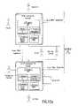
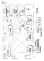
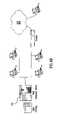
- FIG. 1is a schematic diagram of an automated vulnerability assessment tool comprising the VAT, the VAT Editor, and the TIMS, according to one embodiment of the present invention.
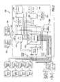
- FIG. 2is a block diagram of the architecture of the VAT of FIG. 1 .
- FIG. 3is a view of a screen from a graphical user interface of the VAT according to a preferred embodiment of the invention.
- FIG. 4is a symbolic diagram showing contents of the VAT database.
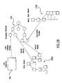
- FIG. 5is a diagram of a risk influence network according to a preferred embodiment of the invention.
- FIG. 6is a symbolic diagram showing inputs to the VAT database.
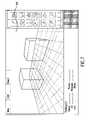
- FIG. 7is an exemplary illustration of a 3D builder screen.
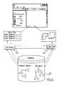
- FIG. 8is a view of screens generated by the GUI.
- FIG. 9is a symbolic view of the plug-in architecture.
- FIG. 10is a symbolic view of the report generation process.
- FIG. 11is a schematic view of the interaction of the VAT Editor with other system components.
- FIG. 12is a block diagram showing connection of the TIMS to remote computers/terminals.
- FIG. 13is a user/AVAT interconnection diagram.
- FIG. 14is a review of a Planner Interface screen format.
- FIG. 15is a review of the Risk Assessment Screen.
- FIG. 16is a review of the Risk Summary Table Screen.
- FIG. 17is a review of the “Probability of Attack” Screen.
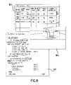
- FIG. 18is a review of the Risk Detail Screen.
- FIG. 19is a view of the 3D Viewer Screen.
- FIGS. 20 a–dare screen views illustrating the construction of a 3D object.
- FIG. 21is a block diagram of the Approach Vector Process.
- FIG. 22is a flow diagram of the Risk Management Process.
- FIG. 23is a data flow diagram of Blast and Fragment plug-in data flows.
- FIG. 24is a data flow diagram of Chemical/Biological/Radiological plug-in data flows.
- FIG. 25is a schematic diagram of a user created report format.
- FIG. 26is a block diagram of the VAT Data Model.
- FIG. 27is a block diagram of the Meta Data Model.
- FIG. 28is a symbolic diagram of Meta Data Model.
- FIG. 29is a block diagram of the VAT showing dependency relationships.
- FIG. 30is an object association diagram of the database.
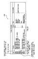
- FIG. 31is a table of exemplary screen definitions.
- FIG. 32is a process diagram of the navigational override process.
- FIG. 33is a block diagram of the risk management process.
- FIG. 34is a block diagram showing risk steps and influence network interaction.
- FIGS. 35 a and 35 bare susceptibility determination and risk mitigation process diagrams, respectively.
- FIG. 36is a diagram showing the relationship between the Influence Network, the graphical user interface, and calculations made against the model.
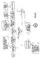
- FIG. 37is a flowchart showing calculation of approach vectors.
- FIG. 38is a block diagram of the Dynamics Module.
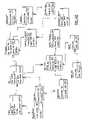
- FIG. 39is an object model to relational model conversion map.
- FIG. 40is a class diagram of the Relational Data Model.
- FIG. 41is a flowchart of the 3D Builder Process.
- FIG. 42is a flowchart of the 3D Viewer Process.
- FIG. 43is a block diagram of the 3D Run-time Environment.
- FIG. 44is a block diagram of the VAT Report Generator Subsystem.
- FIG. 45is a schematic diagram of the VAT Plug-in Interface Class Structure.
- FIG. 46is a VAT plug-in state diagram.
- FIG. 47is a review of the TIMS Browser screen.
- FIG. 48is a TIMS Client-Server network diagram.
- FIG. 49is a view of the VAT Editor Modes screens.
- FIG. 50is a view of a user interface screen.
- FIG. 51is a node—GUI relational diagram.
- FIG. 52is a package diagram of the VAT Editor.
- FIG. 53is a block diagram of the VAT Editor.
- the inventionhas many uses, it finds particular utility in the terrorism risk management arena. Thus, the invention will be discussed in connection with terrorism risk management embodiments. However, as will be discussed further below, the invention is useful in many fields and is not limited to terrorism risk management embodiments.
- an automated vulnerability assessment tool (AVAT) 100includes a vulnerability assessment tool (VAT) 200 , a theater information management system (TIMS) 130 , and a VAT Editor 150 .
- the toolmay be run on a personal computer or workstation.
- VATvulnerability assessment tool
- TIStheater information management system
- VAT Editor 150a VAT Editor
- the toolmay be run on a personal computer or workstation.
- the VAT 200presents a single interface to the user that accesses a powerful underlying architecture.
- This architectureshown in FIG. 2 , is a complex integration of modules that are collectively employed to meet the needs of the VAT 200 users.
- FIG. 2shows the modules that comprise the VAT 200 , the VAT's 200 external interfaces, and the relationships among the components. This complex architecture is better understood by a description of how the system is used.
- the GUI 202provides a web-like interface to the system with easy navigation references, screens that are simple and logically organized, and based on a dialog with the user rather than a form-based input.
- the VAT 200 User Interface exemplary screen 300 depicted in FIG. 3illustrates what the user interface looks like as the user enters information. This screen 300 allows direct access at all times to the tools associated with the VAT 200 and provides a structured or non-linear progression through the data entry interview, depending on user choice.
- the GUI Engine 210shown in FIG. 2 , (the term engine in a software context relates to a program that provides a specific capability, but is easily modifiable to support various implementations.
- a “GUI Engine”is simply a program to interact with the user graphically, without requiring scripted user interface screens.
- a Web browseris a good example of a GUI Engine 210 —the browser displays any Hypertext Markup Language (HTML) document and its links without them being programmed in the browser) allows user interface content to be different for each user while the structure of the interface 202 remains the same. This allows the VAT 200 to communicate differently with Planners and Professional Assessors, or even among the Services.
- HTMLHypertext Markup Language
- the Planner interface 204contains instruction, examples, and a more verbose dialog to elicit the same information that the Professional Assessor may be able to enter through a simple form provided by the Professional Assessor interface 206 .
- the GUI Engine 210receives all of the screens, questions, and display data through the Database module 220 .
- the Database module 220is a relational database that contains all of the data used by the VAT 200 , whether entered by the user, or calculated by the VAT 200 , as shown in FIG. 4 .
- Driving the GUI 202 from the Database module 220allows the user interface 202 to be dynamic, customizable, and readily updateable without reprogramming the user interface 202 .
- GUI's 202first task is to elicit data from the user through the interview process
- the primary objective of the GUI 202is to interface with the underlying Computational Engine 230 module, shown in FIG. 2 .
- the Computational Engine 230combines user-entered data, along with data stored in the Database module 220 , to calculate risk and all of its underlying components.
- the Computational Engine 230uses elaborate artificial intelligence and simulation algorithms to analyze and assess the specify targets, threats, vulnerabilities, and ultimately, the risks at a user's site.
- the foundation for the Computational Engine 230is the Influence Network 500 shown in FIG. 5 .
- This network 500shows all of the nodes 510 , 510 a that ultimately affect the risk of a given threat against a given target.
- the values for each of the nodes 510 , 510 aare combined using probability and statistics equations that account for the weighting of the various nodes and the uncertainty in their values.
- the network 500also provides results without requiring all of the data to be known. Thus, if the user does not have information for the detailed leaf nodes 510 a the network 500 can adapt and solve the network 500 based on higher level data.
- the VAT 200 architectureallows nodes 510 , 510 a and sub-nodes (not shown in FIG. 5 ) of the network 500 to be ‘turned-on’ as new information is available. With additional information, the confidence in the results should increase. For example, the likelihood of an attack may not change as the user adds additional information at the leaf nodes 510 a , but we can be more confident in the threat likelihood if it is backed up by supporting information. This flexibility allows users to gain quick insights into their risks and improve on their risk assessment as additional information is available.
- This network 500also provides a rigorous, quantitative calculation of risks.
- the network 500provides an intuitive representation of the factors that the calculation considers. It can be read as, ‘Leaf node X influences branch node Y, which, in turn, influences node Z’.
- the network 500is capable of handling influences that cannot be quantitatively described. Thus, if one cannot be sure how much the anniversary of the Branch Davidian incident will affect the Probability of Attack (via the “Triggers” Leaf Node 510 a ), one can still include it in the network 500 calculation by simply stating that it may increase the probability.
- the implementation of the network 500 in the Computational Engine 230also allows for the network 500 to be changed or modified without re-programming. Thus, if experts or events indicate that a new factor should be considered, it can be added to the risk network 500 by creating a new node object in the Database 220 .
- the network 500provides an integrated representation of the factors that impact the specific risks at a site in a manner that can be understood by subject matter experts (to validate the model) and interpreted by the VAT 200 so that results can be displayed in a meaningful manner to VAT 200 users.
- the data used by the network 500 , as well as the network 500 itself,can be modified and upgraded by modifying the database 220 without deriving a new equation or reprogramming the VAT 200 artificial intelligence (AI) algorithms.
- AIartificial intelligence
- the Computational Engine 230manages all of these calculations. When the calculation involves the physics-based interaction of objects (i.e., like driving a truck), the Dynamics module 240 (shown in FIG. 2 ) is used to calculate the forces, speed, acceleration, and other relevant physical parameters. When the calculation requires detailed modeling of weapons effects the Computational Engine 230 accesses external models through the Plug-in Interface 250 and uses the results of the model in the consequence nodes of the network 500 . Each network node is stored in the Database module 220 .
- the Computational Engine 230relies on a 3D representation of the user's site. This site is developed using the 3D Builder module 260 . Like the GUI Engine 210 , the 3D Builder module 260 is driven by the Database module 220 and all of the information entered into the 3D Builder 260 is stored in the Database module 220 . Thus, all of the interfaces in the software are tightly integrated with a single database, as shown in FIG. 6 .
- the 3D Builder 260provides an interface for the user to build a 3D representation of his site.
- the 3D Builder 260imports files from computer aided design (CAD) programs or images and uses them as the outline for the site layout.
- CADcomputer aided design
- the usercan then ‘build’ virtual representations of the buildings, roads, and perimeters of the site and identify population centers, VIPs, and countermeasures.
- This virtual representation of the siteis stored in the Database module 220 and is used by the Computational Engine 230 to compute threat vectors and the accessibility of assets and by the Analytic Models to calculate weapon effects against targets.
- the GUI 202must also display complex risk, spatial, temporal, cost, and probabilistic data to the user in a useful and effective manner. Because the terrorist threat is often so vague and multi-dimensional, the information display must present simplified representations of the information and allow the user to interact with the information to see how the data is inter-related—what kinds of assets are most susceptible to a certain threat, which threats bear the highest consequences, and so on. Information from the risk influence network 500 and information in the Database module 220 can be interpreted and displayed in many combinations and representations.
- the GUI 202provides sortable tables, text interpretations of data, 3D animations of scenarios, and graphs like the screens 801 , 802 , 803 shown in FIG. 8 .
- the GUI 202provides web-like capability to drill-down into any high level information presented by the GUI 202 . For example, if the probability of attack for a given threat is described in the GUI 202 as ‘high’, the user will be able to click on ‘high’ and drill-down to the nodes that caused the value to be high (e.g., Organization X is active in your area, they have Y weapon capabilities, and Z holy day is a trigger for this threat).
- the nodes that caused the value to be highe.g., Organization X is active in your area, they have Y weapon capabilities, and Z holy day is a trigger for this threat.
- the Computational Engine 230interprets threat data and recommends countermeasures to the user that should be used to reduce the threat or the consequences of an attack. These countermeasures are not limited to hardening of assets (blast walls, FRF, etc.) but include countermeasures to:
- the Database module 220retains the relationships among these countermeasures and procedures and the threats that they counter to allow the user to develop a defensive posture.
- the 3D Builder 260allows the user to specifically place countermeasures and optimize their placement to be most effective against the threat.
- the VAT 200allows the user to consider costs when employing countermeasures to manage risk.
- the VAT 200does not provide a detailed cost modeling or cost benefit analysis capability; however, for classes of countermeasures the user may select, the VAT Database 220 is populated with ‘initial cost’ and ‘recurring cost’ parameters. The values for these parameters are defined as none, low, moderate, or high.
- the databasealso contains fields for the user to enter dollar costs for specific countermeasures, if desired. These costs can be printed in custom reports or viewed in risk summary tables to sort and rank risk mitigation strategies by cost.
- the VAT 200uses existing blast and nuclear, chemical, biological, and radiological (NCBR) models to calculate the consequences used by the Computational Engine 230 .
- NCBRradiological
- the plug-in interface 250provides a mechanism 900 (shown symbolically in FIG. 9 ) to send the model data from the VAT 200 that is needed to properly execute the model.
- the results of the model calculationsare then sent back to the VAT 200 where they are interpreted and used by the risk network 500 and presented to the user. All of this happens without the user having to launch another program, learn how to use each of the external models, or enter the same information over again in another application.
- the VAT 200 architectureallows other developers to interface to the VAT 200 and provide new models and capabilities that were not initially built in to the VAT 200 .
- This flexible architectureensures that the VAT 200 is not limited to yesterday's state-of-the-art, but rather, that it can be upgraded through plug-ins to take advantage of evolving models and data.
- the data used by the decision network 500 , the GUI 202 screens, and the database 220 itselfcan be modified by the VAT 200 support organization.
- the VAT 200can be readily modified to use this new information.
- the VAT Database 220can be exported from the system. This will not only allow for back-ups of the data, but also allows the Database 220 to be exchanged among users. This will allow Professional Assessors to import an installation's existing VAT Database 220 and use that as the starting point for their assessment—thereby eliminating the need to re-enter data.
- the VAT 200will provide, at a minimum, the report formats from the JSIVA Report and the AT/FP Installation Planning Template. Information from the VAT 200 will be used to populate these reports and the user will be able to finish the reports by writing the remaining required text. This document will then be saved to the database and will be available in Microsoft WordTM format for reproduction.
- the VAT 200will also provide the flexibility for users to create custom reports or to save out and print VAT 200 risk assessment reports.
- the AVAT 100 Suite designprovides a flexible architecture of component modules and a suite of tools (referred to herein as the VAT Editor 150 ) that can be used to modify the system.
- These toolsallow the VAT 200 support organization to modify the VAT 200 without having to rely on the system developer or wade through millions of lines of code. Since all of the components of the system are tightly integrated with the Database module 220 , the VAT Editor 150 essentially provides a way to modify the existing database 220 to change the GUI 202 , Computational Engine 230 , report output, etc., a shown in FIG. 11 .
- TMSTheater Information Management System
- the VAT 200 informationis also available to Senior Commanders via the TIMS 130 to compare among the sites within their area of responsibility (AOR).
- the TIMS 130is a web-based application that allows Senior Commanders to view top-level threat, vulnerability, and risk data from multiple VAT databases 220 . These databases are stored in the TIMS 130 database that can be located on any web network 1200 . The Senior Commander will access this database through a web browser client on any connected computer 1210 as shown in FIG. 12 . Data from the TIMS 130 can be compared, sorted, searched, and graphed.
- the TIMS 130will be built using industry standard web technologies so that it can be integrated with other web applications.
- the VAT 200can also exchange data with other applications. This will allow the VAT 200 to import and export data to the JSIVA Information System (JIS) and other similar applications. This will ensure that users who have an investment in other applications will be able to effectively migrate to the VAT 200 and that users of all of the applications will be able to exchange data. While it may not be possible or desirable to provide an exchange mechanism for all of the data among the VAT 200 and other systems, the Plug-in Interface 250 will minimize the amount of re-entry of existing data.
- JISJSIVA Information System
- the VAT 200 , TIMS 130 , and the VAT Editor 150may be deployed for, by way of non-limiting example, the identified users as shown in FIG. 13 .
- FIG. 13shows the typical configurations for each user and the interfaces among the users.
- FIG. 3A preferred embodiment of a VAT 200 interface design is illustrated in FIG. 3 .
- This designprovides a web-like interface.
- the main content 310 windowdisplays the interview, calculated results, and the 3D scene to the user.
- the panel 320 to the left of the main content window 310provides an outline view for context and to allow the user to navigate the application as he/she desires.
- the toolbox 330 on the far left of the screen 300provides ready access to major components of the system including external analytic models, the simulation, and output reports.
- FIG. 14 and FIG. 15are examples of the types of screens that appear in the main content window.
- the typical Planner Interface Screen 1400as shown in FIG. 14 , has large fonts, natural English, and establishes context for questions and information before they are presented.
- the Risk Assessment Screen 1500is a notional representation of an intelligent natural language representation of risk data provided by the Computational Engine 230 .
- This screen 1500can be customized for each site or user, uses natural English, and interprets the risk network 500 data like an expert would.
- This interfaceallows the user to click on words like “High” to see the underlying information that influenced that determination.
- This screencan be printed or used in custom output reports.
- the Risk Summary Table 1600shown in FIG. 16 , provides a powerful mechanism for the user to interact with risk data and understand the risks to their site. Clicking on data within the table 1600 displays detailed supporting information. Selecting a row allows the user to see all of the details for that row or to view a simulation of the event represented by that row.
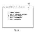
- the Risk Detail Screen 1800is accessed by clicking on the value of any of the calculations represented in the Risk Summary Table 1600 .
- the userclicked “High” in the “Prob of Attack” column of the 500 pound car bomb against the Headquarters row.
- This screenshows all of the detailed information for 500 pound car bombs.
- the usercan click on “more” for any of the statements that support the “High” assessment to see the information that they are based on.
- This datais derived from the Risk Influence Network 500 .
- the Risk Detail Screen 1800can also be accessed through the outline view.
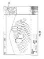
- the usercan then view scenarios in a 3D simulation/gaming environment in order to gain more insight into the threat vector as played against his/her site layout and countermeasure setup.
- the 3D Viewer 280allows the user of the VAT 200 to play various threat scenarios against his/her site.
- the site layoutis read in from the database as constructed in the 3D Builder 260 .
- the Computational Engine 230is then invoked to calculate threat vectors, and the resulting data displayed on top of the layout in a three-dimensional view.
- the useris then able to select a vector based on delivery type, risk value, or other such factors, and play the threat against the site in a realistic manner so that the consequences can be viewed.
- the usercan then switch to the 3D Builder 260 mode to add countermeasures, move countermeasures, or make other changes, and then run the simulations again as he/she builds up a site layout and plan.
- FIG. 19displays a simplified example of a 3D Viewer Screen 1900 .
- the 3D Builder 260allows the user to construct his base in the VAT 200 system for use with the various modules to calculate vulnerability and mitigate risk.
- the useris presented with a palette of standard 3D construction tools, camera movement options, and structure types to build.
- the countermeasure library and structure typesare read in from the database, and the list is presented to the user so he can select a structure to build, maintaining the notion of a dynamic interface to the user based upon the information in the Database module 220 .
- the userthen uses the tool to build up the site on top of a base image of the layout (scanned-in map, perhaps) or use a base AutoCAD DXF file if applicable, to add countermeasures, and to define the site perimeter.
- FIG. 7An exemplary interface to the 3D Builder module 260 of the VAT 200 is shown in FIG. 7 .
- the road networkcan be drawn in using line segments, and any bodies of water can be placed. If any structure requires additional information (such as number of people inside, etc.), the text area below the 3D view is used for text input that will be stored with the object.
- the usercan then place any existing countermeasures such as cameras, guard posts, or jersey barriers for each THREATCON level to set the site baselines. The site is then saved out into the database when all structures and countermeasures are placed.
- FIG. 20The process of building a structure is outlined in FIG. 20 .
- the userselects, point by point, the outline of the base of the structure (View 1 ).
- the systemthen fills in the outline and creates a solid 2D polygon (View 2 ).
- the useris then able to pull up on this polygon with motion of the mouse to extrude the shape into the third dimension up to the required height (number of stories or exact height) (View 3 ), and the system displays a final rendered building with shading and textures applied (View 4 ).
- Building other structuresfollows a similar method, with differences based on scale/orientation of the object. Smaller objects, or objects that cover large areas are “painted” in using an object brush.
- Jersey barriersfor example, are placed one at a time; each “paint spot” showing up as one barrier. Once placed, it can then be moved or rotated as desired.
- the Influence Network 500provides the VAT 200 with a knowledge base from which to determine risk.
- the network 500is comprised of all of the nodes 510 , 510 a that ultimately affect the risk of a given threat against a given target.
- a nodeis defined as a piece of data used to influence other data in the network 500 .
- the nodes 510 , 510 a in the network 500are combined to calculate belief. This belief is interpreted as the probability of a certain result occurring, based on all of the data available to make a determination. This determination can be made using either complete or partial data.
- the network 500can adapt to solve the problem based on the data entered.
- One of the more common techniques for representing probabilistic knowledge in a network 500involves Bayesian networks.
- the Influence Network 500is made up on a series of nodes 520 , 510 a with connections between each other.
- a nodecan have parents (nodes that cause an effect) and children (nodes that are affected), but the network 500 can not contain cycles (circular paths among nodes).
- Nodes without parentsare considered leaf nodes 510 a , and are typically where evidence is added to evaluate the network 500 .
- Each node 510 , 510 ais assigned a set of possible states, along with the probability of the state occurring. These probabilities reside in a structure called the conditional probability table, and represent the influences of prior beliefs on the decision.
- the conditional probability tablesimply contains probabilities of the node occurring. These values are set by the evidence assigned from external data.
- conditional probability tables of all nodes in the network 500are initialized to a default state, which is an expected bias in the answers. As evidence is posted to the network 500 , these probabilities are refined and the network 500 produces answers in which we have more confidence. In this manner, partial data can be used to refine beliefs, with the initial probabilities responsible for “filling in the gaps” of missing data. Using advanced statistical techniques, the confidence of each probability can also be computed. This confidence is extremely beneficial for justification of answers. Because of the subjective nature of various data used by the system, defense of the system's results is vital.
- the structure of the network 500is simple to represent. This presents flexibility in the VAT 200 design, allowing the network 500 to be configurable from the object database 220 .
- each node 510 , 510 a of the network 500is aware of its parents, children, and where it receives its data.
- the network 500 structurecan be stored in the database 220 and manipulated externally by the VAT Editor 150 .
- the usercan modify the behavior of the Influence Network 500 .
- Thisis extremely beneficial to the VAT 200 , as data refinement is vital to the survivability of the tool.
- decisions made by the network 500can be modified to produce answers that are more accurate.
- nodescan be added to the network 500 to refine beliefs. These nodes can only derive their data from the GUI 202 , but by adding the node to the network 500 and modifying the tables of all nodes that it affects, the network 500 behavior can be altered.
- Data used by the network 500comes from several different locations. Data entered by the user directly into the GUI 202 , as well as data resulting from the database and from calculations made by the Computational Engine 230 , the Dynamics module 240 , and external models are all used by the network 500 . By providing data from various sources, the decisions made by the influence network 500 are highly robust, dependent not only upon user knowledge, but also on statistics, simulation, and physics.
- the Computational Engine 230is responsible for constructing and maintaining the network 500 .
- User inputs to the GUI 202are posted directly to the network 500 , but the Computational Engine 230 coordinates any other input, resulting from calculations or external models.
- the vectors of approach that are calculated by the VAT 200determine the accessibility of a specific target to a specific threat (an actor with a weapon system). These vectors not only provide valuable data to the relative risk determination of the VAT 200 , but when displayed graphically they provide a powerful tool for the user in understanding the vulnerabilities to their site.
- a specific threat and targetIn order to compute the vectors of approach, a specific threat and target must be selected by the user. Using this data, the VAT 200 analyzes the threat and asset characteristics, the site layout, and the physical security measures to determine all possible approach vectors to the target.
- FIG. 21outlines the complete process for creating the approach vectors.
- the primary algorithmic techniques employed in creating these vectorsare: a weighted graph search algorithm, first-order physics, decision theory, and pattern recognition.
- the weighted-graph search algorithmsearches for a path between two points, avoiding obstacles and impassible areas.
- First-order physicsare applied to ensure realism in the chosen path.
- Decision theoryis applied to determine the reactions of the threat upon encountering countermeasures.
- Risk management supportis provided in the VAT 200 by allowing the user to modify the site baseline based on the determination of vulnerabilities to specific threats. Once the user builds the baseline, characterizes assets and determines specific threats, the VAT 200 walks him/her through a susceptibility determination and consequence analysis. Susceptibilities and consequences, coupled with the probability of a specific threat attack, make up the relative risk of a target against that threat. In order to perform risk management, the user must reduce the susceptibility of a target to an attack, the likely consequences of an attack, and/or the probability of the attack occurring. All of these can be reduced through the employment of countermeasures or asset relocation.
- FIG. 22provides an overview of the risk management process. Based on the current site baseline and the vulnerabilities determined by the VAT 200 , the user is presented with countermeasures to employ across their installation. By targeting the placement of these countermeasures against the specific vulnerabilities, the user can reduce risk. To assist in this process, the VAT 200 analyzes the threat and suggests countermeasures that can best reduce the components of risk associated with the threat. Comparing the effectiveness of the countermeasure against the threat accomplishes this. Countermeasures that are most effective against the threat are presented to the user, along with suggestions for successful employment. These countermeasures are not limited to hardening of assets (blast walls, Mylar on windows, etc.) but include countermeasures to:
- the site baselineis ultimately modified.
- the new baselineis then used to produce updated susceptibility and consequence determinations.
- Other risk management optionssuch as asset relocation will also be permitted. This cyclic process highlights the iterative nature of risk management and its application to planning.
- the VAT 200also allows the user to consider costs when managing risk. Preferred embodiments the VAT 200 do not provide a detailed cost modeling or cost benefit analysis capability; however, for classes of countermeasures the user may select, the VAT Database 220 is populated with ‘initial cost’ and ‘recurring cost’ parameters. The values for these parameters are defined as none, low, moderate, or high. The database also contains fields for the user to enter dollar costs for specific countermeasures, if desired. These costs can be printed in custom reports or viewed in risk summary tables to sort and rank risk mitigation strategies by cost.
- the VAT 200uses analytic models to calculate the consequences of likely threat scenarios.
- the Influence Network 500requires an assessment of the consequences of an event in order to calculate the overall risk.
- the VAT 200 potential consequencesare simply damage to assets and human casualties. From these results, the risk network 500 calculates additional parameters such as the mission impact and the symbolic victory the terrorist may receive based on biasing values the user has entered for the affected assets.
- the VAT 200 User Groupselected the models that will be provided with the initial release of the VAT 200 .
- the VAT Plug-in interface 250is also capable of interfacing with other models via the Analytic Models Interface. Table A below lists the models that are supported by preferred embodiments of the VAT 200 . Other models may also be supported.
- a design goalis to make the interaction of the VAT 200 with external models appear transparent to the end user.
- the VAT 200provides all of the set-up data required by the models in the correct format and interprets the damage and casualties calculated by the model.
- the data required from the user by the VAT 200may be simple, the interaction of the VAT 200 and external models is quite complex. This complexity is due to several important issues.
- the VAT 200is written to accept data from models that calculate consequences for all kinds of weapons systems.
- the VAT 200includes plug-in modules that allow interfacing to six models covering blast, chemical, biological, and radiological agent scenarios.
- third party developersmay produce plug-ins that interface with other kinds of models in the future. Therefore, the VAT 200 must consider other kinds of models in its use of analytic models.
- the sections belowdescribe the approach that the VAT 200 takes for each of the model interfaces present in preferred embodiments of the VAT 200 .
- the ensemble of blast and fragment consequence calculatorsis diverse principally in the target dimension, the weapons themselves for the purposes of VAT 200 being substantially described by their net explosive weight and the presence or absence of efficient provisions for fragments.
- Targets, on the other hand, and particularly buildingsvary enormously in their sizes, shapes, construction details, the care in which they were constructed, their age, and their outfitting.
- surrounding buildings and natural terrain featurescan markedly intensify or diminish blast and fragment effects on a given building and on its occupants.
- the presence of buildingscan shield people in the open from fragments, can channel weapon fragments at some people, and can contribute building fragments (especially but not exclusively glass fragments) to the injury-inducing or lethal objects flying through the air in the wake of an explosion.
- the CBR familyIn contrast to the blast and fragment family of weapon-target encounters, the CBR family is knit together by the dependence of all of them on wind-borne travel from release point to target. In the CBR family the variety is provided by the method of dispersal, meteorological/terrain effects, and by the varying quantities/qualities of the agents themselves.
- Blast and fragment analytic modelsmodel one or several physical phenomena. These include air blast, fragmentation, structural response, and casualty or personnel hazard mechanics. All of the blast and fragment analytic models preferred embodiments address building damage in some fashion or another. In order to function they need three categories of inputs or assumptions. These categories are the characteristics of the weapon, the characteristics of the building being analyzed, and the geometric and geographic context for the weapon and the building.
- a full real-world description of a weaponincludes its net explosive weight, its shape, its containment vessel, boosters such as the presence of bottles of acetylene, and additional fragment generators that came with the weapon.
- the weaponis concealed, as in the case of explosives concealed in an automobile or in the sides and bottom of a suitcase, the distribution of the explosives can affect the shape and power of the explosion.
- Buildingshave a host of features relevant to the calculation of damage.
- the detail with which the VAT 200 user characterizes buildingsmay not match the detail for a given analytic model.
- One optionis to group buildings into general classes (e.g. two-story, box-walled building). This general characterization could be provided to models equipped to expand that into a representative building.
- VAT 200could do the expansion and send the representative building details to an analytic model. For either alternative there will be a reduction of predictive accuracy relative to providing actual details.
- a contrasting case for building constructionis when the VAT 200 user provides greater detail than an analytic model is equipped to use.
- population within a buildingmay have multiple representations: the total population in the building, numbers of people in each bay of a building, or individuals' specific positions within the building.
- VAT 200expects the following output from blast and fragment models:
- FIG. 24illustrates the data flows for the chemical, biological and radiological (CBR) plug-in models.
- the atmosphereis the vehicle for dispersion of CBR agents after release. Atmospheric dilution, interaction with water or with other substances in the atmosphere, and in the case of biological pathogens, exposure to sunlight, all act to degrade the toxicity of one or another of these agents. CBR effects calculations require (in order of priority) agent release specifics, meteorological conditions, terrain, and time of day.
- CBR substance release informationincludes agent type, amount, mechanism for release, and delivery mechanisms.
- the release mechanismdescribes how and how well an agent is aerosolized (e.g., explosive charge, spray, etc.) while delivery mechanism is the means of introducing the weapon system to the target (e.g. letter bomb, aircraft, etc.).
- VAT 200needs casualties and “damage” resulting from CBR attacks. Damage is partly the result of casualties, especially casualties to key and essential personnel, but it can also be the result of denial of use of facilities or an area and equipment until decontamination has been performed.
- Casualty informationcan be provided several ways. One is simply a count of dead and incapacitated. An analytic model provides such numbers on the basis of that portion of supplied population databases which applies to the installation in question. A second method of expression is to provide geographically keyed data expressing the lethality density of the substance as a function of time. From the latter, VAT 200 is able to calculate its own casualty information taking into account building-by-building and area occupancy as a function of time of day. Even when the analytic model counts the casualties the geographic data is still useful for assessing secondary mission impact (i.e. “damage”).
- VAT 200do not model or use the details of the interior of buildings or related heating and ventilation systems so the effects on personnel inside of buildings from CBR releases will be approximated by a standard mitigation factor.
- standard procedures relevant to minimizing the casualties inside of buildings from CBR releasese.g. turn off air conditioning or ventilation system are provided.
- TSWG's Bomb Cardanalytically represented in VAT 200 , provides ranges for building evacuation and ranges for withdrawal of people in the open. Both are indexed on a progression of common or likely terrorist explosive devices, ranging from 5 pound pipe bombs to 60,000 pound semi-trailer trucks.
- the building evacuation distancesare purely a function of net explosive weight.
- the open air evacuation distancesare a composite of predicted effects from case shrapnel, thrown vehicle fragments, and glass breakage.
- VAT 200will supply only type of bomb and net explosive weight in TNT equivalent pounds to the Bomb Card model due to the simplicity of the Bomb Card “model” approach (i.e., a simple look-up table).
- the Bomb Carddoes not use any geometric and geographic information beyond the XY coordinates of the burst—for example height of detonation and presence of blast walls or nearby reflective natural or artificial features are not taken into account. Most importantly, no account whatever is taken of the character or construction of buildings.
- the Bomb Cardwill return information about building damage and potential for casualties to personnel in the open.
- AT Plannera product of the U.S. Army Engineer Waterways Experiment Station, was developed to aid engineers in evaluating Force Protection issues from terrorist and saboteur attack. In its native mode it is a GUI-based interactive tool.
- Featuresinclude the ability to make building retrofit recommendations and the ability to recommend barriers to stop vehicles of a specified size with a specified distance for acceleration.
- Three-dimensional views showing building damageare available in the GUI 202 version and it is possible to request standoff distance calculations for specified buildings, specified damage types such as roof/wall failure or glass breakage, and for weapons of a specified net explosive weight.
- AT Plannercan use precise positions of persons outside of buildings, detailed window distribution information, treats building occupants only by calculating injury potentials in the interior bay by bay, and can incorporate the mitigating effects of blast walls close to the point of detonation. Threats are specified in net explosive weight of the equivalent TNT charge. However, detonations inside of building are not modeled and AT Planner does not use height of burst or weapon fragmentation data, and its ability to represent irregularly shaped buildings is limited.
- AT Planner's productsinclude casualty information for outside individuals, coded panel-by-panel damage information for buildings, and a three-dimensional representation of building damage. VAT 200 will use these data to determine detailed consequences for threat-target pairs.
- Blast/FXTMwas developed by TRW Inc. (formerly BDM Inc.) for the Federal Aviation Administration as a tool to model the effects of explosives against buildings and the people in them. Additional features include the ability to predict severity of injury to individuals at precise locations inside the building. Buildings may be described in substantial engineering and architectural detail and fragment characteristics of weapons are also modeled.
- Weaponscan be described by energetic chemical and net explosive weight (describing one in terms of the TNT equivalent net explosive weight is sufficient). Fragmenting capability can be inferred from the casing but also fragment sizes can be specified, so that the model can accommodate weapons with bundled shrapnel such as nails.
- Blast/FXTMis alone among the VAT 200 analytic models in being able to take into account the specific locations of individuals within buildings.
- Extensive building construction detailcan also be used by Blast/FXTM: beams, columns, floors, and walls can be described for multiple levels by dimension, by category of material, and in the case of reinforced concrete, by the rebar spacing. Windows can be described by size and glazing material. Instead of requiring this level of construction detail from users, the VAT 200 will provide representative construction details corresponding to the generic building class selected by the user since preferred embodiments of the VAT 200 do not include the modeling of the interior of buildings.
- Blast/FXTM's products returned to VAT 200include the mortality or severity of injury to each person included in the scenario, component by component damage information, and three-dimensional views of the blast area with damage and casualties color coded (plus associated data to support this visualization).
- FP Toolis a product of the Naval Surface Warfare Center (NSWC), Dahlgren, Va. Unlike AT Planner and Blast/FXTM, FP Tool uses the TNT Standard methodology instead of the Kingery-Bulmash algorithms for its calculations. NSWC chose the TNT Standard in order to increase the accuracy of the calculations, especially for reflected air blast and elevated burst situations. Of the three blast and fragment models interoperable with preferred embodiments of the VAT 200 , only FP Tool takes height of burst into account. The FP Tool also precisely models air blast-pressure decay but even with FP Tool the prediction is apt to be conservative.
- Explosions internal to buildingsmay be modeled in the FP Tool. Exterior wall panel damage is predicted while interior walls are ignored in the calculation of this damage.
- the current releaseuses eardrum damage and fragment-skin penetration as metrics for air blast personnel casualty.
- the travel and consequences of fragments of the buildings themselvesare not modeled in the current release of FP Tool: only casing fragments are considered. Fragment trajectories are calculated both for bursts outside and for bursts inside of buildings. When a fragment reaches an impediment, penetration is calculated on the basis of the fragment and the construction of the impediment. casualties to people from fragments are calculated on the basis of probability of hit for personnel in hazard volumes rather than on the basis of precise positions of occupants.
- FP Toolalso calculates probabilities of equipment destruction from fragments.
- the FP Toolcan use weapon size, three-dimensional burst position information; multiple buildings; and barrier information. Building generic type, percentage of glass, and population density are usable but more extensive construction details are not. Equipment type and fragility can be used, if provided.
- Results passed from FP Tool to VAT 200include air blast information, building collapse information, building fragment information, building damage information, equipment casualty information, and personnel casualty information.
- the CBR Cardprovides a quick look assessment for casualties related to the use of CBR agent releases.
- the purpose of this applicationis to provide a range of probable consequences from typical CBR attacks.
- the Cardprovides actual “Lethal Dosage 50” (L/D 50 ) values for a given release.
- L/D 50is the dose for which 50% of the affected population is likely to die from the given exposure.
- the casualtieswill take place over a variable time frame depending on the agent: chemical agents act very quickly (within minutes to hours) while biological and radiological may take days to weeks to kill. However, the dosage calculation will be determined assuming that the personnel in the area remain there for 30 minutes after the release.
- the CBR Cardis meant to provide a rough estimate of the consequence from a CBR attack and also to provide insight into crucial aspects of CBR releases. While the Bomb Card focused on standoff as the primary countermeasure to blast, the CBR Card will show the relative importance of time and situational awareness as critical weapons against CBR agent releases. Time is critical since if personnel can don a gas mask immediately upon being notified of a release then the hazard from CB releases is fairly minimal. Similarly, for radiological agents, limiting time exposed to the agent is the only way to prevent casualties for unprotected personnel.
- the CBR Cardpermits several chemical agents to be selected: chlorine, VX, and GB. These three were selected because they span the likely threats in four relevant dimensions: availability, persistence, lethality, and history of use.
- Chlorineis a representative industrial chemical agent meeting the test of easy availability. It is a toxic industrial material that has been discussed as a terrorist threat for years. It is lethal, its dense gas characteristics enable a cloud to linger in the absence of wind, and it is readily available. Moreover large tanker trucks are not uncommon, so inconspicuous delivery is plausible. Because of its likely packaging as a tanker truck the likely scenario is for a large amount of chlorine (tens of thousands of kilograms) to be released by a small explosive rupturing the tanker near the target.
- VXis included in the CBR card to represent the persistent chemical agents
- GB Sarinis included to represent the agents of highest lethality.
- the two conditions of midnight release and noontime releasewere selected to show the disparity between the dispersion and the degradation of CBR releases under differing meteorological conditions.
- Midnight releasemeans no turbulence and no wind.
- the resulting transport and dispersionoccurs because of a physical phenomena called meander which is the random fluctuation of wind azimuth coupled with random variations of a small wind speed. (That is to say, it really is not physically possible to have absolute calm conditions.) Meander creates a slow moving erratic cloud that may eventually cover a large area.
- the noontime release conditionsprovide a turbulent atmosphere with a four-knot wind. This condition provides a situation where the initial release will quickly produce a fairly directional plume of ground effects. The wind speed of four knots was selected to provide a reasonable ground footprint over minutes to hours without diluting the release too quickly.
- Anthraxis sufficient to represent biological warfare agents.
- Anthraxis a worst case choice because as a spore it is relatively resistant to ultraviolet light so it has a long linger time (relative to other biological agents) and is also more lethal than most other biological agents. It is also readily available and, unlike the chemical agents, it can kill at a long distance from its point of release. Three different, plausible delivery mechanisms are used—aircraft spray, van spray, and backpack spray.
- Cobalt 60is a likely source due to its availability from medical applications.
- One delivery methodis used (suitcase bomb) for its application since in any other form it would be very dangerous to the terrorist employing it and an explosive release provides an effective way to spread a small amount of material quickly.
- the two parameters that the CBR Card will require from the userwill be direction of prevailing wind and location of the source.
- the data produced from the series of CBR scenarios described abovewill be applied to the site within VAT 200 with these two pieces of data. In this way, personnel affected by the release may be calculated and provided as a consequence term and, if requested by the user, plotted on the site map.
- the prevailing wind conditionis very important for CB releases since it specifically identifies the region at risk from a CB release.
- the usermay experiment using different wind azimuths to determine the severity of a CBR attack during non-nominal meteorological conditions (i.e., the user may perform what-if analyses).
- the CBR Carddoes not consider terrain effects. All scenario runs assume flat terrain. This simplification could obviously be important especially for very hilly terrain and urban areas.
- HPACHazard Prediction and Assessment Capability
- HPACcan either determine typical meteorological conditions for the site's geographic location and season of the year from its own resident databases or a default file will be made available for modification. In addition, the terrain will affect the transport and dispersion but VAT 200 assumes flat terrain. Data from HPAC will be typical contours showing the extent of a cloud's growth scaled to dose levels representative of physical impairment and/or high probability of death.
- HPACis capable of using every bit of the agent cloud, time and meteorology, and geographic data that VAT 200 will supply. Some users of VAT 200 will be unable to provide information in detail and so will instead characterize weapons, weather, and geography by generic category. Together, VAT 200 and HPAC will extrapolate from these to the details HPAC's computation engine requires in order to run.
- HPACdoes not directly calculate casualty information.
- VAT 200will receive geographic lethality and incapacitation information from HPAC that it will then use both for casualty and for mission impact assessment.
- the VAT 200provides a mechanism that allows end users to enhance the functionality provided by the VAT 200 on delivery.
- the VAT Plug-in module interfaceallows third parties to create software modules that extend the VAT 200 's capabilities beyond those delivered as part of the standard VAT 200 installation.
- plug-in modulesThere are currently three variants of plug-in modules: Analytic Model plug-ins, Data Analysis plug-in modules, and I/O plug-in modules.
- Analytic Model plug-insData Analysis plug-in modules
- I/O plug-in modulesI/O plug-in modules. The following sections discuss the VAT 200 's Plug-in module interface and the capabilities of each of the plug-in types in an overview fashion that attempts to provide context for the other sections of this specification.
- the VAT 200 's external interface mechanismis constructed around the notion of software plug-in modules which provide enhanced behavior for the VAT 200 in specific areas of functionality: new analytic models, new textual data interpretation paragraphs, or new sources to import or export data to or from the VAT 200 .
- Software plug-in modulesare binary objects built from compiled code that adheres to standards defined for the AVAT 100 Suite.
- the VAT 200expects a base level of functionality that manages the low-level interface with the VAT 200 software. On top of that functionality, the VAT 200 expects that a plug-in will implement additional functionality that will allow the plug-in to provide enhanced behavior for the VAT 200 software.
- the overarching design principle for the Plug-in module interface designis to make it easy for third party programmers to develop plug-ins for different situations, not precluding the possibility that more than one plug-in of a particular type (e.g. two analytic model plug-ins and/or three analysis module plug-ins) may be registered with the VAT 200 and potentially be running concurrently with the others.
- a particular typee.g. two analytic model plug-ins and/or three analysis module plug-ins
- the VAT 200 Analytic Models Interfacewill allow module developers to create interfaces to external analytic models and interface them with the VAT 200 . Through the Analytic Models Interface the VAT 200 will be capable of exporting munitions, terrain, geometry and other information in the VAT Database 220 for analytic models to use in their calculations.
- VAT 200 Analytic Models Interfaceprovides a number of control functions that allow the VAT 200 to control the execution of a compliant Analytic Model.
- the VAT 200After execution, the VAT 200 expects to receive results from the model.
- the kinds of information that an Analytic Model can return to the VAT 200are listed below.
- Consequence to LifeThe effect on the human population in the area surrounding the event. This value is used in the influence network 500 to affect the overall risk value.
- Consequence to AssetsThe effect on the assets affected by the event. This value is used in the influence network 500 to affect the overall risk value.
- 2D, 3D, and 4D(3D + Data values returned to the VAT 200 that allow time) data objects the VAT 200 to visualize the results of a model execution.
- Data Annotations Itemsused to annotate the visualization of data returned from an analytic model.
- the VAT 200In support of the user created report format requirement, the VAT 200 exposes the Data Analysis modules interface.
- the VAT 200uses Data Analysis modules to interpret the results of user-entered data and formulate statements about that data. Throughout the interview process for Professional Assessors and Planners and during the creation of output reports, the VAT 200 uses Data Analysis modules to create custom paragraphs of text.
- the exposed interfaceallows end users to create their own Data Analysis modules that can be used in user modified screen sets or in user defined output report formats.
- the Data Analysis module interfaceincludes control methods that allow the VAT 200 to interact with Data Analysis modules and exposes portions of the VAT Database 220 to allow the module to perform queries on the database.
- the third external interface the VAT 200 exposesis the IO module interface.
- the VAT 200uses IO modules to read and write data from/to external data sources.
- the VAT 200includes IO modules for importing data in the following formats:
- the VAT 200may also include an IO module for the following format:
- the VAT 200has a report generation capability that assists in the preparation of JSIVA formatted professional assessment reports, assessment team briefings, and AT/FP plans.
- the VAT 200allows the user to define additional report formats that can be used to generate new report types in addition to those originally supplied with the VAT 200 .
- the VAT 200accomplishes this by storing report formats that define the information to be contained in VAT 200 generated reports in a content independent format. Report formats are editable from within the VAT 200 Editor. Using the report format editor, the user can modify any of the report formats supplied with the VAT 200 and/or create completely new formats that are unlike those supplied with the VAT 200 .
- Report formatsare the heart of the VAT 200 's report generation capability.
- the VAT 200stores report formats that represent all the report types that the VAT 200 produces. Even the AT/FP Plans and Professional Assessment Reports that the VAT 200 generates are created using VAT 200 report formats. Report formats define for the VAT 200 the contents of a report independently of the information that will ultimately be contained in the reports. Using a report format, at report generation time the VAT 200 iterates through user entered site information and assembles a report based on the information.
- Report formatsconsist of a small set of elements that can be assembled by the VAT 200 in building block fashion to create a whole document. As shown in FIG. 25 , report formats consist of Sections 2510 , Paragraphs 2520 , and Clauses 2530 . Major divisions of generated documentation are stored as sections in VAT 200 report formats. Sections consist of a title element and one or more paragraphs that make up the body of the block. Each section in a VAT 200 report format contains paragraphs that define the content of the block. Paragraphs in VAT 200 reports are usually what their name implies—paragraphs of text—although the VAT 200 extends this definition slightly for added flexibility by allowing graphs and tables to be inserted as paragraphs 2520 . As with sections 2510 , paragraphs 2520 may contain clauses 2530 that define the content of the paragraph 2520 . Clauses 2530 are the lowest level element of a VAT 200 report format.
- Paragraphs in a VAT 200 report formatmay be one of several different types.
- the simplest form of paragraphis a boilerplate paragraph that contains text that is constant for all reports generated using the report format. Boilerplate paragraphs insert their exact contents into generated reports.
- Another, slightly more complex type of paragraphis the analytic paragraph. Analytic paragraphs are created from the output of a Data Analysis module plug-in (see the external interfaces section for more information on Data Analysis modules). Using Data Analysis modules and analytic paragraphs, end users can create completely new forms of output for VAT 200 reports.
- the next most complex form of paragraphis a composed paragraph.
- Composed paragraphsare paragraphs that have one or more clauses that are used to build the body of the paragraph at generation time. Composed paragraphs insert the contents of the clauses that comprise them into generated reports.
- clausescan take multiple forms.
- the simplest form of clauseis a boilerplate clause.
- boilerplate clausesare copied into generated reports unchanged.
- the second form of a clauseis the query clause.
- Query clausesrepresent simple database queries. At report generation time, the query is conducted and its results are what is inserted into generated reports.
- the VAT 200 softwareaccepts and stores a multitude of data elements including user input data, analytic model results and influence network 500 evaluation results.
- data elementsincluding user input data, analytic model results and influence network 500 evaluation results.
- the VAT 200 uses to organize informationIn order to provide structure to that data and make it available to all of the parts of the VAT 200 system that may need it, there are three models the VAT 200 uses to organize information.
- the Influence Network 500has been specifically discussed previously due its central influence on the VAT 200 's complex risk calculations.
- the VAT 200maintains a Data Model, which contains information about the physical elements of a particular domain, and the Meta Data model. This section describes each of these models, their relationship to the other models, and how the VAT 200 uses them to develop a complete representation of a site.
- the VAT 200 Data Model 2600shown in simplified form in FIG. 26 , is how the VAT 200 organizes information about the real-world elements that can exist in the site under analysis.
- the association of physical items, agents, and events as the association element called AT/FP Domainforms the base of the diagram.
- Each of the branches of the treerepresents an orthogonal view of the world that represents items from the most general to the most specific.
- physical itemsare real objects in the world that occupy space. For example under this organization, one could say they have a physical object, which is a vehicle, which is a land vehicle, etc. proceeding from the most general to the most specific.
- Agentsrepresent entities in the world that have intent and perform actions. An example agent would be the U.S. Army or a terrorist organization.
- eventsare triggers that are likely to bring about change in the world state or cause an agent to act. An example would be a coup or the occurrence of a religious holiday.
- the VAT 200 's second use of the Data Model 2600is to use instances of elements of the Data Model 2600 as part of associations that are part of the VAT 200 's Meta Data Model (shown in FIG. 27 and described below). These element instances represent items that actually exist as part of the profiles that the VAT 200 is being used to create.
- the VAT 200 's Meta Data Model 2700shown in FIG. 27 , is the VAT 200 's central aggregation mechanism for data about sites that the VAT 200 profiles.
- the VAT Meta Data Model 2700stores information about the collections of elements from the Data Model 2600 that are useful in the AT/FP domain.
- the structure of the Meta Data Model 2700is primarily based on associations since it focuses on bringing together objects into real world constructs.
- Sites 2730are composed of a Site Layout 2731 and one or more Information Products 2732 , Threats 2733 and Site Baselines 2724 .
- the VAT 200uses the Site Layout 2731 to store all of the static information about a site's infrastructure, structures, and natural environment.
- Site Baselines 2724are used to store data about the dynamic elements of a site such as employed countermeasures, asset locations, and organizations as these elements are organized for a particular configuration (e.g. one may speak of the THREATCON Alpha baseline versus the THREATCON Bravo baseline.)
- the Influence Network 500provides a central framework from which the VAT 200 evaluates risk.
- Each of the nodes 510 , 510 a in this network 500represents an element that affects the overall risk for a given threat against a given target.
- Nodes in the network 500can have parents (nodes that cause an effect on this node) and children (nodes that are affected by this node), but the network 500 cannot contain cycles.
- an influence algorithmdescribed fully in the Influence Network 500 section
- each of the nodes in the network 500takes a set of possible states, each with a probability of occurring.
- the values at children nodesare influenced by the values in parent nodes in the network 500 .
- the VAT 200populates the leaf nodes 510 a of the Influence Network 500 using a combination of directly entered data, data pulled directly from the Data or Meta Data models 2600 , 2720 , and calculated information based on data gained from network 500 searches.
- data entered into the Data Model 2600 and the Meta Data Model 2700directly or indirectly affect the site specific Influence Network 500 and therefore affect the site's overall risk profile.
- the VAT 200is divided internally into nine subsystems that each implement a part of one of the data models, the influence model, the user interface, or other systems that operate on the models to perform useful calculations.
- the subsystemsare identified in the next section and defined in detail in later sections.
- the VAT 200is internally divided into nine subsystems. Each of these subsystems is implemented as a separate software package with a public interface that the other subsystems use to interact with the package.
- the VAT 200 Package Diagram 2900 in FIG. 29shows the VAT 200 , its subsystems, and their dependency relationships.
- the block symbolse.g. GUI Engine 210
- the dotted arrowsshow which of the VAT 200 's subsystems depend on others. For each of these dependencies, the lower level package (at the arrowhead end of the arrows) will implement an internal system interface.
- this diagramshows the external interfaces that have been defined for the VAT 200 . These interfaces are discussed in the section above entitled External Interfaces.
- the VAT 200uses a GUI Engine 210 .
- the GUI Engine 210reads and creates the user interface from the database 220 at run-time. This approach provides a GUI 202 that can be modified by changing the database 220 instead of the code. It also provides the ability to define different user interfaces for each type of user. This allows the interfaces to be customized to fit the user's specific needs and level of understanding.
- the current user interface concepthas five main sections menu bar, navigation bar, tool interface, outline view, and dynamic content area. Each of these sections are created and managed by the GUI Engine 210 .
- the menu barprovides file input/output commands, edit functions, simple navigation, and access to help.
- the GUI Engine 210passes the commands to the appropriate VAT 200 subsystems and interacts with the Windows clipboard as requested by the user.
- the navigation barprovides the user with web like navigation (back and forward buttons) and quick access to important features and sections of data in the VAT 200 .
- the GUI Engine 210stores a screen history that it uses to determine what screen to display when the back and forward buttons are used. They act exactly like the buttons found on a web browser. The remaining buttons on the navigation bar are linked to specific screens in the VAT 200 that are immediately displayed when the user presses them.
- the tool interfaceprovides direct access to various tools contained in the VAT 200 .
- Each of the buttonswhen pressed, instructs the GUI Engine 210 to activate a specific VAT 200 tool and display its interface.
- the outline view's two purposesare to represent the data in the system and to allow the user to move around in the VAT 200 to view, edit, and change data.
- the GUI Engine 210populates the outline as data is entered into the system and as the VAT 200 needs information from the user. The information is displayed in an outline form to better organize and manage its representation.
- the most important part of the interfaceis the dynamic content area. This portion of the interface contains the screens that:
- the GUI Engine 210reads information from the database and creates screens to allow the user to interact with the system. This area, like the rest of the interface, is completely controlled by the GUI Engine 210 , but the 3D Engine 210 is also capable of writing information to it. Whenever the 3D Builder 260 or Viewer 280 is needed, the GUI Engine 210 provides a graphics context to the 3D Engine 210 so that it can display graphics in the dynamic content area. The GUI Engine 210 creates and manages all the toolbars that are required to operate the 3D Builder 260 and Viewer 280 . It passes the commands issued by the user to the 3D subsystem for processing. This provides a consistent interface to the user and relieves the 3D sub-system from the duties of handling user input.
- the GUT Engine 210handles multiple screen definition sets so that each one can be customized to fit a specific set of users, but it does not require that every screen be customized. Instead the engine supports default screens in addition to user type specific screens. This provides a mechanism where the GUI Engine 210 uses a default screen anytime a user type specific one does not exist. This makes the engine 210 more flexible and defining custom screens less time consuming.
- Each object in the system that requires user interactionhas a least one screen associated with it. This is the default screen to be used by the GUI Engine 210 . In addition to that screen each object can have other screens associated with it to be used by a specific type VAT 200 user as shown in FIG. 30 .
- GUI Engine 210uses screen definitions to define what the dynamic content area of the user interface should contain. These definitions define what the screen should contain, but not explicitly how it should be displayed or laid out. This has two main advantages:
- the user interfaceis more flexible.
- the screen definitionssuch as the definition 3100 shown in FIG. 31 , consist of a list of what should be shown on the screen, but not how it should be laid out. This approach frees modification users from the duties of having to graphically lay out each screen so that they can better concentrate on the content of the screen. It also allows the GUI Engine 210 to be more flexible by allowing it to adapt the screen to the size and style of the window available. It furthermore allows the engine to decide, based on the type of data to be input to output, what is the best way to display it.
- the GUI Engine 210uses the screen definition 3100 to determine what to display on the screen. To determine how to display the information it checks the type of data and determines what input or output device to use. For example, if the definition 3100 specified that the user's name should be entered, the GUI Engine 210 would check the database and know that this is a string. It would then use a text-input box on the screen for the user to type the information into. If on the other hand the definition 3100 specified that the users rank be entered (and a list of acceptable ranks exist), the engine would use a selection box so that the user would not need to type in the answer. This technique is applied to all of the items in the list until the entire screen composition is known.
- GUI Engine 210uses rules similar to a web browser to layout the information on the screen. It determines the spacing between lines, knows to emphasize the title of the screen, etc. Once this process is finished, the engine displays the screen to the user and handles all the interactions.
- the GUI Engine 210is also responsible for determining what screen to show when. The user can jump to specific screens by using the navigation bar, outline, and tool bar, but this is only part of the navigational process. During the interview for example, the user will press a done or next button to indicate that they are ready to proceed to the next screen. The GUI Engine 210 is responsible for finding it.
- the engine uses during navigationThere are three methods that the engine uses during navigation. The first is to jump to a user-specified screen as described above. The second is to look at data dependencies in the object model and influence network 500 . Many of these objects require information about other objects. The GUI Engine 210 uses this information to determine what object screen the user should see next. But, this method alone may not produce a coherent progression of screens.
- the GUI Engine 210is equipped with one final navigational method.
- a screen definitioncan also specify other screens to be displayed. This allows it to override the default behavior of the system in order to provide a directed screen progression.
- a sample diagram of this processis shown in FIG. 32 .
- the Computational Engine 230 subsystem of the VAT 200is responsible for providing support to the risk determination and mitigation processes. During these processes, the Computational Engine 230 builds and maintains the structure of the influence network 500 , in addition to performing calculations to support decision-making.
- FIG. 33illustrates the many steps of risk determination and analysis with which the Computational Engine 230 is involved.
- the key to the knowledge of the VAT 200lies in the Influence Network 500 .
- This network 500embodies the factors that the VAT 200 relies upon in making decisions during risk determination and mitigation.
- Risk determinationis composed of four major components: criticality determination, threat determination, susceptibility determination, and consequence analysis.
- Risk mitigationis comprised of countermeasure effectiveness analysis and consequence analysis.
- Each of these distinct componentsinteracts with the influence network 500 in order to make decisions, and each decision made affects the rest of the Influence Network 500 .
- the Influence Network 500is capable of calculating the relative risk of a particular target against a particular threat.
- FIG. 34illustrates the interaction between these steps of the risk process and the Influence Network 500 .
- the susceptibility determination and risk mitigation componentsIn addition to interacting with the primary VAT 200 Influence Network 500 , the susceptibility determination and risk mitigation components also make use of local networks in order to make complex decisions, as shown in FIGS. 35 a , b.
- threat intentions and capabilitiesare compared to countermeasure effectiveness to determine the reaction of the threat upon encountering a countermeasure. This complex inference is handled using a miniature Influence Network.
- risk mitigationalso uses threat and countermeasure characteristics in making decisions.
- Various countermeasuresare compared to the specific threat to determine which ones are most effective at mitigating the risk of the threat against the target. These local decisions do not directly derive from the prime Influence Network, so they are handled independently.
- the structure of this networkis used to control the progression of the screens shown to the user, and the data collected by the network 500 determines the resulting output.
- the networkis capable of propagating data through itself in order to make decisions, but it must rely on external means to obtain this data.
- the GUI 202provides a portion of this data directly from the user through elements on the screen. The remaining data is the result of various calculations performed by the Computational Engine 230 .
- FIG. 36depicts the relationships between the nodes of the influence network, the data connection with the GUI 202 , and the calculations made against the data model.
- the primary calculation that the Computational Engine 230 is responsible foris the generation of approach vectors. These vectors represent the many ways in which a threat can reach the target in order to attack. Based on these vectors, the accessibility of the target is calculated and used in the influence network 500 to determine relative risk. FIG. 37 outlines the steps necessary to construct these vectors.
- Step 1 – 37involves computing the range from the target that the threat must reach in order to affect consequences.
- Step 2 – 37which is in reality the controlling loop of the process, involves using a weighted graph search technique to build the path. This technique takes two points and builds a path between them. In building the path, the algorithm seeks to minimize cost, which in this case is the number of countermeasures that it must face, and maximize effectiveness, or the resulting consequences to the target.
- Steps 3 – 37 and 4 – 37are actually responsible for supporting the weighted graph search algorithm.
- Step 3 – 37involves the actual reasoning component that deals with countermeasures.
- the search algorithmcan evaluate the response of the threat to the countermeasure(s), and if necessary, can alter the path based on the results.
- Step 4 – 37involves the application of first-order physics to the threat delivery mechanism.
- the weighted graph algorithmdetermines the types of terrain that the delivery mechanism can cross, and the areas that the mechanism can fit through.
- the local influence network 500makes use of physics to determine the denial capabilities of the countermeasure(s) against the threat.
- the Dynamics module 240calculates the speed and timing of the threat along the path, for use in later playback.
- Step 5 – 37 of constructing vectorsconsists of refining the many paths that are produced. Invariably, similar and redundant vectors are generated, differing only slightly from other vectors and not providing useful data to the process. Using pattern-matching algorithms, these extraneous vectors are removed in order to simplify the final representations. Finally, in step 6 – 37 , the accessibility value of the threat to the target is calculated for each vector. Once all of the interesting vectors have been constructed, the accessibility of the site is computed based on the accessibility values of all vectors. This value is used directly by the influence network 500 to determine relative risk.
- the Dynamics module 240is responsible for calculating and updating the state of the physical objects during the simulation of the threat ingress, given realistic physical properties of the environment and objects acting in the environment.
- the Dynamics module 240is the set of code that modifies and stores the state vectors of all objects.
- a state vectoris a set of physical characteristics and measurements that describe completely the current configuration of a given object.
- the state vector used in the VAT 200includes position in three-space, a rotation quaternion to describe the rotation of the object, the linear momentum, and the angular momentum. This state vector is then updated every computation cycle of the Dynamics module 240 as external forces interact with the object and impose a change on the state vector configuration.
- the Dynamics module 240has three main sections. The first represents the object itself. The others act on that object and are labeled as the Force Accumulator and the Equation Solver. For each cycle of the computation the object sends a message to the Force Accumulator module to sum up all forces acting upon the object.
- the Force Accumulatorhas knowledge on how to calculate the various forces in accordance with the Lagrangian dynamics equations (dynamics equations based on energy conservation). For example, the Accumulator will access other objects if there is a collision force, or access only the gravitational constant if it is the gravitational force desired. The total force vector is then passed back to the object.
- FIG. 38shows a complete module diagram and data flow outline.
- the Solveruses an implicit method of solving the ordinary differential equation and utilizes dynamic time steps to minimize errors that occur in stiff Ordinary Differential Equations (ODE) (those that can “blow up” during standard explicit computational methods with too large a time-step).
- ODEOrdinary Differential Equations
- the Dynamics module 240is able to simulate any simple physical phenomena, such as object—object collisions, gravitational acceleration of an object, friction and resistance effects, and deformation events.
- the physical object as stored in the Dynamics module 240has a volume (spatial extent), mass, and a state vector as described above.
- the VAT 200In order to store the many sources of data used throughout the system, the VAT 200 employs a relational database. With a relational database, the VAT 200 is capable of saving data from previous sessions for the user to access later. In addition, the database provides a framework for sharing data between modules in the system, and between users at different locations. FIG. 4 summarizes the many different types of data stored in the VAT Database 220 .
- the VAT Database 220 operationmust be totally transparent to the typical user. This is because the architectural requirements will not support the traditional model where a database administrator manages the database independent of the application.
- the VAT 200 systemis unique in the sense that it must operate in both standalone and traditional multi-tier modes. Therefore, the VAT Database 220 is designed in such a way as to provide data storage capabilities that are transparent to the user and require zero maintenance.
- VAT 200 architectureis predominantly object-oriented in nature.
- a relational databaseis not object-oriented, but is organized by tables.
- the codeis commonly referred to as a ‘mapping’ code because it is used to map the application objects to relational entities in the database.
- mapping codeis commonly referred to as a ‘mapping’ code because it is used to map the application objects to relational entities in the database.
- the goal of the VAT 200is to minimize the mapping code effort, while maintaining complete functionality with vendor independence.
- FIG. 39depicts the object-to-entity relationship.
- the VAT 200 applicationincorporates a database broker to perform the necessary object-to-relational mapping functions.
- the brokeris a distinct module in the VAT 200 application performing mapping functions, therefore encapsulating database access code. This approach provides a transparent conversion of the relational model into the VAT 200 's object model. Modifications to the relational model only require modification to the broker.
- the database brokerhandles all data storage and retrieval functions for the VAT 200 application, therefore housing the necessary database communication code. Regardless of the selected database, the interface between the VAT 200 application and broker remains constant.
- the relational data modelis implemented by defining relational entities for the VAT 200 object classes as shown in FIG. 40 . Each entity is designed to support the object model as efficiently as possible. The methods and aggregation features of the object model become incorporated into the database broker.
- the relational data modelbegins as a logical model defining the necessary entities and appropriate relationships between.
- the VAT 200contains the capability to render a site layout in a three-dimensional manner. This includes two modes of operation. The first is a 3D view that allows the user to construct a site or add objects to a site (3D Builder 260 ). The second allows the user to view a simulation run in a 3D environment (3D Viewer 280 ).
- the Builder 260 and Viewer 280are two modes of operation built on top of the 3D Run-time environment 270 , which is based on the OpenGL graphics library. Both use the same underlying rendering techniques, while presenting to the user different functionality. This allows the code base to be shared between the Builder 260 and the Viewer 280 , resulting in a smaller memory footprint, easier transition between Builder 260 and Viewer 280 portions of the VAT 200 , and a consistent 3D interface.
- the 3D Builder 260allows the user to construct his base in the VAT 200 system for use with the various modules to calculate vulnerability and mitigate risk.
- the useris presented with a palette of standard 3D construction tools, camera movement options, and structure types to build.
- the countermeasure library and structure typesare then read in from the database, and the list presented to the user in an appropriate menu so he can select a structure to build.
- the userthen uses the tool to build up his site on top of a base image of the layout (scanned-in map, perhaps) or use a base AutoCAD DXF file if applicable.
- a flow diagram of the builder processis shown in FIG. 41 .
- the Viewer 280allows the user to view the site layout as constructed in the Builder 260 , then displays the results of the computational cycle that calculates risk to various assets on the layout. This information is displayed as treat vectors” on the layout, or representations of paths that a threat delivery mechanism would take. Each of these paths can be selected by the user, and the threat scenario can then be played out, including the consequence display at the end based upon data received from the external blast or CB models.
- a flow diagram of the Viewer 280 processis shown in FIG. 42 .
- the 3D Viewer 280 and 3D Builder 260both sit on top of the base 3D Run-time engine as outlined in the previous section. Each interacts with different sub-modules of the Run-time to alter the user interaction, rendering mode, and display options.
- the Viewer 280while interacting with the Computational Engine 230 and Dynamics module 240 , communicates with the non-physical data structures to populate the threat vector display list. It also interacts with the camera model to change the view upon user request, as well as makes calls to the rendering engine itself to change display modes (switch to wire-frame mode, map textures differently, et cetera).
- the Builder 260needs to access the structure of static data to populate the terrain and structure information (static polygons), while also communicating with the rendering engine and the camera model.
- the Builder 260upon initial startup, takes input from a 2D image or a 2D AutoCAD file (DXF). This is then used as the base of the modeling session, which allows the user to build on top of the actual site layout in order to bring it into the third dimension.
- the DXF fileis parsed and translated into an internal format, and all 3D information generated by the Builder 260 is kept in an internal format for maximum efficiency.
- the modelis then saved out into a common 3D file format that can be stored into the data store (object persistence mechanism), and pulled up later in the Viewer 280 . All asset characteristic information is imbedded into the 3D-file format so that all information is in one location.
- Both the 3D Viewer 280 and the 3D Builder 260are based upon the same 3D Run-time Environment 270 (also referred to herein as the 3D simulation/gaming environment) that handles the rendering of the scene.
- the 3D enginestores texture information, polygonal models, and lighting information needed to render the scene quickly and realistically.
- a detailed look at the sub-modules of the 3D-Run-time Environment 270is found in FIG. 43 .
- the 3D Enginetakes input from the database to retrieve the site layout as built by the Builder, or from the current polygon structure that the user has constructed in the case of the Builder.
- the texture imagesare stored and linked from individual polygons, and the geometry of the layout and buildings are stored separately from the geometry of the mobile objects such as trucks.
- the polygons for static datasuch as the terrain and buildings are stored in a manner that is geared toward quick rendering, while the objects that move do not necessarily remain in the same physical area during the simulation, and so cannot take advantage of the spatially-ordered data structure.
- a Binary Space Partitioning (BSP) treeis then used to store the terrain and structure polygons to allow for the quickest rendering of a large scene while allowing for rapid view-frustum culling and level of detail control.
- BSPBinary Space Partitioning
- BSP treesallow all polygons to be stored in a tree structure that is branched based upon spatial position, so polygons close to one another in physical space are close in data space as well. These techniques are used to allow for faster rendering speeds on the limited hardware of the PC platform.
- the models used to draw all auxiliary vehicles and structuresare kept in a model library within the 3D-rendering module to facilitate the addition of new models.
- the truck modelsfor example, will not be stored integrated in with the site layout, but will be stored separately to allow addition or changes to the truck model.
- the site terrain and additional geometryare exportable to a common model interchange format (DXF) for viewing in an external model viewer independent of the VAT 200 .
- DXFcommon model interchange format
- the rendering engineuses the OpenGL graphics Application Programming Interface, or API.
- This library of graphics routineshas become the industry standard for fast real-time graphics, and is supported by most video hardware to provide acceleration and keep most of the graphics pipeline processing tasks off of the CPU.
- OpenGLprovides a robust set of primitive calls to render polygons with realistic lighting, shading, and texturing effects, z-buffering, and other advanced graphics features.
- the graphics librarylends itself to a scene graph approach for storing polygons and transforms internally, while also allowing for a BSP tree or other spatial structure to exist internally since OpenGL does not deal with higher-level polygon sorting or organization.
- a scene graphis a technique used to store rotations and translations in a tree structure. This structure allows changes at a higher level to affect all objects below the node; organizing rotations and translations in an efficient manner.
- the Report Generator module of the VAT 200is responsible for the creation of electronic and printed output from the VAT 200 system.
- the report generatoris driven based on inputs from the user interface that indicate the report type to generate and the desired output format.
- the report generatoralways operates on the active dataset for the VAT 200 .
- the Report Generator moduleis built around the design concepts expressed in the User Defined Report Generation Capability section. As described in that section, report formats form the heart of the report generation capability whose structure is reflected in its class hierarchy as shown in FIG. 25 , Report Format and FIG. 44 , VAT Report Generator module. In addition to the Report Format, Section, Paragraph and Clause object classes discussed in the User Defined Report Generation Capability section; the Report Generator module adds a class for the report that forms the public interface for creating reports in multiple formats, a report generator class that forms the public interface for the subsystem, and several subclasses which implement the specific behaviors for paragraph types, clause types, and output formats.
- the report generator objectdefines the public interface for the Report Generator module. It is the only object in this subsystem that persists throughout a VAT 200 execution. Other objects in the subsystem are instantiated and destroyed as necessary when generating reports or creating user-defined report formats.
- the report objectis an abstract object that is never instantiated. Instead, it defines the public interface to several subclasses that deal with the specifics of particular output formats. This indirect approach allows the VAT 200 to be more easily expanded in the future to include support for additional output file format types. Initially, the VAT 200 will be capable of creating documents in RTF, and Microsoft Word 97 TM formats.
- the GUI 202When the user requests to generate a report, the GUI 202 sends the report format, the desired output type, and optionally, an output file name.
- Report generationoccurs in two stages: qualification and creation.
- qualification stagethe report generation subsystem performs a walkthrough of the report format and verifies that each Section, paragraph, and clause has enough information to create its output. If qualification succeeds, then the subsystem actually creates the report.
- the subsystemIf qualification fails, then the subsystem returns with a failed qualification message. Reports that fail qualification may still be generated, however, some information may be indicated as being missing or incomplete. During generation of a report for which the format qualification failed, those sections, paragraphs, or clauses that failed will insert a qualification failure message in the output report that indicates that the required source data was not available.
- the VAT Plug-in Interface 250exposes portions of VAT 200 functionality to allow end users to enhance the capabilities of the VAT 200 beyond those that are delivered with the VAT 200 .
- the VAT Plug-in Interface 250 subsystemexposes four interfaces which collectively allow the user to enhance VAT 200 behavior in three areas: adding additional analytic models, adding additional textual interpreters, and adding additional data input and output converters.
- plug-insare self-registering Microsoft COM objects that implement the VAT Plug-in Interface and at least one of the other VAT Plug-in Interfaces 250 .
- the static structure of the VAT Plug-in interface 250 subsystemis shown in The Plug-In Interface Class Structure as shown in FIG. 45 .
- the plug-in interfaceis structured to support the four exposed interfaces; each external interface is represented internally by a class that provides the methods to interact across the interface.
- a higher level class plug-in interfaceimplements control for the plug-in interface and provides the public interface for the VAT Plug-in Interface module 250 .
- the VAT 200initializes the VAT Plug-in Interface module 250 , which then proceeds to register all plug-ins that are located in the VAT 200 system plug-ins directory and those in the user plug-ins directory. Each registered plug-in is then started by the VAT 200 to allow it to perform any resource allocation and startup processing that may be required. After VAT 200 processing has completed, this process is reversed. Each plug-in is shutdown to allow it to free any resources it may have acquired during the VAT 200 execution, and the VAT plug-in interface 250 is shutdown.
- Run-time processingvaries depending on the type of plug-in. As shown in FIG. 46 , while the VAT 200 is running the plug-in is dormant. When the user requests an analytic model execution, however, the plug-in proceeds through three states. The pre-execute state allows a plug-in module to perform any data gather/reformatting required for an impending model execution. After completing pre-execution processing, the VAT 200 proceeds through the execute state wherein the VAT 200 would actually execute the external model, and the post execute state where the VAT 200 allows the analytic module plug-in to perform any post processing and data collection.
- the TIMS 130is composed of seven screens:
- the login screenallows the user entry into the system based on a login ID and a password.
- a splash screenwelcomes the user to the system and offers a list of possible menu selections.
- the browse screen 4700is shown in FIG. 12 .
- the browse screen 4700gives the user the ability to sort the site entries based on several different methods.
- the usercan also search the sites for particular information using the search screen. Once the user had decided upon a particular site and report, the summary screen outlines all of the information available from that site.
- the compare screenthe user can perform side-by-side comparisons of different report entries, either from the same site or from different sites. At any time, the user can capture comments or memos for later use with the notes screen.
- the TIMS 130provides the user the capability to view individual VAT 200 sessions from multiple sites.
- the TIMS 130also allows the user to sort, search and browse the data from the individual VAT 200 sessions by categories such as threat type, risk, score and others.
- FIG. 12is an overview of user interaction with the TIMS 130 .
- Results from local VAT 200 sessionsare transferred to the TIMS 130 , in the form of the VAT Database 220 , and stored in a database along with sessions from other sites.
- the TIMS 130 usercan then analyze these various sessions using several browse and search techniques. Each session is viewable by selecting the Summary option, which displays a brief overview of the session's report and the information collected during the session presented in the form of charts and tables. At any point, the user can access a notes screen to capture comments for later review.
- the TIMS 130 database architectureis similar to the local VAT 200 with minor enhancements in order to support the TIMS 130 operational requirements.
- the TIMS 130is implemented on a high performance database server supporting multiple clients.
- the TIMS 130 databaseis designed to support the storage and access of multiple VAT 200 sessions from multiple sites. Each session is individually identified within the database supporting the TIMS 130 operational requirements.
- the Database Management System(DBMS) handles data concurrency, integrity and user authentication of the TIMS 130 sessions.
- the usercan perform many tasks to understand the information collected from the local sites, including:
- the TIMS 130 serverhandles the reception and storage of the local VAT 200 sessions, capturing each separate VAT Database 220 into one comprehensive data store. The user then accesses the collection of VAT 200 data by pointing their Web browser to the TIMS 130 server. The server also handles login and password authentication before allowing VAT 200 data to be viewed.
- the AVAT 100 Suiteincludes an editor that is capable of modifying the VAT 200 user interface, database, and reports formats.
- the editoris a standalone application that interfaces with the VAT Database 220 in order to make all of the available modifications. This is possible because the user interface definitions and report formats for the VAT 200 are all stored in the database instead of being compiled into the VAT 200 executable.
- the VAT Editor 150is capable of creating and editing the user interface screens and can define screens that are tailored to different types of users. It can edit the database to add object instances into the data model and modify the influence network 500 . Finally, the VAT Editor 150 can create, edit, and delete report formats to create new and customized reports to meet future needs.
- the VAT Editor 150will allow the user to both view and change many aspects of the VAT 200 application. It is designed to allow a knowledgeable user to customize and extend the VAT 200 to address future user needs.
- the toolwill have a mode for viewing and modifying the VAT 200 user interface, database, and output report formats. Each mode displays an overall picture of the item being edited and provides a toolbar on the left to issue edit commands. A mockup of the interface is shown in FIG. 11 .
- the User Interface Editing modepresents the user with a representation of the current screen flow in the system. It then allows the user to modify the flow of the screens, the content of the screens, and the look and feel of the application. Because the flow and contents of the screens are highly dependent on the contents and structure of the database, the Database 220 mode is always available to the user for reference.
- the Database Editing modeprovides the user with the ability to view and move around the database and its contents. It is capable of showing both the data model and the influence network 500 . From there the user can select a class or node to view and/or modify.
- the Report Format Editing modeallows the user to view the format of the reports in the VAT 200 . They can then create new reports from scratch, create new reports from existing report formats, and edit existing report formats.
- the VAT Editor 150will display the sections, paragraphs, and clauses that comprise the report format. The user can then select items to edit and/or insert new items from a list.
- the screen listing the three editing modesis shown in FIG. 49 .
- Nodes in the influence network 500 and the objects in the data model 2600drive the dynamic content of the user interface, shown above.
- Each of these itemshas one or more GUI 202 definitions associated with it as shown in FIG. 51 .
- Each GUI 202 definitionis also associated with a specific user type that will use it. The user is able to:
- the GUI 202 definitionscompletely describe the dynamic content for the given object. Using the VAT Editor 150 the user is able to specify.
- the VAT Editor 150can also specify the look and feel of the application. This applies to both the dynamic content and the static content.
- the usercan specify:
- the database-editing modewill allow the user to update and modify the database 220 to:
- the VAT Editor 150is not able to edit or add classes in the Data Model 2600 in preferred embodiments.
- Report formats in the VAT 200consist of sections, which can consist of paragraphs that can consist of clauses. The user is able to add, remove, or modify any part of a report.
- the VAT Editor 150allows the user to create modify, and delete the available sections, paragraphs, and clauses in the system.
- the usercan edit both the content and the formatting of the items in the report.
- the paragraphs and clausesare where all the report content is created. Sections, which can contain only paragraphs, are used to conveniently group paragraphs together for later reuse.
- FIG. 52illustrates the various components of the Editor 150 .
- the VAT Editor 150reuses packages of the VAT 200 .
- FIG. 53illustrates the various subsystems of the VAT Editor 150 .
- the modificationis aided by the plug-in architecture of the invention.
- riskprobability*vulnerability.
- Vulnerabilityis based on both susceptability and consequence.
- the structure of the influence networklends itself to modification for any of the above-referenced risk situations.
- the inventioncalculates susceptibility based in part upon the 3D simulation/gaming environment (referred to above as accessability calculations) and in part upon consequence calculations performed by existing external programs via the plug-in interfaces. Modification of this embodiment for an application such as home security is straightforward. For example, the consequence calculations, instead of being performed with blast and CBR models, can be simplified to calculate property loss and damage as a result of a burglary.
- the 3D simulation/gaming environmentcan be modified to calculate vectors representing probable burglar entry routes rather than weapons delivery routes.
- the inventionmay be modified for risk management of information theft by replacing the 3D simulation/gaming environment with a network security model.
- the 3D simulation/gaming environment(which calculates accessibility) can be replaced with a model that calculates the proximity of the spacecraft to space debris, and the blast/CBR calculators can be replaced with similar programs that model damage to the spacecraft resulting from collisions with space debris.
Landscapes
- Business, Economics & Management (AREA)
- Engineering & Computer Science (AREA)
- Accounting & Taxation (AREA)
- Theoretical Computer Science (AREA)
- Strategic Management (AREA)
- Finance (AREA)
- General Physics & Mathematics (AREA)
- General Business, Economics & Management (AREA)
- Physics & Mathematics (AREA)
- Marketing (AREA)
- Tourism & Hospitality (AREA)
- Development Economics (AREA)
- Economics (AREA)
- Primary Health Care (AREA)
- Health & Medical Sciences (AREA)
- Human Resources & Organizations (AREA)
- General Health & Medical Sciences (AREA)
- Educational Administration (AREA)
- Technology Law (AREA)
- Management, Administration, Business Operations System, And Electronic Commerce (AREA)
- Computer Security & Cryptography (AREA)
Abstract
Description
- AT Planner from U.S. Army Corps of Engineers Waterways Experiment Station
- FP Tool from Naval Surface Warfare Center, Dahlgren, Va.
- Blast/FX™ from TRW, Inc.
- Blast Card (Look-up table) from TSWG
- HPAC from Defense Threat Reduction Agency (DTRA)
- CBR Card (Look-up table) from Titan Corporation
| TABLE A |
| Analytic Models |
| Analytic Models |
| Model | Sources |
| AT Planner | U.S. Army Engineers Waterways |
| Experiment Station | |
| FP Tool | Naval Surface Warfare Center, Dahlgren, |
| Virginia | |
| Blast/FX ™ | TRW, Incorporation |
| Blast Card (Look-up Table) | TSWG |
| HPAC | DTRA |
| CBR Card (Look-up Table) | Titan Corporation |
- The
VAT 200 and each of the analytic models represent the same features in different ways requiring complex data transformations. - The analytic models have limiting assumptions that the
VAT 200 must track and present to users. - The
VAT 200 must ultimately accept data from the analytic models. TheVAT 200 software has no means to validate this data.
- The
- Structural damage;
- Casualty information; and
- Information keyed to the geography showing the extent of the various effects of the explosion.
Conceptual Data Flow betweenVAT 200 and CBR Analytic Models
| TABLE B |
| Analytic Model Information Table |
| Value | Description |
| Consequence to Life | The effect on the human population in the area |
| surrounding the event. This value is used in the | |
| value. | |
| Consequence to Assets | The effect on the assets affected by the event. |
| This value is used in the | |
| affect the overall risk value. | |
| 2D, 3D, and 4D (3D + | Data values returned to the |
| time) data objects | the |
| execution. | |
| Data Annotations | Items used to annotate the visualization of data |
| returned from an analytic model. | |
Data Analysis Module Interface
| TIFF - Image format | JPEG - Image format | ||
| DXF - Image format | BMP - Image format | ||
- Browsing data—The user can scroll through all of the information sessions collected from the local sites
- Searching—The user can search for particular sets of data based on specific information, such as a site or a date
- Ranking and sorting—The user can sort the data and assign rankings based on categories such as threat type, risk score, remediation cost, target types, and vulnerabilities.
- Comparison—The user can compare report sessions between the Professional Assessor and Planner, across different dates, and through other means.
- Create and edit user types
- Create and edit the
GUI 202 definitions that theGUI Engine 210 associates with each user type for each node and data model object.
- The title for the screen
- Screen breaks
- Static text
- Data input and output fields including:
- Associated prompts and questions
- Where the data is stored in the database
- How it should be entered including:
- Size limits
- Type limitations
- Choice lists
- Default values
- Images
- Placement
- Source file
- Buttons including:
- Text label
- Type
- Action
- The objects in the database that should be filled in next
- What type of
GUI 202 component is used for each type of data. Example: Boolean values are displayed using check boxes or a list box with true and false choices. - The format for specific types of objects on the screen. Example: Titles are bolded and centered.
- What type of
- The colors to use for
GUI 202 elements - The fonts to use for
GUI 202 elements - The images to use for icons
Database Editing
- The colors to use for
- Create and edit objects in the
Data Model 2600 by defining instances of existing classes. Example: Create a Jeep from the vehicle class by filling in its parameters. - Add simple nodes to the Node Tree that can only receive input from the user interface, they cannot access data model objects or system calculations.
- Adjust the influence of certain nodes in the Node Tree including any that they create.
- Add general data to the database for use in the
GUI 202 and reports.
- Create and edit objects in the
Claims (9)
Priority Applications (1)
| Application Number | Priority Date | Filing Date | Title |
|---|---|---|---|
| US09/853,691US7130779B2 (en) | 1999-12-03 | 2001-05-14 | Method and apparatus for risk management |
Applications Claiming Priority (2)
| Application Number | Priority Date | Filing Date | Title |
|---|---|---|---|
| US09/453,509US7231327B1 (en) | 1999-12-03 | 1999-12-03 | Method and apparatus for risk management |
| US09/853,691US7130779B2 (en) | 1999-12-03 | 2001-05-14 | Method and apparatus for risk management |
Related Parent Applications (1)
| Application Number | Title | Priority Date | Filing Date |
|---|---|---|---|
| US09/453,509DivisionUS7231327B1 (en) | 1999-12-03 | 1999-12-03 | Method and apparatus for risk management |
Publications (2)
| Publication Number | Publication Date |
|---|---|
| US20010027389A1 US20010027389A1 (en) | 2001-10-04 |
| US7130779B2true US7130779B2 (en) | 2006-10-31 |
Family
ID=23800833
Family Applications (4)
| Application Number | Title | Priority Date | Filing Date |
|---|---|---|---|
| US09/453,509Expired - LifetimeUS7231327B1 (en) | 1999-12-03 | 1999-12-03 | Method and apparatus for risk management |
| US09/853,691Expired - LifetimeUS7130779B2 (en) | 1999-12-03 | 2001-05-14 | Method and apparatus for risk management |
| US09/853,690Expired - LifetimeUS7308388B2 (en) | 1999-12-03 | 2001-05-14 | Method and apparatus for risk management |
| US11/931,545Expired - Fee RelatedUS9292874B2 (en) | 1999-12-03 | 2007-10-31 | Method and apparatus for risk management |
Family Applications Before (1)
| Application Number | Title | Priority Date | Filing Date |
|---|---|---|---|
| US09/453,509Expired - LifetimeUS7231327B1 (en) | 1999-12-03 | 1999-12-03 | Method and apparatus for risk management |
Family Applications After (2)
| Application Number | Title | Priority Date | Filing Date |
|---|---|---|---|
| US09/853,690Expired - LifetimeUS7308388B2 (en) | 1999-12-03 | 2001-05-14 | Method and apparatus for risk management |
| US11/931,545Expired - Fee RelatedUS9292874B2 (en) | 1999-12-03 | 2007-10-31 | Method and apparatus for risk management |
Country Status (3)
| Country | Link |
|---|---|
| US (4) | US7231327B1 (en) |
| AU (1) | AU1941401A (en) |
| WO (1) | WO2001040984A1 (en) |
Cited By (66)
| Publication number | Priority date | Publication date | Assignee | Title |
|---|---|---|---|---|
| US20030125997A1 (en)* | 2001-12-20 | 2003-07-03 | Allison Stoltz | System and method for risk assessment |
| US20030154150A1 (en)* | 2002-02-13 | 2003-08-14 | Marcus Wefers | Methods and systems for risk evaluation |
| US20030182337A1 (en)* | 2002-02-13 | 2003-09-25 | Marcus Wefers | Methods and systems for risk evaluation |
| US20030187699A1 (en)* | 2001-12-31 | 2003-10-02 | Bonissone Piero Patrone | System for rule-based insurance underwriting suitable for use by an automated system |
| US20040193563A1 (en)* | 2003-03-28 | 2004-09-30 | Hans-Ove Hagelin | Method of establishing rules for a device which is intended to be able to be used for generating decision support |
| US20050144114A1 (en)* | 2000-09-30 | 2005-06-30 | Ruggieri Thomas P. | System and method for providing global information on risks and related hedging strategies |
| US20050154617A1 (en)* | 2000-09-30 | 2005-07-14 | Tom Ruggieri | System and method for providing global information on risks and related hedging strategies |
| US20050165767A1 (en)* | 2000-07-20 | 2005-07-28 | Microsoft Corporation | Method and apparatus for identifying programming object attributes |
| US20060004594A1 (en)* | 2000-02-14 | 2006-01-05 | Overture Services, Inc. | System and method to determine the validity of an interaction on a network |
| US20060026044A1 (en)* | 2004-07-28 | 2006-02-02 | Smith Donald X Ii | Electronic content insurance system |
| US20060149790A1 (en)* | 2004-12-30 | 2006-07-06 | Gert Rusch | Synchronization method for an object oriented information system (IS) model |
| US20060167924A1 (en)* | 2005-01-24 | 2006-07-27 | Microsoft Corporation | Diagrammatic access and arrangement of data |
| US20060178860A1 (en)* | 2004-11-12 | 2006-08-10 | Glass Thomas G Iii | Crowd behavior modeling method and system |
| US20070203759A1 (en)* | 2006-02-27 | 2007-08-30 | Guy Carpenter & Company | Portfolio management system with gradient display features |
| US20070288208A1 (en)* | 2004-08-20 | 2007-12-13 | Lockheed Martin Corporation | Measurable enterprise CBRNE protection |
| US20080052054A1 (en)* | 1999-12-03 | 2008-02-28 | Anthony Beverina | Method and apparatus for risk management |
| US20080126108A1 (en)* | 2005-10-11 | 2008-05-29 | Hodgin C Reed | System and method for implementing a meteorological network for improved atmospheric modeling |
| US7383239B2 (en) | 2003-04-30 | 2008-06-03 | Genworth Financial, Inc. | System and process for a fusion classification for insurance underwriting suitable for use by an automated system |
| US20080133190A1 (en)* | 2006-02-13 | 2008-06-05 | Shay Peretz | method and a system for planning a security array of sensor units |
| WO2008076984A1 (en)* | 2006-12-16 | 2008-06-26 | Armando Alvarez | Methods and systems for risk management |
| US20080208637A1 (en)* | 2007-01-03 | 2008-08-28 | American International Group, Inc. | Method And System For Assessing Environmental Risk Associated With Parcel Of Real Property |
| US20080243439A1 (en)* | 2007-03-28 | 2008-10-02 | Runkle Paul R | Sensor exploration and management through adaptive sensing framework |
| US20080243425A1 (en)* | 2007-03-28 | 2008-10-02 | Eliazar Austin I D | Tracking target objects through occlusions |
| US20080275756A1 (en)* | 2006-12-07 | 2008-11-06 | Fujitsu Limited | Apparatus and method for analyzing business continuity, and computer product |
| US20090076991A1 (en)* | 2007-09-19 | 2009-03-19 | Torres Robert J | Method and apparatus for visualization of data availability and risk |
| US20090094007A1 (en)* | 2007-10-04 | 2009-04-09 | Hiroyuki Konno | System for defining simulation model |
| US7567914B2 (en) | 2003-04-30 | 2009-07-28 | Genworth Financial, Inc. | System and process for dominance classification for insurance underwriting suitable for use by an automated system |
| US20090248753A1 (en)* | 2008-01-03 | 2009-10-01 | Microsoft Corporation | Database management system risk assessment |
| US20090248488A1 (en)* | 2008-03-27 | 2009-10-01 | British Telecommunications Public Limited Company | Risk assessment forecasting in a supply chain |
| US7630910B2 (en) | 2001-12-31 | 2009-12-08 | Genworth Financial, Inc. | System for case-based insurance underwriting suitable for use by an automated system |
| US7698159B2 (en) | 2004-02-13 | 2010-04-13 | Genworth Financial Inc. | Systems and methods for performing data collection |
| US20100204969A1 (en)* | 2007-09-19 | 2010-08-12 | United Technologies Corporation | System and method for threat propagation estimation |
| US20100235274A1 (en)* | 2006-03-03 | 2010-09-16 | Yu-Chiuan Chen | Anti-terror platform for securing a community against terrorisms |
| US7801748B2 (en) | 2003-04-30 | 2010-09-21 | Genworth Financial, Inc. | System and process for detecting outliers for insurance underwriting suitable for use by an automated system |
| US7813945B2 (en) | 2003-04-30 | 2010-10-12 | Genworth Financial, Inc. | System and process for multivariate adaptive regression splines classification for insurance underwriting suitable for use by an automated system |
| US7818186B2 (en) | 2001-12-31 | 2010-10-19 | Genworth Financial, Inc. | System for determining a confidence factor for insurance underwriting suitable for use by an automated system |
| US20100293519A1 (en)* | 2009-05-12 | 2010-11-18 | Microsoft Corporation | Architectural Data Metrics Overlay |
| US7844477B2 (en) | 2001-12-31 | 2010-11-30 | Genworth Financial, Inc. | Process for rule-based insurance underwriting suitable for use by an automated system |
| US7844476B2 (en) | 2001-12-31 | 2010-11-30 | Genworth Financial, Inc. | Process for case-based insurance underwriting suitable for use by an automated system |
| US7895062B2 (en) | 2001-12-31 | 2011-02-22 | Genworth Financial, Inc. | System for optimization of insurance underwriting suitable for use by an automated system |
| US7899688B2 (en) | 2001-12-31 | 2011-03-01 | Genworth Financial, Inc. | Process for optimization of insurance underwriting suitable for use by an automated system |
| US20110131023A1 (en)* | 2004-05-29 | 2011-06-02 | Cambridge Systems Associates Limited | Computer Systems for Data Manipulation and Related Methods |
| US20110178949A1 (en)* | 2010-01-20 | 2011-07-21 | International Business Machines Corporation | Method and system enabling dynamic composition of heterogenous risk models |
| US20110191722A1 (en)* | 2010-02-04 | 2011-08-04 | Gill George M | Nested controls in a user interface |
| US20110196593A1 (en)* | 2010-02-11 | 2011-08-11 | General Electric Company | System and method for monitoring a gas turbine |
| US8005693B2 (en) | 2001-12-31 | 2011-08-23 | Genworth Financial, Inc. | Process for determining a confidence factor for insurance underwriting suitable for use by an automated system |
| US20120209645A1 (en)* | 2009-10-07 | 2012-08-16 | Wincor Nixdorf International Gmbh | System and method for providing data relating to business events within business processes |
| US20130332474A1 (en)* | 2012-06-12 | 2013-12-12 | Risk Management Solutions, Inc. | Predicting and managing impacts from catastrophic events |
| US20140278818A1 (en)* | 2013-03-15 | 2014-09-18 | Bmc Software, Inc. | Business development configuration |
| WO2010019461A3 (en)* | 2008-08-15 | 2016-01-28 | Raytheon Company | Method and apparatus for critical infrastructure protection |
| US20160232467A1 (en)* | 2015-02-10 | 2016-08-11 | Wipro Limited | System and method for optimizing the risk during software production release |
| US9607155B2 (en) | 2010-10-29 | 2017-03-28 | Hewlett Packard Enterprise Development Lp | Method and system for analyzing an environment |
| US9799208B2 (en) | 2014-10-27 | 2017-10-24 | Honeywell International Inc. | Physical and logical threat analysis in access control systems using BIM |
| US10148489B2 (en) | 2015-09-01 | 2018-12-04 | At&T Intellectual Property I, L.P. | Service impact event analyzer for cloud SDN service assurance |
| US10230326B2 (en) | 2015-03-24 | 2019-03-12 | Carrier Corporation | System and method for energy harvesting system planning and performance |
| US10361919B2 (en) | 2015-11-09 | 2019-07-23 | At&T Intellectual Property I, L.P. | Self-healing and dynamic optimization of VM server cluster management in multi-cloud platform |
| US10459593B2 (en) | 2015-03-24 | 2019-10-29 | Carrier Corporation | Systems and methods for providing a graphical user interface indicating intruder threat levels for a building |
| US20200035109A1 (en)* | 2018-07-24 | 2020-01-30 | Honeywell International Inc. | Custom search queries for flight data |
| US10606963B2 (en) | 2015-03-24 | 2020-03-31 | Carrier Corporation | System and method for capturing and analyzing multidimensional building information |
| US10621527B2 (en) | 2015-03-24 | 2020-04-14 | Carrier Corporation | Integrated system for sales, installation, and maintenance of building systems |
| US10756830B2 (en) | 2015-03-24 | 2020-08-25 | Carrier Corporation | System and method for determining RF sensor performance relative to a floor plan |
| US10928785B2 (en) | 2015-03-24 | 2021-02-23 | Carrier Corporation | Floor plan coverage based auto pairing and parameter setting |
| US10944837B2 (en) | 2015-03-24 | 2021-03-09 | Carrier Corporation | Floor-plan based learning and registration of distributed devices |
| US11036897B2 (en) | 2015-03-24 | 2021-06-15 | Carrier Corporation | Floor plan based planning of building systems |
| US11501234B2 (en)* | 2011-10-14 | 2022-11-15 | Albeado, Inc. | Pervasive, domain and situational-aware, adaptive, automated, and coordinated big data analysis, contextual learning and predictive control of business and operational risks and security |
| WO2024110494A1 (en) | 2022-11-21 | 2024-05-30 | Swiss Reinsurance Company Ltd. | Open digital, data driven underwriting (uw) system and loss event simulation platform and method thereof |
Families Citing this family (298)
| Publication number | Priority date | Publication date | Assignee | Title |
|---|---|---|---|---|
| US7809642B1 (en) | 1998-06-22 | 2010-10-05 | Jpmorgan Chase Bank, N.A. | Debit purchasing of stored value card for use by and/or delivery to others |
| US6615189B1 (en) | 1998-06-22 | 2003-09-02 | Bank One, Delaware, National Association | Debit purchasing of stored value card for use by and/or delivery to others |
| US6032136A (en) | 1998-11-17 | 2000-02-29 | First Usa Bank, N.A. | Customer activated multi-value (CAM) card |
| US8793160B2 (en) | 1999-12-07 | 2014-07-29 | Steve Sorem | System and method for processing transactions |
| US7174339B1 (en)* | 2000-03-07 | 2007-02-06 | Tririga Llc | Integrated business system for the design, execution, and management of projects |
| US7113914B1 (en) | 2000-04-07 | 2006-09-26 | Jpmorgan Chase Bank, N.A. | Method and system for managing risks |
| US6816786B2 (en)* | 2000-04-18 | 2004-11-09 | Devrie S Intriligator | Space weather prediction system and method |
| US7783500B2 (en) | 2000-07-19 | 2010-08-24 | Ijet International, Inc. | Personnel risk management system and methods |
| US7343303B2 (en)* | 2000-07-19 | 2008-03-11 | Ijet International, Inc. | Global asset risk management system and methods |
| US6842737B1 (en)* | 2000-07-19 | 2005-01-11 | Ijet Travel Intelligence, Inc. | Travel information method and associated system |
| US7380270B2 (en)* | 2000-08-09 | 2008-05-27 | Telos Corporation | Enhanced system, method and medium for certifying and accrediting requirements compliance |
| US6993448B2 (en) | 2000-08-09 | 2006-01-31 | Telos Corporation | System, method and medium for certifying and accrediting requirements compliance |
| US6901346B2 (en)* | 2000-08-09 | 2005-05-31 | Telos Corporation | System, method and medium for certifying and accrediting requirements compliance |
| US6710711B2 (en)* | 2000-10-02 | 2004-03-23 | Kenneth M. Berry | Method for identifying chemical, biological and nuclear attacks or hazards |
| US7305351B1 (en)* | 2000-10-06 | 2007-12-04 | Qimonda Ag | System and method for managing risk and opportunity |
| GB2372843A (en) | 2000-10-12 | 2002-09-04 | Strategic Thought Ltd | Integrative project risk management system |
| WO2002037394A2 (en)* | 2000-10-30 | 2002-05-10 | Tririga, Inc. | sUSINESS ASSET MANAGEMENT SYSTEM |
| US6631849B2 (en) | 2000-12-06 | 2003-10-14 | Bank One, Delaware, National Association | Selectable multi-purpose card |
| US7958027B2 (en) | 2001-03-20 | 2011-06-07 | Goldman, Sachs & Co. | Systems and methods for managing risk associated with a geo-political area |
| US8527400B2 (en)* | 2001-03-20 | 2013-09-03 | Goldman, Sachs & Co. | Automated account risk management |
| US7904361B2 (en) | 2001-03-20 | 2011-03-08 | Goldman Sachs & Co. | Risk management customer registry |
| US7899722B1 (en) | 2001-03-20 | 2011-03-01 | Goldman Sachs & Co. | Correspondent bank registry |
| US7548883B2 (en) | 2001-03-20 | 2009-06-16 | Goldman Sachs & Co | Construction industry risk management clearinghouse |
| US8121937B2 (en) | 2001-03-20 | 2012-02-21 | Goldman Sachs & Co. | Gaming industry risk management clearinghouse |
| US20040006532A1 (en)* | 2001-03-20 | 2004-01-08 | David Lawrence | Network access risk management |
| US8285615B2 (en) | 2001-03-20 | 2012-10-09 | Goldman, Sachs & Co. | Construction industry risk management clearinghouse |
| US8140415B2 (en) | 2001-03-20 | 2012-03-20 | Goldman Sachs & Co. | Automated global risk management |
| US8209246B2 (en) | 2001-03-20 | 2012-06-26 | Goldman, Sachs & Co. | Proprietary risk management clearinghouse |
| US8069105B2 (en) | 2001-03-20 | 2011-11-29 | Goldman Sachs & Co. | Hedge fund risk management |
| US20030225687A1 (en)* | 2001-03-20 | 2003-12-04 | David Lawrence | Travel related risk management clearinghouse |
| US7313546B2 (en) | 2001-05-23 | 2007-12-25 | Jp Morgan Chase Bank, N.A. | System and method for currency selectable stored value instrument |
| US7617201B1 (en)* | 2001-06-20 | 2009-11-10 | Microstrategy, Incorporated | System and method for analyzing statistics in a reporting system |
| US20020198750A1 (en)* | 2001-06-21 | 2002-12-26 | Innes Bruce Donald | Risk management application and method |
| US7904454B2 (en) | 2001-07-16 | 2011-03-08 | International Business Machines Corporation | Database access security |
| US7860789B2 (en)* | 2001-07-24 | 2010-12-28 | Jpmorgan Chase Bank, N.A. | Multiple account advanced payment card and method of routing card transactions |
| US8020754B2 (en)* | 2001-08-13 | 2011-09-20 | Jpmorgan Chase Bank, N.A. | System and method for funding a collective account by use of an electronic tag |
| US7306141B1 (en) | 2001-08-13 | 2007-12-11 | Jpmorgan Chase Bank, N.A. | System and method for funding a collective account by use of an electronic tag |
| US6975996B2 (en) | 2001-10-09 | 2005-12-13 | Goldman, Sachs & Co. | Electronic subpoena service |
| US20030169853A1 (en)* | 2001-10-12 | 2003-09-11 | Moses Thomas H. | Electronic emergency response management system |
| WO2003077054A2 (en)* | 2001-11-28 | 2003-09-18 | Goldman, Sachs & Co. | Transaction surveillance |
| CA2364425A1 (en)* | 2001-12-05 | 2003-06-05 | Algorithmics International Corp. | A system for calculation of operational risk capital |
| WO2003073338A2 (en)* | 2002-02-26 | 2003-09-04 | Damien Mcgovern | Management method |
| ATE409918T1 (en)* | 2002-02-27 | 2008-10-15 | Ind Interfaces Ltd | RISK IMAGING SYSTEM |
| US7756896B1 (en) | 2002-03-11 | 2010-07-13 | Jp Morgan Chase Bank | System and method for multi-dimensional risk analysis |
| US7899753B1 (en) | 2002-03-25 | 2011-03-01 | Jpmorgan Chase Bank, N.A | Systems and methods for time variable financial authentication |
| US20040210498A1 (en) | 2002-03-29 | 2004-10-21 | Bank One, National Association | Method and system for performing purchase and other transactions using tokens with multiple chips |
| WO2003083619A2 (en) | 2002-03-29 | 2003-10-09 | Bank One, Delaware, N.A. | System and process for performing purchase transaction using tokens |
| US20040078232A1 (en)* | 2002-06-03 | 2004-04-22 | Troiani John S. | System and method for predicting acute, nonspecific health events |
| US7243008B2 (en)* | 2002-06-11 | 2007-07-10 | Lockheed Martin | Automated intel data radio |
| US20070222589A1 (en)* | 2002-06-27 | 2007-09-27 | Richard Gorman | Identifying security threats |
| WO2004008292A2 (en)* | 2002-07-16 | 2004-01-22 | Jp Morgan Chase Bank | System and method for managing business continuity |
| US8239304B1 (en) | 2002-07-29 | 2012-08-07 | Jpmorgan Chase Bank, N.A. | Method and system for providing pre-approved targeted products |
| US7809595B2 (en) | 2002-09-17 | 2010-10-05 | Jpmorgan Chase Bank, Na | System and method for managing risks associated with outside service providers |
| US20040059701A1 (en)* | 2002-09-20 | 2004-03-25 | Sergey Fedorov | Method and apparatus for integrating data aggregation of historical data and real-time deliverable metrics in a database reporting environment |
| US6952779B1 (en)* | 2002-10-01 | 2005-10-04 | Gideon Cohen | System and method for risk detection and analysis in a computer network |
| US8407798B1 (en) | 2002-10-01 | 2013-03-26 | Skybox Secutiry Inc. | Method for simulation aided security event management |
| US20040122736A1 (en) | 2002-10-11 | 2004-06-24 | Bank One, Delaware, N.A. | System and method for granting promotional rewards to credit account holders |
| US7222298B2 (en)* | 2002-11-12 | 2007-05-22 | Siemens Communications, Inc. | Advanced JAVA rich text format generator |
| WO2004047082A2 (en) | 2002-11-14 | 2004-06-03 | Goldman, Sachs & Co. | Independent research consensus earnings estimates and methods of determining such |
| US20040172317A1 (en)* | 2002-11-18 | 2004-09-02 | Davis Nancy J. | System for improving processes and outcomes in risk assessment |
| US20040098300A1 (en)* | 2002-11-19 | 2004-05-20 | International Business Machines Corporation | Method, system, and storage medium for optimizing project management and quality assurance processes for a project |
| US6980927B2 (en)* | 2002-11-27 | 2005-12-27 | Telos Corporation | Enhanced system, method and medium for certifying and accrediting requirements compliance utilizing continuous risk assessment |
| US6983221B2 (en)* | 2002-11-27 | 2006-01-03 | Telos Corporation | Enhanced system, method and medium for certifying and accrediting requirements compliance utilizing robust risk assessment model |
| US20040103375A1 (en)* | 2002-11-27 | 2004-05-27 | Rutie Chen | Method and apparatus for automated schematic rendering |
| US20040103309A1 (en)* | 2002-11-27 | 2004-05-27 | Tracy Richard P. | Enhanced system, method and medium for certifying and accrediting requirements compliance utilizing threat vulnerability feed |
| AU2003297137A1 (en)* | 2002-12-18 | 2004-07-29 | Goldman, Sachs And Co. | Interactive security risk management |
| US7366674B2 (en) | 2003-01-24 | 2008-04-29 | Diegane Dione | Occupant management method, system, and program product |
| US20050190053A1 (en)* | 2003-01-24 | 2005-09-01 | Diegane Dione | Managing an occupant of a structure during an emergency event |
| US9307884B1 (en)* | 2003-01-27 | 2016-04-12 | The Pnc Financial Services Group, Inc. | Visual asset structuring tool |
| AU2003902636A0 (en)* | 2003-02-19 | 2003-06-12 | Metatheme Pty Ltd | Risk management |
| FR2851670B1 (en)* | 2003-02-21 | 2005-07-01 | Inst Francais Du Petrole | METHOD FOR RAPIDLY DEVELOPING A STOCHASTIC MODEL REPRESENTATIVE OF A UNDERGROUND HETEROGENEOUS RESERVOIR CONSTRAINTED BY UNCERTAIN STATIC AND DYNAMIC DATA |
| WO2005040997A2 (en)* | 2003-02-24 | 2005-05-06 | Dione Diegane | Emergency evacuation management method, system, and program product |
| WO2004079539A2 (en)* | 2003-03-04 | 2004-09-16 | Carnegie Mellon University | System and method for generating and using a pooled knowledge base |
| US7031838B1 (en)* | 2003-03-25 | 2006-04-18 | Integrated Environmental Services. Inc. | System and method for a cradle-to-grave solution for investigation and cleanup of hazardous waste impacted property and environmental media |
| US8306907B2 (en) | 2003-05-30 | 2012-11-06 | Jpmorgan Chase Bank N.A. | System and method for offering risk-based interest rates in a credit instrument |
| US20040249678A1 (en)* | 2003-06-03 | 2004-12-09 | Henderson E. Devere | Systems and methods for qualifying expected risk due to contingent destructive human activities |
| US20050034075A1 (en)* | 2003-06-05 | 2005-02-10 | Ch2M Hill, Inc. | GIS-based emergency management |
| US20040260591A1 (en)* | 2003-06-17 | 2004-12-23 | Oracle International Corporation | Business process change administration |
| US9100431B2 (en) | 2003-07-01 | 2015-08-04 | Securityprofiling, Llc | Computer program product and apparatus for multi-path remediation |
| US20070113272A2 (en) | 2003-07-01 | 2007-05-17 | Securityprofiling, Inc. | Real-time vulnerability monitoring |
| US9118710B2 (en) | 2003-07-01 | 2015-08-25 | Securityprofiling, Llc | System, method, and computer program product for reporting an occurrence in different manners |
| US9350752B2 (en) | 2003-07-01 | 2016-05-24 | Securityprofiling, Llc | Anti-vulnerability system, method, and computer program product |
| US9118711B2 (en) | 2003-07-01 | 2015-08-25 | Securityprofiling, Llc | Anti-vulnerability system, method, and computer program product |
| US9118709B2 (en) | 2003-07-01 | 2015-08-25 | Securityprofiling, Llc | Anti-vulnerability system, method, and computer program product |
| US9118708B2 (en) | 2003-07-01 | 2015-08-25 | Securityprofiling, Llc | Multi-path remediation |
| US8984644B2 (en) | 2003-07-01 | 2015-03-17 | Securityprofiling, Llc | Anti-vulnerability system, method, and computer program product |
| US20050102173A1 (en)* | 2003-07-18 | 2005-05-12 | Barker Lauren N. | Method and system for managing regulatory information |
| US7386883B2 (en)* | 2003-07-22 | 2008-06-10 | International Business Machines Corporation | Systems, methods and computer program products for administration of computer security threat countermeasures to a computer system |
| US20050022021A1 (en)* | 2003-07-22 | 2005-01-27 | Bardsley Jeffrey S. | Systems, methods and data structures for generating computer-actionable computer security threat management information |
| US7068161B2 (en)* | 2003-07-31 | 2006-06-27 | Ch2M Hill, Inc. | Method and system for analyzing the security of a facility |
| US7580909B2 (en) | 2003-08-26 | 2009-08-25 | Northrop Grumman Corporation | Visual representation tool for structured arguments |
| US7953663B1 (en) | 2003-09-04 | 2011-05-31 | Jpmorgan Chase Bank, N.A. | System and method for financial instrument pre-qualification and offering |
| US7698148B2 (en)* | 2003-09-12 | 2010-04-13 | Raytheon Company | Web-based risk management tool and method |
| US8688422B2 (en)* | 2003-10-14 | 2014-04-01 | Kimberley Hanke | System for manipulating three-dimensional images |
| US20050108063A1 (en) | 2003-11-05 | 2005-05-19 | Madill Robert P.Jr. | Systems and methods for assessing the potential for fraud in business transactions |
| US20050108080A1 (en)* | 2003-11-18 | 2005-05-19 | Peterson Gary E. | Interactive risk management system and method |
| US7707511B2 (en)* | 2003-11-18 | 2010-04-27 | Gary Edward Peterson | Interactive risk management system and method |
| US20060116898A1 (en)* | 2003-11-18 | 2006-06-01 | Peterson Gary E | Interactive risk management system and method with reputation risk management |
| US7370345B2 (en)* | 2004-03-02 | 2008-05-06 | Lenovo Singapore Pte. Ltd | Domain controlling systems, methods and computer program products for administration of computer security threat countermeasures to a domain of target computer systems |
| SE527758C2 (en)* | 2004-03-16 | 2006-05-30 | Kjell Olsson | Method in electronic systems for the detection of various parameters with the indication of probability values |
| US20080027690A1 (en)* | 2004-03-31 | 2008-01-31 | Philip Watts | Hazard assessment system |
| US7006923B1 (en)* | 2004-05-19 | 2006-02-28 | The United States Of America As Represented By The Secretary Of The Navy | Distributed biohazard surveillance system and apparatus for adaptive collection and particulate sampling |
| US8442953B2 (en) | 2004-07-02 | 2013-05-14 | Goldman, Sachs & Co. | Method, system, apparatus, program code and means for determining a redundancy of information |
| US8996481B2 (en) | 2004-07-02 | 2015-03-31 | Goldman, Sach & Co. | Method, system, apparatus, program code and means for identifying and extracting information |
| US8510300B2 (en) | 2004-07-02 | 2013-08-13 | Goldman, Sachs & Co. | Systems and methods for managing information associated with legal, compliance and regulatory risk |
| US8762191B2 (en) | 2004-07-02 | 2014-06-24 | Goldman, Sachs & Co. | Systems, methods, apparatus, and schema for storing, managing and retrieving information |
| US7376924B2 (en)* | 2004-07-12 | 2008-05-20 | International Business Machines Corporation | Methods for placement which maintain optimized behavior, while improving wireability potential |
| US8458793B2 (en)* | 2004-07-13 | 2013-06-04 | International Business Machines Corporation | Methods, computer program products and data structures for intrusion detection, intrusion response and vulnerability remediation across target computer systems |
| US7392222B1 (en) | 2004-08-03 | 2008-06-24 | Jpmorgan Chase Bank, N.A. | System and method for providing promotional pricing |
| US20060059026A1 (en)* | 2004-08-24 | 2006-03-16 | Oracle International Corporation | Compliance workbench |
| US20060047543A1 (en)* | 2004-08-30 | 2006-03-02 | Moses Thomas H | Electronic emergency response management system with automated rule-based alert notifications and response deployment |
| US20060085390A1 (en)* | 2004-10-15 | 2006-04-20 | Ming-Feng Ho | Method and system for online real-time query about current status of optical component |
| US20060089861A1 (en)* | 2004-10-22 | 2006-04-27 | Oracle International Corporation | Survey based risk assessment for processes, entities and enterprise |
| US20060095963A1 (en)* | 2004-10-29 | 2006-05-04 | Simon Crosby | Collaborative attack detection in networks |
| US20060118636A1 (en)* | 2004-12-07 | 2006-06-08 | Planready, Inc. | System and method for coordinating movement of personnel |
| US8255262B2 (en)* | 2005-01-21 | 2012-08-28 | Hntb Holdings Ltd | Methods and systems for assessing security risks |
| US8190466B2 (en) | 2005-01-21 | 2012-05-29 | Hntb Holdings Ltd | Methods and systems for identifying safe havens for hazardous transports |
| US20070026426A1 (en)* | 2005-04-26 | 2007-02-01 | Applera Corporation | System for genetic surveillance and analysis |
| US7984002B2 (en)* | 2005-04-29 | 2011-07-19 | Charles River Analytics, Inc. | Automatic source code generation for computing probabilities of variables in belief networks |
| US7401731B1 (en) | 2005-05-27 | 2008-07-22 | Jpmorgan Chase Bank, Na | Method and system for implementing a card product with multiple customized relationships |
| US7944468B2 (en)* | 2005-07-05 | 2011-05-17 | Northrop Grumman Systems Corporation | Automated asymmetric threat detection using backward tracking and behavioral analysis |
| US7558755B2 (en)* | 2005-07-13 | 2009-07-07 | Mott Antony R | Methods and systems for valuing investments, budgets and decisions |
| US7970788B2 (en)* | 2005-08-02 | 2011-06-28 | International Business Machines Corporation | Selective local database access restriction |
| US20070078695A1 (en)* | 2005-09-30 | 2007-04-05 | Zingelewicz Virginia A | Methods, systems, and computer program products for identifying assets for resource allocation |
| US7933923B2 (en) | 2005-11-04 | 2011-04-26 | International Business Machines Corporation | Tracking and reconciling database commands |
| US7632302B2 (en)* | 2005-11-14 | 2009-12-15 | Ev3 Inc. | Stent and stent delivery system for ostial locations in a conduit |
| US20070124186A1 (en)* | 2005-11-14 | 2007-05-31 | Lev Virine | Method of managing project uncertainties using event chains |
| US7885841B2 (en)* | 2006-01-05 | 2011-02-08 | Oracle International Corporation | Audit planning |
| JP4838593B2 (en)* | 2006-01-24 | 2011-12-14 | 富士通株式会社 | Trouble information analysis program, trouble information analysis apparatus, and trouble information analysis method |
| US7764185B1 (en) | 2006-01-26 | 2010-07-27 | The United States Of America As Represented By The Secretary Of The Army | System, user warning and positioning device for use therein, and computer program product therefor, for tactical distributed event warning notification for individual entities |
| US7598850B2 (en)* | 2006-01-26 | 2009-10-06 | The United States Of America As Represented By The Secretary Of The Army | System and method for centralized event warning notification for individual entities, and computer program product therefor |
| US7602281B2 (en) | 2006-01-26 | 2009-10-13 | The United States Of America As Represented By The Secretary Of The Army | System and method for tactical distributed event warning notification for individual entities, and computer program product therefor |
| US8408455B1 (en) | 2006-02-08 | 2013-04-02 | Jpmorgan Chase Bank, N.A. | System and method for granting promotional rewards to both customers and non-customers |
| US7784682B2 (en) | 2006-02-08 | 2010-08-31 | Jpmorgan Chase Bank, N.A. | System and method for granting promotional rewards to both customers and non-customers |
| US20070208600A1 (en)* | 2006-03-01 | 2007-09-06 | Babus Steven A | Method and apparatus for pre-emptive operational risk management and risk discovery |
| US7753259B1 (en) | 2006-04-13 | 2010-07-13 | Jpmorgan Chase Bank, N.A. | System and method for granting promotional rewards to both customers and non-customers |
| US20070276679A1 (en)* | 2006-05-25 | 2007-11-29 | Northrop Grumman Corporation | Hazard identification and tracking system |
| US7353115B2 (en)* | 2006-07-20 | 2008-04-01 | Swiss Reinsurance Company | Computer system and method for determining a regional impact of earthquake events |
| US8090600B2 (en) | 2006-07-31 | 2012-01-03 | Insight Catastrophe Solutions | Apparatuses, methods, and systems for building a risk evaluation product |
| US7844529B2 (en) | 2006-07-31 | 2010-11-30 | Insight Catastrophe Solutions | Apparatuses, methods, and systems for providing a reconfigurable insurance quote generator user interface |
| US7844530B2 (en) | 2006-07-31 | 2010-11-30 | Insight Catastrophe Solutions | Apparatuses, methods, and systems for providing a risk scoring engine user interface |
| US20080033737A1 (en)* | 2006-08-02 | 2008-02-07 | Crisaid Sarl | Method and a system for providing a business organization with an online questionnaire to automatically create a manual for repsonding to a crisis |
| US10453029B2 (en)* | 2006-08-03 | 2019-10-22 | Oracle International Corporation | Business process for ultra transactions |
| US20080071396A1 (en)* | 2006-08-16 | 2008-03-20 | Hntb Holdings Ltd | Computerized systems and methods for hazardous material release event response |
| WO2008060308A2 (en)* | 2006-09-11 | 2008-05-22 | Hntb Holdings Ltd | Data model for risk assessments |
| WO2008036381A2 (en)* | 2006-09-20 | 2008-03-27 | Spadac Inc. | Method and system for global consolidated risk, threat and opportunity assessment |
| US20080113329A1 (en)* | 2006-11-13 | 2008-05-15 | International Business Machines Corporation | Computer-implemented methods, systems, and computer program products for implementing a lessons learned knowledge management system |
| US20080129724A1 (en)* | 2006-12-04 | 2008-06-05 | Nike, Inc. | Image Editing |
| US8374832B1 (en)* | 2006-12-06 | 2013-02-12 | Exelis Inc. | Virtual scene generator and probability of interception system and method |
| US8141100B2 (en) | 2006-12-20 | 2012-03-20 | International Business Machines Corporation | Identifying attribute propagation for multi-tier processing |
| US8495367B2 (en) | 2007-02-22 | 2013-07-23 | International Business Machines Corporation | Nondestructive interception of secure data in transit |
| US20100332640A1 (en)* | 2007-03-07 | 2010-12-30 | Dennis Sidney Goodrow | Method and apparatus for unified view |
| US8495157B2 (en) | 2007-03-07 | 2013-07-23 | International Business Machines Corporation | Method and apparatus for distributed policy-based management and computed relevance messaging with remote attributes |
| US8161149B2 (en) | 2007-03-07 | 2012-04-17 | International Business Machines Corporation | Pseudo-agent |
| US7770203B2 (en)* | 2007-04-17 | 2010-08-03 | International Business Machines Corporation | Method of integrating a security operations policy into a threat management vector |
| US8285533B2 (en)* | 2007-05-25 | 2012-10-09 | Raytheon Company | Directed energy weapon deployment simulation |
| US20080313143A1 (en)* | 2007-06-14 | 2008-12-18 | Boeing Company | Apparatus and method for evaluating activities of a hostile force |
| US20120036098A1 (en)* | 2007-06-14 | 2012-02-09 | The Boeing Company | Analyzing activities of a hostile force |
| US8676642B1 (en) | 2007-07-05 | 2014-03-18 | Jpmorgan Chase Bank, N.A. | System and method for granting promotional rewards to financial account holders |
| US12131279B1 (en) | 2007-09-14 | 2024-10-29 | Priority 5 Holdings, Inc. | System and method for unexpected event preparation |
| US20090077475A1 (en)* | 2007-09-17 | 2009-03-19 | Areae, Inc. | System for providing virtual spaces with separate places and/or acoustic areas |
| US9968850B2 (en)* | 2007-09-17 | 2018-05-15 | Disney Enterprises, Inc. | System for providing virtual spaces for access by users |
| US8196050B2 (en)* | 2007-09-17 | 2012-06-05 | Mp 1, Inc. | System and method for embedding a view of a virtual space in a banner ad and enabling user interaction with the virtual space within the banner ad |
| US8417601B1 (en) | 2007-10-18 | 2013-04-09 | Jpmorgan Chase Bank, N.A. | Variable rate payment card |
| US8622308B1 (en) | 2007-12-31 | 2014-01-07 | Jpmorgan Chase Bank, N.A. | System and method for processing transactions using a multi-account transactions device |
| AU2009200515A1 (en) | 2008-02-13 | 2009-08-27 | Aristocrat Technologies Australia Pty Limited | A method of gaming, a game controller and a gaming system |
| US8725611B1 (en) | 2008-02-21 | 2014-05-13 | Jpmorgan Chase Bank, N.A. | System and method for providing borrowing schemes |
| USD582977S1 (en) | 2008-02-21 | 2008-12-16 | Jpmorgan Chase Bank, N.A. | Transaction device |
| US8199166B2 (en)* | 2008-03-14 | 2012-06-12 | Schlumberger Technology Corporation | Visualization techniques for oilfield operations |
| GB2458568B (en)* | 2008-03-27 | 2012-09-19 | Covertix Ltd | System and method for dynamically enforcing security policies on electronic files |
| AU2009201387A1 (en)* | 2008-04-22 | 2009-11-05 | Aristocrat Technologies Australia Pty Limited | A method of gaming, a gaming system and a game controller |
| US8261326B2 (en) | 2008-04-25 | 2012-09-04 | International Business Machines Corporation | Network intrusion blocking security overlay |
| US8762188B2 (en) | 2008-05-12 | 2014-06-24 | Ut-Battelle, Llc | Cyberspace security system |
| US20090281864A1 (en)* | 2008-05-12 | 2009-11-12 | Abercrombie Robert K | System and method for implementing and monitoring a cyberspace security econometrics system and other complex systems |
| US8521742B2 (en)* | 2008-05-15 | 2013-08-27 | Unicorn Media, Inc. | Four dimensional search method for objects in a database |
| US20090292509A1 (en)* | 2008-05-23 | 2009-11-26 | Thompson Benjamin P | Method and system for assessing response of a building system to an extreme event |
| US9403087B2 (en)* | 2008-06-09 | 2016-08-02 | Disney Enterprises, Inc. | System and method of providing access to virtual spaces that are associated with physical analogues in the real world |
| US8066571B2 (en)* | 2008-06-09 | 2011-11-29 | Metaplace, Inc. | System and method for enabling characters to be manifested within a plurality of different virtual spaces |
| US8301469B1 (en) | 2008-06-24 | 2012-10-30 | Mark Veldhuizen | Mortgage insurance system |
| US8630888B2 (en)* | 2008-07-31 | 2014-01-14 | Siemens Aktiengesellschaft | Systems and methods for analyzing a potential business partner |
| US8412556B2 (en)* | 2008-07-31 | 2013-04-02 | Siemens Aktiengesellschaft | Systems and methods for facilitating an analysis of a business project |
| US8112304B2 (en)* | 2008-08-15 | 2012-02-07 | Raytheon Company | Method of risk management across a mission support network |
| US9100249B2 (en)* | 2008-10-10 | 2015-08-04 | Metaplace, Inc. | System and method for providing virtual spaces for access by users via the web |
| US20100184500A1 (en)* | 2009-01-06 | 2010-07-22 | Peter Beasley | System and method of using gaming software technology to motivate the use of business software |
| US20100185574A1 (en)* | 2009-01-16 | 2010-07-22 | Sondre Skatter | Network mechanisms for a risk based interoperability standard for security systems |
| US20110029351A1 (en)* | 2009-07-31 | 2011-02-03 | Siemens Ag | Systems and Methods for Providing Compliance Functions in a Business Entity |
| US8966110B2 (en)* | 2009-09-14 | 2015-02-24 | International Business Machines Corporation | Dynamic bandwidth throttling |
| US8565902B2 (en)* | 2009-09-29 | 2013-10-22 | Honeywell International Inc. | Systems and methods for controlling a building management system |
| EP2302470A3 (en) | 2009-09-29 | 2014-06-11 | Honeywell International Inc. | Systems and methods for configuring a building management system |
| US8584030B2 (en)* | 2009-09-29 | 2013-11-12 | Honeywell International Inc. | Systems and methods for displaying HVAC information |
| US20110154117A1 (en)* | 2009-12-22 | 2011-06-23 | General Electric Company, A New York Corporation | Methods and apparatus to perform log file analyses |
| US8577505B2 (en)* | 2010-01-27 | 2013-11-05 | Honeywell International Inc. | Energy-related information presentation system |
| US8719065B2 (en)* | 2010-04-23 | 2014-05-06 | Raytheon Company | System and method for maximizing the value of allocation of processes to resources within an operational system |
| US8600587B1 (en)* | 2010-09-16 | 2013-12-03 | Rockwell Collins, Inc. | System and method for determining an object threat level |
| US20120203806A1 (en)* | 2011-02-07 | 2012-08-09 | Ivan Panushev | Building information management system |
| US20120330959A1 (en)* | 2011-06-27 | 2012-12-27 | Raytheon Company | Method and Apparatus for Assessing a Person's Security Risk |
| US20130096980A1 (en)* | 2011-10-18 | 2013-04-18 | Mcafee, Inc. | User-defined countermeasures |
| WO2013086409A1 (en)* | 2011-12-09 | 2013-06-13 | Dun & Bradstreet Business Information Solutions, Ltd. | Portfolio risk manager |
| US9426169B2 (en)* | 2012-02-29 | 2016-08-23 | Cytegic Ltd. | System and method for cyber attacks analysis and decision support |
| US8791836B2 (en) | 2012-03-07 | 2014-07-29 | Lockheed Martin Corporation | Reflexive response system for popup threat survival |
| IL219362A (en) | 2012-04-23 | 2017-04-30 | Verint Systems Ltd | System and method for prediction of threatened points of interest |
| US9240001B2 (en) | 2012-05-03 | 2016-01-19 | Lockheed Martin Corporation | Systems and methods for vehicle survivability planning |
| US8831793B2 (en)* | 2012-05-03 | 2014-09-09 | Lockheed Martin Corporation | Evaluation tool for vehicle survivability planning |
| US9030347B2 (en) | 2012-05-03 | 2015-05-12 | Lockheed Martin Corporation | Preemptive signature control for vehicle survivability planning |
| US9024757B1 (en) | 2012-05-09 | 2015-05-05 | Priority 5 Holdings, Inc. | Event prediction using temporal and geospatial precursor networks |
| US20140007244A1 (en)* | 2012-06-28 | 2014-01-02 | Integrated Solutions Consulting, Inc. | Systems and methods for generating risk assessments |
| US9652813B2 (en)* | 2012-08-08 | 2017-05-16 | The Johns Hopkins University | Risk analysis engine |
| US8947437B2 (en) | 2012-09-15 | 2015-02-03 | Honeywell International Inc. | Interactive navigation environment for building performance visualization |
| US9634977B2 (en) | 2012-10-01 | 2017-04-25 | Salesforce.Com, Inc. | Systems and methods of redactive messaging |
| US20140137257A1 (en)* | 2012-11-12 | 2014-05-15 | Board Of Regents, The University Of Texas System | System, Method and Apparatus for Assessing a Risk of One or More Assets Within an Operational Technology Infrastructure |
| US9405915B2 (en)* | 2013-03-14 | 2016-08-02 | Whitehat Security, Inc. | Techniques for correlating vulnerabilities across an evolving codebase |
| US9171401B2 (en) | 2013-03-14 | 2015-10-27 | Dreamworks Animation Llc | Conservative partitioning for rendering a computer-generated animation |
| US9626787B2 (en) | 2013-03-15 | 2017-04-18 | Dreamworks Animation Llc | For node in render setup graph |
| US9811936B2 (en) | 2013-03-15 | 2017-11-07 | Dreamworks Animation L.L.C. | Level-based data sharing for digital content production |
| US9230294B2 (en)* | 2013-03-15 | 2016-01-05 | Dreamworks Animation Llc | Preserving and reusing intermediate data |
| US9589382B2 (en) | 2013-03-15 | 2017-03-07 | Dreamworks Animation Llc | Render setup graph |
| US9514562B2 (en) | 2013-03-15 | 2016-12-06 | Dreamworks Animation Llc | Procedural partitioning of a scene |
| US9218785B2 (en) | 2013-03-15 | 2015-12-22 | Dreamworks Animation Llc | Lighting correction filters |
| US9659398B2 (en) | 2013-03-15 | 2017-05-23 | Dreamworks Animation Llc | Multiple visual representations of lighting effects in a computer animation scene |
| US9208597B2 (en) | 2013-03-15 | 2015-12-08 | Dreamworks Animation Llc | Generalized instancing for three-dimensional scene data |
| US10360524B2 (en)* | 2013-05-22 | 2019-07-23 | Ernest Forman | System and a method for providing risk management |
| US12367327B2 (en)* | 2013-05-22 | 2025-07-22 | Ernest Forman | System and a method for correcting inflated computed risk estimates by employing Monte Carlo simulations |
| US10007792B1 (en)* | 2013-11-27 | 2018-06-26 | Amazon Technologies, Inc. | Modeling a network security environment as a game |
| US20160356577A1 (en)* | 2014-02-13 | 2016-12-08 | Abb Technology Ag | Systems and methods for assesing vulnerability of non-line of sight targerts |
| US10282786B1 (en)* | 2014-05-29 | 2019-05-07 | United Services Automobile Association | Techniques to visualize and gamify risk management services |
| US11195233B1 (en) | 2014-06-12 | 2021-12-07 | Allstate Insurance Company | Virtual simulation for insurance |
| US11216887B1 (en)* | 2014-06-12 | 2022-01-04 | Allstate Insurance Company | Virtual simulation for insurance |
| US10445496B2 (en) | 2014-07-30 | 2019-10-15 | Entit Software Llc | Product risk profile |
| US9923954B2 (en) | 2014-12-16 | 2018-03-20 | International Business Machines Corporation | Virtual fencing gradient to incrementally validate deployed applications directly in production cloud computing environment |
| US10822110B2 (en) | 2015-09-08 | 2020-11-03 | Lockheed Martin Corporation | Threat countermeasure assistance system |
| EP3211591A1 (en)* | 2016-02-23 | 2017-08-30 | Tata Consultancy Services Limited | Systems and methods for planning location-sensitive probabilistic behavior based evacuation paths |
| US10127027B2 (en)* | 2016-10-31 | 2018-11-13 | General Electric Company | Scalable and secure analytic model integration and deployment platform |
| EP3601895B1 (en) | 2017-03-31 | 2023-03-01 | Honeywell International Inc. | Method for providing a comfort dashboard and non-transitory computer-readable medium |
| US20180293682A1 (en)* | 2017-04-05 | 2018-10-11 | Global Tel*Link Corporation | System and method for providing suicide prevention and support |
| WO2018191730A1 (en)* | 2017-04-13 | 2018-10-18 | Texas Tech University System | System and method for automated prediction and detection of component and system failures |
| US11159559B2 (en) | 2017-05-17 | 2021-10-26 | Threatmodeler Software Inc. | Systems and methods for importing diagrams for automated threat modeling |
| US11314872B2 (en) | 2017-05-17 | 2022-04-26 | Threatmodeler Software Inc. | Systems and methods for automated threat modeling when deploying infrastructure as a code |
| US10984112B2 (en) | 2017-05-17 | 2021-04-20 | Threatmodeler Software Inc. | Systems and methods for automated threat modeling of an existing computing environment |
| US11568059B2 (en) | 2017-05-17 | 2023-01-31 | Threatmodeler Software Inc. | Systems and methods for automated threat model generation from diagram files |
| US10713366B2 (en) | 2017-05-17 | 2020-07-14 | Threatmodeler Software Inc. | Systems and methods for automated threat model generation from third party diagram files |
| US11620386B2 (en) | 2017-05-17 | 2023-04-04 | Threatmodeler Software Inc. | Threat modeling systems and related methods including mitigating components |
| US10699008B2 (en) | 2017-05-17 | 2020-06-30 | Threatmodeler Software Inc. | Threat model chaining and attack simulation systems and related methods |
| US10255439B2 (en)* | 2017-05-17 | 2019-04-09 | Threatmodeler Software Inc. | Threat modeling systems and related methods including compensating controls |
| US10747876B2 (en) | 2017-05-17 | 2020-08-18 | Threatmodeler Software Inc. | Systems and methods for assisted model generation |
| US11783547B2 (en)* | 2017-09-11 | 2023-10-10 | Bae Systems Plc | Apparatus and method for displaying an operational area |
| US12211005B2 (en) | 2018-08-10 | 2025-01-28 | Nvidia Corporation | Platform and method for collaborative generation of content |
| US11400927B2 (en)* | 2018-01-29 | 2022-08-02 | Ford Global Technologies, Llc | Collision avoidance and mitigation |
| US10902954B2 (en)* | 2018-06-25 | 2021-01-26 | International Business Machines Corporation | Mosquito population minimizer |
| US12100112B2 (en) | 2018-08-10 | 2024-09-24 | Nvidia Corporation | Cloud-centric platform for collaboration and connectivity on 3D virtual environments |
| JP7206706B2 (en)* | 2018-08-31 | 2023-01-18 | 積水ハウス株式会社 | simulation system |
| EP3621050B1 (en) | 2018-09-05 | 2022-01-26 | Honeywell International Inc. | Method and system for improving infection control in a facility |
| JP6669834B1 (en)* | 2018-10-09 | 2020-03-18 | 株式会社 みずほ銀行 | Risk control support system, risk control support method, and risk control support program |
| US10978199B2 (en) | 2019-01-11 | 2021-04-13 | Honeywell International Inc. | Methods and systems for improving infection control in a building |
| CN110298077B (en)* | 2019-05-27 | 2023-04-14 | 中国汽车技术研究中心有限公司 | TARA Analysis Method and Digital Modeling System for Automotive Information Security |
| US11086991B2 (en) | 2019-08-07 | 2021-08-10 | Advanced New Technologies Co., Ltd. | Method and system for active risk control based on intelligent interaction |
| USD916837S1 (en)* | 2019-09-10 | 2021-04-20 | MagMutual Intermediate Holding Company | Display screen or portion thereof with transitional graphical user interface |
| USD917539S1 (en) | 2019-09-10 | 2021-04-27 | MagMutual Intermediate Holding Company | Display screen or portion thereof with transitional graphical user interface |
| US11164260B1 (en)* | 2019-09-10 | 2021-11-02 | MagMutual Intermediate Holding Company | Systems and methods for simulating and visualizing loss data |
| USD926212S1 (en)* | 2019-09-10 | 2021-07-27 | MagMutual Intermediate Holding Company | Display screen or portion thereof with transitional graphical user interface |
| USD916838S1 (en)* | 2019-09-10 | 2021-04-20 | MagMutual Intermediate Holding Company | Display screen or portion thereof with transitional graphical user interface |
| USD926211S1 (en)* | 2019-09-10 | 2021-07-27 | MagMutual Intermediate Holding Company | Display screen or portion thereof with transitional graphical user interface |
| US11435884B1 (en)* | 2019-09-10 | 2022-09-06 | MagMutual Intermediate Holding Company | Impactor, impactor mitigator, and entity structure graphical object visualization system and corresponding methods |
| US11620594B2 (en) | 2020-06-12 | 2023-04-04 | Honeywell International Inc. | Space utilization patterns for building optimization |
| US11783652B2 (en) | 2020-06-15 | 2023-10-10 | Honeywell International Inc. | Occupant health monitoring for buildings |
| US11783658B2 (en) | 2020-06-15 | 2023-10-10 | Honeywell International Inc. | Methods and systems for maintaining a healthy building |
| US11914336B2 (en) | 2020-06-15 | 2024-02-27 | Honeywell International Inc. | Platform agnostic systems and methods for building management systems |
| US20210390474A1 (en) | 2020-06-15 | 2021-12-16 | Honeywell International Inc. | Dashboard for multi site management system |
| US11823295B2 (en) | 2020-06-19 | 2023-11-21 | Honeywell International, Inc. | Systems and methods for reducing risk of pathogen exposure within a space |
| US11184739B1 (en) | 2020-06-19 | 2021-11-23 | Honeywel International Inc. | Using smart occupancy detection and control in buildings to reduce disease transmission |
| US12131828B2 (en) | 2020-06-22 | 2024-10-29 | Honeywell Internationa Inc. | Devices, systems, and methods for assessing facility compliance with infectious disease guidance |
| US12142385B2 (en) | 2020-06-22 | 2024-11-12 | Honeywell International Inc. | Methods and systems for reducing a risk of spread of disease among people in a space |
| US11619414B2 (en) | 2020-07-07 | 2023-04-04 | Honeywell International Inc. | System to profile, measure, enable and monitor building air quality |
| US11402113B2 (en) | 2020-08-04 | 2022-08-02 | Honeywell International Inc. | Methods and systems for evaluating energy conservation and guest satisfaction in hotels |
| JP2022036839A (en)* | 2020-08-24 | 2022-03-08 | セイコーエプソン株式会社 | Image processing device, image processing method and image processing program |
| US20220092534A1 (en)* | 2020-09-18 | 2022-03-24 | International Business Machines Corporation | Event-based risk assessment |
| US11894145B2 (en) | 2020-09-30 | 2024-02-06 | Honeywell International Inc. | Dashboard for tracking healthy building performance |
| EP3985602A1 (en) | 2020-10-14 | 2022-04-20 | Yoosec Lda | A real-time prevention and emergency management system and respective method of operation |
| EP4229584A4 (en) | 2020-10-19 | 2024-11-27 | NISA Investment Advisors, LLC | OPTIMIZATION AND PRIORITIZATION OF ACCOUNT-ORIENTED DISTRIBUTIONS IN AN ASSET MANAGEMENT SYSTEM |
| US20220138347A1 (en)* | 2020-10-29 | 2022-05-05 | International Business Machines Corporation | Risk evaluation of transmission of pathogens in a space |
| US20220134222A1 (en)* | 2020-11-03 | 2022-05-05 | Nvidia Corporation | Delta propagation in cloud-centric platforms for collaboration and connectivity |
| WO2022117774A1 (en)* | 2020-12-02 | 2022-06-09 | Swiss Reinsurance Company Ltd. | Electronic system for forward-looking measurements of frequencies and/or probabilities of accident occurrences based on localized automotive device measurements, and corresponding method thereof |
| US20240055134A1 (en)* | 2020-12-18 | 2024-02-15 | Qfirst Systems, Inc. | Systems and methods for providing real-time access, queue and risk management (aqrm) |
| US11662115B2 (en) | 2021-02-26 | 2023-05-30 | Honeywell International Inc. | Hierarchy model builder for building a hierarchical model of control assets |
| US11372383B1 (en) | 2021-02-26 | 2022-06-28 | Honeywell International Inc. | Healthy building dashboard facilitated by hierarchical model of building control assets |
| US12142382B2 (en) | 2021-03-01 | 2024-11-12 | Honeywell International Inc. | Airborne infection early warning system |
| US11617093B1 (en) | 2021-03-05 | 2023-03-28 | T-Mobile Usa, Inc. | Prioritizing an issue reported by a user of a wireless telecommunication network |
| US11373068B1 (en)* | 2021-03-12 | 2022-06-28 | The Government of the United States of America, as represented bv the Secretary of Homeland Security | Digital unpacking of CT imagery |
| US11474489B1 (en) | 2021-03-29 | 2022-10-18 | Honeywell International Inc. | Methods and systems for improving building performance |
| US11941558B2 (en)* | 2021-04-08 | 2024-03-26 | Raytheon Company | Intelligence preparation of the battlefield (IPB) collaborative time machine with real-time options |
| US12086053B1 (en) | 2021-06-03 | 2024-09-10 | Wells Fargo Bank, N.A. | Model validation as a service |
| US20230162116A1 (en)* | 2021-07-16 | 2023-05-25 | John A. Halsema | Integration of Physical Security Modeling and Simulation with Dynamic Probabilistic Risk Assessment |
| WO2023034369A1 (en)* | 2021-08-31 | 2023-03-09 | Holmes Thaddeus J | Strategy focusing system and method |
| US12038187B2 (en) | 2021-09-28 | 2024-07-16 | Honeywell International Inc. | Multi-sensor platform for a building |
| US12170685B2 (en)* | 2022-03-24 | 2024-12-17 | Microsoft Technology Licensing, Llc | Multi-dimensional risk assesment, reporting, and mitigation for computational and communication systems |
| US12261448B2 (en) | 2022-06-07 | 2025-03-25 | Honeywell International Inc. | Low power sensor with energy harvesting |
| CN115909667B (en)* | 2022-12-07 | 2024-05-17 | 宁波云弧科技有限公司 | A monitoring and alarm system for oil tank area |
| US12431621B2 (en) | 2023-01-26 | 2025-09-30 | Honeywell International Inc. | Compact dual band antenna |
| US12135765B1 (en)* | 2023-12-28 | 2024-11-05 | The Strategic Coach Inc. | Apparatus and methods for determining a probability datum |
Citations (8)
| Publication number | Priority date | Publication date | Assignee | Title |
|---|---|---|---|---|
| US5850352A (en)* | 1995-03-31 | 1998-12-15 | The Regents Of The University Of California | Immersive video, including video hypermosaicing to generate from multiple video views of a scene a three-dimensional video mosaic from which diverse virtual video scene images are synthesized, including panoramic, scene interactive and stereoscopic images |
| US5856803A (en)* | 1996-07-24 | 1999-01-05 | Pevler; A. Edwin | Method and apparatus for detecting radio-frequency weapon use |
| US6507353B1 (en)* | 1999-12-10 | 2003-01-14 | Godot Huard | Influencing virtual actors in an interactive environment |
| US6590496B2 (en)* | 1999-12-06 | 2003-07-08 | Science Applications International Corporation | Rapid threat response for minimizing human casualties within a facility |
| US20040006513A1 (en)* | 1998-12-17 | 2004-01-08 | Wolfe Thomas D. | Anti-terrorism water quality monitoring system |
| US6807537B1 (en)* | 1997-12-04 | 2004-10-19 | Microsoft Corporation | Mixtures of Bayesian networks |
| US20040249679A1 (en)* | 2003-06-03 | 2004-12-09 | Risk Assessment Solutions, Llc | Systems and methods for qualifying expected loss due to contingent destructive human activities |
| US7027992B2 (en)* | 1999-08-06 | 2006-04-11 | Ace Ina Holdings, Inc. | Method and computerized system for reducing risk in an energy industry |
Family Cites Families (12)
| Publication number | Priority date | Publication date | Assignee | Title |
|---|---|---|---|---|
| US5153366A (en)* | 1988-12-23 | 1992-10-06 | Hughes Aircraft Company | Method for allocating and assigning defensive weapons against attacking weapons |
| US5020411A (en)* | 1989-03-06 | 1991-06-04 | Larry Rowan | Mobile assault logistic kinetmatic engagement device |
| US5440498A (en)* | 1993-05-06 | 1995-08-08 | Timm; Ronald E. | Method for evaluating security of protected facilities |
| US5992288A (en)* | 1997-11-03 | 1999-11-30 | Raytheon Company | Knowledge based automatic threat evaluation and weapon assignment |
| US6254394B1 (en)* | 1997-12-10 | 2001-07-03 | Cubic Defense Systems, Inc. | Area weapons effect simulation system and method |
| US6088804A (en)* | 1998-01-12 | 2000-07-11 | Motorola, Inc. | Adaptive system and method for responding to computer network security attacks |
| US6442694B1 (en)* | 1998-02-27 | 2002-08-27 | Massachusetts Institute Of Technology | Fault isolation for communication networks for isolating the source of faults comprising attacks, failures, and other network propagating errors |
| US6408404B1 (en)* | 1998-07-29 | 2002-06-18 | Northrop Grumman Corporation | System and method for ensuring and managing situation awareness |
| US6823068B1 (en)* | 1999-02-01 | 2004-11-23 | Gideon Samid | Denial cryptography based on graph theory |
| US6981146B1 (en)* | 1999-05-17 | 2005-12-27 | Invicta Networks, Inc. | Method of communications and communication network intrusion protection methods and intrusion attempt detection system |
| US7430670B1 (en)* | 1999-07-29 | 2008-09-30 | Intertrust Technologies Corp. | Software self-defense systems and methods |
| US7231327B1 (en) | 1999-12-03 | 2007-06-12 | Digital Sandbox | Method and apparatus for risk management |
- 1999
- 1999-12-03USUS09/453,509patent/US7231327B1/ennot_activeExpired - Lifetime
- 2000
- 2000-12-04WOPCT/US2000/032822patent/WO2001040984A1/enactiveApplication Filing
- 2000-12-04AUAU19414/01Apatent/AU1941401A/ennot_activeAbandoned
- 2001
- 2001-05-14USUS09/853,691patent/US7130779B2/ennot_activeExpired - Lifetime
- 2001-05-14USUS09/853,690patent/US7308388B2/ennot_activeExpired - Lifetime
- 2007
- 2007-10-31USUS11/931,545patent/US9292874B2/ennot_activeExpired - Fee Related
Patent Citations (8)
| Publication number | Priority date | Publication date | Assignee | Title |
|---|---|---|---|---|
| US5850352A (en)* | 1995-03-31 | 1998-12-15 | The Regents Of The University Of California | Immersive video, including video hypermosaicing to generate from multiple video views of a scene a three-dimensional video mosaic from which diverse virtual video scene images are synthesized, including panoramic, scene interactive and stereoscopic images |
| US5856803A (en)* | 1996-07-24 | 1999-01-05 | Pevler; A. Edwin | Method and apparatus for detecting radio-frequency weapon use |
| US6807537B1 (en)* | 1997-12-04 | 2004-10-19 | Microsoft Corporation | Mixtures of Bayesian networks |
| US20040006513A1 (en)* | 1998-12-17 | 2004-01-08 | Wolfe Thomas D. | Anti-terrorism water quality monitoring system |
| US7027992B2 (en)* | 1999-08-06 | 2006-04-11 | Ace Ina Holdings, Inc. | Method and computerized system for reducing risk in an energy industry |
| US6590496B2 (en)* | 1999-12-06 | 2003-07-08 | Science Applications International Corporation | Rapid threat response for minimizing human casualties within a facility |
| US6507353B1 (en)* | 1999-12-10 | 2003-01-14 | Godot Huard | Influencing virtual actors in an interactive environment |
| US20040249679A1 (en)* | 2003-06-03 | 2004-12-09 | Risk Assessment Solutions, Llc | Systems and methods for qualifying expected loss due to contingent destructive human activities |
Non-Patent Citations (15)
| Title |
|---|
| "An Application of Bayesian Networks to Antiterrorism Risk Management for Military Planners", Hudson et al, Dept. of Systems Engineering and OR, George Mason University, 2002.* |
| "Applications of Quantitative Modeling to Knowledge-Based Risk Assessment Studies", Biswas et al, ACM 0-89791-320-5/89/0006/0092, ACM 1989.* |
| "Installation Force Protection Guide", United States Air Force, 1997.* |
| Allen, et al., "Modeling Requirements for Simulating the Effects of Extreme Acts of Terrorism: A White Paper", Sandia National Laboratories, Abstract (Oct. 1998). |
| Anonymous, "Science and Technology Serious Games", Economist, pp. 81-82 (Jul. 8, 2000). |
| Bakert, et al. "Force Aggregation via Bayesian Nodal Analysis", IEEE 1998 Information Technology Conference, pp. 6-9 (Sep. 1998). |
| Fitzgerald, "Anti-Terrorism Software Models Real Effects of Biological Weapons", Security, pp. 9-10 (Jul. 1999). |
| Geiger, et al., "Probabilistic Relevance Relations", IEEE Transactions on Systems, Man, and Cybernetics-Part A: Systems and Humans, vol. 28 No. 1, pp. 17-25 (Jan. 1998). |
| Goldszmidt, et al., "Plan Simulation Using Bayesian Networks", IEEE Proceedings of the 11th Conference on Artificial Intelligence to Applications, pp. 155-161 (Feb. 1995). |
| McMichael, "BARTIN: Minimising Bayes Risk and Incorporating Priors Using Supervised Learning Networks", IEE Proceedings F-Radar and Signal Processing, vol. 139 Issue 6, pp. 413-419 (Dec. 1992). |
| Nguyen, "Target Mission Estimation", IEEE Third International Conference on Knowledge-Based Intelligent Information Engine Systems, pp. 66-69 (Aug. 1999). |
| Ogyunyemi, et al., "Probabilistically Predicting Penetrating Injury for Decision Support", IEEE 1998 Symposium on Computer-Based Medical Systems, pp. 44-49 (Jun. 1998). |
| Ojha, et al., "Quantifying Operational Risk Using Bayesian Networks and Monte Carlo Simulations", Proceedings of the Second International Conference on Information Fusion, Abstract (Jul. 1999). |
| Santoso, et al., "Nuclear Plant Fault Diagnosis Using Probabilistic Reasoning", IEEE 1999 Power Engineering Society Summer Meeting, pp. 714-719 (Jul. 1999). |
| Verton, "Marine Unit Buys Attack-Modeling Software", Federal Computer Week, p. 39 (Oct. 18, 1999). |
Cited By (104)
| Publication number | Priority date | Publication date | Assignee | Title |
|---|---|---|---|---|
| US9292874B2 (en) | 1999-12-03 | 2016-03-22 | Haystax Technology, Inc. | Method and apparatus for risk management |
| US20080052054A1 (en)* | 1999-12-03 | 2008-02-28 | Anthony Beverina | Method and apparatus for risk management |
| US9894173B2 (en) | 2000-02-14 | 2018-02-13 | Excalibur Ip, Llc | System and method to determine the validity of an interaction on a network |
| US7447691B2 (en)* | 2000-02-14 | 2008-11-04 | Overture Services, Inc. | System and method to determine the validity of an interaction on a network |
| US8423543B2 (en) | 2000-02-14 | 2013-04-16 | Yahoo! Inc. | System and method to determine the validity of an interaction on a network |
| US10862985B2 (en) | 2000-02-14 | 2020-12-08 | R2 Solutions, Llc | System and method to determine the validity of an interaction on a network |
| US7933903B2 (en) | 2000-02-14 | 2011-04-26 | Yahoo! Inc. | System and method to determine the validity of and interaction on a network |
| US9600557B2 (en) | 2000-02-14 | 2017-03-21 | Excalibur Ip, Llc | System and method to determine the validity of an interaction on a network |
| US20060004594A1 (en)* | 2000-02-14 | 2006-01-05 | Overture Services, Inc. | System and method to determine the validity of an interaction on a network |
| US20110145248A1 (en)* | 2000-02-14 | 2011-06-16 | Yahoo! Inc. | System and Method to Determine the Validity of an Interaction on a Network |
| US20050165767A1 (en)* | 2000-07-20 | 2005-07-28 | Microsoft Corporation | Method and apparatus for identifying programming object attributes |
| US20100094871A1 (en)* | 2000-09-30 | 2010-04-15 | Ruggieri Thomas P | System and method for providing global informtion on risks and related hedging strategies |
| US20050154617A1 (en)* | 2000-09-30 | 2005-07-14 | Tom Ruggieri | System and method for providing global information on risks and related hedging strategies |
| US20050144114A1 (en)* | 2000-09-30 | 2005-06-30 | Ruggieri Thomas P. | System and method for providing global information on risks and related hedging strategies |
| US8762178B2 (en) | 2000-09-30 | 2014-06-24 | Advisen, Ltd. | System and method for providing global information on risks and related hedging strategies |
| US20030125997A1 (en)* | 2001-12-20 | 2003-07-03 | Allison Stoltz | System and method for risk assessment |
| US8793146B2 (en) | 2001-12-31 | 2014-07-29 | Genworth Holdings, Inc. | System for rule-based insurance underwriting suitable for use by an automated system |
| US7895062B2 (en) | 2001-12-31 | 2011-02-22 | Genworth Financial, Inc. | System for optimization of insurance underwriting suitable for use by an automated system |
| US7630910B2 (en) | 2001-12-31 | 2009-12-08 | Genworth Financial, Inc. | System for case-based insurance underwriting suitable for use by an automated system |
| US7818186B2 (en) | 2001-12-31 | 2010-10-19 | Genworth Financial, Inc. | System for determining a confidence factor for insurance underwriting suitable for use by an automated system |
| US7899688B2 (en) | 2001-12-31 | 2011-03-01 | Genworth Financial, Inc. | Process for optimization of insurance underwriting suitable for use by an automated system |
| US8005693B2 (en) | 2001-12-31 | 2011-08-23 | Genworth Financial, Inc. | Process for determining a confidence factor for insurance underwriting suitable for use by an automated system |
| US7844477B2 (en) | 2001-12-31 | 2010-11-30 | Genworth Financial, Inc. | Process for rule-based insurance underwriting suitable for use by an automated system |
| US7844476B2 (en) | 2001-12-31 | 2010-11-30 | Genworth Financial, Inc. | Process for case-based insurance underwriting suitable for use by an automated system |
| US20030187699A1 (en)* | 2001-12-31 | 2003-10-02 | Bonissone Piero Patrone | System for rule-based insurance underwriting suitable for use by an automated system |
| US20110166907A1 (en)* | 2002-02-13 | 2011-07-07 | Sap Ag | Methods and systems for risk evaluation |
| US7599848B2 (en)* | 2002-02-13 | 2009-10-06 | Sap Ag | System and methods and risk evaluation using an object measure-value in strategic planning |
| US20030154150A1 (en)* | 2002-02-13 | 2003-08-14 | Marcus Wefers | Methods and systems for risk evaluation |
| US8255311B2 (en) | 2002-02-13 | 2012-08-28 | Sap Ag | Methods and systems for risk evaluation |
| US8195546B2 (en) | 2002-02-13 | 2012-06-05 | Sap Ag | Methods and systems for risk evaluation |
| US20030182337A1 (en)* | 2002-02-13 | 2003-09-25 | Marcus Wefers | Methods and systems for risk evaluation |
| US7930230B2 (en) | 2002-02-13 | 2011-04-19 | Sap Ag | Methods and systems for risk evaluation |
| US7467121B2 (en)* | 2003-03-28 | 2008-12-16 | Saab Ab | Method of establishing rules for a device which is intended to be able to be used for generating decision support |
| US20040193563A1 (en)* | 2003-03-28 | 2004-09-30 | Hans-Ove Hagelin | Method of establishing rules for a device which is intended to be able to be used for generating decision support |
| US7567914B2 (en) | 2003-04-30 | 2009-07-28 | Genworth Financial, Inc. | System and process for dominance classification for insurance underwriting suitable for use by an automated system |
| US8214314B2 (en) | 2003-04-30 | 2012-07-03 | Genworth Financial, Inc. | System and process for a fusion classification for insurance underwriting suitable for use by an automated system |
| US7383239B2 (en) | 2003-04-30 | 2008-06-03 | Genworth Financial, Inc. | System and process for a fusion classification for insurance underwriting suitable for use by an automated system |
| US7801748B2 (en) | 2003-04-30 | 2010-09-21 | Genworth Financial, Inc. | System and process for detecting outliers for insurance underwriting suitable for use by an automated system |
| US7813945B2 (en) | 2003-04-30 | 2010-10-12 | Genworth Financial, Inc. | System and process for multivariate adaptive regression splines classification for insurance underwriting suitable for use by an automated system |
| US7698159B2 (en) | 2004-02-13 | 2010-04-13 | Genworth Financial Inc. | Systems and methods for performing data collection |
| US20110131023A1 (en)* | 2004-05-29 | 2011-06-02 | Cambridge Systems Associates Limited | Computer Systems for Data Manipulation and Related Methods |
| US8972224B2 (en)* | 2004-05-29 | 2015-03-03 | Cambridge Systems Associates Limited | Computer systems for data manipulation and related methods |
| US20060026044A1 (en)* | 2004-07-28 | 2006-02-02 | Smith Donald X Ii | Electronic content insurance system |
| US20070288208A1 (en)* | 2004-08-20 | 2007-12-13 | Lockheed Martin Corporation | Measurable enterprise CBRNE protection |
| US20060178860A1 (en)* | 2004-11-12 | 2006-08-10 | Glass Thomas G Iii | Crowd behavior modeling method and system |
| US7756692B2 (en)* | 2004-11-12 | 2010-07-13 | Southwest Research Institute | Crowd behavior modeling method and system |
| US20060149790A1 (en)* | 2004-12-30 | 2006-07-06 | Gert Rusch | Synchronization method for an object oriented information system (IS) model |
| US7680805B2 (en)* | 2004-12-30 | 2010-03-16 | Sap Ag | Synchronization method for an object oriented information system (IS) model |
| US7548925B2 (en)* | 2005-01-24 | 2009-06-16 | Microsoft Corporation | Diagrammatic access and arrangement of data |
| US20060167924A1 (en)* | 2005-01-24 | 2006-07-27 | Microsoft Corporation | Diagrammatic access and arrangement of data |
| US20080126108A1 (en)* | 2005-10-11 | 2008-05-29 | Hodgin C Reed | System and method for implementing a meteorological network for improved atmospheric modeling |
| US20080133190A1 (en)* | 2006-02-13 | 2008-06-05 | Shay Peretz | method and a system for planning a security array of sensor units |
| US20070203759A1 (en)* | 2006-02-27 | 2007-08-30 | Guy Carpenter & Company | Portfolio management system with gradient display features |
| US20100235274A1 (en)* | 2006-03-03 | 2010-09-16 | Yu-Chiuan Chen | Anti-terror platform for securing a community against terrorisms |
| US20080275756A1 (en)* | 2006-12-07 | 2008-11-06 | Fujitsu Limited | Apparatus and method for analyzing business continuity, and computer product |
| US20100106533A1 (en)* | 2006-12-16 | 2010-04-29 | Armando Alvarez | Methods and Systems for Risk Management |
| WO2008076984A1 (en)* | 2006-12-16 | 2008-06-26 | Armando Alvarez | Methods and systems for risk management |
| US20080208637A1 (en)* | 2007-01-03 | 2008-08-28 | American International Group, Inc. | Method And System For Assessing Environmental Risk Associated With Parcel Of Real Property |
| US20080243425A1 (en)* | 2007-03-28 | 2008-10-02 | Eliazar Austin I D | Tracking target objects through occlusions |
| US20080243439A1 (en)* | 2007-03-28 | 2008-10-02 | Runkle Paul R | Sensor exploration and management through adaptive sensing framework |
| US20090076991A1 (en)* | 2007-09-19 | 2009-03-19 | Torres Robert J | Method and apparatus for visualization of data availability and risk |
| US20100204969A1 (en)* | 2007-09-19 | 2010-08-12 | United Technologies Corporation | System and method for threat propagation estimation |
| US7890444B2 (en) | 2007-09-19 | 2011-02-15 | International Business Machines Corporation | Visualization of data availability and risk |
| US20090094007A1 (en)* | 2007-10-04 | 2009-04-09 | Hiroyuki Konno | System for defining simulation model |
| US7805284B2 (en)* | 2007-10-04 | 2010-09-28 | Hitachi, Ltd. | Simulation model defining system for generating a simulation program for a simulator simulating a behavior of economy or society regarded as a system of phenomena and events |
| US20090248753A1 (en)* | 2008-01-03 | 2009-10-01 | Microsoft Corporation | Database management system risk assessment |
| US8676746B2 (en) | 2008-01-03 | 2014-03-18 | Microsoft Corporation | Database management system risk assessment |
| US20090248488A1 (en)* | 2008-03-27 | 2009-10-01 | British Telecommunications Public Limited Company | Risk assessment forecasting in a supply chain |
| WO2010019461A3 (en)* | 2008-08-15 | 2016-01-28 | Raytheon Company | Method and apparatus for critical infrastructure protection |
| US20100293519A1 (en)* | 2009-05-12 | 2010-11-18 | Microsoft Corporation | Architectural Data Metrics Overlay |
| US8413108B2 (en) | 2009-05-12 | 2013-04-02 | Microsoft Corporation | Architectural data metrics overlay |
| US20120209645A1 (en)* | 2009-10-07 | 2012-08-16 | Wincor Nixdorf International Gmbh | System and method for providing data relating to business events within business processes |
| US20110178949A1 (en)* | 2010-01-20 | 2011-07-21 | International Business Machines Corporation | Method and system enabling dynamic composition of heterogenous risk models |
| US8688501B2 (en)* | 2010-01-20 | 2014-04-01 | International Business Machines Corporation | Method and system enabling dynamic composition of heterogenous risk models |
| US20110191722A1 (en)* | 2010-02-04 | 2011-08-04 | Gill George M | Nested controls in a user interface |
| US20110191711A1 (en)* | 2010-02-04 | 2011-08-04 | Gill George M | Customer and vehicle dynamic grouping |
| US20110209074A1 (en)* | 2010-02-04 | 2011-08-25 | Gill George M | Rotating animated visual user display interface |
| US8370046B2 (en) | 2010-02-11 | 2013-02-05 | General Electric Company | System and method for monitoring a gas turbine |
| US20110196593A1 (en)* | 2010-02-11 | 2011-08-11 | General Electric Company | System and method for monitoring a gas turbine |
| US9607155B2 (en) | 2010-10-29 | 2017-03-28 | Hewlett Packard Enterprise Development Lp | Method and system for analyzing an environment |
| US11501234B2 (en)* | 2011-10-14 | 2022-11-15 | Albeado, Inc. | Pervasive, domain and situational-aware, adaptive, automated, and coordinated big data analysis, contextual learning and predictive control of business and operational risks and security |
| US10445303B2 (en)* | 2012-06-12 | 2019-10-15 | Risk Management Solutions, Inc. | Predicting and managing impacts from catastrophic events |
| US20130332474A1 (en)* | 2012-06-12 | 2013-12-12 | Risk Management Solutions, Inc. | Predicting and managing impacts from catastrophic events |
| US20140278818A1 (en)* | 2013-03-15 | 2014-09-18 | Bmc Software, Inc. | Business development configuration |
| US9508051B2 (en)* | 2013-03-15 | 2016-11-29 | Bmc Software, Inc. | Business development configuration |
| US9799208B2 (en) | 2014-10-27 | 2017-10-24 | Honeywell International Inc. | Physical and logical threat analysis in access control systems using BIM |
| US20160232467A1 (en)* | 2015-02-10 | 2016-08-11 | Wipro Limited | System and method for optimizing the risk during software production release |
| US10621527B2 (en) | 2015-03-24 | 2020-04-14 | Carrier Corporation | Integrated system for sales, installation, and maintenance of building systems |
| US10459593B2 (en) | 2015-03-24 | 2019-10-29 | Carrier Corporation | Systems and methods for providing a graphical user interface indicating intruder threat levels for a building |
| US10230326B2 (en) | 2015-03-24 | 2019-03-12 | Carrier Corporation | System and method for energy harvesting system planning and performance |
| US10606963B2 (en) | 2015-03-24 | 2020-03-31 | Carrier Corporation | System and method for capturing and analyzing multidimensional building information |
| US11356519B2 (en) | 2015-03-24 | 2022-06-07 | Carrier Corporation | Floor-plan based learning and registration of distributed devices |
| US11036897B2 (en) | 2015-03-24 | 2021-06-15 | Carrier Corporation | Floor plan based planning of building systems |
| US10756830B2 (en) | 2015-03-24 | 2020-08-25 | Carrier Corporation | System and method for determining RF sensor performance relative to a floor plan |
| US10928785B2 (en) | 2015-03-24 | 2021-02-23 | Carrier Corporation | Floor plan coverage based auto pairing and parameter setting |
| US10944837B2 (en) | 2015-03-24 | 2021-03-09 | Carrier Corporation | Floor-plan based learning and registration of distributed devices |
| US10148489B2 (en) | 2015-09-01 | 2018-12-04 | At&T Intellectual Property I, L.P. | Service impact event analyzer for cloud SDN service assurance |
| US10361919B2 (en) | 2015-11-09 | 2019-07-23 | At&T Intellectual Property I, L.P. | Self-healing and dynamic optimization of VM server cluster management in multi-cloud platform |
| US11044166B2 (en) | 2015-11-09 | 2021-06-22 | At&T Intellectual Property I, L.P. | Self-healing and dynamic optimization of VM server cluster management in multi-cloud platform |
| US10616070B2 (en) | 2015-11-09 | 2020-04-07 | At&T Intellectual Property I, L.P. | Self-healing and dynamic optimization of VM server cluster management in multi-cloud platform |
| US11616697B2 (en) | 2015-11-09 | 2023-03-28 | At&T Intellectual Property I, L.P. | Self-healing and dynamic optimization of VM server cluster management in multi-cloud platform |
| US11328610B2 (en)* | 2018-07-24 | 2022-05-10 | Honeywell International Inc. | Custom search queries for flight data |
| US20200035109A1 (en)* | 2018-07-24 | 2020-01-30 | Honeywell International Inc. | Custom search queries for flight data |
| WO2024110494A1 (en) | 2022-11-21 | 2024-05-30 | Swiss Reinsurance Company Ltd. | Open digital, data driven underwriting (uw) system and loss event simulation platform and method thereof |
Also Published As
| Publication number | Publication date |
|---|---|
| WO2001040984A9 (en) | 2002-05-30 |
| US20010027388A1 (en) | 2001-10-04 |
| US20080052054A1 (en) | 2008-02-28 |
| AU1941401A (en) | 2001-06-12 |
| US20010027389A1 (en) | 2001-10-04 |
| WO2001040984A1 (en) | 2001-06-07 |
| US7308388B2 (en) | 2007-12-11 |
| US9292874B2 (en) | 2016-03-22 |
| US7231327B1 (en) | 2007-06-12 |
Similar Documents
| Publication | Publication Date | Title |
|---|---|---|
| US7130779B2 (en) | Method and apparatus for risk management | |
| Davis et al. | Families of models that cross levels of resolution: Issues for design, calibration and management | |
| Keefer et al. | Perspective on decision analysis applications, 1990–2001 | |
| Teodoro et al. | Forest fire risk maps: a GIS open source application–a case study in Norwest of Portugal | |
| Davis et al. | Exploratory analysis and a case history of multiresolution, multiperspective modeling | |
| Jain et al. | Modeling and simulation for emergency response: workshop report, standards and tools | |
| Pohl et al. | IMMACCS: A Multi-Agent Decision-Support System | |
| Crane et al. | Model Based Systems Engineering Methods Applied to the Mission Engineering Modeling Use Case | |
| Oresky et al. | Strategic automatic discovery system (STRADS) | |
| Dillon et al. | Knowledge visualization: Redesigning the human-computer interface | |
| Zhang et al. | Model-based operational planning using coloured petri nets | |
| Whittaker | Asymmetric Wargaming: Toward A Game Theoretic Perspective | |
| Marroni et al. | A Practical Three-Dimensional Tool for Real-Time Safety-Security Risk Assessment of Process Facilities | |
| Dennis | Machine Learning Tools for Blast Load Prediction in Obstructed Environments | |
| Shiratuddin et al. | Information rich virtual environment (VE) design review | |
| Kim | A Multimodal Approach to Improve Fire Safety on Construction Sites | |
| Williams | Re-engineering and prototyping a legacy software system-Janus version 6. X | |
| McLean et al. | Modeling and Simulation of Incident Management for Homeland Security Applications | |
| Hanson | The evolution of artificial intelligence and expert computer systems in the army | |
| Fairs | Trends in C3 System Technology | |
| Amber | A methodology for applying a heuristic-based quality function analysis to a constrained data situation | |
| Mad Sahar | Risk management for safety operation utilizing virtual reality simulation supported by intelligent HAZOP analysis | |
| Milks | Realization of multiresolution modeling through domain engineering | |
| Scroggins | Evaluation of the Ordnance Detection Expert Support Application (ODESA) | |
| Kallepalli | Supply chain risk analysis |
Legal Events
| Date | Code | Title | Description |
|---|---|---|---|
| AS | Assignment | Owner name:MVP AMERICA, LP, VIRGINIA Free format text:SECURITY INTEREST;ASSIGNOR:DIGITAL SANDBOX, INC.;REEL/FRAME:013658/0958 Effective date:20030113 | |
| AS | Assignment | Owner name:ISIS CAPITAL PARTNERS LLC, VIRGINIA Free format text:SECURITY AGREEMENT;ASSIGNOR:DIGITAL SANDBOX, INC.;REEL/FRAME:016759/0871 Effective date:20050630 Owner name:HITCH, PETER, CALIFORNIA Free format text:SECURITY AGREEMENT;ASSIGNOR:DIGITAL SANDBOX, INC.;REEL/FRAME:016759/0871 Effective date:20050630 Owner name:PETTIBONE, MAX E., VIRGINIA Free format text:SECURITY AGREEMENT;ASSIGNOR:DIGITAL SANDBOX, INC.;REEL/FRAME:016759/0871 Effective date:20050630 Owner name:ZETA ASSOCIATES INCORPORATED, VIRGINIA Free format text:SECURITY AGREEMENT;ASSIGNOR:DIGITAL SANDBOX, INC.;REEL/FRAME:016759/0871 Effective date:20050630 Owner name:MVP AMERICA, LP, VIRGINIA Free format text:SECURITY AGREEMENT;ASSIGNOR:DIGITAL SANDBOX, INC.;REEL/FRAME:016759/0871 Effective date:20050630 Owner name:CUMBIE, STEPHEN M., VIRGINIA Free format text:SECURITY AGREEMENT;ASSIGNOR:DIGITAL SANDBOX, INC.;REEL/FRAME:016759/0871 Effective date:20050630 Owner name:KENNETH F. LOGUE ROVOCABLE DECLARATION OF TRUST DA Free format text:SECURITY AGREEMENT;ASSIGNOR:DIGITAL SANDBOX, INC.;REEL/FRAME:016759/0871 Effective date:20050630 Owner name:LUNT, PETER H., VIRGINIA Free format text:SECURITY AGREEMENT;ASSIGNOR:DIGITAL SANDBOX, INC.;REEL/FRAME:016759/0871 Effective date:20050630 Owner name:BYRNES FAMILY/VENTURE 2, LLC ATTN: RANDALL W. BYRN Free format text:SECURITY AGREEMENT;ASSIGNOR:DIGITAL SANDBOX, INC.;REEL/FRAME:016759/0871 Effective date:20050630 Owner name:RAYMOND D. RICE REVOCABLE DELCARATION OF TRUST DAT Free format text:SECURITY AGREEMENT;ASSIGNOR:DIGITAL SANDBOX, INC.;REEL/FRAME:016759/0871 Effective date:20050630 | |
| STCF | Information on status: patent grant | Free format text:PATENTED CASE | |
| FEPP | Fee payment procedure | Free format text:PAT HOLDER CLAIMS SMALL ENTITY STATUS, ENTITY STATUS SET TO SMALL (ORIGINAL EVENT CODE: LTOS); ENTITY STATUS OF PATENT OWNER: SMALL ENTITY | |
| FPAY | Fee payment | Year of fee payment:4 | |
| AS | Assignment | Owner name:DIGITAL SANDBOX, VIRGINIA Free format text:ASSIGNMENT OF ASSIGNORS INTEREST;ASSIGNORS:BEVERINA, ANTHONY;WARE, BRYAN;REEL/FRAME:029952/0142 Effective date:19991201 | |
| AS | Assignment | Owner name:DIGITAL SANDBOX, INC., VIRGINIA Free format text:TERMINATION OF SECURITY AGREEMENT AND RELEASE OF SECURITY INTERESTS RECORDED ON REEL/FRAME 013658/0958;ASSIGNOR:MVP AMERICA, LP;REEL/FRAME:030174/0371 Effective date:20130404 Owner name:DIGITAL SANDBOX, INC., VIRGINIA Free format text:TERMINATION OF SECURITY AGREEMENT AND RELEASE OF SECURITY INTERESTS RECORDED ON REEL/FRAME 016759/0871;ASSIGNORS:MVP AMERICA, LP;BYRNES FAMILY VENTURE 2, LLC ; ATTN: RANDALL W. BYRNES;CUMBIE, STEPHEN M.;AND OTHERS;REEL/FRAME:030174/0408 Effective date:20130404 | |
| FPAY | Fee payment | Year of fee payment:8 | |
| AS | Assignment | Owner name:PNC BANK, NATIONAL ASSOCIATION, PENNSYLVANIA Free format text:SECURITY INTEREST;ASSIGNORS:DIGITAL SANDBOX, INC.;NETCENTRICS CORPORATION;REEL/FRAME:033453/0273 Effective date:20140730 | |
| AS | Assignment | Owner name:HAYSTAX TECHNOLOGY, INC., VIRGINIA Free format text:ASSIGNMENT OF ASSIGNORS INTEREST;ASSIGNOR:DIGITIAL SANDBOX, INC.;REEL/FRAME:037679/0226 Effective date:20160111 | |
| AS | Assignment | Owner name:DIGITAL SANDBOX, INC., VIRGINIA Free format text:ASSIGNMENT OF ASSIGNORS INTEREST;ASSIGNOR:HAYSTAX TECHNOLOGY, INC.;REEL/FRAME:040139/0046 Effective date:20161021 | |
| AS | Assignment | Owner name:DIGITAL SANDBOX, INC., A DELAWARE CORPORATION, VIR Free format text:MERGER;ASSIGNOR:DIGITAL SANDBOX, INC., A VIRGINIA CORPORATION;REEL/FRAME:040217/0827 Effective date:20030617 | |
| AS | Assignment | Owner name:DIGITAL SANDBOX, INC., VIRGINIA Free format text:RELEASE BY SECURED PARTY;ASSIGNOR:PNC BANK, NATIONAL ASSOCIATION;REEL/FRAME:040364/0026 Effective date:20161117 | |
| MAFP | Maintenance fee payment | Free format text:PAYMENT OF MAINTENANCE FEE, 12TH YR, SMALL ENTITY (ORIGINAL EVENT CODE: M2553) Year of fee payment:12 | |
| AS | Assignment | Owner name:NETCENTRICS CORPORATION, A VIRGINIA CORPORATION, VIRGINIA Free format text:RELEASE BY SECURED PARTY;ASSIGNOR:PNC BANK, NATIONAL ASSOCIATION;REEL/FRAME:066304/0621 Effective date:20240130 Owner name:DIGITAL SANDBOX INC., A DELAWARE CORPRATION, VIRGINIA Free format text:RELEASE BY SECURED PARTY;ASSIGNOR:PNC BANK, NATIONAL ASSOCIATION;REEL/FRAME:066304/0621 Effective date:20240130 |