US7130300B2 - Use of phone—UART multiplexer to create low software overhead external access to internal data modem with wireless communications and phone - Google Patents
Use of phone—UART multiplexer to create low software overhead external access to internal data modem with wireless communications and phoneDownload PDFInfo
- Publication number
- US7130300B2 US7130300B2US10/036,922US3692201AUS7130300B2US 7130300 B2US7130300 B2US 7130300B2US 3692201 AUS3692201 AUS 3692201AUS 7130300 B2US7130300 B2US 7130300B2
- Authority
- US
- United States
- Prior art keywords
- host
- telecommunication device
- external computer
- data
- switch
- Prior art date
- Legal status (The legal status is an assumption and is not a legal conclusion. Google has not performed a legal analysis and makes no representation as to the accuracy of the status listed.)
- Expired - Lifetime, expires
Links
Images


Classifications
- H—ELECTRICITY
- H04—ELECTRIC COMMUNICATION TECHNIQUE
- H04W—WIRELESS COMMUNICATION NETWORKS
- H04W88/00—Devices specially adapted for wireless communication networks, e.g. terminals, base stations or access point devices
- H04W88/02—Terminal devices
Definitions
- the present inventionrelates generally to data processing methods and devices. More particularly, the present invention relates to use of a multiplexer for external computer access to an internal data modem associated with a host computer.
- Typical systemswill include a host computer to monitor vehicle events including emergency conditions such as air bag deployment or flat tires and provide an indication to an operator of the vehicle.
- an emergency communicationmay be sent to a service provider to provide an alert about an emergency situation for the vehicle.
- the vehiclemay be equipped with a global positioning system (GPS) unit for geographic positioning of the vehicle. Calls may be made to the service provider for directions or other information using position information from the GPS unit.
- GPSglobal positioning system
- a connection for a detachable computer in the vehicleFor example, a standard connector is provided in the dash or console or other convenient location in the passenger cabin of the vehicle. The operator or a passenger may connect an external computer, such as a laptop computer, to the connector. The connector may in turn be electrically coupled with a cellular telephone to provide remote access for the external computer. In this manner, the system provides access to electronic mail, the internet and other data sources, either directly or through the service provider. Such next generation vehicles will feature multiple communicators accessing a limited number of telecommunication devices.
- the present embodimentsprovide a data processing system which includes an external computer selectively originating a ready control signal, a host processor configured to receive the ready control signal and produce a control signal in response thereto, and a telecommunication device.
- the systemfurther includes a switch which selectively couples one of the host and the external computer to the telecommunication device in response to the control signal from the host.
- the method and system in accordance with the present embodimentsprovide a hardware interconnection system for a host processor and an external computer, giving both access to a telecommunication device such as a cellular or satellite telephone.
- a telecommunication devicesuch as a cellular or satellite telephone.
- the host computerdetects this condition and couples the external computer to the telecommunication device through a switch. If the external computer is disconnected, the host detects this and actuates the switch to couple the host to the telecommunication device.
- the host computerhas two serial communication ports. One serial port always monitors signals from a cellular phone or other telecommunication device. The other serial port always monitors signals from the external computer.
- a codemay be sent from an external computer such as an attached laptop computer to the host computer to actuate a switch and interrupt any telephone call in progress. If an emergency or higher priority condition occurs when the external computer is connected to the telecommunication device and engaged in a call, the host controls the switch to disconnect the external computer and connect the host.
- a serial data communication protocol used and at all times the appropriate control signalsare provided to the host, the external computer and the telecommunication device so that calls are initiated and terminated normally without abnormal conditions occurring.
- FIG. 1is a block diagram of an in-vehicle information system
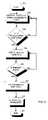
- FIG. 2is a flow diagram of a method for operating the in-vehicle information system of FIG. 1 ;
- FIG. 3is a flow diagram of a method for operating an external computer in conjunction with the in-vehicle information system of FIG. 1 .
- FIG. 1it shows a block diagram of a data processing system 100 .
- the system 100includes a host computer 102 (also referred to as a host or host processor), a telecommunication device 104 , an external computer 106 and a switch 108 .
- the system 100further includes a connector 110 , a first host universal asynchronous receiver-transmitter (UART) 112 and a second host UART 114 .
- UARTuniversal asynchronous receiver-transmitter
- the system 100is associated with a vehicle 116 . It is envisioned that the external computer 106 may be detachably coupled with the rest of the system 100 using the connector 110 .
- the vehicle 116may be an automobile, truck, tractor or other self-propelled vehicle.
- the vehicle 116includes the host computer 102 (also referred to as a host) which monitors and controls operating systems of the vehicle 116 .
- Systems controlled or monitored by the system 100 in exemplary embodimentsinclude safety systems including one or more airbags and security systems including the door locks. When an airbag is deployed, the host computer 102 detects the condition. If the doors are unlocked and should be locked because of a received actuation, the host computer 102 locks the doors. Other systems and functions may be under control of the host computer 102 in alternative embodiments.
- the host computer 102may include a processor 120 and memory 122 , along with a user interface 123 and a global positioning system (GPS) receiver 126 .
- the processor 120may be any suitable microprocessor or microcontroller or other general purpose processing apparatus. Alternatively, the processor 120 may be logic circuits interconnected to perform the functions described herein.
- the processor 120operates in conjunction with data and instructions stored in the memory 122 .
- the memory 122may be read only (non-volatile) memory such as flash or other electrically erasable read only memory, read-write (volatile) memory or any other suitable memory circuitry.
- the host computer 102is physically combined with the entertainment radio of the vehicle 116 to provide command and control of in-vehicle data processing systems.
- the user interface 123permits user control of the data processing system 100 .
- the user interface 123includes a display, a keypad, a speaker and a microphone. These and other components of the user interface 123 may be located in or near the dash of the vehicle for ease of use by the user of the data processing system 100 or operator of the vehicle 116 .
- the GPS receiver 126receives global positioning signals from satellites in earth orbit and uses the received signals to determine an approximate position for the vehicle 116 on the Earth. Position information is then conveyed to the host computer 102 for use by the host computer 102 or for communication to other receivers.
- the telecommunication device 104forms a vehicle telecommunication device for two-way voice and data communication between the vehicle 116 and a remote telecommunication device.
- the telecommunication device 104includes a radiotelephone which permits an operator of the vehicle to initiate and receive voice telephone calls.
- the telecommunication device 104includes a cellular transceiver.
- the cellular transceiverincludes all hardware and software necessary to provide two-way radio communication with one or more remote radios which is part of a cellular telephone system.
- the cellular transceiveroperates according to a predetermined data communication protocol in conjunction with the remote radios to initiate calls, receive calls and send and receive control information.
- the telecommunication devicemay operate on any suitable cellular telephone standard such as the advanced mobile phone system (AMPS) standard, a time division multiple access (TDMA) standard, a code division multiple access (CDMA) standard or other standards which may be developed.
- AMPSadvanced mobile phone system
- TDMAtime division multiple access
- CDMAcode division multiple access
- the telecommunication device 104is embodied as a satellite telephone in radio communication with one or more earth orbiting satellites.
- the telecommunication deviceoperates according to any suitable satellite standard currently existing or developed in the future.
- the telecommunication device 104may be any radio providing two-way communication of data or audio information.
- the telecommunication device 104 of the illustrated embodimentincludes a radio portion that operates according to a cellular telephone standard and a wireline portion that operates according to a wireline data communication standard.
- the chosen standardis Recommended Standard 232, “Interface Between Data Terminal Equipment and Data Circuit-Terminating Equipment Employing Serial Binary Data Interchange,” published by the Electronic Industries Association/Telecommunications Industry Association (EIA/TIA) and commonly referred to as RS-232.
- RS-232provides serial data communication over a wireline link between one device, the Data Terminal Equipment (“DTE”), such as the COM1 port of a personal computer (PC) and the Data Communication Equipment (“DCE”) such as a modem.
- DTEData Terminal Equipment
- PCpersonal computer
- DCEData Communication Equipment
- the telecommunication device 104operates as a modem to communicate data between the serial RS-232 wireline portion and the radio portion.
- RS-232 signalsThe identification and function of RS-232 signals are standardized. These signals are indicated in FIG. 1 and defined below.
- TD Transmit Datae.g., from the PC to the modem
- RD Receive Datae.g., from the modem to the PC
- RTS Request To Sende.g., PC requests permission to send data to the modem
- CTS Clear To Sende.g., modem grants permission to send
- DSR Data Set Readye.g., modem indicates that it is powered on and operational
- DCD Data Carrier Detecte.g., the modem is receiving a carrier signal from the remote modem
- DTR Data Terminal Readye.g., the PC indicates that it is powered on and operational
- the RS-232 standarddefines voltage levels and signal names.
- the telecommunication device 104operates as a modem in an RS-232 network including the host 102 and, when connected, the external computer 106 .
- the connector 110is connected internally to level shifters which internally translate voltage levels to appropriate RS-232 levels.
- the level shiftersadjust the voltage level and polarity as required.
- the logical names specified above for the signalsdo not specify the necessary signals or polarity.
- the level shifting operationis not explicitly shown in the drawing.
- the RS-232 levelsmay be describes as being asserted and negated, or using any other suitable terminology.
- the first host UART 112 and the second host UART 114operate to communicate data between the host computer 102 and the telecommunication device 104 and the external computer 106 according to the RS-232 standard.
- Each host UART 112 , 114includes a digital interface 124 for communicating digital data with a complementary host digital interface 125 of the host computer 102 .
- the digital data exchanged between these digital interfaces 124 , 125may be multiple-bit parallel data, serial data or have any other suitable format.
- the host UARTs 112 , 114each further includes a serial interface 128 , 130 respectively for communicating a serial stream of data according to the RS-232 standard, or any other information interchange standard that may be chosen for the system 100 .
- the first host UART 112forms a first host serial communication circuit and the second host UART 114 forms a second host serial communication circuit.
- the first host UART 112 and the second host UART 114may be physically integrated with the host computer 102 , for example by including the host UARTs 112 , 114 on a printed circuit board or integrated circuit included with the host computer 102 .
- the first host UART 112forms a first communication port, the serial interface 128 , having an input 132 coupled with the telecommunication device 104 and an output 134 .
- the second host UART 114forms a second communication port having an input 136 coupled with the connector 110 and an output 138 .
- the respective inputs and outputsmay be single bit or multiple bits in width.
- the external computer 106may be any type of data processing apparatus.
- the external computer 106is a portable data processing device such as a laptop computer or personal digital assistant (PDA) which may be detachably coupled to the vehicle 116 and the data processing system 100 using the connector 110 .
- PDApersonal digital assistant
- the external computer 106 in the illustrated embodimentincludes a data port 140 including an RS-232 or other modem circuit for communicating data with the data processing system 100 .
- COM1 portfor RS-232 data connection.
- Other standard or custom circuitsmay be substituted for the COM1 port.
- the illustrated embodimentmaximizes the number of external devices which may operate with the data processing system 100 while minimizing the modifications that must be made to such a system.
- the COM1 port of a PC or other external computer 106can communicate with the host computer 102 through the connector 110 .
- the connectormay be a DB-9 connector (standardized by the EIA/TIA in standard EIA/TIA-574) or a DB-25 connector, standardized in EIA/TIA-232). Any other suitable connector may be used. It is envisioned that the connector 110 will be positioned on the dash or console of the vehicle 116 for ready access by a user of the external computer 106 . To connect the external computer 106 with the data processing system 100 , the user of the external computer 106 plugs a complementary connector into the connector 110 , establishing data communication between the external computer 106 and the data processing system 100 .
- the switch 108forms a switch circuit which selectively couples one of the host computer 102 and the external computer 106 to the telecommunication device 104 in response to a control signal from the host computer 102 .
- the switch 108includes a first switch 150 and a second switch 152 .
- the switch 108receives the control signal from the host 102 at an input 154 .
- the first switch 150couples a centerpost 156 with a contact 158 .
- the first switch 150couples the centerpost 156 with a contact 160 .
- the second switch 152couples a centerpost 162 with a contact 164 .
- the second switch 152couples the centerpost 162 with a contact 166 .
- Switch positionis controlled by the control signal at the input 154 .
- the switch 108may be constructed using any suitable components.
- the switchmay be a plurality of physical switches controllable by a control signal at the input 154 .
- the switch 108may be a plurality of logic elements such as multiplexers controlled by one or more control signals at the input 154 .
- Software implementationsmay also be devised for controlling the interconnection of the elements of the data processing system 100 as functionally illustrated in FIG. 1 and described herein.
- the centerpost 156 of the first switch 150is coupled to an input 170 of the telecommunication device 104 .
- the contact 158is coupled to the output 134 of the first host UART 112 .
- the contact 160is coupled through the connector 110 to an output 172 of the external computer 106 and to an input 136 of the second host UART 114 .
- the centerpost 162 of the second switch 152is coupled through the connector 110 to an input 176 of the external computer 106 .
- the contact 164is coupled to the output 138 of the second host UART 114 .
- the contact 166is coupled to an output 174 of the telecommunication device 104 and an input 132 of the first host UART 112 .
- the connections between the switch and the other portions of the data processing system 100may be one or more bits in width. In the illustrated embodiment, the connections convey the respective RS-232 signals indicated in FIG. 1 .
- the output 138 of the second host UART 114is coupled through the second switch 152 to the connector 110 and the input 176 of the external computer 106 .
- the output 134 of the first host UART 112is coupled through the first switch 150 to the input 170 of the telecommunication device 104 .
- the output 174 of the telecommunication device 104is directly coupled to the input 132 of the first host UART 112 .
- the output 140 of the external computer 106is directly coupled through the connector 110 to the input 136 of the second host UART 114 .
- the output 174 of the telecommunication device 104is coupled through the second switch 152 and the connector 110 to the input 176 of the external computer 106 .
- the output 172 of the external computer 106is coupled through the connector 110 and the first switch 150 to the input 170 of the telecommunication device 104 .
- the output 174 of the telecommunication device 104is directly coupled to the input 132 of the first host UART 112 .
- the output 140 of the external computer 106is directly coupled through the connector 110 to the input 136 of the second host UART 114 .
- the external computer 106is connected to the telecommunication device 104 and may initiate or receive calls using the telecommunication device 104 .
- a user of the external computer 106may telephonically engage a wireless service provider to access the internet, check electronic mail or otherwise communicate data using the telecommunication device when the switch 108 is in the second position.
- Dataare transmitted and received from the external computer 106 using RS-232 format.
- the telecommunication device 104similarly communicates RS-232 formatted data and converts between RS-232 formatted data and the data format used on the wireless link established by the telecommunication device.
- the host computer 102In the first position of the switch 108 , the host computer 102 is placed in communication with the telecommunication device 104 . In this manner, the host computer 102 may transmit data to the wireless service provider when required. For example, a user of the host computer 102 may request driving directions using the user interface 124 . The request is formatted by the host computer 102 and conveyed as RS-232 data to the telecommunication device 104 . The telecommunication device 104 converts the RS-232 data to a data format for wireless communication and transmits the request over a radio link. When a response or any other communication is received from a remote radio and intended for the vehicle 116 , the response or other communication is converted to RS-232 data and communicated to the host 102 .
- a direct connectionis maintained between the output 172 of the external computer 106 and the input 136 of the second host UART 114 .
- the host computer 102detects the presence of the RS-232 signal DTR from the external computer 106 using this connection.
- the external computer 106transmits the signal DTR when the external computer is powered up and it is operational. If the data communication circuit of the external computer 106 is not active, the signal DTR will not be asserted or will be transmitted with a logic low value.
- the host computer 102in response generates the control signal at the input 154 of the switch 108 to switch the switch to position 2 . This connects the external computer 106 to the telecommunication device 104 .
- the external computer 106selectively originates a ready control signal in the form of the DTR signal.
- the host 102is configured to receive the ready control signal and produce a control signal, the control signal at the input 154 of the switch 108 , in response thereto.
- the illustrated embodimentallows the host computer 102 to apply the appropriate control signal at the input 154 to switch the switch 108 to position 1 .
- This switch positionconnects the telecommunication device 104 to the first host UART 112 and connects the external computer 106 to the second host UART 114 .
- the host computer 102may be programmed to detect the airbag status and automatically initiate a call using the telecommunication device to a service provider to summon emergency help. If a call is under way from the external computer 106 plugged into the connector 110 to access the telecommunication device 104 , the connection between the external computer 106 and the telecommunication device 104 is interrupted as the emergency condition is given a higher priority by switching the switch 108 to position 1 .
- RS-232 data connectionsmay be maintained as normal in the illustrated embodiment.
- the external computer 106detects signals communicated by the host computer 102 .
- the telecommunication device 104detects the signals communicated by the host computer 102 .
- the switch 108is actuated, the host computer 102 controls communication with the telecommunication device 104 and the external computer. This includes communication of data as well as communication of control signals.
- the host computer 102can negate the signal DCD or data carrier detect to interrupt the connection to the external computer.
- FIG. 2is a flow diagram illustrating a method for operating the in-vehicle data processing system 100 of FIG. 1 .
- the method of FIG. 2is performed in the host computer 102 of the data processing system 100 .
- the methodbegins at block 200 .
- the host computer 102places the switch 108 in a default position, position 1 as shown in the embodiment of FIG. 1 . This position connects the telecommunication device 104 to the host computer 102 .
- the host computer 102determines if it receives a ready control signal such as the RS-232 signal DTR from the external computer 106 . If not, control returns to block 202 . If the ready control signal is received, at block 206 the host computer 102 switches the multiplexer or other device forming the switch 108 to position 2 . In position 2 , the external computer 106 is connected for two-way communication with the telecommunication device 104 .
- the host computer 102waits for an interrupt event.
- the interrupt eventis any event of a higher priority than the on-going communication or connection between the external computer 106 and the telecommunication device 104 , particularly an event which requires use of the telecommunication device 104 by the host 102 for transmission or reception of information.
- An exampleis a detected deployment of the vehicle airbag, indicating that an emergency service provider should be contacted.
- Another exampleis actuation of the user interface 124 of the host computer 102 by a user to access data remotely using the telecommunication device 104 , for example a request for driving directions.
- controlremains in a loop including blocks 206 , 208 and the host computer 102 maintains the switch 108 in position 2 . If, however, an interrupt event is detected, control proceeds to block 210 .
- the host computer 102asserts the appropriate signals to the switch 108 to place the switch 108 in position 1 .
- the communicationis interrupted without loss of data and by returning the telecommunication device 104 and the external computer 106 to initial states for further operation.
- the host computer 102initiates a call using the telecommunication device 104 .
- the methodends at block 214 .
- FIG. 3is a flow diagram illustrating a method for operating an external computer 106 in conjunction with the in-vehicle data processing system 100 of FIG. 1 .
- FIG. 3illustrates operation of a personal computer (PC) which includes an RS-232 serial port for remote wireline data communication according to the RS-232 standard. The method begins at block 300 .
- PCpersonal computer
- the external computer 106is initialized. Initialization generally involves powering on the external computer 106 , loading applications programs, resetting devices such as serial communications ports to initial states and entering a state awaiting user input.
- the external computer 106 and its RS-232 portbecome operational and at block 306 the port transmits the DTR signal. This may take the form of changing the data state of the DTR signal from a negated state to an asserted state. More specifically, as defined by the RS-232 standard, this may involve switching the voltage on the wire designated as DTR from a negative voltage between ⁇ 3 and ⁇ 25 volts to a positive voltage between +3 and +25 volts.
- the DTR signalforms a ready control signal from the external computer 106 to the host computer 102 .
- the external computer 106determines if it can access the telecommunication device 104 of the data processing system 100 of FIG. 1 .
- the external computer 106will not be able to access the telecommunication device 104 if the host computer 102 of the data processing system does not place the switch in position 2 in response to the ready control signal, DTR. If the external computer 106 can not access the telecommunication device 104 , control returns to block 304 and the external computer 106 may retry to access the telecommunication device 104 or may discontinue such attempts.
- the external computer 106If the external computer 106 can access the telecommunication device 104 , at block 310 the external computer 106 transmits the RS-232 signal RTS or Request To Send to telecommunication device 104 , indicating that it has data for transmission to the telecommunication device 104 .
- the signal RTSmay be received by the host computer 102 .
- the external computer 106determines if the RS-232 signal CTS or Clear To Send is received from the telecommunication device 104 . If not, in a loop including block 310 and block 312 , the external computer 106 continues to transmit RTS and listen for CTS. If the signal CTS is received from the telecommunication device 104 , at block 314 data is sent to the telecommunication device 104 according to the RS-232 standard.
- the external computerdetermines if there is additional data to send or if the end of the data has been reached. If there is additional data to send, control returns to block 312 to ensure the CTS signal is received from the telecommunication device. If the host switched the switch position from position 2 to position 1 , the CTS signal will no longer be present. Alternatively, the DSR or DTR signals may be used to determine status. If the end of the data has been reached, control returns to block 304 . If the remote end of the connection hangs up, the signal DCD will be negated.
- the present embodimentsprovide a method and apparatus for prioritizing access to a shared telecommunication resource in a data processing system.
- the external computeris given priority when its ready control signal is detected by the host. However, if a higher priority communication must be made, the host actuates a switch to disconnect the external computer and begin communicating directly with the telecommunication resource. Communication occurs according to a predefined standard such as RS-232 so that conventional devices such as laptop PCs can be readily connected to the data processing system without modification. If connection to the external computer is interrupted, the predefined standard ensures that the devices will enter controlled states for further processing.
Landscapes
- Engineering & Computer Science (AREA)
- Computer Networks & Wireless Communication (AREA)
- Signal Processing (AREA)
- Mobile Radio Communication Systems (AREA)
Abstract
Description
| Signal | Function | ||
| TD | Transmit Data (e.g., from the PC to the modem) | ||
| RD | Receive Data (e.g., from the modem to the PC) | ||
| RTS | Request To Send (e.g., PC requests permission | ||
| to send data to the modem) | |||
| CTS | Clear To Send (e.g., modem grants permission | ||
| to send) | |||
| DSR | Data Set Ready (e.g., modem indicates that it is | ||
| powered on and operational) | |||
| DCD | Data Carrier Detect (e.g., the modem is | ||
| receiving a carrier signal from the remote | |||
| modem) | |||
| DTR | Data Terminal Ready (e.g., the PC indicates that | ||
| it is powered on and operational) | |||
Claims (7)
Priority Applications (3)
| Application Number | Priority Date | Filing Date | Title |
|---|---|---|---|
| US10/036,922US7130300B2 (en) | 2001-12-21 | 2001-12-21 | Use of phone—UART multiplexer to create low software overhead external access to internal data modem with wireless communications and phone |
| GB0226423AGB2383727B (en) | 2001-12-21 | 2002-11-13 | Use of phone-UART multiplexer to create low software overhead external access to internal data modem with wireless communications and phone |
| DE10259611ADE10259611A1 (en) | 2001-12-21 | 2002-12-13 | Use of a telephone UART multiplexer to create a low-program external access to an internal data modem through wireless messaging and telephone |
Applications Claiming Priority (1)
| Application Number | Priority Date | Filing Date | Title |
|---|---|---|---|
| US10/036,922US7130300B2 (en) | 2001-12-21 | 2001-12-21 | Use of phone—UART multiplexer to create low software overhead external access to internal data modem with wireless communications and phone |
Publications (2)
| Publication Number | Publication Date |
|---|---|
| US20030118055A1 US20030118055A1 (en) | 2003-06-26 |
| US7130300B2true US7130300B2 (en) | 2006-10-31 |
Family
ID=21891416
Family Applications (1)
| Application Number | Title | Priority Date | Filing Date |
|---|---|---|---|
| US10/036,922Expired - LifetimeUS7130300B2 (en) | 2001-12-21 | 2001-12-21 | Use of phone—UART multiplexer to create low software overhead external access to internal data modem with wireless communications and phone |
Country Status (3)
| Country | Link |
|---|---|
| US (1) | US7130300B2 (en) |
| DE (1) | DE10259611A1 (en) |
| GB (1) | GB2383727B (en) |
Families Citing this family (1)
| Publication number | Priority date | Publication date | Assignee | Title |
|---|---|---|---|---|
| TWM249116U (en)* | 2004-01-08 | 2004-11-01 | Uis Abler Electronics Co Ltd | Switching device for RS-232 serial port and USB serial port |
Citations (16)
| Publication number | Priority date | Publication date | Assignee | Title |
|---|---|---|---|---|
| US3988543A (en) | 1974-04-02 | 1976-10-26 | Cselt - Centro Studi E Laboratori Telecomunicazioni | Inter-office signaling system for telecommunication network |
| US5301186A (en)* | 1991-06-28 | 1994-04-05 | Digital Equipment Corporation | High speed transmission line interface |
| US5680403A (en) | 1995-12-14 | 1997-10-21 | Pitney Bowes Inc. | Multiplex serial data communications with a single UART for a postage meter mailing machine system |
| US5732074A (en)* | 1996-01-16 | 1998-03-24 | Cellport Labs, Inc. | Mobile portable wireless communication system |
| US5799208A (en) | 1996-04-03 | 1998-08-25 | United Microelectronics Corporation | Apparatus for data communication between universal asynchronous receiver/transmitter (UART) modules and transceivers in a chip set by selectively connecting a common bus between multiplexer/demultiplexer units |
| US6011460A (en)* | 1996-08-22 | 2000-01-04 | Flick; Kenneth E. | Vehicle security system for a vehicle having a data communications bus and related methods |
| US6023232A (en) | 1996-06-22 | 2000-02-08 | Daimlerchrysler Ag | Vehicle communications system and method |
| US6061561A (en) | 1996-10-11 | 2000-05-09 | Nokia Mobile Phones Limited | Cellular communication system providing cell transmitter location information |
| US6133853A (en)* | 1998-07-30 | 2000-10-17 | American Calcar, Inc. | Personal communication and positioning system |
| US6167255A (en)* | 1998-07-29 | 2000-12-26 | @Track Communications, Inc. | System and method for providing menu data using a communication network |
| US20020154605A1 (en)* | 2001-04-24 | 2002-10-24 | Medius, Inc. | Method and apparatus for dynamic configuration of multiprocessor system |
| US20020156564A1 (en)* | 2001-04-24 | 2002-10-24 | Medius, Inc. | Open communication system for real-time multiprocessor applications |
| US6518855B1 (en) | 1998-03-11 | 2003-02-11 | Infineon Technologies Ag | Integrated circuit for mobile radio and mobile telephone installations |
| US6526335B1 (en)* | 2000-01-24 | 2003-02-25 | G. Victor Treyz | Automobile personal computer systems |
| US6707421B1 (en)* | 1997-08-19 | 2004-03-16 | Siemens Vdo Automotive Corporation | Driver information system |
| US6941194B1 (en) | 1998-11-20 | 2005-09-06 | Siemens Aktiengesellschaft | Motor vehicle communication system and method for exchanging data in a motor vehicle |
Family Cites Families (11)
| Publication number | Priority date | Publication date | Assignee | Title |
|---|---|---|---|---|
| US6334061B1 (en)* | 1994-12-21 | 2001-12-25 | Itt Manufacturing Enterprises, Inc. | Integrated vehicle applique unit for the position enhanced cellular system |
| US5768691A (en)* | 1996-08-07 | 1998-06-16 | Nokia Mobile Phones Limited | Antenna switching circuits for radio telephones |
| US6064982A (en)* | 1997-11-12 | 2000-05-16 | Netscape Communication Corporation | Smart configurator |
| JP3126695B2 (en)* | 1998-02-27 | 2001-01-22 | 松下電器産業株式会社 | Emergency emergency call device with external device communication function |
| KR100311454B1 (en)* | 1998-06-27 | 2002-02-28 | 전주범 | Conversion method and apparatus of bill of parts of a printed circuit board |
| DE19833665A1 (en)* | 1998-07-27 | 2000-02-03 | Bosch Gmbh Robert | Device for connecting a wiper blade for windows of motor vehicles to a driven wiper arm guided at one end on the motor vehicle |
| US6223094B1 (en)* | 1998-08-21 | 2001-04-24 | Sap Aktiengesellschaft | Multi-tiered structure for storing and displaying product and process variants |
| US6061691A (en)* | 1998-08-31 | 2000-05-09 | Maxagrid International, Inc. | Method and system for inventory management |
| CA2393395A1 (en)* | 1999-12-01 | 2001-06-07 | Sinex Aviation Technologies Corporation | Dynamic aircraft maintenance management system |
| US7406431B2 (en)* | 2000-03-17 | 2008-07-29 | Siemens Aktiengesellschaft | Plant maintenance technology architecture |
| US20010032109A1 (en)* | 2000-04-13 | 2001-10-18 | Gonyea Richard Jeremiah | System and method for predicting a maintenance schedule and costs for performing future service events of a product |
- 2001
- 2001-12-21USUS10/036,922patent/US7130300B2/ennot_activeExpired - Lifetime
- 2002
- 2002-11-13GBGB0226423Apatent/GB2383727B/ennot_activeExpired - Fee Related
- 2002-12-13DEDE10259611Apatent/DE10259611A1/ennot_activeWithdrawn
Patent Citations (16)
| Publication number | Priority date | Publication date | Assignee | Title |
|---|---|---|---|---|
| US3988543A (en) | 1974-04-02 | 1976-10-26 | Cselt - Centro Studi E Laboratori Telecomunicazioni | Inter-office signaling system for telecommunication network |
| US5301186A (en)* | 1991-06-28 | 1994-04-05 | Digital Equipment Corporation | High speed transmission line interface |
| US5680403A (en) | 1995-12-14 | 1997-10-21 | Pitney Bowes Inc. | Multiplex serial data communications with a single UART for a postage meter mailing machine system |
| US5732074A (en)* | 1996-01-16 | 1998-03-24 | Cellport Labs, Inc. | Mobile portable wireless communication system |
| US5799208A (en) | 1996-04-03 | 1998-08-25 | United Microelectronics Corporation | Apparatus for data communication between universal asynchronous receiver/transmitter (UART) modules and transceivers in a chip set by selectively connecting a common bus between multiplexer/demultiplexer units |
| US6023232A (en) | 1996-06-22 | 2000-02-08 | Daimlerchrysler Ag | Vehicle communications system and method |
| US6011460A (en)* | 1996-08-22 | 2000-01-04 | Flick; Kenneth E. | Vehicle security system for a vehicle having a data communications bus and related methods |
| US6061561A (en) | 1996-10-11 | 2000-05-09 | Nokia Mobile Phones Limited | Cellular communication system providing cell transmitter location information |
| US6707421B1 (en)* | 1997-08-19 | 2004-03-16 | Siemens Vdo Automotive Corporation | Driver information system |
| US6518855B1 (en) | 1998-03-11 | 2003-02-11 | Infineon Technologies Ag | Integrated circuit for mobile radio and mobile telephone installations |
| US6167255A (en)* | 1998-07-29 | 2000-12-26 | @Track Communications, Inc. | System and method for providing menu data using a communication network |
| US6133853A (en)* | 1998-07-30 | 2000-10-17 | American Calcar, Inc. | Personal communication and positioning system |
| US6941194B1 (en) | 1998-11-20 | 2005-09-06 | Siemens Aktiengesellschaft | Motor vehicle communication system and method for exchanging data in a motor vehicle |
| US6526335B1 (en)* | 2000-01-24 | 2003-02-25 | G. Victor Treyz | Automobile personal computer systems |
| US20020154605A1 (en)* | 2001-04-24 | 2002-10-24 | Medius, Inc. | Method and apparatus for dynamic configuration of multiprocessor system |
| US20020156564A1 (en)* | 2001-04-24 | 2002-10-24 | Medius, Inc. | Open communication system for real-time multiprocessor applications |
Non-Patent Citations (3)
| Title |
|---|
| Halsall, Data communications, computer networks and Open systems, Addison-Wesley, 1995, pp. 1, 2, 82 and 83.* |
| ITU/CCITT-EIA-Bell RS-232, Ionestar.org, pp. 1-4.* |
| Mikiya, Emergency accident reporting device with external device communication function. 1999-250378. English translation. pp. 1-12.* |
Also Published As
| Publication number | Publication date |
|---|---|
| US20030118055A1 (en) | 2003-06-26 |
| GB2383727B (en) | 2004-02-25 |
| GB2383727A (en) | 2003-07-02 |
| GB0226423D0 (en) | 2002-12-18 |
| DE10259611A1 (en) | 2003-07-10 |
Similar Documents
| Publication | Publication Date | Title |
|---|---|---|
| EP1454459B1 (en) | Method of and system for coupling location information | |
| EP0699361B1 (en) | Method and apparatus for transmission of data using radio frequency signals | |
| US8892172B2 (en) | Method of enabling a remote communications device with a telematics functionality module | |
| JP4828798B2 (en) | Electronics | |
| US20040203370A1 (en) | Wireless gateway node | |
| JPH07303283A (en) | Assembly of radio trans mission system in radioc communication system | |
| US6973378B2 (en) | In-vehicle control device communicatable with external communication system and in-vehicle LAN | |
| WO2000044186A1 (en) | Automatic sensing of communication or accessories for mobile terminals | |
| US5214774A (en) | Segmented memory transfer and message priority on synchronous/asynchronous data bus | |
| KR100302924B1 (en) | Improvements in data communications | |
| US7130300B2 (en) | Use of phone—UART multiplexer to create low software overhead external access to internal data modem with wireless communications and phone | |
| AU8326991A (en) | Multiplexed synchronous/asynchronous data bus | |
| US5732335A (en) | Externally controlled output power by means of antenna keying | |
| US7162270B2 (en) | Dual communication mode wireless network transmission device | |
| JPH06104826A (en) | Wireless telephone | |
| CN117296349A (en) | Modular telematics control unit and motor vehicle equipped with such a telematics control unit | |
| WO2009084746A1 (en) | Telematics having the changable communication module | |
| US20020013148A1 (en) | Telephone set identifying method, telephone set type identifying apparatus, processing apparatus and storage medium | |
| US20070002891A1 (en) | In-vehicle wireless device | |
| US8200154B2 (en) | System, apparatus and method to control output of radio frequency signal | |
| US20050227741A1 (en) | Method for controlling a hands free system, radio apparatus, and hands free apparatus | |
| JPH10126839A (en) | Satellite communication terminal set having attachable/ detachable handset cradle | |
| KR20090070190A (en) | Communication module replaceable telematics terminal | |
| US20040199673A1 (en) | Electronic peripheral device and network card | |
| KR20030060706A (en) | Method for connecting and disconnecting internet for urgent message transmission in telematics |
Legal Events
| Date | Code | Title | Description |
|---|---|---|---|
| AS | Assignment | Owner name:VISTEON GLOBAL TECHNOLOGIES, INC., MICHIGAN Free format text:ASSIGNMENT OF ASSIGNORS INTEREST;ASSIGNORS:FECHER, DANA B.;MILNE, GREGORY J.;WILLIAMS, GREGORY H.;REEL/FRAME:012705/0886;SIGNING DATES FROM 20011219 TO 20020107 | |
| STCF | Information on status: patent grant | Free format text:PATENTED CASE | |
| AS | Assignment | Owner name:JPMORGAN CHASE BANK, N.A., AS ADMINISTRATIVE AGENT Free format text:SECURITY AGREEMENT;ASSIGNOR:VISTEON GLOBAL TECHNOLOGIES, INC.;REEL/FRAME:020497/0733 Effective date:20060613 | |
| AS | Assignment | Owner name:JPMORGAN CHASE BANK, TEXAS Free format text:SECURITY INTEREST;ASSIGNOR:VISTEON GLOBAL TECHNOLOGIES, INC.;REEL/FRAME:022368/0001 Effective date:20060814 Owner name:JPMORGAN CHASE BANK,TEXAS Free format text:SECURITY INTEREST;ASSIGNOR:VISTEON GLOBAL TECHNOLOGIES, INC.;REEL/FRAME:022368/0001 Effective date:20060814 | |
| AS | Assignment | Owner name:WILMINGTON TRUST FSB, AS ADMINISTRATIVE AGENT, MIN Free format text:ASSIGNMENT OF SECURITY INTEREST IN PATENTS;ASSIGNOR:JPMORGAN CHASE BANK, N.A., AS ADMINISTRATIVE AGENT;REEL/FRAME:022575/0186 Effective date:20090415 Owner name:WILMINGTON TRUST FSB, AS ADMINISTRATIVE AGENT,MINN Free format text:ASSIGNMENT OF SECURITY INTEREST IN PATENTS;ASSIGNOR:JPMORGAN CHASE BANK, N.A., AS ADMINISTRATIVE AGENT;REEL/FRAME:022575/0186 Effective date:20090415 | |
| AS | Assignment | Owner name:THE BANK OF NEW YORK MELLON, AS ADMINISTRATIVE AGE Free format text:ASSIGNMENT OF PATENT SECURITY INTEREST;ASSIGNOR:JPMORGAN CHASE BANK, N.A., A NATIONAL BANKING ASSOCIATION;REEL/FRAME:022974/0057 Effective date:20090715 | |
| FPAY | Fee payment | Year of fee payment:4 | |
| AS | Assignment | Owner name:VISTEON GLOBAL TECHNOLOGIES, INC., MICHIGAN Free format text:RELEASE BY SECURED PARTY AGAINST SECURITY INTEREST IN PATENTS RECORDED AT REEL 022974 FRAME 0057;ASSIGNOR:THE BANK OF NEW YORK MELLON;REEL/FRAME:025095/0711 Effective date:20101001 | |
| AS | Assignment | Owner name:VISTEON GLOBAL TECHNOLOGIES, INC., MICHIGAN Free format text:RELEASE BY SECURED PARTY AGAINST SECURITY INTEREST IN PATENTS RECORDED AT REEL 022575 FRAME 0186;ASSIGNOR:WILMINGTON TRUST FSB, AS ADMINISTRATIVE AGENT;REEL/FRAME:025105/0201 Effective date:20101001 | |
| AS | Assignment | Owner name:MORGAN STANLEY SENIOR FUNDING, INC., AS AGENT, NEW Free format text:SECURITY AGREEMENT;ASSIGNORS:VISTEON CORPORATION;VC AVIATION SERVICES, LLC;VISTEON ELECTRONICS CORPORATION;AND OTHERS;REEL/FRAME:025241/0317 Effective date:20101007 Owner name:MORGAN STANLEY SENIOR FUNDING, INC., AS AGENT, NEW Free format text:SECURITY AGREEMENT (REVOLVER);ASSIGNORS:VISTEON CORPORATION;VC AVIATION SERVICES, LLC;VISTEON ELECTRONICS CORPORATION;AND OTHERS;REEL/FRAME:025238/0298 Effective date:20101001 | |
| AS | Assignment | Owner name:VISTEON CORPORATION, MICHIGAN Free format text:RELEASE BY SECURED PARTY AGAINST SECURITY INTEREST IN PATENTS ON REEL 025241 FRAME 0317;ASSIGNOR:MORGAN STANLEY SENIOR FUNDING, INC.;REEL/FRAME:026178/0412 Effective date:20110406 Owner name:VISTEON SYSTEMS, LLC, MICHIGAN Free format text:RELEASE BY SECURED PARTY AGAINST SECURITY INTEREST IN PATENTS ON REEL 025241 FRAME 0317;ASSIGNOR:MORGAN STANLEY SENIOR FUNDING, INC.;REEL/FRAME:026178/0412 Effective date:20110406 Owner name:VISTEON EUROPEAN HOLDING, INC., MICHIGAN Free format text:RELEASE BY SECURED PARTY AGAINST SECURITY INTEREST IN PATENTS ON REEL 025241 FRAME 0317;ASSIGNOR:MORGAN STANLEY SENIOR FUNDING, INC.;REEL/FRAME:026178/0412 Effective date:20110406 Owner name:VISTEON GLOBAL TREASURY, INC., MICHIGAN Free format text:RELEASE BY SECURED PARTY AGAINST SECURITY INTEREST IN PATENTS ON REEL 025241 FRAME 0317;ASSIGNOR:MORGAN STANLEY SENIOR FUNDING, INC.;REEL/FRAME:026178/0412 Effective date:20110406 Owner name:VISTEON INTERNATIONAL BUSINESS DEVELOPMENT, INC., Free format text:RELEASE BY SECURED PARTY AGAINST SECURITY INTEREST IN PATENTS ON REEL 025241 FRAME 0317;ASSIGNOR:MORGAN STANLEY SENIOR FUNDING, INC.;REEL/FRAME:026178/0412 Effective date:20110406 Owner name:VISTEON INTERNATIONAL HOLDINGS, INC., MICHIGAN Free format text:RELEASE BY SECURED PARTY AGAINST SECURITY INTEREST IN PATENTS ON REEL 025241 FRAME 0317;ASSIGNOR:MORGAN STANLEY SENIOR FUNDING, INC.;REEL/FRAME:026178/0412 Effective date:20110406 Owner name:VISTEON GLOBAL TECHNOLOGIES, INC., MICHIGAN Free format text:RELEASE BY SECURED PARTY AGAINST SECURITY INTEREST IN PATENTS ON REEL 025241 FRAME 0317;ASSIGNOR:MORGAN STANLEY SENIOR FUNDING, INC.;REEL/FRAME:026178/0412 Effective date:20110406 Owner name:VISTEON ELECTRONICS CORPORATION, MICHIGAN Free format text:RELEASE BY SECURED PARTY AGAINST SECURITY INTEREST IN PATENTS ON REEL 025241 FRAME 0317;ASSIGNOR:MORGAN STANLEY SENIOR FUNDING, INC.;REEL/FRAME:026178/0412 Effective date:20110406 Owner name:VC AVIATION SERVICES, LLC, MICHIGAN Free format text:RELEASE BY SECURED PARTY AGAINST SECURITY INTEREST IN PATENTS ON REEL 025241 FRAME 0317;ASSIGNOR:MORGAN STANLEY SENIOR FUNDING, INC.;REEL/FRAME:026178/0412 Effective date:20110406 | |
| FPAY | Fee payment | Year of fee payment:8 | |
| AS | Assignment | Owner name:CITIBANK., N.A., AS ADMINISTRATIVE AGENT, NEW YORK Free format text:SECURITY INTEREST;ASSIGNORS:VISTEON CORPORATION, AS GRANTOR;VISTEON GLOBAL TECHNOLOGIES, INC., AS GRANTOR;REEL/FRAME:032713/0065 Effective date:20140409 | |
| AS | Assignment | Owner name:VISTEON EUROPEAN HOLDINGS, INC., MICHIGAN Free format text:RELEASE OF SECURITY INTEREST IN INTELLECTUAL PROPERTY;ASSIGNOR:MORGAN STANLEY SENIOR FUNDING, INC.;REEL/FRAME:033107/0717 Effective date:20140409 Owner name:VISTEON INTERNATIONAL BUSINESS DEVELOPMENT, INC., Free format text:RELEASE OF SECURITY INTEREST IN INTELLECTUAL PROPERTY;ASSIGNOR:MORGAN STANLEY SENIOR FUNDING, INC.;REEL/FRAME:033107/0717 Effective date:20140409 Owner name:VISTEON GLOBAL TECHNOLOGIES, INC., MICHIGAN Free format text:RELEASE OF SECURITY INTEREST IN INTELLECTUAL PROPERTY;ASSIGNOR:MORGAN STANLEY SENIOR FUNDING, INC.;REEL/FRAME:033107/0717 Effective date:20140409 Owner name:VISTEON GLOBAL TREASURY, INC., MICHIGAN Free format text:RELEASE OF SECURITY INTEREST IN INTELLECTUAL PROPERTY;ASSIGNOR:MORGAN STANLEY SENIOR FUNDING, INC.;REEL/FRAME:033107/0717 Effective date:20140409 Owner name:VISTEON ELECTRONICS CORPORATION, MICHIGAN Free format text:RELEASE OF SECURITY INTEREST IN INTELLECTUAL PROPERTY;ASSIGNOR:MORGAN STANLEY SENIOR FUNDING, INC.;REEL/FRAME:033107/0717 Effective date:20140409 Owner name:VISTEON CORPORATION, MICHIGAN Free format text:RELEASE OF SECURITY INTEREST IN INTELLECTUAL PROPERTY;ASSIGNOR:MORGAN STANLEY SENIOR FUNDING, INC.;REEL/FRAME:033107/0717 Effective date:20140409 Owner name:VISTEON INTERNATIONAL HOLDINGS, INC., MICHIGAN Free format text:RELEASE OF SECURITY INTEREST IN INTELLECTUAL PROPERTY;ASSIGNOR:MORGAN STANLEY SENIOR FUNDING, INC.;REEL/FRAME:033107/0717 Effective date:20140409 Owner name:VC AVIATION SERVICES, LLC, MICHIGAN Free format text:RELEASE OF SECURITY INTEREST IN INTELLECTUAL PROPERTY;ASSIGNOR:MORGAN STANLEY SENIOR FUNDING, INC.;REEL/FRAME:033107/0717 Effective date:20140409 Owner name:VISTEON SYSTEMS, LLC, MICHIGAN Free format text:RELEASE OF SECURITY INTEREST IN INTELLECTUAL PROPERTY;ASSIGNOR:MORGAN STANLEY SENIOR FUNDING, INC.;REEL/FRAME:033107/0717 Effective date:20140409 | |
| FEPP | Fee payment procedure | Free format text:PAYOR NUMBER ASSIGNED (ORIGINAL EVENT CODE: ASPN); ENTITY STATUS OF PATENT OWNER: LARGE ENTITY | |
| MAFP | Maintenance fee payment | Free format text:PAYMENT OF MAINTENANCE FEE, 12TH YEAR, LARGE ENTITY (ORIGINAL EVENT CODE: M1553) Year of fee payment:12 |