US7129731B2 - Heat pipe with chilled liquid condenser system for burn-in testing - Google Patents
Heat pipe with chilled liquid condenser system for burn-in testingDownload PDFInfo
- Publication number
- US7129731B2 US7129731B2US10/929,869US92986904AUS7129731B2US 7129731 B2US7129731 B2US 7129731B2US 92986904 AUS92986904 AUS 92986904AUS 7129731 B2US7129731 B2US 7129731B2
- Authority
- US
- United States
- Prior art keywords
- coils
- exterior surface
- heat pipe
- coolant
- open end
- Prior art date
- Legal status (The legal status is an assumption and is not a legal conclusion. Google has not performed a legal analysis and makes no representation as to the accuracy of the status listed.)
- Expired - Fee Related, expires
Links
Images


Classifications
- G—PHYSICS
- G01—MEASURING; TESTING
- G01R—MEASURING ELECTRIC VARIABLES; MEASURING MAGNETIC VARIABLES
- G01R31/00—Arrangements for testing electric properties; Arrangements for locating electric faults; Arrangements for electrical testing characterised by what is being tested not provided for elsewhere
- G01R31/28—Testing of electronic circuits, e.g. by signal tracer
- G01R31/2851—Testing of integrated circuits [IC]
- G01R31/2855—Environmental, reliability or burn-in testing
- G01R31/2872—Environmental, reliability or burn-in testing related to electrical or environmental aspects, e.g. temperature, humidity, vibration, nuclear radiation
- G01R31/2874—Environmental, reliability or burn-in testing related to electrical or environmental aspects, e.g. temperature, humidity, vibration, nuclear radiation related to temperature
- G01R31/2875—Environmental, reliability or burn-in testing related to electrical or environmental aspects, e.g. temperature, humidity, vibration, nuclear radiation related to temperature related to heating
- F—MECHANICAL ENGINEERING; LIGHTING; HEATING; WEAPONS; BLASTING
- F25—REFRIGERATION OR COOLING; COMBINED HEATING AND REFRIGERATION SYSTEMS; HEAT PUMP SYSTEMS; MANUFACTURE OR STORAGE OF ICE; LIQUEFACTION SOLIDIFICATION OF GASES
- F25B—REFRIGERATION MACHINES, PLANTS OR SYSTEMS; COMBINED HEATING AND REFRIGERATION SYSTEMS; HEAT PUMP SYSTEMS
- F25B23/00—Machines, plants or systems, with a single mode of operation not covered by groups F25B1/00 - F25B21/00, e.g. using selective radiation effect
- F25B23/006—Machines, plants or systems, with a single mode of operation not covered by groups F25B1/00 - F25B21/00, e.g. using selective radiation effect boiling cooling systems
- F—MECHANICAL ENGINEERING; LIGHTING; HEATING; WEAPONS; BLASTING
- F28—HEAT EXCHANGE IN GENERAL
- F28D—HEAT-EXCHANGE APPARATUS, NOT PROVIDED FOR IN ANOTHER SUBCLASS, IN WHICH THE HEAT-EXCHANGE MEDIA DO NOT COME INTO DIRECT CONTACT
- F28D1/00—Heat-exchange apparatus having stationary conduit assemblies for one heat-exchange medium only, the media being in contact with different sides of the conduit wall, in which the other heat-exchange medium is a large body of fluid, e.g. domestic or motor car radiators
- F28D1/06—Heat-exchange apparatus having stationary conduit assemblies for one heat-exchange medium only, the media being in contact with different sides of the conduit wall, in which the other heat-exchange medium is a large body of fluid, e.g. domestic or motor car radiators with the heat-exchange conduits forming part of, or being attached to, the tank containing the body of fluid
- F—MECHANICAL ENGINEERING; LIGHTING; HEATING; WEAPONS; BLASTING
- F28—HEAT EXCHANGE IN GENERAL
- F28D—HEAT-EXCHANGE APPARATUS, NOT PROVIDED FOR IN ANOTHER SUBCLASS, IN WHICH THE HEAT-EXCHANGE MEDIA DO NOT COME INTO DIRECT CONTACT
- F28D15/00—Heat-exchange apparatus with the intermediate heat-transfer medium in closed tubes passing into or through the conduit walls ; Heat-exchange apparatus employing intermediate heat-transfer medium or bodies
- F28D15/02—Heat-exchange apparatus with the intermediate heat-transfer medium in closed tubes passing into or through the conduit walls ; Heat-exchange apparatus employing intermediate heat-transfer medium or bodies in which the medium condenses and evaporates, e.g. heat pipes
- F28D15/04—Heat-exchange apparatus with the intermediate heat-transfer medium in closed tubes passing into or through the conduit walls ; Heat-exchange apparatus employing intermediate heat-transfer medium or bodies in which the medium condenses and evaporates, e.g. heat pipes with tubes having a capillary structure
- F28D15/043—Heat-exchange apparatus with the intermediate heat-transfer medium in closed tubes passing into or through the conduit walls ; Heat-exchange apparatus employing intermediate heat-transfer medium or bodies in which the medium condenses and evaporates, e.g. heat pipes with tubes having a capillary structure forming loops, e.g. capillary pumped loops
- F—MECHANICAL ENGINEERING; LIGHTING; HEATING; WEAPONS; BLASTING
- F28—HEAT EXCHANGE IN GENERAL
- F28D—HEAT-EXCHANGE APPARATUS, NOT PROVIDED FOR IN ANOTHER SUBCLASS, IN WHICH THE HEAT-EXCHANGE MEDIA DO NOT COME INTO DIRECT CONTACT
- F28D15/00—Heat-exchange apparatus with the intermediate heat-transfer medium in closed tubes passing into or through the conduit walls ; Heat-exchange apparatus employing intermediate heat-transfer medium or bodies
- F28D15/02—Heat-exchange apparatus with the intermediate heat-transfer medium in closed tubes passing into or through the conduit walls ; Heat-exchange apparatus employing intermediate heat-transfer medium or bodies in which the medium condenses and evaporates, e.g. heat pipes
- F28D15/04—Heat-exchange apparatus with the intermediate heat-transfer medium in closed tubes passing into or through the conduit walls ; Heat-exchange apparatus employing intermediate heat-transfer medium or bodies in which the medium condenses and evaporates, e.g. heat pipes with tubes having a capillary structure
- F28D15/046—Heat-exchange apparatus with the intermediate heat-transfer medium in closed tubes passing into or through the conduit walls ; Heat-exchange apparatus employing intermediate heat-transfer medium or bodies in which the medium condenses and evaporates, e.g. heat pipes with tubes having a capillary structure characterised by the material or the construction of the capillary structure
- F—MECHANICAL ENGINEERING; LIGHTING; HEATING; WEAPONS; BLASTING
- F25—REFRIGERATION OR COOLING; COMBINED HEATING AND REFRIGERATION SYSTEMS; HEAT PUMP SYSTEMS; MANUFACTURE OR STORAGE OF ICE; LIQUEFACTION SOLIDIFICATION OF GASES
- F25B—REFRIGERATION MACHINES, PLANTS OR SYSTEMS; COMBINED HEATING AND REFRIGERATION SYSTEMS; HEAT PUMP SYSTEMS
- F25B39/00—Evaporators; Condensers
- F25B39/02—Evaporators
Definitions
- the present inventiongenerally relates to thermal management systems for semiconductor devices and, more particularly, to systems for cooling such semiconductor devices during burn-in testing.
- each semiconductor wafercan contain many individual electronic devices or electronic circuits, which are known as dies.
- Each dieis electrically tested by connecting it to special purpose test equipment.
- Probeswhich are connected to the test equipment, are brought into contact with the die to be tested. This generally occurs at a prober station, which conventionally includes a platform arranged for supporting the wafer. It is important to test each individual circuit chip die while it is still attached in a wafer, and to also test the individual integrated circuit devices once they have been packaged for their intended use. In many testing applications, the tests must be performed at elevated temperatures which, if not regulated, could cause damage to the chip during testing. Accordingly, automated test systems are commonly outfitted with temperature control systems which can control the temperature of a semiconductor wafer or packaged integrated circuit under test.
- a semiconductor device test system Aoften includes a temperature-controlled semiconductor package support platform B that is mounted on a prober stage C of prober station D.
- a top surface E of the device support platform Bsupports a semiconductor device F and incorporates conventional vacuum line openings and grooves G facilitating secure holding of semiconductor device F in position on top surface E of device support platform B.
- a system controller and heater power source Hare provided to control the temperature of device support platform B.
- a cooling system Iis provided to help regulate the temperature of device support platform B.
- a user interfaceis provided in the form of a touch-screen display J where, for example, a desired temperature for the top of support platform B can be input.
- Coolingis very often provided by a heat sink that is cooled by a recirculating fluid, or in other designs by passing a fluid through the support platform without recirculating it.
- the fluidcan be a liquid or a gas, usually air in the latter case.
- the liquid or aircan be chilled for greater cooling effect in passing through the support platform, and can be recirculated for greater efficiency.
- a support platform cooled by means of a fluid chilled to a temperature below ambient temperatureenables device probing at temperatures below ambient.
- conventional heat-sink designsoften incorporate simple cooling channels cross-drilled and capped in the support platform.
- the present inventionprovides a cooling system for a semiconductor device burn-in test station comprising a heat pipe including a tubular body having an exterior surface and a central passageway.
- a capillary wickis disposed on at least an evaporator portion of the central passageway and a base seals off the evaporator portion of the central passageway.
- the baseis sized and shaped so as to be releasably thermally engaged with a semiconductor device during burn-in testing.
- An elongate tubeis coiled around the outer surface of the heat pipe so as to form a first set of coils that are often brazed to that outer surface.
- the open ends of the elongate tubeare arranged in flow communication with a pressurized source of chilled coolant fluid so that the coolant circulates through the first set of coils and thereby removes heat from the heat pipe.
- FIG. 1is a front elevation view of a temperature-controlled semiconductor device testing system of the type contemplated for use with the present invention
- FIG. 2is an exploded, perspective view of a support platform or chuck of the semiconductor device testing system shown in FIG. 1 , and showing a typical semiconductor device;
- FIG. 3is a perspective view of one embodiment of a heat pipe with chilled liquid condenser system formed in accordance with the present invention.
- FIG. 4is a cross-sectional view of the heat pipe with chilled liquid condenser system shown in FIG. 3 ;
- FIG. 5is a side elevational view of a support platform of the semiconductor device testing system shown in FIG. 1 , and showing a typical semiconductor device engaged with a heat pipe with chilled liquid condenser system formed in accordance with the present invention
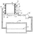
- FIG. 6is a schematic view of one possible arrangement of pump and pressurized coolant source for use with the present invention.
- a heat pipe with chilled liquid condenser system 1 for use in cooling semiconductors devices F during burn-in testingincludes a heat pipe 5 and a heat exchanger coil 7 .
- heat pipe 5comprises of a vessel 10 , a wick 15 , and a working fluid 20 .
- Vessel 10includes an outer surface 21 , a first end 22 , a second end 24 , and a central passageway 26 that is defined by the interior surface 28 of vessel 10 .
- Vessel 10also includes a thermal interface base 27 that is fixedly and hermetically attached to second end 24 .
- a thermally conductive materiale.g., copper or its alloys, monel, or the like
- Central passageway 26defines a vapor space within vessel 10 .
- Vessel 10is often about 10 mm in diameter and about 12 mm in height.
- Wick 15is disposed upon interior surface 28 of vessel 10 , and may comprise adjacent layers of screening or a sintered powder structure with interstices between the particles of powder.
- wick 15may comprise sintered copper powder, sintered aluminum-silicon-carbide (AlSiC) or copper-silicon-carbide (CuSiC) having an average thickness of about 0.1 mm to 1.0 mm.
- the working fluid(not shown) may comprise any of the well known two-phase vaporizable liquids, e.g., water, alcohol, freon, etc.
- Heat exchanger coil 7comprises an elongate hollow tube 35 having a central passageway 37 of stainless steel, copper or its alloys, or the like highly thermally conductive material.
- Tube 35includes a first conduit end 40 and a second conduit end 42 that are in fluid communication with one another through central passageway 37 .
- Heat exchanger coil 7is coiled around the outer surface 21 of vessel 10 such that a first set of interior coils 45 are formed adjacent to outer surface 21 ( FIG. 3 ). Interior coils 45 are often brazed to outer surface 21 to increase their thermal contact with vessel 10 .
- a second set of coils 47are positioned in overlying relation to first set of interior coils 45 .
- First conduit end 40 and second conduit end 42are arranged in flow communication with a source 50 of chilled coolant 51 and a pump 52 so as to circulate coolant 51 through both first set of interior coils 45 and second set of coils 47 ( FIG. 4 ).
- base 27 of heat pipe 5is exposed to one or more heat sources, e.g., semiconductor chip F, while at the same time first end 22 of heat pipe 5 is thermally engaged with heat exchanger coil 7 , which is at a substantially lower temperature than semiconductor chip F.
- Heatis absorbed from semiconductor chip F by evaporation of liquid-phase working fluid 20 to vapor phase inside heat pipe 5 at second end 24 .
- Working fluid 20 in vapor phase with its absorbed heat loadis thermodynamically driven first end 22 of heat pipe 5 due to a pressure difference created between second end 24 and first end 22 by the heat generated by semiconductor chip F ( FIG. 5 ).
Landscapes
- Engineering & Computer Science (AREA)
- General Engineering & Computer Science (AREA)
- Physics & Mathematics (AREA)
- Mechanical Engineering (AREA)
- Thermal Sciences (AREA)
- Life Sciences & Earth Sciences (AREA)
- Sustainable Development (AREA)
- Environmental & Geological Engineering (AREA)
- Microelectronics & Electronic Packaging (AREA)
- Computer Hardware Design (AREA)
- General Physics & Mathematics (AREA)
- Health & Medical Sciences (AREA)
- Toxicology (AREA)
- Testing Of Individual Semiconductor Devices (AREA)
Abstract
Description
Claims (3)
Priority Applications (1)
| Application Number | Priority Date | Filing Date | Title |
|---|---|---|---|
| US10/929,869US7129731B2 (en) | 2003-09-02 | 2004-08-30 | Heat pipe with chilled liquid condenser system for burn-in testing |
Applications Claiming Priority (3)
| Application Number | Priority Date | Filing Date | Title |
|---|---|---|---|
| US49948303P | 2003-09-02 | 2003-09-02 | |
| US50212503P | 2003-09-11 | 2003-09-11 | |
| US10/929,869US7129731B2 (en) | 2003-09-02 | 2004-08-30 | Heat pipe with chilled liquid condenser system for burn-in testing |
Publications (2)
| Publication Number | Publication Date |
|---|---|
| US20050068734A1 US20050068734A1 (en) | 2005-03-31 |
| US7129731B2true US7129731B2 (en) | 2006-10-31 |
Family
ID=34381955
Family Applications (1)
| Application Number | Title | Priority Date | Filing Date |
|---|---|---|---|
| US10/929,869Expired - Fee RelatedUS7129731B2 (en) | 2003-09-02 | 2004-08-30 | Heat pipe with chilled liquid condenser system for burn-in testing |
Country Status (1)
| Country | Link |
|---|---|
| US (1) | US7129731B2 (en) |
Cited By (3)
| Publication number | Priority date | Publication date | Assignee | Title |
|---|---|---|---|---|
| CN101754658A (en)* | 2008-12-11 | 2010-06-23 | 富准精密工业(深圳)有限公司 | Radiating device |
| US20140077829A1 (en)* | 2012-09-17 | 2014-03-20 | Samsung Electronics Co., Ltd | Test handler that rapidly transforms temperature and method of testing semiconductor device using the same |
| US12255123B2 (en) | 2015-09-30 | 2025-03-18 | Microfabrica Inc. | Micro heat transfer arrays, micro cold plates, and thermal management systems for semiconductor devices, and methods for using and making such arrays, plates, and systems |
Families Citing this family (8)
| Publication number | Priority date | Publication date | Assignee | Title |
|---|---|---|---|---|
| CN100516853C (en)* | 2005-08-12 | 2009-07-22 | 鸿富锦精密工业(深圳)有限公司 | Heat pipe performance measuring device |
| US20100108297A1 (en)* | 2007-04-28 | 2010-05-06 | Jen-Shyan Chen | Heat Pipe and Making Method Thereof |
| US20140223957A1 (en)* | 2011-10-27 | 2014-08-14 | Zhiming Wang | Compressor-free refrigeration system powered by heat source |
| CN103339451A (en)* | 2011-10-27 | 2013-10-02 | 王智鸣 | Compressor-free cooling system powered by heat source |
| CN104422017A (en)* | 2013-08-19 | 2015-03-18 | 江苏香江科技股份有限公司 | Active heat pipe back plate cooling system |
| CN112432535B (en)* | 2020-11-27 | 2022-08-30 | 巨野百林化学有限公司 | Unit type heat exchange device for chemical production |
| CN116520134B (en)* | 2022-11-09 | 2024-01-09 | 珠海精实测控技术股份有限公司 | Temperature control testing system |
| CN117848125B (en)* | 2024-01-09 | 2024-07-16 | 无锡巨日装备科技有限公司 | Gravity type liquid heat conduction and dissipation integrated device |
Citations (52)
| Publication number | Priority date | Publication date | Assignee | Title |
|---|---|---|---|---|
| US2137044A (en)* | 1937-04-07 | 1938-11-15 | Westinghouse Electric & Mfg Co | Cooling jacket fabrication |
| US4037830A (en) | 1976-09-07 | 1977-07-26 | International Business Machines Corporation | Wafer handler |
| US4213698A (en) | 1978-12-01 | 1980-07-22 | Bell Telephone Laboratories, Incorporated | Apparatus and method for holding and planarizing thin workpieces |
| USRE31053E (en) | 1978-01-23 | 1982-10-12 | Bell Telephone Laboratories, Incorporated | Apparatus and method for holding and planarizing thin workpieces |
| US4551192A (en) | 1983-06-30 | 1985-11-05 | International Business Machines Corporation | Electrostatic or vacuum pinchuck formed with microcircuit lithography |
| US4609037A (en) | 1985-10-09 | 1986-09-02 | Tencor Instruments | Apparatus for heating and cooling articles |
| US4633371A (en)* | 1984-09-17 | 1986-12-30 | Amdahl Corporation | Heat pipe heat exchanger for large scale integrated circuits |
| US4784213A (en) | 1986-04-08 | 1988-11-15 | Temptronic Corporation | Mixing valve air source |
| US5001423A (en) | 1990-01-24 | 1991-03-19 | International Business Machines Corporation | Dry interface thermal chuck temperature control system for semiconductor wafer testing |
| US5084671A (en) | 1987-09-02 | 1992-01-28 | Tokyo Electron Limited | Electric probing-test machine having a cooling system |
| US5382311A (en) | 1992-12-17 | 1995-01-17 | Tokyo Electron Limited | Stage having electrostatic chuck and plasma processing apparatus using same |
| US5383971A (en) | 1990-10-12 | 1995-01-24 | Genus, Inc. | Differential pressure CVD chuck |
| US5412535A (en)* | 1993-08-24 | 1995-05-02 | Convex Computer Corporation | Apparatus and method for cooling electronic devices |
| US5413167A (en)* | 1990-07-30 | 1995-05-09 | Canon Kabushiki Kaisha | Wafer cooling device |
| US5435379A (en) | 1992-08-14 | 1995-07-25 | Texas Instruments Incorporated | Method and apparatus for low-temperature semiconductor processing |
| US5458687A (en) | 1992-11-20 | 1995-10-17 | Hitachi, Ltd. | Method of and apparatus for securing and cooling/heating a wafer |
| US5460684A (en) | 1992-12-04 | 1995-10-24 | Tokyo Electron Limited | Stage having electrostatic chuck and plasma processing apparatus using same |
| US5474877A (en) | 1994-02-24 | 1995-12-12 | Nec Corporation | Method for developing a resist pattern |
| US5478609A (en) | 1992-07-23 | 1995-12-26 | Canon Kabushiki Kaisha | Substrate heating mechanism |
| US5534073A (en) | 1992-09-07 | 1996-07-09 | Mitsubishi Denki Kabushiki Kaisha | Semiconductor producing apparatus comprising wafer vacuum chucking device |
| US5582242A (en)* | 1992-05-15 | 1996-12-10 | Digital Equipment Corporation | Thermosiphon for cooling a high power die |
| US5588827A (en) | 1993-12-17 | 1996-12-31 | Brooks Automation Inc. | Passive gas substrate thermal conditioning apparatus and method |
| US5610529A (en) | 1995-04-28 | 1997-03-11 | Cascade Microtech, Inc. | Probe station having conductive coating added to thermal chuck insulator |
| US5632158A (en)* | 1995-03-20 | 1997-05-27 | Calsonic Corporation | Electronic component cooling unit |
| US5663653A (en) | 1992-06-11 | 1997-09-02 | Cascade Microtech, Inc. | Wafer probe station for low-current measurements |
| US5721090A (en) | 1994-09-22 | 1998-02-24 | Tokyo Electron Limited | Method of etching a substrate |
| US5730803A (en) | 1996-02-23 | 1998-03-24 | Applied Materials, Inc. | Apparatus and method for transferring heat from a hot electrostatic chuck to an underlying cold body |
| US5738165A (en) | 1993-05-07 | 1998-04-14 | Nikon Corporation | Substrate holding apparatus |
| US5762714A (en) | 1994-10-18 | 1998-06-09 | Applied Materials, Inc. | Plasma guard for chamber equipped with electrostatic chuck |
| US5820723A (en) | 1996-06-05 | 1998-10-13 | Lam Research Corporation | Universal vacuum chamber including equipment modules such as a plasma generating source, vacuum pumping arrangement and/or cantilevered substrate support |
| US5830808A (en) | 1993-10-29 | 1998-11-03 | Applied Materials, Inc. | Plasma reactor with magnet for protecting an electroacoustic chuck from the plasma |
| US5885353A (en) | 1996-06-21 | 1999-03-23 | Micron Technology, Inc. | Thermal conditioning apparatus |
| US5894887A (en)* | 1995-11-30 | 1999-04-20 | Applied Materials, Inc. | Ceramic dome temperature control using heat pipe structure and method |
| US5904776A (en) | 1996-04-26 | 1999-05-18 | Applied Materials, Inc. | Conduits for flow of heat transfer fluid to the surface of an electrostatic chuck |
| US5904779A (en) | 1996-12-19 | 1999-05-18 | Lam Research Corporation | Wafer electrical discharge control by wafer lifter system |
| US5944093A (en)* | 1997-12-30 | 1999-08-31 | Intel Corporation | Pickup chuck with an integral heat pipe |
| US5958140A (en) | 1995-07-27 | 1999-09-28 | Tokyo Electron Limited | One-by-one type heat-processing apparatus |
| US6032724A (en) | 1996-10-29 | 2000-03-07 | Tokyo Electron Limited | Temperature control apparatus for sample susceptor |
| US6037793A (en) | 1997-01-30 | 2000-03-14 | Tokyo Electron Limited | Inspecting method and apparatus for semiconductor integrated circuit |
| US6073681A (en) | 1997-12-31 | 2000-06-13 | Temptronic Corporation | Workpiece chuck |
| US6245202B1 (en) | 1996-04-12 | 2001-06-12 | Hitachi, Ltd. | Plasma treatment device |
| US6313649B2 (en) | 1992-06-11 | 2001-11-06 | Cascade Microtech, Inc. | Wafer probe station having environment control enclosure |
| US6394797B1 (en) | 1997-04-02 | 2002-05-28 | Hitachi, Ltd. | Substrate temperature control system and method for controlling temperature of substrate |
| US6471913B1 (en) | 2000-02-09 | 2002-10-29 | Semitool, Inc. | Method and apparatus for processing a microelectronic workpiece including an apparatus and method for executing a processing step at an elevated temperature |
| US20030066628A1 (en)* | 2001-10-10 | 2003-04-10 | Fujikura Ltd. | Tower type finned heat pipe type heat sink |
| US6583638B2 (en) | 1999-01-26 | 2003-06-24 | Trio-Tech International | Temperature-controlled semiconductor wafer chuck system |
| US6700641B2 (en)* | 1997-08-29 | 2004-03-02 | Nikon Corporation | Temperature control method and exposure apparatus thereby |
| US6725909B1 (en)* | 2003-01-06 | 2004-04-27 | Chin-Kuang Luo | Heat-dissipating device and method for fabricating the same |
| US6771086B2 (en) | 2002-02-19 | 2004-08-03 | Lucas/Signatone Corporation | Semiconductor wafer electrical testing with a mobile chiller plate for rapid and precise test temperature control |
| US6793009B1 (en)* | 2003-06-10 | 2004-09-21 | Thermal Corp. | CTE-matched heat pipe |
| US6867974B2 (en)* | 2002-11-25 | 2005-03-15 | Chin-Kuang Luo | Heat-dissipating device |
| US6938680B2 (en)* | 2003-07-14 | 2005-09-06 | Thermal Corp. | Tower heat sink with sintered grooved wick |
- 2004
- 2004-08-30USUS10/929,869patent/US7129731B2/ennot_activeExpired - Fee Related
Patent Citations (52)
| Publication number | Priority date | Publication date | Assignee | Title |
|---|---|---|---|---|
| US2137044A (en)* | 1937-04-07 | 1938-11-15 | Westinghouse Electric & Mfg Co | Cooling jacket fabrication |
| US4037830A (en) | 1976-09-07 | 1977-07-26 | International Business Machines Corporation | Wafer handler |
| USRE31053E (en) | 1978-01-23 | 1982-10-12 | Bell Telephone Laboratories, Incorporated | Apparatus and method for holding and planarizing thin workpieces |
| US4213698A (en) | 1978-12-01 | 1980-07-22 | Bell Telephone Laboratories, Incorporated | Apparatus and method for holding and planarizing thin workpieces |
| US4551192A (en) | 1983-06-30 | 1985-11-05 | International Business Machines Corporation | Electrostatic or vacuum pinchuck formed with microcircuit lithography |
| US4633371A (en)* | 1984-09-17 | 1986-12-30 | Amdahl Corporation | Heat pipe heat exchanger for large scale integrated circuits |
| US4609037A (en) | 1985-10-09 | 1986-09-02 | Tencor Instruments | Apparatus for heating and cooling articles |
| US4784213A (en) | 1986-04-08 | 1988-11-15 | Temptronic Corporation | Mixing valve air source |
| US5084671A (en) | 1987-09-02 | 1992-01-28 | Tokyo Electron Limited | Electric probing-test machine having a cooling system |
| US5001423A (en) | 1990-01-24 | 1991-03-19 | International Business Machines Corporation | Dry interface thermal chuck temperature control system for semiconductor wafer testing |
| US5413167A (en)* | 1990-07-30 | 1995-05-09 | Canon Kabushiki Kaisha | Wafer cooling device |
| US5383971A (en) | 1990-10-12 | 1995-01-24 | Genus, Inc. | Differential pressure CVD chuck |
| US5582242A (en)* | 1992-05-15 | 1996-12-10 | Digital Equipment Corporation | Thermosiphon for cooling a high power die |
| US5663653A (en) | 1992-06-11 | 1997-09-02 | Cascade Microtech, Inc. | Wafer probe station for low-current measurements |
| US6313649B2 (en) | 1992-06-11 | 2001-11-06 | Cascade Microtech, Inc. | Wafer probe station having environment control enclosure |
| US5478609A (en) | 1992-07-23 | 1995-12-26 | Canon Kabushiki Kaisha | Substrate heating mechanism |
| US5435379A (en) | 1992-08-14 | 1995-07-25 | Texas Instruments Incorporated | Method and apparatus for low-temperature semiconductor processing |
| US5534073A (en) | 1992-09-07 | 1996-07-09 | Mitsubishi Denki Kabushiki Kaisha | Semiconductor producing apparatus comprising wafer vacuum chucking device |
| US5458687A (en) | 1992-11-20 | 1995-10-17 | Hitachi, Ltd. | Method of and apparatus for securing and cooling/heating a wafer |
| US5460684A (en) | 1992-12-04 | 1995-10-24 | Tokyo Electron Limited | Stage having electrostatic chuck and plasma processing apparatus using same |
| US5382311A (en) | 1992-12-17 | 1995-01-17 | Tokyo Electron Limited | Stage having electrostatic chuck and plasma processing apparatus using same |
| US5738165A (en) | 1993-05-07 | 1998-04-14 | Nikon Corporation | Substrate holding apparatus |
| US5412535A (en)* | 1993-08-24 | 1995-05-02 | Convex Computer Corporation | Apparatus and method for cooling electronic devices |
| US5830808A (en) | 1993-10-29 | 1998-11-03 | Applied Materials, Inc. | Plasma reactor with magnet for protecting an electroacoustic chuck from the plasma |
| US5588827A (en) | 1993-12-17 | 1996-12-31 | Brooks Automation Inc. | Passive gas substrate thermal conditioning apparatus and method |
| US5474877A (en) | 1994-02-24 | 1995-12-12 | Nec Corporation | Method for developing a resist pattern |
| US5721090A (en) | 1994-09-22 | 1998-02-24 | Tokyo Electron Limited | Method of etching a substrate |
| US5762714A (en) | 1994-10-18 | 1998-06-09 | Applied Materials, Inc. | Plasma guard for chamber equipped with electrostatic chuck |
| US5632158A (en)* | 1995-03-20 | 1997-05-27 | Calsonic Corporation | Electronic component cooling unit |
| US5610529A (en) | 1995-04-28 | 1997-03-11 | Cascade Microtech, Inc. | Probe station having conductive coating added to thermal chuck insulator |
| US5958140A (en) | 1995-07-27 | 1999-09-28 | Tokyo Electron Limited | One-by-one type heat-processing apparatus |
| US5894887A (en)* | 1995-11-30 | 1999-04-20 | Applied Materials, Inc. | Ceramic dome temperature control using heat pipe structure and method |
| US5730803A (en) | 1996-02-23 | 1998-03-24 | Applied Materials, Inc. | Apparatus and method for transferring heat from a hot electrostatic chuck to an underlying cold body |
| US6245202B1 (en) | 1996-04-12 | 2001-06-12 | Hitachi, Ltd. | Plasma treatment device |
| US5904776A (en) | 1996-04-26 | 1999-05-18 | Applied Materials, Inc. | Conduits for flow of heat transfer fluid to the surface of an electrostatic chuck |
| US5820723A (en) | 1996-06-05 | 1998-10-13 | Lam Research Corporation | Universal vacuum chamber including equipment modules such as a plasma generating source, vacuum pumping arrangement and/or cantilevered substrate support |
| US5885353A (en) | 1996-06-21 | 1999-03-23 | Micron Technology, Inc. | Thermal conditioning apparatus |
| US6032724A (en) | 1996-10-29 | 2000-03-07 | Tokyo Electron Limited | Temperature control apparatus for sample susceptor |
| US5904779A (en) | 1996-12-19 | 1999-05-18 | Lam Research Corporation | Wafer electrical discharge control by wafer lifter system |
| US6037793A (en) | 1997-01-30 | 2000-03-14 | Tokyo Electron Limited | Inspecting method and apparatus for semiconductor integrated circuit |
| US6394797B1 (en) | 1997-04-02 | 2002-05-28 | Hitachi, Ltd. | Substrate temperature control system and method for controlling temperature of substrate |
| US6700641B2 (en)* | 1997-08-29 | 2004-03-02 | Nikon Corporation | Temperature control method and exposure apparatus thereby |
| US5944093A (en)* | 1997-12-30 | 1999-08-31 | Intel Corporation | Pickup chuck with an integral heat pipe |
| US6073681A (en) | 1997-12-31 | 2000-06-13 | Temptronic Corporation | Workpiece chuck |
| US6583638B2 (en) | 1999-01-26 | 2003-06-24 | Trio-Tech International | Temperature-controlled semiconductor wafer chuck system |
| US6471913B1 (en) | 2000-02-09 | 2002-10-29 | Semitool, Inc. | Method and apparatus for processing a microelectronic workpiece including an apparatus and method for executing a processing step at an elevated temperature |
| US20030066628A1 (en)* | 2001-10-10 | 2003-04-10 | Fujikura Ltd. | Tower type finned heat pipe type heat sink |
| US6771086B2 (en) | 2002-02-19 | 2004-08-03 | Lucas/Signatone Corporation | Semiconductor wafer electrical testing with a mobile chiller plate for rapid and precise test temperature control |
| US6867974B2 (en)* | 2002-11-25 | 2005-03-15 | Chin-Kuang Luo | Heat-dissipating device |
| US6725909B1 (en)* | 2003-01-06 | 2004-04-27 | Chin-Kuang Luo | Heat-dissipating device and method for fabricating the same |
| US6793009B1 (en)* | 2003-06-10 | 2004-09-21 | Thermal Corp. | CTE-matched heat pipe |
| US6938680B2 (en)* | 2003-07-14 | 2005-09-06 | Thermal Corp. | Tower heat sink with sintered grooved wick |
Cited By (5)
| Publication number | Priority date | Publication date | Assignee | Title |
|---|---|---|---|---|
| CN101754658A (en)* | 2008-12-11 | 2010-06-23 | 富准精密工业(深圳)有限公司 | Radiating device |
| CN101754658B (en)* | 2008-12-11 | 2013-06-05 | 富准精密工业(深圳)有限公司 | Radiating device |
| US20140077829A1 (en)* | 2012-09-17 | 2014-03-20 | Samsung Electronics Co., Ltd | Test handler that rapidly transforms temperature and method of testing semiconductor device using the same |
| US9207272B2 (en)* | 2012-09-17 | 2015-12-08 | Samsung Eletronics Co., Ltd. | Test handler that rapidly transforms temperature and method of testing semiconductor device using the same |
| US12255123B2 (en) | 2015-09-30 | 2025-03-18 | Microfabrica Inc. | Micro heat transfer arrays, micro cold plates, and thermal management systems for semiconductor devices, and methods for using and making such arrays, plates, and systems |
Also Published As
| Publication number | Publication date |
|---|---|
| US20050068734A1 (en) | 2005-03-31 |
Similar Documents
| Publication | Publication Date | Title |
|---|---|---|
| US3710251A (en) | Microelectric heat exchanger pedestal | |
| US7129731B2 (en) | Heat pipe with chilled liquid condenser system for burn-in testing | |
| JP6966597B2 (en) | Cryogenic cooling system | |
| US7143818B2 (en) | Heat pipe evaporator with porous valve | |
| TWI251067B (en) | Spray cooling and transparent cooling plate thermal management system | |
| US6505478B1 (en) | Heat exchanger having sloped deflection surface for directing refrigerant | |
| EP3523582B1 (en) | Passive flow direction biasing of cryogenic thermosiphon | |
| US8066429B2 (en) | System and method for thermal analysis using variable thermal resistance | |
| Hou et al. | Microchannel thermal management system with two-phase flow for power electronics over 500 W/cm 2 heat dissipation | |
| JP4431793B2 (en) | Cryostat | |
| US20020003037A1 (en) | Temperature-controlled chuck with recovery of circulating temperature control fluid | |
| US7667476B2 (en) | Measuring module for rapid measurement of electrical, electronic and mechanical components at cryogenic temperatures and measuring device having such a module | |
| KR20140113881A (en) | Direct injection phase change temperature control system | |
| US20170284725A1 (en) | Cryostat with a first and a second helium tank, which are separated from one another in a liquid-tight manner at least in a lower part | |
| Hou et al. | Experimental evaluation of a compact two-phase cooling system for high heat flux electronic packages | |
| US20050067146A1 (en) | Two phase cooling system method for burn-in testing | |
| US20080156996A1 (en) | Indirect Method and Apparatus for Cooling a Silicon Drift Detector | |
| US20050067147A1 (en) | Loop thermosyphon for cooling semiconductors during burn-in testing | |
| US11530845B2 (en) | Cryogenic apparatus | |
| JP4169511B2 (en) | Sample temperature controller | |
| BRPI0315812B1 (en) | thermodynamic system and method of using the thermodynamic system | |
| US20120216559A1 (en) | Mounting device | |
| JP4759551B2 (en) | Flow cooling magnet system | |
| Vasiliev Jr et al. | Heat transfer with propane evaporation from a porous wick of heat pipe | |
| Khrustalev | Cryogenic loop heat pipes as flexible thermal links for cryocoolers |
Legal Events
| Date | Code | Title | Description |
|---|---|---|---|
| AS | Assignment | Owner name:THERMAL CORP., DELAWARE Free format text:ASSIGNMENT OF ASSIGNORS INTEREST;ASSIGNORS:THAYER, JOHN GILBERT;ERNST, DONALD M.;REEL/FRAME:015437/0892;SIGNING DATES FROM 20040827 TO 20041011 | |
| FEPP | Fee payment procedure | Free format text:PAYOR NUMBER ASSIGNED (ORIGINAL EVENT CODE: ASPN); ENTITY STATUS OF PATENT OWNER: LARGE ENTITY | |
| AS | Assignment | Owner name:NATIONAL PENN BANK, PENNSYLVANIA Free format text:SECURITY AGREEMENT;ASSIGNORS:THERMAL CORP.;FSBO VENTURE ACQUISITIONS, INC.;REEL/FRAME:021398/0300 Effective date:20080430 Owner name:NATIONAL PENN BANK,PENNSYLVANIA Free format text:SECURITY AGREEMENT;ASSIGNORS:THERMAL CORP.;FSBO VENTURE ACQUISITIONS, INC.;REEL/FRAME:021398/0300 Effective date:20080430 | |
| REMI | Maintenance fee reminder mailed | ||
| LAPS | Lapse for failure to pay maintenance fees | ||
| STCH | Information on status: patent discontinuation | Free format text:PATENT EXPIRED DUE TO NONPAYMENT OF MAINTENANCE FEES UNDER 37 CFR 1.362 | |
| FP | Lapsed due to failure to pay maintenance fee | Effective date:20101031 | |
| AS | Assignment | Owner name:SOVEREIGN BANK, PENNSYLVANIA Free format text:SECURITY AGREEMENT;ASSIGNORS:THERMACORE, INC.;THERMAL CORP.;REEL/FRAME:026039/0865 Effective date:20101230 | |
| AS | Assignment | Owner name:THERMACORE, INC., PENNSYLVANIA Free format text:RELEASE OF SECURITY INTEREST RECORDED AT REEL/FRAME 026039/0865;ASSIGNOR:SANTANDER BANK, N.A. F/K/A SOVEREIGN BANK;REEL/FRAME:040508/0649 Effective date:20161013 Owner name:THERMACORE, INC. F/K/A FSBO VENTURE ACQUISITIONS, Free format text:RELEASE OF SECURITY INTEREST RECORDED AT REEL/FRAME 021398/0300;ASSIGNOR:NATIONAL PENN BANK;REEL/FRAME:040508/0620 Effective date:20101230 Owner name:THERMAL CORP., NEW HAMPSHIRE Free format text:RELEASE OF SECURITY INTEREST RECORDED AT REEL/FRAME 021398/0300;ASSIGNOR:NATIONAL PENN BANK;REEL/FRAME:040508/0620 Effective date:20101230 Owner name:THERMAL CORP., NEW HAMPSHIRE Free format text:RELEASE OF SECURITY INTEREST RECORDED AT REEL/FRAME 026039/0865;ASSIGNOR:SANTANDER BANK, N.A. F/K/A SOVEREIGN BANK;REEL/FRAME:040508/0649 Effective date:20161013 |