US7128868B2 - Balloon wing forming apparatus and method - Google Patents
Balloon wing forming apparatus and methodDownload PDFInfo
- Publication number
- US7128868B2 US7128868B2US10/340,819US34081903AUS7128868B2US 7128868 B2US7128868 B2US 7128868B2US 34081903 AUS34081903 AUS 34081903AUS 7128868 B2US7128868 B2US 7128868B2
- Authority
- US
- United States
- Prior art keywords
- balloon
- medical balloon
- wings
- members
- blades
- Prior art date
- Legal status (The legal status is an assumption and is not a legal conclusion. Google has not performed a legal analysis and makes no representation as to the accuracy of the status listed.)
- Expired - Lifetime, expires
Links
Images


Classifications
- A—HUMAN NECESSITIES
- A61—MEDICAL OR VETERINARY SCIENCE; HYGIENE
- A61M—DEVICES FOR INTRODUCING MEDIA INTO, OR ONTO, THE BODY; DEVICES FOR TRANSDUCING BODY MEDIA OR FOR TAKING MEDIA FROM THE BODY; DEVICES FOR PRODUCING OR ENDING SLEEP OR STUPOR
- A61M25/00—Catheters; Hollow probes
- A61M25/10—Balloon catheters
- A61M25/1027—Making of balloon catheters
- A61M25/1038—Wrapping or folding devices for use with balloon catheters
Definitions
- Medical balloonsare used in the body in a variety of applications including as dilatation devices for compressing plaque and for expanding prosthetic devices such as stents at a desired location in a bodily vessel. Because it is typically necessary for the balloon to traverse a tortuous anatomy as it is being delivered to the desired location in the bodily vessel, it is desirable for the balloon to assume as low a profile as possible.
- One way to achieve a low profileis by folding the balloon to form a number of wings.
- Some examples of methods of forming wings on a balloonare described in U.S. Pat. Nos. 5,147,302 and 5,350,361.
- a common method employed to form wings on a balloonis to partially inflate a balloon and then impart an inward radial force about the periphery of the balloon using a plurality of members or “blades” which are distributed about the periphery of the balloon. As the blades move radially inward, wings are formed in the balloon.
- a goal of the present inventionto provide a wing forming method and apparatus that reduces the friction between the balloon and blades, provides for improved ability to produce wings having uniform lengths and/or provides for improved crease formation.
- the present inventionis directed to a variety of embodiments.
- the inventionis directed to a method for forming balloon wings, wherein the method employs vibrational energy to aid in wing formation.
- the inventionis directed to a balloon wing forming apparatus.
- One or more portions of the apparatusis equipped with one or more transducers that may be excited to impart a vibration to at least a portion of the apparatus.
- the vibrationhas an ultrasonic frequency.
- the apparatusemploys a plurality of members or blades which are constructed and arranged to push radially inward against the balloon to form the wings.
- the apparatusemploys a plurality of inflatable members which when inflated are constructed and arranged to push radially inward against the balloon to form the wings.
- application of vibratory energy to the wing forming apparatusmay aid in forming balloon wings that are substantially uniform in length.
- application of vibrations to the wing forming apparatusmay aid in providing improved creasing of the balloon wings in the body region of the balloon and/or the cone regions of the balloon.
- FIG. 1is a cross-sectional view of a balloon formed in accordance with an embodiment of the invention.
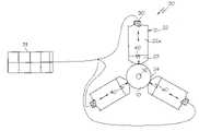
- FIG. 2is a cross-sectional view of an embodiment of the invention.
- FIG. 3is a cross-sectional view of the embodiment illustrated in FIG. 2 shown with a balloon positioned therein.
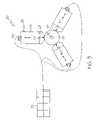
- FIG. 4is a cross-sectional view of the apparatus illustrated in FIG. 3 shown during the wing formation process.
- FIG. 5is a cross-sectional view of the apparatus illustrated in FIG. 4 shown during the wing formation process.
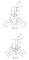
- FIG. 6is a perspective view of an embodiment of the invention shown with a balloon positioned therein.
- FIG. 7is a perspective view of the apparatus illustrated in FIG. 6 shown during the wing formation process.
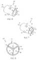
- FIG. 8is a cross-sectional view of an embodiment of the invention shown during the wing formation process.
- FIG. 9is a perspective view of a balloon formed in accordance with an embodiment of the invention.
- the present inventionis embodied in a variety of forms.
- the inventionis directed to one or more methods of forming at least one fold or wing 12 in a balloon catheter 10 , such as is shown in FIG. 1 , wherein the methods utilize vibrations in the wing formation process.
- a method of forming balloon wingsis accomplished through the use of a balloon folding apparatus, indicated generally at 20 in FIG. 2 .
- the apparatus 20comprises a plurality of moveable members 22 .
- members 22are characterized as moveable blades 22 a
- members 22are inflatable members 22 b .
- Members 22are uniformly disposed about a receiving area 24 .
- blades 22 aare constructed and arranged to be moved in a radial direction into the receiving area 24 as well as out of the receiving area 24 .
- a catheter balloon 10is positioned within receiving area 24 when the blades are in the open position such as is shown in FIG. 3 .
- the balloon 10is partially inflated under a pressure of about 20–40 p.s.i. In some embodiments the balloon is inflated to about 30 p.s.i.
- the blades 22 aare moved radially inward to push against the outside surface 14 of the balloon 10 . As the blades 22 a push against the balloon catheter 10 , portions of the balloon are forced radially outward away from the catheter shaft 16 to form wings 12 . When the blades 22 a are in their fully closed position about the catheter shaft 16 , such as is shown in FIG. 5 , the wings 12 are fully formed between adjacent blades 22 a.
- the folding apparatus 20includes one or more transducers 30 which are functionally engaged to one or more of the members 22 and/or other portions of the apparatus 20 , such as shown in FIGS. 2–3 and 6 – 8 .
- Transducers 30transmit vibratory energy in order to impart vibrations to the apparatus 20 .
- the vibrations produced by the transducers 30may be of any frequency, but in at least one embodiment the vibrations are in the ultrasonic range.
- Ultrasonic vibratory energymay provide a uniform or non-uniform vibration to a selected portion of a member 22 .
- the transducers 30may provide ultrasonic energy in a frequency that can range from less than about 1,000 kiloHertz.
- transducers 30may be piezo-electric transducers that are engaged to an ultrasonic generator 31 such as is shown in FIGS. 2–3 .
- the generator 31provides electrical energy to the transducers 30 .
- the transducers 30then convert the electrical energy to mechanical energy in the form of vibrations.
- the transducers 30 and/or another component of the apparatus 20may include a heating element 33 which heats one or more portions of the members 22 .
- the transducers 30may emit vibratory energy which not only imparts vibrations to at least a portion of the members 22 and balloon 10 , but which also acts to heat at least a portion of the members 22 and balloon 10 .
- heating the balloon material during the wing forming processwill aid in forming the wings 12 by softening the balloon material to allow for an improved creased fold.
- the vibratory energyis communicated to the balloon 10 during the wing forming process. Vibration of the members 22 and balloon 10 results in a reduced frictional interface between the members 22 and balloon 10 .
- balloon contacting portions 23 of the blades 22 ais at least partially constructed of a relatively soft material such as Silicone, natural or synthetic polymers, etc.
- the remaining portion of each blade 22 amay be constructed of metal and/or other materials.
- the application of vibratory energy to the balloon 10will aid in providing a balloon that has wings of substantially the same uniform length, such as is shown in FIG. 1 .
- the members 22 of the apparatus 20are characterized as inflatable members 22 b rather than moveable blades 22 a , such as are shown in FIGS. 2–5 .
- Inflatable members 22 bare inflatable from an uninflated state shown in FIG. 6 to a fully inflated state shown in FIG. 7 .
- the members 22 bincrease in diameter thereby directing an inward acting force against the balloon 10 that is positioned within the receiving region 24 .
- the members 22 bare fully inflated the wings 12 are sandwiched between the adjacent fully inflated members 22 b .
- Transducers 30may be engaged to any region of the members 22 b .
- the members 22 bmay be disposed about the transducer 30 such as is shown in FIG. 8 .
- the vibratory energy emitted from the transducers 30is passed through an inflation media 44 to the members 22 b and eventually to the balloon 10 .
- the application of vibratory energy to the members 22 and balloon 10also improves the profile and crease characteristics of the wings 12 .
- the wings 12are positioned with in the space 25 between adjacent members 22 .
- the members 22push inward against segments 40 of the balloon 10 causing the material of the wings 12 to be pushed outward into the spaces 25 between the members 22 .
- each wingis compressed between adjacent members 22 to form a crease 42 along their respective outside edges.
- application of vibrations to the members 22 and wings 12helps to provide each wing with a well defined crease 42 that extends through the length of the entire balloon 10 such as is shown in FIG. 9 .
- vibrating the balloon 10 when the apparatus is closedassists in forming a crease through the body 50 of the balloon as well as in the adjacent cone regions 52 and 54 .
- Providing a crease 42 that extends through all portions of the balloonaids in forming flatter more easily folded wings 12 .
- cone regions 52 and 54with improved creasing, the folded balloon profile over the cones may be decreased. This reduction reduces the risk of damaging the balloon while positioning a stent onto the balloon. The reduction in cone profile also allows a catheter equipped with such a balloon to cross lesion sights with greater ease. Finally, by providing a balloon with improved body and cone creasing the forces necessary to crimp a stent or other medical device to the balloon may be reduced.
- any dependent claim which followsshould be taken as alternatively written in a multiple dependent form from all prior claims which possess all antecedents referenced in such dependent claim if such multiple dependent format is an accepted format within the jurisdiction (e.g. each claim depending directly from claim 1 should be alternatively taken as depending from all previous claims).
- each claim depending directly from claim 1should be alternatively taken as depending from all previous claims.
- the following dependent claimsshould each be also taken as alternatively written in each singly dependent claim format which creates a dependency from a prior antecedent-possessing claim other than the specific claim listed in such dependent claim below.
Landscapes
- Health & Medical Sciences (AREA)
- Life Sciences & Earth Sciences (AREA)
- Heart & Thoracic Surgery (AREA)
- Engineering & Computer Science (AREA)
- Biophysics (AREA)
- Pulmonology (AREA)
- Child & Adolescent Psychology (AREA)
- Anesthesiology (AREA)
- Biomedical Technology (AREA)
- Hematology (AREA)
- Animal Behavior & Ethology (AREA)
- General Health & Medical Sciences (AREA)
- Public Health (AREA)
- Veterinary Medicine (AREA)
- Media Introduction/Drainage Providing Device (AREA)
Abstract
Description
Claims (10)
Priority Applications (1)
| Application Number | Priority Date | Filing Date | Title |
|---|---|---|---|
| US10/340,819US7128868B2 (en) | 2003-01-10 | 2003-01-10 | Balloon wing forming apparatus and method |
Applications Claiming Priority (1)
| Application Number | Priority Date | Filing Date | Title |
|---|---|---|---|
| US10/340,819US7128868B2 (en) | 2003-01-10 | 2003-01-10 | Balloon wing forming apparatus and method |
Publications (2)
| Publication Number | Publication Date |
|---|---|
| US20040135281A1 US20040135281A1 (en) | 2004-07-15 |
| US7128868B2true US7128868B2 (en) | 2006-10-31 |
Family
ID=32711398
Family Applications (1)
| Application Number | Title | Priority Date | Filing Date |
|---|---|---|---|
| US10/340,819Expired - LifetimeUS7128868B2 (en) | 2003-01-10 | 2003-01-10 | Balloon wing forming apparatus and method |
Country Status (1)
| Country | Link |
|---|---|
| US (1) | US7128868B2 (en) |
Cited By (23)
| Publication number | Priority date | Publication date | Assignee | Title |
|---|---|---|---|---|
| US20060076708A1 (en)* | 2004-09-30 | 2006-04-13 | Bin Huang | Method of fabricating a biaxially oriented implantable medical device |
| US20090001633A1 (en)* | 2007-06-29 | 2009-01-01 | Limon Timothy A | Method Of Manufacturing A Stent From A Polymer Tube |
| US20090112159A1 (en)* | 2007-10-31 | 2009-04-30 | David Slattery | Delivery System With Profiled Sheath Having Balloon-Oriented Position |
| US20090146348A1 (en)* | 2007-12-11 | 2009-06-11 | Bin Huang | Method of fabrication a stent from blow molded tubing |
| US20100025894A1 (en)* | 2008-08-04 | 2010-02-04 | Abbott Cardiovascular Inc. | Tube expansion process for semicrystalline polymers to maximize fracture toughness |
| US7731890B2 (en) | 2006-06-15 | 2010-06-08 | Advanced Cardiovascular Systems, Inc. | Methods of fabricating stents with enhanced fracture toughness |
| US7740791B2 (en) | 2006-06-30 | 2010-06-22 | Advanced Cardiovascular Systems, Inc. | Method of fabricating a stent with features by blow molding |
| US20100244304A1 (en)* | 2009-03-31 | 2010-09-30 | Yunbing Wang | Stents fabricated from a sheet with increased strength, modulus and fracture toughness |
| US20110066222A1 (en)* | 2009-09-11 | 2011-03-17 | Yunbing Wang | Polymeric Stent and Method of Making Same |
| US20110062638A1 (en)* | 2009-09-14 | 2011-03-17 | Thierry Glauser | Controlling Crystalline Morphology Of A Bioabsorbable Stent |
| US20110178503A1 (en)* | 2010-01-21 | 2011-07-21 | Boston Scientific Scimed, Inc. | Balloon catheters with therapeutic agent in balloon folds and methods of making the same |
| US8043553B1 (en) | 2004-09-30 | 2011-10-25 | Advanced Cardiovascular Systems, Inc. | Controlled deformation of a polymer tube with a restraining surface in fabricating a medical article |
| US8088100B2 (en) | 2006-10-20 | 2012-01-03 | Boston Scientific Scimed, Inc. | Reinforced rewrappable balloon |
| US8173062B1 (en)* | 2004-09-30 | 2012-05-08 | Advanced Cardiovascular Systems, Inc. | Controlled deformation of a polymer tube in fabricating a medical article |
| US8192678B2 (en) | 2004-07-26 | 2012-06-05 | Advanced Cardiovascular Systems, Inc. | Method of fabricating an implantable medical device with biaxially oriented polymers |
| WO2012149328A1 (en) | 2011-04-29 | 2012-11-01 | Boston Scientific Scimed, Inc. | Protective surfaces for drug-coated medical devices |
| US8370120B2 (en) | 2010-04-30 | 2013-02-05 | Abbott Cardiovascular Systems Inc. | Polymeric stents and method of manufacturing same |
| US8778256B1 (en) | 2004-09-30 | 2014-07-15 | Advanced Cardiovascular Systems, Inc. | Deformation of a polymer tube in the fabrication of a medical article |
| US9198782B2 (en) | 2006-05-30 | 2015-12-01 | Abbott Cardiovascular Systems Inc. | Manufacturing process for polymeric stents |
| US9216238B2 (en) | 2006-04-28 | 2015-12-22 | Abbott Cardiovascular Systems Inc. | Implantable medical device having reduced chance of late inflammatory response |
| US9364588B2 (en) | 2014-02-04 | 2016-06-14 | Abbott Cardiovascular Systems Inc. | Drug delivery scaffold or stent with a novolimus and lactide based coating such that novolimus has a minimum amount of bonding to the coating |
| US9517149B2 (en) | 2004-07-26 | 2016-12-13 | Abbott Cardiovascular Systems Inc. | Biodegradable stent with enhanced fracture toughness |
| US10052461B2 (en) | 2006-11-14 | 2018-08-21 | Boston Scientific Scimed, Inc. | Medical devices and related methods |
Families Citing this family (3)
| Publication number | Priority date | Publication date | Assignee | Title |
|---|---|---|---|---|
| US7942661B2 (en)* | 2007-07-18 | 2011-05-17 | Boston Scientific Scimed, Inc. | Bifurcated balloon folding method and apparatus |
| US10478600B2 (en)* | 2014-05-28 | 2019-11-19 | Machine Solutions, Inc. | Segmental crimper having individually heated crimper segments and method of using the same |
| EP4385466A1 (en)* | 2022-12-14 | 2024-06-19 | Biotronik Ag | Manufacturing method for a system comprising a stent and a delivery device having a balloon |
Citations (31)
| Publication number | Priority date | Publication date | Assignee | Title |
|---|---|---|---|---|
| US3392219A (en)* | 1966-03-03 | 1968-07-09 | Burlington Industries Inc | Process for imparting creases |
| US4276874A (en) | 1978-11-15 | 1981-07-07 | Datascope Corp. | Elongatable balloon catheter |
| US4573470A (en) | 1984-05-30 | 1986-03-04 | Advanced Cardiovascular Systems, Inc. | Low-profile steerable intraoperative balloon dilitation catheter |
| US4576142A (en) | 1982-11-19 | 1986-03-18 | Peter Schiff | Percutaneous intra-aortic balloon and method for using same |
| US4681092A (en) | 1985-05-21 | 1987-07-21 | Kontron Inc. | Balloon catheter wrapping apparatus |
| US4710181A (en) | 1985-06-11 | 1987-12-01 | Genus Catheter Technologies, Inc. | Variable diameter catheter |
| US4762129A (en) | 1984-11-23 | 1988-08-09 | Tassilo Bonzel | Dilatation catheter |
| US4771776A (en) | 1987-01-06 | 1988-09-20 | Advanced Cardiovascular Systems, Inc. | Dilatation catheter with angled balloon and method |
| US4952357A (en) | 1988-08-08 | 1990-08-28 | Scimed Life Systems, Inc. | Method of making a polyimide balloon catheter |
| US5087246A (en) | 1988-12-29 | 1992-02-11 | C. R. Bard, Inc. | Dilation catheter with fluted balloon |
| US5147302A (en) | 1989-04-21 | 1992-09-15 | Scimed Life Systems, Inc. | Method of shaping a balloon of a balloon catheter |
| US5202065A (en)* | 1991-04-11 | 1993-04-13 | Baxter International Inc. | Ultrasonic method of producing a score in a thermoplastic film pouch |
| US5226887A (en) | 1992-02-07 | 1993-07-13 | Interventional Technologies, Inc. | Collapsible folding angioplasty balloon |
| US5250069A (en) | 1987-02-27 | 1993-10-05 | Terumo Kabushiki Kaisha | Catheter equipped with expansible member and production method thereof |
| US5350361A (en) | 1993-11-10 | 1994-09-27 | Medtronic, Inc. | Tri-fold balloon for dilatation catheter and related method |
| US5456666A (en) | 1994-04-26 | 1995-10-10 | Boston Scientific Corp | Medical balloon folding into predetermined shapes and method |
| US5458572A (en) | 1994-07-01 | 1995-10-17 | Boston Scientific Corp. | Catheter with balloon folding into predetermined configurations and method of manufacture |
| US5484411A (en) | 1994-01-14 | 1996-01-16 | Cordis Corporation | Spiral shaped perfusion balloon and method of use and manufacture |
| US5718684A (en) | 1996-05-24 | 1998-02-17 | Gupta; Mukesh | Multi-lobed balloon catheter |
| US5759172A (en) | 1995-04-10 | 1998-06-02 | Cordis Corporation | Balloon catheter with lobed balloon and method for manufacturing such a catheter |
| US5783227A (en)* | 1996-01-22 | 1998-07-21 | Cordis Corporation | Catheter balloon folding device |
| US5792172A (en) | 1996-12-23 | 1998-08-11 | Isostent, Inc. | Multifold balloon for stent deployment |
| US5836965A (en) | 1994-10-19 | 1998-11-17 | Jendersee; Brad | Stent delivery and deployment method |
| US5853389A (en) | 1996-03-07 | 1998-12-29 | Cordis Corporation | Balloon catheter and method for manufacturing |
| US5913861A (en) | 1996-03-12 | 1999-06-22 | Cordis Corp | Method of catheter balloon manufacture and use |
| US6013055A (en) | 1997-11-13 | 2000-01-11 | Boston Scientific Corporation | Catheter balloon having selected folding characteristics |
| US6033380A (en) | 1998-02-13 | 2000-03-07 | Cordis Corporation | Six-pleated catheter balloon and device for forming same |
| US6283743B1 (en) | 1998-03-04 | 2001-09-04 | Scimed Life Systems, Inc. | Balloon wrap device |
| US6425882B1 (en) | 2001-05-01 | 2002-07-30 | Interventional Technologies Inc. | Folding spring for a catheter balloon |
| US6428568B2 (en) | 1998-04-27 | 2002-08-06 | Advanced Cardiovascular Systems, Inc. | Catheter balloon with biased multiple wings |
| US20040181236A1 (en)* | 2003-03-12 | 2004-09-16 | Eidenschink Thomas C. | Methods of making medical devices |
- 2003
- 2003-01-10USUS10/340,819patent/US7128868B2/ennot_activeExpired - Lifetime
Patent Citations (33)
| Publication number | Priority date | Publication date | Assignee | Title |
|---|---|---|---|---|
| US3392219A (en)* | 1966-03-03 | 1968-07-09 | Burlington Industries Inc | Process for imparting creases |
| US4276874A (en) | 1978-11-15 | 1981-07-07 | Datascope Corp. | Elongatable balloon catheter |
| US4576142A (en) | 1982-11-19 | 1986-03-18 | Peter Schiff | Percutaneous intra-aortic balloon and method for using same |
| US4573470A (en) | 1984-05-30 | 1986-03-04 | Advanced Cardiovascular Systems, Inc. | Low-profile steerable intraoperative balloon dilitation catheter |
| US4762129A (en) | 1984-11-23 | 1988-08-09 | Tassilo Bonzel | Dilatation catheter |
| US4762129B1 (en) | 1984-11-23 | 1991-07-02 | Tassilo Bonzel | |
| US4681092A (en) | 1985-05-21 | 1987-07-21 | Kontron Inc. | Balloon catheter wrapping apparatus |
| US4710181A (en) | 1985-06-11 | 1987-12-01 | Genus Catheter Technologies, Inc. | Variable diameter catheter |
| US4771776A (en) | 1987-01-06 | 1988-09-20 | Advanced Cardiovascular Systems, Inc. | Dilatation catheter with angled balloon and method |
| US5250069A (en) | 1987-02-27 | 1993-10-05 | Terumo Kabushiki Kaisha | Catheter equipped with expansible member and production method thereof |
| US4952357A (en) | 1988-08-08 | 1990-08-28 | Scimed Life Systems, Inc. | Method of making a polyimide balloon catheter |
| US5087246A (en) | 1988-12-29 | 1992-02-11 | C. R. Bard, Inc. | Dilation catheter with fluted balloon |
| US5147302A (en) | 1989-04-21 | 1992-09-15 | Scimed Life Systems, Inc. | Method of shaping a balloon of a balloon catheter |
| US5202065A (en)* | 1991-04-11 | 1993-04-13 | Baxter International Inc. | Ultrasonic method of producing a score in a thermoplastic film pouch |
| US5226887A (en) | 1992-02-07 | 1993-07-13 | Interventional Technologies, Inc. | Collapsible folding angioplasty balloon |
| US5350361A (en) | 1993-11-10 | 1994-09-27 | Medtronic, Inc. | Tri-fold balloon for dilatation catheter and related method |
| US5484411A (en) | 1994-01-14 | 1996-01-16 | Cordis Corporation | Spiral shaped perfusion balloon and method of use and manufacture |
| US5456666A (en) | 1994-04-26 | 1995-10-10 | Boston Scientific Corp | Medical balloon folding into predetermined shapes and method |
| US5478319A (en)* | 1994-04-26 | 1995-12-26 | Boston Scientific Corp. | Medical balloon folding into predetermined shapes and method |
| US5458572A (en) | 1994-07-01 | 1995-10-17 | Boston Scientific Corp. | Catheter with balloon folding into predetermined configurations and method of manufacture |
| US5836965A (en) | 1994-10-19 | 1998-11-17 | Jendersee; Brad | Stent delivery and deployment method |
| US5759172A (en) | 1995-04-10 | 1998-06-02 | Cordis Corporation | Balloon catheter with lobed balloon and method for manufacturing such a catheter |
| US5783227A (en)* | 1996-01-22 | 1998-07-21 | Cordis Corporation | Catheter balloon folding device |
| US5853389A (en) | 1996-03-07 | 1998-12-29 | Cordis Corporation | Balloon catheter and method for manufacturing |
| US5913861A (en) | 1996-03-12 | 1999-06-22 | Cordis Corp | Method of catheter balloon manufacture and use |
| US5718684A (en) | 1996-05-24 | 1998-02-17 | Gupta; Mukesh | Multi-lobed balloon catheter |
| US5792172A (en) | 1996-12-23 | 1998-08-11 | Isostent, Inc. | Multifold balloon for stent deployment |
| US6013055A (en) | 1997-11-13 | 2000-01-11 | Boston Scientific Corporation | Catheter balloon having selected folding characteristics |
| US6033380A (en) | 1998-02-13 | 2000-03-07 | Cordis Corporation | Six-pleated catheter balloon and device for forming same |
| US6283743B1 (en) | 1998-03-04 | 2001-09-04 | Scimed Life Systems, Inc. | Balloon wrap device |
| US6428568B2 (en) | 1998-04-27 | 2002-08-06 | Advanced Cardiovascular Systems, Inc. | Catheter balloon with biased multiple wings |
| US6425882B1 (en) | 2001-05-01 | 2002-07-30 | Interventional Technologies Inc. | Folding spring for a catheter balloon |
| US20040181236A1 (en)* | 2003-03-12 | 2004-09-16 | Eidenschink Thomas C. | Methods of making medical devices |
Cited By (44)
| Publication number | Priority date | Publication date | Assignee | Title |
|---|---|---|---|---|
| US9517149B2 (en) | 2004-07-26 | 2016-12-13 | Abbott Cardiovascular Systems Inc. | Biodegradable stent with enhanced fracture toughness |
| US8715564B2 (en) | 2004-07-26 | 2014-05-06 | Advanced Cardiovascular Systems, Inc. | Method of fabricating an implantable medical device with biaxially oriented polymers |
| US8192678B2 (en) | 2004-07-26 | 2012-06-05 | Advanced Cardiovascular Systems, Inc. | Method of fabricating an implantable medical device with biaxially oriented polymers |
| US20060076708A1 (en)* | 2004-09-30 | 2006-04-13 | Bin Huang | Method of fabricating a biaxially oriented implantable medical device |
| US8173062B1 (en)* | 2004-09-30 | 2012-05-08 | Advanced Cardiovascular Systems, Inc. | Controlled deformation of a polymer tube in fabricating a medical article |
| US8043553B1 (en) | 2004-09-30 | 2011-10-25 | Advanced Cardiovascular Systems, Inc. | Controlled deformation of a polymer tube with a restraining surface in fabricating a medical article |
| US8778256B1 (en) | 2004-09-30 | 2014-07-15 | Advanced Cardiovascular Systems, Inc. | Deformation of a polymer tube in the fabrication of a medical article |
| US7875233B2 (en) | 2004-09-30 | 2011-01-25 | Advanced Cardiovascular Systems, Inc. | Method of fabricating a biaxially oriented implantable medical device |
| US9216238B2 (en) | 2006-04-28 | 2015-12-22 | Abbott Cardiovascular Systems Inc. | Implantable medical device having reduced chance of late inflammatory response |
| US10390979B2 (en) | 2006-05-30 | 2019-08-27 | Advanced Cardiovascular Systems, Inc. | Manufacturing process for polymeric stents |
| US9554925B2 (en) | 2006-05-30 | 2017-01-31 | Abbott Cardiovascular Systems Inc. | Biodegradable polymeric stents |
| US9198782B2 (en) | 2006-05-30 | 2015-12-01 | Abbott Cardiovascular Systems Inc. | Manufacturing process for polymeric stents |
| US7731890B2 (en) | 2006-06-15 | 2010-06-08 | Advanced Cardiovascular Systems, Inc. | Methods of fabricating stents with enhanced fracture toughness |
| US9522503B2 (en) | 2006-06-15 | 2016-12-20 | Abbott Cardiovascular Systems Inc. | Methods of treatment with stents with enhanced fracture toughness |
| US20110112627A1 (en)* | 2006-06-15 | 2011-05-12 | Advanced Cardiovascular Systems, Inc. | Stents with Enhanced Fracture Toughness |
| US20100289191A1 (en)* | 2006-06-15 | 2010-11-18 | Advanced Cardiovascular Systems, Inc. | Methods of fabricating stents with enhanced fracture toughness |
| US8323329B2 (en) | 2006-06-15 | 2012-12-04 | Advanced Cardiovascular Systems, Inc. | Stents with enhanced fracture toughness |
| US8658081B2 (en) | 2006-06-15 | 2014-02-25 | Advanced Cardiovascular Systems, Inc. | Methods of fabricating stents with enhanced fracture toughness |
| US20100256742A1 (en)* | 2006-06-30 | 2010-10-07 | Klaus Kleine | Tapered Polymeric Stent And Method Of Fabricating Same |
| US7740791B2 (en) | 2006-06-30 | 2010-06-22 | Advanced Cardiovascular Systems, Inc. | Method of fabricating a stent with features by blow molding |
| US8088100B2 (en) | 2006-10-20 | 2012-01-03 | Boston Scientific Scimed, Inc. | Reinforced rewrappable balloon |
| US10052461B2 (en) | 2006-11-14 | 2018-08-21 | Boston Scientific Scimed, Inc. | Medical devices and related methods |
| US7666342B2 (en) | 2007-06-29 | 2010-02-23 | Abbott Cardiovascular Systems Inc. | Method of manufacturing a stent from a polymer tube |
| US20090001633A1 (en)* | 2007-06-29 | 2009-01-01 | Limon Timothy A | Method Of Manufacturing A Stent From A Polymer Tube |
| US20090112159A1 (en)* | 2007-10-31 | 2009-04-30 | David Slattery | Delivery System With Profiled Sheath Having Balloon-Oriented Position |
| US8268228B2 (en) | 2007-12-11 | 2012-09-18 | Abbott Cardiovascular Systems Inc. | Method of fabricating stents from blow molded tubing |
| US8658082B2 (en) | 2007-12-11 | 2014-02-25 | Abbott Cardiovascular Systems Inc. | Method of fabricating stents from blow molded tubing |
| US20090146348A1 (en)* | 2007-12-11 | 2009-06-11 | Bin Huang | Method of fabrication a stent from blow molded tubing |
| US8828305B2 (en) | 2008-08-04 | 2014-09-09 | Abbott Cardiovascular Systems Inc. | Tube expansion processes for semicrystalline polymers to maximize fracture toughness |
| US8303296B2 (en) | 2008-08-04 | 2012-11-06 | Abbott Cardiovascular Systems Inc. | Polymer tube expansion apparatus to maximize fracture toughness |
| US8012402B2 (en) | 2008-08-04 | 2011-09-06 | Abbott Cardiovascular Systems Inc. | Tube expansion process for semicrystalline polymers to maximize fracture toughness |
| US20100025894A1 (en)* | 2008-08-04 | 2010-02-04 | Abbott Cardiovascular Inc. | Tube expansion process for semicrystalline polymers to maximize fracture toughness |
| US20100244304A1 (en)* | 2009-03-31 | 2010-09-30 | Yunbing Wang | Stents fabricated from a sheet with increased strength, modulus and fracture toughness |
| US20110066222A1 (en)* | 2009-09-11 | 2011-03-17 | Yunbing Wang | Polymeric Stent and Method of Making Same |
| US8501079B2 (en) | 2009-09-14 | 2013-08-06 | Abbott Cardiovascular Systems Inc. | Controlling crystalline morphology of a bioabsorbable stent |
| US9211682B2 (en) | 2009-09-14 | 2015-12-15 | Abbott Cardiovascular Systems Inc. | Controlling crystalline morphology of a bioabsorbable stent |
| US20110062638A1 (en)* | 2009-09-14 | 2011-03-17 | Thierry Glauser | Controlling Crystalline Morphology Of A Bioabsorbable Stent |
| EP2915556A1 (en) | 2010-01-21 | 2015-09-09 | Boston Scientific Scimed, Inc. | Balloon catheters with therapeutic agent in balloon folds and methods of making the same |
| WO2011091100A1 (en) | 2010-01-21 | 2011-07-28 | Boston Scientific Scimed, Inc. | Balloon catheters with therapeutic agent in balloon folds and methods of making the same |
| US20110178503A1 (en)* | 2010-01-21 | 2011-07-21 | Boston Scientific Scimed, Inc. | Balloon catheters with therapeutic agent in balloon folds and methods of making the same |
| US8370120B2 (en) | 2010-04-30 | 2013-02-05 | Abbott Cardiovascular Systems Inc. | Polymeric stents and method of manufacturing same |
| WO2012149328A1 (en) | 2011-04-29 | 2012-11-01 | Boston Scientific Scimed, Inc. | Protective surfaces for drug-coated medical devices |
| US9061127B2 (en) | 2011-04-29 | 2015-06-23 | Boston Scientific Scimed, Inc. | Protective surfaces for drug-coated medical devices |
| US9364588B2 (en) | 2014-02-04 | 2016-06-14 | Abbott Cardiovascular Systems Inc. | Drug delivery scaffold or stent with a novolimus and lactide based coating such that novolimus has a minimum amount of bonding to the coating |
Also Published As
| Publication number | Publication date |
|---|---|
| US20040135281A1 (en) | 2004-07-15 |
Similar Documents
| Publication | Publication Date | Title |
|---|---|---|
| US7128868B2 (en) | Balloon wing forming apparatus and method | |
| EP0870484B1 (en) | Pressure assisted ultrasonic balloon catheter | |
| EP0623315B1 (en) | Apparatus for dilatation of a stenotic vessel | |
| EP2870936B1 (en) | Balloon catheter with lithotripsy amplification system | |
| JP5047791B2 (en) | Balloon folding design and method and apparatus for manufacturing a balloon | |
| US11278300B2 (en) | Angioplasty of calcified arteries | |
| TW508253B (en) | Device for folding a balloon of a balloon catheter onto a catheter tube during balloon deflation, and method for manufacturing same | |
| CN103930156B (en) | Intravascular catheter with expandable cutting section | |
| KR102165138B1 (en) | Inflatable medical devices | |
| JP2005529652A (en) | Catheter balloon with ultrasonic micro-blade blade | |
| JP2006512137A (en) | Reciprocal cutting / expansion balloon | |
| US20210220008A1 (en) | Intravascular catheter having an expandable incising portion | |
| JP2007521878A (en) | Balloon catheter with spiral fold | |
| JP4395064B2 (en) | Balloon catheter that does not break | |
| US20030187492A1 (en) | Curved wing balloon and manufacture thereof | |
| US7879005B2 (en) | Device and method for collapsing an angioplasty balloon | |
| WO2008127108A1 (en) | Method of manufacturing an inflatable balloon and an inflatable balloon | |
| US20240277363A1 (en) | Cyclic aspiration system with a non-powered internal structural impediment engaging with a clot assisting in capture |
Legal Events
| Date | Code | Title | Description |
|---|---|---|---|
| AS | Assignment | Owner name:SCIMED LIFE SYSTEMS, INC., MINNESOTA Free format text:ASSIGNMENT OF ASSIGNORS INTEREST;ASSIGNOR:EIDENSCHINK, THOMAS C.;REEL/FRAME:013665/0066 Effective date:20030106 | |
| FEPP | Fee payment procedure | Free format text:PAYOR NUMBER ASSIGNED (ORIGINAL EVENT CODE: ASPN); ENTITY STATUS OF PATENT OWNER: LARGE ENTITY | |
| STCF | Information on status: patent grant | Free format text:PATENTED CASE | |
| AS | Assignment | Owner name:BOSTON SCIENTIFIC SCIMED, INC., MINNESOTA Free format text:CHANGE OF NAME;ASSIGNOR:SCIMED LIFE SYSTEMS, INC.;REEL/FRAME:018505/0868 Effective date:20050101 Owner name:BOSTON SCIENTIFIC SCIMED, INC.,MINNESOTA Free format text:CHANGE OF NAME;ASSIGNOR:SCIMED LIFE SYSTEMS, INC.;REEL/FRAME:018505/0868 Effective date:20050101 | |
| FPAY | Fee payment | Year of fee payment:4 | |
| FPAY | Fee payment | Year of fee payment:8 | |
| MAFP | Maintenance fee payment | Free format text:PAYMENT OF MAINTENANCE FEE, 12TH YEAR, LARGE ENTITY (ORIGINAL EVENT CODE: M1553) Year of fee payment:12 |