US7128761B2 - Method and apparatus for replacing a damaged spinal disc - Google Patents
Method and apparatus for replacing a damaged spinal discDownload PDFInfo
- Publication number
- US7128761B2 US7128761B2US10/732,660US73266003AUS7128761B2US 7128761 B2US7128761 B2US 7128761B2US 73266003 AUS73266003 AUS 73266003AUS 7128761 B2US7128761 B2US 7128761B2
- Authority
- US
- United States
- Prior art keywords
- retaining
- core
- retaining device
- mounting member
- retaining member
- Prior art date
- Legal status (The legal status is an assumption and is not a legal conclusion. Google has not performed a legal analysis and makes no representation as to the accuracy of the status listed.)
- Expired - Lifetime, expires
Links
- 238000000034methodMethods0.000titledescription2
- 238000003780insertionMethods0.000description33
- 230000037431insertionEffects0.000description33
- 229920000642polymerPolymers0.000description9
- 230000007704transitionEffects0.000description7
- 239000000463materialSubstances0.000description5
- 239000011324beadSubstances0.000description4
- 229910001069Ti alloyInorganic materials0.000description3
- 230000006835compressionEffects0.000description3
- 238000007906compressionMethods0.000description3
- 239000003550markerSubstances0.000description3
- 230000002093peripheral effectEffects0.000description3
- 239000000560biocompatible materialSubstances0.000description2
- 238000002594fluoroscopyMethods0.000description2
- 229910052751metalInorganic materials0.000description2
- 239000002184metalSubstances0.000description2
- 229920001296polysiloxanePolymers0.000description2
- 239000004970Chain extenderSubstances0.000description1
- JOYRKODLDBILNP-UHFFFAOYSA-NEthyl urethaneChemical compoundCCOC(N)=OJOYRKODLDBILNP-UHFFFAOYSA-N0.000description1
- 230000006978adaptationEffects0.000description1
- 125000001931aliphatic groupChemical group0.000description1
- 238000013459approachMethods0.000description1
- 230000015572biosynthetic processEffects0.000description1
- 210000000988bone and boneAnatomy0.000description1
- 229920001577copolymerPolymers0.000description1
- 230000003247decreasing effectEffects0.000description1
- 239000004205dimethyl polysiloxaneSubstances0.000description1
- 229920001971elastomerPolymers0.000description1
- 239000000806elastomerSubstances0.000description1
- 125000003827glycol groupChemical group0.000description1
- 238000002347injectionMethods0.000description1
- 239000007924injectionSubstances0.000description1
- 239000000203mixtureSubstances0.000description1
- 238000012986modificationMethods0.000description1
- 230000004048modificationEffects0.000description1
- 229920000435poly(dimethylsiloxane)Polymers0.000description1
- 229920000515polycarbonatePolymers0.000description1
- 239000004417polycarbonateSubstances0.000description1
- 229920001692polycarbonate urethanePolymers0.000description1
- -1polydimethylsiloxanePolymers0.000description1
- 229920002379silicone rubberPolymers0.000description1
- 238000003786synthesis reactionMethods0.000description1
- 229920002803thermoplastic polyurethanePolymers0.000description1
- 238000012546transferMethods0.000description1
- 238000012795verificationMethods0.000description1
- XLYOFNOQVPJJNP-UHFFFAOYSA-NwaterSubstancesOXLYOFNOQVPJJNP-UHFFFAOYSA-N0.000description1
Images


Classifications
- A—HUMAN NECESSITIES
- A61—MEDICAL OR VETERINARY SCIENCE; HYGIENE
- A61F—FILTERS IMPLANTABLE INTO BLOOD VESSELS; PROSTHESES; DEVICES PROVIDING PATENCY TO, OR PREVENTING COLLAPSING OF, TUBULAR STRUCTURES OF THE BODY, e.g. STENTS; ORTHOPAEDIC, NURSING OR CONTRACEPTIVE DEVICES; FOMENTATION; TREATMENT OR PROTECTION OF EYES OR EARS; BANDAGES, DRESSINGS OR ABSORBENT PADS; FIRST-AID KITS
- A61F2/00—Filters implantable into blood vessels; Prostheses, i.e. artificial substitutes or replacements for parts of the body; Appliances for connecting them with the body; Devices providing patency to, or preventing collapsing of, tubular structures of the body, e.g. stents
- A61F2/02—Prostheses implantable into the body
- A61F2/30—Joints
- A61F2/46—Special tools for implanting artificial joints
- A61F2/4603—Special tools for implanting artificial joints for insertion or extraction of endoprosthetic joints or of accessories thereof
- A61F2/4611—Special tools for implanting artificial joints for insertion or extraction of endoprosthetic joints or of accessories thereof of spinal prostheses
- A—HUMAN NECESSITIES
- A61—MEDICAL OR VETERINARY SCIENCE; HYGIENE
- A61F—FILTERS IMPLANTABLE INTO BLOOD VESSELS; PROSTHESES; DEVICES PROVIDING PATENCY TO, OR PREVENTING COLLAPSING OF, TUBULAR STRUCTURES OF THE BODY, e.g. STENTS; ORTHOPAEDIC, NURSING OR CONTRACEPTIVE DEVICES; FOMENTATION; TREATMENT OR PROTECTION OF EYES OR EARS; BANDAGES, DRESSINGS OR ABSORBENT PADS; FIRST-AID KITS
- A61F2/00—Filters implantable into blood vessels; Prostheses, i.e. artificial substitutes or replacements for parts of the body; Appliances for connecting them with the body; Devices providing patency to, or preventing collapsing of, tubular structures of the body, e.g. stents
- A61F2/02—Prostheses implantable into the body
- A61F2/30—Joints
- A61F2/44—Joints for the spine, e.g. vertebrae, spinal discs
- A61F2/442—Intervertebral or spinal discs, e.g. resilient
- A61F2/4425—Intervertebral or spinal discs, e.g. resilient made of articulated components
- A—HUMAN NECESSITIES
- A61—MEDICAL OR VETERINARY SCIENCE; HYGIENE
- A61B—DIAGNOSIS; SURGERY; IDENTIFICATION
- A61B17/00—Surgical instruments, devices or methods
- A61B17/02—Surgical instruments, devices or methods for holding wounds open, e.g. retractors; Tractors
- A61B17/025—Joint distractors
- A61B2017/0256—Joint distractors for the spine
- A—HUMAN NECESSITIES
- A61—MEDICAL OR VETERINARY SCIENCE; HYGIENE
- A61F—FILTERS IMPLANTABLE INTO BLOOD VESSELS; PROSTHESES; DEVICES PROVIDING PATENCY TO, OR PREVENTING COLLAPSING OF, TUBULAR STRUCTURES OF THE BODY, e.g. STENTS; ORTHOPAEDIC, NURSING OR CONTRACEPTIVE DEVICES; FOMENTATION; TREATMENT OR PROTECTION OF EYES OR EARS; BANDAGES, DRESSINGS OR ABSORBENT PADS; FIRST-AID KITS
- A61F2/00—Filters implantable into blood vessels; Prostheses, i.e. artificial substitutes or replacements for parts of the body; Appliances for connecting them with the body; Devices providing patency to, or preventing collapsing of, tubular structures of the body, e.g. stents
- A61F2/02—Prostheses implantable into the body
- A61F2/30—Joints
- A61F2002/30001—Additional features of subject-matter classified in A61F2/28, A61F2/30 and subgroups thereof
- A61F2002/30003—Material related properties of the prosthesis or of a coating on the prosthesis
- A61F2002/3006—Properties of materials and coating materials
- A61F2002/30069—Properties of materials and coating materials elastomeric
- A—HUMAN NECESSITIES
- A61—MEDICAL OR VETERINARY SCIENCE; HYGIENE
- A61F—FILTERS IMPLANTABLE INTO BLOOD VESSELS; PROSTHESES; DEVICES PROVIDING PATENCY TO, OR PREVENTING COLLAPSING OF, TUBULAR STRUCTURES OF THE BODY, e.g. STENTS; ORTHOPAEDIC, NURSING OR CONTRACEPTIVE DEVICES; FOMENTATION; TREATMENT OR PROTECTION OF EYES OR EARS; BANDAGES, DRESSINGS OR ABSORBENT PADS; FIRST-AID KITS
- A61F2/00—Filters implantable into blood vessels; Prostheses, i.e. artificial substitutes or replacements for parts of the body; Appliances for connecting them with the body; Devices providing patency to, or preventing collapsing of, tubular structures of the body, e.g. stents
- A61F2/02—Prostheses implantable into the body
- A61F2/30—Joints
- A61F2002/30001—Additional features of subject-matter classified in A61F2/28, A61F2/30 and subgroups thereof
- A61F2002/30316—The prosthesis having different structural features at different locations within the same prosthesis; Connections between prosthetic parts; Special structural features of bone or joint prostheses not otherwise provided for
- A61F2002/30329—Connections or couplings between prosthetic parts, e.g. between modular parts; Connecting elements
- A61F2002/30383—Connections or couplings between prosthetic parts, e.g. between modular parts; Connecting elements made by laterally inserting a protrusion, e.g. a rib into a complementarily-shaped groove
- A61F2002/30387—Dovetail connection
- A—HUMAN NECESSITIES
- A61—MEDICAL OR VETERINARY SCIENCE; HYGIENE
- A61F—FILTERS IMPLANTABLE INTO BLOOD VESSELS; PROSTHESES; DEVICES PROVIDING PATENCY TO, OR PREVENTING COLLAPSING OF, TUBULAR STRUCTURES OF THE BODY, e.g. STENTS; ORTHOPAEDIC, NURSING OR CONTRACEPTIVE DEVICES; FOMENTATION; TREATMENT OR PROTECTION OF EYES OR EARS; BANDAGES, DRESSINGS OR ABSORBENT PADS; FIRST-AID KITS
- A61F2/00—Filters implantable into blood vessels; Prostheses, i.e. artificial substitutes or replacements for parts of the body; Appliances for connecting them with the body; Devices providing patency to, or preventing collapsing of, tubular structures of the body, e.g. stents
- A61F2/02—Prostheses implantable into the body
- A61F2/30—Joints
- A61F2002/30001—Additional features of subject-matter classified in A61F2/28, A61F2/30 and subgroups thereof
- A61F2002/30316—The prosthesis having different structural features at different locations within the same prosthesis; Connections between prosthetic parts; Special structural features of bone or joint prostheses not otherwise provided for
- A61F2002/30329—Connections or couplings between prosthetic parts, e.g. between modular parts; Connecting elements
- A61F2002/30448—Connections or couplings between prosthetic parts, e.g. between modular parts; Connecting elements using adhesives
- A—HUMAN NECESSITIES
- A61—MEDICAL OR VETERINARY SCIENCE; HYGIENE
- A61F—FILTERS IMPLANTABLE INTO BLOOD VESSELS; PROSTHESES; DEVICES PROVIDING PATENCY TO, OR PREVENTING COLLAPSING OF, TUBULAR STRUCTURES OF THE BODY, e.g. STENTS; ORTHOPAEDIC, NURSING OR CONTRACEPTIVE DEVICES; FOMENTATION; TREATMENT OR PROTECTION OF EYES OR EARS; BANDAGES, DRESSINGS OR ABSORBENT PADS; FIRST-AID KITS
- A61F2/00—Filters implantable into blood vessels; Prostheses, i.e. artificial substitutes or replacements for parts of the body; Appliances for connecting them with the body; Devices providing patency to, or preventing collapsing of, tubular structures of the body, e.g. stents
- A61F2/02—Prostheses implantable into the body
- A61F2/30—Joints
- A61F2002/30001—Additional features of subject-matter classified in A61F2/28, A61F2/30 and subgroups thereof
- A61F2002/30316—The prosthesis having different structural features at different locations within the same prosthesis; Connections between prosthetic parts; Special structural features of bone or joint prostheses not otherwise provided for
- A61F2002/30329—Connections or couplings between prosthetic parts, e.g. between modular parts; Connecting elements
- A61F2002/30476—Connections or couplings between prosthetic parts, e.g. between modular parts; Connecting elements locked by an additional locking mechanism
- A61F2002/305—Snap connection
- A—HUMAN NECESSITIES
- A61—MEDICAL OR VETERINARY SCIENCE; HYGIENE
- A61F—FILTERS IMPLANTABLE INTO BLOOD VESSELS; PROSTHESES; DEVICES PROVIDING PATENCY TO, OR PREVENTING COLLAPSING OF, TUBULAR STRUCTURES OF THE BODY, e.g. STENTS; ORTHOPAEDIC, NURSING OR CONTRACEPTIVE DEVICES; FOMENTATION; TREATMENT OR PROTECTION OF EYES OR EARS; BANDAGES, DRESSINGS OR ABSORBENT PADS; FIRST-AID KITS
- A61F2/00—Filters implantable into blood vessels; Prostheses, i.e. artificial substitutes or replacements for parts of the body; Appliances for connecting them with the body; Devices providing patency to, or preventing collapsing of, tubular structures of the body, e.g. stents
- A61F2/02—Prostheses implantable into the body
- A61F2/30—Joints
- A61F2002/30001—Additional features of subject-matter classified in A61F2/28, A61F2/30 and subgroups thereof
- A61F2002/30316—The prosthesis having different structural features at different locations within the same prosthesis; Connections between prosthetic parts; Special structural features of bone or joint prostheses not otherwise provided for
- A61F2002/30329—Connections or couplings between prosthetic parts, e.g. between modular parts; Connecting elements
- A61F2002/30476—Connections or couplings between prosthetic parts, e.g. between modular parts; Connecting elements locked by an additional locking mechanism
- A61F2002/30507—Connections or couplings between prosthetic parts, e.g. between modular parts; Connecting elements locked by an additional locking mechanism using a threaded locking member, e.g. a locking screw or a set screw
- A—HUMAN NECESSITIES
- A61—MEDICAL OR VETERINARY SCIENCE; HYGIENE
- A61F—FILTERS IMPLANTABLE INTO BLOOD VESSELS; PROSTHESES; DEVICES PROVIDING PATENCY TO, OR PREVENTING COLLAPSING OF, TUBULAR STRUCTURES OF THE BODY, e.g. STENTS; ORTHOPAEDIC, NURSING OR CONTRACEPTIVE DEVICES; FOMENTATION; TREATMENT OR PROTECTION OF EYES OR EARS; BANDAGES, DRESSINGS OR ABSORBENT PADS; FIRST-AID KITS
- A61F2/00—Filters implantable into blood vessels; Prostheses, i.e. artificial substitutes or replacements for parts of the body; Appliances for connecting them with the body; Devices providing patency to, or preventing collapsing of, tubular structures of the body, e.g. stents
- A61F2/02—Prostheses implantable into the body
- A61F2/30—Joints
- A61F2002/30001—Additional features of subject-matter classified in A61F2/28, A61F2/30 and subgroups thereof
- A61F2002/30316—The prosthesis having different structural features at different locations within the same prosthesis; Connections between prosthetic parts; Special structural features of bone or joint prostheses not otherwise provided for
- A61F2002/30535—Special structural features of bone or joint prostheses not otherwise provided for
- A61F2002/30579—Special structural features of bone or joint prostheses not otherwise provided for with mechanically expandable devices, e.g. fixation devices
- A—HUMAN NECESSITIES
- A61—MEDICAL OR VETERINARY SCIENCE; HYGIENE
- A61F—FILTERS IMPLANTABLE INTO BLOOD VESSELS; PROSTHESES; DEVICES PROVIDING PATENCY TO, OR PREVENTING COLLAPSING OF, TUBULAR STRUCTURES OF THE BODY, e.g. STENTS; ORTHOPAEDIC, NURSING OR CONTRACEPTIVE DEVICES; FOMENTATION; TREATMENT OR PROTECTION OF EYES OR EARS; BANDAGES, DRESSINGS OR ABSORBENT PADS; FIRST-AID KITS
- A61F2/00—Filters implantable into blood vessels; Prostheses, i.e. artificial substitutes or replacements for parts of the body; Appliances for connecting them with the body; Devices providing patency to, or preventing collapsing of, tubular structures of the body, e.g. stents
- A61F2/02—Prostheses implantable into the body
- A61F2/30—Joints
- A61F2002/30001—Additional features of subject-matter classified in A61F2/28, A61F2/30 and subgroups thereof
- A61F2002/30316—The prosthesis having different structural features at different locations within the same prosthesis; Connections between prosthetic parts; Special structural features of bone or joint prostheses not otherwise provided for
- A61F2002/30535—Special structural features of bone or joint prostheses not otherwise provided for
- A61F2002/30604—Special structural features of bone or joint prostheses not otherwise provided for modular
- A—HUMAN NECESSITIES
- A61—MEDICAL OR VETERINARY SCIENCE; HYGIENE
- A61F—FILTERS IMPLANTABLE INTO BLOOD VESSELS; PROSTHESES; DEVICES PROVIDING PATENCY TO, OR PREVENTING COLLAPSING OF, TUBULAR STRUCTURES OF THE BODY, e.g. STENTS; ORTHOPAEDIC, NURSING OR CONTRACEPTIVE DEVICES; FOMENTATION; TREATMENT OR PROTECTION OF EYES OR EARS; BANDAGES, DRESSINGS OR ABSORBENT PADS; FIRST-AID KITS
- A61F2/00—Filters implantable into blood vessels; Prostheses, i.e. artificial substitutes or replacements for parts of the body; Appliances for connecting them with the body; Devices providing patency to, or preventing collapsing of, tubular structures of the body, e.g. stents
- A61F2/02—Prostheses implantable into the body
- A61F2/30—Joints
- A61F2002/30001—Additional features of subject-matter classified in A61F2/28, A61F2/30 and subgroups thereof
- A61F2002/30316—The prosthesis having different structural features at different locations within the same prosthesis; Connections between prosthetic parts; Special structural features of bone or joint prostheses not otherwise provided for
- A61F2002/30535—Special structural features of bone or joint prostheses not otherwise provided for
- A61F2002/30617—Visible markings for adjusting, locating or measuring
- A—HUMAN NECESSITIES
- A61—MEDICAL OR VETERINARY SCIENCE; HYGIENE
- A61F—FILTERS IMPLANTABLE INTO BLOOD VESSELS; PROSTHESES; DEVICES PROVIDING PATENCY TO, OR PREVENTING COLLAPSING OF, TUBULAR STRUCTURES OF THE BODY, e.g. STENTS; ORTHOPAEDIC, NURSING OR CONTRACEPTIVE DEVICES; FOMENTATION; TREATMENT OR PROTECTION OF EYES OR EARS; BANDAGES, DRESSINGS OR ABSORBENT PADS; FIRST-AID KITS
- A61F2/00—Filters implantable into blood vessels; Prostheses, i.e. artificial substitutes or replacements for parts of the body; Appliances for connecting them with the body; Devices providing patency to, or preventing collapsing of, tubular structures of the body, e.g. stents
- A61F2/02—Prostheses implantable into the body
- A61F2/30—Joints
- A61F2/30767—Special external or bone-contacting surface, e.g. coating for improving bone ingrowth
- A61F2002/30769—Special external or bone-contacting surface, e.g. coating for improving bone ingrowth madreporic
- A—HUMAN NECESSITIES
- A61—MEDICAL OR VETERINARY SCIENCE; HYGIENE
- A61F—FILTERS IMPLANTABLE INTO BLOOD VESSELS; PROSTHESES; DEVICES PROVIDING PATENCY TO, OR PREVENTING COLLAPSING OF, TUBULAR STRUCTURES OF THE BODY, e.g. STENTS; ORTHOPAEDIC, NURSING OR CONTRACEPTIVE DEVICES; FOMENTATION; TREATMENT OR PROTECTION OF EYES OR EARS; BANDAGES, DRESSINGS OR ABSORBENT PADS; FIRST-AID KITS
- A61F2/00—Filters implantable into blood vessels; Prostheses, i.e. artificial substitutes or replacements for parts of the body; Appliances for connecting them with the body; Devices providing patency to, or preventing collapsing of, tubular structures of the body, e.g. stents
- A61F2/02—Prostheses implantable into the body
- A61F2/30—Joints
- A61F2/30767—Special external or bone-contacting surface, e.g. coating for improving bone ingrowth
- A61F2/30771—Special external or bone-contacting surface, e.g. coating for improving bone ingrowth applied in original prostheses, e.g. holes or grooves
- A61F2002/30841—Sharp anchoring protrusions for impaction into the bone, e.g. sharp pins, spikes
- A—HUMAN NECESSITIES
- A61—MEDICAL OR VETERINARY SCIENCE; HYGIENE
- A61F—FILTERS IMPLANTABLE INTO BLOOD VESSELS; PROSTHESES; DEVICES PROVIDING PATENCY TO, OR PREVENTING COLLAPSING OF, TUBULAR STRUCTURES OF THE BODY, e.g. STENTS; ORTHOPAEDIC, NURSING OR CONTRACEPTIVE DEVICES; FOMENTATION; TREATMENT OR PROTECTION OF EYES OR EARS; BANDAGES, DRESSINGS OR ABSORBENT PADS; FIRST-AID KITS
- A61F2/00—Filters implantable into blood vessels; Prostheses, i.e. artificial substitutes or replacements for parts of the body; Appliances for connecting them with the body; Devices providing patency to, or preventing collapsing of, tubular structures of the body, e.g. stents
- A61F2/02—Prostheses implantable into the body
- A61F2/30—Joints
- A61F2/30767—Special external or bone-contacting surface, e.g. coating for improving bone ingrowth
- A61F2/30771—Special external or bone-contacting surface, e.g. coating for improving bone ingrowth applied in original prostheses, e.g. holes or grooves
- A61F2002/30878—Special external or bone-contacting surface, e.g. coating for improving bone ingrowth applied in original prostheses, e.g. holes or grooves with non-sharp protrusions, for instance contacting the bone for anchoring, e.g. keels, pegs, pins, posts, shanks, stems, struts
- A61F2002/30879—Ribs
- A—HUMAN NECESSITIES
- A61—MEDICAL OR VETERINARY SCIENCE; HYGIENE
- A61F—FILTERS IMPLANTABLE INTO BLOOD VESSELS; PROSTHESES; DEVICES PROVIDING PATENCY TO, OR PREVENTING COLLAPSING OF, TUBULAR STRUCTURES OF THE BODY, e.g. STENTS; ORTHOPAEDIC, NURSING OR CONTRACEPTIVE DEVICES; FOMENTATION; TREATMENT OR PROTECTION OF EYES OR EARS; BANDAGES, DRESSINGS OR ABSORBENT PADS; FIRST-AID KITS
- A61F2/00—Filters implantable into blood vessels; Prostheses, i.e. artificial substitutes or replacements for parts of the body; Appliances for connecting them with the body; Devices providing patency to, or preventing collapsing of, tubular structures of the body, e.g. stents
- A61F2/02—Prostheses implantable into the body
- A61F2/30—Joints
- A61F2/30767—Special external or bone-contacting surface, e.g. coating for improving bone ingrowth
- A61F2002/30925—Special external or bone-contacting surface, e.g. coating for improving bone ingrowth etched
- A—HUMAN NECESSITIES
- A61—MEDICAL OR VETERINARY SCIENCE; HYGIENE
- A61F—FILTERS IMPLANTABLE INTO BLOOD VESSELS; PROSTHESES; DEVICES PROVIDING PATENCY TO, OR PREVENTING COLLAPSING OF, TUBULAR STRUCTURES OF THE BODY, e.g. STENTS; ORTHOPAEDIC, NURSING OR CONTRACEPTIVE DEVICES; FOMENTATION; TREATMENT OR PROTECTION OF EYES OR EARS; BANDAGES, DRESSINGS OR ABSORBENT PADS; FIRST-AID KITS
- A61F2/00—Filters implantable into blood vessels; Prostheses, i.e. artificial substitutes or replacements for parts of the body; Appliances for connecting them with the body; Devices providing patency to, or preventing collapsing of, tubular structures of the body, e.g. stents
- A61F2/02—Prostheses implantable into the body
- A61F2/30—Joints
- A61F2/44—Joints for the spine, e.g. vertebrae, spinal discs
- A61F2/442—Intervertebral or spinal discs, e.g. resilient
- A61F2/4425—Intervertebral or spinal discs, e.g. resilient made of articulated components
- A61F2002/443—Intervertebral or spinal discs, e.g. resilient made of articulated components having two transversal endplates and at least one intermediate component
- A—HUMAN NECESSITIES
- A61—MEDICAL OR VETERINARY SCIENCE; HYGIENE
- A61F—FILTERS IMPLANTABLE INTO BLOOD VESSELS; PROSTHESES; DEVICES PROVIDING PATENCY TO, OR PREVENTING COLLAPSING OF, TUBULAR STRUCTURES OF THE BODY, e.g. STENTS; ORTHOPAEDIC, NURSING OR CONTRACEPTIVE DEVICES; FOMENTATION; TREATMENT OR PROTECTION OF EYES OR EARS; BANDAGES, DRESSINGS OR ABSORBENT PADS; FIRST-AID KITS
- A61F2/00—Filters implantable into blood vessels; Prostheses, i.e. artificial substitutes or replacements for parts of the body; Appliances for connecting them with the body; Devices providing patency to, or preventing collapsing of, tubular structures of the body, e.g. stents
- A61F2/02—Prostheses implantable into the body
- A61F2/30—Joints
- A61F2/46—Special tools for implanting artificial joints
- A61F2/4603—Special tools for implanting artificial joints for insertion or extraction of endoprosthetic joints or of accessories thereof
- A61F2002/4622—Special tools for implanting artificial joints for insertion or extraction of endoprosthetic joints or of accessories thereof having the shape of a forceps or a clamp
- A—HUMAN NECESSITIES
- A61—MEDICAL OR VETERINARY SCIENCE; HYGIENE
- A61F—FILTERS IMPLANTABLE INTO BLOOD VESSELS; PROSTHESES; DEVICES PROVIDING PATENCY TO, OR PREVENTING COLLAPSING OF, TUBULAR STRUCTURES OF THE BODY, e.g. STENTS; ORTHOPAEDIC, NURSING OR CONTRACEPTIVE DEVICES; FOMENTATION; TREATMENT OR PROTECTION OF EYES OR EARS; BANDAGES, DRESSINGS OR ABSORBENT PADS; FIRST-AID KITS
- A61F2/00—Filters implantable into blood vessels; Prostheses, i.e. artificial substitutes or replacements for parts of the body; Appliances for connecting them with the body; Devices providing patency to, or preventing collapsing of, tubular structures of the body, e.g. stents
- A61F2/02—Prostheses implantable into the body
- A61F2/30—Joints
- A61F2/46—Special tools for implanting artificial joints
- A61F2/4603—Special tools for implanting artificial joints for insertion or extraction of endoprosthetic joints or of accessories thereof
- A61F2002/4625—Special tools for implanting artificial joints for insertion or extraction of endoprosthetic joints or of accessories thereof with relative movement between parts of the instrument during use
- A61F2002/4628—Special tools for implanting artificial joints for insertion or extraction of endoprosthetic joints or of accessories thereof with relative movement between parts of the instrument during use with linear motion along or rotating motion about an axis transverse to the instrument axis or to the implantation direction, e.g. clamping
- A—HUMAN NECESSITIES
- A61—MEDICAL OR VETERINARY SCIENCE; HYGIENE
- A61F—FILTERS IMPLANTABLE INTO BLOOD VESSELS; PROSTHESES; DEVICES PROVIDING PATENCY TO, OR PREVENTING COLLAPSING OF, TUBULAR STRUCTURES OF THE BODY, e.g. STENTS; ORTHOPAEDIC, NURSING OR CONTRACEPTIVE DEVICES; FOMENTATION; TREATMENT OR PROTECTION OF EYES OR EARS; BANDAGES, DRESSINGS OR ABSORBENT PADS; FIRST-AID KITS
- A61F2/00—Filters implantable into blood vessels; Prostheses, i.e. artificial substitutes or replacements for parts of the body; Appliances for connecting them with the body; Devices providing patency to, or preventing collapsing of, tubular structures of the body, e.g. stents
- A61F2/02—Prostheses implantable into the body
- A61F2/30—Joints
- A61F2/46—Special tools for implanting artificial joints
- A61F2002/4681—Special tools for implanting artificial joints by applying mechanical shocks, e.g. by hammering
- A—HUMAN NECESSITIES
- A61—MEDICAL OR VETERINARY SCIENCE; HYGIENE
- A61F—FILTERS IMPLANTABLE INTO BLOOD VESSELS; PROSTHESES; DEVICES PROVIDING PATENCY TO, OR PREVENTING COLLAPSING OF, TUBULAR STRUCTURES OF THE BODY, e.g. STENTS; ORTHOPAEDIC, NURSING OR CONTRACEPTIVE DEVICES; FOMENTATION; TREATMENT OR PROTECTION OF EYES OR EARS; BANDAGES, DRESSINGS OR ABSORBENT PADS; FIRST-AID KITS
- A61F2220/00—Fixations or connections for prostheses classified in groups A61F2/00 - A61F2/26 or A61F2/82 or A61F9/00 or A61F11/00 or subgroups thereof
- A61F2220/0025—Connections or couplings between prosthetic parts, e.g. between modular parts; Connecting elements
- A61F2220/005—Connections or couplings between prosthetic parts, e.g. between modular parts; Connecting elements using adhesives
- A—HUMAN NECESSITIES
- A61—MEDICAL OR VETERINARY SCIENCE; HYGIENE
- A61F—FILTERS IMPLANTABLE INTO BLOOD VESSELS; PROSTHESES; DEVICES PROVIDING PATENCY TO, OR PREVENTING COLLAPSING OF, TUBULAR STRUCTURES OF THE BODY, e.g. STENTS; ORTHOPAEDIC, NURSING OR CONTRACEPTIVE DEVICES; FOMENTATION; TREATMENT OR PROTECTION OF EYES OR EARS; BANDAGES, DRESSINGS OR ABSORBENT PADS; FIRST-AID KITS
- A61F2250/00—Special features of prostheses classified in groups A61F2/00 - A61F2/26 or A61F2/82 or A61F9/00 or A61F11/00 or subgroups thereof
- A61F2250/0058—Additional features; Implant or prostheses properties not otherwise provided for
- A61F2250/0096—Markers and sensors for detecting a position or changes of a position of an implant, e.g. RF sensors, ultrasound markers
- A61F2250/0097—Visible markings, e.g. indicia
- A—HUMAN NECESSITIES
- A61—MEDICAL OR VETERINARY SCIENCE; HYGIENE
- A61F—FILTERS IMPLANTABLE INTO BLOOD VESSELS; PROSTHESES; DEVICES PROVIDING PATENCY TO, OR PREVENTING COLLAPSING OF, TUBULAR STRUCTURES OF THE BODY, e.g. STENTS; ORTHOPAEDIC, NURSING OR CONTRACEPTIVE DEVICES; FOMENTATION; TREATMENT OR PROTECTION OF EYES OR EARS; BANDAGES, DRESSINGS OR ABSORBENT PADS; FIRST-AID KITS
- A61F2310/00—Prostheses classified in A61F2/28 or A61F2/30 - A61F2/44 being constructed from or coated with a particular material
- A61F2310/00005—The prosthesis being constructed from a particular material
- A61F2310/00011—Metals or alloys
- A61F2310/00023—Titanium or titanium-based alloys, e.g. Ti-Ni alloys
Definitions
- the present inventionrelates to a method and an apparatus for replacing a damaged spinal disc in a spinal column, and more specifically, to an apparatus having a resilient core for replacing a damaged spinal disc in a spinal column.
- U.S. Pat. No. 6,419,706discloses a prosthesis having an elastic core and casings attached to the core.
- the casingsengage vertebrae and partially cover the core.
- Each of the casingshas flaps and skirts that extend toward the opposite casing. The flaps and skirts are spaced from the core when the prosthesis is an uncompressed condition.
- the coreengages the flaps and skirts upon maximum compression of the prosthesis.
- An apparatus for replacing a damaged spinal disc in a spinal column of the present inventionincludes a resilient core having a first surface and a second surface.
- a first retaining deviceis connected to the first surface of the resilient core.
- the first retaining devicehas an outer surface engageable with a first vertebra of the spinal column and an inner surface facing the first surface of the resilient core.
- a second retaining deviceis connected to the second surface of the resilient core.
- the second retaining devicehas an outer surface engageable with a second vertebra of the spinal column and an inner surface facing the second surface of the resilient core.
- the inner surface of the first retaining deviceis spaced from the core. The core deflects into engagement with the inner surface of the first retaining device upon relative movement between the first and second retaining devices.
- FIG. 1is a pictorial view of an apparatus to replace a damaged spinal disc constructed in accordance with the present invention
- FIG. 2is a sectional view of the apparatus of FIG. 1 ;
- FIG. 3is a pictorial view of an artificial disc of the apparatus of FIG. 1 ;
- FIG. 4is a schematic top view of the artificial disc of FIG. 3 ;
- FIG. 5is a pictorial view of a mounting member of the apparatus of FIG. 1 ;
- FIG. 6is a schematic sectional view of the apparatus of FIG. 1 between adjacent vertebrae of a human spinal column;
- FIG. 7is a schematic sectional view of the apparatus of FIG. 1 between adjacent vertebrae of the spinal column showing the spinal column in compression;
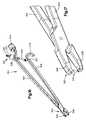
- FIG. 8is a schematic side view of an actuator for use in connecting mounting members shown in FIG. 5 to adjacent vertebrae;
- FIG. 9is a pictorial view of insertion members for use with the actuator of FIG. 8 to connect the mounting members to adjacent vertebrae of the spinal column;
- FIG. 10is a pictorial view of one of the insertion members of FIG. 9 ;
- FIG. 11is a schematic side view of the insertion member of FIG. 10 ;
- FIG. 12is a schematic top view of the insertion member of FIG. 10 ;
- FIG. 13is a sectional view of a portion of the insertion member taken along the line 13 — 13 in FIG. 12 ;
- FIG. 14is a pictorial view of a slider connectable to one of the insertion members of FIG. 9 ;
- FIG. 15is a pictorial view of a spring member for connecting the mounting member to one of the insertion members of FIG. 9 ;
- FIG. 16is a pictorial view of a surgical tool for use in inserting the artificial disc of FIG. 2 between the adjacent vertebrae;
- FIG. 17is an enlarged view of a portion of the surgical tool of FIG. 16 .
- FIGS. 1–7illustrate an apparatus or prosthesis 10 to replace a damaged or degenerated spinal disc in a spinal column.
- the apparatus 10( FIG. 6 ) is used to replace a damaged spinal disc between adjacent upper and lower vertebrae 12 and 14 of a human spinal column 16 .
- the apparatus 10( FIGS. 1–7 ) includes an artificial disc 18 and mounting members 100 that help connect the disc 18 to the adjacent vertebrae 12 and 14 .
- the mounting members 100also help position the disc 18 relative to the vertebrae 12 and 14 .
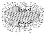
- the apparatus 10( FIG. 1 ) includes an upper or first retaining device 20 , a lower or second retaining device 60 and a resilient core 90 interposed between and adhered to the retaining devices.
- the upper and lower retaining devices 20 and 60are identical to each other and include mounting members 100 .
- the apparatus 10is symmetrical about a horizontally extending plane A ( FIG. 3 ).
- the terms “upper” and “lower”are used herein with reference to the orientation of the apparatus 10 when in the human body, as illustrated in FIG. 6 , to distinguish the two identical retaining devices for reference purposes.
- the upper retaining device 20includes an upper or first retaining ring or member 21 and a mounting member 100 .
- the artificial disc 18includes the upper retaining member 21 .
- the upper retaining member 21is rigid and made of a biocompatible material such as a biocompatible metal or polymer. It is contemplated that the upper retaining member 21 could be made of a titanium alloy.
- the upper retaining member 21has an outer surface 22 engageable with the vertebra 12 .
- An inner concave surface 24 of the upper retaining member 21is affixed or bonded to the resilient core 90 . It is contemplated that the inner surface 24 may have beads (not shown) sintered on the inner surface or a texture (not shown) etched onto the inner surface to help connect the upper retaining member 21 to the core 90 .
- a plurality of guides or ribs 26( FIGS. 3–4 ) and a central rib 28 extend from the outer surface 22 .
- the upper retaining member 21is shown as having four ribs 26 , it is contemplated that the upper retaining member may have any number of ribs 26 .
- the ribs 26engage the vertebra 12 , as shown in FIGS. 6–7 , to retain the apparatus 10 in position between the vertebrae 12 and 14 .
- the outer surface 22may also have beads (not shown) sintered on the outer surface or a texture (not shown) etched onto the outer surface to further retain the apparatus 10 between the vertebrae 12 and 14 .
- the ribs 26extend generally parallel to each other from a proximal side 30 of the disc 18 to an anterior side 32 of the disc.
- the central rib 28extends from the anterior side 32 of the disc 18 to an axially extending circular opening 36 in the upper retaining member 21 . It is contemplated that the ribs 26 and 28 may extend in any desired direction. The direction in which the ribs 26 and 28 extend is determined by the direction of insertion of the disc 18 .
- the axially extending opening 36extends through the outer surface 22 and the inner surface 24 of the upper retaining member 21 .
- the upper retaining member 21has a frustoconical surface 37 at least partially defining the opening 36 .
- An upper portion of the opening 36has a first diameter and a lower portion of the opening has a second diameter smaller than the first diameter.
- the opening 36is centrally located between two of the ribs 26 . Accordingly, there is no rib extending from the proximal side 30 of the disc 18 to the opening 36 .
- the opening 36is shown as being circular, it is contemplated that the opening may have any desired shape.
- a flange portion 38extends from the upper retaining member 21 on the anterior side 32 of the disc 18 .
- the flange portion 38has a recess 40 adjacent the central rib 28 .
- the recess 40is defined by a bottom surface 42 and side surfaces 44 and 46 extending upwardly from the bottom surface 42 .
- An oval shaped slot 48extends through the bottom surface 42 of the flange portion 38 .
- the slot 48extends in a direction transverse to the direction in which the rib 28 extends.
- the inner concave surface 24 ( FIG. 2 ) of the upper retaining member 21is affixed or bonded to the resilient core 90 .
- the upper retaining member 21includes a peripheral flange portion 50 extending toward the lower retaining device 60 .
- the flange 50encircles the core 90 .
- the flange 50has a radially inner surface 52 facing the core 90 .
- the surface 52extends radially outwardly from the concave surface 24 and toward the lower retaining device 60 .
- the surface 52 on the flange 50is spaced from the core 90 , as shown in FIG. 6 , until a predetermined load is applied to the apparatus 10 .
- the core 90deflects toward the surface 52 on the flange 90 when a load is applied to the apparatus 10 to move the upper and lower retaining devices 20 and 60 relative to each other.
- the core 90deflects into engagement with the surface 52 on the flange 50 .
- the corestiffens since further deflection of the core is restricted by the flange 50 .
- the surface 52 of the flange 50may have any desired configuration.
- the surface 52may have a first portion that extends closer to the core 90 than a second portion so that the core engages the first portion of the surface 52 prior to engaging the second portion of the surface 52 .
- the core 90may engage different portions of the surface 52 as different loads are applied to the apparatus 10 to vary the stiffness of the core at the different loads.
- the retaining member 21may have an inner surface (not shown) extending from the concave inner surface 24 to the opening 36 and spaced from the core 90 until a predetermined load is applied to the apparatus 10 .
- the core 90deflects into engagement with the inner surface (not shown) extending from the concave surface 24 to the opening 36 .
- the core 90engages the inner surface extending from the concave surface 24 to the opening 36 , the core stiffens since further deflection of the core is restricted by the retaining member 21 .
- the lower retaining device 60( FIGS. 1–2 ) is identical in configuration to the upper retaining device 20 .
- the lower retaining device 60includes a lower or second retaining member or ring 61 and a mounting member 100 .
- the disc 18includes the lower retaining member 61 .
- the lower retaining member 61is identical to the upper retaining member 21 . Accordingly, the lower retaining member 61 will not be described in detail.
- the lower retaining member 61is rigid and made from the same material as the upper retaining member 21 , such as a titanium alloy.
- the lower retaining member 61has an outer surface 62 engageable with the vertebra 14 .
- An inner concave surface 64 of the lower retaining member 61is affixed or bonded to the resilient core 90 . It is contemplated that the inner surface 64 may have beads (not shown) sintered on the inner surface or a texture (not shown) etched onto the inner surface to help connect the lower retaining member 61 to the core 90 .
- a plurality of guides or ribs 66( FIGS. 2 and 3 ) and a central rib 68 extend from the outer surface 62 .
- the lower retaining member 61may have any number of ribs 66 .
- the ribs 66engage the vertebra 14 , as shown in FIGS. 6 and 7 , to retain the apparatus 10 in position between the vertebrae 12 and 14 .
- the outer surface 62may also have beads (not shown) sintered on the outer surface or a texture (not shown) etched onto the outer surface to further retain the apparatus 10 between the vertebrae 12 and 14 .
- the ribs 66extend generally parallel to each other from the proximal side 30 of the disc 18 to the anterior side 32 .
- the central rib 68( FIG. 2 ) extends from the anterior side 32 to an axially extending circular opening 70 in the lower retaining member 61 . It is contemplated that the ribs 66 and 68 may extend in any desired direction. The direction in which the ribs 66 and 68 extend is determined by the direction of insertion of the disc 18 .
- the axially extending opening 70extends through the outer surface 62 and the inner surface 64 of the upper retaining member 61 .
- the lower retaining member 61has a frustoconical surface 71 at least partially defining the opening 70 .
- a lower portion of the opening 70has a first diameter and an upper portion of the opening has a second diameter smaller than the first diameter.
- the opening 70is centrally located between two of the ribs 66 . Accordingly, there is no rib extending from the proximal side 30 of the disc 18 to the opening 70 .
- the opening 70is described as being circular, it is contemplated that the opening may have any desired shape.
- a flange portion 72extends from the lower retaining member 61 on the anterior side 32 of the disc 18 .
- the flange portion 72has a recess 74 adjacent the central rib 68 .
- the recess 74is defined by an upper surface 76 and side surfaces 78 and 80 extending downwardly from the upper surface 76 .
- An oval shaped slot 82extends through the upper surface 76 of the flange portion 72 .
- the slot 82extends in a direction transverse to the direction in which the central rib 68 extends.
- the inner concave surface 64 ( FIG. 2 ) of the lower retaining member 61is affixed or bonded to the resilient core 90 .
- the lower retaining member 61includes a peripheral flange portion 84 extending toward the upper retaining device 20 .
- the flange 84encircles the core 90 .
- the flange 84has a radially inner surface 86 facing the core 90 .
- the surface 86extends radially outwardly from the concave surface 64 and toward the upper retaining device 20 .
- the surface 86 on the flange 84is spaced from the core 90 , as shown in FIG. 6 , until a predetermined load is applied to the apparatus 10 .
- the core 90deflects toward the surface 86 on the flange 84 when a load is applied to the apparatus 10 to move the upper and lower retaining devices 20 and 60 relative to each other.
- a predetermined loadis applied to the apparatus 10 , as shown in FIG. 7 , the core 90 deflects into engagement with the surface 86 on the flange 84 .
- the core 90 engages the flange 84the core stiffens since further deflection of the core is restricted by the flange 84 .
- the surface 86 of the flange 84may have any desired configuration.
- the surface 86may have a first portion that extends closer to the core 90 than a second portion so that the core engages the first portion of the surface 86 prior to engaging the second portion of the surface 86 .
- the core 90may engage different portions of the surface 86 as different loads are applied to the apparatus 10 to vary the stiffness of the core at different loads.
- the flange 84 on the lower retaining member 61may engage the flange 50 on the upper retaining member 21 when a predetermined load is applied to the apparatus 10 .
- the retaining member 61may have an inner surface (not shown) extending from the concave inner surface 64 to the opening 70 and spaced from the core 90 until a predetermined load is applied to the apparatus 10 .
- the core 90deflects into engagement with the inner surface (not shown) extending from the concave surface 64 to the opening 70 .
- the core 90engages the inner surface extending from the concave surface 64 to the opening 70 , the core stiffens since further deflection of the core is restricted by the retaining member 61 .
- the resilient core 90is one-piece and may be made of a urethane silicone blend manufactured by the Polymer Technology Group located in Berkley, Calif.
- the resilient core 90may be adhered or bonded to the upper and lower retaining members 21 and 61 in any manner known in the art. It is contemplated that the resilient core 90 could be insert molded, transfer molded or injection molded between the upper and lower retaining members 21 and 61 .
- the core 90may be molded between the upper and lower retaining members 21 and 61 by injecting the material for the core through one of the openings 36 or 70 in the upper and lower retaining members.
- the resilient core 90may be made of a polymer that is a silicone-polycarbonate-urethane copolymer by the name of CarboSilTM manufactured by the Polymer Technology Group located in Berkley, Calif.
- the resilient core 90is prepared through a multi-step bulk synthesis during which polydimethylsiloxane is incorporated into the polymer soft segment with aliphatic, hydroxyl-terminated polycarbonate oligomers.
- the hard segmentconsists of an aromatic diisocyanate with a low molecular weight glycol chain extender. The copolymer chains are terminated with silicone.
- the material of the resilient core 90combines the biocompatibility and biostability of silicone elastomers with the processibility and toughness of thermoplastic urethane elastomers.
- the material of the resilient core 90has a relatively high hard segment content that softens significantly upon reaching equilibrium with the body of a patient. The relevant equilibrium involves thermal equilibrium with the body at approximately 37° C. and equilibrium water and solute uptake by the polymer after being implanted in the body.
- the material of the resilient core 90has a decreased modulus at 37° C. compared to that at room temperature. Accordingly, the higher durometer polymer can be used for its biostability, since conditions in the human body lower the modulus of the polymer to the desired range of compressive stiffness.
- the resilient core 90is wedge shaped.
- the upper retaining member 21is spaced from the lower retaining member 61 a first distance adjacent the proximal side 30 of the disc 18 .
- the upper retaining member 21is spaced from the lower retaining member 61 a second distance greater than the first distance adjacent the anterior side 32 of the disc 18 . It is contemplated that the upper retaining member 21 may be spaced from the lower retaining member 61 by any desired distances.
- the core 90has an upper or first convex surface 92 .
- the upper convex surface 92is affixed to the concave inner surface 24 of the upper retaining member 21 .
- a lower or second convex surface 94is affixed to the concave inner surface 64 of the lower retaining member 61 .
- the core 90includes a radially outer surface 96 .
- Arcuate transition surfaces 98extend between the radially outer surface 96 and the upper and lower surfaces 92 and 94 .
- the radially outer surface 96is spaced from the flanges 50 and 84 on the upper and lower retaining members 21 and 61 until the predetermined load is applied to the apparatus 10 .
- the peripheral surface 96 and the transition surfaces 98may have any desired configuration.
- the surfaces 96 and 98may have first portions that extend closer to the flanges 50 and 84 than second portions so that the first portions engage the flanges 50 and 84 prior to the second portions. Accordingly, the different portions of the surfaces 96 and 98 may engage the flanges 50 and 84 as different loads are applied to the apparatus 10 to vary the stiffness of the core 90 at different loads.
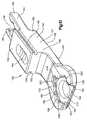
- Each of the retaining devices 20 and 60includes a mounting member 100 to help connect the disc 18 to the vertebrae 12 and 14 .
- the mounting members 100also help position the disc 18 between the vertebrae 12 and 14 .
- the mounting members 100( FIG. 6 ) extend into the openings 36 and 70 in the retaining members 21 and 61 when the apparatus 10 is connected to the vertebrae 12 and 14 .
- the disc 18is inserted between the vertebrae 12 and 14 after the mounting members 100 are connected to the vertebrae.
- the ribs or guides 26 and 66 on opposite sides of the openings 36 and 70 of the disc 18engage the mounting members 100 to guide the disc into a desired position between the vertebrae 12 and 14 .
- the mounting members 100are identical to each other. Accordingly, only one mounting member 100 will be described in detail.
- the mounting member 100( FIG. 5 ) is rigid and made of a biocompatible material such as a biocompatible metal or polymer. It is contemplated that the mounting member 100 could be made of a titanium alloy.
- the mounting member 100has an outer surface 102 that faces the vertebra.
- An inner concave surface 104 of the mounting member 100faces the resilient core 90 .
- the inner concave surface 104 of the mounting member 100 of the upper retaining device 20faces the upper surface 92 of the core 90 .
- the inner concave surface 104 of the mounting member 100 of the lower retaining device 60faces the lower surface 94 of the core 90 .
- the resilient core 90deflects toward the concave surfaces 104 when a load is applied to the apparatus 10 to move the upper and lower retaining devices 20 and 60 relative to each other.
- the core 90deflects into the openings 36 and 70 in the upper and lower retaining members 21 and 61 and into engagement with the concave surfaces 104 when the spine 16 is subject to a predetermined load, as shown in FIG. 7 .
- the resilient corestiffens since further deflection of the core toward the retaining devices 20 and 60 is restricted.
- the retaining member 100may have an axially extending opening to permit the escape of gas from between the core 90 and the mounting member.
- the surfaces 104 of the mounting member 100may have any desired configuration.
- the core 90may engage different portions of the surfaces 104 as different loads are applied to the apparatus 10 to vary the stiffness of the core 90 at different loads. It is also contemplated that the surface 104 of the mounting member 100 of the retaining device 20 may have a different configuration than the surface 104 of the mounting member 100 of the retaining device 61 .
- Projections 106extend from the outer surface 102 of the mounting member 100 .
- the projections 106engage the vertebrae 12 and 14 to help retain the apparatus 10 in position between the vertebra 12 and 14 .
- the mounting member 100is shown having four projections 106 , it is contemplated that the mounting member may have any number of projections. It is contemplated that the projections 106 may have any desired shapes, sizes, and/or tip configurations.
- the projections 106may include passages for bone ingrowth, have barbs, and/or have hooks.
- the mounting member 100includes a circular body 110 from which the projections 106 extend. Although the body 110 of the mounting member 100 is shown as being circular, it is contemplated that the body 110 may have any desired configuration that permits the mounting member 100 to slide into the openings 36 and 70 in the disc 18 .
- the body 110 of the mounting member 100has a radially outer frustoconical surface 112 .
- a rounded transition surface 113extends from the radially outer surface 112 to the concave surface 104 .
- the body 110has a first diameter adjacent the outer surface 102 and a second diameter adjacent the transition surface 113 that is smaller than the first diameter.
- the radially outer surfaces 112 and/or the transition surfaces 113 of the mounting members 100engage the ribs or guides 26 and 66 on the retaining members 21 and 61 to guide movement of the disc 18 in a first posterior direction relative to the mounting members and the vertebrae 12 and 14 .
- the central ribs 28 and 68 on the upper and lower retaining members 21 and 61act as stops to prevent movement of the disc 18 in the first direction after the disc has been inserted to a desired depth.
- the central ribs 28 and 68engage the radially outer surfaces 112 and/or the transition surfaces 113 on the mounting member 100 .
- the radially outer surfaces 112 and/or the transition surfaces 113guide relative movement between the mounting members and the retaining members 21 and 61 in second directions extending transverse to the first directions so that the mounting members move into the openings 36 and 70 in the disc 18 .
- the engagement of the surfaces 112 with the surfaces 37 and 71creates interference fits between the mounting members 100 and the disc 18 . Accordingly, the disc 18 is prevented from moving relative to the mounting members 100 .
- the radially outer surface 112has four recesses 114 , two of which are shown in FIG. 5 .
- the recesses 114are located at 90° relative to each other.
- the mounting member 100is described as having four recesses 114 , it is contemplated that the mounting member 100 may have any number of recesses.
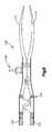
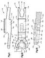
- the mounting members 100may be connected to the vertebrae 12 and 14 using a surgical tool that includes an actuator 120 and a pair of insertion members 140 ( FIGS. 8 and 9 ).
- the mounting members 100are connected to the members 140 and the actuator 120 moves the members away from each other to connect the mounting members to the vertebrae.
- the actuator 120( FIG. 8 ) may be a modular spine distractor manufactured by Friedrich GmbH of Solingen, Germany to which the members 140 are connected.
- the actuator 120is known in the art and will not be described in detail.
- the actuator 120includes a pair of actuation handles 122 and a pair of separators 124 that are connectable to the members 140 .
- the handles 122are connected to the separators 124 by a linkage system 126 .
- the linkage system 126causes the separators 124 to move away from each other.
- the actuator 120also includes a locking mechanism 128 for locking the separators 124 at a desired distance from each other.
- the insertion members 140( FIGS. 9–13 ) are connectable to the separators 124 .
- the members 140are identical to each other. Accordingly, only one member 140 will be described in detail.
- the member 140includes a connecting end 144 that is insertable into an opening (not shown) in one of the separators 124 of the actuator 120 .
- the end 144includes a pair of projections 146 .
- the projections 146extend generally parallel to each other and define a channel 148 between them.
- the end 144is inserted into the opening (not shown) in the separator 124 of the actuator 120 to connect the member 140 to the actuator in a known manner.
- the member 140may be removed from the separator 124 in a known manner. It is contemplated that the end 144 of the member 140 hay have any desired configuration to connect the member to a desired actuator.
- the projections 146extend from a first end 150 of a central body 152 of the member 140 .
- the central body 152has an upper surface 154 and a parallel lower surface 156 extending from the first end 150 to a second end 158 of the central body.
- the projections 146extend at an angle to the surfaces 154 and 156 . It is contemplated that the projections 146 may extend at any desired angle to the surfaces 154 and 156 .
- the upper surface 154has a scalloped recess 164 .
- Side surfaces 160 and 162extend from the upper surface 154 to the lower surface 156 .
- a pair of longitudinally extending grooves 166located in the side surfaces 160 and 162 extend along the body 152 .
- the grooves 166extend from the first end 150 to the second end 158 .
- a slider 168may be connected to the body 152 of the member 140 .
- the slider 168engages one of the vertebrae 12 and 14 to prevent further insertion of the mounting members 100 in the proximal direction between the vertebrae.
- the slider 168includes a main body portion 170 with a threaded opening 172 .
- a pair of flanges 174extend downwardly from the body portion 170 .
- the flanges 174( FIG. 14 ) extend generally parallel to each other and include portions 176 extending toward each other. The portions 176 are received in the grooves 166 in the body 152 of the member 140 .
- the slider 168includes a vertically extending groove 178 in a surface 179 that faces away from the connecting end 144 of the member 140 .
- the slider 168may be moved relative the body 152 toward and away from the end 144 of the member 140 .
- a set screw(not shown) is threaded into the opening 172 and extends into the scalloped recess 164 to prevent movement of the slider 168 relative to the body 152 .
- the scalloped recess 164defines a plurality of positions for the slider 168 relative to the member 140 .
- An insertion end 180 ( FIGS. 9–13 ) of the member 140extends from the second end 158 of the body 152 .
- the insertion end 180extends at an angle to the upper and lower surfaces 154 and 156 of the body 152 and generally parallel to the projections 146 . It is contemplated that the insertion end 180 may extend at any desired angle relative to the surfaces 154 and 156 .
- the insertion end 180( FIG. 11 ) has a lower surface 182 that extends at an angle to the lower surface 156 of the body 152 .
- the insertion end 180( FIG. 12 ) includes a recess 184 for receiving the mounting member 100 .
- the recess 184is generally U-shaped with an open end 186 through which the mounting member 100 may be inserted into the recess and removed from the recess.
- the recess 184is defined by sidewalls 188 and 190 interconnected by a back wall 192 .
- a bottom wall 194extends generally perpendicular to the sidewalls 188 and 190 and the back wall 192 .
- the sidewall 188has a notch 198 extending radially outwardly.
- the sidewall 190includes a notch 200 extending radially outwardly.
- the back wall 192has a notch 202 extending toward the body 152 .
- a groove 206( FIGS. 10 and 13 ) is formed in the sidewall 188 extending from adjacent the open end 186 to the notch 198 .
- a groove 208extends from the notch 198 to the notch 202 .
- a groove (not shown) similar to the groove 208 extending between the notch 202 and the notch 200is formed in the sidewall 190 .
- Another groove (not shown) similar to the groove 206 extending from the notch 200 to adjacent the open end 186is formed in the sidewall 190 .
- a first circular opening 216extends through the bottom wall 194 and is centrally located in the recess 184 .
- the opening 216permits removal of the mounting member 100 from the recess 184 if needed.
- a second smaller circular opening 218extends through the bottom wall 194 and is located in the notch 202 .
- a spring member 230( FIGS. 9 and 15 ) is received in the recess 184 to hold the mounting member 100 in the recess.
- the spring member 230is generally U-shaped and includes a pair of arms 232 and 234 extending from a base 236 .
- a projection 238extends from the base 236 in a direction opposite from the arms 232 and 234 .
- the projection 238has a circular opening 240 for receiving a pin (not shown) to connect the spring member 230 to the member 140 .
- the pin(not shown) extends through the opening 240 in the spring member 230 and into the opening 218 in the member 140 to connect the spring member to the member 140 .
- the arm 232includes an upwardly extending end 246 that engages the mounting member 100 to retain the mounting member in the member 140 .
- the end 246has a radially inwardly extending projection 248 .
- the projection 248extends into one of the recesses 114 in the mounting member 100 to retain the mounting member in the member 140 .
- the arm 234has an upwardly extending end 252 .
- the end 252has a radially inwardly extending projection 254 .
- the projection 254extends into one of the recesses 114 in the mounting member 100 to retain the mounting member in the member 140 .
- the spring member 230is inserted into the recess 184 through the open end 186 .
- the arms 232 and 234extend into the groove 206 in the sidewall 188 and the groove (not shown) in the sidewall 190 extending from the notch 200 to adjacent the open end 186 , as the spring 230 is being inserted into the recess 184 .
- the ends 246 and 252 of the arms 232 and 234move toward each other. When the ends 246 and 252 are adjacent the notches 198 and 200 , the ends 246 and 252 move away from each other.
- the arm 232When the spring 230 ( FIG. 9 ) is inserted in the recess 184 , the arm 232 extends into the groove 208 and the arm 234 extends into the groove (not shown) extending from the notch 202 to the notch 200 in the insertion end 180 of the member 140 .
- the opening 240 in the projection 238 of the spring member 230is aligned with the opening 218 in the insertion end 180 .
- a pin(not shown) extends through the opening 240 in the spring member 230 and into the opening 218 to retain the spring member in the recess 184 .
- the ends 246 and 252extend upwardly into the notches 198 and 200 in the sidewalls 188 and 190 .
- the endsUpon insertion of the mounting member 100 between the ends 246 and 252 of the spring 230 , the ends move radially outwardly away from each other into the notches 198 and 200 until the recesses 114 are aligned with the projections 248 and 254 .
- the ends 246 and 252move toward each other into the recesses to retain the mounting member 100 in the insertion end 180 .
- the mounting member 100may be removed from the recess 184 by overcoming the retaining force applied by the spring member 230 .
- FIGS. 16 and 17An insertion tool 300 for inserting the disc 18 between the vertebrae 12 and 14 after the mounting members 100 are connected to the vertebrae 12 and 14 is illustrated in FIGS. 16 and 17 .
- the tool 300( FIG. 16 ) resembles a common pair of scissors and has a pair of legs 302 and 304 pivotally connected to one another.
- the tool 300includes a grasping end 306 formed by a pair of jaws 308 on the legs 302 and 304 .
- the jaws 308( FIG. 17 ) include oval shaped projections 310 extending toward each other. The projections 310 are inserted into the openings 48 and 82 in the disc 18 to grasp the disc for insertion between the vertebrae 12 and 14 .
- the leg 302( FIG. 15 ) has an enlarged end 312 opposite the jaw 308 .
- the enlarged end 312may be struck with a mallet to drive the disc 18 between the vertebrae 12 and 14 if needed.
- the leg 304has a curved handle 314 opposite the jaw 308 .
- the handle 314is easily grasped by a surgeon for manipulating the tool 300 .
- a locking mechanism 320prevents the jaws 308 from pivoting away from each other after the projections 310 have been inserted into the openings 48 and 82 in the disc 18 .
- the locking mechanism 320includes a rod 322 pivotally connected to a mounting portion 324 extending from the leg 304 .
- the rod 322has a threaded end 326 that extends through an opening 328 in the leg 302 .
- a nut 332threadably engages the end 326 of the rod 322 and engages the leg 302 to prevent the jaws 308 from pivoting away from each other.
- an anterior space adjacent the vertebraeis exposed using a retroperitoneal or transperitoneal approach.
- a midline referenceis established.
- a midline markersuch as a K-wire, is placed to maintain a reference point to the center of one of the vertebrae 12 and 14 .
- the space between the vertebrae 12 and 14is distracted and the damaged disc between the vertebrae is excised. After the damaged disc is excised, the cartilaginous end plates are removed from the vertebrae 12 and 14 .
- the vertebrae 12 and 14are then sculpted as desired.
- the appropriate size apparatus 10is determined by using trial sizers.
- the trial sizersare similar to the disc 18 .
- the trial sizersare inserted between the vertebrae 12 and 14 to determine the desired footprint, wedge angle, and disc height needed to replace the excised disc.
- the desired footprint, wedge angle and disc heightare confirmed using fluoroscopy.
- the mounting members 100are then inserted into the vertebrae 12 and 14 .
- the appropriate members 140are selected based upon the desired wedge angle for use between the vertebrae 12 and 14 .
- the mounting members 100are inserted into the recesses 184 in the member 140 .
- the insertion ends 180 of the members 140are inserted between the vertebrae 12 and 14 until the midline marker extends into the groove 178 on the slider 168 and the slider 168 engages the anterior ridge of one of the vertebrae 12 and 14 directly under the midline marker.
- the insertion ends 180 of the members 140have been inserted into the desired depth, the insertion ends are moved away from each other by the actuator 120 to insert the projections 106 on the mounting members 100 into the vertebrae 12 and 14 .
- the members 140are removed from between the vertebrae 12 and 14 leaving the mounting members behind.
- a trial sizermay be reinserted between the vertebrae. Verification of the position of the trial sizer is achieved using fluoroscopy. If it is determined that the mounting members 100 are not in the desired positions, the mounting members can be easily removed and repositioned in the vertebrae.
- the insertion tool 300is connected with the disc 18 .
- the disc 18is then inserted between the vertebrae 12 and 14 .
- the ribs 26 and 66 on opposite sides of the openings 36 and 70engage the surfaces 112 and 113 on the mounting members 100 to guide insertion of the disc.
- the central ribs 28 and 68engage the mounting members 100 when the disc 18 has been inserted to the desired depth between the vertebrae 12 and 14 .
- the ribs 26 , 28 , 66 , and 68 on the disc 18guide insertion of the mounting members 100 into the openings 36 and 70 in the disc 18 .
- the tool 300is removed from the disc.
- the ribs 26 , 28 , 66 and 68 on the disc 18engage the vertebrae 12 and 14 when the mounting members 100 are inserted in the openings 36 and 70 in the disc 18 .
- the mounting members 100 and ribs 26 , 28 , 66 and 68retain the apparatus 10 in position between the vertebrae 12 and 14 .
- the upper retaining device 20When the apparatus 10 is in use in the spinal column 16 , the upper retaining device 20 is affixed to the vertebra 12 .
- the ribs 26 and 28 and the projections 106 on the mounting member 100resist relative movement between the upper retaining device 20 and vertebra 12 .
- the lower retaining device 60is affixed to the vertebra 14 .
- the ribs 66 and 68 and the projections 106 on the mounting member 100resist relative movement between the lower retaining device 60 and the vertebra 14 .
- the resilient core 90deflects toward the concave surfaces 104 on the mounting members 100 .
- the resilient core 90also deflects toward the surfaces 52 and 86 on the retaining members 21 and 61 when a load is applied to the apparatus. Accordingly, the core 90 expends energy to reduce stress in the core upon relative movement of the upper and lower retaining devices 20 and 60 to provide a relatively long fatigue life for the apparatus 10 .
- the resilient core 90deflects into engagement with the surfaces 104 of the mounting members 100 when a predetermined load is applied.
- the core 90also deflects into engagement with the surfaces 52 and 86 on the retaining members 21 and 61 when a predetermined load is applied. Accordingly, the core 90 stiffens when the core engages the surfaces 104 , 52 , and 86 since further deflection of the core is restricted. It is contemplated that the core 90 may engage the surfaces 104 , 52 , and 86 at different applied loads.
- the mounting members 100may have grooves that ribs on the disc 18 extend into to guide insertion of the disc. It is also contemplated that the mounting members 100 may have ribs that extend into grooves in the disc 18 to guide insertion of the disc. Furthermore, it is contemplated that the disc 18 may be inserted between the vertebrae 12 and 14 without use of the mounting members 100 . If the disc 18 is used without the mounting members 100 , it is contemplated that the retaining members 21 and 61 of the retaining devices 20 and 60 would include inner concave surfaces similar to the inner concave surfaces 104 of the mounting members. The core 90 would be spaced from the inner concave surfaces on the retaining members 21 and 61 and deflect into engagement with the inner concave surfaces when a predetermined load was applied to the apparatus 10 .
Landscapes
- Health & Medical Sciences (AREA)
- Engineering & Computer Science (AREA)
- Biomedical Technology (AREA)
- Orthopedic Medicine & Surgery (AREA)
- Transplantation (AREA)
- Neurology (AREA)
- Heart & Thoracic Surgery (AREA)
- Oral & Maxillofacial Surgery (AREA)
- Cardiology (AREA)
- Vascular Medicine (AREA)
- Life Sciences & Earth Sciences (AREA)
- Animal Behavior & Ethology (AREA)
- General Health & Medical Sciences (AREA)
- Public Health (AREA)
- Veterinary Medicine (AREA)
- Physical Education & Sports Medicine (AREA)
- Prostheses (AREA)
- Surgical Instruments (AREA)
Abstract
Description
Claims (28)
Priority Applications (14)
| Application Number | Priority Date | Filing Date | Title |
|---|---|---|---|
| US10/731,964US7695517B2 (en) | 2003-12-10 | 2003-12-10 | Apparatus for replacing a damaged spinal disc |
| US10/732,660US7128761B2 (en) | 2003-12-10 | 2003-12-10 | Method and apparatus for replacing a damaged spinal disc |
| US10/731,942US7588600B2 (en) | 2003-12-10 | 2003-12-10 | Method for replacing a damaged spinal disc |
| PCT/US2004/041402WO2005058194A2 (en) | 2003-12-10 | 2004-12-08 | Method and apparatus for replacing a damaged spinal disc |
| AU2004299008AAU2004299008B2 (en) | 2003-12-10 | 2004-12-08 | Method and apparatus for replacing a damaged spinal disc |
| EP11006513AEP2387976A1 (en) | 2003-12-10 | 2004-12-08 | Method and apparatus for replacing a damaged spinal disc |
| CN2004800396056ACN1901854B (en) | 2003-12-10 | 2004-12-08 | Method and apparatus for replacing a damaged intervertebral disc |
| CA002549101ACA2549101C (en) | 2003-12-10 | 2004-12-08 | Method and apparatus for replacing a damaged spinal disc |
| AT04813690TATE534350T1 (en) | 2003-12-10 | 2004-12-08 | DEVICE FOR REPLACING A DAMAGED DISC |
| EP04813690AEP1703869B1 (en) | 2003-12-10 | 2004-12-08 | Apparatus for replacing a damaged spinal disc |
| CN2010101281076ACN101816596B (en) | 2003-12-10 | 2004-12-08 | Apparatus for replacing a damaged spinal disc |
| JP2006544018AJP4750042B2 (en) | 2003-12-10 | 2004-12-08 | Equipment replaced with a damaged spinal disc |
| CA2650756ACA2650756C (en) | 2003-12-10 | 2004-12-08 | Method and apparatus for replacing a damaged spinal disc |
| KR1020067013881AKR100753465B1 (en) | 2003-12-10 | 2004-12-08 | Method and apparatus for replacing damaged spinal disc |
Applications Claiming Priority (1)
| Application Number | Priority Date | Filing Date | Title |
|---|---|---|---|
| US10/732,660US7128761B2 (en) | 2003-12-10 | 2003-12-10 | Method and apparatus for replacing a damaged spinal disc |
Publications (2)
| Publication Number | Publication Date |
|---|---|
| US20050131544A1 US20050131544A1 (en) | 2005-06-16 |
| US7128761B2true US7128761B2 (en) | 2006-10-31 |
Family
ID=34652918
Family Applications (3)
| Application Number | Title | Priority Date | Filing Date |
|---|---|---|---|
| US10/731,942Active2028-03-31US7588600B2 (en) | 2003-12-10 | 2003-12-10 | Method for replacing a damaged spinal disc |
| US10/732,660Expired - LifetimeUS7128761B2 (en) | 2003-12-10 | 2003-12-10 | Method and apparatus for replacing a damaged spinal disc |
| US10/731,964Active - Reinstated2028-12-04US7695517B2 (en) | 2003-12-10 | 2003-12-10 | Apparatus for replacing a damaged spinal disc |
Family Applications Before (1)
| Application Number | Title | Priority Date | Filing Date |
|---|---|---|---|
| US10/731,942Active2028-03-31US7588600B2 (en) | 2003-12-10 | 2003-12-10 | Method for replacing a damaged spinal disc |
Family Applications After (1)
| Application Number | Title | Priority Date | Filing Date |
|---|---|---|---|
| US10/731,964Active - Reinstated2028-12-04US7695517B2 (en) | 2003-12-10 | 2003-12-10 | Apparatus for replacing a damaged spinal disc |
Country Status (9)
| Country | Link |
|---|---|
| US (3) | US7588600B2 (en) |
| EP (2) | EP2387976A1 (en) |
| JP (1) | JP4750042B2 (en) |
| KR (1) | KR100753465B1 (en) |
| CN (2) | CN1901854B (en) |
| AT (1) | ATE534350T1 (en) |
| AU (1) | AU2004299008B2 (en) |
| CA (2) | CA2549101C (en) |
| WO (1) | WO2005058194A2 (en) |
Cited By (76)
| Publication number | Priority date | Publication date | Assignee | Title |
|---|---|---|---|---|
| US20050043804A1 (en)* | 1999-05-17 | 2005-02-24 | Vanderbilt University | Intervertebral disc replacement prosthesis |
| US20050131543A1 (en)* | 2003-12-10 | 2005-06-16 | Axiomed Spine Corporation | Method and apparatus for replacing a damaged spinal disc |
| US20060058808A1 (en)* | 2004-09-08 | 2006-03-16 | Susanne Schneid | Surgical instrument |
| US20060149273A1 (en)* | 2004-12-06 | 2006-07-06 | Axiomed Spine Corporation | Method and apparatus for replacing a spinal disc |
| US20070191958A1 (en)* | 2006-02-15 | 2007-08-16 | Abdou M S | Devices and Methods for Inter-Vertebral Orthopedic Device Placement |
| US20070282448A1 (en)* | 2006-05-26 | 2007-12-06 | Abdou M S | Inter-Vertebral Disc Motion Devices and Methods of Use |
| US20080319548A1 (en)* | 2007-06-22 | 2008-12-25 | Axiomed Spine Corporation | Artificial disc |
| WO2008134703A3 (en)* | 2007-04-30 | 2009-01-08 | Globus Medical Inc | Flexible spine stabilization system |
| US20090182429A1 (en)* | 2008-01-16 | 2009-07-16 | Warsaw Orthopedic, Inc. | Total joint Replacement |
| US20090248161A1 (en)* | 2008-03-20 | 2009-10-01 | K2M, Inc. | Artificial disc replacement device |
| US7771478B2 (en) | 2003-04-04 | 2010-08-10 | Theken Spine, Llc | Artificial disc prosthesis |
| US20100204796A1 (en)* | 2009-02-11 | 2010-08-12 | IMDS, Inc. | Intervertebral implant with integrated fixation |
| US20110035006A1 (en)* | 2009-08-07 | 2011-02-10 | Ebi, Llc | Toroid-Shaped Spinal Disc |
| US20110035010A1 (en)* | 2009-08-07 | 2011-02-10 | Ebi, Llc | Toroid-shaped spinal disc |
| WO2011106668A3 (en)* | 2010-02-26 | 2012-01-26 | Biomedflex Llc | Prosthetic joint |
| US8257439B2 (en) | 2004-12-22 | 2012-09-04 | Ldr Medical | Intervertebral disc prosthesis |
| US8267999B2 (en) | 2002-11-05 | 2012-09-18 | Ldr Medical | Intervertebral disc prosthesis |
| US8303660B1 (en) | 2006-04-22 | 2012-11-06 | Samy Abdou | Inter-vertebral disc prosthesis with variable rotational stop and methods of use |
| US8308812B2 (en) | 2006-11-07 | 2012-11-13 | Biomedflex, Llc | Prosthetic joint assembly and joint member therefor |
| US8343219B2 (en) | 2007-06-08 | 2013-01-01 | Ldr Medical | Intersomatic cage, intervertebral prosthesis, anchoring device and implantation instruments |
| US8449616B2 (en) | 2011-03-15 | 2013-05-28 | Axiomed Spine Corporation | Apparatus for replacing a damaged spinal disc |
| US8465546B2 (en) | 2007-02-16 | 2013-06-18 | Ldr Medical | Intervertebral disc prosthesis insertion assemblies |
| US8512413B2 (en) | 2006-11-07 | 2013-08-20 | Biomedflex, Llc | Prosthetic knee joint |
| US8771284B2 (en) | 2005-11-30 | 2014-07-08 | Ldr Medical | Intervertebral disc prosthesis and instrumentation for insertion of the prosthesis between the vertebrae |
| US8858635B2 (en) | 2004-02-04 | 2014-10-14 | Ldr Medical | Intervertebral disc prosthesis |
| US8974532B2 (en) | 2004-04-28 | 2015-03-10 | Ldr Medical | Intervertebral disc prosthesis |
| US8979932B2 (en) | 2005-09-23 | 2015-03-17 | Ldr Medical | Intervertebral disc prosthesis |
| US9005307B2 (en) | 2006-11-07 | 2015-04-14 | Biomedflex, Llc | Prosthetic ball-and-socket joint |
| US9033993B2 (en) | 2009-11-03 | 2015-05-19 | Howmedica Osteonics Corp. | Intervertebral implant with integrated fixation |
| US9039774B2 (en) | 2012-02-24 | 2015-05-26 | Ldr Medical | Anchoring device and system for an intervertebral implant, intervertebral implant and implantation instrument |
| US9044337B2 (en) | 2009-12-31 | 2015-06-02 | Ldr Medical | Anchoring device and system for an intervertebral implant, intervertebral implant and implantation instrument |
| US9078765B2 (en) | 2001-07-13 | 2015-07-14 | Ldr Medical | Vertebral cage device with modular fixation |
| US9179940B2 (en) | 2005-12-06 | 2015-11-10 | Globus Medical, Inc. | System and method for replacement of spinal motion segment |
| US9254130B2 (en) | 2011-11-01 | 2016-02-09 | Hyun Bae | Blade anchor systems for bone fusion |
| US9333095B2 (en) | 2001-05-04 | 2016-05-10 | Ldr Medical | Intervertebral disc prosthesis, surgical methods, and fitting tools |
| US9463091B2 (en) | 2009-09-17 | 2016-10-11 | Ldr Medical | Intervertebral implant having extendable bone fixation members |
| US9480511B2 (en) | 2009-12-17 | 2016-11-01 | Engage Medical Holdings, Llc | Blade fixation for ankle fusion and arthroplasty |
| US9566157B2 (en) | 2006-11-07 | 2017-02-14 | Biomedflex, Llc | Three-member prosthetic joint |
| US9615856B2 (en) | 2011-11-01 | 2017-04-11 | Imds Llc | Sacroiliac fusion cage |
| US9675389B2 (en) | 2009-12-07 | 2017-06-13 | Samy Abdou | Devices and methods for minimally invasive spinal stabilization and instrumentation |
| US9700434B2 (en) | 2009-08-10 | 2017-07-11 | Howmedica Osteonics Corp. | Intervertebral implant with integrated fixation |
| US9713535B2 (en) | 2006-02-15 | 2017-07-25 | Ldr Medical | Transforaminal intersomatic cage for an intervertebral fusion graft and an instrument for implanting the cage |
| US9877842B2 (en) | 2014-01-30 | 2018-01-30 | Ldr Medical | Anchoring device for a spinal implant, spinal implant and implantation instrumentation |
| US9925051B2 (en) | 2010-12-16 | 2018-03-27 | Engage Medical Holdings, Llc | Arthroplasty systems and methods |
| US9937050B2 (en) | 2013-05-16 | 2018-04-10 | Ldr Medical | Vertebral implant, vertebral fastening device of the implant and implant instrumentation |
| US10182923B2 (en) | 2015-01-14 | 2019-01-22 | Stryker European Holdings I, Llc | Spinal implant with porous and solid surfaces |
| US10238382B2 (en) | 2012-03-26 | 2019-03-26 | Engage Medical Holdings, Llc | Blade anchor for foot and ankle |
| US10390955B2 (en) | 2016-09-22 | 2019-08-27 | Engage Medical Holdings, Llc | Bone implants |
| US10456272B2 (en) | 2017-03-03 | 2019-10-29 | Engage Uni Llc | Unicompartmental knee arthroplasty |
| US10478310B2 (en) | 2014-05-06 | 2019-11-19 | Ldr Medical, S.A.S. | Vertebral implant, device for vertebral attachment of the implant and instrumentation for implantation thereof |
| US10537666B2 (en) | 2015-05-18 | 2020-01-21 | Stryker European Holdings I, Llc | Partially resorbable implants and methods |
| US10548740B1 (en) | 2016-10-25 | 2020-02-04 | Samy Abdou | Devices and methods for vertebral bone realignment |
| US10575961B1 (en) | 2011-09-23 | 2020-03-03 | Samy Abdou | Spinal fixation devices and methods of use |
| US10603185B2 (en) | 2004-02-04 | 2020-03-31 | Ldr Medical | Intervertebral disc prosthesis |
| US10617531B2 (en) | 2015-10-26 | 2020-04-14 | K2M, Inc. | Cervical disc and instrumentation |
| US10695105B2 (en) | 2012-08-28 | 2020-06-30 | Samy Abdou | Spinal fixation devices and methods of use |
| US10765527B2 (en) | 2017-09-29 | 2020-09-08 | Axiomed, LLC | Artificial disk with sensors |
| US10835388B2 (en) | 2017-09-20 | 2020-11-17 | Stryker European Operations Holdings Llc | Spinal implants |
| US10857003B1 (en) | 2015-10-14 | 2020-12-08 | Samy Abdou | Devices and methods for vertebral stabilization |
| US10918498B2 (en) | 2004-11-24 | 2021-02-16 | Samy Abdou | Devices and methods for inter-vertebral orthopedic device placement |
| US10918494B2 (en) | 2016-04-26 | 2021-02-16 | K2M, Inc. | Orthopedic implant with integrated core |
| US10973648B1 (en) | 2016-10-25 | 2021-04-13 | Samy Abdou | Devices and methods for vertebral bone realignment |
| US11006982B2 (en) | 2012-02-22 | 2021-05-18 | Samy Abdou | Spinous process fixation devices and methods of use |
| US11129645B2 (en) | 2006-02-07 | 2021-09-28 | P Tech, Llc | Methods of securing a fastener |
| US11134995B2 (en) | 2006-02-07 | 2021-10-05 | P Tech, Llc | Method and devices for intracorporeal bonding of implants with thermal energy |
| US11173040B2 (en) | 2012-10-22 | 2021-11-16 | Cogent Spine, LLC | Devices and methods for spinal stabilization and instrumentation |
| US11179248B2 (en) | 2018-10-02 | 2021-11-23 | Samy Abdou | Devices and methods for spinal implantation |
| US11246638B2 (en) | 2006-05-03 | 2022-02-15 | P Tech, Llc | Methods and devices for utilizing bondable materials |
| US11253296B2 (en)* | 2006-02-07 | 2022-02-22 | P Tech, Llc | Methods and devices for intracorporeal bonding of implants with thermal energy |
| US11266510B2 (en) | 2015-01-14 | 2022-03-08 | Stryker European Operations Holdings Llc | Spinal implant with fluid delivery capabilities |
| US11278331B2 (en) | 2006-02-07 | 2022-03-22 | P Tech Llc | Method and devices for intracorporeal bonding of implants with thermal energy |
| US11540928B2 (en) | 2017-03-03 | 2023-01-03 | Engage Uni Llc | Unicompartmental knee arthroplasty |
| US11890202B2 (en) | 2007-06-20 | 2024-02-06 | 3Spine, Inc. | Spinal osteotomy |
| US20240225851A1 (en)* | 2020-11-19 | 2024-07-11 | Spinal Elements, Inc. | Curved expandable interbody devices and deployment tools |
| US12318311B2 (en) | 2018-09-20 | 2025-06-03 | Spinal Elements, Inc. | Spinal implant device |
| US12409046B2 (en) | 2022-04-12 | 2025-09-09 | 3Spine, Inc. | Total spinal joint systems with motion moderators |
Families Citing this family (73)
| Publication number | Priority date | Publication date | Assignee | Title |
|---|---|---|---|---|
| US7575576B2 (en)* | 2001-07-16 | 2009-08-18 | Spinecore, Inc. | Wedge ramp distractor and related methods for use in implanting artificial intervertebral discs |
| US8858564B2 (en) | 2001-02-15 | 2014-10-14 | Spinecore, Inc. | Wedge plate inserter/impactor and related methods for use in implanting an artificial intervertebral disc |
| US6673113B2 (en) | 2001-10-18 | 2004-01-06 | Spinecore, Inc. | Intervertebral spacer device having arch shaped spring elements |
| US7223291B2 (en)* | 2001-07-16 | 2007-05-29 | Spinecore, Inc. | Intervertebral spacer device having engagement hole pairs for manipulation using a surgical tool |
| US6989032B2 (en)* | 2001-07-16 | 2006-01-24 | Spinecore, Inc. | Artificial intervertebral disc |
| US7169182B2 (en)* | 2001-07-16 | 2007-01-30 | Spinecore, Inc. | Implanting an artificial intervertebral disc |
| US6607559B2 (en)* | 2001-07-16 | 2003-08-19 | Spine Care, Inc. | Trial intervertebral distraction spacers |
| US8940047B2 (en) | 2001-02-15 | 2015-01-27 | Spinecore, Inc. | Intervertebral spacer device having recessed notch pairs for manipulation using a surgical tool |
| US20070198092A1 (en)* | 2001-07-16 | 2007-08-23 | Spinecore, Inc. | System for inserting artificial intervertebral discs |
| US8366775B2 (en)* | 2001-07-16 | 2013-02-05 | Spinecore, Inc. | Intervertebral spacer device having an angled perimeter for manipulation using a surgical tool |
| US7771477B2 (en) | 2001-10-01 | 2010-08-10 | Spinecore, Inc. | Intervertebral spacer device utilizing a belleville washer having radially spaced concentric grooves |
| FR2831048B1 (en) | 2001-10-18 | 2004-09-17 | Ldr Medical | PROGRESSIVE APPROACH OSTEOSYNTHESIS DEVICE AND PRE-ASSEMBLY PROCESS |
| FR2831049B1 (en)* | 2001-10-18 | 2004-08-13 | Ldr Medical | PLATE FOR OSTEOSYNTHESIS DEVICE AND PRE-ASSEMBLY METHOD |
| US7011684B2 (en)* | 2002-01-17 | 2006-03-14 | Concept Matrix, Llc | Intervertebral disk prosthesis |
| CN1304618C (en)* | 2002-04-05 | 2007-03-14 | 新日本制铁株式会社 | Pealite based rail excellent in wear resistance and ductility and method for production thereof |
| US8696749B2 (en)* | 2002-04-25 | 2014-04-15 | Blackstone Medical, Inc. | Artificial intervertebral disc |
| US20040068320A1 (en)* | 2002-10-04 | 2004-04-08 | Robie Bruce H. | Prosthetic disc and vertebral body replacement device having pyrolytic carbon bearing members |
| DE20310433U1 (en)* | 2003-07-08 | 2003-09-04 | Aesculap AG & Co. KG, 78532 Tuttlingen | Surgical device for inserting dual component implant into appropriate space at spine, comprising particularly shaped holding area |
| US20050015150A1 (en)* | 2003-07-17 | 2005-01-20 | Lee Casey K. | Intervertebral disk and nucleus prosthesis |
| FR2858546B1 (en) | 2003-08-04 | 2006-04-28 | Spine Next Sa | INTERVERTEBRAL DISC PROSTHESIS |
| EP1532950B1 (en)* | 2003-11-18 | 2008-03-26 | Zimmer GmbH | Spinal disc prosthesis |
| US8021428B2 (en)* | 2004-06-30 | 2011-09-20 | Depuy Spine, Inc. | Ceramic disc prosthesis |
| US7294134B2 (en)* | 2004-07-28 | 2007-11-13 | Weber Instrumente Gmbh | Surgical instrument for the introduction of a multi-component intervertebral prosthesis |
| JP4601051B2 (en)* | 2004-12-20 | 2010-12-22 | 株式会社ユニバーサルエンターテインメント | Gaming chips |
| AU2006206559A1 (en)* | 2005-01-19 | 2006-07-27 | Nexgen Spine, Inc. | Fixation of elastomer to rigid structures |
| WO2006078663A2 (en)* | 2005-01-19 | 2006-07-27 | Nexgen Spine, Inc. | Elastomeric intervertebral disc prosthesis |
| US7267690B2 (en) | 2005-03-09 | 2007-09-11 | Vertebral Technologies, Inc. | Interlocked modular disc nucleus prosthesis |
| CA2604128A1 (en) | 2005-04-06 | 2006-10-12 | Peter Francis Mccombe | A prosthesis |
| US8323342B2 (en)* | 2005-05-17 | 2012-12-04 | Schwab Frank J | Intervertebral implant |
| FR2887762B1 (en) | 2005-06-29 | 2007-10-12 | Ldr Medical Soc Par Actions Si | INTERVERTEBRAL DISC PROSTHESIS INSERTION INSTRUMENTATION BETWEEN VERTEBRATES |
| US20070050030A1 (en)* | 2005-08-23 | 2007-03-01 | Kim Richard C | Expandable implant device with interchangeable spacer |
| EP1948041A2 (en)* | 2005-10-24 | 2008-07-30 | Nexgen Spine, Inc. | Intervertebral disc replacement and associated instrumentation |
| US7766918B2 (en)* | 2006-01-31 | 2010-08-03 | Warsaw Orthopedic, Inc. | Spinal disc replacement surgical instrument and methods for use in spinal disc replacement |
| FR2898487B1 (en)* | 2006-03-14 | 2008-11-14 | Spineart Sa Sa | PROSTHETICS OF INTERVERTEBRAL DISCS |
| US8137404B2 (en)* | 2006-03-28 | 2012-03-20 | Depuy Spine, Inc. | Artificial disc replacement using posterior approach |
| US20070233244A1 (en)* | 2006-03-28 | 2007-10-04 | Depuy Spine, Inc. | Artificial Disc Replacement Using Posterior Approach |
| US8282641B2 (en) | 2006-03-28 | 2012-10-09 | Depuy Spine, Inc. | Methods and instrumentation for disc replacement |
| US20070239278A1 (en)* | 2006-04-06 | 2007-10-11 | Sdgi Holdings, Inc. | Intervertebral prosthetic devices and methods |
| US8477658B2 (en)* | 2006-04-25 | 2013-07-02 | The Hong Kong University Of Science And Technology | Intelligent peer-to-peer media streaming |
| US20080071379A1 (en)* | 2006-05-10 | 2008-03-20 | Mark Rydell | Intervertebral disc replacement |
| EP2078506A4 (en) | 2006-06-05 | 2011-11-09 | Traiber S L | Device for vertebral attachment and tool for fitting of the said device |
| WO2008039850A2 (en)* | 2006-09-26 | 2008-04-03 | Nexgen Spine, Inc. | Intervertebral. prosthesis endplate having double dome and surgical tools for preparing the vertebral body endplate to receive the prosthesis |
| US9381098B2 (en)* | 2006-09-28 | 2016-07-05 | Spinal Kinetics, Inc. | Tool systems for implanting prosthetic intervertebral discs |
| US8070823B2 (en)* | 2006-11-07 | 2011-12-06 | Biomedflex Llc | Prosthetic ball-and-socket joint |
| US8012156B2 (en)* | 2006-11-17 | 2011-09-06 | Traiber, S.A. | Intersomatic cage, clamp for manipulating it and procedure for inserting the intersomatic cage between vertebrae |
| US8029569B2 (en) | 2006-11-20 | 2011-10-04 | International Spinal Innovations, Llc | Implantable spinal disk |
| US9737414B2 (en) | 2006-11-21 | 2017-08-22 | Vertebral Technologies, Inc. | Methods and apparatus for minimally invasive modular interbody fusion devices |
| US9107705B2 (en) | 2006-12-11 | 2015-08-18 | M. Samy Abdou | Dynamic spinal stabilization systems and methods of use |
| US8715352B2 (en)* | 2006-12-14 | 2014-05-06 | Depuy Spine, Inc. | Buckling disc replacement |
| US20080288074A1 (en)* | 2007-05-15 | 2008-11-20 | O'neil Michael J | Internally reinforced elastomeric intervertebral disc implants |
| US20090222011A1 (en)* | 2008-02-28 | 2009-09-03 | Warsaw Orthopedic, Inc. | Targeting surgical instrument for use in spinal disc replacement and methods for use in spinal disc replacement |
| US8147499B2 (en)* | 2008-04-24 | 2012-04-03 | Spinecore, Inc. | Dynamic distractor |
| US8470045B2 (en)* | 2008-05-05 | 2013-06-25 | K2M, Inc. | Endplate for an intervertebral prosthesis and prosthesis incorporating the same |
| WO2010017191A1 (en)* | 2008-08-05 | 2010-02-11 | The Cleveland Clinic Foundation | Facet augmentation |
| US9017414B2 (en)* | 2008-11-18 | 2015-04-28 | Howmedica Osteonics Corp. | Trial implant and method of use |
| US10045860B2 (en) | 2008-12-19 | 2018-08-14 | Amicus Design Group, Llc | Interbody vertebral prosthetic device with self-deploying screws |
| US9301853B2 (en) | 2010-04-09 | 2016-04-05 | DePuy Synthes Products, Inc. | Holder for implantation and extraction of prosthesis |
| RU2585694C2 (en)* | 2010-09-21 | 2016-06-10 | Спайнуэлдинг Аг | Device for restoration of human or animal joint |
| US8496713B2 (en) | 2010-12-10 | 2013-07-30 | Globus Medical, Inc. | Spine stabilization device and methods |
| US9358122B2 (en) | 2011-01-07 | 2016-06-07 | K2M, Inc. | Interbody spacer |
| US8998991B2 (en)* | 2011-02-23 | 2015-04-07 | Globus Medical, Inc. | Six degree spine stabilization devices and methods |
| ES2877235T3 (en)* | 2011-10-13 | 2021-11-16 | Simplify Medical Pty Ltd | Prosthetic intervertebral disc with lower height, adaptable to the anatomy |
| US9510953B2 (en) | 2012-03-16 | 2016-12-06 | Vertebral Technologies, Inc. | Modular segmented disc nucleus implant |
| US9566165B2 (en) | 2012-03-19 | 2017-02-14 | Amicus Design Group, Llc | Interbody vertebral prosthetic and orthopedic fusion device with self-deploying anchors |
| ES2770824T3 (en) | 2012-03-19 | 2020-07-03 | Amicus Design Group Llc | Intervertebral fusion prosthetic and orthopedic device with self-deploying anchors |
| USD720456S1 (en)* | 2012-07-26 | 2014-12-30 | Paragon 28, Inc. | Lapidus bone wedge |
| USD720457S1 (en)* | 2012-07-26 | 2014-12-30 | Paragon 28, Inc. | Calcaneo-cuboid bone wedge |
| EP3195833B1 (en) | 2016-01-19 | 2022-01-12 | K2M, Inc. | Surgical instrument |
| US10265189B2 (en)* | 2016-09-13 | 2019-04-23 | Warsaw Orthopedic, Inc. | Interbody spinal fusion device |
| DE102016124877B4 (en)* | 2016-12-19 | 2019-02-07 | Ngmedical Gmbh | Intervertebral disc prosthesis and method for producing a disc prosthesis |
| CN110831548B (en)* | 2017-05-22 | 2022-07-22 | 公理医学有限公司 | System and method for performing a disc replacement procedure through a lateral approach |
| USD917697S1 (en)* | 2018-03-05 | 2021-04-27 | Lifenet Health | Wedge-shaped implant having ridges |
| WO2020069238A1 (en)* | 2018-09-26 | 2020-04-02 | Nexus Spine, LLC | Expanding, conforming interbody spacer |
Citations (39)
| Publication number | Priority date | Publication date | Assignee | Title |
|---|---|---|---|---|
| US3494365A (en)* | 1967-02-02 | 1970-02-10 | Hidden Charm Inc | Breast pad |
| US3681787A (en)* | 1971-03-26 | 1972-08-08 | Moxness Products Inc | Implantable breast prosthesis filled with gels of different densities |
| US4773909A (en)* | 1981-10-06 | 1988-09-27 | Memorial Hospital For Cancer And Allied Diseases | Multi-lumen high profile mammary implant |
| US4863477A (en) | 1987-05-12 | 1989-09-05 | Monson Gary L | Synthetic intervertebral disc prosthesis |
| US4911718A (en) | 1988-06-10 | 1990-03-27 | University Of Medicine & Dentistry Of N.J. | Functional and biocompatible intervertebral disc spacer |
| US4932969A (en) | 1987-01-08 | 1990-06-12 | Sulzer Brothers Limited | Joint endoprosthesis |
| US4950291A (en)* | 1987-12-14 | 1990-08-21 | Amoena Corporation | Breast prosthesis |
| US5092881A (en)* | 1989-02-27 | 1992-03-03 | Anita Spezialmiederfabrik Dr. Helbig Ges.M. B. H & Co. Kg | Artificial breast |
| US5092882A (en)* | 1990-05-04 | 1992-03-03 | Lynn Lawrence A | Multiple compartment breast prosthesis |
| JPH04106035A (en) | 1990-08-24 | 1992-04-08 | Nakaya Nokogiri Kikai Seisakusho:Yugen | Saw mother plate carrying method of saw tooth cutting device |
| US5320644A (en) | 1991-08-30 | 1994-06-14 | Sulzer Brothers Limited | Intervertebral disk prosthesis |
| US5370697A (en) | 1992-04-21 | 1994-12-06 | Sulzer Medizinaltechnik Ag | Artificial intervertebral disk member |
| US5370688A (en)* | 1993-03-30 | 1994-12-06 | Spenco Medical Corporation | Encapsulated gel breast prosthesis and method of making |
| US5401269A (en) | 1992-03-13 | 1995-03-28 | Waldemar Link Gmbh & Co. | Intervertebral disc endoprosthesis |
| US5480430A (en)* | 1993-06-04 | 1996-01-02 | Mcghan Medical Corporation | Shape-retaining shell for a fluid filled prosthesis |
| US5480429A (en)* | 1993-12-08 | 1996-01-02 | Dr. Helbig GmbH & Co Orthopadische Produkte KG | Breast prosthesis |
| US5545229A (en) | 1988-08-18 | 1996-08-13 | University Of Medicine And Dentistry Of Nj | Functional and biocompatible intervertebral disc spacer containing elastomeric material of varying hardness |
| US5571109A (en) | 1993-08-26 | 1996-11-05 | Man Ceramics Gmbh | System for the immobilization of vertebrae |
| US5674294A (en) | 1993-09-14 | 1997-10-07 | Commissariat A L'energie Atomique | Intervertebral disk prosthesis |
| US5676702A (en) | 1994-12-16 | 1997-10-14 | Tornier S.A. | Elastic disc prosthesis |
| US5824094A (en) | 1997-10-17 | 1998-10-20 | Acromed Corporation | Spinal disc |
| US5893889A (en) | 1997-06-20 | 1999-04-13 | Harrington; Michael | Artificial disc |
| US5902335A (en)* | 1997-10-01 | 1999-05-11 | Capital Marketing Technologies, Inc. | Multiple section breast prosthesis |
| US6113638A (en) | 1999-02-26 | 2000-09-05 | Williams; Lytton A. | Method and apparatus for intervertebral implant anchorage |
| US6156067A (en) | 1994-11-14 | 2000-12-05 | Spinal Dynamics Corporation | Human spinal disc prosthesis |
| US6231609B1 (en) | 1998-07-09 | 2001-05-15 | Hamid M. Mehdizadeh | Disc replacement prosthesis |
| US20010016774A1 (en) | 1998-10-20 | 2001-08-23 | Bresina Stephen J. | Strain regulating fusion cage for spinal fusion surgery |
| US6296664B1 (en) | 1998-06-17 | 2001-10-02 | Surgical Dynamics, Inc. | Artificial intervertebral disc |
| US6402785B1 (en) | 1999-06-04 | 2002-06-11 | Sdgi Holdings, Inc. | Artificial disc implant |
| US6419706B1 (en) | 1997-12-19 | 2002-07-16 | Sofamor S.N.C. | Partial disc prosthesis |
| US20020116009A1 (en) | 2000-05-08 | 2002-08-22 | Fraser Robert D. | Medical installation tool |
| US6454806B1 (en) | 1999-07-26 | 2002-09-24 | Advanced Prosthetic Technologies, Inc. | Spinal surgical prosthesis |
| US6527809B1 (en)* | 1998-08-17 | 2003-03-04 | Doursounian Levon | Trial acetabulum or implantable acetabulum with adjustable orientation |
| US20030045939A1 (en) | 2001-08-24 | 2003-03-06 | Simon Casutt | Artificial intervertebral disc |
| US6533818B1 (en) | 2000-04-26 | 2003-03-18 | Pearl Technology Holdings, Llc | Artificial spinal disc |
| US20030074071A1 (en) | 2001-07-16 | 2003-04-17 | Errico Joseph P. | Artificial intervertebral disc having limited rotation using a captured ball and socket joint with a compression locking post and a solid ball having a protrusion |
| US20030074076A1 (en) | 1999-10-08 | 2003-04-17 | Ferree Bret A. | Artificial intervertebral disc replacements with endplates |
| US20030135277A1 (en)* | 2001-11-26 | 2003-07-17 | Sdgi Holdings, Inc. | Implantable joint prosthesis and associated instrumentation |
| US6607558B2 (en)* | 2001-07-03 | 2003-08-19 | Axiomed Spine Corporation | Artificial disc |
Family Cites Families (35)
| Publication number | Priority date | Publication date | Assignee | Title |
|---|---|---|---|---|
| US74071A (en)* | 1868-02-04 | Marvil m | ||
| US74076A (en)* | 1868-02-04 | Improvement in butter-worker | ||
| US116009A (en)* | 1871-06-20 | Improvement in sash-holders | ||
| US45939A (en)* | 1865-01-17 | Improvement in car-couplings | ||
| US16774A (en)* | 1857-03-03 | John b | ||
| US4309777A (en) | 1980-11-13 | 1982-01-12 | Patil Arun A | Artificial intervertebral disc |
| US4573469A (en)* | 1983-06-20 | 1986-03-04 | Ethicon, Inc. | Two-piece tissue fastener with coinable leg staple and retaining receiver and method and instrument for applying same |
| EP0176728B1 (en)* | 1984-09-04 | 1989-07-26 | Humboldt-Universität zu Berlin | Intervertebral-disc prosthesis |
| JPH01136655A (en)* | 1987-11-24 | 1989-05-29 | Asahi Optical Co Ltd | Movable type pyramid spacer |
| US4874389A (en)* | 1987-12-07 | 1989-10-17 | Downey Ernest L | Replacement disc |
| US4843927A (en)* | 1988-01-28 | 1989-07-04 | Bulent Gulistan | Locking fastener for pivotal tool |
| DE3809793A1 (en)* | 1988-03-23 | 1989-10-05 | Link Waldemar Gmbh Co | SURGICAL INSTRUMENT SET |
| FR2659226B1 (en) | 1990-03-07 | 1992-05-29 | Jbs Sa | PROSTHESIS FOR INTERVERTEBRAL DISCS AND ITS IMPLEMENTATION INSTRUMENTS. |
| US5123926A (en) | 1991-02-22 | 1992-06-23 | Madhavan Pisharodi | Artificial spinal prosthesis |
| US5584887A (en)* | 1991-08-15 | 1996-12-17 | Smith & Nephew Richards, Inc. | Percutaneous screw adapter |
| US5258031A (en) | 1992-01-06 | 1993-11-02 | Danek Medical | Intervertebral disk arthroplasty |
| DE4208115A1 (en)* | 1992-03-13 | 1993-09-16 | Link Waldemar Gmbh Co | DISC ENDOPROTHESIS |
| US6086613A (en) | 1997-12-23 | 2000-07-11 | Depuy Acromed, Inc. | Spacer assembly for use in spinal surgeries |
| CN2333369Y (en)* | 1998-05-29 | 1999-08-18 | 中山医科大学孙逸仙纪念医院 | Artificial lumbar intervertebral disc |
| US6368350B1 (en)* | 1999-03-11 | 2002-04-09 | Sulzer Spine-Tech Inc. | Intervertebral disc prosthesis and method |
| US6280446B1 (en)* | 1999-10-28 | 2001-08-28 | Armand N. Blackmore | Tubular splint |
| CA2429246C (en)* | 2000-08-08 | 2011-06-07 | Vincent Bryan | Implantable joint prosthesis |
| US20020035400A1 (en) | 2000-08-08 | 2002-03-21 | Vincent Bryan | Implantable joint prosthesis |
| JP2004516044A (en) | 2000-08-08 | 2004-06-03 | エスディージーアイ・ホールディングス・インコーポレーテッド | Method and apparatus for improving stereotactic body transplantation |
| US6511481B2 (en)* | 2001-03-30 | 2003-01-28 | Triage Medical, Inc. | Method and apparatus for fixation of proximal femoral fractures |
| FR2824261B1 (en) | 2001-05-04 | 2004-05-28 | Ldr Medical | INTERVERTEBRAL DISC PROSTHESIS AND IMPLEMENTATION METHOD AND TOOLS |
| US7097645B2 (en)* | 2001-06-04 | 2006-08-29 | Sdgi Holdings, Inc. | Dynamic single-lock anterior cervical plate system having non-detachably fastened and moveable segments |
| EP1285632A1 (en) | 2001-08-09 | 2003-02-26 | Lafitt, S.A. | Anterior cervical plate and fixation system |
| FR2831796B1 (en)* | 2001-11-06 | 2003-12-26 | Ldr Medical | BONE ANCHORING DEVICE FOR PROSTHESIS |
| US6726720B2 (en)* | 2002-03-27 | 2004-04-27 | Depuy Spine, Inc. | Modular disc prosthesis |
| US7169181B2 (en) | 2002-12-10 | 2007-01-30 | Axiomed Spine Corporation | Artificial disc |
| CN2584140Y (en)* | 2002-12-16 | 2003-11-05 | 徐昌华 | Artificial pyramid |
| US7060097B2 (en)* | 2003-03-31 | 2006-06-13 | Depuy Spine, Inc. | Method and apparatus for implant stability |
| US7588600B2 (en) | 2003-12-10 | 2009-09-15 | Axiomed Spine Corporation | Method for replacing a damaged spinal disc |
| US8083797B2 (en) | 2005-02-04 | 2011-12-27 | Spinalmotion, Inc. | Intervertebral prosthetic disc with shock absorption |
- 2003
- 2003-12-10USUS10/731,942patent/US7588600B2/enactiveActive
- 2003-12-10USUS10/732,660patent/US7128761B2/ennot_activeExpired - Lifetime
- 2003-12-10USUS10/731,964patent/US7695517B2/enactiveActive - Reinstated
- 2004
- 2004-12-08KRKR1020067013881Apatent/KR100753465B1/ennot_activeExpired - Fee Related
- 2004-12-08WOPCT/US2004/041402patent/WO2005058194A2/enactiveApplication Filing
- 2004-12-08CNCN2004800396056Apatent/CN1901854B/ennot_activeExpired - Fee Related
- 2004-12-08CACA002549101Apatent/CA2549101C/ennot_activeExpired - Fee Related
- 2004-12-08CACA2650756Apatent/CA2650756C/ennot_activeExpired - Fee Related
- 2004-12-08EPEP11006513Apatent/EP2387976A1/ennot_activeWithdrawn
- 2004-12-08ATAT04813690Tpatent/ATE534350T1/enactive
- 2004-12-08JPJP2006544018Apatent/JP4750042B2/ennot_activeExpired - Fee Related
- 2004-12-08EPEP04813690Apatent/EP1703869B1/ennot_activeExpired - Lifetime
- 2004-12-08CNCN2010101281076Apatent/CN101816596B/ennot_activeExpired - Fee Related
- 2004-12-08AUAU2004299008Apatent/AU2004299008B2/ennot_activeCeased
Patent Citations (39)
| Publication number | Priority date | Publication date | Assignee | Title |
|---|---|---|---|---|
| US3494365A (en)* | 1967-02-02 | 1970-02-10 | Hidden Charm Inc | Breast pad |
| US3681787A (en)* | 1971-03-26 | 1972-08-08 | Moxness Products Inc | Implantable breast prosthesis filled with gels of different densities |
| US4773909A (en)* | 1981-10-06 | 1988-09-27 | Memorial Hospital For Cancer And Allied Diseases | Multi-lumen high profile mammary implant |
| US4932969A (en) | 1987-01-08 | 1990-06-12 | Sulzer Brothers Limited | Joint endoprosthesis |
| US4863477A (en) | 1987-05-12 | 1989-09-05 | Monson Gary L | Synthetic intervertebral disc prosthesis |
| US4950291A (en)* | 1987-12-14 | 1990-08-21 | Amoena Corporation | Breast prosthesis |
| US4911718A (en) | 1988-06-10 | 1990-03-27 | University Of Medicine & Dentistry Of N.J. | Functional and biocompatible intervertebral disc spacer |
| US5545229A (en) | 1988-08-18 | 1996-08-13 | University Of Medicine And Dentistry Of Nj | Functional and biocompatible intervertebral disc spacer containing elastomeric material of varying hardness |
| US5092881A (en)* | 1989-02-27 | 1992-03-03 | Anita Spezialmiederfabrik Dr. Helbig Ges.M. B. H & Co. Kg | Artificial breast |
| US5092882A (en)* | 1990-05-04 | 1992-03-03 | Lynn Lawrence A | Multiple compartment breast prosthesis |
| JPH04106035A (en) | 1990-08-24 | 1992-04-08 | Nakaya Nokogiri Kikai Seisakusho:Yugen | Saw mother plate carrying method of saw tooth cutting device |
| US5320644A (en) | 1991-08-30 | 1994-06-14 | Sulzer Brothers Limited | Intervertebral disk prosthesis |
| US5401269A (en) | 1992-03-13 | 1995-03-28 | Waldemar Link Gmbh & Co. | Intervertebral disc endoprosthesis |
| US5370697A (en) | 1992-04-21 | 1994-12-06 | Sulzer Medizinaltechnik Ag | Artificial intervertebral disk member |
| US5370688A (en)* | 1993-03-30 | 1994-12-06 | Spenco Medical Corporation | Encapsulated gel breast prosthesis and method of making |
| US5480430A (en)* | 1993-06-04 | 1996-01-02 | Mcghan Medical Corporation | Shape-retaining shell for a fluid filled prosthesis |
| US5571109A (en) | 1993-08-26 | 1996-11-05 | Man Ceramics Gmbh | System for the immobilization of vertebrae |
| US5674294A (en) | 1993-09-14 | 1997-10-07 | Commissariat A L'energie Atomique | Intervertebral disk prosthesis |
| US5480429A (en)* | 1993-12-08 | 1996-01-02 | Dr. Helbig GmbH & Co Orthopadische Produkte KG | Breast prosthesis |
| US6156067A (en) | 1994-11-14 | 2000-12-05 | Spinal Dynamics Corporation | Human spinal disc prosthesis |
| US5676702A (en) | 1994-12-16 | 1997-10-14 | Tornier S.A. | Elastic disc prosthesis |
| US5893889A (en) | 1997-06-20 | 1999-04-13 | Harrington; Michael | Artificial disc |
| US5902335A (en)* | 1997-10-01 | 1999-05-11 | Capital Marketing Technologies, Inc. | Multiple section breast prosthesis |
| US5824094A (en) | 1997-10-17 | 1998-10-20 | Acromed Corporation | Spinal disc |
| US6419706B1 (en) | 1997-12-19 | 2002-07-16 | Sofamor S.N.C. | Partial disc prosthesis |
| US6296664B1 (en) | 1998-06-17 | 2001-10-02 | Surgical Dynamics, Inc. | Artificial intervertebral disc |
| US6231609B1 (en) | 1998-07-09 | 2001-05-15 | Hamid M. Mehdizadeh | Disc replacement prosthesis |
| US6527809B1 (en)* | 1998-08-17 | 2003-03-04 | Doursounian Levon | Trial acetabulum or implantable acetabulum with adjustable orientation |
| US20010016774A1 (en) | 1998-10-20 | 2001-08-23 | Bresina Stephen J. | Strain regulating fusion cage for spinal fusion surgery |
| US6113638A (en) | 1999-02-26 | 2000-09-05 | Williams; Lytton A. | Method and apparatus for intervertebral implant anchorage |
| US6402785B1 (en) | 1999-06-04 | 2002-06-11 | Sdgi Holdings, Inc. | Artificial disc implant |
| US6454806B1 (en) | 1999-07-26 | 2002-09-24 | Advanced Prosthetic Technologies, Inc. | Spinal surgical prosthesis |
| US20030074076A1 (en) | 1999-10-08 | 2003-04-17 | Ferree Bret A. | Artificial intervertebral disc replacements with endplates |
| US6533818B1 (en) | 2000-04-26 | 2003-03-18 | Pearl Technology Holdings, Llc | Artificial spinal disc |
| US20020116009A1 (en) | 2000-05-08 | 2002-08-22 | Fraser Robert D. | Medical installation tool |
| US6607558B2 (en)* | 2001-07-03 | 2003-08-19 | Axiomed Spine Corporation | Artificial disc |
| US20030074071A1 (en) | 2001-07-16 | 2003-04-17 | Errico Joseph P. | Artificial intervertebral disc having limited rotation using a captured ball and socket joint with a compression locking post and a solid ball having a protrusion |
| US20030045939A1 (en) | 2001-08-24 | 2003-03-06 | Simon Casutt | Artificial intervertebral disc |
| US20030135277A1 (en)* | 2001-11-26 | 2003-07-17 | Sdgi Holdings, Inc. | Implantable joint prosthesis and associated instrumentation |
Non-Patent Citations (8)
Cited By (163)
| Publication number | Priority date | Publication date | Assignee | Title |
|---|---|---|---|---|
| US20050043804A1 (en)* | 1999-05-17 | 2005-02-24 | Vanderbilt University | Intervertebral disc replacement prosthesis |
| US7331994B2 (en)* | 1999-05-17 | 2008-02-19 | Vanderbilt University | Intervertebral disc replacement prosthesis |
| US9333095B2 (en) | 2001-05-04 | 2016-05-10 | Ldr Medical | Intervertebral disc prosthesis, surgical methods, and fitting tools |
| US9078765B2 (en) | 2001-07-13 | 2015-07-14 | Ldr Medical | Vertebral cage device with modular fixation |
| US8267999B2 (en) | 2002-11-05 | 2012-09-18 | Ldr Medical | Intervertebral disc prosthesis |
| US7771478B2 (en) | 2003-04-04 | 2010-08-10 | Theken Spine, Llc | Artificial disc prosthesis |
| US7695517B2 (en)* | 2003-12-10 | 2010-04-13 | Axiomed Spine Corporation | Apparatus for replacing a damaged spinal disc |
| US20050131543A1 (en)* | 2003-12-10 | 2005-06-16 | Axiomed Spine Corporation | Method and apparatus for replacing a damaged spinal disc |
| US7588600B2 (en) | 2003-12-10 | 2009-09-15 | Axiomed Spine Corporation | Method for replacing a damaged spinal disc |
| US10603185B2 (en) | 2004-02-04 | 2020-03-31 | Ldr Medical | Intervertebral disc prosthesis |
| US8858635B2 (en) | 2004-02-04 | 2014-10-14 | Ldr Medical | Intervertebral disc prosthesis |
| US11957598B2 (en) | 2004-02-04 | 2024-04-16 | Ldr Medical | Intervertebral disc prosthesis |
| US8974532B2 (en) | 2004-04-28 | 2015-03-10 | Ldr Medical | Intervertebral disc prosthesis |
| US8048084B2 (en)* | 2004-09-08 | 2011-11-01 | Aesculap Ag | Surgical instrument |
| US20060058808A1 (en)* | 2004-09-08 | 2006-03-16 | Susanne Schneid | Surgical instrument |
| US11992423B2 (en) | 2004-11-24 | 2024-05-28 | Samy Abdou | Devices and methods for inter-vertebral orthopedic device placement |
| US10918498B2 (en) | 2004-11-24 | 2021-02-16 | Samy Abdou | Devices and methods for inter-vertebral orthopedic device placement |
| US11096799B2 (en) | 2004-11-24 | 2021-08-24 | Samy Abdou | Devices and methods for inter-vertebral orthopedic device placement |
| US7850697B2 (en)* | 2004-12-06 | 2010-12-14 | Axiomed Spine Corporation | Method and apparatus for replacing a spinal disc |
| US20060149273A1 (en)* | 2004-12-06 | 2006-07-06 | Axiomed Spine Corporation | Method and apparatus for replacing a spinal disc |
| US10226355B2 (en) | 2004-12-22 | 2019-03-12 | Ldr Medical | Intervertebral disc prosthesis |
| US8257439B2 (en) | 2004-12-22 | 2012-09-04 | Ldr Medical | Intervertebral disc prosthesis |
| US11872138B2 (en) | 2005-09-23 | 2024-01-16 | Ldr Medical | Intervertebral disc prosthesis |
| US10492919B2 (en) | 2005-09-23 | 2019-12-03 | Ldr Medical | Intervertebral disc prosthesis |
| US8979932B2 (en) | 2005-09-23 | 2015-03-17 | Ldr Medical | Intervertebral disc prosthesis |
| US8771284B2 (en) | 2005-11-30 | 2014-07-08 | Ldr Medical | Intervertebral disc prosthesis and instrumentation for insertion of the prosthesis between the vertebrae |
| US9179940B2 (en) | 2005-12-06 | 2015-11-10 | Globus Medical, Inc. | System and method for replacement of spinal motion segment |
| US11129645B2 (en) | 2006-02-07 | 2021-09-28 | P Tech, Llc | Methods of securing a fastener |
| US11278331B2 (en) | 2006-02-07 | 2022-03-22 | P Tech Llc | Method and devices for intracorporeal bonding of implants with thermal energy |
| US11253296B2 (en)* | 2006-02-07 | 2022-02-22 | P Tech, Llc | Methods and devices for intracorporeal bonding of implants with thermal energy |
| US11134995B2 (en) | 2006-02-07 | 2021-10-05 | P Tech, Llc | Method and devices for intracorporeal bonding of implants with thermal energy |
| US11998251B2 (en) | 2006-02-07 | 2024-06-04 | P Tech, Llc | Methods and devices for intracorporeal bonding of implants with thermal energy |
| US10758363B2 (en) | 2006-02-15 | 2020-09-01 | Ldr Medical | Transforaminal intersomatic cage for an intervertebral fusion graft and an instrument for implanting the cage |
| US7828847B2 (en) | 2006-02-15 | 2010-11-09 | Samy Abdou | Devices and methods for inter-vertebral orthopedic device placement |
| US8500814B2 (en) | 2006-02-15 | 2013-08-06 | Samy Abdou | Devices and methods for inter-vertebral orthopedic device placement |
| US20070191958A1 (en)* | 2006-02-15 | 2007-08-16 | Abdou M S | Devices and Methods for Inter-Vertebral Orthopedic Device Placement |
| US9713535B2 (en) | 2006-02-15 | 2017-07-25 | Ldr Medical | Transforaminal intersomatic cage for an intervertebral fusion graft and an instrument for implanting the cage |
| US20110082553A1 (en)* | 2006-02-15 | 2011-04-07 | Samy Abdou | Devices and methods for inter-vertebral orthopedic device placement |
| US8303660B1 (en) | 2006-04-22 | 2012-11-06 | Samy Abdou | Inter-vertebral disc prosthesis with variable rotational stop and methods of use |
| US11246638B2 (en) | 2006-05-03 | 2022-02-15 | P Tech, Llc | Methods and devices for utilizing bondable materials |
| US12232789B2 (en) | 2006-05-03 | 2025-02-25 | P Tech, Llc | Methods and devices for utilizing bondable materials |
| US12402927B2 (en) | 2006-05-03 | 2025-09-02 | P Tech, Llc | Methods and devices for utilizing bondable materials |
| US20070282448A1 (en)* | 2006-05-26 | 2007-12-06 | Abdou M S | Inter-Vertebral Disc Motion Devices and Methods of Use |
| US8771355B2 (en) | 2006-05-26 | 2014-07-08 | M. S. Abdou | Inter-vertebral disc motion devices and methods of use |
| US9107754B2 (en) | 2006-11-07 | 2015-08-18 | Biomedflex, Llc | Prosthetic joint assembly and prosthetic joint member |
| US9566157B2 (en) | 2006-11-07 | 2017-02-14 | Biomedflex, Llc | Three-member prosthetic joint |
| US9005307B2 (en) | 2006-11-07 | 2015-04-14 | Biomedflex, Llc | Prosthetic ball-and-socket joint |
| US8512413B2 (en) | 2006-11-07 | 2013-08-20 | Biomedflex, Llc | Prosthetic knee joint |
| US8308812B2 (en) | 2006-11-07 | 2012-11-13 | Biomedflex, Llc | Prosthetic joint assembly and joint member therefor |
| US10188528B2 (en) | 2007-02-16 | 2019-01-29 | Ldr Medical | Interveterbral disc prosthesis insertion assemblies |
| US10398574B2 (en) | 2007-02-16 | 2019-09-03 | Ldr Medical | Intervertebral disc prosthesis insertion assemblies |
| US8465546B2 (en) | 2007-02-16 | 2013-06-18 | Ldr Medical | Intervertebral disc prosthesis insertion assemblies |
| WO2008134703A3 (en)* | 2007-04-30 | 2009-01-08 | Globus Medical Inc | Flexible spine stabilization system |
| US9211142B2 (en) | 2007-04-30 | 2015-12-15 | Globus Medical, Inc. | Flexible element for spine stabilization system |
| US9220538B2 (en) | 2007-04-30 | 2015-12-29 | Globus Medical, Inc. | Flexible element for spine stabilization system |
| US9339297B2 (en) | 2007-04-30 | 2016-05-17 | Globus Medical, Inc. | Flexible spine stabilization system |
| US8343219B2 (en) | 2007-06-08 | 2013-01-01 | Ldr Medical | Intersomatic cage, intervertebral prosthesis, anchoring device and implantation instruments |
| US10751187B2 (en) | 2007-06-08 | 2020-08-25 | Ldr Medical | Intersomatic cage, intervertebral prosthesis, anchoring device and implantation instruments |
| US11890202B2 (en) | 2007-06-20 | 2024-02-06 | 3Spine, Inc. | Spinal osteotomy |
| US8956412B2 (en)* | 2007-06-22 | 2015-02-17 | Axiomed, LLC | Artificial disc |
| US20080319548A1 (en)* | 2007-06-22 | 2008-12-25 | Axiomed Spine Corporation | Artificial disc |
| US8118873B2 (en) | 2008-01-16 | 2012-02-21 | Warsaw Orthopedic, Inc. | Total joint replacement |
| US20090182429A1 (en)* | 2008-01-16 | 2009-07-16 | Warsaw Orthopedic, Inc. | Total joint Replacement |
| US8728163B2 (en) | 2008-03-20 | 2014-05-20 | K2M, Inc. | Artificial disc replacement device |
| US20090248161A1 (en)* | 2008-03-20 | 2009-10-01 | K2M, Inc. | Artificial disc replacement device |
| US8287572B2 (en) | 2009-02-11 | 2012-10-16 | Howmedica Osteonics Corp. | Intervertebral implant with integrated fixation |
| US9788968B2 (en) | 2009-02-11 | 2017-10-17 | Howmedica Osteonics Corp. | Intervertebral implant with integrated fixation |
| US9138276B2 (en) | 2009-02-11 | 2015-09-22 | Howmedica Osteonics Corp. | Intervertebral implant with integrated fixation |
| US10271959B2 (en) | 2009-02-11 | 2019-04-30 | Howmedica Osteonics Corp. | Intervertebral implant with integrated fixation |
| US8821555B2 (en) | 2009-02-11 | 2014-09-02 | Howmedica Osteonics Corp. | Intervertebral implant with integrated fixation |
| US20100204739A1 (en)* | 2009-02-11 | 2010-08-12 | IMDS, Inc. | Intervertebral implant with integrated fixation |
| US9138275B2 (en) | 2009-02-11 | 2015-09-22 | Howmedica Osteonics Corp. | Intervertebral implant with integrated fixation |
| US20100204737A1 (en)* | 2009-02-11 | 2010-08-12 | IMDS, Inc. | Intervertebral implant with integrated fixation |
| US8349015B2 (en) | 2009-02-11 | 2013-01-08 | Howmedica Osteonics Corp. | Intervertebral implant with integrated fixation |
| US20100204796A1 (en)* | 2009-02-11 | 2010-08-12 | IMDS, Inc. | Intervertebral implant with integrated fixation |
| US20110035006A1 (en)* | 2009-08-07 | 2011-02-10 | Ebi, Llc | Toroid-Shaped Spinal Disc |
| US9173748B2 (en) | 2009-08-07 | 2015-11-03 | Ebi, Llc | Toroid-shaped spinal disc |
| US20110035010A1 (en)* | 2009-08-07 | 2011-02-10 | Ebi, Llc | Toroid-shaped spinal disc |
| US10687964B2 (en) | 2009-08-10 | 2020-06-23 | Howmedica Osteonics Corp. | Intervertebral implant with integrated fixation |
| US9700434B2 (en) | 2009-08-10 | 2017-07-11 | Howmedica Osteonics Corp. | Intervertebral implant with integrated fixation |
| US9463091B2 (en) | 2009-09-17 | 2016-10-11 | Ldr Medical | Intervertebral implant having extendable bone fixation members |
| US9033993B2 (en) | 2009-11-03 | 2015-05-19 | Howmedica Osteonics Corp. | Intervertebral implant with integrated fixation |
| US11628071B2 (en) | 2009-11-03 | 2023-04-18 | Howmedica Osteonics Corp. | Intervertebral implant with integrated fixation |
| US10799370B2 (en) | 2009-11-03 | 2020-10-13 | Howmedica Osteonics Corp. | Intervertebral implant with integrated fixation |
| US9861498B2 (en) | 2009-11-03 | 2018-01-09 | Howmedica Osteonics Corp. | Intervertebral implant with integrated fixation |
| US10857004B2 (en) | 2009-12-07 | 2020-12-08 | Samy Abdou | Devices and methods for minimally invasive spinal stabilization and instrumentation |
| US10945861B2 (en) | 2009-12-07 | 2021-03-16 | Samy Abdou | Devices and methods for minimally invasive spinal stabilization and instrumentation |
| US9675389B2 (en) | 2009-12-07 | 2017-06-13 | Samy Abdou | Devices and methods for minimally invasive spinal stabilization and instrumentation |
| US10610380B2 (en) | 2009-12-07 | 2020-04-07 | Samy Abdou | Devices and methods for minimally invasive spinal stabilization and instrumentation |
| US11918486B2 (en) | 2009-12-07 | 2024-03-05 | Samy Abdou | Devices and methods for minimally invasive spinal stabilization and instrumentation |
| US10543107B2 (en) | 2009-12-07 | 2020-01-28 | Samy Abdou | Devices and methods for minimally invasive spinal stabilization and instrumentation |
| US9480511B2 (en) | 2009-12-17 | 2016-11-01 | Engage Medical Holdings, Llc | Blade fixation for ankle fusion and arthroplasty |
| US10238426B2 (en) | 2009-12-17 | 2019-03-26 | Engage Medical Holdings, Llc | Blade fixation for ankle fusion and arthroplasty |
| US9833331B2 (en) | 2009-12-31 | 2017-12-05 | Ldr Medical | Anchoring device and system for an intervertebral implant, intervertebral implant and implantation instrument |
| US10531961B2 (en) | 2009-12-31 | 2020-01-14 | Ldr Medical | Anchoring device and system for an intervertebral implant, intervertebral implant and implantation instrument |
| US10195046B2 (en) | 2009-12-31 | 2019-02-05 | Ldr Medical | Instruments and methods for removing fixation devices from intervertebral implants |
| US9044337B2 (en) | 2009-12-31 | 2015-06-02 | Ldr Medical | Anchoring device and system for an intervertebral implant, intervertebral implant and implantation instrument |
| US11246715B2 (en) | 2009-12-31 | 2022-02-15 | Ldr Medical | Anchoring device and system for an intervertebral implant, intervertebral implant and implantation instrument |
| WO2011106668A3 (en)* | 2010-02-26 | 2012-01-26 | Biomedflex Llc | Prosthetic joint |
| US9925051B2 (en) | 2010-12-16 | 2018-03-27 | Engage Medical Holdings, Llc | Arthroplasty systems and methods |
| US11197763B2 (en) | 2010-12-16 | 2021-12-14 | Engage Medical Holdings, Llc | Arthroplasty systems and methods |
| US10342667B2 (en) | 2010-12-16 | 2019-07-09 | Engage Medical Holdings, Llc | Arthroplasty systems and methods |
| US8449616B2 (en) | 2011-03-15 | 2013-05-28 | Axiomed Spine Corporation | Apparatus for replacing a damaged spinal disc |
| US10575961B1 (en) | 2011-09-23 | 2020-03-03 | Samy Abdou | Spinal fixation devices and methods of use |
| US11517449B2 (en) | 2011-09-23 | 2022-12-06 | Samy Abdou | Spinal fixation devices and methods of use |
| US11324608B2 (en) | 2011-09-23 | 2022-05-10 | Samy Abdou | Spinal fixation devices and methods of use |
| US12167973B2 (en) | 2011-09-23 | 2024-12-17 | Samy Abdou | Spinal fixation devices and methods of use |
| US9254130B2 (en) | 2011-11-01 | 2016-02-09 | Hyun Bae | Blade anchor systems for bone fusion |
| US10245090B2 (en) | 2011-11-01 | 2019-04-02 | Engage Medical Holdings, Llc | Blade anchor systems for bone fusion |
| US9615856B2 (en) | 2011-11-01 | 2017-04-11 | Imds Llc | Sacroiliac fusion cage |
| US11839413B2 (en) | 2012-02-22 | 2023-12-12 | Samy Abdou | Spinous process fixation devices and methods of use |
| US11006982B2 (en) | 2012-02-22 | 2021-05-18 | Samy Abdou | Spinous process fixation devices and methods of use |
| US10350083B2 (en) | 2012-02-24 | 2019-07-16 | Ldr Medical | Anchoring device and system for an intervertebral implant, intervertebral implant and implantation instrument |
| US9039774B2 (en) | 2012-02-24 | 2015-05-26 | Ldr Medical | Anchoring device and system for an intervertebral implant, intervertebral implant and implantation instrument |
| US11273056B2 (en) | 2012-02-24 | 2022-03-15 | Ldr Medical | Anchoring device and system for an intervertebral implant, intervertebral implant and implantation instrument |
| US10245156B2 (en) | 2012-02-24 | 2019-04-02 | Ldr Medical | Anchoring device and system for an intervertebral implant, intervertebral implant and implantation instrument |
| US10238382B2 (en) | 2012-03-26 | 2019-03-26 | Engage Medical Holdings, Llc | Blade anchor for foot and ankle |
| US10695105B2 (en) | 2012-08-28 | 2020-06-30 | Samy Abdou | Spinal fixation devices and methods of use |
| US11559336B2 (en) | 2012-08-28 | 2023-01-24 | Samy Abdou | Spinal fixation devices and methods of use |
| US11173040B2 (en) | 2012-10-22 | 2021-11-16 | Cogent Spine, LLC | Devices and methods for spinal stabilization and instrumentation |
| US11918483B2 (en) | 2012-10-22 | 2024-03-05 | Cogent Spine Llc | Devices and methods for spinal stabilization and instrumentation |
| US9974661B2 (en) | 2013-05-16 | 2018-05-22 | Ldr Medical | Vertebral implant, vertebral fastening device of the implant and implant instrumentation |
| US10779953B2 (en) | 2013-05-16 | 2020-09-22 | Ldr Medical | Vertebral implant, vertebral fastening device of the implant and implant instrumentation |
| US11633288B2 (en) | 2013-05-16 | 2023-04-25 | Ldr Medical | Vertebral implant, vertebral fastening device of the implant and implant instrumentation |
| US10154909B2 (en) | 2013-05-16 | 2018-12-18 | Ldr Medical | Vertebral implant, vertebral fastening device of the implant and implant instrumentation |
| US9937050B2 (en) | 2013-05-16 | 2018-04-10 | Ldr Medical | Vertebral implant, vertebral fastening device of the implant and implant instrumentation |
| US10245157B2 (en) | 2014-01-30 | 2019-04-02 | Ldr Medical | Anchoring device for a spinal implant, spinal implant and implantation instrumentation |
| US9877842B2 (en) | 2014-01-30 | 2018-01-30 | Ldr Medical | Anchoring device for a spinal implant, spinal implant and implantation instrumentation |
| US10702391B2 (en) | 2014-05-06 | 2020-07-07 | Ldr Medical, S.A.S. | Vertebral implant, device for vertebral attachment of the implant and instrumentation for implantation thereof |
| US10478310B2 (en) | 2014-05-06 | 2019-11-19 | Ldr Medical, S.A.S. | Vertebral implant, device for vertebral attachment of the implant and instrumentation for implantation thereof |
| US12268613B2 (en) | 2015-01-14 | 2025-04-08 | Stryker European Operations Holdings Llc | Spinal implant with porous and solid surfaces |
| US11000386B2 (en) | 2015-01-14 | 2021-05-11 | Stryker European Holdings I, Llc | Spinal implant with porous and solid surfaces |
| US10182923B2 (en) | 2015-01-14 | 2019-01-22 | Stryker European Holdings I, Llc | Spinal implant with porous and solid surfaces |
| US11266510B2 (en) | 2015-01-14 | 2022-03-08 | Stryker European Operations Holdings Llc | Spinal implant with fluid delivery capabilities |
| US11623027B2 (en) | 2015-05-18 | 2023-04-11 | Stryker European Operations Holdings Llc | Partially resorbable implants and methods |
| US12263279B2 (en) | 2015-05-18 | 2025-04-01 | Stryker European Operations Holdings Llc | Partially resorbable implants and methods |
| US10537666B2 (en) | 2015-05-18 | 2020-01-21 | Stryker European Holdings I, Llc | Partially resorbable implants and methods |
| US10857003B1 (en) | 2015-10-14 | 2020-12-08 | Samy Abdou | Devices and methods for vertebral stabilization |
| US11246718B2 (en) | 2015-10-14 | 2022-02-15 | Samy Abdou | Devices and methods for vertebral stabilization |
| US10617531B2 (en) | 2015-10-26 | 2020-04-14 | K2M, Inc. | Cervical disc and instrumentation |
| US11497615B2 (en) | 2015-10-26 | 2022-11-15 | K2M, Inc. | Cervical disc and instrumentation |
| US10918494B2 (en) | 2016-04-26 | 2021-02-16 | K2M, Inc. | Orthopedic implant with integrated core |
| US10390955B2 (en) | 2016-09-22 | 2019-08-27 | Engage Medical Holdings, Llc | Bone implants |
| US10548740B1 (en) | 2016-10-25 | 2020-02-04 | Samy Abdou | Devices and methods for vertebral bone realignment |
| US11752008B1 (en) | 2016-10-25 | 2023-09-12 | Samy Abdou | Devices and methods for vertebral bone realignment |
| US11259935B1 (en) | 2016-10-25 | 2022-03-01 | Samy Abdou | Devices and methods for vertebral bone realignment |
| US10744000B1 (en) | 2016-10-25 | 2020-08-18 | Samy Abdou | Devices and methods for vertebral bone realignment |
| US10973648B1 (en) | 2016-10-25 | 2021-04-13 | Samy Abdou | Devices and methods for vertebral bone realignment |
| US11058548B1 (en) | 2016-10-25 | 2021-07-13 | Samy Abdou | Devices and methods for vertebral bone realignment |
| US11540928B2 (en) | 2017-03-03 | 2023-01-03 | Engage Uni Llc | Unicompartmental knee arthroplasty |
| US10456272B2 (en) | 2017-03-03 | 2019-10-29 | Engage Uni Llc | Unicompartmental knee arthroplasty |
| US11369488B2 (en) | 2017-03-03 | 2022-06-28 | Engage Uni Llc | Unicompartmental knee arthroplasty |
| US11622867B2 (en) | 2017-09-20 | 2023-04-11 | Stryker European Operations Holdings Llc | Spinal implants |
| US12133806B2 (en) | 2017-09-20 | 2024-11-05 | Stryker European Operations Holdings Llc | Spinal implants |
| US10835388B2 (en) | 2017-09-20 | 2020-11-17 | Stryker European Operations Holdings Llc | Spinal implants |
| US11504246B2 (en) | 2017-09-29 | 2022-11-22 | Axiomed, LLC | Artificial disk with sensors |
| US12285340B2 (en) | 2017-09-29 | 2025-04-29 | Axiomed, LLC | Artificial disk with sensors |
| US10765527B2 (en) | 2017-09-29 | 2020-09-08 | Axiomed, LLC | Artificial disk with sensors |
| US12318311B2 (en) | 2018-09-20 | 2025-06-03 | Spinal Elements, Inc. | Spinal implant device |
| US11179248B2 (en) | 2018-10-02 | 2021-11-23 | Samy Abdou | Devices and methods for spinal implantation |
| US20240225851A1 (en)* | 2020-11-19 | 2024-07-11 | Spinal Elements, Inc. | Curved expandable interbody devices and deployment tools |
| US12414858B2 (en)* | 2020-11-19 | 2025-09-16 | Spinal Elements, Inc. | Curved expandable interbody devices and deployment tools |
| US12409046B2 (en) | 2022-04-12 | 2025-09-09 | 3Spine, Inc. | Total spinal joint systems with motion moderators |
Also Published As
| Publication number | Publication date |
|---|---|
| CN101816596B (en) | 2013-07-24 |
| US20050131543A1 (en) | 2005-06-16 |
| CA2549101A1 (en) | 2005-06-30 |
| CA2650756C (en) | 2012-01-31 |
| CN1901854B (en) | 2010-05-12 |
| KR100753465B1 (en) | 2007-08-31 |
| CN1901854A (en) | 2007-01-24 |
| KR20060101865A (en) | 2006-09-26 |
| EP1703869B1 (en) | 2011-11-23 |
| CN101816596A (en) | 2010-09-01 |
| CA2549101C (en) | 2009-08-04 |
| WO2005058194A2 (en) | 2005-06-30 |
| US20050131544A1 (en) | 2005-06-16 |
| EP1703869A4 (en) | 2009-05-27 |
| WO2005058194A3 (en) | 2006-01-19 |
| CA2650756A1 (en) | 2005-06-30 |
| JP4750042B2 (en) | 2011-08-17 |
| US7588600B2 (en) | 2009-09-15 |
| ATE534350T1 (en) | 2011-12-15 |
| JP2007513711A (en) | 2007-05-31 |
| US7695517B2 (en) | 2010-04-13 |
| EP1703869A2 (en) | 2006-09-27 |
| EP2387976A1 (en) | 2011-11-23 |
| AU2004299008A1 (en) | 2005-06-30 |
| US20050131542A1 (en) | 2005-06-16 |
| AU2004299008B2 (en) | 2010-02-25 |
Similar Documents
| Publication | Publication Date | Title |
|---|---|---|
| US7128761B2 (en) | Method and apparatus for replacing a damaged spinal disc | |
| CA2591326C (en) | Method and apparatus for replacing a spinal disc | |
| US10369003B2 (en) | Artificial cervical and lumbar discs, disc plate insertion gun for performing sequential single plate intervertebral implantation enabling symmetric bi-disc plate alignment for interplate mobile core placement | |
| US20080228275A1 (en) | Intervertebral implant component with three points of contact | |
| US20220062002A1 (en) | Artificial cervical and lumbar disc system |
Legal Events
| Date | Code | Title | Description |
|---|---|---|---|
| AS | Assignment | Owner name:AXIOMED SPINE CORPORATION, OHIO Free format text:ASSIGNMENT OF ASSIGNORS INTEREST;ASSIGNORS:BENZEL, EDWARD C.;LIEBERMAN, ISADOR H.;STRNAD, LEE;AND OTHERS;REEL/FRAME:014795/0751 Effective date:20031202 | |
| AS | Assignment | Owner name:AXIOMED SPINE CORPORATION, OHIO Free format text:ASSIGNMENT OF ASSIGNORS INTEREST;ASSIGNORS:ROSS, RAYMOND S.;BIRCHALL, CHARLES F. JR.;REEL/FRAME:015454/0744;SIGNING DATES FROM 20040210 TO 20040513 | |
| STCF | Information on status: patent grant | Free format text:PATENTED CASE | |
| CC | Certificate of correction | ||
| FPAY | Fee payment | Year of fee payment:4 | |
| AS | Assignment | Owner name:VENTURE LENDING & LEASING VII, INC., CALIFORNIA Free format text:SECURITY AGREEMENT;ASSIGNOR:AXIOMED SPINE CORPORATION;REEL/FRAME:030111/0514 Effective date:20130320 Owner name:VENTURE LENDING & LEASING VI, INC., CALIFORNIA Free format text:SECURITY AGREEMENT;ASSIGNOR:AXIOMED SPINE CORPORATION;REEL/FRAME:030111/0514 Effective date:20130320 | |
| FPAY | Fee payment | Year of fee payment:8 | |
| AS | Assignment | Owner name:AXIOMED LLC, MASSACHUSETTS Free format text:PATENT TRANSFER STATEMENT;ASSIGNORS:VENTURE LENDING & LEASING VI, INC.;VENTURE LENDING & LEASING VII, INC.;REEL/FRAME:034238/0637 Effective date:20141113 | |
| MAFP | Maintenance fee payment | Free format text:PAYMENT OF MAINTENANCE FEE, 12TH YR, SMALL ENTITY (ORIGINAL EVENT CODE: M2553) Year of fee payment:12 |