US7128760B2 - Radially expanding interbody spinal fusion implants, instrumentation, and methods of insertion - Google Patents
Radially expanding interbody spinal fusion implants, instrumentation, and methods of insertionDownload PDFInfo
- Publication number
- US7128760B2 US7128760B2US10/105,839US10583902AUS7128760B2US 7128760 B2US7128760 B2US 7128760B2US 10583902 AUS10583902 AUS 10583902AUS 7128760 B2US7128760 B2US 7128760B2
- Authority
- US
- United States
- Prior art keywords
- implant
- expander
- bone
- leading end
- post
- Prior art date
- Legal status (The legal status is an assumption and is not a legal conclusion. Google has not performed a legal analysis and makes no representation as to the accuracy of the status listed.)
- Expired - Lifetime, expires
Links
Images


Classifications
- A—HUMAN NECESSITIES
- A61—MEDICAL OR VETERINARY SCIENCE; HYGIENE
- A61F—FILTERS IMPLANTABLE INTO BLOOD VESSELS; PROSTHESES; DEVICES PROVIDING PATENCY TO, OR PREVENTING COLLAPSING OF, TUBULAR STRUCTURES OF THE BODY, e.g. STENTS; ORTHOPAEDIC, NURSING OR CONTRACEPTIVE DEVICES; FOMENTATION; TREATMENT OR PROTECTION OF EYES OR EARS; BANDAGES, DRESSINGS OR ABSORBENT PADS; FIRST-AID KITS
- A61F2/00—Filters implantable into blood vessels; Prostheses, i.e. artificial substitutes or replacements for parts of the body; Appliances for connecting them with the body; Devices providing patency to, or preventing collapsing of, tubular structures of the body, e.g. stents
- A61F2/02—Prostheses implantable into the body
- A61F2/30—Joints
- A61F2/44—Joints for the spine, e.g. vertebrae, spinal discs
- A61F2/4455—Joints for the spine, e.g. vertebrae, spinal discs for the fusion of spinal bodies, e.g. intervertebral fusion of adjacent spinal bodies, e.g. fusion cages
- A61F2/446—Joints for the spine, e.g. vertebrae, spinal discs for the fusion of spinal bodies, e.g. intervertebral fusion of adjacent spinal bodies, e.g. fusion cages having a circular or elliptical cross-section substantially parallel to the axis of the spine, e.g. cylinders or frustocones
- A—HUMAN NECESSITIES
- A61—MEDICAL OR VETERINARY SCIENCE; HYGIENE
- A61F—FILTERS IMPLANTABLE INTO BLOOD VESSELS; PROSTHESES; DEVICES PROVIDING PATENCY TO, OR PREVENTING COLLAPSING OF, TUBULAR STRUCTURES OF THE BODY, e.g. STENTS; ORTHOPAEDIC, NURSING OR CONTRACEPTIVE DEVICES; FOMENTATION; TREATMENT OR PROTECTION OF EYES OR EARS; BANDAGES, DRESSINGS OR ABSORBENT PADS; FIRST-AID KITS
- A61F2/00—Filters implantable into blood vessels; Prostheses, i.e. artificial substitutes or replacements for parts of the body; Appliances for connecting them with the body; Devices providing patency to, or preventing collapsing of, tubular structures of the body, e.g. stents
- A61F2/02—Prostheses implantable into the body
- A61F2/30—Joints
- A61F2/46—Special tools for implanting artificial joints
- A61F2/4603—Special tools for implanting artificial joints for insertion or extraction of endoprosthetic joints or of accessories thereof
- A61F2/4611—Special tools for implanting artificial joints for insertion or extraction of endoprosthetic joints or of accessories thereof of spinal prostheses
- A—HUMAN NECESSITIES
- A61—MEDICAL OR VETERINARY SCIENCE; HYGIENE
- A61B—DIAGNOSIS; SURGERY; IDENTIFICATION
- A61B17/00—Surgical instruments, devices or methods
- A61B17/16—Instruments for performing osteoclasis; Drills or chisels for bones; Trepans
- A61B17/17—Guides or aligning means for drills, mills, pins or wires
- A61B17/1739—Guides or aligning means for drills, mills, pins or wires specially adapted for particular parts of the body
- A61B17/1757—Guides or aligning means for drills, mills, pins or wires specially adapted for particular parts of the body for the spine
- A—HUMAN NECESSITIES
- A61—MEDICAL OR VETERINARY SCIENCE; HYGIENE
- A61B—DIAGNOSIS; SURGERY; IDENTIFICATION
- A61B17/00—Surgical instruments, devices or methods
- A61B17/02—Surgical instruments, devices or methods for holding wounds open, e.g. retractors; Tractors
- A61B17/025—Joint distractors
- A61B2017/0256—Joint distractors for the spine
- A—HUMAN NECESSITIES
- A61—MEDICAL OR VETERINARY SCIENCE; HYGIENE
- A61F—FILTERS IMPLANTABLE INTO BLOOD VESSELS; PROSTHESES; DEVICES PROVIDING PATENCY TO, OR PREVENTING COLLAPSING OF, TUBULAR STRUCTURES OF THE BODY, e.g. STENTS; ORTHOPAEDIC, NURSING OR CONTRACEPTIVE DEVICES; FOMENTATION; TREATMENT OR PROTECTION OF EYES OR EARS; BANDAGES, DRESSINGS OR ABSORBENT PADS; FIRST-AID KITS
- A61F2/00—Filters implantable into blood vessels; Prostheses, i.e. artificial substitutes or replacements for parts of the body; Appliances for connecting them with the body; Devices providing patency to, or preventing collapsing of, tubular structures of the body, e.g. stents
- A61F2/02—Prostheses implantable into the body
- A61F2/30—Joints
- A61F2/3094—Designing or manufacturing processes
- A61F2/30965—Reinforcing the prosthesis by embedding particles or fibres during moulding or dipping
- A—HUMAN NECESSITIES
- A61—MEDICAL OR VETERINARY SCIENCE; HYGIENE
- A61F—FILTERS IMPLANTABLE INTO BLOOD VESSELS; PROSTHESES; DEVICES PROVIDING PATENCY TO, OR PREVENTING COLLAPSING OF, TUBULAR STRUCTURES OF THE BODY, e.g. STENTS; ORTHOPAEDIC, NURSING OR CONTRACEPTIVE DEVICES; FOMENTATION; TREATMENT OR PROTECTION OF EYES OR EARS; BANDAGES, DRESSINGS OR ABSORBENT PADS; FIRST-AID KITS
- A61F2/00—Filters implantable into blood vessels; Prostheses, i.e. artificial substitutes or replacements for parts of the body; Appliances for connecting them with the body; Devices providing patency to, or preventing collapsing of, tubular structures of the body, e.g. stents
- A61F2/02—Prostheses implantable into the body
- A61F2/30—Joints
- A61F2/44—Joints for the spine, e.g. vertebrae, spinal discs
- A61F2/442—Intervertebral or spinal discs, e.g. resilient
- A—HUMAN NECESSITIES
- A61—MEDICAL OR VETERINARY SCIENCE; HYGIENE
- A61F—FILTERS IMPLANTABLE INTO BLOOD VESSELS; PROSTHESES; DEVICES PROVIDING PATENCY TO, OR PREVENTING COLLAPSING OF, TUBULAR STRUCTURES OF THE BODY, e.g. STENTS; ORTHOPAEDIC, NURSING OR CONTRACEPTIVE DEVICES; FOMENTATION; TREATMENT OR PROTECTION OF EYES OR EARS; BANDAGES, DRESSINGS OR ABSORBENT PADS; FIRST-AID KITS
- A61F2/00—Filters implantable into blood vessels; Prostheses, i.e. artificial substitutes or replacements for parts of the body; Appliances for connecting them with the body; Devices providing patency to, or preventing collapsing of, tubular structures of the body, e.g. stents
- A61F2/02—Prostheses implantable into the body
- A61F2/30—Joints
- A61F2002/30001—Additional features of subject-matter classified in A61F2/28, A61F2/30 and subgroups thereof
- A61F2002/30316—The prosthesis having different structural features at different locations within the same prosthesis; Connections between prosthetic parts; Special structural features of bone or joint prostheses not otherwise provided for
- A61F2002/30329—Connections or couplings between prosthetic parts, e.g. between modular parts; Connecting elements
- A61F2002/30476—Connections or couplings between prosthetic parts, e.g. between modular parts; Connecting elements locked by an additional locking mechanism
- A61F2002/30507—Connections or couplings between prosthetic parts, e.g. between modular parts; Connecting elements locked by an additional locking mechanism using a threaded locking member, e.g. a locking screw or a set screw
- A—HUMAN NECESSITIES
- A61—MEDICAL OR VETERINARY SCIENCE; HYGIENE
- A61F—FILTERS IMPLANTABLE INTO BLOOD VESSELS; PROSTHESES; DEVICES PROVIDING PATENCY TO, OR PREVENTING COLLAPSING OF, TUBULAR STRUCTURES OF THE BODY, e.g. STENTS; ORTHOPAEDIC, NURSING OR CONTRACEPTIVE DEVICES; FOMENTATION; TREATMENT OR PROTECTION OF EYES OR EARS; BANDAGES, DRESSINGS OR ABSORBENT PADS; FIRST-AID KITS
- A61F2/00—Filters implantable into blood vessels; Prostheses, i.e. artificial substitutes or replacements for parts of the body; Appliances for connecting them with the body; Devices providing patency to, or preventing collapsing of, tubular structures of the body, e.g. stents
- A61F2/02—Prostheses implantable into the body
- A61F2/30—Joints
- A61F2002/30001—Additional features of subject-matter classified in A61F2/28, A61F2/30 and subgroups thereof
- A61F2002/30316—The prosthesis having different structural features at different locations within the same prosthesis; Connections between prosthetic parts; Special structural features of bone or joint prostheses not otherwise provided for
- A61F2002/30535—Special structural features of bone or joint prostheses not otherwise provided for
- A61F2002/30537—Special structural features of bone or joint prostheses not otherwise provided for adjustable
- A61F2002/30538—Special structural features of bone or joint prostheses not otherwise provided for adjustable for adjusting angular orientation
- A—HUMAN NECESSITIES
- A61—MEDICAL OR VETERINARY SCIENCE; HYGIENE
- A61F—FILTERS IMPLANTABLE INTO BLOOD VESSELS; PROSTHESES; DEVICES PROVIDING PATENCY TO, OR PREVENTING COLLAPSING OF, TUBULAR STRUCTURES OF THE BODY, e.g. STENTS; ORTHOPAEDIC, NURSING OR CONTRACEPTIVE DEVICES; FOMENTATION; TREATMENT OR PROTECTION OF EYES OR EARS; BANDAGES, DRESSINGS OR ABSORBENT PADS; FIRST-AID KITS
- A61F2/00—Filters implantable into blood vessels; Prostheses, i.e. artificial substitutes or replacements for parts of the body; Appliances for connecting them with the body; Devices providing patency to, or preventing collapsing of, tubular structures of the body, e.g. stents
- A61F2/02—Prostheses implantable into the body
- A61F2/30—Joints
- A61F2002/30001—Additional features of subject-matter classified in A61F2/28, A61F2/30 and subgroups thereof
- A61F2002/30316—The prosthesis having different structural features at different locations within the same prosthesis; Connections between prosthetic parts; Special structural features of bone or joint prostheses not otherwise provided for
- A61F2002/30535—Special structural features of bone or joint prostheses not otherwise provided for
- A61F2002/30537—Special structural features of bone or joint prostheses not otherwise provided for adjustable
- A61F2002/30556—Special structural features of bone or joint prostheses not otherwise provided for adjustable for adjusting thickness
- A—HUMAN NECESSITIES
- A61—MEDICAL OR VETERINARY SCIENCE; HYGIENE
- A61F—FILTERS IMPLANTABLE INTO BLOOD VESSELS; PROSTHESES; DEVICES PROVIDING PATENCY TO, OR PREVENTING COLLAPSING OF, TUBULAR STRUCTURES OF THE BODY, e.g. STENTS; ORTHOPAEDIC, NURSING OR CONTRACEPTIVE DEVICES; FOMENTATION; TREATMENT OR PROTECTION OF EYES OR EARS; BANDAGES, DRESSINGS OR ABSORBENT PADS; FIRST-AID KITS
- A61F2/00—Filters implantable into blood vessels; Prostheses, i.e. artificial substitutes or replacements for parts of the body; Appliances for connecting them with the body; Devices providing patency to, or preventing collapsing of, tubular structures of the body, e.g. stents
- A61F2/02—Prostheses implantable into the body
- A61F2/30—Joints
- A61F2002/30001—Additional features of subject-matter classified in A61F2/28, A61F2/30 and subgroups thereof
- A61F2002/30316—The prosthesis having different structural features at different locations within the same prosthesis; Connections between prosthetic parts; Special structural features of bone or joint prostheses not otherwise provided for
- A61F2002/30535—Special structural features of bone or joint prostheses not otherwise provided for
- A61F2002/30579—Special structural features of bone or joint prostheses not otherwise provided for with mechanically expandable devices, e.g. fixation devices
- A—HUMAN NECESSITIES
- A61—MEDICAL OR VETERINARY SCIENCE; HYGIENE
- A61F—FILTERS IMPLANTABLE INTO BLOOD VESSELS; PROSTHESES; DEVICES PROVIDING PATENCY TO, OR PREVENTING COLLAPSING OF, TUBULAR STRUCTURES OF THE BODY, e.g. STENTS; ORTHOPAEDIC, NURSING OR CONTRACEPTIVE DEVICES; FOMENTATION; TREATMENT OR PROTECTION OF EYES OR EARS; BANDAGES, DRESSINGS OR ABSORBENT PADS; FIRST-AID KITS
- A61F2/00—Filters implantable into blood vessels; Prostheses, i.e. artificial substitutes or replacements for parts of the body; Appliances for connecting them with the body; Devices providing patency to, or preventing collapsing of, tubular structures of the body, e.g. stents
- A61F2/02—Prostheses implantable into the body
- A61F2/30—Joints
- A61F2002/30001—Additional features of subject-matter classified in A61F2/28, A61F2/30 and subgroups thereof
- A61F2002/30316—The prosthesis having different structural features at different locations within the same prosthesis; Connections between prosthetic parts; Special structural features of bone or joint prostheses not otherwise provided for
- A61F2002/30535—Special structural features of bone or joint prostheses not otherwise provided for
- A61F2002/30593—Special structural features of bone or joint prostheses not otherwise provided for hollow
- A—HUMAN NECESSITIES
- A61—MEDICAL OR VETERINARY SCIENCE; HYGIENE
- A61F—FILTERS IMPLANTABLE INTO BLOOD VESSELS; PROSTHESES; DEVICES PROVIDING PATENCY TO, OR PREVENTING COLLAPSING OF, TUBULAR STRUCTURES OF THE BODY, e.g. STENTS; ORTHOPAEDIC, NURSING OR CONTRACEPTIVE DEVICES; FOMENTATION; TREATMENT OR PROTECTION OF EYES OR EARS; BANDAGES, DRESSINGS OR ABSORBENT PADS; FIRST-AID KITS
- A61F2/00—Filters implantable into blood vessels; Prostheses, i.e. artificial substitutes or replacements for parts of the body; Appliances for connecting them with the body; Devices providing patency to, or preventing collapsing of, tubular structures of the body, e.g. stents
- A61F2/02—Prostheses implantable into the body
- A61F2/30—Joints
- A61F2002/30001—Additional features of subject-matter classified in A61F2/28, A61F2/30 and subgroups thereof
- A61F2002/30316—The prosthesis having different structural features at different locations within the same prosthesis; Connections between prosthetic parts; Special structural features of bone or joint prostheses not otherwise provided for
- A61F2002/30535—Special structural features of bone or joint prostheses not otherwise provided for
- A61F2002/30594—Special structural features of bone or joint prostheses not otherwise provided for slotted, e.g. radial or meridian slot ending in a polar aperture, non-polar slots, horizontal or arcuate slots
- A—HUMAN NECESSITIES
- A61—MEDICAL OR VETERINARY SCIENCE; HYGIENE
- A61F—FILTERS IMPLANTABLE INTO BLOOD VESSELS; PROSTHESES; DEVICES PROVIDING PATENCY TO, OR PREVENTING COLLAPSING OF, TUBULAR STRUCTURES OF THE BODY, e.g. STENTS; ORTHOPAEDIC, NURSING OR CONTRACEPTIVE DEVICES; FOMENTATION; TREATMENT OR PROTECTION OF EYES OR EARS; BANDAGES, DRESSINGS OR ABSORBENT PADS; FIRST-AID KITS
- A61F2/00—Filters implantable into blood vessels; Prostheses, i.e. artificial substitutes or replacements for parts of the body; Appliances for connecting them with the body; Devices providing patency to, or preventing collapsing of, tubular structures of the body, e.g. stents
- A61F2/02—Prostheses implantable into the body
- A61F2/30—Joints
- A61F2/30767—Special external or bone-contacting surface, e.g. coating for improving bone ingrowth
- A61F2/30771—Special external or bone-contacting surface, e.g. coating for improving bone ingrowth applied in original prostheses, e.g. holes or grooves
- A61F2002/3085—Special external or bone-contacting surface, e.g. coating for improving bone ingrowth applied in original prostheses, e.g. holes or grooves with a threaded, e.g. self-tapping, bone-engaging surface, e.g. external surface
- A61F2002/30858—Threads interrupted by grooves or sidewalls, e.g. flat sidewalls
- A—HUMAN NECESSITIES
- A61—MEDICAL OR VETERINARY SCIENCE; HYGIENE
- A61F—FILTERS IMPLANTABLE INTO BLOOD VESSELS; PROSTHESES; DEVICES PROVIDING PATENCY TO, OR PREVENTING COLLAPSING OF, TUBULAR STRUCTURES OF THE BODY, e.g. STENTS; ORTHOPAEDIC, NURSING OR CONTRACEPTIVE DEVICES; FOMENTATION; TREATMENT OR PROTECTION OF EYES OR EARS; BANDAGES, DRESSINGS OR ABSORBENT PADS; FIRST-AID KITS
- A61F2/00—Filters implantable into blood vessels; Prostheses, i.e. artificial substitutes or replacements for parts of the body; Appliances for connecting them with the body; Devices providing patency to, or preventing collapsing of, tubular structures of the body, e.g. stents
- A61F2/02—Prostheses implantable into the body
- A61F2/30—Joints
- A61F2/30767—Special external or bone-contacting surface, e.g. coating for improving bone ingrowth
- A61F2/30771—Special external or bone-contacting surface, e.g. coating for improving bone ingrowth applied in original prostheses, e.g. holes or grooves
- A61F2002/3085—Special external or bone-contacting surface, e.g. coating for improving bone ingrowth applied in original prostheses, e.g. holes or grooves with a threaded, e.g. self-tapping, bone-engaging surface, e.g. external surface
- A61F2002/30861—Special external or bone-contacting surface, e.g. coating for improving bone ingrowth applied in original prostheses, e.g. holes or grooves with a threaded, e.g. self-tapping, bone-engaging surface, e.g. external surface having threads of increasing or decreasing height
- A—HUMAN NECESSITIES
- A61—MEDICAL OR VETERINARY SCIENCE; HYGIENE
- A61F—FILTERS IMPLANTABLE INTO BLOOD VESSELS; PROSTHESES; DEVICES PROVIDING PATENCY TO, OR PREVENTING COLLAPSING OF, TUBULAR STRUCTURES OF THE BODY, e.g. STENTS; ORTHOPAEDIC, NURSING OR CONTRACEPTIVE DEVICES; FOMENTATION; TREATMENT OR PROTECTION OF EYES OR EARS; BANDAGES, DRESSINGS OR ABSORBENT PADS; FIRST-AID KITS
- A61F2/00—Filters implantable into blood vessels; Prostheses, i.e. artificial substitutes or replacements for parts of the body; Appliances for connecting them with the body; Devices providing patency to, or preventing collapsing of, tubular structures of the body, e.g. stents
- A61F2/02—Prostheses implantable into the body
- A61F2/30—Joints
- A61F2/46—Special tools for implanting artificial joints
- A61F2/4603—Special tools for implanting artificial joints for insertion or extraction of endoprosthetic joints or of accessories thereof
- A61F2002/4625—Special tools for implanting artificial joints for insertion or extraction of endoprosthetic joints or of accessories thereof with relative movement between parts of the instrument during use
- A61F2002/4627—Special tools for implanting artificial joints for insertion or extraction of endoprosthetic joints or of accessories thereof with relative movement between parts of the instrument during use with linear motion along or rotating motion about the instrument axis or the implantation direction, e.g. telescopic, along a guiding rod, screwing inside the instrument
- A—HUMAN NECESSITIES
- A61—MEDICAL OR VETERINARY SCIENCE; HYGIENE
- A61F—FILTERS IMPLANTABLE INTO BLOOD VESSELS; PROSTHESES; DEVICES PROVIDING PATENCY TO, OR PREVENTING COLLAPSING OF, TUBULAR STRUCTURES OF THE BODY, e.g. STENTS; ORTHOPAEDIC, NURSING OR CONTRACEPTIVE DEVICES; FOMENTATION; TREATMENT OR PROTECTION OF EYES OR EARS; BANDAGES, DRESSINGS OR ABSORBENT PADS; FIRST-AID KITS
- A61F2220/00—Fixations or connections for prostheses classified in groups A61F2/00 - A61F2/26 or A61F2/82 or A61F9/00 or A61F11/00 or subgroups thereof
- A61F2220/0025—Connections or couplings between prosthetic parts, e.g. between modular parts; Connecting elements
- A—HUMAN NECESSITIES
- A61—MEDICAL OR VETERINARY SCIENCE; HYGIENE
- A61F—FILTERS IMPLANTABLE INTO BLOOD VESSELS; PROSTHESES; DEVICES PROVIDING PATENCY TO, OR PREVENTING COLLAPSING OF, TUBULAR STRUCTURES OF THE BODY, e.g. STENTS; ORTHOPAEDIC, NURSING OR CONTRACEPTIVE DEVICES; FOMENTATION; TREATMENT OR PROTECTION OF EYES OR EARS; BANDAGES, DRESSINGS OR ABSORBENT PADS; FIRST-AID KITS
- A61F2250/00—Special features of prostheses classified in groups A61F2/00 - A61F2/26 or A61F2/82 or A61F9/00 or A61F11/00 or subgroups thereof
- A61F2250/0004—Special features of prostheses classified in groups A61F2/00 - A61F2/26 or A61F2/82 or A61F9/00 or A61F11/00 or subgroups thereof adjustable
- A61F2250/0006—Special features of prostheses classified in groups A61F2/00 - A61F2/26 or A61F2/82 or A61F9/00 or A61F11/00 or subgroups thereof adjustable for adjusting angular orientation
- A—HUMAN NECESSITIES
- A61—MEDICAL OR VETERINARY SCIENCE; HYGIENE
- A61F—FILTERS IMPLANTABLE INTO BLOOD VESSELS; PROSTHESES; DEVICES PROVIDING PATENCY TO, OR PREVENTING COLLAPSING OF, TUBULAR STRUCTURES OF THE BODY, e.g. STENTS; ORTHOPAEDIC, NURSING OR CONTRACEPTIVE DEVICES; FOMENTATION; TREATMENT OR PROTECTION OF EYES OR EARS; BANDAGES, DRESSINGS OR ABSORBENT PADS; FIRST-AID KITS
- A61F2250/00—Special features of prostheses classified in groups A61F2/00 - A61F2/26 or A61F2/82 or A61F9/00 or A61F11/00 or subgroups thereof
- A61F2250/0004—Special features of prostheses classified in groups A61F2/00 - A61F2/26 or A61F2/82 or A61F9/00 or A61F11/00 or subgroups thereof adjustable
- A61F2250/0009—Special features of prostheses classified in groups A61F2/00 - A61F2/26 or A61F2/82 or A61F9/00 or A61F11/00 or subgroups thereof adjustable for adjusting thickness
- A—HUMAN NECESSITIES
- A61—MEDICAL OR VETERINARY SCIENCE; HYGIENE
- A61F—FILTERS IMPLANTABLE INTO BLOOD VESSELS; PROSTHESES; DEVICES PROVIDING PATENCY TO, OR PREVENTING COLLAPSING OF, TUBULAR STRUCTURES OF THE BODY, e.g. STENTS; ORTHOPAEDIC, NURSING OR CONTRACEPTIVE DEVICES; FOMENTATION; TREATMENT OR PROTECTION OF EYES OR EARS; BANDAGES, DRESSINGS OR ABSORBENT PADS; FIRST-AID KITS
- A61F2310/00—Prostheses classified in A61F2/28 or A61F2/30 - A61F2/44 being constructed from or coated with a particular material
- A61F2310/00005—The prosthesis being constructed from a particular material
- A61F2310/00011—Metals or alloys
- A61F2310/00017—Iron- or Fe-based alloys, e.g. stainless steel
- A—HUMAN NECESSITIES
- A61—MEDICAL OR VETERINARY SCIENCE; HYGIENE
- A61F—FILTERS IMPLANTABLE INTO BLOOD VESSELS; PROSTHESES; DEVICES PROVIDING PATENCY TO, OR PREVENTING COLLAPSING OF, TUBULAR STRUCTURES OF THE BODY, e.g. STENTS; ORTHOPAEDIC, NURSING OR CONTRACEPTIVE DEVICES; FOMENTATION; TREATMENT OR PROTECTION OF EYES OR EARS; BANDAGES, DRESSINGS OR ABSORBENT PADS; FIRST-AID KITS
- A61F2310/00—Prostheses classified in A61F2/28 or A61F2/30 - A61F2/44 being constructed from or coated with a particular material
- A61F2310/00005—The prosthesis being constructed from a particular material
- A61F2310/00011—Metals or alloys
- A61F2310/00023—Titanium or titanium-based alloys, e.g. Ti-Ni alloys
- Y—GENERAL TAGGING OF NEW TECHNOLOGICAL DEVELOPMENTS; GENERAL TAGGING OF CROSS-SECTIONAL TECHNOLOGIES SPANNING OVER SEVERAL SECTIONS OF THE IPC; TECHNICAL SUBJECTS COVERED BY FORMER USPC CROSS-REFERENCE ART COLLECTIONS [XRACs] AND DIGESTS
- Y10—TECHNICAL SUBJECTS COVERED BY FORMER USPC
- Y10S—TECHNICAL SUBJECTS COVERED BY FORMER USPC CROSS-REFERENCE ART COLLECTIONS [XRACs] AND DIGESTS
- Y10S606/00—Surgery
- Y10S606/907—Composed of particular material or coated
- Y10S606/908—Bioabsorbable material
- Y—GENERAL TAGGING OF NEW TECHNOLOGICAL DEVELOPMENTS; GENERAL TAGGING OF CROSS-SECTIONAL TECHNOLOGIES SPANNING OVER SEVERAL SECTIONS OF THE IPC; TECHNICAL SUBJECTS COVERED BY FORMER USPC CROSS-REFERENCE ART COLLECTIONS [XRACs] AND DIGESTS
- Y10—TECHNICAL SUBJECTS COVERED BY FORMER USPC
- Y10S—TECHNICAL SUBJECTS COVERED BY FORMER USPC CROSS-REFERENCE ART COLLECTIONS [XRACs] AND DIGESTS
- Y10S606/00—Surgery
- Y10S606/907—Composed of particular material or coated
- Y10S606/909—Bone
- Y—GENERAL TAGGING OF NEW TECHNOLOGICAL DEVELOPMENTS; GENERAL TAGGING OF CROSS-SECTIONAL TECHNOLOGIES SPANNING OVER SEVERAL SECTIONS OF THE IPC; TECHNICAL SUBJECTS COVERED BY FORMER USPC CROSS-REFERENCE ART COLLECTIONS [XRACs] AND DIGESTS
- Y10—TECHNICAL SUBJECTS COVERED BY FORMER USPC
- Y10S—TECHNICAL SUBJECTS COVERED BY FORMER USPC CROSS-REFERENCE ART COLLECTIONS [XRACs] AND DIGESTS
- Y10S606/00—Surgery
- Y10S606/907—Composed of particular material or coated
- Y10S606/91—Polymer
Definitions
- the present inventionrelates generally to interbody spinal implants, and instruments and methods for inserting interbody spinal implants into an implantation space in the spine, and in particular to an expandable interbody (for placement at least in part between adjacent vertebral bodies in the space previously occupied by disc material) spinal fusion implants for the immobilization of adjacent vertebrae.
- Expandable spinal fusion implantshave height raising capabilities that are utilized once the implant is initially positioned. Such height raising capability may be utilized within the spine anteriorly, posteriorly, or both and to various extents, respectively to raise the front or back of the implant. More particularly, such implants have upper and lower surfaces of upper and lower portions that in an insertion position are collapsed relative to one another and in a deployed position are spaced further away from one another than in the collapsed position.
- Expandable fusion implantsoffer the advantage of allowing for the placement of a potentially larger implant through a smaller opening in a patient's body.
- the first expandable spinal fusion (allowing for the growth of bone from vertebral body to vertebral body through the implant) implantwas invented by Michelson and also is disclosed in U.S. Pat. No. 5,776,199, filed Jun. 28, 1988, which is hereby incorporated by reference herein.
- Expandable interbody spinal fusion implantspreferably may be inserted from an anterior approach to the spine, an approach posterior to the vertebral transverse processes, or to either side of the spinal midline in pairs. Such expandable implants are adapted to increase in height at their leading ends or at their trailing ends from a collapsed state to an expanded state for the purpose of increasing spinal lordosis at that interspace.
- expandable interbody spinal fusion implantsthat are circumferentially expandable at one of their leading or trailing ends to expand both the height and the width of the implant.
- Such implantshave an expansion mechanism that is moved from the trailing end through the interior of the implant to reach the leading end to expand the implant. Any bone growth material present within the interior of the implant would be forced out of the interior of the implant by the expansion mechanism passing therethrough. Accordingly, such implants cannot be effectively preloaded with bone growth promoting material prior to expansion of the implant.
- a circumferentially expanding implantthat is substantially hollow and substantially devoid of any elaborate or substantial space occupying expansion mechanism to permit preloading of the implant with bone growth promoting material prior to expansion of the implant.
- the expansion mechanismwould not interfere with the capacity to compressively load osteogenic material such as bone or any other suitable material through the length of the implant and to have it extrude from the implant.
- the extrusion of the osteogenic material from the implantprovides an increased volume of osteogenic material over a greater surface area of the adjacent vertebral bodies adjacent the disc space to be fused and beyond the surface area of contact of the implant to the vertebral bodies themselves. Surrounding the implant itself with additional fusion promoting substances in contact with the adjacent vertebral bodies may enhance the fusion process.
- the present inventionis directed to an interbody spinal fusion implant particularly adapted for anterior, posterior, and posterior lateral interbody spinal fusion; and methods and instrumentation for a preferred insertion of these implants.
- the present invention implantis adapted to have a generally constant size at one end while allowing for a generally circumferential increase in size at the opposite end. This feature is particularly useful for posterior lumbar interbody fusion and posterior lateral interbody spinal fusion, where it is desirable to have the vertebral bodies spaced apart more anteriorly than posteriorly to restore the lumbar lordosis.
- the implantis preferably inserted in a generally cylindrical form or more particularly with the opposed surfaces of the implant adapted to contact each of the opposed adjacent vertebral bodies adjacent to the disc space to be fused being generally parallel.
- the implantis expanded at the leading end so that the opposed vertebral body engaging surfaces of the implant are then in a generally angular relationship to each other over a substantial portion of the length of the implants.
- the present invention methods and instrumentation in conjunction with the present invention implantallows for the installation of an implant that in its final implanted form is substantially hollow with the exception of an expander ring which is itself preferably hollow so as to not interfere with the full loading of the implant and the extrusion there through of the selected osteogenic material.
- an interbody spinal fusion implantfor implantation from at least in part a posterior approach at least in part within and across the height of a disc space between two adjacent vertebral bodies of an adult human spine.
- the implantincludes a body having a leading end for insertion first into the disc space, a trailing end opposite the leading end, and a mid-longitudinal axis along the length of the body.
- the bodyhas an upper portion adapted to contact one of the adjacent vertebral bodies, a lower portion opposite the upper portion adapted to contact another one of the adjacent vertebral bodies, and at least one side portion between the upper and lower portions.
- Each of the upper, lower, and side portionsextend from the trailing end of the body and are spaced apart from one another to form a hollow interior therebetween.
- the hollow interioris configured to hold at least some bone growth promoting material therein.
- the upper and lower portionsare configured to permit for the growth of bone from adjacent vertebral body to adjacent vertebral body through the body of the implant.
- Each of the upper, lower, and side portionsare configured to move at least in part in a direction away from the mid-longitudinal axis of the body to allow for expansion of the height and at least a portion of the width of the body.
- the upper, lower, and side portionshave a collapsed position relative to one another allowing for a collapsed height and width of the body, and an expanded position relative to one another allowing for an expanded height and width of the body.
- the expanded height and width of the bodyis greater than the collapsed height and width of the body, respectively.
- the implantalso includes an expander positioned at least in part within the hollow interior.
- the expanderis configured to cooperatively engage an instrument adapted to be inserted through the trailing end of the body to engage and to move the expander from a position proximate the leading end when the body is in the collapsed position away from the leading end toward the trailing end of the body to place the body in the expanded position.
- the expanderis adapted to contact and to move the upper, lower, and side portions away from the mid-longitudinal axis of the body.
- the upper, lower, and side portions of the bodyare adapted to cooperatively engage the expander to locate the expander at a location along the length of the body between and away from each of the leading and trailing ends and to resist dislodgment of the expander from that location when the implant is in use.
- the expanderis adapted to hold at least a portion of the upper, lower, and side portions apart so as to maintain the expanded height and width of the body and to resist the collapse of the body to the collapsed body height and width when the body is in the expanded position.
- an interbody spinal fusion implantfor implantation from at least in part an anterior approach at least in part within and across the height of a disc space between two adjacent vertebral bodies of an adult human spine.
- the bodyhas a base proximate the leading end, an upper portion adapted to contact one of the adjacent vertebral bodies, a lower portion opposite the upper portion adapted to contact another one of the adjacent vertebral bodies, and at least one side portion between the upper and lower portions.
- Each of the upper, lower, and side portionsextend from the base of the body and are spaced apart from one another to form a hollow interior therebetween.
- Each of the upper, lower, and side portionsare configured to move at least in part in a direction away from the mid-longitudinal axis of the body to allow for expansion of the height and at least a portion of the width of the body.
- the upper, lower, and side portionshave a collapsed position relative to one another allowing for a collapsed height and width of the body, and an expanded position relative to one another allowing for an expanded height and width of the body.
- the expanded height and width of the bodyis greater than the collapsed height and width of the body, respectively.
- the implantalso includes an expander at least in part within the hollow interior.
- the expanderis configured to contact an instrument that is adapted to be inserted through the trailing end of the body to move the expander from a position proximate the trailing end when the body is in the collapsed position away from the trailing end and toward the base of the body to place the body in the expanded position.
- the expanderis adapted to contact and to move the upper, lower, and side portions away from the mid-longitudinal axis of the body.
- the upper, lower, and side portions of the bodyare adapted to cooperatively engage the expander to locate the expander at a location along the length of the body between and away from each of the leading and trailing ends and to resist dislodgment of the expander from that location when the implant is in use.
- the expanderis adapted to hold at least a portion of the upper, lower, and side portions apart so as to maintain the expanded height and width of the body and to resist the collapse of the body to the collapsed body height and width when the body is in the expanded position.
- a method of this inventionfor inserting an interbody spinal fusion implant from at least in part a posterior approach at least in part within and across the height of a disc space between two adjacent vertebral bodies of an adult human spine.
- the methodincludes providing the spinal implant having a body with a leading end for insertion first into the disc space, a trailing end opposite the leading end, a mid-longitudinal axis, upper and lower portions, and at least one side portion.
- Each of the upper, lower, and side portionsextend from the trailing end of the body.
- a hollow interioris between the upper and lower portions.
- the implantincludes an expander for expanding the height and at least a portion of the width of the body.
- the methodincludes preparing an implantation space to receive the implant from a posterior approach to the spine; inserting the implant at least in part into the implantation space; and moving the expander from a position proximate the leading end toward the trailing end of the body along at least a portion of the length of the body of the implant to move the upper, lower, and side portions in a direction away from the mid-longitudinal axis of the body of the implant to expand the height and at least a portion of the width of the body of the implant.
- a method of this inventionfor inserting an interbody spinal fusion implant from at least in part an anterior approach at least in part within and across the height of a disc space between two adjacent vertebral bodies of an adult human spine.
- the methodincludes providing the spinal implant having a body with a leading end for insertion first into the disc space, a trailing end opposite the leading end, a mid-longitudinal axis, upper and lower portions, and at least one side portion. Each of the upper, lower, and side portions extend from the leading end of the body. A hollow interior is between the upper and lower portions.
- the implantincludes an expander for expanding the height and at least a portion of the width of the body.
- the methodincludes preparing an implantation space to receive the implant from an anterior approach to the spine; inserting the implant at least in part into the implantation space; and moving the expander from a position proximate the trailing end toward the leading end of the body along at least a portion of the length of the body of the implant to move the upper, lower, and side portions in a direction away from the mid-longitudinal axis of the body of the implant to expand the height and at least a portion of the width of the body of the implant.
- an apparatusfor inserting at least in part within and across the height of a disc space between two adjacent vertebral bodies of the human spine a spinal implant having upper and lower portions, and an expander for expanding the height and at least a portion of the width of the implant from a collapsed position to an expanded position.
- the apparatusincludes an inserter guide having a leading end and a trailing end. The leading end of the inserter guide is configured to cooperatively engage the trailing end of the implant.
- the inserter guidehas a hollow interior forming a passage from the trailing end to the leading end through the inserter guide.
- the apparatusalso includes a post adapted to be inserted at least in part through the trailing end of the implant and into a hollow interior of the implant for moving the expander along at least a portion of the length of the implant between the upper and lower portions of the implant.
- the posthas a leading end configured to cooperatively engage the expander and a trailing end adapted to be coupled to the implant and cooperatively engage an instrument for moving the post.
- the apparatusalso includes an inner shaft that is configured to be inserted at least in part within the passage of the inserter guide.
- the inner shafthas a leading end and a trailing end.
- the leading end of the inner shaftis configured to cooperatively engage the trailing end of the post.
- the inner shaftis adapted to move the post so as to move the expander toward the trailing end of the implant to expand the height and at least a portion of the width of the implant.
- an apparatusfor use with a spinal implant having an expander for expanding the height of the implant from a collapsed position to an expanded position.
- the implanthas a leading end for insertion first into a disc space between two adjacent vertebral bodies of the human spine and a trailing end opposite the leading end.
- the implanthas at least upper and lower portions adapted to be moved away from one another by the expander when positioned therebetween.
- the apparatusincludes an elongated shaft having a leading end and a trailing end opposite the leading end, and a mid-longitudinal axis.
- the apparatusalso includes an enlarged head proximate the leading end of the shaft that is configured to be inserted at least in part between the upper and lower portions of the implant.
- the enlarged headis adapted to move apart the upper and lower portions to release the expander therebetween.
- the apparatusalso includes a projection extending from the enlarged head that is adapted to cooperatively engage the expander for removal of the expander from within the implant.
- an apparatusfor inserting at least in part within and across the height of a disc space between two adjacent vertebral bodies of the human spine a spinal implant having an expander for expanding the height and at least a portion of the width of the implant from a collapsed position to an expanded position.
- the implanthas upper, lower, and side portions including a plurality of arms separated by spaces.
- the apparatusincludes an inserter having a leading end and a trailing end opposite the leading end.
- the leading end of the inserter guidehas a plurality of spaced apart portions that are configured to fit in the spaces between the arms of the spinal implant to cooperatively engage the inserter to the implant.
- an apparatusfor holding a spinal implant having an expander for expanding the height and at least a portion of the width of the implant from a collapsed position to an expanded position.
- the implanthas upper, lower, and side portions comprising a plurality of arms separated by spaces.
- the apparatusincludes a sleeve having a leading end and a trailing end and a passageway from the trailing end to the leading end. The passageway provides access to the implant through the sleeve.
- the leading end of the sleevehas a plurality of spaced apart portions that are configured to fit in the spaces between the arms of the spinal implant to cooperatively engage the sleeve to the implant.
- an apparatusfor use with a spinal implant having an expander for expanding the height of the implant from a collapsed position to an expanded position.
- the implanthas a leading end for insertion first into a disc space between two adjacent vertebral bodies of the human spine and a trailing end opposite the leading end.
- the implanthas at least upper and lower portions adapted to be moved away from one another by the expander when positioned therebetween.
- the apparatusincludes an elongated shaft having a mid-longitudinal axis, a leading end, and a trailing end opposite the leading end.
- the leading endhas a bore therein and an enlarged head with a collar in movable relationship to the head that permits rotational movement of the head independent of the collar.
- the collar and the headare configured to be inserted at least in part between the upper and lower portions of the implant.
- the collaris adapted to bear against and move apart the upper and lower portions of the implant to release the expander therebetween.
- the apparatusalso includes a post that is adapted to be inserted at least in part through the trailing end of the spinal implant for guiding the elongated shaft along the mid-longitudinal axis between the upper and lower portions of the implant.
- the posthas a leading end configured to cooperatively engage the implant and a trailing end that is adapted to be received within the bore of the elongated shaft.
- the head of the elongated shaftedis adapted to rotate about the post.
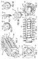
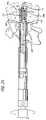
- FIG. 1is an exploded perspective view of a spinal fusion implant, radial expander of the implant, and threaded post in accordance with a preferred embodiment of the present invention for posterior insertion into the spine;
- FIG. 2is an assembled trailing end perspective view of the embodiment of FIG. 1 ;
- FIG. 3is a trailing end elevation view of the embodiment of FIG. 2 ;
- FIG. 4is a side elevation view of the embodiment of FIG. 2 ;
- FIG. 5is a leading end elevation view of the embodiment of FIG. 2 ;
- FIG. 6is a leading end elevation view of a radial expander of the implant of FIG. 1 ;
- FIG. 7is a side elevation view of the radial expander of FIG. 6 ;
- FIG. 8Ais a trailing end elevation view of the radial expander of FIG. 6 ;
- FIG. 8Bis a trailing end elevation view of a radial expander incorporating two alternative embodiments in accordance with the present invention.
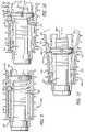
- FIG. 9is a partial side sectional view of the embodiment of FIG. 2 prior to the implant being radially expanded;
- FIG. 10is a partial side sectional view of the embodiment of FIG. 2 with the implant in partial radial expansion;
- FIG. 11is a partial side sectional view of the embodiment of FIG. 2 with the implant in a radially expanded state;
- FIG. 12is a side elevation view of one embodiment of a driver instrument for inserting the implant of FIG. 1 ;
- FIG. 13is a distal end view of the driver instrument of FIG. 12 ;
- FIG. 14is a perspective proximal end view of the funnel-shaped end of the driver instrument of FIG. 12 ;
- FIG. 15is a side elevation view of one embodiment of a rotating instrument used to rotate the threaded post to move the radial expander to radially expand the implant of FIG. 1 ;
- FIG. 16is a side elevation view of one embodiment of a plunger instrument for inserting bone growth promoting material into the implant of FIG. 1 and the disc space;
- FIG. 17is a side elevation view of the plunger instrument of FIG. 16 in an extended state
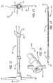
- FIG. 18is a perspective view of the posterior aspect of a lumbar segment of a spine with the dural sac retracted to the left showing a partial discectomy and an expandable guard with disc penetrating extensions approaching the disc space between the adjacent vertebral bodies with the disc penetrating extensions in an insertion position;
- FIG. 19is a side view of the guard of FIG. 18 being inserted within the spine with the disc penetrating extensions parallel to one another in the insertion position;
- FIG. 20is a side view of the guard of FIG. 18 in the deployed position with the disc penetrating extensions shown in an expanded position to induce angulation of the adjacent vertebral bodies;
- FIG. 21is a side view of the guard of FIG. 18 in the deployed position with the disc penetrating extensions in an expanded position to induce angulation of the adjacent vertebral bodies and in partial cross-section to show a side view of a drill being inserted through the guard;
- FIG. 22is a side view of the guard of FIG. 18 in partial cross-section showing the spinal fusion implant of FIG. 1 and the driver instrument of FIG. 12 passing through the guard to install the implant into a prepared implantation space across the height of the restored disc space and into the adjacent vertebral bodies;
- FIG. 23is a side view of the implant of FIG. 1 in a non-expanded state inserted into the implantation space and the rotating instrument of FIG. 15 passing through the driver instrument of FIG. 12 and guard of FIG. 18 both shown in partial cross section to engage the threaded post;
- FIG. 24is a side view of the implant of FIG. 1 radially expanded in the implantation space via the rotating instrument of FIG. 15 that passes through the driver instrument and guard both shown in partial cross section;
- FIG. 25is a side view of the rotating instrument of FIG. 15 removing the threaded post from the implant of FIG. 1 through the driver instrument and guard both shown in partial cross section;
- FIG. 25Ais an enlarged fragmentary view along line 25 A of FIG. 25 showing the cooperative engagement of the driver instrument and threaded post;
- FIG. 26is a partial side sectional view of the guard and driver instrument with the plunger instrument of FIG. 16 inserted therein and being used to fill the interior of the implant of FIG. 1 with bone growth promoting material;
- FIG. 27is a partial side sectional view of the guard and driver instrument with the instrument of FIG. 16 in an extended state inserted therein for delivering bone growth promoting material beyond the radial expander and to regions of the disc space beyond the leading end of the implant not occupied by the implant;
- FIG. 28is a partial side sectional view of the implant of FIG. 1 in an expanded state with the threaded post being partially threaded into the radial expander;
- FIG. 29is a partial side sectional view of the implant of FIG. 1 with the post partially threaded into the radial expander being advanced toward the leading end of the implant to unseat the radial expander and return the implant to the non-expanded state for posterior extraction of the implant from the implantation space;
- FIG. 30is a side elevation view of one embodiment of a remover instrument used to unlock and remove a seated radial expander from an anterior approach and through the leading end of the implant to place the implant of FIG. 1 into a non-expanded state;
- FIG. 31is a partial side sectional view of the remover instrument of FIG. 30 being used to expand the implant anteriorly to unlock and displace the expander to allow for removal of the implant;
- FIG. 32is a partial side sectional view of the implant shown in FIG. 1 in a non-expanded state with the radial expander being removed from the leading end of the implant by the remover instrument of FIG. 30 ;
- FIG. 33is an exploded perspective view of a spinal fusion implant, radial expander, and threaded post in accordance with another preferred embodiment of the present invention for anterior insertion into the spine;
- FIG. 34is a side elevation view of the embodiment of FIG. 33 ;
- FIG. 35is a leading end elevation view of the embodiment of FIG. 33 ;
- FIG. 36is a trailing end elevation view of the embodiment of FIG. 33 ;
- FIG. 37is a perspective view of an alternative embodiment of the implant and threaded post of FIG. 33 having two diametrically opposed shortened arms;
- FIG. 38is a perspective view of an alternative embodiment of the implant of FIG. 33 having arms of generally the same length;
- FIG. 39is a trailing end elevation view of the radial expander of FIG. 33 ;
- FIG. 40is a side elevation view of the radial expander of FIG. 33 ;
- FIG. 41is a leading end elevation view of the radial expander of FIG. 33 ;
- FIG. 42is a fragmentary side elevation view of the leading end of one embodiment of a driver instrument for inserting the implant of FIG. 33 ;
- FIG. 43is a side elevation view of one embodiment of an instrument for holding the implant of FIG. 33 while the radial expander of FIG. 33 is advanced through the interior of the implant;
- FIG. 44is a fragmentary side elevation view in partial cross section of one embodiment of a rotating instrument used to linearly advance the radial expander along the threaded post and into the implant to radially expand the implant of FIG. 33 ;
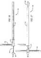
- FIG. 45is a fragmentary side elevation view in partial cross section of one embodiment of an instrument for use in removing the post from the implant of FIG. 33 ;
- FIG. 46is a side elevation view of two adjacent vertebrae and a hollow guard for use in preparing a disc space to receive the implant of FIG. 33 ;
- FIG. 47is a side elevation view of the adjacent vertebrae and guard of FIG. 46 in partial cross-section and a side view of a drill being inserted through the guard;
- FIG. 48is an exploded side view of the implant of FIG. 33 , the instrument of FIG. 42 , and an implant receiving space formed across the height of the disc space and the adjacent vertebral bodies shown in partial cross section;
- FIG. 49is a side elevation view of the implant of FIG. 33 in a non-expanded state inserted into the implant receiving space formed across the height of the disc space and two adjacent vertebral bodies in cross section and a fragmentary view of the instrument of FIG. 43 in partial cross section being positioned to engage the arms of the implant with the instrument of FIG. 44 shown in partial cross section being inserted therethrough for cooperative engagement with the post;
- FIG. 50is a side elevation view in partial cross section of the implant of FIG. 33 with the instrument of FIG. 44 in rotational engagement with the post of FIG. 33 moving the radial expander into the implant;
- FIG. 51is a side elevation view in partial cross section of the implant of FIG. 33 with the instrument of FIG. 45 being used to remove the post of FIG. 33 from the implant in the expanded state;
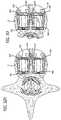
- FIG. 52Ais a top plan view in partial cross section of a vertebra with two implants of FIG. 33 in an expanded state installed side-by-side into a disc space from an anterior approach with the trailing ends in close proximity to each other and the shortened arms oriented toward the antero-lateral aspects of the vertebral body;
- FIG. 52Bis a top plan view in partial cross section of a vertebra with two implants of FIG. 33 in an expanded state installed side-by-side into a disc space from an anterior approach with the trailing ends in close proximity to each other in a toed-in orientation and the shortened arms oriented toward the antero-lateral aspects of the vertebral body;
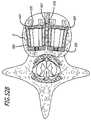
- FIG. 53is a fragmentary top plan view in partial cross section of a vertebra with two implants of FIG. 37 in an expanded state installed side-by-side into a disc space from an anterior approach with the trailing ends in closer proximity to each other than in FIG. 52A ;
- FIG. 54is a side elevation view of a preferred embodiment of a remover instrument used to remove an installed radial expander from an implant to collapse the implant of FIG. 33 into a non-expanded state;
- FIG. 55is a partial side sectional view of the implant of FIG. 33 and the instrument of FIG. 54 being used to unlock the radial expander;
- FIG. 56is a partial side sectional view of the implant of FIG. 33 with the instrument of FIG. 54 being fully deployed in the implant and a hook being used to extract the radial expander from the implant.
- FIGS. 1–11show a preferred embodiment of a radially expandable implant and threaded post used to expand the implant in accordance with the present invention.
- implant 100preferably is a spinal fusion implant adapted to be installed from at least in part a posterior approach to the spine into an implantation space formed across the height of a spinal disc and into two adjacent vertebral bodies.
- Implant 100has a body with a trailing end 102 , a leading end 104 for insertion first into the disc space, and preferably has a hollow interior 103 .
- Leading end 104is preferably open to permit access to hollow interior 103 of implant 100 through leading end 104 .
- Hollow interior 103is preferably configured to hold at least some bone growth promoting material therein.
- Implant 100includes at least upper and lower arcuate portions 106 a and 106 b adapted to be oriented toward and contact adjacent upper and lower vertebral bodies, respectively, and preferably has opposite sides 108 a and 108 b .
- Arcuate portions 106 a , 106 b and sides 108 a , 108 binclude arms 110 that extend from trailing end 102 along at least a part of the length of the implant toward leading end 104 .
- Arms 110are preferably separated by a space 112 .
- Spaces 112may be of different lengths and widths and may, for example, be in the shape of a slit, a slot, or any other shape suitable for the intended purpose of spacing apart arms 110 .
- spaces 112permit for the growth of bone from adjacent vertebral body to adjacent vertebral body through the body of implant 100 .
- arms 110have an interior surface 114 facing hollow interior 103 of implant 100 configured to bear against and hold a radial expander for forcing apart arms 110 from within hollow interior 103 .
- upper portion 106 a , lower portion 106 b , and at least one of sides 108 a , 108 bare configured to locate an expander along the length of the body of implant 100 between and away from each of trailing and leading ends 102 , 104 and to resist dislodgement of the expander when implant 100 is in use.
- Interior surface 114 of arms 110 of at least upper and lower arcuate portions 106 a , 106 bpreferably has a ramped portion 116 and seat 118 for receiving an expander 120 .
- Each arm 110preferably is of such length, thickness, and material to resist rotational torquing forces during rotation of implant 100 while being flexible enough to move in a radial direction away from the mid-longitudinal axis of implant 100 when forced apart from the interior of implant 100 .
- one embodiment of implant 100has six arms 110 , each of which flexes in a radial direction away from the mid-longitudinal axis; thus, each arm 110 moves in a direction different from that of any of the other arms 110 of implant 100 .
- each arm 110is sufficiently resilient so that each arm 110 may be moved away from the mid-longitudinal axis of implant 100 and may be permitted to return to its original orientation if desired without substantial deformation.
- preferred materials for arms 110include, but are not limited to, metals such as titanium and stainless steel, plastics, and carbon fibers among others. Arms 110 may be engineered to have a flexibility and springiness optimal for the stiffness of the area of the spine into which they are to be implanted.
- arms 110may be at least in part concave along at least a portion of the length of implant 100 .
- a concave configuration of arms 110provides a desirable springiness and resilience for contacting and supporting the vertebral bodies adjacent implant 100 .
- movable arms 110spaced around the entire circumference of the implant, the invention is not so limited.
- one or more arms 110may be truncated or omitted from a side or sides to limit the expansion of the width of the implant.
- a preferred embodiment of implant 100would have at least two arms 110 on each of upper and lower arcuate portions 106 a , 106 b , each of arms 110 being adapted to be radially expanded in a direction away from the mid-longitudinal axis of implant 100 .
- arms 110may be of different lengths.
- Implant 100preferably includes at least one external thread 122 to permit for the rotational insertion of implant 100 into the disc space and between adjacent vertebral bodies a human spine.
- the exterior of implant 100may include other bone engaging surfaces such as projections, splines, knurling, ratchets, or other surface roughenings to resist expulsion of the implant from the implantation space after implantation.
- trailing end 102preferably is configured to cooperatively engage a driver 300 shown in FIG. 12 used to install implant 100 into the disc space.
- trailing end 102may include truncated sides 124 for cooperatively engaging flanges 310 of driver 300 and recesses 126 a and 126 b for engaging pins 312 a and 312 b , respectively, of driver 300 .
- Trailing end 102 of implant 100has an opening 128 sized for receiving a post 200 for engagement with radial expander 120 .
- Post 200is configured to be inserted into implant 100 through trailing end 102 .
- Post 200preferably has a shaft 202 with at least one thread 204 and a head 206 .
- Head 206includes a tool engagement area 208 for cooperatively engaging a tool used for inserting and removing post 200 from implant 100 .
- Area 208is shown as having a hex-shaped engagement surface, but it is understood that area 208 may have any configuration suitable for its intended purpose.
- the distal end of post 200passes through opening 128 of implant 100 and extends into the interior of implant 100 to engage radial expander 120 .
- Thread 204is adapted to cooperatively engage radial expander 120 to move radial expander toward trailing end 102 of implant 100 and force arms 110 apart to expand implant 100 .
- Shaft 202may be at least in part smooth to permit movement of shaft 202 within opening 128 without engagement to opening 128 .
- radial expander 120is configured to be inserted at least in part within hollow interior 103 of implant 100 .
- Expander 120preferably has a leading face 130 adapted to be oriented toward trailing end 102 of implant 100 and an opposite trailing face 132 adapted to be oriented toward leading end 104 of implant 100 when inserted within hollow interior 103 of implant 100 .
- a preferred radial expander 120has an opening 134 , guide pegs 136 , and a rim 138 adapted to bear against interior surface 114 of arms 110 .
- Radial expander 120is preferably at least in part circular or may have any other configuration suitable for its intended purpose.
- Opening 134is preferably threaded to cooperate with thread 204 of post 200 to move radial expander 120 toward trailing end 102 of implant 100 .
- threaded rotational engagementis preferred for moving radial expander 120
- post 200may be configured to engage radial expander 120 with a retractable flange or projection and pull expander 120 into position to expand arms 110 .
- expander 120has a fixed shape.
- Guide pegs 136 of radial expander 120are adapted to fit within spaces 112 such that as post 200 is rotated, radial expander 120 advances in a linear direction away from leading end 104 towards trailing end 102 of implant 100 . Pegs 136 prevent substantial rotation of radial expander 120 during rotation of post 200 . Although two guide pegs 136 are shown extending from radial expander 120 , the number and shape of pegs 136 may be varied as suitable for their intended purpose.
- FIG. 8Bshows a radial expander 120 ′ incorporating two alternative embodiments in accordance with the present invention.
- Radial expander 120 ′is adapted to selectively expand the height of implant 100 and to limit or prevent the expansion of the width of implant 100 .
- the configuration of radial expander 120 ′provides for the selective movement of one or more arms 110 away from the mid-longitudinal axis of implant 100 as radial expander 120 ′ is advanced into implant 100 .
- radial expander 120 ′may have one or more truncated sides 135 to form a reduced width portion of radial expander 120 ′.
- Truncated side 135is preferably configured to avoid contact with the interior surface 114 of arms 110 adjacent truncated side 135 and is preferably configured to clear interior surface projections such as, for example, ramp 116 of arm 110 during the advancement of radial expander 120 ′ toward leading end 102 .
- radial expander 120 ′may include a groove 137 configured to receive at least a portion of an arm 110 adjacent thereto.
- rim 138 of radial expander 120 ′bear against the interior surface 114 of arms 110 to expand the height of implant 100 so as not to induce expansion of any arm or arms 110 adjacent truncated side 135 or groove 137 , as the case may be.
- the expansion of the implantmay be controlled by the interaction of the radial expander and arms of the implant to expand the width to only one side or to expand both sides by different amounts and involve one or more arms on a side of the implant. It is appreciated that other configurations of radial expander 120 ′ are possible to achieve its intended purpose without departing from the scope of the present invention.
- FIG. 9shows implant 100 in a collapsed state.
- post 200is rotated, causing radial expander 120 to travel within the interior of implant 100 from a position proximate leading end 104 toward trailing end 102 .
- Pegs 136travel within space 112 and can contact the sides of arms 110 to limit rotation of radial expander 120 during rotation of post 200 .
- FIG. 10shows rim 138 of radial expander 120 moved along interior surface 114 of implant 100 after post 200 is initially rotated, and shows rim 138 in contact with ramp portions 116 of implant 100 . Movement of radial expander 120 away from leading end 104 along ramp portions 116 forces arms 110 to move away from the mid-longitudinal axis of implant 100 and toward the adjacent vertebral bodies.
- FIGS. 12–14show an implant driver 300 for inserting implant 100 into a disc space.
- Implant driver 300has a shaft 302 , a distal end 304 , and a proximal end 306 .
- Shaft 302is preferably hollow and is adapted to permit the passage of other instruments therethrough as described below.
- Distal end 304includes an implant engaging head 308 with flanges 310 , pins 312 a , 312 b , and an opening 314 .
- Implant engaging head 308is sized and shaped to cooperatively engage an implant to hold and manipulate the implant during insertion into the disc space.
- Proximal end 306includes a handle 316 for rotational and linear advancement of driver 300 .
- Proximal end 306preferably has a funnel-shaped opening 318 passing through shaft 302 and expanding through distal end 304 .
- Funnel-shaped opening 318is preferably configured as shown in FIG. 14 to facilitate the introduction of bone growth promoting material into shaft 302 .
- Funnel-shaped opening 318is preferably sized and shaped to receive other instruments therethrough, such as plunger 500 described in association with FIGS. 16 and 17 below.
- FIG. 15shows a rotating tool 400 for engaging and rotating post 200 .
- Rotating tool 400has a distal end 402 and a proximal end 404 .
- Distal end 402has a tip 406 adapted to cooperatively engage area 208 of post 200 .
- tip 406is hex-shaped, but may be of any shape suitable to engage post 200 .
- Tip 406is preferably adapted to engage area 208 of post 200 such that upon the disengagement of post 200 from implant 100 , rotating tool 400 can withdraw post 200 through shaft 302 of driver 300 .
- tip 406may be adapted to cooperatively engage with area 208 , for example, via an interference fit, detent, or retractable spring flange.
- Proximal end 404is preferably configured to engage a handle and has a stop 408 .
- Proximal end 404is preferably adapted to engage with a mechanical or manual device for rotating shaft 410 .
- FIGS. 16 and 17show a plunger instrument for inserting bone growth promoting material into implant 100 and into the surrounding disc space.
- Plunger 500preferably has an outer shaft 502 , an inner rod 504 , and a handle 506 .
- Inner rod 504preferably has a proximal end configured to engage a handle, such as a T-handle for example, and a stop 508 for limiting the travel of inner rod 504 when placed within outer shaft 502 .
- plunger 500may be inserted into an instrument adapted to deliver bone growth promoting material into implant 100 such as driver 300 .
- Plunger 500 and driver 300 togethermay be placed within a guard such as guard 600 of FIG. 18 to introduce bone growth promoting material into hollow interior 103 of implant 100 and preferably the disc space surrounding the implant.
- bone growth promoting materialis introduced into hollow interior 103 of shaft 302 of driver 300 through funnel-shaped opening 318 .
- Plunger 500 with inner rod 504 inserted thereinmay be inserted into the interior of driver 300 to push bone growth promoting material therethrough and into the implant. Plunger 500 and inner rod 504 may further move bone growth promoting material into the remaining areas inside and around the implant not yet filled with bone growth promoting material.
- Plunger 500preferably has a clamp 510 and stop 508 to limit the extension of inner rod 504 from outer shaft 502 .
- Stop 508may have any configuration adapted to limit the travel of inner rod 504 , for example, a shoulder, flange, or other projection.
- inner rod 504is solid, the invention is not so limited.
- Clamp 510 in the tightened positionholds inner rod 504 in fixed relationship to outer shaft 502 and preferably so as not to extend from the distal end of shaft 502 . When clamp 510 is released, inner rod 504 is permitted to travel beyond the distal end of outer shaft 502 to the extent limited by stop 508 .
- FIGS. 18–30show various steps of a preferred method for inserting implant 100 and using associated instrumentation disclosed herein.
- FIG. 18is a perspective view of a segment of a spine viewed from a posterior aspect with the dural sac retracted to the left showing that a partial discectomy has already been performed.
- Guard 600with disc penetrating extensions 602 , 604 and window 606 , is shown approaching the disc space between the adjacent vertebral bodies with disc penetrating extensions 602 , 604 in a first or insertion position.
- guardsmay be used to provide protected access to the disc space including, but not limited to, those taught by Michelson in application Ser. Nos. 10/085,731 and 10/085,406; and U.S. Pat. Nos. 5,015,247; 5,484,437; 6,080,155; and 6,210,412 all of which are incorporated herein by reference.
- An impaction cap 608is positioned on the proximal end of guard 600 to maintain it in the open position such that the disc penetrating extensions are closed into the insertion position. In this position, guard 600 is ready to be placed or driven into the disc space between the adjacent vertebral bodies.
- guard 600rotationally articulates to permit movement of disc penetrating extensions 602 , 604 in response to movement of a first portion 610 and a second portion 612 relative to one another.
- the rotational articulationpreferably occurs about a hinge 614 , which is preferably formed in first and second portions 610 , 612 .
- guard 600is shown in a closed position with the disc penetrating extensions shown in the inserted position to induce lordosis to the vertebral bodies.
- the proximal endhas a lock collar 616 placed around it to maintain guard 600 in the closed position.
- guard 600is in a closed position with disc penetrating extensions 602 , 604 in the inserted position to induce angulation to the adjacent vertebral bodies.
- a bone removal devicesuch as a drill 700 being inserted through guard 600 .
- Other bone removal devicessuitable for the intended purpose such as, but not limited to, burrs, reamers, mills, saws, trephines, chisels, and the like may also be used and would be within the scope of the present invention.
- Guard 600provides protected access to the disc space and the adjacent vertebral bodies for drill 700 via the elongated opening in guard 600 .
- Drill 700may have a reduced diameter-cutting portion relative to the shaft diameter of guard 600 or may be inserted through an inner sleeve that passes into guard 600 to guide drill 700 to form an implantation space smaller than the passage through guard 600 .
- the guard openingmay be taller than the height of the cutting portion of drill 700 .
- Such a taller openingalso allows the implantation of an implant taller than the height of the cutting portion of drill 700 .
- implant 100 and implant driver 300may be passed through guard 600 to insert implant 100 in a collapsed position into the disc space between the adjacent vertebral bodies.
- the guardmay be left in place throughout the procedure.
- Implant 100is assembled with post 200 inserted through trailing end 102 of implant 100 to engage radial expander 120 inserted in the collapsed position into hollow interior 103 of implant 100 through leading end 104 .
- Radial expander 120 in this positionmay bear against the interior surface 114 of arms 110 but does not yet force arms 110 apart so that implant 100 is in a non-expanded state.
- Implant 100is preferably rotated into the disc space such that thread 122 penetrably engages the bone of the adjacent vertebral bodies.
- rotating tool 400is used to engage and rotate post 200 so as to pull radial expander 120 away from leading end 104 and toward trailing end 102 along the interior surface 114 of arms 110 to transition implant 100 from a collapsed position to an expanded position.
- FIG. 24As shown in FIG. 24 , as rotating tool 400 is rotated, radial expander 120 moves toward trailing end 102 of implant 100 causing arms 110 to move radially outward away from the mid-longitudinal axis of implant 100 .
- the interaction between radial expander 120 and arms 110is best shown in FIGS. 9–11 .
- the radial expansion of implant 100results in a greater implant height and width proximate leading end 104 than the implant height and width proximate trailing end 102 .
- Upper and lower arcuate portions 106 a , 106 bare positioned in angular relationship to each other and position the vertebral bodies adjacent implant 100 in an angular relationship to each other.
- Rotating tool 400is adapted to cooperatively engage tool engagement area 208 of post 200 .
- the leading end of rotating tool 400may be tapered to allow the tip of tool 400 to slightly bind and positively engage tool engagement area 208 .
- Radial expander 120remains seated within hollow interior 103 of implant 100 to hold arms 110 in a radially expanded state.
- FIGS. 26 and 27show a preferred method for insertion of bone growth promoting materials into implant 100 and the disc space surrounding implant 100 .
- Driver 300is shown inserted into guard 600 with its distal end adjacent to and in communication with opening 128 of implant 100 to access hollow interior 103 of implant 100 .
- Bone growth materialis introduced into funnel shaped end 318 of driver 300 .
- Plunger 500 with inner rod 504 in the retracted positionis used to push and load the bone growth promoting material through shaft 302 of driver 300 and into implant 100 .
- Sufficient bone growth promoting materialis introduced into driver 300 to at least partially fill implant 100 .
- the implantmay be pre-loaded with bone growth promoting material prior to its insertion into the implantation space. Additional bone growth material may be added to fill any space within the implant created as a result of transitioning implant 100 to an expanded position as described below.
- inner rod 504is moved forward in the extended position into implant 100 through opening 128 of trailing end 102 to push the bone growth promoting material in its path through opening 134 of radial expander 120 . Distributing bone growth promoting material beyond radial expander 120 fills the interior of implant 100 proximate leading end 104 and introduces bone growth promoting material further into the disc space beyond leading end 104 and unoccupied by implant 100 . After inner rod 504 is retracted from within the interior of implant 100 and plunger 500 is removed from driver 300 , additional bone growth promoting material may be inserted into driver 300 .
- Plunger 500then may be used to fill the space left unoccupied by the removal of inner rod 504 with bone growth promoting material and further pack bone growth promoting material into implant 100 .
- plunger 500 and driver 300are removed from guard 600 .
- the trailing end of guard 600is then opened to return disc penetrating extensions 602 , 604 to the closed position to facilitate the removal of guard 600 from the disc space.
- FIGS. 28–32show a preferred remover and methods of disengaging radial expander 120 from seat 118 of implant 100 if it is desired to uninstall implant 100 or other implants of the present invention designed for a generally posterior insertion.
- FIG. 28shows post 200 being partially threaded into a seated radial expander 120 by rotating tool 400 such that a portion of post 200 extends from trailing end 102 of implant 100 .
- post 200may then be advanced in a linear direction without substantial rotation toward leading end 104 of implant 100 such as, for example, with an impaction force. The linear advancement of post 200 toward leading end 104 moves expander 120 out of seat 118 and toward leading end 104 .
- implant armsto collapse inward to the unexpanded state, thereafter allowing the implant to be unthreaded or otherwise removed from the spine.
- the implant holdermay be attached prior to collapsing the implant or thereafter. With expander 120 removed from the interior of implant 100 , arms 110 are no longer held in a radially expanded position, thereby causing implant 100 to collapse to an unexpanded state.
- FIG. 30shows a remover 800 for removing radial expander 120 from hollow interior 103 of implant 100 through leading end 104 .
- Remover 800has a shaft 802 , a distal end 804 , and a proximal end 806 .
- Distal end 804has a threaded rod 808 and an enlarged head 810 with a diameter configured to enter hollow interior 103 of implant 100 in a radially expanded state and force apart arms 110 .
- Proximal end 806is preferably configured to be attached to a removable handle for rotating remover 800 .
- Threaded rod 808 of remover 800threads into radial expander 120 causing forward movement of remover 800 toward leading end 104 of implant 100 .
- enlarged head 810contacts interior surface 114 of arms 110 , forcing arms 110 to move outward and further away from the mid-longitudinal axis of implant 100 .
- This movementin turn causes seat 118 to expand outward opening the entrance to seat 118 , thus permitting radial expander 120 to be removed from seat 118 of implant 100 .
- FIG. 32shows remover 800 removing radial expander 120 from seat 118 to return arms 110 to their initial non-expanded position. The implant may then be removed from the implantation site if desired.
- FIGS. 33–56show various embodiments of an implant 900 for insertion from at least in part an anterior approach to the spine as well as instruments and the associated method for inserting and removing implant 900 .
- Implant 900is similar to implant 100 , with certain differences noted below. As shown in FIGS. 33–36 , implant 900 has an open trailing end 902 , a leading end 904 shown closed in this embodiment, a base 905 proximate the leading end, and a shortened arm 909 and lengthened arms 910 extending from base 905 .
- FIG. 37shows an alternative embodiment of implant 900 having two opposed shortened arms 909 and lengthened arms 910 .
- Shortened arms 909are preferably located on at least one side of implant 900 when two implants are inserted side-by-side as shown in FIGS. 52A , 52 B, and 53 . Shortened arms 909 provide for a reduced diameter of trailing end 902 such that trailing end 902 does not substantially protrude from the disc space to minimize the risk of interference with delicate vascular and neurological structures present adjacent to the disc space. Shortened arms 909 also permit two implants 900 in an expanded state to be placed side-by-side in close proximity to each other in the disc space. Although a combination of shortened arms 909 and lengthened arms 910 is preferred, the invention is not so limited. For example, in situations where the surgeon determines it is appropriate, implant 900 may have arms 910 of generally equal length as shown in another alternative embodiment of implant 900 in FIG. 38 .
- shortened arms 909have a notched area 917 that functions to hold the radial expander 920 in seat 918 and maintain shortened arms 909 in a radially expanded state when radial expander 920 is seated in seats 918 of lengthened arms 910 .
- a post 1000is inserted through the trailing end 902 .
- Leading end 904preferably has a threaded opening 928 for threadably engaging post 1000 .
- Post 1000has a shaft 1002 with a first thread 1004 for cooperative engagement with a tool 1300 shown in FIG. 44 for pushing or otherwise moving radial expander 920 away from trailing end 902 and toward base 905 proximate leading end 904 of implant 900 .
- Post 1000has a head 1006 with a tool engagement area 1008 that is preferably hex-shaped to engage a post remover 1400 shown in FIG. 45 , and a second thread 1010 shown in FIGS. 50 , 51 at the end opposite head 1006 for cooperative engagement with threaded opening 928 in leading end 904 of implant 900 .
- a postmay be used having a leading end with a retractable flange or other projection for cooperative engagement with the leading end of the implant. Such a post may then be used to rotate the radial expander into position in a fashion similar to that described with reference to FIGS. 23 and 24 . Once the radial expander is seated, the flanges or other projections may be retracted , and the post may then be withdrawn.
- radial expander 920is similar to radial expander 120 shown in FIGS. 6–8 . Opening 934 of radial expander 920 is preferably unthreaded. A threaded opening is not essential since radial expander 920 is moved by rotating tool 1300 and not by post 1000 , described in more detail below.
- FIG. 42shows an implant driver 1100 for inserting implant 900 into a disc space.
- Driver 1100has a shaft 1102 and a distal end 1104 .
- Distal end 1104preferably has an implant engaging head 1108 with flanges 1110 spaced apart by recessed areas and a bore 1120 .
- Implant engaging head 1108is preferably sized and shaped to cooperatively engage trailing end 902 of implant 900 for insertion into the disc space.
- Implant engaging head 1108preferably is tapered to facilitate insertion into the interior of implant 900 and to facilitate the placement of flanges 1110 into spaces 912 .
- Arms 909 , 910fit into recessed areas between flanges 1110 . In this position, driver 1100 is engaged to implant 900 and can rotate implant 900 .
- Bore 1120is preferably configured to receive post 1000 so that driver 1100 may insert implant 900 with post 1000 already attached thereto.
- FIG. 43shows an implant holder 1200 for holding implant 900 in a stable position while one or more tools, for example rotating tool 1300 , engages with post 1000 to move radial expander 920 toward leading end 904 .
- Implant holder 1200has a distal end 1202 , a proximal end 1204 , a shaft 1206 therebetween, and a handle 1208 .
- Distal end 1202preferably has a plurality of flanges 1210 that are configured for engagement with spaces 912 between arms 909 , 910 .
- Shaft 1206is preferably hollow and sized to accommodate the passage of tools therethrough, for example, rotating tool 1300 .
- Flanges 1210are adapted to fit in spaces 912 between arms 909 , 910 to hold implant 900 .
- Rotating tool 1300is used to rotate post 1000 to move radial expander 920 while implant 900 is held stable by holder 1200 to resist the rotational forces bearing upon post 1000 .
- FIG. 44shows rotating tool 1300 for advancing radial expander 920 away from trailing end 902 and toward base 905 proximate leading end 904 .
- Rotating tool 1300has a distal end 1302 and a shaft 1310 .
- Distal end 1302has a bore 1312 with a thread 1314 adapted to cooperatively engage with first thread 1004 of post 1000 .
- Bore 1312preferably has an unthreaded portion at its leading end that permits rotating tool 1300 to move over a portion of post 1000 such as post head 1006 prior to engagement of the thread.
- distal end 1302bears against radial expander 920 to advance radial expander 920 into implant 900 .
- rotating tool 1300is unthreaded from post 1000 and removed from implant 900 .
- FIG. 45shows a post remover 1400 for removing post 1000 after radial expander 920 has been seated in seat 918 of implant 900 .
- Post remover 1400has a shaft 1402 and a distal end 1404 .
- Distal end 1404has a bore 1406 with a post engagement surface 1408 that is preferably hex-shaped to cooperatively engage with tool engagement area 1008 of post 1000 .
- Post remover 1400removes post 1000 from implant 900 by unthreading post 1000 from opening 928 in leading end 904 of implant 900 .
- FIGS. 46–51show various steps of a preferred method for inserting implant 900 from an anterior approach to the spine and using associated instrumentation disclosed herein.
- FIGS. 46 and 47show insertion of a guard 1600 with disc penetrating extensions 1602 into the disc space and the use of drill 700 to prepare the disc space for implantation.
- Disc penetrating extensions 1602need not be but are preferably angled to place the adjacent vertebral bodies in angular relationship to each other.
- the guardmay have one or more extensions of any size or shape suitable for the intended purpose and one or more bores which could, but need not, be in part overlapping. It is understood that the use of such a guard is only preferred and not required.
- the guardmay be of any type suitable for the purpose of providing protected access while the disc space is prepared and during implantation including, but not limited to, the guards incorporated by reference above.
- implant 900is rotatably inserted so that thread 922 penetrably engages the bone of the adjacent vertebral bodies.
- guard 1600may be left in place throughout the whole procedure, the procedure then being carried out through the hollow shaft of guard 1600 .
- implant 900may be installed without first installing post 1000 into implant 900 . However, it is preferred that post 1000 is installed in implant 900 before implant 900 is installed into the disc space.
- radial expander 920is moved onto post 1000 and implant holder 1200 is moved into position.
- rotating tool 1300is inserted through the interior of shaft 1206 so that threaded bore 1302 of rotating tool 1300 cooperatively engages first thread 1004 of post 1000 .
- FIG. 49As illustrated in FIG. 49 , radial expander 920 is moved onto post 1000 and implant holder 1200 is moved into position. After flanges 1210 of implant holder 1200 are engaged with arms 909 , 910 of implant 900 , rotating tool 1300 is inserted through the interior of shaft 1206 so that threaded bore 1302 of rotating tool 1300 cooperatively engages first thread 1004 of post 1000 . As shown in FIG.
- post remover 1400is used to engage head 1006 of post 1000 .
- Rotating post remover 1400disengages post 1000 from threaded opening 928 of implant 900 , allowing post 1000 to be withdrawn through opening 934 of radial expander 920 and from the interior of the implant.
- FIGS. 52A , 52 B, and 53show two implants 900 in a radially expanded state placed in close proximity to one another within the perimeter of a disc space D.
- implants 900 of FIG. 33are preferably positioned such that shortened arms 909 face the antero-lateral aspect of the vertebral bodies such that the structure of each implant is kept substantially within the disc space to minimize the risk of interference with delicate vascular and neurological structures present adjacent to the disc space.
- implants 900are oriented toward each other in a toed-in configuration permitting the implants to be closer to each other in a side-by-side placement. Such placement permits the use of larger implants to better fill the disc space than may be possible with implants positioned parallel to each other.
- two implants 900 of FIG. 37are preferably placed such that the mid-longitudinal axis of each implant are in closer proximity to one another than the embodiment shown in FIG. 52A . Closer placement is made possible, by way of example only, by positioning each implant such that shortened arms 909 face each other within the disc space. Additionally, the size of thread 922 may be reduced towards trailing end 902 so that trailing end 902 has a reduced thread portion 923 to minimize contact with the thread of an adjacent implant. Such an orientation permits greater expansion to occur without a lengthened arm from one implant crossing the lengthened arm of an implant adjacent thereto. In all the embodiments described herein, it should be apparent that a number of arrangements of shortened and/or lengthened arms are possible and all within the broad scope of the present invention.
- FIGS. 54–56show a preferred remover and methods of disengaging radial expander 920 from seat 918 of implant 900 if it is desired to uninstall implant 900 .
- FIG. 54shows a remover 1500 for removing radial expander 920 from hollow interior 903 of implant 900 through trailing end 902 .
- Remover 1500has a shaft 1502 and a distal end 1504 .
- Distal end 1504has a bore 1514 with a thread 1516 that is configured for cooperative engagement with first thread 1004 of post 1000 , a collar 1518 with an outer diameter slightly smaller than the diameter of hollow interior 903 of implant 900 in a radially expanded state, and a bearing 1520 that allows remover 1500 to rotate relative to collar 1518 .
- Bore 1514preferably has an unthreaded portion at its leading end that permits remover 1500 to move over a portion of post 1000 prior to rotational engagement.
- FIG. 56shows an instrument, for example a hook 1700 , for removing radial expander 920 from implant 900 to return arms 909 , 910 to their initial or non-expanded position.
- the implants described hereinpreferably have a generally circular cross section transverse to the mid-longitudinal axis of the implant.
- the implantsIn the collapsed position, the implants may have a generally cylindrical configuration or may be in the shape of a cylinder with at least a portion of a side removed.
- the implantsmay be tapered from trailing end to leading end and may have a generally frusto-conical configuration in the collapsed position to facilitate insertion into the implantation space.
- the implants described hereinin the expanded position, may have a leading end or a trailing end tapered at an angle that matches the angle of the upper, lower, and side portions in the expanded position.
- the radially expandable spinal fusion implantmay include, be made of, treated, coated, filled, used in combination with, or have a hollow for containing artificial or naturally occurring materials and/or substances suitable for implantation in the human spine.
- materials and/or substancesinclude any source of osteogenesis, bone growth promoting materials, bone, bone derived substances or products, demineralized bone matrix, ossifying proteins, bone morphogenetic proteins, hydroxyapatite, genes coding for the production of bone, and bone including, but not limited to, cortical bone.
- the implantcan also be formed of an artificial material stronger than bone such as metal including, but not limited to, titanium and its alloys, surgical grade plastics, plastic composites, ceramics, or other materials suitable for use as a spinal fusion implant.
- the implantcan include at least in part of materials that are bioabsorbable and/or resorbable in the body such as bone and/or bone growth promoting materials.
- the implant of the present inventioncan be formed of a porous material or can be formed of a material that intrinsically participates in the growth of bone from one of adjacent vertebral bodies to the other of adjacent vertebral bodies. Where such implants are for posterior implantation, the trailing ends of such implants may be treated with, coated with, or used in combination with chemical substances to inhibit scar tissue formation in the spinal canal.
- the implants of the present inventionmay be adapted to facilitate the electrostimulation of the fusion area into which they are inserted and the proximate bone thereabout.
- the implant of the present inventionmay be modified, or used in combination with materials to make it antibacterial, such as, but not limited to, electroplating or plasma spraying with silver ions or other substance. At least a portion of the implant may be treated to promote bone ingrowth between the implant and the adjacent vertebral bodies.
- the implant of the present inventionmay be used in combination with spinal fixation hardware, bone screws, plates, rods, tethers of synthetic chords or wires.
Landscapes
- Health & Medical Sciences (AREA)
- Engineering & Computer Science (AREA)
- Biomedical Technology (AREA)
- Orthopedic Medicine & Surgery (AREA)
- Transplantation (AREA)
- Neurology (AREA)
- Heart & Thoracic Surgery (AREA)
- Oral & Maxillofacial Surgery (AREA)
- Cardiology (AREA)
- Vascular Medicine (AREA)
- Life Sciences & Earth Sciences (AREA)
- Animal Behavior & Ethology (AREA)
- General Health & Medical Sciences (AREA)
- Public Health (AREA)
- Veterinary Medicine (AREA)
- Physical Education & Sports Medicine (AREA)
- Prostheses (AREA)
Abstract
Description
This application claims priority to provisional application No. 60/279,205, filed Mar. 27, 2001, and provisional application Ser. No. 60/281,714, filed Apr. 4, 2001, both of which are incorporated by reference herein.
1. Field of the Invention
The present invention relates generally to interbody spinal implants, and instruments and methods for inserting interbody spinal implants into an implantation space in the spine, and in particular to an expandable interbody (for placement at least in part between adjacent vertebral bodies in the space previously occupied by disc material) spinal fusion implants for the immobilization of adjacent vertebrae.
2. Description of the Related Art
Expandable spinal fusion implants have height raising capabilities that are utilized once the implant is initially positioned. Such height raising capability may be utilized within the spine anteriorly, posteriorly, or both and to various extents, respectively to raise the front or back of the implant. More particularly, such implants have upper and lower surfaces of upper and lower portions that in an insertion position are collapsed relative to one another and in a deployed position are spaced further away from one another than in the collapsed position.
Expandable fusion implants offer the advantage of allowing for the placement of a potentially larger implant through a smaller opening in a patient's body. The first expandable spinal fusion (allowing for the growth of bone from vertebral body to vertebral body through the implant) implant was invented by Michelson and also is disclosed in U.S. Pat. No. 5,776,199, filed Jun. 28, 1988, which is hereby incorporated by reference herein.
Expandable interbody spinal fusion implants preferably may be inserted from an anterior approach to the spine, an approach posterior to the vertebral transverse processes, or to either side of the spinal midline in pairs. Such expandable implants are adapted to increase in height at their leading ends or at their trailing ends from a collapsed state to an expanded state for the purpose of increasing spinal lordosis at that interspace. During installation of expandable interbody spinal fusion implants, it is desirable that the surgeon have the ability to precisely control the implant with the appropriate instruments and methods to load the implant with appropriate bone growth promoting material, to insert the implant into the implantation space, to deploy the implant to a final expanded state, and to further load the implant with bone growth material if so desired.
Also known in the art are expandable interbody spinal fusion implants that are circumferentially expandable at one of their leading or trailing ends to expand both the height and the width of the implant. Such implants have an expansion mechanism that is moved from the trailing end through the interior of the implant to reach the leading end to expand the implant. Any bone growth material present within the interior of the implant would be forced out of the interior of the implant by the expansion mechanism passing therethrough. Accordingly, such implants cannot be effectively preloaded with bone growth promoting material prior to expansion of the implant.
There exists a need for a circumferentially expanding implant that is substantially hollow and substantially devoid of any elaborate or substantial space occupying expansion mechanism to permit preloading of the implant with bone growth promoting material prior to expansion of the implant. The expansion mechanism would not interfere with the capacity to compressively load osteogenic material such as bone or any other suitable material through the length of the implant and to have it extrude from the implant. The extrusion of the osteogenic material from the implant provides an increased volume of osteogenic material over a greater surface area of the adjacent vertebral bodies adjacent the disc space to be fused and beyond the surface area of contact of the implant to the vertebral bodies themselves. Surrounding the implant itself with additional fusion promoting substances in contact with the adjacent vertebral bodies may enhance the fusion process.
There also exists a need for instruments and methods for use with expandable interbody spinal fusion implants providing for all of the aforementioned needs individually or in combination.
Additional objects and advantages of the invention will be set forth in part in the description which follows, and in part will be obvious from the description, or may be learned by practice of the invention. The objects and advantages of the invention will be realized and attained by means of the elements and combinations particularly pointed out in the appended claims.
The present invention is directed to an interbody spinal fusion implant particularly adapted for anterior, posterior, and posterior lateral interbody spinal fusion; and methods and instrumentation for a preferred insertion of these implants.
The present invention implant is adapted to have a generally constant size at one end while allowing for a generally circumferential increase in size at the opposite end. This feature is particularly useful for posterior lumbar interbody fusion and posterior lateral interbody spinal fusion, where it is desirable to have the vertebral bodies spaced apart more anteriorly than posteriorly to restore the lumbar lordosis. The implant is preferably inserted in a generally cylindrical form or more particularly with the opposed surfaces of the implant adapted to contact each of the opposed adjacent vertebral bodies adjacent to the disc space to be fused being generally parallel. Subsequently, the implant is expanded at the leading end so that the opposed vertebral body engaging surfaces of the implant are then in a generally angular relationship to each other over a substantial portion of the length of the implants. The present invention methods and instrumentation in conjunction with the present invention implant allows for the installation of an implant that in its final implanted form is substantially hollow with the exception of an expander ring which is itself preferably hollow so as to not interfere with the full loading of the implant and the extrusion there through of the selected osteogenic material.
In accordance with the purposes of the present invention, as embodied and broadly described herein, an interbody spinal fusion implant is provided for implantation from at least in part a posterior approach at least in part within and across the height of a disc space between two adjacent vertebral bodies of an adult human spine. The implant includes a body having a leading end for insertion first into the disc space, a trailing end opposite the leading end, and a mid-longitudinal axis along the length of the body. The body has an upper portion adapted to contact one of the adjacent vertebral bodies, a lower portion opposite the upper portion adapted to contact another one of the adjacent vertebral bodies, and at least one side portion between the upper and lower portions. Each of the upper, lower, and side portions extend from the trailing end of the body and are spaced apart from one another to form a hollow interior therebetween. The hollow interior is configured to hold at least some bone growth promoting material therein. The upper and lower portions are configured to permit for the growth of bone from adjacent vertebral body to adjacent vertebral body through the body of the implant. Each of the upper, lower, and side portions are configured to move at least in part in a direction away from the mid-longitudinal axis of the body to allow for expansion of the height and at least a portion of the width of the body. The upper, lower, and side portions have a collapsed position relative to one another allowing for a collapsed height and width of the body, and an expanded position relative to one another allowing for an expanded height and width of the body. The expanded height and width of the body is greater than the collapsed height and width of the body, respectively.
The implant also includes an expander positioned at least in part within the hollow interior. The expander is configured to cooperatively engage an instrument adapted to be inserted through the trailing end of the body to engage and to move the expander from a position proximate the leading end when the body is in the collapsed position away from the leading end toward the trailing end of the body to place the body in the expanded position. The expander is adapted to contact and to move the upper, lower, and side portions away from the mid-longitudinal axis of the body. The upper, lower, and side portions of the body are adapted to cooperatively engage the expander to locate the expander at a location along the length of the body between and away from each of the leading and trailing ends and to resist dislodgment of the expander from that location when the implant is in use. The expander is adapted to hold at least a portion of the upper, lower, and side portions apart so as to maintain the expanded height and width of the body and to resist the collapse of the body to the collapsed body height and width when the body is in the expanded position.
In accordance with the purposes of a further embodiment of the present invention, as embodied and broadly described herein, an interbody spinal fusion implant is provided for implantation from at least in part an anterior approach at least in part within and across the height of a disc space between two adjacent vertebral bodies of an adult human spine. The body has a base proximate the leading end, an upper portion adapted to contact one of the adjacent vertebral bodies, a lower portion opposite the upper portion adapted to contact another one of the adjacent vertebral bodies, and at least one side portion between the upper and lower portions. Each of the upper, lower, and side portions extend from the base of the body and are spaced apart from one another to form a hollow interior therebetween. Each of the upper, lower, and side portions are configured to move at least in part in a direction away from the mid-longitudinal axis of the body to allow for expansion of the height and at least a portion of the width of the body. The upper, lower, and side portions have a collapsed position relative to one another allowing for a collapsed height and width of the body, and an expanded position relative to one another allowing for an expanded height and width of the body. The expanded height and width of the body is greater than the collapsed height and width of the body, respectively.
The implant also includes an expander at least in part within the hollow interior. The expander is configured to contact an instrument that is adapted to be inserted through the trailing end of the body to move the expander from a position proximate the trailing end when the body is in the collapsed position away from the trailing end and toward the base of the body to place the body in the expanded position. The expander is adapted to contact and to move the upper, lower, and side portions away from the mid-longitudinal axis of the body. The upper, lower, and side portions of the body are adapted to cooperatively engage the expander to locate the expander at a location along the length of the body between and away from each of the leading and trailing ends and to resist dislodgment of the expander from that location when the implant is in use. The expander is adapted to hold at least a portion of the upper, lower, and side portions apart so as to maintain the expanded height and width of the body and to resist the collapse of the body to the collapsed body height and width when the body is in the expanded position.
In accordance with the purposes of a further embodiment of the present invention, as embodied and broadly described herein, a method of this invention is provided for inserting an interbody spinal fusion implant from at least in part a posterior approach at least in part within and across the height of a disc space between two adjacent vertebral bodies of an adult human spine. The method includes providing the spinal implant having a body with a leading end for insertion first into the disc space, a trailing end opposite the leading end, a mid-longitudinal axis, upper and lower portions, and at least one side portion. Each of the upper, lower, and side portions extend from the trailing end of the body. A hollow interior is between the upper and lower portions. The implant includes an expander for expanding the height and at least a portion of the width of the body. The method includes preparing an implantation space to receive the implant from a posterior approach to the spine; inserting the implant at least in part into the implantation space; and moving the expander from a position proximate the leading end toward the trailing end of the body along at least a portion of the length of the body of the implant to move the upper, lower, and side portions in a direction away from the mid-longitudinal axis of the body of the implant to expand the height and at least a portion of the width of the body of the implant.
In accordance with the purposes of a further embodiment of the present invention, as embodied and broadly described herein, a method of this invention is provided for inserting an interbody spinal fusion implant from at least in part an anterior approach at least in part within and across the height of a disc space between two adjacent vertebral bodies of an adult human spine. The method includes providing the spinal implant having a body with a leading end for insertion first into the disc space, a trailing end opposite the leading end, a mid-longitudinal axis, upper and lower portions, and at least one side portion. Each of the upper, lower, and side portions extend from the leading end of the body. A hollow interior is between the upper and lower portions. The implant includes an expander for expanding the height and at least a portion of the width of the body. The method includes preparing an implantation space to receive the implant from an anterior approach to the spine; inserting the implant at least in part into the implantation space; and moving the expander from a position proximate the trailing end toward the leading end of the body along at least a portion of the length of the body of the implant to move the upper, lower, and side portions in a direction away from the mid-longitudinal axis of the body of the implant to expand the height and at least a portion of the width of the body of the implant.
In accordance with the purposes of a further embodiment of the present invention, as embodied and broadly described herein, an apparatus is provided for inserting at least in part within and across the height of a disc space between two adjacent vertebral bodies of the human spine a spinal implant having upper and lower portions, and an expander for expanding the height and at least a portion of the width of the implant from a collapsed position to an expanded position. The apparatus includes an inserter guide having a leading end and a trailing end. The leading end of the inserter guide is configured to cooperatively engage the trailing end of the implant. The inserter guide has a hollow interior forming a passage from the trailing end to the leading end through the inserter guide. The apparatus also includes a post adapted to be inserted at least in part through the trailing end of the implant and into a hollow interior of the implant for moving the expander along at least a portion of the length of the implant between the upper and lower portions of the implant. The post has a leading end configured to cooperatively engage the expander and a trailing end adapted to be coupled to the implant and cooperatively engage an instrument for moving the post. The apparatus also includes an inner shaft that is configured to be inserted at least in part within the passage of the inserter guide. The inner shaft has a leading end and a trailing end. The leading end of the inner shaft is configured to cooperatively engage the trailing end of the post. The inner shaft is adapted to move the post so as to move the expander toward the trailing end of the implant to expand the height and at least a portion of the width of the implant.
In accordance with the purposes of a further embodiment of the present invention, as embodied and broadly described herein, an apparatus is provided for use with a spinal implant having an expander for expanding the height of the implant from a collapsed position to an expanded position. The implant has a leading end for insertion first into a disc space between two adjacent vertebral bodies of the human spine and a trailing end opposite the leading end. The implant has at least upper and lower portions adapted to be moved away from one another by the expander when positioned therebetween. The apparatus includes an elongated shaft having a leading end and a trailing end opposite the leading end, and a mid-longitudinal axis. The apparatus also includes an enlarged head proximate the leading end of the shaft that is configured to be inserted at least in part between the upper and lower portions of the implant. The enlarged head is adapted to move apart the upper and lower portions to release the expander therebetween. The apparatus also includes a projection extending from the enlarged head that is adapted to cooperatively engage the expander for removal of the expander from within the implant.
In accordance with the purposes of a further embodiment of the present invention, as embodied and broadly described herein, an apparatus is provided for inserting at least in part within and across the height of a disc space between two adjacent vertebral bodies of the human spine a spinal implant having an expander for expanding the height and at least a portion of the width of the implant from a collapsed position to an expanded position. The implant has upper, lower, and side portions including a plurality of arms separated by spaces. The apparatus includes an inserter having a leading end and a trailing end opposite the leading end. The leading end of the inserter guide has a plurality of spaced apart portions that are configured to fit in the spaces between the arms of the spinal implant to cooperatively engage the inserter to the implant.
In accordance with the purposes of yet a further embodiment of the present invention, as embodied and broadly described herein, an apparatus is provided for holding a spinal implant having an expander for expanding the height and at least a portion of the width of the implant from a collapsed position to an expanded position. The implant has upper, lower, and side portions comprising a plurality of arms separated by spaces. The apparatus includes a sleeve having a leading end and a trailing end and a passageway from the trailing end to the leading end. The passageway provides access to the implant through the sleeve. The leading end of the sleeve has a plurality of spaced apart portions that are configured to fit in the spaces between the arms of the spinal implant to cooperatively engage the sleeve to the implant.
In accordance with the purposes of a further embodiment of the present invention, as embodied and broadly described herein, an apparatus is provided for use with a spinal implant having an expander for expanding the height of the implant from a collapsed position to an expanded position. The implant has a leading end for insertion first into a disc space between two adjacent vertebral bodies of the human spine and a trailing end opposite the leading end. The implant has at least upper and lower portions adapted to be moved away from one another by the expander when positioned therebetween. The apparatus includes an elongated shaft having a mid-longitudinal axis, a leading end, and a trailing end opposite the leading end. The leading end has a bore therein and an enlarged head with a collar in movable relationship to the head that permits rotational movement of the head independent of the collar. The collar and the head are configured to be inserted at least in part between the upper and lower portions of the implant. The collar is adapted to bear against and move apart the upper and lower portions of the implant to release the expander therebetween. The apparatus also includes a post that is adapted to be inserted at least in part through the trailing end of the spinal implant for guiding the elongated shaft along the mid-longitudinal axis between the upper and lower portions of the implant. The post has a leading end configured to cooperatively engage the implant and a trailing end that is adapted to be received within the bore of the elongated shaft. The head of the elongated shafted is adapted to rotate about the post.
It is to be understood that both the foregoing general description and the following detailed description are exemplary and explanatory only and are not restrictive of the invention, as claimed.
The accompanying drawings, which are incorporated in and constitute a part of this specification, illustrate the embodiments of the invention and together with the description, serve to explain the principles of the invention.
The following description is intended to be representative only and not limiting and many variations can be anticipated according to these teachings, which are included within the scope of this inventive teaching. Reference will now be made in detail to the preferred embodiments of this invention, examples of which are illustrated in the accompanying drawings.
As best shown inFIGS. 9–11 ,arms 110 have aninterior surface 114 facinghollow interior 103 ofimplant 100 configured to bear against and hold a radial expander for forcing apartarms 110 from withinhollow interior 103. Preferably,upper portion 106a,lower portion 106b, and at least one ofsides implant 100 between and away from each of trailing and leading ends102,104 and to resist dislodgement of the expander whenimplant 100 is in use.Interior surface 114 ofarms 110 of at least upper and lowerarcuate portions portion 116 andseat 118 for receiving anexpander 120. Eacharm 110 preferably is of such length, thickness, and material to resist rotational torquing forces during rotation ofimplant 100 while being flexible enough to move in a radial direction away from the mid-longitudinal axis ofimplant 100 when forced apart from the interior ofimplant 100. For example, one embodiment ofimplant 100 has sixarms 110, each of which flexes in a radial direction away from the mid-longitudinal axis; thus, eacharm 110 moves in a direction different from that of any of theother arms 110 ofimplant 100. Preferably, eacharm 110 is sufficiently resilient so that eacharm 110 may be moved away from the mid-longitudinal axis ofimplant 100 and may be permitted to return to its original orientation if desired without substantial deformation. Examples of preferred materials forarms 110 include, but are not limited to, metals such as titanium and stainless steel, plastics, and carbon fibers among others.Arms 110 may be engineered to have a flexibility and springiness optimal for the stiffness of the area of the spine into which they are to be implanted.
In the expanded position,arms 110 may be at least in part concave along at least a portion of the length ofimplant 100. A concave configuration ofarms 110 provides a desirable springiness and resilience for contacting and supporting the vertebral bodiesadjacent implant 100. Although it is preferred to havemovable arms 110 spaced around the entire circumference of the implant, the invention is not so limited. By way of example only, one ormore arms 110 may be truncated or omitted from a side or sides to limit the expansion of the width of the implant. A preferred embodiment ofimplant 100 would have at least twoarms 110 on each of upper and lowerarcuate portions arms 110 being adapted to be radially expanded in a direction away from the mid-longitudinal axis ofimplant 100. To accommodate side-by-side placement of implants,arms 110 may be of different lengths.Implant 100 preferably includes at least oneexternal thread 122 to permit for the rotational insertion ofimplant 100 into the disc space and between adjacent vertebral bodies a human spine. Although a preferred embodiment of the implant includes threads, the invention is not so limited. For example, the exterior ofimplant 100 may include other bone engaging surfaces such as projections, splines, knurling, ratchets, or other surface roughenings to resist expulsion of the implant from the implantation space after implantation.
As shown inFIGS. 1–4 , trailingend 102 preferably is configured to cooperatively engage adriver 300 shown inFIG. 12 used to installimplant 100 into the disc space. For example, trailingend 102 may includetruncated sides 124 for cooperativelyengaging flanges 310 ofdriver 300 and recesses126aand126bfor engagingpins driver 300. Trailingend 102 ofimplant 100 has anopening 128 sized for receiving apost 200 for engagement withradial expander 120.
As shown inFIGS. 6–8A ,radial expander 120 is configured to be inserted at least in part withinhollow interior 103 ofimplant 100.Expander 120 preferably has a leadingface 130 adapted to be oriented toward trailingend 102 ofimplant 100 and an opposite trailingface 132 adapted to be oriented toward leadingend 104 ofimplant 100 when inserted withinhollow interior 103 ofimplant 100. A preferredradial expander 120 has anopening 134, guide pegs136, and arim 138 adapted to bear againstinterior surface 114 ofarms 110.Radial expander 120 is preferably at least in part circular or may have any other configuration suitable for its intended purpose.Opening 134 is preferably threaded to cooperate withthread 204 ofpost 200 to moveradial expander 120 toward trailingend 102 ofimplant 100. Although threaded rotational engagement is preferred for movingradial expander 120, the invention is not so limited. For example, post200 may be configured to engageradial expander 120 with a retractable flange or projection and pullexpander 120 into position to expandarms 110. Preferably,expander 120 has a fixed shape.
Guide pegs136 ofradial expander 120 are adapted to fit withinspaces 112 such that aspost 200 is rotated,radial expander 120 advances in a linear direction away from leadingend 104 towards trailingend 102 ofimplant 100.Pegs 136 prevent substantial rotation ofradial expander 120 during rotation ofpost 200. Although two guide pegs136 are shown extending fromradial expander 120, the number and shape ofpegs 136 may be varied as suitable for their intended purpose.
As shown inFIG. 11 , continued rotation ofpost 200 causesradial expander 120 to traverseramp portions 116 and enterseat 118 ofimplant 100. The entrance toseat 118 is narrower than the remainder ofseat 118 to preventradial expander 120 from backing-out.Radial expander 120 is further held into place withinseat 118 byarms 110. The sloped sides ofseat 118 form an inclined plane that inhibits movement ofradial expander 120 toward leadingend 104 ofimplant 100. Withradial expander 120 seated inseat 118,arms 110 are forced apart at a greater distance as measured from leadingend 104 to the mid-longitudinal axis than from trailingend 102 to the mid-longitudinal axis to placeimplant 100 into an expanded state. Afterimplant 100 is in the expanded state, post200 can be removed fromimplant 100 by rotation in the opposite direction, andradial expander 120 remains inseat 118 to maintain the expanded height and width ofimplant 100.
In a preferred embodiment, bone growth promoting material is introduced intohollow interior 103 ofshaft 302 ofdriver 300 through funnel-shapedopening 318.Plunger 500 withinner rod 504 inserted therein, may be inserted into the interior ofdriver 300 to push bone growth promoting material therethrough and into the implant.Plunger 500 andinner rod 504 may further move bone growth promoting material into the remaining areas inside and around the implant not yet filled with bone growth promoting material.
It is appreciated that various types of guards may be used to provide protected access to the disc space including, but not limited to, those taught by Michelson in application Ser. Nos. 10/085,731 and 10/085,406; and U.S. Pat. Nos. 5,015,247; 5,484,437; 6,080,155; and 6,210,412 all of which are incorporated herein by reference.
Animpaction cap 608 is positioned on the proximal end ofguard 600 to maintain it in the open position such that the disc penetrating extensions are closed into the insertion position. In this position,guard 600 is ready to be placed or driven into the disc space between the adjacent vertebral bodies.
InFIG. 19 , the extensions ofguard 600 are fully inserted into the spine with the disc penetrating extensions parallel to one another in the insertion position.Impaction cap 608 is shown holding the guard in the open position and the disc penetrating extension in the insertion position.Guard 600 rotationally articulates to permit movement ofdisc penetrating extensions first portion 610 and asecond portion 612 relative to one another. The rotational articulation preferably occurs about ahinge 614, which is preferably formed in first andsecond portions
InFIG. 20 ,guard 600 is shown in a closed position with the disc penetrating extensions shown in the inserted position to induce lordosis to the vertebral bodies. After closingguard 600, the proximal end has alock collar 616 placed around it to maintainguard 600 in the closed position.
InFIG. 21 ,guard 600 is in a closed position withdisc penetrating extensions guard 600 shown in cross-section is a side view of a bone removal device such as adrill 700 being inserted throughguard 600. It is appreciated that other bone removal devices suitable for the intended purpose such as, but not limited to, burrs, reamers, mills, saws, trephines, chisels, and the like may also be used and would be within the scope of the present invention.Guard 600 provides protected access to the disc space and the adjacent vertebral bodies fordrill 700 via the elongated opening inguard 600.
As best shown inFIG. 22 ,implant 100 andimplant driver 300 may be passed throughguard 600 to insertimplant 100 in a collapsed position into the disc space between the adjacent vertebral bodies. The guard may be left in place throughout the procedure.Implant 100 is assembled withpost 200 inserted through trailingend 102 ofimplant 100 to engageradial expander 120 inserted in the collapsed position intohollow interior 103 ofimplant 100 throughleading end 104.Radial expander 120 in this position may bear against theinterior surface 114 ofarms 110 but does not yet forcearms 110 apart so thatimplant 100 is in a non-expanded state.Implant 100 is preferably rotated into the disc space such thatthread 122 penetrably engages the bone of the adjacent vertebral bodies.
As illustrated inFIG. 23 , afterimplant 100 is installed in the desired position in the implantation space between the adjacent vertebral bodies with opposedarcuate portions rotating tool 400 is used to engage and rotatepost 200 so as to pullradial expander 120 away from leadingend 104 and toward trailingend 102 along theinterior surface 114 ofarms 110 to transitionimplant 100 from a collapsed position to an expanded position.
As shown inFIG. 24 , asrotating tool 400 is rotated,radial expander 120 moves toward trailingend 102 ofimplant 100 causingarms 110 to move radially outward away from the mid-longitudinal axis ofimplant 100. The interaction betweenradial expander 120 andarms 110 is best shown inFIGS. 9–11 . The radial expansion ofimplant 100 results in a greater implant height and width proximateleading end 104 than the implant height and width proximate trailingend 102. Upper and lowerarcuate portions adjacent implant 100 in an angular relationship to each other.
As shown inFIGS. 25 and 25A , afterimplant 100 is in the expanded state, post200 is removed by rotatingtool 400 fromimplant 100.Rotating tool 400 is adapted to cooperatively engagetool engagement area 208 ofpost 200. The leading end ofrotating tool 400 may be tapered to allow the tip oftool 400 to slightly bind and positively engagetool engagement area 208.Radial expander 120 remains seated withinhollow interior 103 ofimplant 100 to holdarms 110 in a radially expanded state.
As shown inFIG. 27 , after the implant is at least partially filled with bone growth promoting material,inner rod 504 is moved forward in the extended position intoimplant 100 through opening128 of trailingend 102 to push the bone growth promoting material in its path through opening134 ofradial expander 120. Distributing bone growth promoting material beyondradial expander 120 fills the interior ofimplant 100 proximateleading end 104 and introduces bone growth promoting material further into the disc space beyond leadingend 104 and unoccupied byimplant 100. Afterinner rod 504 is retracted from within the interior ofimplant 100 andplunger 500 is removed fromdriver 300, additional bone growth promoting material may be inserted intodriver 300.Plunger 500 then may be used to fill the space left unoccupied by the removal ofinner rod 504 with bone growth promoting material and further pack bone growth promoting material intoimplant 100. After fillingimplant 100 and the surrounding disc space with bone growth promoting material,plunger 500 anddriver 300 are removed fromguard 600. The trailing end ofguard 600 is then opened to returndisc penetrating extensions guard 600 from the disc space.
With reference toFIGS. 30–32 , in certain circumstances, for example, where it may be desirable to revise an instrumentation and to accessimplant 100 from an anterior aspect of the spine,radial expander 120 may be removed from the leading end104 (oriented near the anterior aspect of the space) ofimplant 100.FIG. 30 shows aremover 800 for removingradial expander 120 fromhollow interior 103 ofimplant 100 throughleading end 104.Remover 800 has ashaft 802, adistal end 804, and aproximal end 806.Distal end 804 has a threadedrod 808 and anenlarged head 810 with a diameter configured to enterhollow interior 103 ofimplant 100 in a radially expanded state and force apartarms 110.Proximal end 806 is preferably configured to be attached to a removable handle for rotatingremover 800.
Threadedrod 808 ofremover 800 threads intoradial expander 120 causing forward movement ofremover 800 toward leadingend 104 ofimplant 100. Asremover 800 moves toward leadingend 104,enlarged head 810 contactsinterior surface 114 ofarms 110, forcingarms 110 to move outward and further away from the mid-longitudinal axis ofimplant 100. This movement in turn causesseat 118 to expand outward opening the entrance toseat 118, thus permittingradial expander 120 to be removed fromseat 118 ofimplant 100.FIG. 32 shows remover800 removingradial expander 120 fromseat 118 to returnarms 110 to their initial non-expanded position. The implant may then be removed from the implantation site if desired.
The method of the present invention may also be performed from an anterior approach to the spine.FIGS. 33–56 show various embodiments of animplant 900 for insertion from at least in part an anterior approach to the spine as well as instruments and the associated method for inserting and removingimplant 900.Implant 900 is similar toimplant 100, with certain differences noted below. As shown inFIGS. 33–36 ,implant 900 has an open trailingend 902, aleading end 904 shown closed in this embodiment, abase 905 proximate the leading end, and a shortenedarm 909 and lengthenedarms 910 extending frombase 905.FIG. 37 shows an alternative embodiment ofimplant 900 having two opposed shortenedarms 909 and lengthenedarms 910. Shortenedarms 909 are preferably located on at least one side ofimplant 900 when two implants are inserted side-by-side as shown inFIGS. 52A ,52B, and53. Shortenedarms 909 provide for a reduced diameter of trailingend 902 such that trailingend 902 does not substantially protrude from the disc space to minimize the risk of interference with delicate vascular and neurological structures present adjacent to the disc space. Shortenedarms 909 also permit twoimplants 900 in an expanded state to be placed side-by-side in close proximity to each other in the disc space. Although a combination of shortenedarms 909 and lengthenedarms 910 is preferred, the invention is not so limited. For example, in situations where the surgeon determines it is appropriate,implant 900 may havearms 910 of generally equal length as shown in another alternative embodiment ofimplant 900 inFIG. 38 .
The interaction betweenradial expander 920 and the interior surface ofarms radial expander 120 and arms110 (described in relation toFIGS. 9–11 ) except that unlike the interior surface ofarm 110, shortenedarms 909 have a notchedarea 917 that functions to hold theradial expander 920 inseat 918 and maintain shortenedarms 909 in a radially expanded state whenradial expander 920 is seated inseats 918 of lengthenedarms 910.
In implant900 apost 1000 is inserted through the trailingend 902. Leadingend 904 preferably has a threadedopening 928 for threadably engagingpost 1000.Post 1000 has ashaft 1002 with afirst thread 1004 for cooperative engagement with atool 1300 shown inFIG. 44 for pushing or otherwise movingradial expander 920 away from trailingend 902 and towardbase 905 proximateleading end 904 ofimplant 900.Post 1000 has ahead 1006 with atool engagement area 1008 that is preferably hex-shaped to engage apost remover 1400 shown inFIG. 45 , and asecond thread 1010 shown inFIGS. 50 ,51 at the end oppositehead 1006 for cooperative engagement with threadedopening 928 in leadingend 904 ofimplant 900.
As an alternative to using a post with a threaded end for engagement with the leading end of the implant, a post may be used having a leading end with a retractable flange or other projection for cooperative engagement with the leading end of the implant. Such a post may then be used to rotate the radial expander into position in a fashion similar to that described with reference toFIGS. 23 and 24 . Once the radial expander is seated, the flanges or other projections may be retracted , and the post may then be withdrawn.
As shown in FIGS.33 and39–41,radial expander 920 is similar toradial expander 120 shown inFIGS. 6–8 . Opening934 ofradial expander 920 is preferably unthreaded. A threaded opening is not essential sinceradial expander 920 is moved by rotatingtool 1300 and not bypost 1000, described in more detail below.
InFIG. 48 ,drill 700 andguard 1600 are withdrawn anddriver 1100 is used to insertimplant 900 into the prepared disc space. In this example,implant 900 is rotatably inserted so thatthread 922 penetrably engages the bone of the adjacent vertebral bodies. At the option of the surgeon,guard 1600 may be left in place throughout the whole procedure, the procedure then being carried out through the hollow shaft ofguard 1600. Additionally,implant 900 may be installed without first installingpost 1000 intoimplant 900. However, it is preferred thatpost 1000 is installed inimplant 900 beforeimplant 900 is installed into the disc space.
As illustrated inFIG. 49 ,radial expander 920 is moved ontopost 1000 andimplant holder 1200 is moved into position. Afterflanges 1210 ofimplant holder 1200 are engaged witharms implant 900,rotating tool 1300 is inserted through the interior ofshaft 1206 so that threaded bore1302 of rotatingtool 1300 cooperatively engagesfirst thread 1004 ofpost 1000. As shown inFIG. 50 , after rotatingtool 1300 andpost 1000 are rotationally engaged, continued rotation ofrotating tool 1300 linearly forcesradial expander 920 away from trailingend 902 and to bear against the interior surfaces ofarms arms implant 100 andFIGS. 9–11 .
As shown inFIG. 51 , afterradial expander 920 is seated intoseat 918 andimplant 900 is placed in an expanded state, postremover 1400 is used to engagehead 1006 ofpost 1000.Rotating post remover 1400 disengages post1000 from threadedopening 928 ofimplant 900, allowing post1000 to be withdrawn throughopening 934 ofradial expander 920 and from the interior of the implant.
InFIG. 53 , twoimplants 900 ofFIG. 37 , each having opposed shortenedarms 909, are preferably placed such that the mid-longitudinal axis of each implant are in closer proximity to one another than the embodiment shown inFIG. 52A . Closer placement is made possible, by way of example only, by positioning each implant such that shortenedarms 909 face each other within the disc space. Additionally, the size ofthread 922 may be reduced towards trailingend 902 so that trailingend 902 has a reducedthread portion 923 to minimize contact with the thread of an adjacent implant. Such an orientation permits greater expansion to occur without a lengthened arm from one implant crossing the lengthened arm of an implant adjacent thereto. In all the embodiments described herein, it should be apparent that a number of arrangements of shortened and/or lengthened arms are possible and all within the broad scope of the present invention.
As shown inFIGS. 55 and 56 , threaded bore1514 ofremover 1500 threads ontopost 1000 causing forward movement ofremover 1500 into trailingend 904 ofimplant 900. As remover1500 moves into trailingend 904,collar 1518contacts arms arms seat 918 to expand outward to releaseradial expander 920, thus permittingradial expander 920 to be removed fromimplant 900.
The implants described herein preferably have a generally circular cross section transverse to the mid-longitudinal axis of the implant. In the collapsed position, the implants may have a generally cylindrical configuration or may be in the shape of a cylinder with at least a portion of a side removed. The implants may be tapered from trailing end to leading end and may have a generally frusto-conical configuration in the collapsed position to facilitate insertion into the implantation space.
In another embodiment, in the expanded position, the implants described herein may have a leading end or a trailing end tapered at an angle that matches the angle of the upper, lower, and side portions in the expanded position.
The radially expandable spinal fusion implant may include, be made of, treated, coated, filled, used in combination with, or have a hollow for containing artificial or naturally occurring materials and/or substances suitable for implantation in the human spine. These materials and/or substances include any source of osteogenesis, bone growth promoting materials, bone, bone derived substances or products, demineralized bone matrix, ossifying proteins, bone morphogenetic proteins, hydroxyapatite, genes coding for the production of bone, and bone including, but not limited to, cortical bone. The implant can also be formed of an artificial material stronger than bone such as metal including, but not limited to, titanium and its alloys, surgical grade plastics, plastic composites, ceramics, or other materials suitable for use as a spinal fusion implant. The implant can include at least in part of materials that are bioabsorbable and/or resorbable in the body such as bone and/or bone growth promoting materials. The implant of the present invention can be formed of a porous material or can be formed of a material that intrinsically participates in the growth of bone from one of adjacent vertebral bodies to the other of adjacent vertebral bodies. Where such implants are for posterior implantation, the trailing ends of such implants may be treated with, coated with, or used in combination with chemical substances to inhibit scar tissue formation in the spinal canal. The implants of the present invention may be adapted to facilitate the electrostimulation of the fusion area into which they are inserted and the proximate bone thereabout. The implant of the present invention may be modified, or used in combination with materials to make it antibacterial, such as, but not limited to, electroplating or plasma spraying with silver ions or other substance. At least a portion of the implant may be treated to promote bone ingrowth between the implant and the adjacent vertebral bodies. The implant of the present invention may be used in combination with spinal fixation hardware, bone screws, plates, rods, tethers of synthetic chords or wires.
Although various embodiments of the present invention have been disclosed, they are but preferred embodiments for the purpose of illustration by example and not limitation. It should be understood that any modifications of these teachings as would be known to one of ordinary skill in the art are anticipated and within the scope of the present inventive teachings.
Claims (97)
1. An interbody spinal fusion implant for implantation from at least in part a posterior approach at least in part within and across the height of a disc space between two adjacent vertebral bodies of an adult human spine, said implant comprising:
a body having a leading end for insertion first into the disc space, a trailing end opposite said leading end, a mid-longitudinal axis, and a length between said leading and trailing ends of said body, said body having a mid-point bisecting the length of said body, said body having an upper portion adapted to contact one of the adjacent vertebral bodies, a lower portion opposite said upper portion adapted to contact another one of the adjacent vertebral bodies, and at least one side portion between said upper and lower portions, each of said upper, lower, and side portions extending from said trailing end of said body and being spaced apart from one another to form a hollow interior therebetween, said hollow interior being configured to hold at least some bone growth promoting material therein, said upper and lower portions configured to permit for the growth of bone from adjacent vertebral body to adjacent vertebral body through said body of said implant, each of said upper, lower, and side portions configured to move at least in part in a direction away from the mid-longitudinal axis of the body allowing for expansion of the height and at least a portion of the width of said body, said upper, lower, and side portions having a collapsed position relative to one another allowing for a collapsed height and width of said body and an expanded position relative to one another allowing for an expanded height and width of said body, the expanded height and width of said body being greater than the collapsed height and width of said body, respectively; and
an expander at least in part within said hollow interior, said expander configured to cooperatively engage an instrument adapted to be inserted through said trailing end of said body to engage and to move said expander from a position proximate said leading end when said body is in the collapsed position away from said leading end and toward said trailing end of said body to place said body in the expanded position, said expander adapted to contact and to move said upper, lower, and side portions away from the mid-longitudinal axis of said body, said upper, lower, and side portions of said body adapted to cooperatively engage said expander to locate said expander at a fixed position along the length of said body, said fixed position being closer to the mid-point of said implant than said leading end of said implant, said upper, lower, and side portions of said body adapted to resist dislodgment of said expander from that location when said implant is in the expanded position, said expander adapted to hold at least a portion of said upper, lower, and side portions apart so as to maintain the expanded height and width of said body and to resist the collapse of said body to the collapsed body height and width when said body is in the expanded position.
2. The implant ofclaim 1 , wherein said expander includes a threaded opening for threadable engagement with a tool used to move said expander from an initial position to a final position to increase the height and width of said body.
3. The implant ofclaim 1 , wherein said implant in the expanded position has at least one hollow interior portion that is substantially unobstructed by any mechanism to move said expander so as to permit growth of bone from adjacent vertebral body to adjacent vertebral body through said body.
4. The implant ofclaim 1 , wherein each of said upper and lower portions are configured to permit said expander to seat therein in at least said expanded position.
5. The implant ofclaim 1 , wherein said expander has at least one truncated side so as to avoid contact with one of said at least one side portions of said body.
6. The implant ofclaim 1 , wherein said expander is configured to expand the width of said body on one side by contacting only one of said side portions of said body.
7. The implant ofclaim 1 , wherein said expander is configured to receive at least a portion of at least one of said upper, lower, and side portions.
8. The implant ofclaim 1 , wherein at least a portion of said upper, lower, and side portions are separated by a space, said expander includes at least one guide peg extending therefrom and configured to be placed in said space between at least a portion of at least one of said upper, lower, and side portions.
9. The implant ofclaim 1 , wherein said implant includes only a single expander.
10. The implant ofclaim 1 , wherein at least one of said upper, lower, and side portions comprises a plurality of arms separated from one another at least in part by a space, said space being at least one of an opening, slit, and slot.
11. The implant ofclaim 10 , wherein said space is configured to permit for the growth of bone from vertebral body to vertebral body through said body.
12. The implant ofclaim 10 , wherein said arms are of different lengths.
13. The implant ofclaim 10 , wherein said side portion includes at least one arm having a length less than the length of the arms of said upper and lower portions.
14. The implant ofclaim 13 , wherein said arm having a lesser length provides for a reduced width of said leading end of said body relative to the height of said implant in the expanded position.
15. The implant ofclaim 10 , wherein said implant includes opposite side portions.
16. The implant ofclaim 10 , wherein said arms are aligned parallel with the mid-longitudinal axis of said body in the collapsed position.
17. The implant ofclaim 1 , wherein said implant is at least in part open opposite said side portion.
18. The implant ofclaim 1 , wherein at least one of said upper, lower, and side portions has an interior surface, at least a portion of said interior surface forming a ramp adapted to contact said expander.
19. The implant ofclaim 1 , wherein at least one of said upper, lower, and side portions has an interior surface, at least a portion of said interior surface forming a seat adapted to receive and locate said expander along the length of said body.
20. The implant ofclaim 1 , wherein at least one of said upper, lower, and side portions is sufficiently resilient so as to bend to be moved away from said mid-longitudinal axis of said body.
21. The implant ofclaim 1 , wherein said upper, lower, and side portions when said implant is in the collapsed position form a generally cylindrical shape.
22. The implant ofclaim 1 , wherein said upper, lower, and side portions when said implant is in the expanded position form a generally frusto-conical shape.
23. The implant ofclaim 1 , wherein at least one of said upper, lower, and side portions is at least in part concave along at least portion of the length of said body.
24. The implant ofclaim 1 , further in combination with a post adapted to be inserted at least in part within said hollow interior of said body for moving said expander along at least a portion of the length of said body between said upper and lower portions of said implant.
25. The implant ofclaim 24 , wherein said post has a shaft with a first end adapted to be coupled to one of said leading and trailing ends of said body and a second end opposite said first end configured to cooperatively engage a tool used for inserting said post into said body.
26. The implant ofclaim 25 , wherein said shaft is at least in part threaded and said expander has a threaded opening configured to threadably engage said shaft so that rotation of said post within said body moves said expander along at least a portion of the length of said body to force apart said upper, lower, and side portions.
27. The implant ofclaim 26 , wherein at least a portion of shaft of said post is smooth.
28. The implant ofclaim 26 , wherein said threaded part of said shaft of said post extends a distance greater along said shaft than the depth of said threaded opening of said expander.
29. The implant ofclaim 24 , wherein said post is configured to pass through at least a portion of at least one of said leading and trailing ends of said body.
30. The implant ofclaim 1 , wherein said trailing end of said body is configured to cooperatively engage a driver for inserting the implant into the implantation space.
31. The implant ofclaim 1 , wherein said trailing end of said body includes at least one non-threaded opening.
32. The implant ofclaim 1 , further comprising a bone engaging surface formed on the exterior of at least said upper and lower portions for engaging the adjacent vertebral bodies, said bone engaging surface including at least one of a thread, a ratchet, a spline, surface roughenings, and knurling.
33. The implant ofclaim 1 , wherein said implant comprises an artificial material other than bone.
34. The implant ofclaim 1 , wherein at least a portion of said upper, lower, and side portions of said implant include a material selected from at least one of titanium, plastic, stainless steel, and carbon fiber.
35. The implant ofclaim 1 , wherein said implant is made of an artificial material that is stronger than bone.
36. The implant ofclaim 1 wherein said implant comprises at least in part of one of bone and bone growth promoting material.
37. The implant ofclaim 36 , wherein said bone growth promoting material is selected from one of bone, bone derived products, demineralized bone matrix, ossifying proteins, bone morphogenetic protein, hydroxyapatite, and genes coding for the production of bone.
38. The implant ofclaim 1 , in combination with a bone growth promoting material.
39. The implant ofclaim 38 , wherein said bone growth promoting material is selected from one of bone, bone derived products, demineralized bone matrix, ossifying proteins, bone morphogenetic protein, hydroxyapatite, and genes coding for the production of bone.
40. The implant ofclaim 1 , wherein said implant is treated with a bone growth promoting substance.
41. The implant ofclaim 1 , wherein said implant is a source of osteogenesis.
42. The implant ofclaim 1 , wherein said implant comprises at least one of the following materials: metal, titanium, plastic, and ceramic appropriate for implantation in the human body.
43. The implant ofclaim 1 , wherein said implant is at least in part resorbable.
44. The implant ofclaim 1 , wherein said implant is formed of a porous material.
45. The implant ofclaim 1 , in combination with a chemical substance adapted to inhibit scar formation.
46. The implant ofclaim 1 , in combination with an antimicrobial material.
47. The implant ofclaim 1 , wherein said hollow interior of said implant includes bone growth promoting material selected from one of bone, bone derived products, demineralized bone matrix, ossifying proteins, bone morphogenetic protein, hydroxyapatite, and genes coding for the production of bone.
48. The implant ofclaim 1 , wherein at least a portion of said implant is treated to promote bone ingrowth between said implant and said adjacent vertebral bodies.
49. The implant ofclaim 1 , in combination with an implant holder.
50. The implant ofclaim 1 , in combination with an expander driver.
51. The implant ofclaim 1 , in combination with a remover instrument for removing said expander from within said hollow interior of said body.
52. The implant ofclaim 1 , in combination with an instrument for loading bone growth promoting material into at least a portion of the implant.
53. The implant ofclaim 1 , further in combination with at least one of spinal fixation hardware, a bone screw, a plate, a rod, a tether of synthetic chord, and a tether of wire.
54. The implant ofclaim 1 , further comprising a thread formed on the exterior of at least said upper and lower portions for engaging the adjacent vertebral bodies, said thread extending continuously around the mid-longitudinal axis of said implant for at least one complete turn.
55. A system for use in spinal surgery, said system comprising:
a spinal implant having upper and lower portions, and an expander for expanding the height and at least a portion of the width of said implant from a collapsed position to an expanded position;
an inserter guide having a leading end and a trailing end, said leading end of said inserter guide being configured to cooperatively engage the trailing end of the implant, said inserter guide having a hollow interior forming a passage from said trailing end to said leading end through said inserter guide, said passage of said inserter guide having a maximum cross-sectional dimension transverse to a mid-longitudinal axis of said inserter guide that is adapted to be less than a maximum transverse cross-sectional dimension of said implant to which said inserter guide is configured to cooperatively engage;
a post adapted to be inserted at least in part through the trailing end of the implant and into a hollow interior of the implant for moving the expander along at least a portion of the length of the implant between the upper and lower portions of the implant, said post having a leading end configured to cooperatively engage the expander and a trailing end adapted to be coupled to the implant and cooperatively engage an instrument for moving said post; and
an inner shaft configured to be inserted at least in part within said passage of said inserter guide, said inner shaft having a leading end and a trailing end, said leading end of said inner shaft being configured to cooperatively engage the trailing end of said post, said inner shaft adapted to move said post so as to move the expander toward the trailing end of the implant to expand the height and at least a portion of the width of the implant.
56. The system ofclaim 55 , wherein said leading end of said inserter guide includes an implant engaging head to cooperatively engage the implant to hold and manipulate the implant during insertion of the implant into the disc space.
57. The system ofclaim 56 , wherein said implant engaging head includes at least one of a flange and a pin.
58. The system ofclaim 55 , wherein said inserter guide further comprises a handle proximate said trailing end of said inserter guide.
59. The system ofclaim 55 , wherein said trailing end of said inserter guide is funnel-shaped to facilitate the introduction of bone growth promoting material through said passage of said inserter guide and into at least a portion of the spinal implant.
60. The system ofclaim 55 , wherein said inserter guide is configured to be inserted at least in part within a guard for providing protected access to the disc space and the adjacent vertebral bodies.
61. The system ofclaim 55 , further in combination with a guard for providing protected access to the disc space and the adjacent vertebral bodies.
62. The system ofclaim 55 , wherein said inner shaft is adapted to rotate within said inserter guide to rotate said post and move the expander toward the trailing end of the implant to expand the height and at least a portion of the width of the implant.
63. The system ofclaim 55 , wherein said leading end of said inner shaft is adapted hold said post such that upon disengagement of said post from the implant said inner shaft withdraws said post through said inserter guide.
64. The system ofclaim 63 , wherein said leading end of said inner shaft includes at least one of a detent and a spring flange.
65. The system ofclaim 63 , wherein said leading end of said inner shaft forms an interference fit with said post.
66. The system ofclaim 55 , wherein said trailing end of said inner shaft is configured to cooperatively engage a device for rotating said inner shaft.
67. The system ofclaim 55 , further comprising a plunger configured to be inserted at least in part within said passage of said inserter guide, said plunger adapted to advance bone growth promoting material through said passage of said inserter guide and into at least a portion of the implant.
68. The system ofclaim 67 , wherein said plunger has an outer shaft and an inner rod at least in part within said outer shaft in slideable relationship to said outer shaft.
69. The system ofclaim 68 , wherein said outer shaft has a leading end for insertion first into said inserter guide and a trailing end opposite said leading end, said plunger being configured to limit the extension of said inner rod from the leading end of said outer shaft.
70. The system ofclaim 69 , further comprising a clamp having a tightened position for holding said inner rod in fixed relationship to said outer shaft of said plunger and a released position for permitting travel of said inner rod beyond said leading end of said outer shaft of said plunger.
71. The system ofclaim 70 , further comprising a stop to limit travel of said inner rod relative to said outer shaft of said plunger.
72. The system ofclaim 71 , wherein at least a portion of said plunger is configured to extend beyond the leading end of said inserter guide and at least in part within the spinal implant.
73. The system ofclaim 55 , wherein said leading end of said inserter guide has a maximum cross-sectional dimension transverse to the mid-longitudinal axis of said inserter guide that is adapted to be no greater than the maximum transverse cross-sectional dimension of said implant to which said inserter guide is configured to cooperatively engage.
74. An interbody spinal fusion implant for implantation from at least in part a posterior approach at least in part within and across the height of a disc space between two adjacent vertebral bodies of an adult human spine, said implant comprising:
a body having a leading end for insertion first into the disc space, a trailing end opposite said leading end, and a mid-longitudinal axis along the length of said body, said body having an upper portion adapted to contact one of the adjacent vertebral bodies, a lower portion opposite said upper portion adapted to contact another one of the adjacent vertebral bodies, and at least one side portion between said upper and lower portions, each of said upper, lower, and side portions extending from said trailing end of said body and being spaced apart from one another to form a hollow interior therebetween, said hollow interior being configured to hold at least some bone growth promoting material therein, said upper and lower portions configured to permit for the growth of bone from adjacent vertebral body to adjacent vertebral body through said body of said implant, each of said upper, lower, and side portions configured to move at least in part in a direction away from the mid-longitudinal axis of the body allowing for expansion of the height and at least a portion of the width of said body, said upper, lower, and side portions having a collapsed position relative to one another allowing for a collapsed height and width of said body and an expanded position relative to one another allowing for an expanded height and width of said body, the expanded height and width of said body being greater than the collapsed height and width of said body, respectively; and
an expander at least in part within said hollow interior, said expander configured to cooperatively engage an instrument adapted to be inserted through said trailing end of said body to engage and to move said expander from a position proximate said leading end when said body is in the collapsed position away from said leading end and toward said trailing end of said body to place said body in the expanded position, said expander adapted to contact and to move said upper, lower, and side portions away from the mid-longitudinal axis of said body, said upper, lower, and side portions of said body adapted to cooperatively engage said expander to locate said expander at a location along the length of said body between and away from each of said leading and trailing ends and to resist dislodgment of said expander from that location when said implant is in use, said expander adapted to hold at least a portion of said upper, lower, and side portions apart so as to maintain the expanded height and width of said body and to resist the collapse of said body to the collapsed body height and width when said body is in the expanded position, said expander being configured to expand the width of said body on one side by contacting only one of said side portions of said body.
75. The implant ofclaim 74 , wherein said expander includes a threaded opening for threadable engagement with a tool used to move said expander from an initial position to a final position to increase the height and width of said body.
76. The implant ofclaim 74 , wherein said implant in the expanded position has at least one hollow interior portion that is substantially unobstructed by any mechanism to move said expander so as to permit growth of bone from adjacent vertebral body to adjacent vertebral body through said body.
77. The implant ofclaim 74 , wherein at least one of said upper, lower, and side portions comprises a plurality of arms separated from one another at least in part by a space, said side portion including at least one arm having a length less than the length of the amis of said upper and lower portions.
78. The implant ofclaim 77 , wherein said arm having a lesser length provides for a reduced width of said leading end of said body relative to the height of said implant in the expanded position.
79. The implant ofclaim 74 , wherein at least one of said upper, lower, and side portions has an interior surface, at least a portion of said interior surface
forming a seat adapted to receive and locate said expander along the length of said body.
80. The implant ofclaim 74 , further in combination with a post adapted to be inserted at least in part within said hollow interior of said body for moving said expander along at least a portion of the length of said body between said upper and lower portions of said implant.
81. The implant ofclaim 80 , wherein said post has a shaft with a first end adapted to be coupled to one of said leading and trailing ends of said body and a second end opposite said first end configured to cooperatively engage a tool used for inserting said post into said body.
82. The implant ofclaim 81 , wherein said shaft is at least in part threaded and said expander has a threaded opening configured to threadably engage said shaft so that rotation of said post within said body moves said expander along at least a portion of the length of said body to force apart said upper, lower, and side portions.
83. The implant ofclaim 74 , further comprising a bone engaging surface formed on the exterior of at least said upper and lower portions for engaging the adjacent vertebral bodies, said bone engaging surface including at least one of a thread, a ratchet, a spline, surface roughenings, and knurling.
84. The implant ofclaim 74 , in combination with a bone growth promoting material.
85. The implant ofclaim 84 , wherein said bone growth promoting material is selected from one of bone, bone derived products, demineralized bone matrix, ossifying proteins, bone morphogenetic protein, hydroxyapatite, and genes coding for the production of bone.
86. The implant ofclaim 74 , wherein said implant is at least in part resorbable.
87. The implant ofclaim 74 , in combination with a chemical substance adapted to inhibit scar formation.
88. The implant ofclaim 74 , in combination with an antimicrobial material.
89. A method for inserting an interbody spinal fusion implant from at least in part a posterior approach at least in part within and across the height of a disc space between two adjacent vertebral bodies of an adult human spine, the method comprising the steps of:
providing the spinal implant having a body with a leading end for insertion first into the disc space, a trailing end opposite the leading end, a mid-longitudinal axis, upper and lower portions, and at least one side portion, each of the upper, lower, and side portions extending from the trailing end of the body, a hollow interior between said upper and lower portions, and an expander for expanding the height and at least a portion of the width of the body;
preparing an implantation space to receive the implant from a posterior approach to the spine;
inserting the implant at least in part into the implantation space; and
moving the expander from a position proximate one of the ends of the body toward another of the ends of the body along at least a portion of the length of the body of the implant to move the upper and lower portions, and side portion at only one side of the implant in a direction away from the mid-longitudinal axis of the body of the implant to expand the height and at least a portion of the width of the body of the implant.
90. The method ofclaim 89 , wherein the inserting step includes inserting the implant from a posterior lateral approach to the spine.
91. The method ofclaim 89 , wherein the moving step includes pushing the expander along at least a portion of the length of the body of the implant.
92. The method ofclaim 89 , wherein the moving step includes rotating the expander along at least a portion of the length of the body of the implant.
93. The method ofclaim 92 , wherein the moving step includes pulling the expander along at least a portion of the length of said implant.
94. The method ofclaim 89 , wherein the step of inserting includes the step of screwing the implant into the implantation space.
95. The method ofclaim 89 , wherein the step of inserting includes the step of pushing the implant into the implantation space.
96. The method ofclaim 89 , further comprising the step of loading the implant with fusion promoting substance.
97. The method ofclaim 96 , wherein the loading step includes loading the implant with the fusion promoting substance being selected from one of bone, bone derived products, demineralized bone matrix, ossifying proteins, bone morphogenetic protein, hydroxyapatite, and genes coding for the production of bone.
Priority Applications (15)
| Application Number | Priority Date | Filing Date | Title |
|---|---|---|---|
| US10/105,839US7128760B2 (en) | 2001-03-27 | 2002-03-25 | Radially expanding interbody spinal fusion implants, instrumentation, and methods of insertion |
| EP10184611AEP2327377B1 (en) | 2001-03-27 | 2002-03-26 | Radially expanding interbody spinal fusion implants and instrumentation for insertion thereof |
| AT10184611TATE548993T1 (en) | 2001-03-27 | 2002-03-26 | RADIALLY EXPANDING INTERVERBAL FUSION IMPLANTS AND INSTRUMENTS FOR INSERTING THESE IMPLANTS |
| AU2002245583AAU2002245583B8 (en) | 2001-03-27 | 2002-03-26 | Radially expanding interbody spinal fusion implants and instrumentation for insertion thereof |
| ES02713750TES2373433T3 (en) | 2001-03-27 | 2002-03-26 | IMPLANTS OF INTERVERTEBRAL RADIAL EXPANSION ARTRODESIS AND INSTRUMENTS FOR INSERTION. |
| ES10184611TES2381330T3 (en) | 2001-03-27 | 2002-03-26 | Implants of radial expansion intervertebral arthrodesis and instruments for insertion |
| JP2002574852AJP4154238B2 (en) | 2001-03-27 | 2002-03-26 | Radially expanding body spinal fusion implant |
| CA2715716ACA2715716C (en) | 2001-03-27 | 2002-03-26 | Radially expanding interbody spinal fusion implants and instrumentation for insertion thereof |
| EP02713750AEP1385457B1 (en) | 2001-03-27 | 2002-03-26 | Radially expanding interbody spinal fusion implants and instrumentation for insertion thereof |
| AT02713750TATE530146T1 (en) | 2001-03-27 | 2002-03-26 | RADIALLY EXPANDING INTERVERBAL FUSION IMPLANTS AND INSTRUMENTS FOR INSERTING THESE IMPLANTS |
| CA2441880ACA2441880C (en) | 2001-03-27 | 2002-03-26 | Radially expanding interbody spinal fusion implants and instrumentation for insertion thereof |
| PCT/US2002/006661WO2002076335A2 (en) | 2001-03-27 | 2002-03-26 | Radially expanding interbody spinal fusion implants and instrumentation for insertion thereof |
| US10/914,847US7445636B2 (en) | 2001-03-27 | 2004-08-10 | Instrumentation for use with radially expanding interbody spinal fusion implant |
| US10/914,846US7410501B2 (en) | 2001-03-27 | 2004-08-10 | Radially expanding interbody spinal fusion implants, instrumentation, and method of insertion |
| US11/268,168US8262736B2 (en) | 2001-03-27 | 2005-11-07 | Radially expanding implants |
Applications Claiming Priority (3)
| Application Number | Priority Date | Filing Date | Title |
|---|---|---|---|
| US27920501P | 2001-03-27 | 2001-03-27 | |
| US28171401P | 2001-04-04 | 2001-04-04 | |
| US10/105,839US7128760B2 (en) | 2001-03-27 | 2002-03-25 | Radially expanding interbody spinal fusion implants, instrumentation, and methods of insertion |
Related Child Applications (3)
| Application Number | Title | Priority Date | Filing Date |
|---|---|---|---|
| US10/914,847DivisionUS7445636B2 (en) | 2001-03-27 | 2004-08-10 | Instrumentation for use with radially expanding interbody spinal fusion implant |
| US10/914,846DivisionUS7410501B2 (en) | 2001-03-27 | 2004-08-10 | Radially expanding interbody spinal fusion implants, instrumentation, and method of insertion |
| US11/268,168ContinuationUS8262736B2 (en) | 2001-03-27 | 2005-11-07 | Radially expanding implants |
Publications (2)
| Publication Number | Publication Date |
|---|---|
| US20020143401A1 US20020143401A1 (en) | 2002-10-03 |
| US7128760B2true US7128760B2 (en) | 2006-10-31 |
Family
ID=27379983
Family Applications (4)
| Application Number | Title | Priority Date | Filing Date |
|---|---|---|---|
| US10/105,839Expired - LifetimeUS7128760B2 (en) | 2001-03-27 | 2002-03-25 | Radially expanding interbody spinal fusion implants, instrumentation, and methods of insertion |
| US10/914,846Expired - LifetimeUS7410501B2 (en) | 2001-03-27 | 2004-08-10 | Radially expanding interbody spinal fusion implants, instrumentation, and method of insertion |
| US10/914,847Expired - LifetimeUS7445636B2 (en) | 2001-03-27 | 2004-08-10 | Instrumentation for use with radially expanding interbody spinal fusion implant |
| US11/268,168Expired - Fee RelatedUS8262736B2 (en) | 2001-03-27 | 2005-11-07 | Radially expanding implants |
Family Applications After (3)
| Application Number | Title | Priority Date | Filing Date |
|---|---|---|---|
| US10/914,846Expired - LifetimeUS7410501B2 (en) | 2001-03-27 | 2004-08-10 | Radially expanding interbody spinal fusion implants, instrumentation, and method of insertion |
| US10/914,847Expired - LifetimeUS7445636B2 (en) | 2001-03-27 | 2004-08-10 | Instrumentation for use with radially expanding interbody spinal fusion implant |
| US11/268,168Expired - Fee RelatedUS8262736B2 (en) | 2001-03-27 | 2005-11-07 | Radially expanding implants |
Country Status (8)
| Country | Link |
|---|---|
| US (4) | US7128760B2 (en) |
| EP (2) | EP1385457B1 (en) |
| JP (1) | JP4154238B2 (en) |
| AT (2) | ATE530146T1 (en) |
| AU (1) | AU2002245583B8 (en) |
| CA (2) | CA2441880C (en) |
| ES (2) | ES2381330T3 (en) |
| WO (1) | WO2002076335A2 (en) |
Cited By (251)
| Publication number | Priority date | Publication date | Assignee | Title |
|---|---|---|---|---|
| US20050010295A1 (en)* | 2001-03-27 | 2005-01-13 | Michelson Gary K. | Radially expanding interbody spinal fusion implants, instrumentation, and method of insertion |
| US20050137607A1 (en)* | 2003-10-23 | 2005-06-23 | Assell Robert L. | Bone dilator system |
| US20060142859A1 (en)* | 2004-11-03 | 2006-06-29 | Mcluen Design | Bone fusion device |
| US20060247770A1 (en)* | 2005-04-29 | 2006-11-02 | Sdgi Holdings, Inc. | Expandable intervertebral implant and associated instrumentation |
| US20070073398A1 (en)* | 2005-09-27 | 2007-03-29 | Fabian Henry F | Spine surgery method and implant |
| US20080172127A1 (en)* | 2007-01-16 | 2008-07-17 | Mi4Spine, Llc | Minimally Invasive Interbody Device |
| US20080188941A1 (en)* | 2005-08-12 | 2008-08-07 | Innvotec Surgical, Inc. | Linearly expanding spine cage for enhanced spinal fusion |
| US20080262623A1 (en)* | 2005-05-06 | 2008-10-23 | Titan Spine, Llc | Composite interbody spinal implant having openings of predetermined size and shape |
| US20080269756A1 (en)* | 2007-04-27 | 2008-10-30 | Spinemedica, Inc. | Surgical instruments for spinal disc implants and related methods |
| US20080288003A1 (en)* | 2006-11-06 | 2008-11-20 | Mckinley Laurence M | Reversibly expandable fixation device |
| US20080300601A1 (en)* | 2007-05-31 | 2008-12-04 | Fabian Henry F | Spine surgery method and instrumentation |
| US7481840B2 (en)* | 2004-09-29 | 2009-01-27 | Kyphon Sarl | Multi-piece artificial spinal disk replacement device with selectably positioning articulating element |
| US7481839B2 (en)* | 2003-12-02 | 2009-01-27 | Kyphon Sarl | Bioresorbable interspinous process implant for use with intervertebral disk remediation or replacement implants and procedures |
| US7503936B2 (en)* | 2000-08-30 | 2009-03-17 | Warsaw Orthopedic, Inc. | Methods for forming and retaining intervertebral disc implants |
| US20090088847A1 (en)* | 2007-10-01 | 2009-04-02 | Manoj Krishna | Surgical instrument system |
| US20090099610A1 (en)* | 2007-10-12 | 2009-04-16 | Donald Johnson | Methods of stabilizing the sacroiliac joint |
| US20090099410A1 (en)* | 2005-06-09 | 2009-04-16 | De Marchena Eduardo | Papillary Muscle Attachment for Left Ventricular Reduction |
| US7520900B2 (en) | 2000-08-30 | 2009-04-21 | Warsaw Orthopedic, Inc. | Intervertebral disc nucleus implants and methods |
| US20090240335A1 (en)* | 2008-03-24 | 2009-09-24 | Arcenio Gregory B | Expandable Devices for Emplacement in Body Parts and Methods Associated Therewith |
| US20090242118A1 (en)* | 2008-03-28 | 2009-10-01 | Larry Allen Holloway | Self-Priming Surfacing Composition for Finished Surfaces |
| US20090270873A1 (en)* | 2008-04-24 | 2009-10-29 | Fabian Henry F | Spine surgery method and inserter |
| US7618461B2 (en) | 2000-08-30 | 2009-11-17 | Warsaw Orthopedic, Inc. | Composite intervertebral disc implants and methods for forming the same |
| US7666227B2 (en) | 2005-08-16 | 2010-02-23 | Benvenue Medical, Inc. | Devices for limiting the movement of material introduced between layers of spinal tissue |
| US7708778B2 (en) | 2003-08-05 | 2010-05-04 | Flexuspine, Inc. | Expandable articulating intervertebral implant with cam |
| US20100174316A1 (en)* | 2003-05-22 | 2010-07-08 | Kyphon Sarl | Distractible interspinous process implant and method of implantation |
| US7776042B2 (en) | 2002-12-03 | 2010-08-17 | Trans1 Inc. | Methods and apparatus for provision of therapy to adjacent motion segments |
| US7785351B2 (en) | 2003-08-05 | 2010-08-31 | Flexuspine, Inc. | Artificial functional spinal implant unit system and method for use |
| US7799056B2 (en) | 2007-12-31 | 2010-09-21 | Warsaw Orthopedic, Inc. | Bone fusion device and methods |
| USD626233S1 (en) | 2008-02-28 | 2010-10-26 | Stryker Spine | Expandable intervertebral implant |
| US7824431B2 (en) | 2006-12-29 | 2010-11-02 | Providence Medical Technology, Inc. | Cervical distraction method |
| US7857818B2 (en) | 2000-08-30 | 2010-12-28 | Warsaw Orthopedic, Inc. | Method and apparatus for delivering an intervertebral disc implant |
| US7909869B2 (en) | 2003-08-05 | 2011-03-22 | Flexuspine, Inc. | Artificial spinal unit assemblies |
| US20110082424A1 (en)* | 2009-10-02 | 2011-04-07 | Barnhouse Michael P | Method and apparatus for bone graft insertion |
| US7959677B2 (en) | 2007-01-19 | 2011-06-14 | Flexuspine, Inc. | Artificial functional spinal unit system and method for use |
| US7985231B2 (en) | 2007-12-31 | 2011-07-26 | Kyphon Sarl | Bone fusion device and methods |
| US8048117B2 (en)* | 2003-05-22 | 2011-11-01 | Kyphon Sarl | Interspinous process implant and method of implantation |
| US20110276142A1 (en)* | 2008-10-13 | 2011-11-10 | Marcin Niemiec | Articulating Spacer |
| US8118869B2 (en) | 2006-03-08 | 2012-02-21 | Flexuspine, Inc. | Dynamic interbody device |
| USD656610S1 (en)* | 2009-02-06 | 2012-03-27 | Kleiner Jeffrey B | Spinal distraction instrument |
| US8157844B2 (en) | 2007-10-22 | 2012-04-17 | Flexuspine, Inc. | Dampener system for a posterior stabilization system with a variable length elongated member |
| US8162994B2 (en) | 2007-10-22 | 2012-04-24 | Flexuspine, Inc. | Posterior stabilization system with isolated, dual dampener systems |
| US8182514B2 (en) | 2007-10-22 | 2012-05-22 | Flexuspine, Inc. | Dampener system for a posterior stabilization system with a fixed length elongated member |
| US8187330B2 (en) | 2007-10-22 | 2012-05-29 | Flexuspine, Inc. | Dampener system for a posterior stabilization system with a variable length elongated member |
| US8257439B2 (en) | 2004-12-22 | 2012-09-04 | Ldr Medical | Intervertebral disc prosthesis |
| US8267965B2 (en) | 2007-10-22 | 2012-09-18 | Flexuspine, Inc. | Spinal stabilization systems with dynamic interbody devices |
| US8267966B2 (en) | 2008-06-06 | 2012-09-18 | Providence Medical Technology, Inc. | Facet joint implants and delivery tools |
| US8267999B2 (en) | 2002-11-05 | 2012-09-18 | Ldr Medical | Intervertebral disc prosthesis |
| US8277510B2 (en) | 2008-02-06 | 2012-10-02 | Kleiner Intellectual Property, Llc | Tools and methods for spinal fusion |
| US8313528B1 (en) | 2008-03-27 | 2012-11-20 | Spinelogik, Inc. | Intervertebral fusion device and method of use |
| US20120303124A1 (en)* | 2004-11-03 | 2012-11-29 | Mcluen Gary R | Bone fusion device |
| US8333804B1 (en) | 2008-03-27 | 2012-12-18 | Spinelogik, Inc. | Intervertebral fusion device and method of use |
| US20120330360A1 (en)* | 2010-03-09 | 2012-12-27 | National University Corporation Kobe University | Inter-spinous process implant |
| US8343219B2 (en) | 2007-06-08 | 2013-01-01 | Ldr Medical | Intersomatic cage, intervertebral prosthesis, anchoring device and implantation instruments |
| US8361152B2 (en) | 2008-06-06 | 2013-01-29 | Providence Medical Technology, Inc. | Facet joint implants and delivery tools |
| US8366773B2 (en) | 2005-08-16 | 2013-02-05 | Benvenue Medical, Inc. | Apparatus and method for treating bone |
| US8366748B2 (en) | 2008-12-05 | 2013-02-05 | Kleiner Jeffrey | Apparatus and method of spinal implant and fusion |
| US8403991B2 (en) | 2005-05-06 | 2013-03-26 | Titan Spine Llc | Implant with critical ratio of load bearing surface area to central opening area |
| US8435302B2 (en) | 2005-05-06 | 2013-05-07 | Titan Spine, Llc | Instruments and interbody spinal implants enhancing disc space distraction |
| US8454617B2 (en) | 2005-08-16 | 2013-06-04 | Benvenue Medical, Inc. | Devices for treating the spine |
| US8465546B2 (en) | 2007-02-16 | 2013-06-18 | Ldr Medical | Intervertebral disc prosthesis insertion assemblies |
| US8480749B2 (en) | 2005-05-06 | 2013-07-09 | Titan Spine, Llc | Friction fit and vertebral endplate-preserving spinal implant |
| US8512347B2 (en) | 2008-06-06 | 2013-08-20 | Providence Medical Technology, Inc. | Cervical distraction/implant delivery device |
| US8518087B2 (en) | 2011-03-10 | 2013-08-27 | Interventional Spine, Inc. | Method and apparatus for minimally invasive insertion of intervertebral implants |
| US8523912B2 (en) | 2007-10-22 | 2013-09-03 | Flexuspine, Inc. | Posterior stabilization systems with shared, dual dampener systems |
| US8529628B2 (en) | 2009-06-17 | 2013-09-10 | Trinity Orthopedics, Llc | Expanding intervertebral device and methods of use |
| US8535327B2 (en) | 2009-03-17 | 2013-09-17 | Benvenue Medical, Inc. | Delivery apparatus for use with implantable medical devices |
| US20130245771A1 (en)* | 2001-02-04 | 2013-09-19 | Warsaw Orthopedic, Inc. | Method for loading a spinal implant |
| US8545568B2 (en) | 2005-05-06 | 2013-10-01 | Titan Spine, Llc | Method of using instruments and interbody spinal implants to enhance distraction |
| US8551176B2 (en) | 2005-05-06 | 2013-10-08 | Titan Spine, Llc | Spinal implant having a passage for enhancing contact between bone graft material and cortical endplate bone |
| US8562685B2 (en) | 2005-05-06 | 2013-10-22 | Titan Spine, Llc | Spinal implant and integration plate for optimizing vertebral endplate contact load-bearing edges |
| US8562684B2 (en) | 2005-05-06 | 2013-10-22 | Titan Spine, Llc | Endplate-preserving spinal implant with an integration plate having a roughened surface topography |
| US8568481B2 (en) | 2006-12-07 | 2013-10-29 | Interventional Spine, Inc. | Intervertebral implant |
| US8585766B2 (en) | 2005-05-06 | 2013-11-19 | Titan Spine, Llc | Endplate-preserving spinal implant with an integration plate having durable connectors |
| US8585765B2 (en) | 2005-05-06 | 2013-11-19 | Titan Spine, Llc | Endplate-preserving spinal implant having a raised expulsion-resistant edge |
| US8585767B2 (en) | 2005-05-06 | 2013-11-19 | Titan Spine, Llc | Endplate-preserving spinal implant with an integration plate having durable connectors |
| US8591590B2 (en) | 2005-05-06 | 2013-11-26 | Titan Spine, Llc | Spinal implant having a transverse aperture |
| US8591583B2 (en) | 2005-08-16 | 2013-11-26 | Benvenue Medical, Inc. | Devices for treating the spine |
| US8597333B2 (en) | 2011-03-10 | 2013-12-03 | Interventional Spine, Inc. | Method and apparatus for minimally invasive insertion of intervertebral implants |
| US8617248B2 (en) | 2005-05-06 | 2013-12-31 | Titan Spine, Llc | Spinal implant having variable ratios of the integration surface area to the axial passage area |
| US8641769B2 (en) | 2010-07-15 | 2014-02-04 | Spine Wave, Inc. | Plastically deformable inter-osseous device |
| US8685031B2 (en) | 2009-09-18 | 2014-04-01 | Spinal Surgical Strategies, Llc | Bone graft delivery system |
| US20140148904A1 (en)* | 2012-08-08 | 2014-05-29 | James C. Robinson | Expandable intervertebral cage assemblies and methods |
| US8758442B2 (en) | 2005-05-06 | 2014-06-24 | Titan Spine, Llc | Composite implants having integration surfaces composed of a regular repeating pattern |
| US8758443B2 (en) | 2005-05-06 | 2014-06-24 | Titan Spine, Llc | Implants with integration surfaces having regular repeating surface patterns |
| US8771284B2 (en) | 2005-11-30 | 2014-07-08 | Ldr Medical | Intervertebral disc prosthesis and instrumentation for insertion of the prosthesis between the vertebrae |
| US8814873B2 (en) | 2011-06-24 | 2014-08-26 | Benvenue Medical, Inc. | Devices and methods for treating bone tissue |
| US8814939B2 (en) | 2005-05-06 | 2014-08-26 | Titan Spine, Llc | Implants having three distinct surfaces |
| US20140257391A1 (en)* | 2004-04-20 | 2014-09-11 | James L. Chappuis | Internal Pedicle Insulator Apparatus and Method of Use |
| US8858635B2 (en) | 2004-02-04 | 2014-10-14 | Ldr Medical | Intervertebral disc prosthesis |
| US8906028B2 (en) | 2009-09-18 | 2014-12-09 | Spinal Surgical Strategies, Llc | Bone graft delivery device and method of using the same |
| US8940051B2 (en) | 2011-03-25 | 2015-01-27 | Flexuspine, Inc. | Interbody device insertion systems and methods |
| USD723682S1 (en) | 2013-05-03 | 2015-03-03 | Spinal Surgical Strategies, Llc | Bone graft delivery tool |
| US8974532B2 (en) | 2004-04-28 | 2015-03-10 | Ldr Medical | Intervertebral disc prosthesis |
| US8979932B2 (en) | 2005-09-23 | 2015-03-17 | Ldr Medical | Intervertebral disc prosthesis |
| US8992619B2 (en) | 2011-11-01 | 2015-03-31 | Titan Spine, Llc | Microstructured implant surfaces |
| US8992622B2 (en) | 2005-05-06 | 2015-03-31 | Titan Spine, Llc | Interbody spinal implant having a roughened surface topography |
| US9005288B2 (en) | 2008-01-09 | 2015-04-14 | Providence Medical Techonlogy, Inc. | Methods and apparatus for accessing and treating the facet joint |
| US9039774B2 (en) | 2012-02-24 | 2015-05-26 | Ldr Medical | Anchoring device and system for an intervertebral implant, intervertebral implant and implantation instrument |
| US9044337B2 (en) | 2009-12-31 | 2015-06-02 | Ldr Medical | Anchoring device and system for an intervertebral implant, intervertebral implant and implantation instrument |
| US9050194B2 (en) | 2009-05-06 | 2015-06-09 | Stryker Spine | Expandable spinal implant apparatus and method of use |
| US9060877B2 (en) | 2009-09-18 | 2015-06-23 | Spinal Surgical Strategies, Llc | Fusion cage with combined biological delivery system |
| USD732667S1 (en) | 2012-10-23 | 2015-06-23 | Providence Medical Technology, Inc. | Cage spinal implant |
| US20150173913A1 (en)* | 2004-04-26 | 2015-06-25 | DePuy Synthes Products, Inc. | Intervertebral Prosthesis or Disk Prosthesis |
| US9078765B2 (en) | 2001-07-13 | 2015-07-14 | Ldr Medical | Vertebral cage device with modular fixation |
| US9125756B2 (en) | 2005-05-06 | 2015-09-08 | Titan Spine, Llc | Processes for producing regular repeating patterns on surfaces of interbody devices |
| US9168147B2 (en) | 2005-05-06 | 2015-10-27 | Titan Spine, Llc | Self-deploying locking screw retention device |
| US9173694B2 (en) | 2009-09-18 | 2015-11-03 | Spinal Surgical Strategies, Llc | Fusion cage with combined biological delivery system |
| US9186193B2 (en) | 2009-09-18 | 2015-11-17 | Spinal Surgical Strategies, Llc | Fusion cage with combined biological delivery system |
| USD745156S1 (en) | 2012-10-23 | 2015-12-08 | Providence Medical Technology, Inc. | Spinal implant |
| US9216096B2 (en) | 2010-03-16 | 2015-12-22 | Pinnacle Spine Group, Llc | Intervertebral implants and related tools |
| US20160022434A1 (en)* | 2012-08-08 | 2016-01-28 | James C. Robinson | Expandable intervertebral cage assemblies |
| US9247943B1 (en) | 2009-02-06 | 2016-02-02 | Kleiner Intellectual Property, Llc | Devices and methods for preparing an intervertebral workspace |
| US20160030190A1 (en)* | 2012-08-08 | 2016-02-04 | James C. Robinson | Expandable intervertebral cage assemblies |
| USD750249S1 (en) | 2014-10-20 | 2016-02-23 | Spinal Surgical Strategies, Llc | Expandable fusion cage |
| US9271843B2 (en) | 2005-09-27 | 2016-03-01 | Henry F. Fabian | Spine surgery method and implant |
| US9277928B2 (en) | 2013-03-11 | 2016-03-08 | Interventional Spine, Inc. | Method and apparatus for minimally invasive insertion of intervertebral implants |
| US9283084B1 (en)* | 2012-07-24 | 2016-03-15 | Thomas E. O'Hara | Spinal fusion cage and vertebral body clamp |
| US9320610B2 (en) | 2011-08-16 | 2016-04-26 | Stryker European Holdings I, Llc | Expandable implant |
| US9333086B2 (en) | 2008-06-06 | 2016-05-10 | Providence Medical Technology, Inc. | Spinal facet cage implant |
| US9333095B2 (en) | 2001-05-04 | 2016-05-10 | Ldr Medical | Intervertebral disc prosthesis, surgical methods, and fitting tools |
| US9358123B2 (en) | 2011-08-09 | 2016-06-07 | Neuropro Spinal Jaxx, Inc. | Bone fusion device, apparatus and method |
| US9380932B1 (en) | 2011-11-02 | 2016-07-05 | Pinnacle Spine Group, Llc | Retractor devices for minimally invasive access to the spine |
| US9381049B2 (en) | 2008-06-06 | 2016-07-05 | Providence Medical Technology, Inc. | Composite spinal facet implant with textured surfaces |
| US9427324B1 (en) | 2010-02-22 | 2016-08-30 | Spinelogik, Inc. | Intervertebral fusion device and method of use |
| US9445918B1 (en) | 2012-10-22 | 2016-09-20 | Nuvasive, Inc. | Expandable spinal fusion implants and related instruments and methods |
| US9463091B2 (en) | 2009-09-17 | 2016-10-11 | Ldr Medical | Intervertebral implant having extendable bone fixation members |
| US9468479B2 (en) | 2013-09-06 | 2016-10-18 | Cardinal Health 247, Inc. | Bone plate |
| US9492288B2 (en) | 2013-02-20 | 2016-11-15 | Flexuspine, Inc. | Expandable fusion device for positioning between adjacent vertebral bodies |
| US9498349B2 (en) | 2012-10-09 | 2016-11-22 | Titan Spine, Llc | Expandable spinal implant with expansion wedge and anchor |
| US9498351B2 (en) | 2014-06-04 | 2016-11-22 | Spine Wave, Inc. | Apparatus for locating the position of a spinal implant during surgery |
| US9517144B2 (en) | 2014-04-24 | 2016-12-13 | Exactech, Inc. | Limited profile intervertebral implant with incorporated fastening mechanism |
| US9522070B2 (en) | 2013-03-07 | 2016-12-20 | Interventional Spine, Inc. | Intervertebral implant |
| US9526627B2 (en) | 2011-11-17 | 2016-12-27 | Exactech, Inc. | Expandable interbody device system and method |
| US9526525B2 (en) | 2006-08-22 | 2016-12-27 | Neuropro Technologies, Inc. | Percutaneous system for dynamic spinal stabilization |
| US9532884B2 (en) | 2011-07-14 | 2017-01-03 | Nlt Spine Ltd. | Laterally deflectable implant |
| US9532883B2 (en) | 2012-04-13 | 2017-01-03 | Neuropro Technologies, Inc. | Bone fusion device |
| US9615935B2 (en) | 2014-01-30 | 2017-04-11 | Titan Spine, Llc | Thermally activated shape memory spring assemblies for implant expansion |
| US9629729B2 (en) | 2009-09-18 | 2017-04-25 | Spinal Surgical Strategies, Llc | Biological delivery system with adaptable fusion cage interface |
| US9642721B2 (en) | 2012-10-02 | 2017-05-09 | Titan Spine, Llc | Implants with self-deploying anchors |
| US9655745B2 (en) | 2005-05-06 | 2017-05-23 | Titan Spine, Llc | Methods for manufacturing implants having integration surfaces |
| US9675389B2 (en) | 2009-12-07 | 2017-06-13 | Samy Abdou | Devices and methods for minimally invasive spinal stabilization and instrumentation |
| US9713535B2 (en) | 2006-02-15 | 2017-07-25 | Ldr Medical | Transforaminal intersomatic cage for an intervertebral fusion graft and an instrument for implanting the cage |
| USD797290S1 (en) | 2015-10-19 | 2017-09-12 | Spinal Surgical Strategies, Llc | Bone graft delivery tool |
| US20170258600A1 (en)* | 2016-03-14 | 2017-09-14 | Group Innomed Biotech Co., Ltd | Spinal implant structure and kit thereof |
| US9788971B1 (en) | 2013-05-22 | 2017-10-17 | Nuvasive, Inc. | Expandable fusion implant and related methods |
| US9788963B2 (en) | 2003-02-14 | 2017-10-17 | DePuy Synthes Products, Inc. | In-situ formed intervertebral fusion device and method |
| US9801734B1 (en) | 2013-08-09 | 2017-10-31 | Nuvasive, Inc. | Lordotic expandable interbody implant |
| US9814598B2 (en) | 2013-03-14 | 2017-11-14 | Quandary Medical, Llc | Spinal implants and implantation system |
| US9839530B2 (en) | 2007-06-26 | 2017-12-12 | DePuy Synthes Products, Inc. | Highly lordosed fusion cage |
| US9848995B2 (en) | 2012-03-20 | 2017-12-26 | Titan Spine Llc | Process for fabricating bioactive vertebral endplate bone-contacting surfaces on a spinal implant |
| US9877842B2 (en) | 2014-01-30 | 2018-01-30 | Ldr Medical | Anchoring device for a spinal implant, spinal implant and implantation instrumentation |
| US9883951B2 (en) | 2012-08-30 | 2018-02-06 | Interventional Spine, Inc. | Artificial disc |
| US9895236B2 (en) | 2010-06-24 | 2018-02-20 | DePuy Synthes Products, Inc. | Enhanced cage insertion assembly |
| US9907671B2 (en) | 2012-11-16 | 2018-03-06 | In Queue Innovations, Llc | Oblique expanding fusion cage device and method |
| US9913727B2 (en) | 2015-07-02 | 2018-03-13 | Medos International Sarl | Expandable implant |
| US9931223B2 (en) | 2008-04-05 | 2018-04-03 | DePuy Synthes Products, Inc. | Expandable intervertebral implant |
| US9937050B2 (en) | 2013-05-16 | 2018-04-10 | Ldr Medical | Vertebral implant, vertebral fastening device of the implant and implant instrumentation |
| US9962166B1 (en) | 2008-02-12 | 2018-05-08 | David P. Sachs | Method and apparatus for performing a surgical operation on the cervical portion of the spine |
| US9980715B2 (en) | 2014-02-05 | 2018-05-29 | Trinity Orthopedics, Llc | Anchor devices and methods of use |
| US9993353B2 (en) | 2013-03-14 | 2018-06-12 | DePuy Synthes Products, Inc. | Method and apparatus for minimally invasive insertion of intervertebral implants |
| US9993349B2 (en) | 2002-06-27 | 2018-06-12 | DePuy Synthes Products, Inc. | Intervertebral disc |
| US10039650B2 (en) | 2013-03-15 | 2018-08-07 | In Queue Innovations, Llc | Expandable fusion cage system |
| US10058433B2 (en) | 2012-07-26 | 2018-08-28 | DePuy Synthes Products, Inc. | Expandable implant |
| US10070970B2 (en) | 2013-03-14 | 2018-09-11 | Pinnacle Spine Group, Llc | Interbody implants and graft delivery systems |
| US10085783B2 (en) | 2013-03-14 | 2018-10-02 | Izi Medical Products, Llc | Devices and methods for treating bone tissue |
| US10098757B2 (en) | 2013-03-15 | 2018-10-16 | Neuropro Technologies Inc. | Bodiless bone fusion device, apparatus and method |
| US20180303520A1 (en)* | 2017-04-21 | 2018-10-25 | Sharad Rajpal | Methods, implants, and tools for fusion of sacroiliac joints |
| US10111760B2 (en) | 2017-01-18 | 2018-10-30 | Neuropro Technologies, Inc. | Bone fusion system, device and method including a measuring mechanism |
| US10137000B1 (en) | 2008-12-05 | 2018-11-27 | Robert E Simonson | Method and apparatus for placement into iatrogenically created skeletal voids |
| US20180360616A1 (en)* | 2017-06-14 | 2018-12-20 | DePuy Synthes Products, Inc. | Expandable Intervertebral Implant and Related Methods |
| US10159583B2 (en) | 2012-04-13 | 2018-12-25 | Neuropro Technologies, Inc. | Bone fusion device |
| US10201375B2 (en) | 2014-05-28 | 2019-02-12 | Providence Medical Technology, Inc. | Lateral mass fixation system |
| USD841165S1 (en) | 2015-10-13 | 2019-02-19 | Providence Medical Technology, Inc. | Cervical cage |
| US10213321B2 (en) | 2017-01-18 | 2019-02-26 | Neuropro Technologies, Inc. | Bone fusion system, device and method including delivery apparatus |
| US10245159B1 (en) | 2009-09-18 | 2019-04-02 | Spinal Surgical Strategies, Llc | Bone graft delivery system and method for using same |
| US10292830B2 (en) | 2011-08-09 | 2019-05-21 | Neuropro Technologies, Inc. | Bone fusion device, system and method |
| US10342675B2 (en) | 2013-03-11 | 2019-07-09 | Stryker European Holdings I, Llc | Expandable implant |
| USD853560S1 (en) | 2008-10-09 | 2019-07-09 | Nuvasive, Inc. | Spinal implant insertion device |
| US20190231405A1 (en)* | 2018-01-26 | 2019-08-01 | West End Bay Partners, Llc | Sacroiliac Joint Stabilization and Fixation Devices and Related Methods |
| US10398563B2 (en) | 2017-05-08 | 2019-09-03 | Medos International Sarl | Expandable cage |
| US10398565B2 (en) | 2014-04-24 | 2019-09-03 | Choice Spine, Llc | Limited profile intervertebral implant with incorporated fastening and locking mechanism |
| US10420654B2 (en) | 2011-08-09 | 2019-09-24 | Neuropro Technologies, Inc. | Bone fusion device, system and method |
| US10433977B2 (en) | 2008-01-17 | 2019-10-08 | DePuy Synthes Products, Inc. | Expandable intervertebral implant and associated method of manufacturing the same |
| US10478310B2 (en) | 2014-05-06 | 2019-11-19 | Ldr Medical, S.A.S. | Vertebral implant, device for vertebral attachment of the implant and instrumentation for implantation thereof |
| US10500062B2 (en) | 2009-12-10 | 2019-12-10 | DePuy Synthes Products, Inc. | Bellows-like expandable interbody fusion cage |
| US10537436B2 (en) | 2016-11-01 | 2020-01-21 | DePuy Synthes Products, Inc. | Curved expandable cage |
| US10548740B1 (en) | 2016-10-25 | 2020-02-04 | Samy Abdou | Devices and methods for vertebral bone realignment |
| US10548741B2 (en) | 2010-06-29 | 2020-02-04 | DePuy Synthes Products, Inc. | Distractible intervertebral implant |
| US10575961B1 (en) | 2011-09-23 | 2020-03-03 | Samy Abdou | Spinal fixation devices and methods of use |
| US10603185B2 (en) | 2004-02-04 | 2020-03-31 | Ldr Medical | Intervertebral disc prosthesis |
| CN111150526A (en)* | 2020-01-02 | 2020-05-15 | 左威 | Neck 1-2 side block internode resetting and fusing device |
| USD887552S1 (en) | 2016-07-01 | 2020-06-16 | Providence Medical Technology, Inc. | Cervical cage |
| US10682243B2 (en) | 2015-10-13 | 2020-06-16 | Providence Medical Technology, Inc. | Spinal joint implant delivery device and system |
| US10695105B2 (en) | 2012-08-28 | 2020-06-30 | Samy Abdou | Spinal fixation devices and methods of use |
| US10729560B2 (en) | 2017-01-18 | 2020-08-04 | Neuropro Technologies, Inc. | Bone fusion system, device and method including an insertion instrument |
| US10857003B1 (en) | 2015-10-14 | 2020-12-08 | Samy Abdou | Devices and methods for vertebral stabilization |
| US10881518B2 (en) | 2017-04-01 | 2021-01-05 | HD LifeSciences LLC | Anisotropic biocompatible lattice structure |
| US10888433B2 (en) | 2016-12-14 | 2021-01-12 | DePuy Synthes Products, Inc. | Intervertebral implant inserter and related methods |
| US10918498B2 (en) | 2004-11-24 | 2021-02-16 | Samy Abdou | Devices and methods for inter-vertebral orthopedic device placement |
| USD911525S1 (en) | 2019-06-21 | 2021-02-23 | Providence Medical Technology, Inc. | Spinal cage |
| US10940016B2 (en) | 2017-07-05 | 2021-03-09 | Medos International Sarl | Expandable intervertebral fusion cage |
| US10973657B2 (en) | 2017-01-18 | 2021-04-13 | Neuropro Technologies, Inc. | Bone fusion surgical system and method |
| US10973656B2 (en) | 2009-09-18 | 2021-04-13 | Spinal Surgical Strategies, Inc. | Bone graft delivery system and method for using same |
| US10973648B1 (en) | 2016-10-25 | 2021-04-13 | Samy Abdou | Devices and methods for vertebral bone realignment |
| US11006982B2 (en) | 2012-02-22 | 2021-05-18 | Samy Abdou | Spinous process fixation devices and methods of use |
| US11065039B2 (en) | 2016-06-28 | 2021-07-20 | Providence Medical Technology, Inc. | Spinal implant and methods of using the same |
| US11096796B2 (en) | 2005-05-06 | 2021-08-24 | Titan Spine, Llc | Interbody spinal implant having a roughened surface topography on one or more internal surfaces |
| US11116644B2 (en) | 2018-05-25 | 2021-09-14 | Mirus Llc | Multiple expansion stage interbody devices |
| US11123173B2 (en) | 2019-09-11 | 2021-09-21 | Gary A. Zwick | Implant comprising first and second sets of pillars for attaching a tendon or a ligament to a hard tissue |
| USD933230S1 (en) | 2019-04-15 | 2021-10-12 | Providence Medical Technology, Inc. | Cervical cage |
| US11173040B2 (en) | 2012-10-22 | 2021-11-16 | Cogent Spine, LLC | Devices and methods for spinal stabilization and instrumentation |
| US11173044B1 (en) | 2021-04-20 | 2021-11-16 | Zavation Medical Products, Llc | Expanding orthopedic implant |
| US11179248B2 (en) | 2018-10-02 | 2021-11-23 | Samy Abdou | Devices and methods for spinal implantation |
| US11213398B2 (en) | 2017-03-10 | 2022-01-04 | Gary A. Zwick | Hard-tissue implant comprising a bulk implant, a face, pillars, slots, and at least one support member |
| US11224521B2 (en) | 2008-06-06 | 2022-01-18 | Providence Medical Technology, Inc. | Cervical distraction/implant delivery device |
| US11253368B2 (en) | 2017-02-14 | 2022-02-22 | Nanohive Medical Llc | Methods of designing high x-ray lucency lattice structures |
| US11253369B2 (en)* | 2016-03-14 | 2022-02-22 | Wiltrom Co., Ltd. | Spinal implant structure and kit thereof |
| USD945621S1 (en) | 2020-02-27 | 2022-03-08 | Providence Medical Technology, Inc. | Spinal cage |
| US11272964B2 (en) | 2008-06-06 | 2022-03-15 | Providence Medical Technology, Inc. | Vertebral joint implants and delivery tools |
| US11278427B2 (en) | 2018-04-10 | 2022-03-22 | Gary A. Zick, Trustee Of The Everest Trust Uta April 20, 2017 | Spinal interbody cage comprising top and bottom faces with mesh structures, pillars and slots |
| US11278423B2 (en) | 2017-09-29 | 2022-03-22 | Mirus Llc | Expandable interbody devices |
| US11291558B2 (en) | 2018-07-26 | 2022-04-05 | Nanohive Medical Llc | Dynamic implant fixation plate |
| US11324606B2 (en) | 2017-03-10 | 2022-05-10 | Gary A. Zwick | Spinal interbody cage comprising a bulk interbody cage, a top face, a bottom face, pillars, and slots |
| US11389303B1 (en) | 2021-10-07 | 2022-07-19 | Zavation Medical Products, Llc | Externally threaded expandable orthopedic implant |
| US11426286B2 (en) | 2020-03-06 | 2022-08-30 | Eit Emerging Implant Technologies Gmbh | Expandable intervertebral implant |
| US11426290B2 (en) | 2015-03-06 | 2022-08-30 | DePuy Synthes Products, Inc. | Expandable intervertebral implant, system, kit and method |
| US11446156B2 (en) | 2018-10-25 | 2022-09-20 | Medos International Sarl | Expandable intervertebral implant, inserter instrument, and related methods |
| US11452607B2 (en) | 2010-10-11 | 2022-09-27 | DePuy Synthes Products, Inc. | Expandable interspinous process spacer implant |
| US11497617B2 (en) | 2019-01-16 | 2022-11-15 | Nanohive Medical Llc | Variable depth implants |
| US11510788B2 (en) | 2016-06-28 | 2022-11-29 | Eit Emerging Implant Technologies Gmbh | Expandable, angularly adjustable intervertebral cages |
| US11596523B2 (en) | 2016-06-28 | 2023-03-07 | Eit Emerging Implant Technologies Gmbh | Expandable and angularly adjustable articulating intervertebral cages |
| US11612491B2 (en) | 2009-03-30 | 2023-03-28 | DePuy Synthes Products, Inc. | Zero profile spinal fusion cage |
| US11648128B2 (en) | 2018-01-04 | 2023-05-16 | Providence Medical Technology, Inc. | Facet screw and delivery device |
| US11666455B2 (en) | 2009-09-18 | 2023-06-06 | Spinal Surgical Strategies, Inc., A Nevada Corporation | Bone graft delivery devices, systems and kits |
| US11752009B2 (en) | 2021-04-06 | 2023-09-12 | Medos International Sarl | Expandable intervertebral fusion cage |
| US11766338B1 (en) | 2023-02-06 | 2023-09-26 | Robert E. Simonson | Method and apparatus for placement of a reduced vertebral body replacement device during a surgical operation on the cervical portion of the spine including into a transcorporeal void |
| US11850160B2 (en) | 2021-03-26 | 2023-12-26 | Medos International Sarl | Expandable lordotic intervertebral fusion cage |
| US11857431B1 (en) | 2023-02-01 | 2024-01-02 | Robert E. Simonson | Method and apparatus for placement of vertebral body replacement device into a transcorporeal void during a surgical operation on the cervical portion of the spine |
| US11871968B2 (en) | 2017-05-19 | 2024-01-16 | Providence Medical Technology, Inc. | Spinal fixation access and delivery system |
| US11883303B2 (en) | 2019-12-30 | 2024-01-30 | Vertebration, Inc. | Spine surgery method and instrumentation |
| US11911287B2 (en) | 2010-06-24 | 2024-02-27 | DePuy Synthes Products, Inc. | Lateral spondylolisthesis reduction cage |
| US11918489B2 (en) | 2021-04-02 | 2024-03-05 | Nuvasive Inc. | Expansion driver |
| US11931266B2 (en) | 2016-06-07 | 2024-03-19 | Nanohive Medical Llc | Implant with independent endplates |
| USRE49973E1 (en) | 2013-02-28 | 2024-05-21 | DePuy Synthes Products, Inc. | Expandable intervertebral implant, system, kit and method |
| US12004781B2 (en) | 2014-05-27 | 2024-06-11 | Providence Medical Technology, Inc. | Lateral mass fixation implant |
| US12090064B2 (en) | 2022-03-01 | 2024-09-17 | Medos International Sarl | Stabilization members for expandable intervertebral implants, and related systems and methods |
| US12144513B2 (en) | 2018-09-21 | 2024-11-19 | Providence Medical Technology, Inc. | Vertebral joint access and decortication devices and methods of using |
| US12232971B1 (en) | 2024-08-06 | 2025-02-25 | Robert E. Simonson | Method and apparatus for directional guidance in the performance of a partial vertebrectomy within a cervical spine |
| US12279972B2 (en) | 2008-05-22 | 2025-04-22 | Spinal Surgical Strategies, Inc. | Spinal fusion cage system with inserter |
| US12427036B2 (en) | 2021-04-04 | 2025-09-30 | Nuvasive, Inc. | Expandable implants |
| USD1098431S1 (en) | 2023-02-27 | 2025-10-14 | Providence Medical Technology, Inc. | Spinal cage |
Families Citing this family (354)
| Publication number | Priority date | Publication date | Assignee | Title |
|---|---|---|---|---|
| US6648917B2 (en)* | 2001-10-17 | 2003-11-18 | Medicinelodge, Inc. | Adjustable bone fusion implant and method |
| US20030105466A1 (en)* | 2001-11-30 | 2003-06-05 | Ralph James D. | Spacer device and insertion instrument for use in anterior cervical fixation surgery |
| US6669699B2 (en)* | 2001-11-30 | 2003-12-30 | Spinecore, Inc. | Distraction instrument for use in anterior cervical fixation surgery |
| US8043376B2 (en)* | 2002-06-14 | 2011-10-25 | Us Spine, Inc. | Percutaneous posterior lateral in-situ cage |
| US7828849B2 (en)* | 2003-02-03 | 2010-11-09 | Warsaw Orthopedic, Inc. | Expanding interbody implant and articulating inserter and method |
| US7648509B2 (en) | 2003-03-10 | 2010-01-19 | Ilion Medical Llc | Sacroiliac joint immobilization |
| DE202004021289U1 (en) | 2003-05-14 | 2007-06-06 | Kraus, Kilian | Height-adjustable implant for insertion between vertebral bodies and handling tool |
| US7316714B2 (en)* | 2003-08-05 | 2008-01-08 | Flexuspine, Inc. | Artificial functional spinal unit assemblies |
| US7204853B2 (en)* | 2003-08-05 | 2007-04-17 | Flexuspine, Inc. | Artificial functional spinal unit assemblies |
| EP1667586A1 (en) | 2003-09-15 | 2006-06-14 | Abbott Laboratories | Suture locking device and methods |
| WO2005027734A2 (en)* | 2003-09-19 | 2005-03-31 | Synecor, Llc | Method and apparatus for treating diseased or fractured bone |
| US8979900B2 (en) | 2003-09-24 | 2015-03-17 | DePuy Synthes Products, LLC | Spinal stabilization device |
| US7137985B2 (en)* | 2003-09-24 | 2006-11-21 | N Spine, Inc. | Marking and guidance method and system for flexible fixation of a spine |
| US7763052B2 (en)* | 2003-12-05 | 2010-07-27 | N Spine, Inc. | Method and apparatus for flexible fixation of a spine |
| US20050203513A1 (en)* | 2003-09-24 | 2005-09-15 | Tae-Ahn Jahng | Spinal stabilization device |
| US7815665B2 (en) | 2003-09-24 | 2010-10-19 | N Spine, Inc. | Adjustable spinal stabilization system |
| US6955691B2 (en)* | 2003-11-21 | 2005-10-18 | Kyungwon Medical Co., Ltd. | Expandable interfusion cage |
| US7217293B2 (en)* | 2003-11-21 | 2007-05-15 | Warsaw Orthopedic, Inc. | Expandable spinal implant |
| CN1323650C (en)* | 2003-11-26 | 2007-07-04 | 株式会社京源医疗器 | Expandable rack for vertebra operation |
| DE10357926B3 (en) | 2003-12-11 | 2005-09-01 | Deltacor Gmbh | Length adjustable spinal implant |
| US7544208B1 (en) | 2004-05-03 | 2009-06-09 | Theken Spine, Llc | Adjustable corpectomy apparatus |
| US7297162B2 (en)* | 2004-06-09 | 2007-11-20 | Zimmer Spine, Inc. | Expandable helical cage |
| FR2871366A1 (en) | 2004-06-09 | 2005-12-16 | Ceravic Soc Par Actions Simpli | PROSTHETIC EXPANSIBLE BONE IMPLANT |
| AU2011203582B2 (en)* | 2004-06-09 | 2013-07-04 | Stryker European Operations Limited | Methods and Apparatuses for Bone Restoration |
| US8512730B2 (en) | 2004-07-12 | 2013-08-20 | Isto Technologies, Inc. | Methods of tissue repair and compositions therefor |
| US8192759B2 (en) | 2004-07-12 | 2012-06-05 | Isto Technologies, Inc. | Matrix made of polyester polymers entangled with hyaluronic polymers useful for supporting tissue repair |
| US7678148B2 (en)* | 2004-07-23 | 2010-03-16 | Warsaw Orthopedic, Inc. | Expandable spinal implant having interlocking geometry for structural support |
| JP2006068086A (en)* | 2004-08-31 | 2006-03-16 | Takiron Co Ltd | Artificial spinal disk insertion tool and tool set |
| WO2006034436A2 (en) | 2004-09-21 | 2006-03-30 | Stout Medical Group, L.P. | Expandable support device and method of use |
| WO2006042335A1 (en)* | 2004-10-08 | 2006-04-20 | Sdgi Holdings, Inc. | Interior connecting interbody cage insertional tools, methods and devices |
| US9119680B2 (en) | 2004-10-20 | 2015-09-01 | Vertiflex, Inc. | Interspinous spacer |
| US9023084B2 (en) | 2004-10-20 | 2015-05-05 | The Board Of Trustees Of The Leland Stanford Junior University | Systems and methods for stabilizing the motion or adjusting the position of the spine |
| US8277488B2 (en) | 2004-10-20 | 2012-10-02 | Vertiflex, Inc. | Interspinous spacer |
| US8123782B2 (en) | 2004-10-20 | 2012-02-28 | Vertiflex, Inc. | Interspinous spacer |
| US8012207B2 (en) | 2004-10-20 | 2011-09-06 | Vertiflex, Inc. | Systems and methods for posterior dynamic stabilization of the spine |
| US8945183B2 (en) | 2004-10-20 | 2015-02-03 | Vertiflex, Inc. | Interspinous process spacer instrument system with deployment indicator |
| US9161783B2 (en) | 2004-10-20 | 2015-10-20 | Vertiflex, Inc. | Interspinous spacer |
| US8409282B2 (en) | 2004-10-20 | 2013-04-02 | Vertiflex, Inc. | Systems and methods for posterior dynamic stabilization of the spine |
| US8123807B2 (en) | 2004-10-20 | 2012-02-28 | Vertiflex, Inc. | Systems and methods for posterior dynamic stabilization of the spine |
| US8273108B2 (en) | 2004-10-20 | 2012-09-25 | Vertiflex, Inc. | Interspinous spacer |
| US8613747B2 (en) | 2004-10-20 | 2013-12-24 | Vertiflex, Inc. | Spacer insertion instrument |
| US8128662B2 (en) | 2004-10-20 | 2012-03-06 | Vertiflex, Inc. | Minimally invasive tooling for delivery of interspinous spacer |
| US8317864B2 (en) | 2004-10-20 | 2012-11-27 | The Board Of Trustees Of The Leland Stanford Junior University | Systems and methods for posterior dynamic stabilization of the spine |
| US7763074B2 (en) | 2004-10-20 | 2010-07-27 | The Board Of Trustees Of The Leland Stanford Junior University | Systems and methods for posterior dynamic stabilization of the spine |
| US8167944B2 (en) | 2004-10-20 | 2012-05-01 | The Board Of Trustees Of The Leland Stanford Junior University | Systems and methods for posterior dynamic stabilization of the spine |
| US8152837B2 (en) | 2004-10-20 | 2012-04-10 | The Board Of Trustees Of The Leland Stanford Junior University | Systems and methods for posterior dynamic stabilization of the spine |
| US8425559B2 (en) | 2004-10-20 | 2013-04-23 | Vertiflex, Inc. | Systems and methods for posterior dynamic stabilization of the spine |
| JP2008517723A (en)* | 2004-10-25 | 2008-05-29 | アルファスパイン インコーポレイテッド | Expandable intervertebral spacer method and device |
| US7794500B2 (en)* | 2004-10-27 | 2010-09-14 | Felix Brent A | Surgical implant |
| USD524942S1 (en) | 2005-05-23 | 2006-07-11 | Felix Brent A | Surgical implant |
| EP2219538B1 (en) | 2004-12-06 | 2022-07-06 | Vertiflex, Inc. | Spacer insertion instrument |
| US7736380B2 (en) | 2004-12-21 | 2010-06-15 | Rhausler, Inc. | Cervical plate system |
| AU2006203906A1 (en)* | 2005-01-08 | 2006-07-13 | Alphaspine, Inc. | Modular disc device |
| US7655046B2 (en)* | 2005-01-20 | 2010-02-02 | Warsaw Orthopedic, Inc. | Expandable spinal fusion cage and associated instrumentation |
| US20060184248A1 (en)* | 2005-02-17 | 2006-08-17 | Edidin Avram A | Percutaneous spinal implants and methods |
| US20060200150A1 (en)* | 2005-03-01 | 2006-09-07 | Jouko Ilomaki | Bone screw and driver system |
| US7267690B2 (en)* | 2005-03-09 | 2007-09-11 | Vertebral Technologies, Inc. | Interlocked modular disc nucleus prosthesis |
| US8163261B2 (en)* | 2005-04-05 | 2012-04-24 | Voltaix, Llc | System and method for making Si2H6 and higher silanes |
| US9848993B2 (en) | 2005-04-12 | 2017-12-26 | Nathan C. Moskowitz | Zero-profile expandable intervertebral spacer devices for distraction and spinal fusion and a universal tool for their placement and expansion |
| EP1903949A2 (en)* | 2005-07-14 | 2008-04-02 | Stout Medical Group, L.P. | Expandable support device and method of use |
| CA2631520A1 (en) | 2005-12-07 | 2007-06-14 | Isto Technologies, Inc. | Cartilage repair methods |
| US7594932B2 (en)* | 2005-12-29 | 2009-09-29 | International Spinal Innovations, Llc | Apparatus for anterior intervertebral spinal fixation and fusion |
| US7559930B2 (en)* | 2006-01-26 | 2009-07-14 | Warsaw Orthopedic, Inc. | Surgical tool and method with an actuation mechanism for controlling reciprocation and locking of an anti-rotation member relative to an engagement member for facilitating positioning of an intervertebral device |
| US7615079B2 (en)* | 2006-04-20 | 2009-11-10 | Meditech Advisors, Llc | Monorail system |
| EP2023864B1 (en) | 2006-05-01 | 2019-07-10 | Stout Medical Group, L.P. | Expandable support device |
| US8303601B2 (en)* | 2006-06-07 | 2012-11-06 | Stryker Spine | Collet-activated distraction wedge inserter |
| USD741488S1 (en) | 2006-07-17 | 2015-10-20 | Nuvasive, Inc. | Spinal fusion implant |
| US8845726B2 (en) | 2006-10-18 | 2014-09-30 | Vertiflex, Inc. | Dilator |
| US9737414B2 (en) | 2006-11-21 | 2017-08-22 | Vertebral Technologies, Inc. | Methods and apparatus for minimally invasive modular interbody fusion devices |
| US11395626B2 (en) | 2006-12-07 | 2022-07-26 | DePuy Synthes Products, Inc. | Sensor for intervertebral fusion indicia |
| US7901439B2 (en)* | 2007-04-13 | 2011-03-08 | Horton Kenneth L | Allograft spinal facet fusion system |
| AU2008241447B2 (en) | 2007-04-16 | 2014-03-27 | Vertiflex, Inc. | Interspinous spacer |
| CN101854887B (en) | 2007-05-01 | 2013-09-25 | 斯百诺辛普利斯提有限责任公司 | Interspinous implants and methods for implanting same |
| US8142479B2 (en)* | 2007-05-01 | 2012-03-27 | Spinal Simplicity Llc | Interspinous process implants having deployable engagement arms |
| EP2142146A4 (en)* | 2007-05-01 | 2010-12-01 | Spinal Simplicity Llc | Interspinous implants and methods for implanting same |
| FI122996B (en)* | 2007-05-10 | 2012-09-28 | Teliasonera Ab | Processing of service request |
| US10342674B2 (en) | 2007-07-02 | 2019-07-09 | Theken Spine, Llc | Spinal cage having deployable member |
| US8142508B1 (en) | 2007-07-02 | 2012-03-27 | Theken Spine, Llc | Spinal cage having deployable member which is removable |
| US8545562B1 (en) | 2007-07-02 | 2013-10-01 | Theken Spine, Llc | Deployable member for use with an intervertebral cage |
| US8864829B1 (en) | 2007-07-02 | 2014-10-21 | Theken Spine, Llc | Spinal cage having deployable member |
| US8292958B1 (en) | 2007-07-02 | 2012-10-23 | Theken Spine, Llc | Spinal cage having deployable member |
| US12186201B2 (en) | 2007-07-02 | 2025-01-07 | Theken Spine, Llc | Spinal cage having deployable member |
| US20090024174A1 (en) | 2007-07-17 | 2009-01-22 | Stark John G | Bone screws and particular applications to sacroiliac joint fusion |
| EP2208481B1 (en) | 2007-07-27 | 2016-12-28 | R Tree Innovations, LLC | Inter-Body Implantation System |
| US8328818B1 (en) | 2007-08-31 | 2012-12-11 | Globus Medical, Inc. | Devices and methods for treating bone |
| US8167950B2 (en) | 2007-10-11 | 2012-05-01 | International Spinal Innovations, Llc | Minimally invasive lateral intervertbral fixation system, device and method |
| US8182538B2 (en) | 2007-10-31 | 2012-05-22 | Depuy Spine, Inc. | Expandable fusion cage |
| US8267997B2 (en)* | 2007-11-12 | 2012-09-18 | Theken Spine, Llc | Vertebral interbody compression implant |
| AU2009206098B2 (en) | 2008-01-15 | 2014-10-30 | Vertiflex, Inc. | Interspinous spacer |
| US8740912B2 (en) | 2008-02-27 | 2014-06-03 | Ilion Medical Llc | Tools for performing less invasive orthopedic joint procedures |
| CA2722918C (en)* | 2008-05-07 | 2014-07-15 | George A. Frey | Methods and apparatus for insertion of intervertebral implants and devices therefor |
| US8858565B1 (en)* | 2008-05-08 | 2014-10-14 | Cayenne Medical, Inc. | Inserter for soft tissue or bone-to-bone fixation device and methods |
| AU2009252835A1 (en)* | 2008-05-26 | 2009-12-03 | Medtech Research | Intersomatic cage |
| US20090299478A1 (en)* | 2008-06-03 | 2009-12-03 | Warsaw Orthopedic, Inc. | Lordotic Implant for Posterior Approach |
| WO2010056895A1 (en) | 2008-11-12 | 2010-05-20 | Stout Medical Group, L.P. | Fixation device and method |
| US20100211176A1 (en) | 2008-11-12 | 2010-08-19 | Stout Medical Group, L.P. | Fixation device and method |
| WO2010078029A1 (en) | 2008-12-17 | 2010-07-08 | Synthes Usa, Llc | Posterior spine dynamic stabilizer |
| US8523944B2 (en) | 2008-12-31 | 2013-09-03 | Spinex Tec, Llc | Methods and apparatus for vertebral body distraction and fusion employing flexure members |
| US9486324B2 (en) | 2010-01-22 | 2016-11-08 | Frontier Medical Devices, Inc. | Apparatus and method for stabilizing adjacent bone portions |
| US9861399B2 (en) | 2009-03-13 | 2018-01-09 | Spinal Simplicity, Llc | Interspinous process implant having a body with a removable end portion |
| US9757164B2 (en) | 2013-01-07 | 2017-09-12 | Spinal Simplicity Llc | Interspinous process implant having deployable anchor blades |
| US8945184B2 (en)* | 2009-03-13 | 2015-02-03 | Spinal Simplicity Llc. | Interspinous process implant and fusion cage spacer |
| US8628577B1 (en) | 2009-03-19 | 2014-01-14 | Ex Technology, Llc | Stable device for intervertebral distraction and fusion |
| US8211178B2 (en) | 2009-06-18 | 2012-07-03 | Warsaw Orthopedic | Intervertebral implant with a pivoting end cap |
| KR101687435B1 (en) | 2009-07-06 | 2016-12-19 | 신세스 게엠바하 | Expandable fixation assemblies |
| ES2563172T3 (en) | 2009-07-09 | 2016-03-11 | R Tree Innovations, Llc | Flexible intersomatic implant |
| US20120109319A1 (en)* | 2009-07-14 | 2012-05-03 | Michael Perisic | Interbody cage |
| WO2011011626A2 (en) | 2009-07-22 | 2011-01-27 | Spinex Tec, Llc | Coaxial screw gear sleeve mechanism |
| US20110029086A1 (en)* | 2009-07-29 | 2011-02-03 | Glazer Paul A | Lumbar jack implant |
| USD731063S1 (en) | 2009-10-13 | 2015-06-02 | Nuvasive, Inc. | Spinal fusion implant |
| US10806596B2 (en) | 2009-10-15 | 2020-10-20 | Globus Medical, Inc. | Expandable fusion device and method installation thereof |
| US8556979B2 (en) | 2009-10-15 | 2013-10-15 | Globus Medical, Inc. | Expandable fusion device and method of installation thereof |
| US11564807B2 (en) | 2009-10-15 | 2023-01-31 | Globus Medical, Inc. | Expandable fusion device and method of installation thereof |
| US9216095B2 (en) | 2009-10-15 | 2015-12-22 | Globus Medical, Inc. | Expandable fusion device and method of installation thereof |
| US8062375B2 (en) | 2009-10-15 | 2011-11-22 | Globus Medical, Inc. | Expandable fusion device and method of installation thereof |
| US10327917B2 (en)* | 2009-10-15 | 2019-06-25 | Globus Medical, Inc. | Expandable fusion device and method of installation thereof |
| US8685098B2 (en) | 2010-06-25 | 2014-04-01 | Globus Medical, Inc. | Expandable fusion device and method of installation thereof |
| US11344430B2 (en) | 2009-10-15 | 2022-05-31 | Globus Medical, Inc. | Expandable fusion device and method of installation thereof |
| US8679183B2 (en) | 2010-06-25 | 2014-03-25 | Globus Medical | Expandable fusion device and method of installation thereof |
| US9155628B2 (en) | 2009-10-15 | 2015-10-13 | Globus Medical, Inc. | Expandable fusion device and method of installation thereof |
| US10098758B2 (en) | 2009-10-15 | 2018-10-16 | Globus Medical, Inc. | Expandable fusion device and method of installation thereof |
| US11103366B2 (en) | 2009-10-15 | 2021-08-31 | Globus Medical, Inc. | Expandable fusion device and method of installation thereof |
| US8709086B2 (en) | 2009-10-15 | 2014-04-29 | Globus Medical, Inc. | Expandable fusion device and method of installation thereof |
| JP2013509959A (en)* | 2009-11-06 | 2013-03-21 | ジンテス ゲゼルシャフト ミット ベシュレンクテル ハフツング | Minimally invasive interspinous spacer implant and method |
| US20110131531A1 (en)* | 2009-12-02 | 2011-06-02 | Deborah Russell | Touch Friendly Applications in an Information Handling System Environment |
| US8740948B2 (en) | 2009-12-15 | 2014-06-03 | Vertiflex, Inc. | Spinal spacer for cervical and other vertebra, and associated systems and methods |
| US8353963B2 (en) | 2010-01-12 | 2013-01-15 | Globus Medical | Expandable spacer and method for use thereof |
| US9381045B2 (en) | 2010-01-13 | 2016-07-05 | Jcbd, Llc | Sacroiliac joint implant and sacroiliac joint instrument for fusing a sacroiliac joint |
| US9333090B2 (en) | 2010-01-13 | 2016-05-10 | Jcbd, Llc | Systems for and methods of fusing a sacroiliac joint |
| US9421109B2 (en) | 2010-01-13 | 2016-08-23 | Jcbd, Llc | Systems and methods of fusing a sacroiliac joint |
| CA3002234C (en) | 2010-01-13 | 2020-07-28 | Jcbd, Llc | Sacroiliac joint fixation fusion system |
| WO2014015309A1 (en) | 2012-07-20 | 2014-01-23 | Jcbd, Llc | Orthopedic anchoring system and methods |
| US9913726B2 (en) | 2010-02-24 | 2018-03-13 | Globus Medical, Inc. | Expandable intervertebral spacer and method of posterior insertion thereof |
| JP5533165B2 (en) | 2010-04-09 | 2014-06-25 | ソニー株式会社 | Information processing apparatus, information processing method, and program |
| US9301850B2 (en) | 2010-04-12 | 2016-04-05 | Globus Medical, Inc. | Expandable vertebral implant |
| US8870880B2 (en) | 2010-04-12 | 2014-10-28 | Globus Medical, Inc. | Angling inserter tool for expandable vertebral implant |
| US8535380B2 (en) | 2010-05-13 | 2013-09-17 | Stout Medical Group, L.P. | Fixation device and method |
| US11191652B2 (en)* | 2010-05-17 | 2021-12-07 | Globus Medical, Inc. | Soft tissue repair system |
| US9597200B2 (en) | 2010-06-25 | 2017-03-21 | Globus Medical, Inc | Expandable fusion device and method of installation thereof |
| US8496706B2 (en)* | 2010-08-02 | 2013-07-30 | Ashraf A. Ragab | Bone cage with components for controlled expansion |
| US8778025B2 (en)* | 2010-08-02 | 2014-07-15 | Ashraf A. Ragab | Rotatable cam lift for an expandable bone cage |
| EP2608747A4 (en) | 2010-08-24 | 2015-02-11 | Flexmedex Llc | Support device and method for use |
| US10085849B2 (en) | 2010-09-03 | 2018-10-02 | Globus Medical, Inc. | Expandable fusion device and method of installation thereof |
| US9474625B2 (en) | 2010-09-03 | 2016-10-25 | Globus Medical, Inc | Expandable fusion device and method of installation thereof |
| US9566168B2 (en) | 2010-09-03 | 2017-02-14 | Globus Medical, Inc. | Expandable fusion device and method of installation thereof |
| US8632595B2 (en) | 2010-09-03 | 2014-01-21 | Globus Medical, Inc. | Expandable fusion device and method of installation thereof |
| US11446162B2 (en) | 2010-09-03 | 2022-09-20 | Globus Medical, Inc. | Expandable fusion device and method of installation thereof |
| US9855151B2 (en) | 2010-09-03 | 2018-01-02 | Globus Medical, Inc | Expandable fusion device and method of installation thereof |
| US8845732B2 (en) | 2010-09-03 | 2014-09-30 | Globus Medical, Inc. | Expandable fusion device and method of installation thereof |
| US12059358B2 (en) | 2010-09-03 | 2024-08-13 | Globus Medical Inc. | Expandable fusion device and method of installation thereof |
| US8435298B2 (en) | 2010-09-03 | 2013-05-07 | Globus Medical, Inc. | Expandable fusion device and method of installation thereof |
| US10835387B2 (en) | 2010-09-03 | 2020-11-17 | Globus Medical Inc. | Expandable fusion device and method of installation thereof |
| US9351848B2 (en) | 2010-09-03 | 2016-05-31 | Globus Medical, Inc. | Expandable fusion device and method of installation thereof |
| US10758367B2 (en) | 2010-09-03 | 2020-09-01 | Globus Medical Inc. | Expandable fusion device and method of installation thereof |
| US10869768B2 (en) | 2010-09-03 | 2020-12-22 | Globus Medical Inc. | Expandable fusion device and method of installation thereof |
| US8852279B2 (en) | 2010-09-03 | 2014-10-07 | Globus Medical, Inc. | Expandable fusion device and method of installation thereof |
| US8845731B2 (en) | 2010-09-03 | 2014-09-30 | Globus Medical, Inc. | Expandable fusion device and method of installation thereof |
| US9907673B2 (en) | 2010-09-03 | 2018-03-06 | Globus Medical, Inc. | Expandable fusion device and method of installation thereof |
| US12370057B2 (en) | 2010-09-03 | 2025-07-29 | Globus Medical, Inc. | Expandable fusion device and method of installation thereof |
| US11793654B2 (en) | 2010-09-03 | 2023-10-24 | Globus Medical, Inc. | Expandable fusion device and method of installation thereof |
| US10709573B2 (en) | 2010-09-03 | 2020-07-14 | Globus Medical Inc. | Expandable fusion device and method of installation thereof |
| US8491659B2 (en) | 2010-09-03 | 2013-07-23 | Globus Medical, Inc. | Expandable fusion device and method of installation thereof |
| US10842644B2 (en) | 2010-09-03 | 2020-11-24 | Globus Medical, Inc. | Expandable fusion device and method of installation thereof |
| US10779957B2 (en) | 2010-09-03 | 2020-09-22 | Globus Medical, Inc. | Expandable fusion device and method of installation thereof |
| US10512550B2 (en) | 2010-09-03 | 2019-12-24 | Globus Medical, Inc. | Expandable interspinous process fixation device |
| US10945858B2 (en) | 2010-09-03 | 2021-03-16 | Globus Medical, Inc. | Expandable interspinous process fixation device |
| US8845734B2 (en) | 2010-09-03 | 2014-09-30 | Globus Medical, Inc. | Expandable fusion device and method of installation thereof |
| US20120078372A1 (en) | 2010-09-23 | 2012-03-29 | Thomas Gamache | Novel implant inserter having a laterally-extending dovetail engagement feature |
| KR101877806B1 (en)* | 2010-10-05 | 2018-07-12 | 모건 피. 로리오 | Minimally invasive intervertebral systems and methods |
| JP5885270B2 (en) | 2010-10-05 | 2016-03-15 | ロリオ,モーガン,ピー. | Intervertebral device and method of use |
| US9149286B1 (en) | 2010-11-12 | 2015-10-06 | Flexmedex, LLC | Guidance tool and method for use |
| US8876866B2 (en) | 2010-12-13 | 2014-11-04 | Globus Medical, Inc. | Spinous process fusion devices and methods thereof |
| US9358122B2 (en) | 2011-01-07 | 2016-06-07 | K2M, Inc. | Interbody spacer |
| US8740980B2 (en) | 2011-01-27 | 2014-06-03 | Warsaw Orthopedic, Inc. | Expandable medical implant |
| US9308099B2 (en) | 2011-02-14 | 2016-04-12 | Imds Llc | Expandable intervertebral implants and instruments |
| US9149265B2 (en)* | 2011-02-26 | 2015-10-06 | Abbott Cardiovascular Systems, Inc. | Hinged tissue support device |
| FR2973684B1 (en)* | 2011-04-11 | 2014-03-14 | Osteal Medical Lab | INTERVERTEBRAL CAGE FOR FUSION. |
| US8685095B2 (en) | 2011-04-19 | 2014-04-01 | Warsaw Orthopedic, Inc. | Expandable implant system and methods of use |
| EP2720628B1 (en) | 2011-06-17 | 2021-08-11 | Jcbd, Llc | Sacroiliac joint implant system |
| US20130028682A1 (en)* | 2011-07-26 | 2013-01-31 | Itzhak Sapir | Zero-Added Footprint Captive Float Nut |
| EP2747682A4 (en) | 2011-08-23 | 2015-01-21 | Flexmedex Llc | Tissue removal device and method |
| US8685096B2 (en) | 2011-08-23 | 2014-04-01 | Amendia, Inc. | Lumbar fusion device |
| US9055932B2 (en) | 2011-08-26 | 2015-06-16 | Abbott Cardiovascular Systems, Inc. | Suture fastener combination device |
| AU2012312658B2 (en)* | 2011-09-19 | 2017-08-03 | Jcbd, Llc | Systems for and methods of fusing a sacroiliac joint |
| US8864833B2 (en) | 2011-09-30 | 2014-10-21 | Globus Medical, Inc. | Expandable fusion device and method of installation thereof |
| US8628578B2 (en) | 2011-12-19 | 2014-01-14 | Warsaw Orthopedic, Inc. | Expandable interbody implant and methods of use |
| US9445919B2 (en) | 2011-12-19 | 2016-09-20 | Warsaw Orthopedic, Inc. | Expandable interbody implant and methods of use |
| WO2013106315A2 (en)* | 2012-01-10 | 2013-07-18 | Stephen Hochschuler | Apparatus and method for stabilizing adjacent bone portions |
| US9138214B2 (en) | 2012-03-02 | 2015-09-22 | Abbott Cardiovascular Systems, Inc. | Suture securing systems, devices and methods |
| US9510953B2 (en) | 2012-03-16 | 2016-12-06 | Vertebral Technologies, Inc. | Modular segmented disc nucleus implant |
| KR101692252B1 (en)* | 2012-04-08 | 2017-01-04 | 삼성전자주식회사 | Flexible display apparatus and control method thereof |
| US9393126B2 (en)* | 2012-04-20 | 2016-07-19 | Peter L. Mayer | Bilaterally placed disc prosthesis for spinal implant and method of bilateral placement |
| US9364339B2 (en) | 2012-04-30 | 2016-06-14 | Peter L. Mayer | Unilaterally placed expansile spinal prosthesis |
| US8771277B2 (en) | 2012-05-08 | 2014-07-08 | Globus Medical, Inc | Device and a method for implanting a spinous process fixation device |
| US9044342B2 (en) | 2012-05-30 | 2015-06-02 | Globus Medical, Inc. | Expandable interbody spacer |
| WO2014035835A1 (en) | 2012-08-27 | 2014-03-06 | Lorio Morgan Packard | Intervertebral cage apparatus and system and methods of using the same |
| US10245306B2 (en) | 2012-11-16 | 2019-04-02 | Isto Technologies Ii, Llc | Flexible tissue matrix and methods for joint repair |
| US10350081B2 (en) | 2012-12-11 | 2019-07-16 | Globus Medical, Inc. | Expandable vertebral implant |
| US10299934B2 (en) | 2012-12-11 | 2019-05-28 | Globus Medical, Inc | Expandable vertebral implant |
| US8663332B1 (en) | 2012-12-13 | 2014-03-04 | Ouroboros Medical, Inc. | Bone graft distribution system |
| US9011493B2 (en) | 2012-12-31 | 2015-04-21 | Globus Medical, Inc. | Spinous process fixation system and methods thereof |
| US9486251B2 (en) | 2012-12-31 | 2016-11-08 | Globus Medical, Inc. | Spinous process fixation system and methods thereof |
| US9198697B2 (en) | 2013-03-13 | 2015-12-01 | Globus Medical, Inc. | Spinous process fixation system and methods thereof |
| US9486132B2 (en) | 2013-01-17 | 2016-11-08 | Abbott Cardiovascular Systems, Inc. | Access device for accessing tissue |
| TWI571233B (en)* | 2013-02-08 | 2017-02-21 | Stage - supported vertebral body fixation | |
| US9585765B2 (en) | 2013-02-14 | 2017-03-07 | Globus Medical, Inc | Devices and methods for correcting vertebral misalignment |
| US10105239B2 (en) | 2013-02-14 | 2018-10-23 | Globus Medical, Inc. | Devices and methods for correcting vertebral misalignment |
| US9402738B2 (en) | 2013-02-14 | 2016-08-02 | Globus Medical, Inc. | Devices and methods for correcting vertebral misalignment |
| US9782265B2 (en) | 2013-02-15 | 2017-10-10 | Globus Medical, Inc | Articulating and expandable vertebral implant |
| US10117754B2 (en) | 2013-02-25 | 2018-11-06 | Globus Medical, Inc. | Expandable intervertebral implant |
| US9554918B2 (en) | 2013-03-01 | 2017-01-31 | Globus Medical, Inc. | Articulating expandable intervertebral implant |
| US9204972B2 (en) | 2013-03-01 | 2015-12-08 | Globus Medical, Inc. | Articulating expandable intervertebral implant |
| US10004607B2 (en) | 2013-03-01 | 2018-06-26 | Globus Medical, Inc. | Articulating expandable intervertebral implant |
| US9770343B2 (en) | 2013-03-01 | 2017-09-26 | Globus Medical Inc. | Articulating expandable intervertebral implant |
| US9198772B2 (en) | 2013-03-01 | 2015-12-01 | Globus Medical, Inc. | Articulating expandable intervertebral implant |
| CN104027189B (en)* | 2013-03-07 | 2016-04-20 | 陈桂蓉 | Vertebral Fixtures with Staged Stretching |
| US9480574B2 (en) | 2013-03-14 | 2016-11-01 | Benvenue Medical, Inc. | Spinal fusion implants and devices and methods for deploying such implants |
| US10245087B2 (en) | 2013-03-15 | 2019-04-02 | Jcbd, Llc | Systems and methods for fusing a sacroiliac joint and anchoring an orthopedic appliance |
| US9456906B2 (en) | 2013-03-15 | 2016-10-04 | Globus Medical, Inc. | Expandable intervertebral implant |
| US9700430B2 (en)* | 2013-03-15 | 2017-07-11 | Pioneer Surgical Technology, Inc. | Systems and methods for inserting an expandable intervertebral device |
| US9675303B2 (en) | 2013-03-15 | 2017-06-13 | Vertiflex, Inc. | Visualization systems, instruments and methods of using the same in spinal decompression procedures |
| US9186258B2 (en) | 2013-03-15 | 2015-11-17 | Globus Medical, Inc. | Expandable intervertebral implant |
| US9700356B2 (en) | 2013-07-30 | 2017-07-11 | Jcbd, Llc | Systems for and methods of fusing a sacroiliac joint |
| US9149367B2 (en) | 2013-03-15 | 2015-10-06 | Globus Medical Inc | Expandable intervertebral implant |
| US9826986B2 (en) | 2013-07-30 | 2017-11-28 | Jcbd, Llc | Systems for and methods of preparing a sacroiliac joint for fusion |
| US9717539B2 (en) | 2013-07-30 | 2017-08-01 | Jcbd, Llc | Implants, systems, and methods for fusing a sacroiliac joint |
| US9572677B2 (en) | 2013-03-15 | 2017-02-21 | Globus Medical, Inc. | Expandable intervertebral implant |
| US9510872B2 (en) | 2013-03-15 | 2016-12-06 | Jcbd, Llc | Spinal stabilization system |
| US9034045B2 (en) | 2013-03-15 | 2015-05-19 | Globus Medical, Inc | Expandable intervertebral implant |
| US9233009B2 (en) | 2013-03-15 | 2016-01-12 | Globus Medical, Inc. | Expandable intervertebral implant |
| DE102013102955B4 (en)* | 2013-03-22 | 2017-07-27 | Kuei-Jung Chen | Wedge for staged spreading |
| JP6664324B2 (en) | 2013-08-29 | 2020-03-13 | スパインイーエックス・インコーポレーテッド | Expandable and adjustable lordosis interbody fusion system |
| US11452614B2 (en) | 2013-08-29 | 2022-09-27 | Adcura, Inc. | Expandable and adjustable lordosis interbody fusion system |
| US9186259B2 (en) | 2013-09-09 | 2015-11-17 | Ouroboros Medical, Inc. | Expandable trials |
| FR3015221B1 (en) | 2013-12-23 | 2017-09-01 | Vexim | EXPANSIBLE INTRAVERTEBRAL IMPLANT SYSTEM WITH POSTERIOR PEDICULAR FIXATION |
| US9730802B1 (en) | 2014-01-14 | 2017-08-15 | Nuvasive, Inc. | Spinal fusion implant and related methods |
| US9662224B2 (en) | 2014-02-07 | 2017-05-30 | Globus Medical, Inc. | Variable lordosis spacer and related methods of use |
| US9839528B2 (en) | 2014-02-07 | 2017-12-12 | Globus Medical, Inc. | Variable lordosis spacer and related methods of use |
| US9402739B2 (en) | 2014-02-07 | 2016-08-02 | Globus Medical, Inc. | Variable lordosis spacer and related methods of use |
| CN103876865B (en)* | 2014-02-21 | 2016-04-27 | 吉林医药学院 | Inflatable Invasive lumbar fusion device |
| US9486328B2 (en) | 2014-04-01 | 2016-11-08 | Ex Technology, Llc | Expandable intervertebral cage |
| AU2015256024B2 (en) | 2014-05-07 | 2020-03-05 | Vertiflex, Inc. | Spinal nerve decompression systems, dilation systems, and methods of using the same |
| US9801546B2 (en) | 2014-05-27 | 2017-10-31 | Jcbd, Llc | Systems for and methods of diagnosing and treating a sacroiliac joint disorder |
| EP3148458B1 (en) | 2014-05-28 | 2021-11-03 | James L. Chappuis | Internal pedicle insulator |
| US10314605B2 (en) | 2014-07-08 | 2019-06-11 | Benvenue Medical, Inc. | Apparatus and methods for disrupting intervertebral disc tissue |
| CN105520771B (en)* | 2014-09-28 | 2018-04-10 | 合硕生技股份有限公司 | Reverse Snap Implants with Micromotion Bone Stimulation |
| US10179191B2 (en) | 2014-10-09 | 2019-01-15 | Isto Technologies Ii, Llc | Flexible tissue matrix and methods for joint repair |
| US9901459B2 (en) | 2014-12-16 | 2018-02-27 | Globus Medical, Inc. | Expandable fusion devices and methods of installation thereof |
| US9060876B1 (en) | 2015-01-20 | 2015-06-23 | Ouroboros Medical, Inc. | Stabilized intervertebral scaffolding systems |
| US10022243B2 (en) | 2015-02-06 | 2018-07-17 | Benvenue Medical, Inc. | Graft material injector system and method |
| JP6768001B2 (en) | 2015-04-29 | 2020-10-14 | インスティテュート フォー マスキュロスケレタル サイエンス アンド エジュケイション,リミテッド | Coiled implants and systems and how to make them |
| US10449051B2 (en) | 2015-04-29 | 2019-10-22 | Institute for Musculoskeletal Science and Education, Ltd. | Implant with curved bone contacting elements |
| US10709570B2 (en) | 2015-04-29 | 2020-07-14 | Institute for Musculoskeletal Science and Education, Ltd. | Implant with a diagonal insertion axis |
| US10492921B2 (en) | 2015-04-29 | 2019-12-03 | Institute for Musculoskeletal Science and Education, Ltd. | Implant with arched bone contacting elements |
| US9788972B2 (en)* | 2015-05-07 | 2017-10-17 | Meditech Spine, Llc | Inter-vertebral implant for spinal fusion |
| US9814602B2 (en) | 2015-05-14 | 2017-11-14 | Globus Medical, Inc. | Expandable intervertebral implants and methods of installation thereof |
| US10765532B2 (en) | 2015-05-21 | 2020-09-08 | Globus Medical, Inc. | Device and method for deployment of an anchoring device for intervertebral spinal fusion |
| US10433975B2 (en) | 2015-05-21 | 2019-10-08 | Globus Medical, Inc. | Device and method for deployment of an anchoring device for intervertebral spinal fusion |
| US10631997B2 (en) | 2015-05-21 | 2020-04-28 | Globus Medical, Inc. | Device and method for deployment of an anchoring device for intervertebral spinal fusion |
| US9848996B2 (en) | 2015-06-17 | 2017-12-26 | Globus Medical, Inc. | Variable lordotic interbody spacer |
| US10016282B2 (en) | 2015-07-17 | 2018-07-10 | Globus Medical, Inc. | Intervertebral spacer and plate |
| US11045326B2 (en) | 2015-07-17 | 2021-06-29 | Global Medical Inc | Intervertebral spacer and plate |
| US9713536B2 (en)* | 2015-08-12 | 2017-07-25 | Warsaw Orthopedic, Inc. | Expandable spinal implant and method of implanting same |
| JP6949006B2 (en) | 2015-08-25 | 2021-10-13 | アイエムディーエス リミテッド ライアビリティ カンパニー | Expandable facet implant |
| US10137009B2 (en) | 2015-09-02 | 2018-11-27 | Globus Medical, Inc. | Expandable intervertebral fusion devices and methods of installation thereof |
| US10034768B2 (en) | 2015-09-02 | 2018-07-31 | Globus Medical, Inc. | Implantable systems, devices and related methods |
| US10219914B2 (en) | 2015-11-10 | 2019-03-05 | Globus Medical, Inc. | Stabilized expandable intervertebral spacer |
| US10524928B2 (en) | 2015-12-15 | 2020-01-07 | Globus Medical, Inc | Stabilized intervertebral spacer |
| US10369004B2 (en) | 2015-12-16 | 2019-08-06 | Globus Medical, Inc. | Expandable intervertebralspacer |
| EP3393404A4 (en)* | 2015-12-21 | 2019-08-07 | Southern Spine, LLC | Expandable interbody devices and related instruments and methods for spinal fusion surgery |
| US9974575B2 (en) | 2016-02-02 | 2018-05-22 | Globus Medical, Inc. | Expandable spinal fixation system |
| WO2017136620A1 (en)* | 2016-02-03 | 2017-08-10 | Globus Medical, Inc. | Expandable fusion device and method of installation thereof |
| RU2715750C1 (en)* | 2016-03-30 | 2020-03-03 | Апификс Лтд. | Adjustable cage for vertebral column |
| US10052215B2 (en) | 2016-06-29 | 2018-08-21 | Globus Medical, Inc. | Expandable fusion device and method of installation thereof |
| US9974662B2 (en) | 2016-06-29 | 2018-05-22 | Globus Medical, Inc. | Expandable fusion device and method of installation thereof |
| CN106073873B (en)* | 2016-08-31 | 2019-02-05 | 山东威高骨科材料股份有限公司 | A kind of vertebra repositioning device |
| US11596526B2 (en) | 2016-09-14 | 2023-03-07 | Globus Medical Inc. | Systems and methods for expandable corpectomy spacer implantation |
| US12161563B2 (en) | 2016-09-14 | 2024-12-10 | Globus Medical, Inc. | Systems and methods for expandable corpectomy spacer implantation |
| US9883953B1 (en) | 2016-09-21 | 2018-02-06 | Integrity Implants Inc. | Stabilized laterovertically-expanding fusion cage systems with tensioner |
| WO2018081322A1 (en) | 2016-10-25 | 2018-05-03 | Imds Llc | Methods and instrumentation for intervertebral cage expansion |
| US10478312B2 (en) | 2016-10-25 | 2019-11-19 | Institute for Musculoskeletal Science and Education, Ltd. | Implant with protected fusion zones |
| US11033394B2 (en) | 2016-10-25 | 2021-06-15 | Institute for Musculoskeletal Science and Education, Ltd. | Implant with multi-layer bone interfacing lattice |
| JP7085554B2 (en) | 2017-01-10 | 2022-06-16 | インテグリティ インプランツ インコーポレイテッド | Deployable intervertebral fusion device |
| EP3354234B1 (en)* | 2017-01-27 | 2024-03-13 | Globus Medical, Inc. | Device for deployment of an anchoring device for intervertebral spinal fusion |
| US10111755B2 (en) | 2017-02-24 | 2018-10-30 | Warsaw, Orthopedic, Inc. | Expanding interbody implant and articulating inserter and methods of use |
| US10213317B2 (en) | 2017-03-13 | 2019-02-26 | Institute for Musculoskeletal Science and Education | Implant with supported helical members |
| US10357377B2 (en) | 2017-03-13 | 2019-07-23 | Institute for Musculoskeletal Science and Education, Ltd. | Implant with bone contacting elements having helical and undulating planar geometries |
| US10512549B2 (en) | 2017-03-13 | 2019-12-24 | Institute for Musculoskeletal Science and Education, Ltd. | Implant with structural members arranged around a ring |
| US10667924B2 (en) | 2017-03-13 | 2020-06-02 | Institute for Musculoskeletal Science and Education, Ltd. | Corpectomy implant |
| US10758286B2 (en) | 2017-03-22 | 2020-09-01 | Benvenue Medical, Inc. | Minimal impact access system to disc space |
| US10470894B2 (en) | 2017-04-06 | 2019-11-12 | Warsaw Orthopedic, Inc. | Expanding interbody implant and articulating inserter and methods of use |
| CN111031969A (en) | 2017-07-24 | 2020-04-17 | 整体植入有限公司 | Surgical implants and related methods |
| US10709578B2 (en) | 2017-08-25 | 2020-07-14 | Integrity Implants Inc. | Surgical biologics delivery system and related methods |
| US10603055B2 (en) | 2017-09-15 | 2020-03-31 | Jcbd, Llc | Systems for and methods of preparing and fusing a sacroiliac joint |
| US10709569B2 (en) | 2017-11-09 | 2020-07-14 | Globus Medical, Inc. | Expandable intervertebral implant |
| US10940015B2 (en) | 2017-11-21 | 2021-03-09 | Institute for Musculoskeletal Science and Education, Ltd. | Implant with improved flow characteristics |
| US10744001B2 (en) | 2017-11-21 | 2020-08-18 | Institute for Musculoskeletal Science and Education, Ltd. | Implant with improved bone contact |
| US10973658B2 (en) | 2017-11-27 | 2021-04-13 | Titan Spine, Inc. | Rotating implant and associated instrumentation |
| US10945859B2 (en) | 2018-01-29 | 2021-03-16 | Amplify Surgical, Inc. | Expanding fusion cages |
| WO2019148083A1 (en) | 2018-01-29 | 2019-08-01 | Benvenue Medical, Inc. | Minimally invasive interbody fusion |
| US10695192B2 (en) | 2018-01-31 | 2020-06-30 | Institute for Musculoskeletal Science and Education, Ltd. | Implant with internal support members |
| US11135070B2 (en) | 2018-02-14 | 2021-10-05 | Titan Spine, Inc. | Modular adjustable corpectomy cage |
| JP7572857B2 (en) | 2018-03-01 | 2024-10-24 | インテグリティ インプランツ インコーポレイテッド | Expandable Fusion Device with Independent Deployment System |
| US10881524B2 (en)* | 2018-03-06 | 2021-01-05 | Eit Emerging Implant Technologies Gmbh | Angularly adjustable intervertebral cages with integrated ratchet assembly |
| WO2019178575A1 (en) | 2018-03-16 | 2019-09-19 | Benvenue Medical, Inc. | Articulated instrumentation and methods of using the same |
| US11497622B2 (en) | 2019-03-05 | 2022-11-15 | Ex Technology, Llc | Transversely expandable minimally invasive intervertebral cage and insertion and extraction device |
| US11234835B2 (en) | 2019-03-05 | 2022-02-01 | Octagon Spine Llc | Transversely expandable minimally invasive intervertebral cage |
| US11622864B2 (en) | 2019-06-28 | 2023-04-11 | Innovasis, Inc. | Expandable intervertebral implant |
| CN110251195B (en)* | 2019-07-05 | 2024-12-10 | 河北医科大学第三医院 | Vertebral endplate punch |
| US11179242B2 (en) | 2019-07-18 | 2021-11-23 | Globus Medical, Inc. | Expanding intervertebral implants |
| WO2021030644A1 (en) | 2019-08-15 | 2021-02-18 | Spineex, Inc. | Translating dual axis adjustable interbody fusion spinal system |
| EP4013357B1 (en) | 2019-08-15 | 2025-04-23 | Adcura, Inc. | Dual-axis adjustable spinal systems and interbody fusion devices with fixation |
| US11439383B2 (en) | 2019-08-20 | 2022-09-13 | Abbott Cardiovascular Systems, Inc. | Self locking suture and self locking suture mediated closure device |
| CA3147517A1 (en)* | 2019-08-21 | 2021-02-25 | Cheng-Lun SOO | Interspinous-interlaminar stabilization systems and methods |
| US11259933B2 (en) | 2019-09-06 | 2022-03-01 | Globus Medical Inc. | Expandable motion preservation spacer |
| US11678906B2 (en)* | 2019-09-09 | 2023-06-20 | Amplify Surgical, Inc. | Multi-portal surgical systems, cannulas, and related technologies |
| US11464648B2 (en)* | 2019-09-09 | 2022-10-11 | Amplify Surgical, Inc. | Multi-portal surgical systems |
| US11648132B2 (en) | 2019-09-24 | 2023-05-16 | Adcura, Inc | Surgical instrument for operating spinal implant system with dual axis adjustability and method of operating same |
| US11540920B2 (en)* | 2019-10-17 | 2023-01-03 | Chap-Med, Inc. | Internal pedicle insulator |
| TWI720677B (en)* | 2019-11-05 | 2021-03-01 | 台灣微創醫療器材股份有限公司 | Spinal implant structure |
| TWI752390B (en)* | 2019-12-18 | 2022-01-11 | 柏力科技股份有限公司 | Trumpet expandable vertebral device |
| WO2021127635A1 (en) | 2019-12-19 | 2021-06-24 | FloSpine, LLC | Expandable intervertebral implant |
| US11337824B2 (en) | 2019-12-20 | 2022-05-24 | Globus Medical, Inc. | Stabilizing vertebrae with articulating implants |
| US11154405B2 (en) | 2020-01-23 | 2021-10-26 | Globus Medical, Inc. | Articulating expandable interbody fusions devices |
| US11583326B2 (en)* | 2020-01-28 | 2023-02-21 | Loubert S. Suddaby | Fusion device |
| US11172969B2 (en)* | 2020-01-28 | 2021-11-16 | Loubert S. Suddaby | Fusion device |
| US11191650B2 (en) | 2020-02-03 | 2021-12-07 | Globus Medical Inc. | Expandable fusions devices, instruments, and methods thereof |
| US11298240B2 (en) | 2020-06-16 | 2022-04-12 | Globus Medical, Inc. | Expanding intervertebral implants |
| US11357640B2 (en) | 2020-07-08 | 2022-06-14 | Globus Medical Inc. | Expandable interbody fusions devices |
| US20220117749A1 (en) | 2020-07-09 | 2022-04-21 | Globus Medical, Inc. | Intradiscal fixation systems |
| US11491020B2 (en) | 2020-07-09 | 2022-11-08 | Globus Medical, Inc. | Articulating and expandable interbody fusions devices |
| EP4171448A4 (en) | 2020-07-20 | 2025-02-12 | Integrity Implants Inc. | EXPANDABLE FUSION DEVICE WITH INDEPENDENT EXPANSION SYSTEMS |
| CN112120778B (en)* | 2020-09-17 | 2022-03-25 | 山东冠龙医疗用品有限公司 | Centrum struts filling device and propeller |
| AU2021402907B2 (en)* | 2020-12-18 | 2024-06-27 | Spine Wave, Inc. | Expandable tlif device and related insertion and grafting instrumentation |
| WO2023285675A1 (en) | 2021-07-16 | 2023-01-19 | Blue Ocean Spine Gmbh | Adjustable intervertebral cage, associated instrument and manufacturing process therefor |
| WO2023055783A1 (en) | 2021-09-29 | 2023-04-06 | Ex Technology, Llc | Expandable intervertebral cage |
| US12324748B2 (en) | 2021-12-02 | 2025-06-10 | Globus Medical, Inc. | Expandable fusion device with integrated deployable retention spikes |
| US11712346B2 (en) | 2021-12-02 | 2023-08-01 | Globus Medical, Inc. | Expandable fusion device with integrated deployable retention spikes |
| WO2023158581A1 (en) | 2022-02-15 | 2023-08-24 | Boston Scientific Neuromodulation Corporation | Interspinous spacer and systems utilizing the interspinous spacer |
| KR102435969B1 (en)* | 2022-03-16 | 2022-08-24 | 송하정 | Compression fracture restoration implant for vertebral plastic surgery |
| KR102442938B1 (en)* | 2022-03-16 | 2022-09-14 | 송하정 | Compression fracture restoration device for vertebral plastic surgery |
| US12011364B2 (en) | 2022-06-15 | 2024-06-18 | Globus Medical, Inc | Expandable footprint implant |
| US11883080B1 (en) | 2022-07-13 | 2024-01-30 | Globus Medical, Inc | Reverse dynamization implants |
| US12011365B2 (en) | 2022-07-18 | 2024-06-18 | Octagon Spine Llc | Transversely expandable minimally invasive inter vertebral cage |
| TWI862987B (en)* | 2022-09-22 | 2024-11-21 | 柏力科技股份有限公司 | Trumpet expandable vertebral device and assembly thereof |
| US11950770B1 (en) | 2022-12-01 | 2024-04-09 | Amplify Surgical, Inc. | Multi-portal split cannulas, endoscopic hemostatic dispensers and surgical tools |
| US12133664B2 (en) | 2022-12-13 | 2024-11-05 | Spinal Simplicity, Llc | Medical implant |
| US12433646B2 (en) | 2023-02-21 | 2025-10-07 | Boston Scientific Neuromodulation Corporation | Interspinous spacer with actuator locking arrangements and methods and systems |
| US12390340B2 (en) | 2023-03-15 | 2025-08-19 | Boston Scientific Neuromodulation Corporation | Interspinous spacer with a range of deployment positions and methods and systems |
| US12396867B2 (en) | 2023-03-21 | 2025-08-26 | Globus Medical, Inc. | Expandable footprint implant |
| US20240335204A1 (en)* | 2023-04-07 | 2024-10-10 | Texas Scottish Rite Hospital For Children | Bone Reshaping Tool and Method |
| US12427038B2 (en) | 2023-06-27 | 2025-09-30 | Globus Medical Inc. | Expandable intervertebral interbody implants |
| US12396866B2 (en) | 2023-09-27 | 2025-08-26 | Globus Medical, Inc. | Expandable anterior lumbar implants |
| TWI872838B (en)* | 2023-12-01 | 2025-02-11 | 財團法人工業技術研究院 | Expandable spinal implant |
Citations (57)
| Publication number | Priority date | Publication date | Assignee | Title |
|---|---|---|---|---|
| US4309777A (en) | 1980-11-13 | 1982-01-12 | Patil Arun A | Artificial intervertebral disc |
| US4501269A (en) | 1981-12-11 | 1985-02-26 | Washington State University Research Foundation, Inc. | Process for fusing bone joints |
| SU1424826A1 (en) | 1986-05-22 | 1988-09-23 | Белорусский научно-исследовательский институт травматологии и ортопедии | Fixative for spinal column |
| US4961740A (en) | 1988-10-17 | 1990-10-09 | Surgical Dynamics, Inc. | V-thread fusion cage and method of fusing a bone joint |
| US5015247A (en) | 1988-06-13 | 1991-05-14 | Michelson Gary K | Threaded spinal implant |
| US5055104A (en) | 1989-11-06 | 1991-10-08 | Surgical Dynamics, Inc. | Surgically implanting threaded fusion cages between adjacent low-back vertebrae by an anterior approach |
| US5059193A (en) | 1989-11-20 | 1991-10-22 | Spine-Tech, Inc. | Expandable spinal implant and surgical method |
| US5123926A (en) | 1991-02-22 | 1992-06-23 | Madhavan Pisharodi | Artificial spinal prosthesis |
| US5147402A (en) | 1990-12-05 | 1992-09-15 | Sulzer Brothers Limited | Implant for ingrowth of osseous tissue |
| US5192327A (en) | 1991-03-22 | 1993-03-09 | Brantigan John W | Surgical prosthetic implant for vertebrae |
| US5263953A (en) | 1991-12-31 | 1993-11-23 | Spine-Tech, Inc. | Apparatus and system for fusing bone joints |
| US5290312A (en) | 1991-09-03 | 1994-03-01 | Alphatec | Artificial vertebral body |
| US5306310A (en) | 1991-08-27 | 1994-04-26 | Man Ceramics Gmbh | Vertebral prosthesis |
| US5390683A (en) | 1991-02-22 | 1995-02-21 | Pisharodi; Madhavan | Spinal implantation methods utilizing a middle expandable implant |
| US5439684A (en) | 1989-09-21 | 1995-08-08 | Osteotech, Inc. | Shaped, swollen demineralized bone and its use in bone repair |
| US5549679A (en) | 1994-05-20 | 1996-08-27 | Kuslich; Stephen D. | Expandable fabric implant for stabilizing the spinal motion segment |
| US5554191A (en) | 1994-01-26 | 1996-09-10 | Biomat | Intersomatic vertebral cage |
| WO1997000054A1 (en) | 1995-06-19 | 1997-01-03 | Sven Olerud | An adjustable spacing device and a method of adjusting the distance between two vertebrae with the aid of said spacing device in spinal surgical operations |
| US5609636A (en) | 1994-05-23 | 1997-03-11 | Spine-Tech, Inc. | Spinal implant |
| US5609635A (en) | 1988-06-28 | 1997-03-11 | Michelson; Gary K. | Lordotic interbody spinal fusion implants |
| US5653763A (en) | 1996-03-29 | 1997-08-05 | Fastenetix, L.L.C. | Intervertebral space shape conforming cage device |
| US5665122A (en) | 1995-01-31 | 1997-09-09 | Kambin; Parviz | Expandable intervertebral cage and surgical method |
| US5693100A (en) | 1991-02-22 | 1997-12-02 | Pisharodi; Madhavan | Middle expandable intervertebral disk implant |
| US5702391A (en) | 1995-05-16 | 1997-12-30 | Lin; Chih-I | Intervertebral fusion device |
| US5713904A (en) | 1997-02-12 | 1998-02-03 | Third Millennium Engineering, Llc | Selectively expandable sacral fixation screw-sleeve device |
| US5749916A (en) | 1997-01-21 | 1998-05-12 | Spinal Innovations | Fusion implant |
| US5782832A (en) | 1996-10-01 | 1998-07-21 | Surgical Dynamics, Inc. | Spinal fusion implant and method of insertion thereof |
| WO1998048739A1 (en) | 1997-05-01 | 1998-11-05 | Spinal Concepts, Inc. | Multi-variable height fusion device |
| US5865848A (en) | 1997-09-12 | 1999-02-02 | Artifex, Ltd. | Dynamic intervertebral spacer and method of use |
| US5928284A (en) | 1998-07-09 | 1999-07-27 | Mehdizadeh; Hamid M. | Disc replacement prosthesis |
| US5928242A (en) | 1993-02-10 | 1999-07-27 | Sulzer Spine-Tech Inc. | Laparoscopic spinal stabilization method |
| WO1999042062A1 (en) | 1998-02-20 | 1999-08-26 | Biedermann Motech Gmbh | Intervertebral implant |
| US5968098A (en) | 1996-10-22 | 1999-10-19 | Surgical Dynamics, Inc. | Apparatus for fusing adjacent bone structures |
| US5980522A (en) | 1994-07-22 | 1999-11-09 | Koros; Tibor | Expandable spinal implants |
| US6015436A (en) | 1996-06-07 | 2000-01-18 | Heinrich Ulrich | Implant for filling a space between vertebrae |
| US6019792A (en) | 1998-04-23 | 2000-02-01 | Cauthen Research Group, Inc. | Articulating spinal implant |
| WO2000012033A1 (en) | 1998-08-28 | 2000-03-09 | Societe De Fabrication De Materiel Orthopedique (Sofamor) | Expandable interbody fusion cage |
| US6039761A (en) | 1997-02-12 | 2000-03-21 | Li Medical Technologies, Inc. | Intervertebral spacer and tool and method for emplacement thereof |
| US6045579A (en) | 1997-05-01 | 2000-04-04 | Spinal Concepts, Inc. | Adjustable height fusion device |
| US6059829A (en) | 1995-03-08 | 2000-05-09 | Synthese | Intervertebral implant |
| WO2000035389A1 (en) | 1998-12-16 | 2000-06-22 | Loubert Suddaby | Expandable intervertebral fusion implant and applicator |
| WO2000035388A1 (en) | 1998-12-14 | 2000-06-22 | Phoenix Biomedical Corp. | System for stabilizing the vertebral column including deployment instruments and variable expansion inserts therefor |
| US6083225A (en)* | 1996-03-14 | 2000-07-04 | Surgical Dynamics, Inc. | Method and instrumentation for implant insertion |
| US6093207A (en) | 1994-03-18 | 2000-07-25 | Pisharodi; Madhavan | Middle expanded, removable intervertebral disk stabilizer disk |
| US6102950A (en) | 1999-01-19 | 2000-08-15 | Vaccaro; Alex | Intervertebral body fusion device |
| US6117174A (en) | 1998-09-16 | 2000-09-12 | Nolan; Wesley A. | Spinal implant device |
| US6126689A (en) | 1998-06-15 | 2000-10-03 | Expanding Concepts, L.L.C. | Collapsible and expandable interbody fusion device |
| US6129763A (en) | 1996-09-13 | 2000-10-10 | Chauvin; Jean-Luc | Expandable osteosynthesis cage |
| WO2000074605A1 (en) | 1999-06-02 | 2000-12-14 | Henry Graf | Intervertebral implant and assembly for setting same |
| WO2000078253A1 (en) | 1999-06-23 | 2000-12-28 | Sulzer Spine-Tech Inc. | Expandable fusion device and method |
| US6190414B1 (en) | 1996-10-31 | 2001-02-20 | Surgical Dynamics Inc. | Apparatus for fusion of adjacent bone structures |
| US6193757B1 (en) | 1998-10-29 | 2001-02-27 | Sdgi Holdings, Inc. | Expandable intervertebral spacers |
| US6201039B1 (en) | 1993-09-21 | 2001-03-13 | The Penn State Research Foundation | Bone substitute composition comprising hydroxyapatite and a method of production therefor |
| US6443989B1 (en) | 2000-12-04 | 2002-09-03 | Roger P. Jackson | Posterior expandable fusion cage |
| US6451057B1 (en) | 2001-10-29 | 2002-09-17 | Chen Po-Quang | Spinal plate element adjusting device having a threaded engagement |
| US6454806B1 (en) | 1999-07-26 | 2002-09-24 | Advanced Prosthetic Technologies, Inc. | Spinal surgical prosthesis |
| US6821298B1 (en) | 2000-04-18 | 2004-11-23 | Roger P. Jackson | Anterior expandable spinal fusion cage system |
Family Cites Families (18)
| Publication number | Priority date | Publication date | Assignee | Title |
|---|---|---|---|---|
| US332701A (en)* | 1885-12-22 | Anchor-bolt | ||
| DE3335628A1 (en)* | 1983-09-30 | 1985-04-04 | Hilti Ag, Schaan | SPREADING DOWEL WITH RETRACTABLE SPREADING BODY |
| US4834757A (en)* | 1987-01-22 | 1989-05-30 | Brantigan John W | Prosthetic implant |
| US4810141A (en)* | 1987-06-19 | 1989-03-07 | Rockwell International Corporation | Blind fastener |
| US5484437A (en) | 1988-06-13 | 1996-01-16 | Michelson; Gary K. | Apparatus and method of inserting spinal implants |
| US6210412B1 (en) | 1988-06-13 | 2001-04-03 | Gary Karlin Michelson | Method for inserting frusto-conical interbody spinal fusion implants |
| EP0703757B1 (en) | 1988-06-13 | 2003-08-27 | Karlin Technology, Inc. | Apparatus for inserting spinal implants |
| CA1333209C (en) | 1988-06-28 | 1994-11-29 | Gary Karlin Michelson | Artificial spinal fusion implants |
| US5092731A (en)* | 1989-10-30 | 1992-03-03 | Rand Automated Compaction System, Inc. | Container handling apparatus for a refuse collection vehicle |
| DE9407806U1 (en) | 1994-05-11 | 1994-07-14 | Aesculap AG & Co. KG, 78532 Tuttlingen | Intervertebral implant |
| US5785832A (en)* | 1995-07-26 | 1998-07-28 | Chiari; Marcella | Covalently cross-linked, mixed-bed agarose-polyacrylamide matrices for electrophoresis and chromatography |
| US5920312A (en)* | 1996-10-31 | 1999-07-06 | Ncr Corporation | System and method for building testing and integrating a graphical dynakey user interface |
| WO1999007312A1 (en)* | 1997-08-06 | 1999-02-18 | Synthes Ag Chur | Intervertebral implant whereof the parts can be spaced |
| US6986772B2 (en) | 2001-03-01 | 2006-01-17 | Michelson Gary K | Dynamic lordotic guard with movable extensions for creating an implantation space posteriorly in the lumbar spine |
| US6896680B2 (en) | 2001-03-01 | 2005-05-24 | Gary K. Michelson | Arcuate dynamic lordotic guard with movable extensions for creating an implantation space posteriorly in the lumbar spine |
| US7128760B2 (en)* | 2001-03-27 | 2006-10-31 | Warsaw Orthopedic, Inc. | Radially expanding interbody spinal fusion implants, instrumentation, and methods of insertion |
| US8573102B2 (en) | 2010-03-26 | 2013-11-05 | Greif Packaging Llc | Machine and system for processing strip material |
| JP5108071B2 (en) | 2010-09-22 | 2012-12-26 | 富士重工業株式会社 | Drive device for hybrid vehicle |
- 2002
- 2002-03-25USUS10/105,839patent/US7128760B2/ennot_activeExpired - Lifetime
- 2002-03-26ESES10184611Tpatent/ES2381330T3/ennot_activeExpired - Lifetime
- 2002-03-26EPEP02713750Apatent/EP1385457B1/ennot_activeExpired - Lifetime
- 2002-03-26CACA2441880Apatent/CA2441880C/ennot_activeExpired - Fee Related
- 2002-03-26JPJP2002574852Apatent/JP4154238B2/ennot_activeExpired - Fee Related
- 2002-03-26AUAU2002245583Apatent/AU2002245583B8/ennot_activeCeased
- 2002-03-26WOPCT/US2002/006661patent/WO2002076335A2/enactiveApplication Filing
- 2002-03-26ATAT02713750Tpatent/ATE530146T1/ennot_activeIP Right Cessation
- 2002-03-26EPEP10184611Apatent/EP2327377B1/ennot_activeExpired - Lifetime
- 2002-03-26ATAT10184611Tpatent/ATE548993T1/enactive
- 2002-03-26CACA2715716Apatent/CA2715716C/ennot_activeExpired - Fee Related
- 2002-03-26ESES02713750Tpatent/ES2373433T3/ennot_activeExpired - Lifetime
- 2004
- 2004-08-10USUS10/914,846patent/US7410501B2/ennot_activeExpired - Lifetime
- 2004-08-10USUS10/914,847patent/US7445636B2/ennot_activeExpired - Lifetime
- 2005
- 2005-11-07USUS11/268,168patent/US8262736B2/ennot_activeExpired - Fee Related
Patent Citations (65)
| Publication number | Priority date | Publication date | Assignee | Title |
|---|---|---|---|---|
| US4309777A (en) | 1980-11-13 | 1982-01-12 | Patil Arun A | Artificial intervertebral disc |
| US4501269A (en) | 1981-12-11 | 1985-02-26 | Washington State University Research Foundation, Inc. | Process for fusing bone joints |
| SU1424826A1 (en) | 1986-05-22 | 1988-09-23 | Белорусский научно-исследовательский институт травматологии и ортопедии | Fixative for spinal column |
| US5015247A (en) | 1988-06-13 | 1991-05-14 | Michelson Gary K | Threaded spinal implant |
| US5609635A (en) | 1988-06-28 | 1997-03-11 | Michelson; Gary K. | Lordotic interbody spinal fusion implants |
| US4961740A (en) | 1988-10-17 | 1990-10-09 | Surgical Dynamics, Inc. | V-thread fusion cage and method of fusing a bone joint |
| US5026373A (en) | 1988-10-17 | 1991-06-25 | Surgical Dynamics, Inc. | Surgical method and apparatus for fusing adjacent bone structures |
| US4961740B1 (en) | 1988-10-17 | 1997-01-14 | Surgical Dynamics Inc | V-thread fusion cage and method of fusing a bone joint |
| US5439684A (en) | 1989-09-21 | 1995-08-08 | Osteotech, Inc. | Shaped, swollen demineralized bone and its use in bone repair |
| US5055104A (en) | 1989-11-06 | 1991-10-08 | Surgical Dynamics, Inc. | Surgically implanting threaded fusion cages between adjacent low-back vertebrae by an anterior approach |
| US5059193A (en) | 1989-11-20 | 1991-10-22 | Spine-Tech, Inc. | Expandable spinal implant and surgical method |
| US5147402A (en) | 1990-12-05 | 1992-09-15 | Sulzer Brothers Limited | Implant for ingrowth of osseous tissue |
| US5123926A (en) | 1991-02-22 | 1992-06-23 | Madhavan Pisharodi | Artificial spinal prosthesis |
| US5390683A (en) | 1991-02-22 | 1995-02-21 | Pisharodi; Madhavan | Spinal implantation methods utilizing a middle expandable implant |
| US5693100A (en) | 1991-02-22 | 1997-12-02 | Pisharodi; Madhavan | Middle expandable intervertebral disk implant |
| US5192327A (en) | 1991-03-22 | 1993-03-09 | Brantigan John W | Surgical prosthetic implant for vertebrae |
| US5306310A (en) | 1991-08-27 | 1994-04-26 | Man Ceramics Gmbh | Vertebral prosthesis |
| US5290312A (en) | 1991-09-03 | 1994-03-01 | Alphatec | Artificial vertebral body |
| US5263953A (en) | 1991-12-31 | 1993-11-23 | Spine-Tech, Inc. | Apparatus and system for fusing bone joints |
| US5928242A (en) | 1993-02-10 | 1999-07-27 | Sulzer Spine-Tech Inc. | Laparoscopic spinal stabilization method |
| US6201039B1 (en) | 1993-09-21 | 2001-03-13 | The Penn State Research Foundation | Bone substitute composition comprising hydroxyapatite and a method of production therefor |
| US5554191A (en) | 1994-01-26 | 1996-09-10 | Biomat | Intersomatic vertebral cage |
| US6093207A (en) | 1994-03-18 | 2000-07-25 | Pisharodi; Madhavan | Middle expanded, removable intervertebral disk stabilizer disk |
| US5549679A (en) | 1994-05-20 | 1996-08-27 | Kuslich; Stephen D. | Expandable fabric implant for stabilizing the spinal motion segment |
| US5609636A (en) | 1994-05-23 | 1997-03-11 | Spine-Tech, Inc. | Spinal implant |
| US5980522A (en) | 1994-07-22 | 1999-11-09 | Koros; Tibor | Expandable spinal implants |
| US5665122A (en) | 1995-01-31 | 1997-09-09 | Kambin; Parviz | Expandable intervertebral cage and surgical method |
| US6059829A (en) | 1995-03-08 | 2000-05-09 | Synthese | Intervertebral implant |
| US5702391A (en) | 1995-05-16 | 1997-12-30 | Lin; Chih-I | Intervertebral fusion device |
| WO1997000054A1 (en) | 1995-06-19 | 1997-01-03 | Sven Olerud | An adjustable spacing device and a method of adjusting the distance between two vertebrae with the aid of said spacing device in spinal surgical operations |
| US6083225A (en)* | 1996-03-14 | 2000-07-04 | Surgical Dynamics, Inc. | Method and instrumentation for implant insertion |
| US5653763A (en) | 1996-03-29 | 1997-08-05 | Fastenetix, L.L.C. | Intervertebral space shape conforming cage device |
| US6015436A (en) | 1996-06-07 | 2000-01-18 | Heinrich Ulrich | Implant for filling a space between vertebrae |
| US6129763A (en) | 1996-09-13 | 2000-10-10 | Chauvin; Jean-Luc | Expandable osteosynthesis cage |
| US5782832A (en) | 1996-10-01 | 1998-07-21 | Surgical Dynamics, Inc. | Spinal fusion implant and method of insertion thereof |
| US5968098A (en) | 1996-10-22 | 1999-10-19 | Surgical Dynamics, Inc. | Apparatus for fusing adjacent bone structures |
| US6190414B1 (en) | 1996-10-31 | 2001-02-20 | Surgical Dynamics Inc. | Apparatus for fusion of adjacent bone structures |
| US5749916A (en) | 1997-01-21 | 1998-05-12 | Spinal Innovations | Fusion implant |
| US5976187A (en) | 1997-01-21 | 1999-11-02 | Spinal Innovations, L.L.C. | Fusion implant |
| US5713904A (en) | 1997-02-12 | 1998-02-03 | Third Millennium Engineering, Llc | Selectively expandable sacral fixation screw-sleeve device |
| US6039761A (en) | 1997-02-12 | 2000-03-21 | Li Medical Technologies, Inc. | Intervertebral spacer and tool and method for emplacement thereof |
| US6080193A (en) | 1997-05-01 | 2000-06-27 | Spinal Concepts, Inc. | Adjustable height fusion device |
| US6045579A (en) | 1997-05-01 | 2000-04-04 | Spinal Concepts, Inc. | Adjustable height fusion device |
| WO1998048739A1 (en) | 1997-05-01 | 1998-11-05 | Spinal Concepts, Inc. | Multi-variable height fusion device |
| US5865848A (en) | 1997-09-12 | 1999-02-02 | Artifex, Ltd. | Dynamic intervertebral spacer and method of use |
| WO1999042062A1 (en) | 1998-02-20 | 1999-08-26 | Biedermann Motech Gmbh | Intervertebral implant |
| US6176882B1 (en) | 1998-02-20 | 2001-01-23 | Biedermann Motech Gmbh | Intervertebral implant |
| US6019792A (en) | 1998-04-23 | 2000-02-01 | Cauthen Research Group, Inc. | Articulating spinal implant |
| US6126689A (en) | 1998-06-15 | 2000-10-03 | Expanding Concepts, L.L.C. | Collapsible and expandable interbody fusion device |
| US5928284A (en) | 1998-07-09 | 1999-07-27 | Mehdizadeh; Hamid M. | Disc replacement prosthesis |
| US6436140B1 (en) | 1998-08-28 | 2002-08-20 | Sofamor S.N.C. | Expandable interbody fusion cage and method for insertion |
| WO2000012033A1 (en) | 1998-08-28 | 2000-03-09 | Societe De Fabrication De Materiel Orthopedique (Sofamor) | Expandable interbody fusion cage |
| US6117174A (en) | 1998-09-16 | 2000-09-12 | Nolan; Wesley A. | Spinal implant device |
| US6193757B1 (en) | 1998-10-29 | 2001-02-27 | Sdgi Holdings, Inc. | Expandable intervertebral spacers |
| WO2000035388A1 (en) | 1998-12-14 | 2000-06-22 | Phoenix Biomedical Corp. | System for stabilizing the vertebral column including deployment instruments and variable expansion inserts therefor |
| US6183517B1 (en) | 1998-12-16 | 2001-02-06 | Loubert Suddaby | Expandable intervertebral fusion implant and applicator |
| WO2000035389A1 (en) | 1998-12-16 | 2000-06-22 | Loubert Suddaby | Expandable intervertebral fusion implant and applicator |
| US6102950A (en) | 1999-01-19 | 2000-08-15 | Vaccaro; Alex | Intervertebral body fusion device |
| WO2000074605A1 (en) | 1999-06-02 | 2000-12-14 | Henry Graf | Intervertebral implant and assembly for setting same |
| WO2000078253A1 (en) | 1999-06-23 | 2000-12-28 | Sulzer Spine-Tech Inc. | Expandable fusion device and method |
| US6419705B1 (en) | 1999-06-23 | 2002-07-16 | Sulzer Spine-Tech Inc. | Expandable fusion device and method |
| US6454806B1 (en) | 1999-07-26 | 2002-09-24 | Advanced Prosthetic Technologies, Inc. | Spinal surgical prosthesis |
| US6821298B1 (en) | 2000-04-18 | 2004-11-23 | Roger P. Jackson | Anterior expandable spinal fusion cage system |
| US6443989B1 (en) | 2000-12-04 | 2002-09-03 | Roger P. Jackson | Posterior expandable fusion cage |
| US6451057B1 (en) | 2001-10-29 | 2002-09-17 | Chen Po-Quang | Spinal plate element adjusting device having a threaded engagement |
Cited By (617)
| Publication number | Priority date | Publication date | Assignee | Title |
|---|---|---|---|---|
| US20090204220A1 (en)* | 2000-08-30 | 2009-08-13 | Warsaw Orthopedic, Inc. | Intervertebral Disc Nucleus Implants and Methods |
| US7618461B2 (en) | 2000-08-30 | 2009-11-17 | Warsaw Orthopedic, Inc. | Composite intervertebral disc implants and methods for forming the same |
| US7857818B2 (en) | 2000-08-30 | 2010-12-28 | Warsaw Orthopedic, Inc. | Method and apparatus for delivering an intervertebral disc implant |
| US7503936B2 (en)* | 2000-08-30 | 2009-03-17 | Warsaw Orthopedic, Inc. | Methods for forming and retaining intervertebral disc implants |
| US7520900B2 (en) | 2000-08-30 | 2009-04-21 | Warsaw Orthopedic, Inc. | Intervertebral disc nucleus implants and methods |
| US7938860B2 (en)* | 2000-08-30 | 2011-05-10 | Warsaw Orthopedic, Inc. | Intervertebral disc nucleus implants and methods |
| US20130245771A1 (en)* | 2001-02-04 | 2013-09-19 | Warsaw Orthopedic, Inc. | Method for loading a spinal implant |
| US8771321B2 (en)* | 2001-02-04 | 2014-07-08 | Warsaw Orthopedic, Inc. | Method for loading a spinal implant |
| US20060058878A1 (en)* | 2001-03-27 | 2006-03-16 | Michelson Gary K | Radially expanding implants |
| US7410501B2 (en)* | 2001-03-27 | 2008-08-12 | Warsaw Orthopedic, Inc. | Radially expanding interbody spinal fusion implants, instrumentation, and method of insertion |
| US20050010295A1 (en)* | 2001-03-27 | 2005-01-13 | Michelson Gary K. | Radially expanding interbody spinal fusion implants, instrumentation, and method of insertion |
| US8262736B2 (en) | 2001-03-27 | 2012-09-11 | Warsaw Orthopedic, Inc. | Radially expanding implants |
| US7445636B2 (en)* | 2001-03-27 | 2008-11-04 | Warsaw Orthopedic, Inc. | Instrumentation for use with radially expanding interbody spinal fusion implant |
| US20050021041A1 (en)* | 2001-03-27 | 2005-01-27 | Michelson Gary K. | Instrumentation for use with radially expanding interbody spinal fusion implant |
| US9333095B2 (en) | 2001-05-04 | 2016-05-10 | Ldr Medical | Intervertebral disc prosthesis, surgical methods, and fitting tools |
| US9078765B2 (en) | 2001-07-13 | 2015-07-14 | Ldr Medical | Vertebral cage device with modular fixation |
| US9993349B2 (en) | 2002-06-27 | 2018-06-12 | DePuy Synthes Products, Inc. | Intervertebral disc |
| US8267999B2 (en) | 2002-11-05 | 2012-09-18 | Ldr Medical | Intervertebral disc prosthesis |
| US8167947B2 (en) | 2002-12-03 | 2012-05-01 | Trans1 Inc. | Methods for push distraction and for provision of therapy to adjacent motion segments |
| US8328847B2 (en) | 2002-12-03 | 2012-12-11 | Trans1 Inc. | Assemblies for provision of therapy to motion segments |
| US7776042B2 (en) | 2002-12-03 | 2010-08-17 | Trans1 Inc. | Methods and apparatus for provision of therapy to adjacent motion segments |
| US8523918B2 (en) | 2002-12-03 | 2013-09-03 | Baxano Surgical, Inc. | Therapy to adjacent motion segments |
| US11207187B2 (en) | 2003-02-14 | 2021-12-28 | DePuy Synthes Products, Inc. | In-situ formed intervertebral fusion device and method |
| US11096794B2 (en) | 2003-02-14 | 2021-08-24 | DePuy Synthes Products, Inc. | In-situ formed intervertebral fusion device and method |
| US10376372B2 (en) | 2003-02-14 | 2019-08-13 | DePuy Synthes Products, Inc. | In-situ formed intervertebral fusion device and method |
| US10575959B2 (en) | 2003-02-14 | 2020-03-03 | DePuy Synthes Products, Inc. | In-situ formed intervertebral fusion device and method |
| US10555817B2 (en) | 2003-02-14 | 2020-02-11 | DePuy Synthes Products, Inc. | In-situ formed intervertebral fusion device and method |
| US9814589B2 (en) | 2003-02-14 | 2017-11-14 | DePuy Synthes Products, Inc. | In-situ formed intervertebral fusion device and method |
| US9808351B2 (en) | 2003-02-14 | 2017-11-07 | DePuy Synthes Products, Inc. | In-situ formed intervertebral fusion device and method |
| US10492918B2 (en) | 2003-02-14 | 2019-12-03 | DePuy Synthes Products, Inc. | In-situ formed intervertebral fusion device and method |
| US10583013B2 (en) | 2003-02-14 | 2020-03-10 | DePuy Synthes Products, Inc. | In-situ formed intervertebral fusion device and method |
| US10786361B2 (en) | 2003-02-14 | 2020-09-29 | DePuy Synthes Products, Inc. | In-situ formed intervertebral fusion device and method |
| US9801729B2 (en) | 2003-02-14 | 2017-10-31 | DePuy Synthes Products, Inc. | In-situ formed intervertebral fusion device and method |
| US9814590B2 (en) | 2003-02-14 | 2017-11-14 | DePuy Synthes Products, Inc. | In-situ formed intervertebral fusion device and method |
| US10433971B2 (en) | 2003-02-14 | 2019-10-08 | DePuy Synthes Products, Inc. | In-situ formed intervertebral fusion device and method |
| US10085843B2 (en) | 2003-02-14 | 2018-10-02 | DePuy Synthes Products, Inc. | In-situ formed intervertebral fusion device and method |
| US9925060B2 (en) | 2003-02-14 | 2018-03-27 | DePuy Synthes Products, Inc. | In-situ formed intervertebral fusion device and method |
| US9788963B2 (en) | 2003-02-14 | 2017-10-17 | DePuy Synthes Products, Inc. | In-situ formed intervertebral fusion device and method |
| US10405986B2 (en) | 2003-02-14 | 2019-09-10 | DePuy Synthes Products, Inc. | In-situ formed intervertebral fusion device and method |
| US10639164B2 (en) | 2003-02-14 | 2020-05-05 | DePuy Synthes Products, Inc. | In-situ formed intervertebral fusion device and method |
| US11432938B2 (en) | 2003-02-14 | 2022-09-06 | DePuy Synthes Products, Inc. | In-situ intervertebral fusion device and method |
| US10420651B2 (en) | 2003-02-14 | 2019-09-24 | DePuy Synthes Products, Inc. | In-situ formed intervertebral fusion device and method |
| US8888816B2 (en)* | 2003-05-22 | 2014-11-18 | Warsaw Orthopedic, Inc. | Distractible interspinous process implant and method of implantation |
| US8048117B2 (en)* | 2003-05-22 | 2011-11-01 | Kyphon Sarl | Interspinous process implant and method of implantation |
| US20100174316A1 (en)* | 2003-05-22 | 2010-07-08 | Kyphon Sarl | Distractible interspinous process implant and method of implantation |
| US8052723B2 (en) | 2003-08-05 | 2011-11-08 | Flexuspine Inc. | Dynamic posterior stabilization systems and methods of use |
| US7785351B2 (en) | 2003-08-05 | 2010-08-31 | Flexuspine, Inc. | Artificial functional spinal implant unit system and method for use |
| US8118871B2 (en) | 2003-08-05 | 2012-02-21 | Flexuspine, Inc. | Expandable articulating intervertebral implant |
| US7799082B2 (en) | 2003-08-05 | 2010-09-21 | Flexuspine, Inc. | Artificial functional spinal unit system and method for use |
| US7753958B2 (en) | 2003-08-05 | 2010-07-13 | Gordon Charles R | Expandable intervertebral implant |
| US8603168B2 (en) | 2003-08-05 | 2013-12-10 | Flexuspine, Inc. | Artificial functional spinal unit system and method for use |
| US8647386B2 (en) | 2003-08-05 | 2014-02-11 | Charles R. Gordon | Expandable intervertebral implant system and method |
| US9579124B2 (en) | 2003-08-05 | 2017-02-28 | Flexuspine, Inc. | Expandable articulating intervertebral implant with limited articulation |
| US8753398B2 (en) | 2003-08-05 | 2014-06-17 | Charles R. Gordon | Method of inserting an expandable intervertebral implant without overdistraction |
| US8123810B2 (en) | 2003-08-05 | 2012-02-28 | Gordon Charles R | Expandable intervertebral implant with wedged expansion member |
| US7909869B2 (en) | 2003-08-05 | 2011-03-22 | Flexuspine, Inc. | Artificial spinal unit assemblies |
| US8147550B2 (en) | 2003-08-05 | 2012-04-03 | Flexuspine, Inc. | Expandable articulating intervertebral implant with limited articulation |
| US8257440B2 (en) | 2003-08-05 | 2012-09-04 | Gordon Charles R | Method of insertion of an expandable intervertebral implant |
| US8172903B2 (en) | 2003-08-05 | 2012-05-08 | Gordon Charles R | Expandable intervertebral implant with spacer |
| US7708778B2 (en) | 2003-08-05 | 2010-05-04 | Flexuspine, Inc. | Expandable articulating intervertebral implant with cam |
| US7794480B2 (en) | 2003-08-05 | 2010-09-14 | Flexuspine, Inc. | Artificial functional spinal unit system and method for use |
| US8118870B2 (en) | 2003-08-05 | 2012-02-21 | Flexuspine, Inc. | Expandable articulating intervertebral implant with spacer |
| US7799033B2 (en) | 2003-10-23 | 2010-09-21 | Trans1 Inc. | Access kits for enabling axial access and procedures in the spine |
| US7740633B2 (en) | 2003-10-23 | 2010-06-22 | Trans1 Inc. | Guide pin for guiding instrumentation along a soft tissue tract to a point on the spine |
| US7763025B2 (en) | 2003-10-23 | 2010-07-27 | Trans1 Inc. | Spinal fusion kit for guiding instrumentation through soft tissue to a point on the spine |
| US7588574B2 (en) | 2003-10-23 | 2009-09-15 | Trans1 Inc. | Kits for enabling axial access and procedures in the spine |
| US20050137607A1 (en)* | 2003-10-23 | 2005-06-23 | Assell Robert L. | Bone dilator system |
| US7799032B2 (en) | 2003-10-23 | 2010-09-21 | Trans1 Inc. | Guide pin introducer for guiding instrumentation through soft tissue to a point on the spine |
| US7481839B2 (en)* | 2003-12-02 | 2009-01-27 | Kyphon Sarl | Bioresorbable interspinous process implant for use with intervertebral disk remediation or replacement implants and procedures |
| US10603185B2 (en) | 2004-02-04 | 2020-03-31 | Ldr Medical | Intervertebral disc prosthesis |
| US8858635B2 (en) | 2004-02-04 | 2014-10-14 | Ldr Medical | Intervertebral disc prosthesis |
| US11957598B2 (en) | 2004-02-04 | 2024-04-16 | Ldr Medical | Intervertebral disc prosthesis |
| US9289242B2 (en)* | 2004-04-20 | 2016-03-22 | James L. Chappuis | Internal pedicle insulator apparatus and method of use |
| US20140257391A1 (en)* | 2004-04-20 | 2014-09-11 | James L. Chappuis | Internal Pedicle Insulator Apparatus and Method of Use |
| US10646353B2 (en) | 2004-04-26 | 2020-05-12 | DePuy Synthes Products, Inc. | Intervertebral prosthesis or disk prosthesis |
| US10653532B2 (en)* | 2004-04-26 | 2020-05-19 | DePuy Synthes Products, Inc. | Intervertebral prosthesis or disk prosthesis |
| US10085851B2 (en) | 2004-04-26 | 2018-10-02 | DePuy Synthes Products, Inc. | Intervertebral prosthesis or disk prosthesis |
| US9700432B2 (en)* | 2004-04-26 | 2017-07-11 | DePuy Synthes Products, Inc. | Intervertebral prosthesis or disk prosthesis |
| US20150173913A1 (en)* | 2004-04-26 | 2015-06-25 | DePuy Synthes Products, Inc. | Intervertebral Prosthesis or Disk Prosthesis |
| US8974532B2 (en) | 2004-04-28 | 2015-03-10 | Ldr Medical | Intervertebral disc prosthesis |
| US7481840B2 (en)* | 2004-09-29 | 2009-01-27 | Kyphon Sarl | Multi-piece artificial spinal disk replacement device with selectably positioning articulating element |
| US8597360B2 (en)* | 2004-11-03 | 2013-12-03 | Neuropro Technologies, Inc. | Bone fusion device |
| US8187332B2 (en)* | 2004-11-03 | 2012-05-29 | Mcluen Design, Inc. | Bone fusion device |
| US20060142859A1 (en)* | 2004-11-03 | 2006-06-29 | Mcluen Design | Bone fusion device |
| US11583414B2 (en) | 2004-11-03 | 2023-02-21 | Neuropro Technologies, Inc. | Bone fusion device |
| US9974665B2 (en) | 2004-11-03 | 2018-05-22 | Neuropro Technologies, Inc. | Bone fusion device |
| US10682240B2 (en) | 2004-11-03 | 2020-06-16 | Neuropro Technologies, Inc. | Bone fusion device |
| US20120303124A1 (en)* | 2004-11-03 | 2012-11-29 | Mcluen Gary R | Bone fusion device |
| US9186262B2 (en) | 2004-11-03 | 2015-11-17 | Neuropro Technologies, Inc. | Bone fusion device |
| US11096799B2 (en) | 2004-11-24 | 2021-08-24 | Samy Abdou | Devices and methods for inter-vertebral orthopedic device placement |
| US11992423B2 (en) | 2004-11-24 | 2024-05-28 | Samy Abdou | Devices and methods for inter-vertebral orthopedic device placement |
| US10918498B2 (en) | 2004-11-24 | 2021-02-16 | Samy Abdou | Devices and methods for inter-vertebral orthopedic device placement |
| US10226355B2 (en) | 2004-12-22 | 2019-03-12 | Ldr Medical | Intervertebral disc prosthesis |
| US8257439B2 (en) | 2004-12-22 | 2012-09-04 | Ldr Medical | Intervertebral disc prosthesis |
| US7749270B2 (en)* | 2005-04-29 | 2010-07-06 | Warsaw Orthopedic, Inc. | Expandable intervertebral implant and associated instrumentation |
| US20060247770A1 (en)* | 2005-04-29 | 2006-11-02 | Sdgi Holdings, Inc. | Expandable intervertebral implant and associated instrumentation |
| US20100234952A1 (en)* | 2005-04-29 | 2010-09-16 | Peterman Marc M | Expendable intervertebral implant and associated instrumentation |
| US8435302B2 (en) | 2005-05-06 | 2013-05-07 | Titan Spine, Llc | Instruments and interbody spinal implants enhancing disc space distraction |
| US8992622B2 (en) | 2005-05-06 | 2015-03-31 | Titan Spine, Llc | Interbody spinal implant having a roughened surface topography |
| US8262737B2 (en) | 2005-05-06 | 2012-09-11 | Titan Spine, Llc | Composite interbody spinal implant having openings of predetermined size and shape |
| US8758443B2 (en) | 2005-05-06 | 2014-06-24 | Titan Spine, Llc | Implants with integration surfaces having regular repeating surface patterns |
| US8758442B2 (en) | 2005-05-06 | 2014-06-24 | Titan Spine, Llc | Composite implants having integration surfaces composed of a regular repeating pattern |
| US9327051B2 (en) | 2005-05-06 | 2016-05-03 | Titan Spine, Llc | Implants with integration surfaces having regular repeating surface patterns |
| US8940053B2 (en) | 2005-05-06 | 2015-01-27 | Titan Spine, Llc | Spinal implant and integration plate for optimizing vertebral endplate contact load-bearing edges |
| US9125756B2 (en) | 2005-05-06 | 2015-09-08 | Titan Spine, Llc | Processes for producing regular repeating patterns on surfaces of interbody devices |
| US8562685B2 (en) | 2005-05-06 | 2013-10-22 | Titan Spine, Llc | Spinal implant and integration plate for optimizing vertebral endplate contact load-bearing edges |
| US9655745B2 (en) | 2005-05-06 | 2017-05-23 | Titan Spine, Llc | Methods for manufacturing implants having integration surfaces |
| US9011546B2 (en) | 2005-05-06 | 2015-04-21 | Titan Spine, Llc | Composite implants having integration surfaces composed of a regular repeating pattern |
| US8617248B2 (en) | 2005-05-06 | 2013-12-31 | Titan Spine, Llc | Spinal implant having variable ratios of the integration surface area to the axial passage area |
| US8403991B2 (en) | 2005-05-06 | 2013-03-26 | Titan Spine Llc | Implant with critical ratio of load bearing surface area to central opening area |
| US8814939B2 (en) | 2005-05-06 | 2014-08-26 | Titan Spine, Llc | Implants having three distinct surfaces |
| US8834571B2 (en) | 2005-05-06 | 2014-09-16 | Titan Spine, Llc | Interbody spinal implant having a roughened surface topography |
| US8551176B2 (en) | 2005-05-06 | 2013-10-08 | Titan Spine, Llc | Spinal implant having a passage for enhancing contact between bone graft material and cortical endplate bone |
| US8562684B2 (en) | 2005-05-06 | 2013-10-22 | Titan Spine, Llc | Endplate-preserving spinal implant with an integration plate having a roughened surface topography |
| US20080262623A1 (en)* | 2005-05-06 | 2008-10-23 | Titan Spine, Llc | Composite interbody spinal implant having openings of predetermined size and shape |
| US8480749B2 (en) | 2005-05-06 | 2013-07-09 | Titan Spine, Llc | Friction fit and vertebral endplate-preserving spinal implant |
| US8496710B2 (en) | 2005-05-06 | 2013-07-30 | Titan Spine, Llc | Interbody spinal implant having a roughened surface topography |
| US8545568B2 (en) | 2005-05-06 | 2013-10-01 | Titan Spine, Llc | Method of using instruments and interbody spinal implants to enhance distraction |
| US8591590B2 (en) | 2005-05-06 | 2013-11-26 | Titan Spine, Llc | Spinal implant having a transverse aperture |
| US8585767B2 (en) | 2005-05-06 | 2013-11-19 | Titan Spine, Llc | Endplate-preserving spinal implant with an integration plate having durable connectors |
| US8585765B2 (en) | 2005-05-06 | 2013-11-19 | Titan Spine, Llc | Endplate-preserving spinal implant having a raised expulsion-resistant edge |
| US9433511B2 (en) | 2005-05-06 | 2016-09-06 | Titan Spine, Llc | Interbody spinal implant having a roughened surface topography |
| US8585766B2 (en) | 2005-05-06 | 2013-11-19 | Titan Spine, Llc | Endplate-preserving spinal implant with an integration plate having durable connectors |
| US9168147B2 (en) | 2005-05-06 | 2015-10-27 | Titan Spine, Llc | Self-deploying locking screw retention device |
| US11096796B2 (en) | 2005-05-06 | 2021-08-24 | Titan Spine, Llc | Interbody spinal implant having a roughened surface topography on one or more internal surfaces |
| US20090099410A1 (en)* | 2005-06-09 | 2009-04-16 | De Marchena Eduardo | Papillary Muscle Attachment for Left Ventricular Reduction |
| US20080188941A1 (en)* | 2005-08-12 | 2008-08-07 | Innvotec Surgical, Inc. | Linearly expanding spine cage for enhanced spinal fusion |
| US7819921B2 (en) | 2005-08-12 | 2010-10-26 | Coalign Innovations, Inc. | Linearly expanding spine cage for enhanced spinal fusion |
| US7722674B1 (en) | 2005-08-12 | 2010-05-25 | Innvotec Surgical Inc. | Linearly expanding spine cage for enhanced spinal fusion |
| US10028840B2 (en) | 2005-08-16 | 2018-07-24 | Izi Medical Products, Llc | Spinal tissue distraction devices |
| US8882836B2 (en) | 2005-08-16 | 2014-11-11 | Benvenue Medical, Inc. | Apparatus and method for treating bone |
| US9788974B2 (en) | 2005-08-16 | 2017-10-17 | Benvenue Medical, Inc. | Spinal tissue distraction devices |
| US9259326B2 (en) | 2005-08-16 | 2016-02-16 | Benvenue Medical, Inc. | Spinal tissue distraction devices |
| US7955391B2 (en) | 2005-08-16 | 2011-06-07 | Benvenue Medical, Inc. | Methods for limiting the movement of material introduced between layers of spinal tissue |
| US8808376B2 (en) | 2005-08-16 | 2014-08-19 | Benvenue Medical, Inc. | Intravertebral implants |
| US7963993B2 (en) | 2005-08-16 | 2011-06-21 | Benvenue Medical, Inc. | Methods of distracting tissue layers of the human spine |
| US7967865B2 (en) | 2005-08-16 | 2011-06-28 | Benvenue Medical, Inc. | Devices for limiting the movement of material introduced between layers of spinal tissue |
| US9066808B2 (en) | 2005-08-16 | 2015-06-30 | Benvenue Medical, Inc. | Method of interdigitating flowable material with bone tissue |
| US7967864B2 (en) | 2005-08-16 | 2011-06-28 | Benvenue Medical, Inc. | Spinal tissue distraction devices |
| US8591583B2 (en) | 2005-08-16 | 2013-11-26 | Benvenue Medical, Inc. | Devices for treating the spine |
| US8801787B2 (en) | 2005-08-16 | 2014-08-12 | Benvenue Medical, Inc. | Methods of distracting tissue layers of the human spine |
| US9044338B2 (en) | 2005-08-16 | 2015-06-02 | Benvenue Medical, Inc. | Spinal tissue distraction devices |
| US7666226B2 (en) | 2005-08-16 | 2010-02-23 | Benvenue Medical, Inc. | Spinal tissue distraction devices |
| US8454617B2 (en) | 2005-08-16 | 2013-06-04 | Benvenue Medical, Inc. | Devices for treating the spine |
| US7670374B2 (en) | 2005-08-16 | 2010-03-02 | Benvenue Medical, Inc. | Methods of distracting tissue layers of the human spine |
| US8057544B2 (en) | 2005-08-16 | 2011-11-15 | Benvenue Medical, Inc. | Methods of distracting tissue layers of the human spine |
| US9326866B2 (en) | 2005-08-16 | 2016-05-03 | Benvenue Medical, Inc. | Devices for treating the spine |
| US7670375B2 (en) | 2005-08-16 | 2010-03-02 | Benvenue Medical, Inc. | Methods for limiting the movement of material introduced between layers of spinal tissue |
| US7785368B2 (en) | 2005-08-16 | 2010-08-31 | Benvenue Medical, Inc. | Spinal tissue distraction devices |
| US8979929B2 (en) | 2005-08-16 | 2015-03-17 | Benvenue Medical, Inc. | Spinal tissue distraction devices |
| US7666227B2 (en) | 2005-08-16 | 2010-02-23 | Benvenue Medical, Inc. | Devices for limiting the movement of material introduced between layers of spinal tissue |
| US8556978B2 (en) | 2005-08-16 | 2013-10-15 | Benvenue Medical, Inc. | Devices and methods for treating the vertebral body |
| US8366773B2 (en) | 2005-08-16 | 2013-02-05 | Benvenue Medical, Inc. | Apparatus and method for treating bone |
| US8961609B2 (en) | 2005-08-16 | 2015-02-24 | Benvenue Medical, Inc. | Devices for distracting tissue layers of the human spine |
| US8979932B2 (en) | 2005-09-23 | 2015-03-17 | Ldr Medical | Intervertebral disc prosthesis |
| US10492919B2 (en) | 2005-09-23 | 2019-12-03 | Ldr Medical | Intervertebral disc prosthesis |
| US11872138B2 (en) | 2005-09-23 | 2024-01-16 | Ldr Medical | Intervertebral disc prosthesis |
| US9271843B2 (en) | 2005-09-27 | 2016-03-01 | Henry F. Fabian | Spine surgery method and implant |
| US8062373B2 (en) | 2005-09-27 | 2011-11-22 | Fabian Jr Henry F | Spine surgery method and motion preserving implant |
| US8236058B2 (en) | 2005-09-27 | 2012-08-07 | Fabian Henry F | Spine surgery method and implant |
| US20070073398A1 (en)* | 2005-09-27 | 2007-03-29 | Fabian Henry F | Spine surgery method and implant |
| US8771284B2 (en) | 2005-11-30 | 2014-07-08 | Ldr Medical | Intervertebral disc prosthesis and instrumentation for insertion of the prosthesis between the vertebrae |
| US10758363B2 (en) | 2006-02-15 | 2020-09-01 | Ldr Medical | Transforaminal intersomatic cage for an intervertebral fusion graft and an instrument for implanting the cage |
| US9713535B2 (en) | 2006-02-15 | 2017-07-25 | Ldr Medical | Transforaminal intersomatic cage for an intervertebral fusion graft and an instrument for implanting the cage |
| US8118869B2 (en) | 2006-03-08 | 2012-02-21 | Flexuspine, Inc. | Dynamic interbody device |
| US9526525B2 (en) | 2006-08-22 | 2016-12-27 | Neuropro Technologies, Inc. | Percutaneous system for dynamic spinal stabilization |
| US20080288003A1 (en)* | 2006-11-06 | 2008-11-20 | Mckinley Laurence M | Reversibly expandable fixation device |
| US10390963B2 (en) | 2006-12-07 | 2019-08-27 | DePuy Synthes Products, Inc. | Intervertebral implant |
| US10398566B2 (en) | 2006-12-07 | 2019-09-03 | DePuy Synthes Products, Inc. | Intervertebral implant |
| US11712345B2 (en) | 2006-12-07 | 2023-08-01 | DePuy Synthes Products, Inc. | Intervertebral implant |
| US11660206B2 (en) | 2006-12-07 | 2023-05-30 | DePuy Synthes Products, Inc. | Intervertebral implant |
| US8568481B2 (en) | 2006-12-07 | 2013-10-29 | Interventional Spine, Inc. | Intervertebral implant |
| US11432942B2 (en) | 2006-12-07 | 2022-09-06 | DePuy Synthes Products, Inc. | Intervertebral implant |
| US10583015B2 (en) | 2006-12-07 | 2020-03-10 | DePuy Synthes Products, Inc. | Intervertebral implant |
| US11497618B2 (en) | 2006-12-07 | 2022-11-15 | DePuy Synthes Products, Inc. | Intervertebral implant |
| US11642229B2 (en) | 2006-12-07 | 2023-05-09 | DePuy Synthes Products, Inc. | Intervertebral implant |
| US11273050B2 (en) | 2006-12-07 | 2022-03-15 | DePuy Synthes Products, Inc. | Intervertebral implant |
| US7824431B2 (en) | 2006-12-29 | 2010-11-02 | Providence Medical Technology, Inc. | Cervical distraction method |
| US8834530B2 (en) | 2006-12-29 | 2014-09-16 | Providence Medical Technology, Inc. | Cervical distraction method |
| US11285010B2 (en) | 2006-12-29 | 2022-03-29 | Providence Medical Technology, Inc. | Cervical distraction method |
| US9622873B2 (en) | 2006-12-29 | 2017-04-18 | Providence Medical Technology, Inc. | Cervical distraction method |
| US8348979B2 (en) | 2006-12-29 | 2013-01-08 | Providence Medical Technology, Inc. | Cervical distraction method |
| US10219910B2 (en) | 2006-12-29 | 2019-03-05 | Providence Medical Technology, Inc. | Cervical distraction method |
| US7846210B2 (en) | 2007-01-16 | 2010-12-07 | Perez-Cruet Miguelangelo J | Minimally invasive interbody device assembly |
| US7824427B2 (en) | 2007-01-16 | 2010-11-02 | Perez-Cruet Miquelangelo J | Minimally invasive interbody device |
| US20080172127A1 (en)* | 2007-01-16 | 2008-07-17 | Mi4Spine, Llc | Minimally Invasive Interbody Device |
| US8940022B2 (en) | 2007-01-19 | 2015-01-27 | Flexuspine, Inc. | Artificial functional spinal unit system and method for use |
| US8377098B2 (en) | 2007-01-19 | 2013-02-19 | Flexuspine, Inc. | Artificial functional spinal unit system and method for use |
| US8597358B2 (en) | 2007-01-19 | 2013-12-03 | Flexuspine, Inc. | Dynamic interbody devices |
| US7959677B2 (en) | 2007-01-19 | 2011-06-14 | Flexuspine, Inc. | Artificial functional spinal unit system and method for use |
| US9066811B2 (en) | 2007-01-19 | 2015-06-30 | Flexuspine, Inc. | Artificial functional spinal unit system and method for use |
| US10188528B2 (en) | 2007-02-16 | 2019-01-29 | Ldr Medical | Interveterbral disc prosthesis insertion assemblies |
| US10398574B2 (en) | 2007-02-16 | 2019-09-03 | Ldr Medical | Intervertebral disc prosthesis insertion assemblies |
| US8465546B2 (en) | 2007-02-16 | 2013-06-18 | Ldr Medical | Intervertebral disc prosthesis insertion assemblies |
| US10426629B2 (en) | 2007-02-21 | 2019-10-01 | Benvenue Medical, Inc. | Devices for treating the spine |
| US8968408B2 (en) | 2007-02-21 | 2015-03-03 | Benvenue Medical, Inc. | Devices for treating the spine |
| US10575963B2 (en) | 2007-02-21 | 2020-03-03 | Benvenue Medical, Inc. | Devices for treating the spine |
| US9642712B2 (en) | 2007-02-21 | 2017-05-09 | Benvenue Medical, Inc. | Methods for treating the spine |
| US10285821B2 (en) | 2007-02-21 | 2019-05-14 | Benvenue Medical, Inc. | Devices for treating the spine |
| US8172848B2 (en) | 2007-04-27 | 2012-05-08 | Spinemedica, Llc | Surgical instruments for spinal disc implants and related methods |
| US20080269756A1 (en)* | 2007-04-27 | 2008-10-30 | Spinemedica, Inc. | Surgical instruments for spinal disc implants and related methods |
| US20080300601A1 (en)* | 2007-05-31 | 2008-12-04 | Fabian Henry F | Spine surgery method and instrumentation |
| US8070754B2 (en) | 2007-05-31 | 2011-12-06 | Fabian Henry F | Spine surgery method and instrumentation |
| US9079550B2 (en) | 2007-05-31 | 2015-07-14 | Vertebration, Inc. | Spine surgery method and instrumentation |
| US10751187B2 (en) | 2007-06-08 | 2020-08-25 | Ldr Medical | Intersomatic cage, intervertebral prosthesis, anchoring device and implantation instruments |
| US8343219B2 (en) | 2007-06-08 | 2013-01-01 | Ldr Medical | Intersomatic cage, intervertebral prosthesis, anchoring device and implantation instruments |
| US10973652B2 (en) | 2007-06-26 | 2021-04-13 | DePuy Synthes Products, Inc. | Highly lordosed fusion cage |
| US9839530B2 (en) | 2007-06-26 | 2017-12-12 | DePuy Synthes Products, Inc. | Highly lordosed fusion cage |
| US11622868B2 (en) | 2007-06-26 | 2023-04-11 | DePuy Synthes Products, Inc. | Highly lordosed fusion cage |
| US20090088847A1 (en)* | 2007-10-01 | 2009-04-02 | Manoj Krishna | Surgical instrument system |
| US20090099610A1 (en)* | 2007-10-12 | 2009-04-16 | Donald Johnson | Methods of stabilizing the sacroiliac joint |
| US8551171B2 (en)* | 2007-10-12 | 2013-10-08 | Globus Medical, Inc. | Methods of stabilizing the sacroiliac joint |
| US8267965B2 (en) | 2007-10-22 | 2012-09-18 | Flexuspine, Inc. | Spinal stabilization systems with dynamic interbody devices |
| US8523912B2 (en) | 2007-10-22 | 2013-09-03 | Flexuspine, Inc. | Posterior stabilization systems with shared, dual dampener systems |
| US8187330B2 (en) | 2007-10-22 | 2012-05-29 | Flexuspine, Inc. | Dampener system for a posterior stabilization system with a variable length elongated member |
| US8182514B2 (en) | 2007-10-22 | 2012-05-22 | Flexuspine, Inc. | Dampener system for a posterior stabilization system with a fixed length elongated member |
| US8157844B2 (en) | 2007-10-22 | 2012-04-17 | Flexuspine, Inc. | Dampener system for a posterior stabilization system with a variable length elongated member |
| US8162994B2 (en) | 2007-10-22 | 2012-04-24 | Flexuspine, Inc. | Posterior stabilization system with isolated, dual dampener systems |
| US7799056B2 (en) | 2007-12-31 | 2010-09-21 | Warsaw Orthopedic, Inc. | Bone fusion device and methods |
| US20100331983A1 (en)* | 2007-12-31 | 2010-12-30 | Meers Sankaran | Bone fusion device and methods |
| US8177812B2 (en) | 2007-12-31 | 2012-05-15 | Kyphon Sarl | Bone fusion device and methods |
| US7985231B2 (en) | 2007-12-31 | 2011-07-26 | Kyphon Sarl | Bone fusion device and methods |
| US9005288B2 (en) | 2008-01-09 | 2015-04-14 | Providence Medical Techonlogy, Inc. | Methods and apparatus for accessing and treating the facet joint |
| US11559408B2 (en) | 2008-01-09 | 2023-01-24 | Providence Medical Technology, Inc. | Methods and apparatus for accessing and treating the facet joint |
| US10449058B2 (en) | 2008-01-17 | 2019-10-22 | DePuy Synthes Products, Inc. | Expandable intervertebral implant and associated method of manufacturing the same |
| US10433977B2 (en) | 2008-01-17 | 2019-10-08 | DePuy Synthes Products, Inc. | Expandable intervertebral implant and associated method of manufacturing the same |
| US11737881B2 (en) | 2008-01-17 | 2023-08-29 | DePuy Synthes Products, Inc. | Expandable intervertebral implant and associated method of manufacturing the same |
| USD700322S1 (en) | 2008-02-06 | 2014-02-25 | Jeffrey B. Kleiner | Intervertebral surgical tool |
| US8277510B2 (en) | 2008-02-06 | 2012-10-02 | Kleiner Intellectual Property, Llc | Tools and methods for spinal fusion |
| US10179054B2 (en) | 2008-02-06 | 2019-01-15 | Jeffrey B. Kleiner | Spinal fusion cage system with inserter |
| USD696399S1 (en) | 2008-02-06 | 2013-12-24 | Kleiner Intellectual Property, Llc | Spinal distraction instrument |
| US9439782B2 (en) | 2008-02-06 | 2016-09-13 | Jeffrey B. Kleiner | Spinal fusion cage system with inserter |
| US8808305B2 (en) | 2008-02-06 | 2014-08-19 | Jeffrey B. Kleiner | Spinal fusion cage system with inserter |
| US11129730B2 (en) | 2008-02-06 | 2021-09-28 | Spinal Surgical Strategies, Inc., a Nevada corpora | Spinal fusion cage system with inserter |
| US8715355B2 (en) | 2008-02-06 | 2014-05-06 | Nuvasive, Inc. | Spinal fusion cage with removable planar elements |
| US8292960B2 (en) | 2008-02-06 | 2012-10-23 | Kleiner Intellectual Property, Llc | Spinal fusion cage with removable planar elements |
| US9962166B1 (en) | 2008-02-12 | 2018-05-08 | David P. Sachs | Method and apparatus for performing a surgical operation on the cervical portion of the spine |
| US8267939B2 (en) | 2008-02-28 | 2012-09-18 | Stryker Spine | Tool for implanting expandable intervertebral implant |
| USD626233S1 (en) | 2008-02-28 | 2010-10-26 | Stryker Spine | Expandable intervertebral implant |
| US8603170B2 (en) | 2008-02-28 | 2013-12-10 | Stryker Spine | Expandable intervertebral implant |
| US9782271B2 (en) | 2008-02-28 | 2017-10-10 | Stryker European Holdings I, Llc | Expandable intervertebral implant |
| US8795365B2 (en) | 2008-03-24 | 2014-08-05 | Warsaw Orthopedic, Inc | Expandable devices for emplacement in body parts and methods associated therewith |
| US20090240335A1 (en)* | 2008-03-24 | 2009-09-24 | Arcenio Gregory B | Expandable Devices for Emplacement in Body Parts and Methods Associated Therewith |
| US9730805B1 (en) | 2008-03-27 | 2017-08-15 | Spinelogik, Inc. | Intervertebral fusion device and method or use |
| US8460385B1 (en) | 2008-03-27 | 2013-06-11 | Spinelogik, Inc. | Fusion member for insertion between vertebral bodies |
| US8313528B1 (en) | 2008-03-27 | 2012-11-20 | Spinelogik, Inc. | Intervertebral fusion device and method of use |
| US9717600B1 (en) | 2008-03-27 | 2017-08-01 | Spinelogik, Inc. | Bioabsorbable anchoring member for insertion into a vertebral body |
| US8333804B1 (en) | 2008-03-27 | 2012-12-18 | Spinelogik, Inc. | Intervertebral fusion device and method of use |
| US8551175B1 (en) | 2008-03-27 | 2013-10-08 | Spinelogik, Inc. | Method and apparatus for retaining a fusion member while delivering the fusion member between two vertebral bodies |
| US8523945B1 (en) | 2008-03-27 | 2013-09-03 | Spinelogik, Inc. | Method and apparatus for affixing a fusion member to vertebral bodies |
| US9028549B1 (en) | 2008-03-27 | 2015-05-12 | Spinelogik, Inc. | Intervertebral fusion device and method of use |
| US8382839B1 (en) | 2008-03-27 | 2013-02-26 | Spinelogik, Inc. | Intervertebral fusion device and method of use |
| US20090242118A1 (en)* | 2008-03-28 | 2009-10-01 | Larry Allen Holloway | Self-Priming Surfacing Composition for Finished Surfaces |
| US11707359B2 (en) | 2008-04-05 | 2023-07-25 | DePuy Synthes Products, Inc. | Expandable intervertebral implant |
| US12023255B2 (en) | 2008-04-05 | 2024-07-02 | DePuy Synthes Products, Inc. | Expandable inter vertebral implant |
| US10449056B2 (en) | 2008-04-05 | 2019-10-22 | DePuy Synthes Products, Inc. | Expandable intervertebral implant |
| US11701234B2 (en) | 2008-04-05 | 2023-07-18 | DePuy Synthes Products, Inc. | Expandable intervertebral implant |
| US11617655B2 (en) | 2008-04-05 | 2023-04-04 | DePuy Synthes Products, Inc. | Expandable intervertebral implant |
| US11712342B2 (en) | 2008-04-05 | 2023-08-01 | DePuy Synthes Products, Inc. | Expandable intervertebral implant |
| US12011361B2 (en) | 2008-04-05 | 2024-06-18 | DePuy Synthes Products, Inc. | Expandable intervertebral implant |
| US11712341B2 (en) | 2008-04-05 | 2023-08-01 | DePuy Synthes Products, Inc. | Expandable intervertebral implant |
| US11602438B2 (en) | 2008-04-05 | 2023-03-14 | DePuy Synthes Products, Inc. | Expandable intervertebral implant |
| US9931223B2 (en) | 2008-04-05 | 2018-04-03 | DePuy Synthes Products, Inc. | Expandable intervertebral implant |
| US9993350B2 (en) | 2008-04-05 | 2018-06-12 | DePuy Synthes Products, Inc. | Expandable intervertebral implant |
| US9421113B2 (en) | 2008-04-24 | 2016-08-23 | Henry F. Fabian | Spine surgery method and inserter |
| US20090270873A1 (en)* | 2008-04-24 | 2009-10-29 | Fabian Henry F | Spine surgery method and inserter |
| US8579977B2 (en) | 2008-04-24 | 2013-11-12 | Henry F. Fabian | Spine surgery method and inserter |
| US12279972B2 (en) | 2008-05-22 | 2025-04-22 | Spinal Surgical Strategies, Inc. | Spinal fusion cage system with inserter |
| US10238501B2 (en) | 2008-06-06 | 2019-03-26 | Providence Medical Technology, Inc. | Cervical distraction/implant delivery device |
| US11058553B2 (en) | 2008-06-06 | 2021-07-13 | Providence Medical Technology, Inc. | Spinal facet cage implant |
| US12409044B2 (en) | 2008-06-06 | 2025-09-09 | Providence Medical Technology, Inc. | Cervical distraction/implant delivery device |
| US9622791B2 (en) | 2008-06-06 | 2017-04-18 | Providence Medical Technology, Inc. | Vertebral joint implants and delivery tools |
| US10039649B2 (en) | 2008-06-06 | 2018-08-07 | Providence Medical Technology, Inc. | Composite spinal facet implant with textured surfaces |
| US9381049B2 (en) | 2008-06-06 | 2016-07-05 | Providence Medical Technology, Inc. | Composite spinal facet implant with textured surfaces |
| US10588672B2 (en) | 2008-06-06 | 2020-03-17 | Providence Medical Technology, Inc. | Vertebral joint implants and delivery tools |
| US10456175B2 (en) | 2008-06-06 | 2019-10-29 | Providence Medical Technology, Inc. | Vertebral joint implants and delivery tools |
| US11890038B2 (en) | 2008-06-06 | 2024-02-06 | Providence Medical Technology, Inc. | Vertebral joint implants and delivery tools |
| US8753377B2 (en) | 2008-06-06 | 2014-06-17 | Providence Medical Technology, Inc. | Vertebral joint implants and delivery tools |
| US10226285B2 (en) | 2008-06-06 | 2019-03-12 | Providence Medical Technology, Inc. | Vertebral joint implants and delivery tools |
| US8267966B2 (en) | 2008-06-06 | 2012-09-18 | Providence Medical Technology, Inc. | Facet joint implants and delivery tools |
| US8361152B2 (en) | 2008-06-06 | 2013-01-29 | Providence Medical Technology, Inc. | Facet joint implants and delivery tools |
| US9622874B2 (en) | 2008-06-06 | 2017-04-18 | Providence Medical Technology, Inc. | Cervical distraction/implant delivery device |
| US9011492B2 (en) | 2008-06-06 | 2015-04-21 | Providence Medical Technology, Inc. | Facet joint implants and delivery tools |
| US10172721B2 (en) | 2008-06-06 | 2019-01-08 | Providence Technology, Inc. | Spinal facet cage implant |
| US8425558B2 (en) | 2008-06-06 | 2013-04-23 | Providence Medical Technology, Inc. | Vertebral joint implants and delivery tools |
| US8834472B2 (en) | 2008-06-06 | 2014-09-16 | Providence Medical Technology, Inc. | Vertebral joint implants and delivery tools |
| US8512347B2 (en) | 2008-06-06 | 2013-08-20 | Providence Medical Technology, Inc. | Cervical distraction/implant delivery device |
| US8828062B2 (en) | 2008-06-06 | 2014-09-09 | Providence Medical Technology, Inc. | Vertebral joint implants and delivery tools |
| US8753347B2 (en) | 2008-06-06 | 2014-06-17 | Providence Medical Technology, Inc. | Vertebral joint implants and delivery tools |
| US11272964B2 (en) | 2008-06-06 | 2022-03-15 | Providence Medical Technology, Inc. | Vertebral joint implants and delivery tools |
| US10568666B2 (en) | 2008-06-06 | 2020-02-25 | Providence Medical Technology, Inc. | Vertebral joint implants and delivery tools |
| US10149673B2 (en) | 2008-06-06 | 2018-12-11 | Providence Medical Technology, Inc. | Facet joint implants and delivery tools |
| US9333086B2 (en) | 2008-06-06 | 2016-05-10 | Providence Medical Technology, Inc. | Spinal facet cage implant |
| US8753345B2 (en) | 2008-06-06 | 2014-06-17 | Providence Medical Technology, Inc. | Vertebral joint implants and delivery tools |
| US11141144B2 (en) | 2008-06-06 | 2021-10-12 | Providence Medical Technology, Inc. | Facet joint implants and delivery tools |
| US11344339B2 (en) | 2008-06-06 | 2022-05-31 | Providence Medical Technology, Inc. | Vertebral joint implants and delivery tools |
| US11224521B2 (en) | 2008-06-06 | 2022-01-18 | Providence Medical Technology, Inc. | Cervical distraction/implant delivery device |
| US9629665B2 (en) | 2008-06-06 | 2017-04-25 | Providence Medical Technology, Inc. | Vertebral joint implants and delivery tools |
| US8623054B2 (en) | 2008-06-06 | 2014-01-07 | Providence Medical Technology, Inc. | Vertebral joint implants and delivery tools |
| USD853560S1 (en) | 2008-10-09 | 2019-07-09 | Nuvasive, Inc. | Spinal implant insertion device |
| US8545566B2 (en)* | 2008-10-13 | 2013-10-01 | Globus Medical, Inc. | Articulating spacer |
| US10271957B2 (en)* | 2008-10-13 | 2019-04-30 | Globus Medical, Inc. | Articulating spacer |
| US20110276142A1 (en)* | 2008-10-13 | 2011-11-10 | Marcin Niemiec | Articulating Spacer |
| US20190209337A1 (en)* | 2008-10-13 | 2019-07-11 | Globus Medical, Inc. | Articulating spacer |
| US20170290679A1 (en)* | 2008-10-13 | 2017-10-12 | Globus Medical, Inc. | Articulating spacer |
| US10137000B1 (en) | 2008-12-05 | 2018-11-27 | Robert E Simonson | Method and apparatus for placement into iatrogenically created skeletal voids |
| US20130338720A1 (en)* | 2008-12-05 | 2013-12-19 | Jeffrey KLEINER | Apparatus and method of spinal implant and fusion |
| US8870882B2 (en)* | 2008-12-05 | 2014-10-28 | Jeffrey KLEINER | Apparatus and method of spinal implant and fusion |
| US8366748B2 (en) | 2008-12-05 | 2013-02-05 | Kleiner Jeffrey | Apparatus and method of spinal implant and fusion |
| US9861496B2 (en) | 2008-12-05 | 2018-01-09 | Jeffrey B. Kleiner | Apparatus and method of spinal implant and fusion |
| US9427264B2 (en) | 2008-12-05 | 2016-08-30 | Jeffrey KLEINER | Apparatus and method of spinal implant and fusion |
| US9826988B2 (en) | 2009-02-06 | 2017-11-28 | Kleiner Intellectual Property, Llc | Devices and methods for preparing an intervertebral workspace |
| US9247943B1 (en) | 2009-02-06 | 2016-02-02 | Kleiner Intellectual Property, Llc | Devices and methods for preparing an intervertebral workspace |
| USD667542S1 (en) | 2009-02-06 | 2012-09-18 | Kleiner Jeffrey B | Spinal distraction instrument |
| USD656610S1 (en)* | 2009-02-06 | 2012-03-27 | Kleiner Jeffrey B | Spinal distraction instrument |
| US10201355B2 (en) | 2009-02-06 | 2019-02-12 | Kleiner Intellectual Property, Llc | Angled surgical tool for removing tissue from within an intervertebral space |
| US8535327B2 (en) | 2009-03-17 | 2013-09-17 | Benvenue Medical, Inc. | Delivery apparatus for use with implantable medical devices |
| US12097124B2 (en) | 2009-03-30 | 2024-09-24 | DePuy Synthes Products, Inc. | Zero profile spinal fusion cage |
| US11612491B2 (en) | 2009-03-30 | 2023-03-28 | DePuy Synthes Products, Inc. | Zero profile spinal fusion cage |
| US9603715B2 (en) | 2009-05-06 | 2017-03-28 | Stryker European Holdings I, Llc | Expandable spinal implant apparatus and method of use |
| US9050194B2 (en) | 2009-05-06 | 2015-06-09 | Stryker Spine | Expandable spinal implant apparatus and method of use |
| US10413419B2 (en) | 2009-05-06 | 2019-09-17 | Stryker European Holdings I, Llc | Expandable spinal implant apparatus and method of use |
| US11464646B2 (en) | 2009-05-06 | 2022-10-11 | Stryker European Operations Holdings Llc | Expandable spinal implant apparatus and method of use |
| US8529628B2 (en) | 2009-06-17 | 2013-09-10 | Trinity Orthopedics, Llc | Expanding intervertebral device and methods of use |
| US9463091B2 (en) | 2009-09-17 | 2016-10-11 | Ldr Medical | Intervertebral implant having extendable bone fixation members |
| US8685031B2 (en) | 2009-09-18 | 2014-04-01 | Spinal Surgical Strategies, Llc | Bone graft delivery system |
| US12053393B2 (en) | 2009-09-18 | 2024-08-06 | Spinal Surgical Strategies, Inc. | Bone graft delivery system and method for use |
| US9060877B2 (en) | 2009-09-18 | 2015-06-23 | Spinal Surgical Strategies, Llc | Fusion cage with combined biological delivery system |
| US10973656B2 (en) | 2009-09-18 | 2021-04-13 | Spinal Surgical Strategies, Inc. | Bone graft delivery system and method for using same |
| US9629729B2 (en) | 2009-09-18 | 2017-04-25 | Spinal Surgical Strategies, Llc | Biological delivery system with adaptable fusion cage interface |
| US9186193B2 (en) | 2009-09-18 | 2015-11-17 | Spinal Surgical Strategies, Llc | Fusion cage with combined biological delivery system |
| US11660208B2 (en) | 2009-09-18 | 2023-05-30 | Spinal Surgical Strategies, Inc. | Bone graft delivery system and method for using same |
| US10195053B2 (en) | 2009-09-18 | 2019-02-05 | Spinal Surgical Strategies, Llc | Bone graft delivery system and method for using same |
| US8709088B2 (en) | 2009-09-18 | 2014-04-29 | Spinal Surgical Strategies, Llc | Fusion cage with combined biological delivery system |
| US9173694B2 (en) | 2009-09-18 | 2015-11-03 | Spinal Surgical Strategies, Llc | Fusion cage with combined biological delivery system |
| US10245159B1 (en) | 2009-09-18 | 2019-04-02 | Spinal Surgical Strategies, Llc | Bone graft delivery system and method for using same |
| US12167971B2 (en) | 2009-09-18 | 2024-12-17 | Spinal Surgical Strategies, Inc. | Bone graft delivery devices, systems and kits |
| US11666455B2 (en) | 2009-09-18 | 2023-06-06 | Spinal Surgical Strategies, Inc., A Nevada Corporation | Bone graft delivery devices, systems and kits |
| US8906028B2 (en) | 2009-09-18 | 2014-12-09 | Spinal Surgical Strategies, Llc | Bone graft delivery device and method of using the same |
| US20110082424A1 (en)* | 2009-10-02 | 2011-04-07 | Barnhouse Michael P | Method and apparatus for bone graft insertion |
| US10543107B2 (en) | 2009-12-07 | 2020-01-28 | Samy Abdou | Devices and methods for minimally invasive spinal stabilization and instrumentation |
| US10945861B2 (en) | 2009-12-07 | 2021-03-16 | Samy Abdou | Devices and methods for minimally invasive spinal stabilization and instrumentation |
| US10610380B2 (en) | 2009-12-07 | 2020-04-07 | Samy Abdou | Devices and methods for minimally invasive spinal stabilization and instrumentation |
| US9675389B2 (en) | 2009-12-07 | 2017-06-13 | Samy Abdou | Devices and methods for minimally invasive spinal stabilization and instrumentation |
| US11918486B2 (en) | 2009-12-07 | 2024-03-05 | Samy Abdou | Devices and methods for minimally invasive spinal stabilization and instrumentation |
| US10857004B2 (en) | 2009-12-07 | 2020-12-08 | Samy Abdou | Devices and methods for minimally invasive spinal stabilization and instrumentation |
| US11607321B2 (en) | 2009-12-10 | 2023-03-21 | DePuy Synthes Products, Inc. | Bellows-like expandable interbody fusion cage |
| US10500062B2 (en) | 2009-12-10 | 2019-12-10 | DePuy Synthes Products, Inc. | Bellows-like expandable interbody fusion cage |
| US9044337B2 (en) | 2009-12-31 | 2015-06-02 | Ldr Medical | Anchoring device and system for an intervertebral implant, intervertebral implant and implantation instrument |
| US10531961B2 (en) | 2009-12-31 | 2020-01-14 | Ldr Medical | Anchoring device and system for an intervertebral implant, intervertebral implant and implantation instrument |
| US9833331B2 (en) | 2009-12-31 | 2017-12-05 | Ldr Medical | Anchoring device and system for an intervertebral implant, intervertebral implant and implantation instrument |
| US11246715B2 (en) | 2009-12-31 | 2022-02-15 | Ldr Medical | Anchoring device and system for an intervertebral implant, intervertebral implant and implantation instrument |
| US10195046B2 (en) | 2009-12-31 | 2019-02-05 | Ldr Medical | Instruments and methods for removing fixation devices from intervertebral implants |
| US9427324B1 (en) | 2010-02-22 | 2016-08-30 | Spinelogik, Inc. | Intervertebral fusion device and method of use |
| US20120330360A1 (en)* | 2010-03-09 | 2012-12-27 | National University Corporation Kobe University | Inter-spinous process implant |
| US9101409B2 (en)* | 2010-03-09 | 2015-08-11 | National University Corporation Kobe University | Inter-spinous process implant |
| US9649203B2 (en) | 2010-03-16 | 2017-05-16 | Pinnacle Spine Group, Llc | Methods of post-filling an intervertebral implant |
| US9216096B2 (en) | 2010-03-16 | 2015-12-22 | Pinnacle Spine Group, Llc | Intervertebral implants and related tools |
| US9788973B2 (en) | 2010-03-16 | 2017-10-17 | Pinnacle Spine Group, Llc | Spinal implant |
| US11872139B2 (en) | 2010-06-24 | 2024-01-16 | DePuy Synthes Products, Inc. | Enhanced cage insertion assembly |
| US12318304B2 (en) | 2010-06-24 | 2025-06-03 | DePuy Synthes Products, Inc. | Lateral spondylolisthesis reduction cage |
| US11911287B2 (en) | 2010-06-24 | 2024-02-27 | DePuy Synthes Products, Inc. | Lateral spondylolisthesis reduction cage |
| US9895236B2 (en) | 2010-06-24 | 2018-02-20 | DePuy Synthes Products, Inc. | Enhanced cage insertion assembly |
| US10966840B2 (en) | 2010-06-24 | 2021-04-06 | DePuy Synthes Products, Inc. | Enhanced cage insertion assembly |
| US11654033B2 (en) | 2010-06-29 | 2023-05-23 | DePuy Synthes Products, Inc. | Distractible intervertebral implant |
| US10548741B2 (en) | 2010-06-29 | 2020-02-04 | DePuy Synthes Products, Inc. | Distractible intervertebral implant |
| US9398961B2 (en) | 2010-07-15 | 2016-07-26 | Spine Wave, Inc. | Plastically deformable inter-osseous device |
| US8920507B2 (en) | 2010-07-15 | 2014-12-30 | Spine Wave, Inc. | Plastically deformable inter-osseous device |
| US11083592B2 (en) | 2010-07-15 | 2021-08-10 | Spine Wave, Inc. | Plastically deformable inter-osseous device |
| US8641769B2 (en) | 2010-07-15 | 2014-02-04 | Spine Wave, Inc. | Plastically deformable inter-osseous device |
| US10117756B2 (en) | 2010-07-15 | 2018-11-06 | Spine Wave, Inc. | Plastically deformable inter-osseous device |
| US9101488B2 (en) | 2010-07-15 | 2015-08-11 | Spine Wave, Inc. | Apparatus for use in spinal surgery |
| US11452607B2 (en) | 2010-10-11 | 2022-09-27 | DePuy Synthes Products, Inc. | Expandable interspinous process spacer implant |
| US8852242B2 (en) | 2011-03-10 | 2014-10-07 | Interventional Spine, Inc. | Method and apparatus for minimally invasive insertion of intervertebral implants |
| US11547442B2 (en) | 2011-03-10 | 2023-01-10 | DePuy Synthes Products, Inc. | Method and apparatus for minimally invasive insertion of intervertebral implants |
| US10744004B2 (en) | 2011-03-10 | 2020-08-18 | DePuy Synthes Products, Inc. | Method and apparatus for minimally invasive insertion of intervertebral implants |
| US8518087B2 (en) | 2011-03-10 | 2013-08-27 | Interventional Spine, Inc. | Method and apparatus for minimally invasive insertion of intervertebral implants |
| US10743913B2 (en) | 2011-03-10 | 2020-08-18 | DePuy Synthes Products, Inc. | Method and apparatus for minimally invasive insertion of intervertebral implants |
| US10743915B2 (en) | 2011-03-10 | 2020-08-18 | DePuy Synthes Products, Inc. | Method and apparatus for minimally invasive insertion of intervertebral implants |
| US11547443B2 (en) | 2011-03-10 | 2023-01-10 | DePuy Synthes Products, Inc. | Method and apparatus for minimally invasive insertion of intervertebral implants |
| US10736661B2 (en) | 2011-03-10 | 2020-08-11 | DePuy Synthes Products, Inc. | Method and apparatus for minimally invasive insertion of intervertebral implants |
| US10729462B2 (en) | 2011-03-10 | 2020-08-04 | DePuy Synthes Products, Inc. | Method and apparatus for minimally invasive insertion of intervertebral implants |
| US8852243B2 (en) | 2011-03-10 | 2014-10-07 | Interventional Spine, Inc. | Method and apparatus for minimally invasive insertion of intervertebral implants |
| US10182842B2 (en) | 2011-03-10 | 2019-01-22 | DePuy Synthes Products, Inc. | Method and apparatus for minimally invasive insertion of intervertebral implants |
| US10743914B2 (en) | 2011-03-10 | 2020-08-18 | DePuy Snythes Products, Inc. | Method and apparatus for minimally invasive insertion of intervertebral implants |
| US9486149B2 (en) | 2011-03-10 | 2016-11-08 | Interventional Spine, Inc. | Method and apparatus for minimally invasive insertion of intervertebral implants |
| US11484419B2 (en) | 2011-03-10 | 2022-11-01 | DePuy Synthes Products, Inc. | Method and apparatus for minimally invasive insertion of intervertebral implants |
| US8597333B2 (en) | 2011-03-10 | 2013-12-03 | Interventional Spine, Inc. | Method and apparatus for minimally invasive insertion of intervertebral implants |
| US11484418B2 (en) | 2011-03-10 | 2022-11-01 | DePuy Synthes Products, Inc. | Method and apparatus for minimally invasive insertion of intervertebral implants |
| US11484420B2 (en) | 2011-03-10 | 2022-11-01 | DePuy Synthes Products, Inc. | Method and apparatus for minimally invasive insertion of intervertebral implants |
| US10111759B2 (en) | 2011-03-10 | 2018-10-30 | DePuy Synthes Products, Inc. | Method and apparatus for minimally invasive insertion of intervertebral implants |
| US9492194B2 (en) | 2011-03-10 | 2016-11-15 | Interventional Spine, Inc. | Method and apparatus for minimally invasive insertion of intervertebral implants |
| US8940051B2 (en) | 2011-03-25 | 2015-01-27 | Flexuspine, Inc. | Interbody device insertion systems and methods |
| US9314252B2 (en) | 2011-06-24 | 2016-04-19 | Benvenue Medical, Inc. | Devices and methods for treating bone tissue |
| US8814873B2 (en) | 2011-06-24 | 2014-08-26 | Benvenue Medical, Inc. | Devices and methods for treating bone tissue |
| US10617530B2 (en) | 2011-07-14 | 2020-04-14 | Seaspine, Inc. | Laterally deflectable implant |
| US12029655B2 (en) | 2011-07-14 | 2024-07-09 | Seaspine, Inc. | Laterally deflectable implant |
| US9532884B2 (en) | 2011-07-14 | 2017-01-03 | Nlt Spine Ltd. | Laterally deflectable implant |
| US11452616B2 (en) | 2011-08-09 | 2022-09-27 | Neuropro Spinal Jaxx, Inc. | Bone fusion device, apparatus and method |
| US10292830B2 (en) | 2011-08-09 | 2019-05-21 | Neuropro Technologies, Inc. | Bone fusion device, system and method |
| US10092422B2 (en) | 2011-08-09 | 2018-10-09 | Neuropro Spinal Jaxx, Inc. | Bone fusion device, apparatus and method |
| US9358123B2 (en) | 2011-08-09 | 2016-06-07 | Neuropro Spinal Jaxx, Inc. | Bone fusion device, apparatus and method |
| US10736754B2 (en) | 2011-08-09 | 2020-08-11 | Neuropro Spinal Jaxx, Inc. | Bone fusion device, apparatus and method |
| US10420654B2 (en) | 2011-08-09 | 2019-09-24 | Neuropro Technologies, Inc. | Bone fusion device, system and method |
| US11432940B2 (en) | 2011-08-09 | 2022-09-06 | Neuropro Technologies, Inc. | Bone fusion device, system and method |
| US10898344B2 (en) | 2011-08-16 | 2021-01-26 | Stryker European Operations Holdings Llc | Expandable implant |
| US11648131B2 (en) | 2011-08-16 | 2023-05-16 | Stryker European Operations Holdings Llc | Expandable implant |
| US9962270B2 (en) | 2011-08-16 | 2018-05-08 | Stryker European Holdings I, Llc | Expandable implant |
| US9320610B2 (en) | 2011-08-16 | 2016-04-26 | Stryker European Holdings I, Llc | Expandable implant |
| US11324608B2 (en) | 2011-09-23 | 2022-05-10 | Samy Abdou | Spinal fixation devices and methods of use |
| US10575961B1 (en) | 2011-09-23 | 2020-03-03 | Samy Abdou | Spinal fixation devices and methods of use |
| US12167973B2 (en) | 2011-09-23 | 2024-12-17 | Samy Abdou | Spinal fixation devices and methods of use |
| US11517449B2 (en) | 2011-09-23 | 2022-12-06 | Samy Abdou | Spinal fixation devices and methods of use |
| US8992619B2 (en) | 2011-11-01 | 2015-03-31 | Titan Spine, Llc | Microstructured implant surfaces |
| US9380932B1 (en) | 2011-11-02 | 2016-07-05 | Pinnacle Spine Group, Llc | Retractor devices for minimally invasive access to the spine |
| US9526627B2 (en) | 2011-11-17 | 2016-12-27 | Exactech, Inc. | Expandable interbody device system and method |
| US11839413B2 (en) | 2012-02-22 | 2023-12-12 | Samy Abdou | Spinous process fixation devices and methods of use |
| US11006982B2 (en) | 2012-02-22 | 2021-05-18 | Samy Abdou | Spinous process fixation devices and methods of use |
| US9039774B2 (en) | 2012-02-24 | 2015-05-26 | Ldr Medical | Anchoring device and system for an intervertebral implant, intervertebral implant and implantation instrument |
| US10245156B2 (en) | 2012-02-24 | 2019-04-02 | Ldr Medical | Anchoring device and system for an intervertebral implant, intervertebral implant and implantation instrument |
| US11273056B2 (en) | 2012-02-24 | 2022-03-15 | Ldr Medical | Anchoring device and system for an intervertebral implant, intervertebral implant and implantation instrument |
| US10350083B2 (en) | 2012-02-24 | 2019-07-16 | Ldr Medical | Anchoring device and system for an intervertebral implant, intervertebral implant and implantation instrument |
| US9848995B2 (en) | 2012-03-20 | 2017-12-26 | Titan Spine Llc | Process for fabricating bioactive vertebral endplate bone-contacting surfaces on a spinal implant |
| US10016283B2 (en) | 2012-04-13 | 2018-07-10 | Neuropro Technologies, Inc. | Bone fusion device |
| US10709574B2 (en) | 2012-04-13 | 2020-07-14 | Neuropro Technologies, Inc. | Bone fusion device |
| US11439517B2 (en) | 2012-04-13 | 2022-09-13 | Neuropro Technologies, Inc. | Bone fusion device |
| US10159583B2 (en) | 2012-04-13 | 2018-12-25 | Neuropro Technologies, Inc. | Bone fusion device |
| US9532883B2 (en) | 2012-04-13 | 2017-01-03 | Neuropro Technologies, Inc. | Bone fusion device |
| US9283084B1 (en)* | 2012-07-24 | 2016-03-15 | Thomas E. O'Hara | Spinal fusion cage and vertebral body clamp |
| US10058433B2 (en) | 2012-07-26 | 2018-08-28 | DePuy Synthes Products, Inc. | Expandable implant |
| US20160022434A1 (en)* | 2012-08-08 | 2016-01-28 | James C. Robinson | Expandable intervertebral cage assemblies |
| US9585766B2 (en)* | 2012-08-08 | 2017-03-07 | Spectrum Spine Ip Holdings, Llc | Expandable intervertebral cage assemblies and methods |
| US10111758B2 (en)* | 2012-08-08 | 2018-10-30 | Spectrum Spine Ip Holdings, Llc | Expandable intervertebral cage assemblies |
| US9585767B2 (en) | 2012-08-08 | 2017-03-07 | Spectrum Spine Ip Holdings, Llc | Expandable intervertebral cage assemblies and methods |
| US20170340452A1 (en)* | 2012-08-08 | 2017-11-30 | Spectrum Spine Ip Holdings, Llc | Expandable intervertebral cage assemblies |
| US20140148904A1 (en)* | 2012-08-08 | 2014-05-29 | James C. Robinson | Expandable intervertebral cage assemblies and methods |
| US10154914B2 (en)* | 2012-08-08 | 2018-12-18 | Spectrum Spine Ip Holdings, Llc | Expandable intervertebral cage assemblies |
| US10709575B2 (en) | 2012-08-08 | 2020-07-14 | Spectrum Spine Ip Holdings, Llc | Expandable intervertebral cage assemblies |
| US20160030190A1 (en)* | 2012-08-08 | 2016-02-04 | James C. Robinson | Expandable intervertebral cage assemblies |
| US10695105B2 (en) | 2012-08-28 | 2020-06-30 | Samy Abdou | Spinal fixation devices and methods of use |
| US11559336B2 (en) | 2012-08-28 | 2023-01-24 | Samy Abdou | Spinal fixation devices and methods of use |
| US9883951B2 (en) | 2012-08-30 | 2018-02-06 | Interventional Spine, Inc. | Artificial disc |
| US9642721B2 (en) | 2012-10-02 | 2017-05-09 | Titan Spine, Llc | Implants with self-deploying anchors |
| US9498349B2 (en) | 2012-10-09 | 2016-11-22 | Titan Spine, Llc | Expandable spinal implant with expansion wedge and anchor |
| US12048635B2 (en) | 2012-10-22 | 2024-07-30 | Nuvasive, Inc. | Expandable spinal fusion implant, related instruments and methods |
| US11399954B2 (en) | 2012-10-22 | 2022-08-02 | Nuvasive, Inc. | Expandable spinal fusion implant, related instruments and methods |
| US9445918B1 (en) | 2012-10-22 | 2016-09-20 | Nuvasive, Inc. | Expandable spinal fusion implants and related instruments and methods |
| US11173040B2 (en) | 2012-10-22 | 2021-11-16 | Cogent Spine, LLC | Devices and methods for spinal stabilization and instrumentation |
| US10350084B1 (en) | 2012-10-22 | 2019-07-16 | Nuvasive, Inc. | Expandable spinal fusion implant, related instruments and methods |
| US11918483B2 (en) | 2012-10-22 | 2024-03-05 | Cogent Spine Llc | Devices and methods for spinal stabilization and instrumentation |
| USRE48501E1 (en) | 2012-10-23 | 2021-04-06 | Providence Medical Technology, Inc. | Cage spinal implant |
| USD745156S1 (en) | 2012-10-23 | 2015-12-08 | Providence Medical Technology, Inc. | Spinal implant |
| USD732667S1 (en) | 2012-10-23 | 2015-06-23 | Providence Medical Technology, Inc. | Cage spinal implant |
| US11207193B2 (en) | 2012-11-16 | 2021-12-28 | In Queue Innovations, Llc | Oblique expanding fusion cage device and method |
| US9907671B2 (en) | 2012-11-16 | 2018-03-06 | In Queue Innovations, Llc | Oblique expanding fusion cage device and method |
| US10369012B2 (en) | 2012-11-16 | 2019-08-06 | In Queue Innovations, Llc | Oblique expanding fusion cage device and method |
| US11369484B2 (en) | 2013-02-20 | 2022-06-28 | Flexuspine Inc. | Expandable fusion device for positioning between adjacent vertebral bodies |
| US9492288B2 (en) | 2013-02-20 | 2016-11-15 | Flexuspine, Inc. | Expandable fusion device for positioning between adjacent vertebral bodies |
| US11766341B2 (en) | 2013-02-20 | 2023-09-26 | Tyler Fusion Technologies, Llc | Expandable fusion device for positioning between adjacent vertebral bodies |
| US12433764B2 (en) | 2013-02-20 | 2025-10-07 | Tyler Fusion Technologies, Llc | Expandable fusion device for positioning between adjacent vertebral bodies |
| USRE49973E1 (en) | 2013-02-28 | 2024-05-21 | DePuy Synthes Products, Inc. | Expandable intervertebral implant, system, kit and method |
| US11497619B2 (en) | 2013-03-07 | 2022-11-15 | DePuy Synthes Products, Inc. | Intervertebral implant |
| US10413422B2 (en) | 2013-03-07 | 2019-09-17 | DePuy Synthes Products, Inc. | Intervertebral implant |
| US9522070B2 (en) | 2013-03-07 | 2016-12-20 | Interventional Spine, Inc. | Intervertebral implant |
| US11850164B2 (en) | 2013-03-07 | 2023-12-26 | DePuy Synthes Products, Inc. | Intervertebral implant |
| US10342675B2 (en) | 2013-03-11 | 2019-07-09 | Stryker European Holdings I, Llc | Expandable implant |
| US9277928B2 (en) | 2013-03-11 | 2016-03-08 | Interventional Spine, Inc. | Method and apparatus for minimally invasive insertion of intervertebral implants |
| US12004960B2 (en) | 2013-03-11 | 2024-06-11 | DePuy Synthes Products, Inc. | Method and apparatus for minimally invasive insertion of intervertebral implants |
| US11759329B2 (en) | 2013-03-11 | 2023-09-19 | DePuy Synthes Products, Inc. | Method and apparatus for minimally invasive insertion of intervertebral implants |
| US10918495B2 (en) | 2013-03-11 | 2021-02-16 | DePuy Synthes Products, Inc. | Method and apparatus for minimally invasive insertion of intervertebral implants |
| US10898342B2 (en) | 2013-03-11 | 2021-01-26 | DePuy Synthes Products, Inc. | Method and apparatus for minimally invasive insertion of intervertebral implants |
| US10898341B2 (en) | 2013-03-11 | 2021-01-26 | DePuy Synthes Products, Inc. | Method and apparatus for minimally invasive insertion of intervertebral implants |
| US10813772B2 (en) | 2013-03-11 | 2020-10-27 | DePuy Synthes Products, Inc. | Method and apparatus for minimally invasive insertion of intervertebral implants |
| US9855058B2 (en) | 2013-03-11 | 2018-01-02 | DePuy Synthes Products, Inc. | Method and apparatus for minimally invasive insertion of intervertebral implants |
| US9993353B2 (en) | 2013-03-14 | 2018-06-12 | DePuy Synthes Products, Inc. | Method and apparatus for minimally invasive insertion of intervertebral implants |
| US10085783B2 (en) | 2013-03-14 | 2018-10-02 | Izi Medical Products, Llc | Devices and methods for treating bone tissue |
| US10070970B2 (en) | 2013-03-14 | 2018-09-11 | Pinnacle Spine Group, Llc | Interbody implants and graft delivery systems |
| US12285342B2 (en) | 2013-03-14 | 2025-04-29 | DePuy Synthes Products, Inc. | Method and apparatus for minimally invasive insertion of intervertebral implants |
| US9913728B2 (en) | 2013-03-14 | 2018-03-13 | Quandary Medical, Llc | Spinal implants and implantation system |
| US9814598B2 (en) | 2013-03-14 | 2017-11-14 | Quandary Medical, Llc | Spinal implants and implantation system |
| US10537443B2 (en) | 2013-03-14 | 2020-01-21 | DePuy Synthes Products, Inc. | Method and apparatus for minimally invasive insertion of intervertebral implants |
| US11590002B2 (en) | 2013-03-14 | 2023-02-28 | DePuy Synthes Products, Inc. | Method and apparatus for minimally invasive insertion of intervertebral implants |
| US10039650B2 (en) | 2013-03-15 | 2018-08-07 | In Queue Innovations, Llc | Expandable fusion cage system |
| US10667927B2 (en) | 2013-03-15 | 2020-06-02 | In Queue Innovations, Llc | Expandable fusion cage system |
| US11963884B2 (en) | 2013-03-15 | 2024-04-23 | Neuropro Technologies, Inc. | Bodiless bone fusion device, apparatus and method |
| US12409050B2 (en) | 2013-03-15 | 2025-09-09 | Neuropro Technologies, Inc. | Bone fusion device, apparatus and method |
| US10098757B2 (en) | 2013-03-15 | 2018-10-16 | Neuropro Technologies Inc. | Bodiless bone fusion device, apparatus and method |
| US11399956B2 (en) | 2013-03-15 | 2022-08-02 | Neuropro Technologies, Inc. | Bodiless bone fusion device, apparatus and method |
| US10575966B2 (en) | 2013-03-15 | 2020-03-03 | Neuropro Technologies, Inc. | Bodiless bone fusion device, apparatus and method |
| USD723682S1 (en) | 2013-05-03 | 2015-03-03 | Spinal Surgical Strategies, Llc | Bone graft delivery tool |
| US9974661B2 (en) | 2013-05-16 | 2018-05-22 | Ldr Medical | Vertebral implant, vertebral fastening device of the implant and implant instrumentation |
| US10779953B2 (en) | 2013-05-16 | 2020-09-22 | Ldr Medical | Vertebral implant, vertebral fastening device of the implant and implant instrumentation |
| US11633288B2 (en) | 2013-05-16 | 2023-04-25 | Ldr Medical | Vertebral implant, vertebral fastening device of the implant and implant instrumentation |
| US10154909B2 (en) | 2013-05-16 | 2018-12-18 | Ldr Medical | Vertebral implant, vertebral fastening device of the implant and implant instrumentation |
| US9937050B2 (en) | 2013-05-16 | 2018-04-10 | Ldr Medical | Vertebral implant, vertebral fastening device of the implant and implant instrumentation |
| US10219915B1 (en) | 2013-05-22 | 2019-03-05 | Nuvasive, Inc. | Expandable fusion implant and related methods |
| US9788971B1 (en) | 2013-05-22 | 2017-10-17 | Nuvasive, Inc. | Expandable fusion implant and related methods |
| US11696836B2 (en) | 2013-08-09 | 2023-07-11 | Nuvasive, Inc. | Lordotic expandable interbody implant |
| US10492924B2 (en) | 2013-08-09 | 2019-12-03 | Nuvasive, Inc. | Lordotic expandable interbody implant |
| US9801734B1 (en) | 2013-08-09 | 2017-10-31 | Nuvasive, Inc. | Lordotic expandable interbody implant |
| US12213893B2 (en) | 2013-08-09 | 2025-02-04 | Nuvasive, Inc. | Lordotic expandable interbody implant and method of using same |
| US9468479B2 (en) | 2013-09-06 | 2016-10-18 | Cardinal Health 247, Inc. | Bone plate |
| US10245157B2 (en) | 2014-01-30 | 2019-04-02 | Ldr Medical | Anchoring device for a spinal implant, spinal implant and implantation instrumentation |
| US9615935B2 (en) | 2014-01-30 | 2017-04-11 | Titan Spine, Llc | Thermally activated shape memory spring assemblies for implant expansion |
| US9877842B2 (en) | 2014-01-30 | 2018-01-30 | Ldr Medical | Anchoring device for a spinal implant, spinal implant and implantation instrumentation |
| US9980715B2 (en) | 2014-02-05 | 2018-05-29 | Trinity Orthopedics, Llc | Anchor devices and methods of use |
| US9517144B2 (en) | 2014-04-24 | 2016-12-13 | Exactech, Inc. | Limited profile intervertebral implant with incorporated fastening mechanism |
| US10398565B2 (en) | 2014-04-24 | 2019-09-03 | Choice Spine, Llc | Limited profile intervertebral implant with incorporated fastening and locking mechanism |
| US11253373B2 (en) | 2014-04-24 | 2022-02-22 | Choice Spine, Llc | Limited profile intervertebral implant with incorporated fastening and locking mechanism |
| US10478310B2 (en) | 2014-05-06 | 2019-11-19 | Ldr Medical, S.A.S. | Vertebral implant, device for vertebral attachment of the implant and instrumentation for implantation thereof |
| US10702391B2 (en) | 2014-05-06 | 2020-07-07 | Ldr Medical, S.A.S. | Vertebral implant, device for vertebral attachment of the implant and instrumentation for implantation thereof |
| US12004781B2 (en) | 2014-05-27 | 2024-06-11 | Providence Medical Technology, Inc. | Lateral mass fixation implant |
| US10201375B2 (en) | 2014-05-28 | 2019-02-12 | Providence Medical Technology, Inc. | Lateral mass fixation system |
| US11058466B2 (en) | 2014-05-28 | 2021-07-13 | Providence Medical Technology, Inc. | Lateral mass fixation system |
| US9498351B2 (en) | 2014-06-04 | 2016-11-22 | Spine Wave, Inc. | Apparatus for locating the position of a spinal implant during surgery |
| USD750249S1 (en) | 2014-10-20 | 2016-02-23 | Spinal Surgical Strategies, Llc | Expandable fusion cage |
| US11426290B2 (en) | 2015-03-06 | 2022-08-30 | DePuy Synthes Products, Inc. | Expandable intervertebral implant, system, kit and method |
| US9913727B2 (en) | 2015-07-02 | 2018-03-13 | Medos International Sarl | Expandable implant |
| USD841165S1 (en) | 2015-10-13 | 2019-02-19 | Providence Medical Technology, Inc. | Cervical cage |
| USD884895S1 (en) | 2015-10-13 | 2020-05-19 | Providence Medical Technology, Inc. | Cervical cage |
| US10682243B2 (en) | 2015-10-13 | 2020-06-16 | Providence Medical Technology, Inc. | Spinal joint implant delivery device and system |
| US10857003B1 (en) | 2015-10-14 | 2020-12-08 | Samy Abdou | Devices and methods for vertebral stabilization |
| US11246718B2 (en) | 2015-10-14 | 2022-02-15 | Samy Abdou | Devices and methods for vertebral stabilization |
| USD797290S1 (en) | 2015-10-19 | 2017-09-12 | Spinal Surgical Strategies, Llc | Bone graft delivery tool |
| US11253369B2 (en)* | 2016-03-14 | 2022-02-22 | Wiltrom Co., Ltd. | Spinal implant structure and kit thereof |
| US20170258600A1 (en)* | 2016-03-14 | 2017-09-14 | Group Innomed Biotech Co., Ltd | Spinal implant structure and kit thereof |
| US11395745B2 (en)* | 2016-03-14 | 2022-07-26 | Wiltrom Co., Ltd. | Spinal implant structure and kit thereof |
| US10555820B2 (en)* | 2016-03-14 | 2020-02-11 | Group Innomed Biotech Co., Ltd. | Spinal implant structure and kit thereof |
| US11931266B2 (en) | 2016-06-07 | 2024-03-19 | Nanohive Medical Llc | Implant with independent endplates |
| US12390343B2 (en) | 2016-06-28 | 2025-08-19 | Eit Emerging Implant Technologies Gmbh | Expandable, angularly adjustable intervertebral cages |
| US11596522B2 (en) | 2016-06-28 | 2023-03-07 | Eit Emerging Implant Technologies Gmbh | Expandable and angularly adjustable intervertebral cages with articulating joint |
| US11596523B2 (en) | 2016-06-28 | 2023-03-07 | Eit Emerging Implant Technologies Gmbh | Expandable and angularly adjustable articulating intervertebral cages |
| US11065039B2 (en) | 2016-06-28 | 2021-07-20 | Providence Medical Technology, Inc. | Spinal implant and methods of using the same |
| US12433757B2 (en) | 2016-06-28 | 2025-10-07 | Eit Emerging Implant Technologies Gmbh | Expandable, angularly adjustable and articulating intervertebral cages |
| US11510788B2 (en) | 2016-06-28 | 2022-11-29 | Eit Emerging Implant Technologies Gmbh | Expandable, angularly adjustable intervertebral cages |
| USD887552S1 (en) | 2016-07-01 | 2020-06-16 | Providence Medical Technology, Inc. | Cervical cage |
| US10548740B1 (en) | 2016-10-25 | 2020-02-04 | Samy Abdou | Devices and methods for vertebral bone realignment |
| US10744000B1 (en) | 2016-10-25 | 2020-08-18 | Samy Abdou | Devices and methods for vertebral bone realignment |
| US11752008B1 (en) | 2016-10-25 | 2023-09-12 | Samy Abdou | Devices and methods for vertebral bone realignment |
| US11259935B1 (en) | 2016-10-25 | 2022-03-01 | Samy Abdou | Devices and methods for vertebral bone realignment |
| US11058548B1 (en) | 2016-10-25 | 2021-07-13 | Samy Abdou | Devices and methods for vertebral bone realignment |
| US10973648B1 (en) | 2016-10-25 | 2021-04-13 | Samy Abdou | Devices and methods for vertebral bone realignment |
| US10537436B2 (en) | 2016-11-01 | 2020-01-21 | DePuy Synthes Products, Inc. | Curved expandable cage |
| US10888433B2 (en) | 2016-12-14 | 2021-01-12 | DePuy Synthes Products, Inc. | Intervertebral implant inserter and related methods |
| US10973657B2 (en) | 2017-01-18 | 2021-04-13 | Neuropro Technologies, Inc. | Bone fusion surgical system and method |
| US11458029B2 (en) | 2017-01-18 | 2022-10-04 | Neuropro Technologies, Inc. | Bone fusion system, device and method including a measuring mechanism |
| US10213321B2 (en) | 2017-01-18 | 2019-02-26 | Neuropro Technologies, Inc. | Bone fusion system, device and method including delivery apparatus |
| US11141289B2 (en) | 2017-01-18 | 2021-10-12 | Neuropro Technologies, Inc. | Bone fusion system, device and method including delivery apparatus |
| US10111760B2 (en) | 2017-01-18 | 2018-10-30 | Neuropro Technologies, Inc. | Bone fusion system, device and method including a measuring mechanism |
| US12357472B2 (en) | 2017-01-18 | 2025-07-15 | Neuropro Technologies, Inc. | Bone fusion system, device and method including an insertion instrument |
| US12350173B2 (en) | 2017-01-18 | 2025-07-08 | Neuropro Technologies, Inc. | Bone fusion surgical system and method |
| US10729562B2 (en) | 2017-01-18 | 2020-08-04 | Neuropro Technologies, Inc. | Bone fusion system, device and method including a measuring mechanism |
| US10729560B2 (en) | 2017-01-18 | 2020-08-04 | Neuropro Technologies, Inc. | Bone fusion system, device and method including an insertion instrument |
| US11497623B2 (en) | 2017-01-18 | 2022-11-15 | Neuropro Technologies, Inc. | Bone fusion system, device and method including an insertion instrument |
| US11253368B2 (en) | 2017-02-14 | 2022-02-22 | Nanohive Medical Llc | Methods of designing high x-ray lucency lattice structures |
| US11992408B2 (en) | 2017-02-14 | 2024-05-28 | Nanohive Medical Llc | Methods of designing high x-ray lucency lattice structures |
| US11324606B2 (en) | 2017-03-10 | 2022-05-10 | Gary A. Zwick | Spinal interbody cage comprising a bulk interbody cage, a top face, a bottom face, pillars, and slots |
| US12064352B2 (en) | 2017-03-10 | 2024-08-20 | Alps Holding Llc | Hard-tissue implant comprising a bulk implant, a face, pillars, slots, and at least one support member |
| US11213398B2 (en) | 2017-03-10 | 2022-01-04 | Gary A. Zwick | Hard-tissue implant comprising a bulk implant, a face, pillars, slots, and at least one support member |
| US11696831B2 (en) | 2017-03-10 | 2023-07-11 | Alps Holding Llc | Hard-tissue implant comprising a bulk implant, a face, pillars, slots, and at least one support member |
| US12102539B2 (en) | 2017-04-01 | 2024-10-01 | Nanohive Medical Llc | Methods of designing three-dimensional lattice structures for implants |
| US20250099249A1 (en)* | 2017-04-01 | 2025-03-27 | Nanohive Medical Llc | Methods of designing three-dimensional lattice structures for implants |
| US10881518B2 (en) | 2017-04-01 | 2021-01-05 | HD LifeSciences LLC | Anisotropic biocompatible lattice structure |
| US10888429B2 (en) | 2017-04-01 | 2021-01-12 | HD LifeSciences LLC | Three-dimensional lattice structures for implants |
| US11648124B2 (en) | 2017-04-01 | 2023-05-16 | Nanohive Medical Llc | Methods of designing three-dimensional lattice structures for implants |
| US11806240B2 (en) | 2017-04-01 | 2023-11-07 | Nanohive Medical Llc | Three-dimensional lattice structures for implants |
| US12036126B2 (en) | 2017-04-01 | 2024-07-16 | Nanohive Medical Llc | Three-dimensional lattice structures for implants |
| US20180303520A1 (en)* | 2017-04-21 | 2018-10-25 | Sharad Rajpal | Methods, implants, and tools for fusion of sacroiliac joints |
| US11446155B2 (en) | 2017-05-08 | 2022-09-20 | Medos International Sarl | Expandable cage |
| US10398563B2 (en) | 2017-05-08 | 2019-09-03 | Medos International Sarl | Expandable cage |
| US12427031B2 (en) | 2017-05-08 | 2025-09-30 | Medos International Sarl | Expandable cage |
| US11871968B2 (en) | 2017-05-19 | 2024-01-16 | Providence Medical Technology, Inc. | Spinal fixation access and delivery system |
| US11344424B2 (en)* | 2017-06-14 | 2022-05-31 | Medos International Sarl | Expandable intervertebral implant and related methods |
| US20180360616A1 (en)* | 2017-06-14 | 2018-12-20 | DePuy Synthes Products, Inc. | Expandable Intervertebral Implant and Related Methods |
| US10940016B2 (en) | 2017-07-05 | 2021-03-09 | Medos International Sarl | Expandable intervertebral fusion cage |
| US11883301B2 (en) | 2017-09-29 | 2024-01-30 | Mirus Llc | Expandable interbody devices |
| US11278423B2 (en) | 2017-09-29 | 2022-03-22 | Mirus Llc | Expandable interbody devices |
| US11813172B2 (en) | 2018-01-04 | 2023-11-14 | Providence Medical Technology, Inc. | Facet screw and delivery device |
| US11648128B2 (en) | 2018-01-04 | 2023-05-16 | Providence Medical Technology, Inc. | Facet screw and delivery device |
| US11744623B2 (en) | 2018-01-26 | 2023-09-05 | West End Bay Partners, Llc | Sacroiliac joint stabilization and fixation devices and related methods |
| US10864029B2 (en)* | 2018-01-26 | 2020-12-15 | West End Bay Partners, Llc | Sacroiliac joint stabilization and fixation devices and related methods |
| US20190231405A1 (en)* | 2018-01-26 | 2019-08-01 | West End Bay Partners, Llc | Sacroiliac Joint Stabilization and Fixation Devices and Related Methods |
| US11278427B2 (en) | 2018-04-10 | 2022-03-22 | Gary A. Zick, Trustee Of The Everest Trust Uta April 20, 2017 | Spinal interbody cage comprising top and bottom faces with mesh structures, pillars and slots |
| US11116644B2 (en) | 2018-05-25 | 2021-09-14 | Mirus Llc | Multiple expansion stage interbody devices |
| US11291558B2 (en) | 2018-07-26 | 2022-04-05 | Nanohive Medical Llc | Dynamic implant fixation plate |
| US12144513B2 (en) | 2018-09-21 | 2024-11-19 | Providence Medical Technology, Inc. | Vertebral joint access and decortication devices and methods of using |
| US11179248B2 (en) | 2018-10-02 | 2021-11-23 | Samy Abdou | Devices and methods for spinal implantation |
| US11446156B2 (en) | 2018-10-25 | 2022-09-20 | Medos International Sarl | Expandable intervertebral implant, inserter instrument, and related methods |
| US11497617B2 (en) | 2019-01-16 | 2022-11-15 | Nanohive Medical Llc | Variable depth implants |
| USD933230S1 (en) | 2019-04-15 | 2021-10-12 | Providence Medical Technology, Inc. | Cervical cage |
| USD911525S1 (en) | 2019-06-21 | 2021-02-23 | Providence Medical Technology, Inc. | Spinal cage |
| US11123173B2 (en) | 2019-09-11 | 2021-09-21 | Gary A. Zwick | Implant comprising first and second sets of pillars for attaching a tendon or a ligament to a hard tissue |
| US11883303B2 (en) | 2019-12-30 | 2024-01-30 | Vertebration, Inc. | Spine surgery method and instrumentation |
| CN111150526A (en)* | 2020-01-02 | 2020-05-15 | 左威 | Neck 1-2 side block internode resetting and fusing device |
| USD945621S1 (en) | 2020-02-27 | 2022-03-08 | Providence Medical Technology, Inc. | Spinal cage |
| US11806245B2 (en) | 2020-03-06 | 2023-11-07 | Eit Emerging Implant Technologies Gmbh | Expandable intervertebral implant |
| US11426286B2 (en) | 2020-03-06 | 2022-08-30 | Eit Emerging Implant Technologies Gmbh | Expandable intervertebral implant |
| US11850160B2 (en) | 2021-03-26 | 2023-12-26 | Medos International Sarl | Expandable lordotic intervertebral fusion cage |
| US11918489B2 (en) | 2021-04-02 | 2024-03-05 | Nuvasive Inc. | Expansion driver |
| US12427036B2 (en) | 2021-04-04 | 2025-09-30 | Nuvasive, Inc. | Expandable implants |
| US11752009B2 (en) | 2021-04-06 | 2023-09-12 | Medos International Sarl | Expandable intervertebral fusion cage |
| US12023258B2 (en) | 2021-04-06 | 2024-07-02 | Medos International Sarl | Expandable intervertebral fusion cage |
| US11173044B1 (en) | 2021-04-20 | 2021-11-16 | Zavation Medical Products, Llc | Expanding orthopedic implant |
| US20220331122A1 (en)* | 2021-04-20 | 2022-10-20 | Zavation Medical Products, Llc | Expanding orthopedic implant |
| US11737890B2 (en)* | 2021-04-20 | 2023-08-29 | Zavation Medical Products, Llc | Expanding orthopedic implant |
| US11911289B2 (en) | 2021-10-07 | 2024-02-27 | Zavation Medical Products, Llc | Externally threaded expandable orthopedic implant |
| US11389303B1 (en) | 2021-10-07 | 2022-07-19 | Zavation Medical Products, Llc | Externally threaded expandable orthopedic implant |
| US12090064B2 (en) | 2022-03-01 | 2024-09-17 | Medos International Sarl | Stabilization members for expandable intervertebral implants, and related systems and methods |
| US12324743B1 (en) | 2023-02-01 | 2025-06-10 | Robert E. Simonson | Method and apparatus for placement of a vertebral body replacement device into a transcorporeal void during a surgical operation on the cervical portion of the spine |
| US11857431B1 (en) | 2023-02-01 | 2024-01-02 | Robert E. Simonson | Method and apparatus for placement of vertebral body replacement device into a transcorporeal void during a surgical operation on the cervical portion of the spine |
| US11766338B1 (en) | 2023-02-06 | 2023-09-26 | Robert E. Simonson | Method and apparatus for placement of a reduced vertebral body replacement device during a surgical operation on the cervical portion of the spine including into a transcorporeal void |
| US12239543B1 (en) | 2023-02-06 | 2025-03-04 | Robert E. Simonson | Method and apparatus for placement of a reduced vertebral body replacement device during a surgical operation on the cervical portion of the spine including into a transcorporeal void |
| US11925564B1 (en) | 2023-02-06 | 2024-03-12 | Robert E. Simonson | Method and apparatus for placement of a reduced vertebral body replacement device during a surgical operation on the cervical portion of the spine including into a transcorporeal void |
| USD1098431S1 (en) | 2023-02-27 | 2025-10-14 | Providence Medical Technology, Inc. | Spinal cage |
| US12440346B2 (en) | 2023-03-31 | 2025-10-14 | DePuy Synthes Products, Inc. | Expandable intervertebral implant |
| USD1098433S1 (en) | 2023-12-28 | 2025-10-14 | Providence Medical Technology, Inc. | Spinal cage |
| US12232971B1 (en) | 2024-08-06 | 2025-02-25 | Robert E. Simonson | Method and apparatus for directional guidance in the performance of a partial vertebrectomy within a cervical spine |
Also Published As
| Publication number | Publication date |
|---|---|
| ES2381330T3 (en) | 2012-05-25 |
| US7445636B2 (en) | 2008-11-04 |
| US20050021041A1 (en) | 2005-01-27 |
| WO2002076335A3 (en) | 2003-02-20 |
| EP2327377B1 (en) | 2012-03-14 |
| US8262736B2 (en) | 2012-09-11 |
| JP2005523732A (en) | 2005-08-11 |
| ATE530146T1 (en) | 2011-11-15 |
| US7410501B2 (en) | 2008-08-12 |
| ATE548993T1 (en) | 2012-03-15 |
| US20050010295A1 (en) | 2005-01-13 |
| AU2002245583A1 (en) | 2002-10-08 |
| ES2373433T3 (en) | 2012-02-03 |
| AU2002245583B8 (en) | 2007-10-04 |
| US20060058878A1 (en) | 2006-03-16 |
| EP1385457A4 (en) | 2008-02-20 |
| CA2715716C (en) | 2014-06-03 |
| WO2002076335A2 (en) | 2002-10-03 |
| JP4154238B2 (en) | 2008-09-24 |
| EP1385457B1 (en) | 2011-10-26 |
| US20020143401A1 (en) | 2002-10-03 |
| CA2715716A1 (en) | 2002-10-03 |
| CA2441880A1 (en) | 2002-10-03 |
| EP1385457A2 (en) | 2004-02-04 |
| CA2441880C (en) | 2010-11-02 |
| AU2002245583B2 (en) | 2006-10-26 |
| EP2327377A1 (en) | 2011-06-01 |
Similar Documents
| Publication | Publication Date | Title |
|---|---|---|
| US7128760B2 (en) | Radially expanding interbody spinal fusion implants, instrumentation, and methods of insertion | |
| US7655027B2 (en) | Method for inserting and deploying an expandable interbody spinal fusion implant | |
| CA2363562C (en) | Nested interbody spinal fusion implants | |
| US20020128659A1 (en) | Dynamic lordotic guard with movable extensions for creating an implantation space posteriorly in the lumbar spine and method for use thereof | |
| EP1504735B1 (en) | Instrumentation for inserting and deploying an expandable interbody spinal fusion implant | |
| AU2007202404A1 (en) | Instrumentation with inwardly movable extensions for inserting an expandable interbody spinal fusion implant | |
| AU2002236928B8 (en) | Instrumentation and method for inserting and deploying an expandable interbody spinal fusion implant | |
| AU2002236928A2 (en) | Instrumentation and method for inserting and deploying an expandable interbody spinal fusion implant | |
| AU2002236928A1 (en) | Instrumentation and method for inserting and deploying an expandable interbody spinal fusion implant |
Legal Events
| Date | Code | Title | Description |
|---|---|---|---|
| AS | Assignment | Owner name:SDGI HOLDINGS, INC.,DELAWARE Free format text:ASSIGNMENT OF ASSIGNORS INTEREST;ASSIGNORS:MICHELSON, GARY KARLIN;KARLIN TECHNOLOGY, INC.;REEL/FRAME:016195/0282 Effective date:20050517 Owner name:SDGI HOLDINGS, INC., DELAWARE Free format text:ASSIGNMENT OF ASSIGNORS INTEREST;ASSIGNORS:MICHELSON, GARY KARLIN;KARLIN TECHNOLOGY, INC.;REEL/FRAME:016195/0282 Effective date:20050517 | |
| AS | Assignment | Owner name:WARSAW ORTHOPEDIC, INC., INDIANA Free format text:MERGER;ASSIGNOR:SDGI HOLDINGS, INC.;REEL/FRAME:018260/0129 Effective date:20060428 | |
| STCF | Information on status: patent grant | Free format text:PATENTED CASE | |
| CC | Certificate of correction | ||
| FPAY | Fee payment | Year of fee payment:4 | |
| FPAY | Fee payment | Year of fee payment:8 | |
| MAFP | Maintenance fee payment | Free format text:PAYMENT OF MAINTENANCE FEE, 12TH YEAR, LARGE ENTITY (ORIGINAL EVENT CODE: M1553) Year of fee payment:12 |