US7128711B2 - Positioning systems and methods for guided ultrasound therapy systems - Google Patents
Positioning systems and methods for guided ultrasound therapy systemsDownload PDFInfo
- Publication number
- US7128711B2 US7128711B2US10/106,562US10656202AUS7128711B2US 7128711 B2US7128711 B2US 7128711B2US 10656202 AUS10656202 AUS 10656202AUS 7128711 B2US7128711 B2US 7128711B2
- Authority
- US
- United States
- Prior art keywords
- transducer
- sensor
- positioner
- therapy device
- therapeutic
- Prior art date
- Legal status (The legal status is an assumption and is not a legal conclusion. Google has not performed a legal analysis and makes no representation as to the accuracy of the status listed.)
- Expired - Lifetime, expires
Links
- 238000002560therapeutic procedureMethods0.000titleclaimsabstractdescription33
- 238000000034methodMethods0.000titleclaimsabstractdescription29
- 238000002604ultrasonographyMethods0.000titleabstractdescription10
- 230000001225therapeutic effectEffects0.000claimsdescription17
- 230000033001locomotionEffects0.000claimsdescription14
- 238000003384imaging methodMethods0.000claimsdescription13
- 230000005291magnetic effectEffects0.000claimsdescription12
- 238000002405diagnostic procedureMethods0.000claimsdescription6
- 230000002596correlated effectEffects0.000claimsdescription4
- 238000004806packaging method and processMethods0.000claimsdescription2
- 238000002595magnetic resonance imagingMethods0.000description24
- 238000005259measurementMethods0.000description12
- 239000000463materialSubstances0.000description7
- 239000012530fluidSubstances0.000description5
- 238000004891communicationMethods0.000description4
- 230000008878couplingEffects0.000description3
- 238000010168coupling processMethods0.000description3
- 238000005859coupling reactionMethods0.000description3
- 230000005484gravityEffects0.000description3
- 230000007246mechanismEffects0.000description3
- 239000012528membraneSubstances0.000description3
- XLYOFNOQVPJJNP-UHFFFAOYSA-NwaterSubstancesOXLYOFNOQVPJJNP-UHFFFAOYSA-N0.000description3
- RYGMFSIKBFXOCR-UHFFFAOYSA-NCopperChemical compound[Cu]RYGMFSIKBFXOCR-UHFFFAOYSA-N0.000description2
- 206010028980NeoplasmDiseases0.000description2
- 230000001133accelerationEffects0.000description2
- 238000003491arrayMethods0.000description2
- 239000004020conductorSubstances0.000description2
- 239000010949copperSubstances0.000description2
- 229910052802copperInorganic materials0.000description2
- 230000000875corresponding effectEffects0.000description2
- 230000006378damageEffects0.000description2
- 238000010438heat treatmentMethods0.000description2
- 238000012804iterative processMethods0.000description2
- 239000000696magnetic materialSubstances0.000description2
- 230000017074necrotic cell deathEffects0.000description2
- 230000003287optical effectEffects0.000description2
- 239000004033plasticSubstances0.000description2
- 229920003023plasticPolymers0.000description2
- 230000008569processEffects0.000description2
- 230000004044responseEffects0.000description2
- 230000009466transformationEffects0.000description2
- 229920002799BoPETPolymers0.000description1
- 229910001369BrassInorganic materials0.000description1
- 239000005041Mylar™Substances0.000description1
- 208000027418Wounds and injuryDiseases0.000description1
- XAGFODPZIPBFFR-UHFFFAOYSA-NaluminiumChemical compound[Al]XAGFODPZIPBFFR-UHFFFAOYSA-N0.000description1
- 229910052782aluminiumInorganic materials0.000description1
- PNEYBMLMFCGWSK-UHFFFAOYSA-Naluminium oxideInorganic materials[O-2].[O-2].[O-2].[Al+3].[Al+3]PNEYBMLMFCGWSK-UHFFFAOYSA-N0.000description1
- 238000004458analytical methodMethods0.000description1
- 230000005540biological transmissionEffects0.000description1
- 239000010951brassSubstances0.000description1
- 238000004364calculation methodMethods0.000description1
- 201000011510cancerDiseases0.000description1
- 239000000919ceramicSubstances0.000description1
- 150000001875compoundsChemical class0.000description1
- 238000010276constructionMethods0.000description1
- 230000001276controlling effectEffects0.000description1
- 230000000593degrading effectEffects0.000description1
- 230000005672electromagnetic fieldEffects0.000description1
- 238000005516engineering processMethods0.000description1
- 239000003302ferromagnetic materialSubstances0.000description1
- 239000011521glassSubstances0.000description1
- 208000014674injuryDiseases0.000description1
- 230000002452interceptive effectEffects0.000description1
- 230000001788irregularEffects0.000description1
- 238000012986modificationMethods0.000description1
- 230000004048modificationEffects0.000description1
- 230000010355oscillationEffects0.000description1
- 239000004800polyvinyl chlorideSubstances0.000description1
- 238000013519translationMethods0.000description1
- 239000013598vectorSubstances0.000description1
Images


Classifications
- A—HUMAN NECESSITIES
- A61—MEDICAL OR VETERINARY SCIENCE; HYGIENE
- A61B—DIAGNOSIS; SURGERY; IDENTIFICATION
- A61B17/00—Surgical instruments, devices or methods
- A61B17/22—Implements for squeezing-off ulcers or the like on inner organs of the body; Implements for scraping-out cavities of body organs, e.g. bones; for invasive removal or destruction of calculus using mechanical vibrations; for removing obstructions in blood vessels, not otherwise provided for
- A61B17/225—Implements for squeezing-off ulcers or the like on inner organs of the body; Implements for scraping-out cavities of body organs, e.g. bones; for invasive removal or destruction of calculus using mechanical vibrations; for removing obstructions in blood vessels, not otherwise provided for for extracorporeal shock wave lithotripsy [ESWL], e.g. by using ultrasonic waves
- A61B17/2255—Means for positioning patient, shock wave apparatus or locating means, e.g. mechanical aspects, patient beds, support arms or aiming means
- A—HUMAN NECESSITIES
- A61—MEDICAL OR VETERINARY SCIENCE; HYGIENE
- A61B—DIAGNOSIS; SURGERY; IDENTIFICATION
- A61B8/00—Diagnosis using ultrasonic, sonic or infrasonic waves
- A61B8/42—Details of probe positioning or probe attachment to the patient
- A61B8/4209—Details of probe positioning or probe attachment to the patient by using holders, e.g. positioning frames
- A—HUMAN NECESSITIES
- A61—MEDICAL OR VETERINARY SCIENCE; HYGIENE
- A61B—DIAGNOSIS; SURGERY; IDENTIFICATION
- A61B17/00—Surgical instruments, devices or methods
- A61B17/22—Implements for squeezing-off ulcers or the like on inner organs of the body; Implements for scraping-out cavities of body organs, e.g. bones; for invasive removal or destruction of calculus using mechanical vibrations; for removing obstructions in blood vessels, not otherwise provided for
- A61B17/225—Implements for squeezing-off ulcers or the like on inner organs of the body; Implements for scraping-out cavities of body organs, e.g. bones; for invasive removal or destruction of calculus using mechanical vibrations; for removing obstructions in blood vessels, not otherwise provided for for extracorporeal shock wave lithotripsy [ESWL], e.g. by using ultrasonic waves
- A61B17/2256—Implements for squeezing-off ulcers or the like on inner organs of the body; Implements for scraping-out cavities of body organs, e.g. bones; for invasive removal or destruction of calculus using mechanical vibrations; for removing obstructions in blood vessels, not otherwise provided for for extracorporeal shock wave lithotripsy [ESWL], e.g. by using ultrasonic waves with means for locating or checking the concrement, e.g. X-ray apparatus, imaging means
- A—HUMAN NECESSITIES
- A61—MEDICAL OR VETERINARY SCIENCE; HYGIENE
- A61B—DIAGNOSIS; SURGERY; IDENTIFICATION
- A61B34/00—Computer-aided surgery; Manipulators or robots specially adapted for use in surgery
- A61B34/20—Surgical navigation systems; Devices for tracking or guiding surgical instruments, e.g. for frameless stereotaxis
- A61B2034/2046—Tracking techniques
- A61B2034/2063—Acoustic tracking systems, e.g. using ultrasound
- A—HUMAN NECESSITIES
- A61—MEDICAL OR VETERINARY SCIENCE; HYGIENE
- A61B—DIAGNOSIS; SURGERY; IDENTIFICATION
- A61B90/00—Instruments, implements or accessories specially adapted for surgery or diagnosis and not covered by any of the groups A61B1/00 - A61B50/00, e.g. for luxation treatment or for protecting wound edges
- A61B90/36—Image-producing devices or illumination devices not otherwise provided for
- A61B90/37—Surgical systems with images on a monitor during operation
- A61B2090/374—NMR or MRI
- A—HUMAN NECESSITIES
- A61—MEDICAL OR VETERINARY SCIENCE; HYGIENE
- A61B—DIAGNOSIS; SURGERY; IDENTIFICATION
- A61B34/00—Computer-aided surgery; Manipulators or robots specially adapted for use in surgery
- A61B34/20—Surgical navigation systems; Devices for tracking or guiding surgical instruments, e.g. for frameless stereotaxis
Definitions
- the present inventionpertains to systems and methods for performing therapeutic procedures using focused ultrasound, and, more particularly, to systems and methods for positioning therapeutic or diagnostic devices, such as a focused ultrasonic transducer.
- Focused ultrasonic therapyuses localized heating to destroy tumors or other tissue anomalies. Heating tissue beyond a critical temperature for a period of time causes the destruction of tissue (necrosis).
- Magnetic Resonance Imaging (MRI) guidanceto guide the focal point of an ultrasonic therapy device is well known.
- MRIMagnetic Resonance Imaging
- U.S. Pat. Nos. 5,443,068, 5,275,165, and 5,247,935each describes using an ultrasonic transducer guided by an MRI system to selectively destroy tissue.
- a positionerIn order to accurately position a focused ultrasonic therapy device, a positioner may be employed, which should provide repeatedly predictable control of the ultrasonic transducer. For example, tumors that are small or have irregular shapes require exact positioning of the ultrasonic transducer in order to destroy only the intended tissue while leaving the surrounding healthy tissue undamaged.
- Known positionerssuch as those described in U.S. Pat. Nos. 5,247,935 and 5,275,165, use hydraulic mechanisms to position an ultrasonic transducer beneath a patient. These systems have inherent reliability and accuracy problems due to the hydraulic positioners, which may experience motor backlash, degrading the accuracy of the positioner.
- MRIMagnetic Resonance Imaging
- MRI systemsemploy large magnets for creating a homogenous magnetic field, and gradient coils for altering the magnetic field in a uniform manner in time and/or space to create magnetic field gradients.
- MRI systemsalso employ radio frequency (RF) coils for applying an RF field to the tissue that is to be imaged, causing the tissue to resonate and create an MR response signal. The MR response signal is then used to construct an image of the tissue that may be displayed, printed, and/or stored for later use and analysis.
- RFradio frequency
- the degree of homogeneity of the magnetic field and the linearity of the magnetic field gradient over space and timeare important in creating a clear undistorted image. Any interference with the RF field may reduce the quality of the image.
- the best and most consistent imagingtypically occurs when surgical equipment or other objects do not interfere with the magnetic and RF fields created by the MRI system.
- equipment that is constructed from ferro-magnetic materialsshould not be used near an MRI system since the large magnetic fields generated by the MRI system may physically attract the magnetic equipment.
- conductive materialsmay disturb and distort the radio frequency electromagnetic fields necessary for resonance imaging.
- Other problemsmay occur with materials that produce eddy currents when placed in a time-varying magnetic field.
- the eddy currents in these materialsusually electrical conductors, may create their own magnetic field that may interfere with the fields used for magnetic resonance imaging. Therefore, materials that exhibit good conductivity, such as aluminum and copper, should not be used within a time-varying magnetic field.
- motors of positioners used to move the transducermay be placed at a significant distance from the ultrasonic transducer and MRI system, i.e., outside the MRI imaging space.
- Such positionerstherefore require long drive shafts and/or multiple joints, which may increase the physical footprint of the positioner.
- This arrangementalso may cause inaccuracies in determining the actual position of the transducer due to mechanical freedom and elasticity of the transmission components extending from the motor to the ultrasonic transducer.
- U.S. Pat. No. 5,443,068describes an MRI guided ultrasonic therapy system that uses threaded shafts attached to screw drives through universal joints in order to position a transducer in three orthogonal linear dimensions.
- the screw drives, and particularly the universal joints, used in this systemcompound motor backlash problems and therefore may limit the accuracy of the system.
- the motor drivesmay be formed from magnetic material and, therefore, are located away from the imaging space to eliminate interference with the MRI system. Therefore, this system may introduce reliability and accuracy problems explained above.
- positioning systems for accurately positioning a therapeutic or diagnostic devicesuch as an ultrasound transducer, would be useful.
- the present inventionis directed to systems and methods for performing therapeutic and/or diagnostic procedures using focused ultrasound, and, more particularly, to systems and methods for positioning therapeutic or diagnostic devices, such as an ultrasonic transducer.
- a sensormay be physically connected to a therapeutic and/or diagnostic device, e.g., an ultrasound transducer, to measure a position of the device.
- a processormay direct a positioner to adjust a position of the device, e.g., to direct energy from the device towards a target tissue region, e.g., a benign or malignant tumor, within a patient.
- the position measurementmay be a measurement of a location or an orientation of the therapeutic device.
- a systemfor directing acoustic energy towards a patient during a therapeutic or diagnostic procedure that includes an acoustic transducer, a positioner connected to the transducer for adjusting a position of the transducer, and a sensor carried by the transducer for measuring a position of the transducer.
- a processoris coupled to the sensor for receiving signals from the sensor related to the position of the transducer.
- the processormay be coupled to the positioner for directing the positioner to adjust the position of the therapy based at least in part on the signals received from the sensor.
- a methodfor positioning an acoustic transducer or other therapeutic or diagnostic device.
- a position, e.g., one or more tilt angles, of the transducermay be adjusted towards a desired position within a reference frame, e.g., based upon an input.
- An actual position of the transducermay be measured within the reference frame using a device carried by the transducer, e.g., using a tilt sensor to measure one or more tilt angles of the transducer.
- the actual position of the transducermay be compared with the desired position, e.g., by comparing signals from the tilt sensor with the input.
- systems and methods in accordance with the present inventionmay provide an iterative process for accurately positioning an acoustic transducer during a medical procedure.
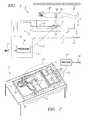
- FIG. 1illustrates an embodiment of a focused ultrasound system, including an ultrasound transducer, a system for positioning the transducer, and an MRI system, in accordance with the present invention.
- FIG. 2is a preferred embodiment of a system for positioning the transducer of the system shown in FIG. 1 .
- FIG. 3is a perspective view of an exemplary embodiment of an ultrasonic transducer including a sensor for use with the system of FIGS. 1 and 2 .
- FIG. 4is a perspective view of the transducer of FIG. 3 , showing exemplary coordinate systems.
- FIG. 5is a flow chart illustrating a method for calibrating a tilt sensor carried by an ultrasonic transducer, in accordance with the present invention.
- FIG. 1illustrates an exemplary embodiment of a focused ultrasound system 8 including an ultrasonic transducer 14 , a positioning system 10 for positioning the transducer 14 , and a magnetic resonance imaging (“MRI”) system 22 .
- the positioning system 10includes a positioner 12 coupled to the transducer 14 , a sensor 16 carried by the transducer 14 , and a processor 18 coupled to the positioner 12 and sensor 16 , as explained further below.
- the transducer 14may be mounted within a chamber 27 filled with degassed water or similar acoustically transmitting fluid.
- the chamber 27may be located within a table 34 upon which a patient 20 may be disposed, or within a fluid-filled bag mounted on a movable arm that may be placed against a patient's body (not shown).
- the contact surface of the chamber 27e.g., the top 24 of the table 34 , generally includes a flexible membrane (not shown) that is substantially transparent to ultrasound, such as mylar, polyvinyl chloride (PVC), or other suitable plastic material.
- PVCpolyvinyl chloride
- a fluid-filled bag(not shown) may be provided on the membrane that may conform easily to the contours of the patient 20 disposed on the table, thereby acoustically coupling the patient 20 to the transducer 14 within the chamber 27 .
- acoustic gel, water, or other fluidmay be provided between the patient 20 and the membrane to facilitate further acoustic coupling between the transducer 14 and the patient 20 .
- the transducer 14may be used in conjunction with an imaging system.
- the table 34may be positioned within an imaging volume 21 of an MRI system 22 , such as that disclosed in U.S. Pat. Nos. 5,247,935, 5,291,890, 5,368,031, 5,368,032, 5,443,068 issued to Cline et al., and U.S. Pat. Nos. 5,307,812, 5,323,779, 5,327,884 issued to Hardy et al., the disclosures of which are expressly incorporated herein by reference.
- the positioner 12may move the transducer 14 in one or more degrees of freedom. For example, the transducer 14 may be rotated, or translated relative to the patient 20 .
- the positioner 12is typically distanced away from the MRI system 22 , e.g., outside the imaging volume 21 in order to minimize interference.
- Known positionerswhich may include one or more motors, drive shafts, joints, and the like, have been described in U.S. Pat. Nos. 5,443,068, 5,275,165, and 5,247,935, and in the U.S. patent application Ser. No. 09/628,964, the disclosures of which are expressly incorporated by reference herein.
- FIG. 2illustrates a system 10 for positioning the transducer 14 according to a preferred embodiment.
- positioningincludes translating or moving the transducer 14 to a new location in space, as well as rotating or tilting the transducer 14 about an axis to achieve a new orientation of the transducer 14 .
- the positioner 12 shown in FIG. 2may provide roll and pitch control of the transducer 14 , as well as lateral and longitudinal control, as explained further below.
- the positioner 12may include piezoelectric vibrational motors 86 that may operate within the field of an MRI system without interfering substantially with its operation, such as those described in U.S. patent application Ser. No. 09/628,964, filed Jul. 31, 2000, which is incorporated by reference herein.
- the motors 86may provide a braking force to the drive shafts (not shown) while de-energized and thus aid in preventing motor slippage or backlash.
- the positioner 12may also include a set of encoders (not shown), which are described in the U.S. patent application Ser. No. 09/628,964, coupled to the positioning motors 86 to control the position of the transducer 14 .”
- the transducer 14may include a single piezoelectric transducer element, or may include multiple piezoelectric elements (not shown) together providing a transducer array.
- the transducer 14may have a concave or bowl shape, such as a “spherical cap” shape, i.e., having a substantially constant radius of curvature such that the transducer 14 has an inside surface defining a portion of a sphere.
- the transducer 14may have a substantially flat configuration (not shown), and/or may include an outer perimeter that is generally, but not necessarily, circular.
- the transducer 14may be divided into any desired number of rings and/or sectors (not shown).
- the transducer 14may have an outer diameter of between about eight and twelve centimeters (8–12 cm), a radius of curvature between about eight and sixteen centimeters (8–16 cm), and may include between ten and thirty (10–30) rings and between four and sixteen (4–16) sectors.
- the transducer 14may include one or more transducer elements having a variety of geometric shapes, such as hexagons, triangles, squares, and the like, and may be disposed about a central axis, preferably but not necessarily, in a substantially uniform or symmetrical configuration.
- the configuration of the transducer 14is not important to the present invention, and any of a variety of transducers may be used, such as flat circular arrays, linear arrays, and the like. Additional information on the construction of transducers appropriate for use with the present invention may be found, for example, in co-pending application Ser. No. 09/884,206, filed Jun. 9, 2001. The disclosure of this application and any references cited therein are expressly incorporated herein by reference.
- the transducer 14may be movable within the chamber 27 (not shown, see FIG. 1 ), e.g., translated along a first or longitudinal axis 52 , and/or along a second or transverse axis 54 .
- the axes 52 , 54may define orthogonal coordinates (such as “X” and “Y” as shown in FIG. 4 , and discussed further below) forming a plane that is substantially parallel to the top 24 of the table 34 (not shown, see FIG. 1 ).
- the transducer 14may also be rotatable about the axis 52 , as illustrated by arrow 56 , showing a “pitch” motion, and/or about the axis 54 , as illustrated by arrow 58 , showing a “roll” motion.
- the focal zone 26 of the transducer 14may also be adjustable along a Z-axis 60 (an axis substantially normal to the surface of the transducer 14 or a plane defined by axes 52 , 54 ) electronically, as is know to those skilled in the art.
- the positioner 12may also mechanically move the transducer 14 along an axis (not shown) that may be normal to a plane defined by axes 52 , 54 .
- the transducer 14may be supported by a holder or frame 62 including one or more pivotal supports 64 , which may allow the transducer 14 to rotate about one of the axes 52 , 54 (axis 52 shown) relative to the holder 62 .
- the transducer holder 62may be rotatably supported at support 66 , allowing the transducer 14 to rotate about the other one of the axes 52 , 54 (axis 54 shown).
- the support 66may be pivotally connected to other components of the positioner 12 , such as the translational mechanisms 13 shown in FIGS. 1 and 2 .
- the translational mechanisms 13may be movable within the chamber 27 , e.g., along the axes 52 , 54 for translating the transducer 14 within the plane defined by the axes 52 , 54 .
- the holder 62 and the supports 64 and 66may be part of the positioner 12 such that the positioner 12 may rotate the transducer 14 about the supports 64 and 66 , and thereby, about the pitch and roll axes, 52 and 54 , respectively.
- other frame or support structuresmay be provided for supporting the transducer 14 , as will be appreciated by those skilled in the art, and the present invention is not limited to the exemplary embodiment shown in FIGS. 2 and 3 .
- the senor 16is mounted internally within a portion of the transducer 14 as shown in FIG. 3 . This may eliminate the need to make the sensor water proof, and may allow spare wires already provided in transducer cables (not shown) to be used to couple the sensor 16 , e.g., to the processor 18 (not shown).
- the sensor 16may also be mounted to an external surface (not shown) of the ultrasonic transducer 14 .
- the sensor 16may be provided in substantially sealed packaging, e.g., within a waterproof casing to prevent fluid surrounding the transducer 14 from damaging the sensor 16 .
- the senor 16is substantially fixed to the transducer 14 such that a rotational orientation of the sensor 16 may be correlated to a rotational orientation of the transducer 14 , as explained further below.
- the sensor 16is configured to measure a location or an orientation of the transducer 14 with respect to a known coordinate system, such as a coordinate system of the MRI volume.
- the sensor 16may be a location sensor that measures a relative location between the transducer 14 and at least one known reference point. Location sensors, such as those that use infrared technology, are well known in the art.
- the position sensor 16may be a tilt sensor that measures tilt angles with respect to a roll axis and/or a pitch axis of the transducer 14 .
- Sensor 16preferably measures tilt angle by sensing gravity field acceleration.
- a 2-axis solid-state miniature accelerometeravailable from Analog Devices Inc., Norwood, Mass., U.S., (Part Number ADXL202EB-232A), may be used for measuring tilt angles by sensing the gravity field acceleration components due to a tilt of the transducer 14 .
- the accelerometer chipmay be made MR compliant by providing it within a case made of MR compliant materials.
- the components of the sensor 16 , as well as the supporting hardware of the sensor 16are preferably made of materials that are MR-compliant in order to reduce image artifacts.
- Materials that are MR-compliantinclude non-magnetic materials such as plastic, copper, brass, alumina, ceramic, or glass.
- the processor 18may include one or more logic circuits, a microprocessor, and/or computers coupled to the sensor 16 to receive signals from the sensor 16 , and to the positioner 12 for directing the positioner 12 to move the transducer 14 in a translational or rotational motion.
- the processor 18may be a separate subsystem from a controller or other subsystems (not shown) used to operate the transducer 14 and/or the MRI system 22 .
- the processor 18may be included in a computer that includes hardware components and/or software modules for performing other functions of the system 8 , e.g., controlling the transducer 14 and/or the MRI system 22 .
- a first communication path 28 allowing signals to be communicated from the sensor 16 to the processor 18may include one or more wires coupling the sensor 16 to the processor 18 .
- the first communication path 28may include an optical cable and/or a wireless transmitter for transmitting signals from the sensor 16 to the processor 18 .
- a wireless transmittermay transmit signals, such as radio frequency, infrared, or other signals, to a receiver (not shown) coupled to the processor 18 . The frequency of such radio frequency signals may be selected to minimize interference with the MRI system.
- the second communication path 30which couples the processor 18 and the positioner 12 , may include one or more wires, optical cables, and/or a wireless transmitter.
- the positioning system 10may also include an interface, such as a keyboard, a mouse, and/or touch screen (not shown) for providing an input 32 to the processor 18 , the positioner 12 , and/or other components of the system 8 , as described below.
- an interfacesuch as a keyboard, a mouse, and/or touch screen (not shown) for providing an input 32 to the processor 18 , the positioner 12 , and/or other components of the system 8 , as described below.
- a usermay enter an input 32 , preferably through the interface, which may define or otherwise include a desired position of the transducer 14 .
- positionmay include one or both of a location in space (e.g., in one, two, or three dimensions) and an orientation (e.g., a pitch or roll angle) of the transducer 14 .
- the desired position of the transducer 14includes a translation location along the axes 52 and/or 54 and/or a rotational orientation of the transducer 14 about axes 52 and/or 54 .
- the processor 18may transmit a signal to the positioner, instructing the positioner 12 to move the transducer 14 based at least in part on the input 32 to the desired position. For example, the processor 18 may instruct the positioner 12 to move the transducer 14 based upon a calculation performed by the processor 18 , e.g., a difference between the desired position and a current position of the transducer 14 .
- the positioner 12may receive the input 32 directly and may move the transducer 14 based at least in part on the input 32 .
- the input 32(or the desired position) may be transmitted from the positioner 12 to the processor 18 .
- the sensor 16may measure an actual position of the transducer 14 and compare it to the desired position.
- the processor 18may receive one or more data signals from the sensor 16 , e.g., via the first communication path 28 .
- the processor 18may then determine the true tilt angle based on the sensor measurement and, optionally, a set of calibration coefficients.
- the calibration coefficientsmay be associated with coordinate transformation, as is known in the art, which relates the mounting position of the sensor 16 to the coordinate system of the transducer 14 .
- the calibration coefficientsmay be used to correct misalignment between the coordinate systems of the transducer 14 and the sensor 16 , and to account for the geometric relation between the sensor's measurement axis and the transducer rotation axis, as discussed previously.
- the calibration coefficientsmay be initially or periodically determined using a calibration procedure, such as that discussed below.
- the processor 18may direct the positioner 12 to adjust the position of the transducer 14 , for example, based on the difference between the true position and the desired position.
- This iterative process of obtaining the position data, determining the true position, comparing the true and desired positions, and adjusting the position of the ultrasonic transducer 14may be repeated until the desired position associated with the user's input 32 is achieved within an acceptable tolerance level.
- the desired tilt anglemay be considered to be achieved if the true tilt angle is within a predetermined range around the desired tilt angle, such as within 0.25 degree of the desired tilt angle.
- FIG. 4movement of the transducer 14 of FIGS. 2 and 3 is shown relative to a fixed coordinate system.
- the roll axis 52 , the pitch axis 54 , and the vertical axis 60define X, Y, and Z axes, respectively.
- the sensor 16(shown in phantom), is preferably fixed to the transducer 14 , and includes its own coordinate system, represented as X′, Y′, and Z′.
- the coordinate system of the sensor 16may substantially overlap the X-Y-Z coordinate system.
- internal transducer components, as well as mounting inaccuracymay prevent precise alignment of the sensor 16 with the roll axis 106 and the pitch axis 108 .
- alignment deviationsuch as ⁇ X or ⁇ Y
- sensor 16may be mounted with its axis, X′, Y′, and Z′ defining angles ⁇ X , ⁇ Y , and ⁇ Z , respectively, with the corresponding axis, X, Y, and Z, of the transducer 14 . Therefore, before operating the system, the sensor 16 may be calibrated to account for the geometric relation between the sensor's measurement axis, X′, Y′, and Z′, and the transducer axis, X, Y, and Z. Furthermore, since sensors that measure tilt angles may measure tilt angles with respect to gravity vectors, rather than with respect to the transducer axis, calibration may be needed to account for this as well.
- FIG. 5is a flowchart illustrating a method 200 for calibrating a tilt sensor 16 mounted to a transducer 14 (not shown, see FIGS. 3 and 4 ), such as that described above.
- the transducer 14may be tilted about an axis, such as a roll axis or a pitch axis, to a plurality of angles within a range of prescribed angles.
- the transducer 14may be tilted over a range that exceeds a range of angles likely to be used during an actual operation of the transducer 14 . This may ensure that a complete operational range of angles is calibrated.
- range of prescribed anglesmay range from ⁇ 30° to +30° with respect to the vertical axis of the transducer 14 .
- step 204a sensor signal is obtained with the transducer 14 positioned at each of the prescribed angles. Then, in step 206 , coefficients associated with coordinate transformation may be computed, that best match the sensor measurements with the corresponding prescribed angles. The coefficients may account for any imperfect mounting of the sensor, as discussed previously.
- step 208the transducer 14 is again tilted about the same axis within a range of prescribed angles.
- the range of the prescribed angles in step 208may be the same as or preferably different from the range of prescribed angles in step 202 . Again, as discussed previously, the transducer 14 may be tilted within a range that exceeds the range of angles used during actual operation of the transducer 14 .
- step 210sensor measurements are obtained at each of the prescribed angles generated in step 208 . The sensor measurements are then calibrated using the coefficients obtained in step 206 to determine the actual tilt angle of the transducer 14 at each of the prescribed angles.
- each of the actual tilt anglesmay be compared with each of the prescribed angles generated in step 208 . If the difference is within an acceptable range, preferably within 0.3 degree, then the calibration procedure is finished.
- the sensormay be re-calibrated. Preferably, there should be a prescribed number of times for repeating calibration of the sensor 16 .
- step 216it is determined whether the prescribed number of times is met. If the sensor has only been calibrated once, for example, then the calibration procedure may be repeated starting at step 202 , as shown by the arrow 214 defining a process loop. After a prescribed number of calibrations, if the sensor measurements cannot be calibrated to match the prescribed angles within an acceptable range of error, the sensor 16 may be replaced, as shown in step 218 .
- the calibration procedure described abovemay be performed for each axis.
- the coefficientsmay account for sensor readings in all axes.
- the calibration procedure described aboveneeds to be performed for each of the sensors. It should be noted that although a calibration method for a tilt sensor is described above, the same concept also applies to a calibration method for a position sensor that measures a location of the ultrasonic transducer.
- the embodiments abovehave been described in reference to ultrasonic transducer used in conjunction with a MRI system, the scope of the invention is not so limited.
- the present inventionalso applies to other imaging modalities such as computed tomagraphy and other medical devices that require precise positioning.
- laser devicesthat are machine-coordinated or medical devices for cutting biological tissue, such as oscillation knives, may use the system described herein to ensure that the devices are positioned and aimed correctly at the target tissue. This ensures proper treatment and prevents injury to the patient.
Landscapes
- Health & Medical Sciences (AREA)
- Life Sciences & Earth Sciences (AREA)
- Surgery (AREA)
- Public Health (AREA)
- Veterinary Medicine (AREA)
- Nuclear Medicine, Radiotherapy & Molecular Imaging (AREA)
- General Health & Medical Sciences (AREA)
- Engineering & Computer Science (AREA)
- Biomedical Technology (AREA)
- Heart & Thoracic Surgery (AREA)
- Medical Informatics (AREA)
- Molecular Biology (AREA)
- Animal Behavior & Ethology (AREA)
- Biophysics (AREA)
- Radiology & Medical Imaging (AREA)
- Physics & Mathematics (AREA)
- Pathology (AREA)
- Orthopedic Medicine & Surgery (AREA)
- Vascular Medicine (AREA)
- Ultra Sonic Daignosis Equipment (AREA)
- Magnetic Resonance Imaging Apparatus (AREA)
Abstract
Description
Claims (26)
Priority Applications (2)
| Application Number | Priority Date | Filing Date | Title |
|---|---|---|---|
| US10/106,562US7128711B2 (en) | 2002-03-25 | 2002-03-25 | Positioning systems and methods for guided ultrasound therapy systems |
| EP03075831AEP1348385A1 (en) | 2002-03-25 | 2003-03-21 | Positioning systems for guided ultrasound therapy systems |
Applications Claiming Priority (1)
| Application Number | Priority Date | Filing Date | Title |
|---|---|---|---|
| US10/106,562US7128711B2 (en) | 2002-03-25 | 2002-03-25 | Positioning systems and methods for guided ultrasound therapy systems |
Publications (2)
| Publication Number | Publication Date |
|---|---|
| US20030181806A1 US20030181806A1 (en) | 2003-09-25 |
| US7128711B2true US7128711B2 (en) | 2006-10-31 |
Family
ID=27804350
Family Applications (1)
| Application Number | Title | Priority Date | Filing Date |
|---|---|---|---|
| US10/106,562Expired - LifetimeUS7128711B2 (en) | 2002-03-25 | 2002-03-25 | Positioning systems and methods for guided ultrasound therapy systems |
Country Status (2)
| Country | Link |
|---|---|
| US (1) | US7128711B2 (en) |
| EP (1) | EP1348385A1 (en) |
Cited By (75)
| Publication number | Priority date | Publication date | Assignee | Title |
|---|---|---|---|---|
| US20050054954A1 (en)* | 2002-01-15 | 2005-03-10 | Lars Lidgren | Device for mini-invasive ultrasound treatment of an object by a heat-isolated transducer |
| US20080033292A1 (en)* | 2006-08-02 | 2008-02-07 | Insightec Ltd | Ultrasound patient interface device |
| US20090036802A1 (en)* | 2005-12-27 | 2009-02-05 | Long Wang | Swing Type High-Intensity Focused Ultrasound Therapeutic Apparatus and Mri Guided High-Intensity Focused Ultrasound Therapeutic System Having Such a Swing Type Apparatus |
| US20090093708A1 (en)* | 2005-07-29 | 2009-04-09 | Long Wang | MRI guided high-intensity focused ultrasonic therapeutic system |
| US20090240146A1 (en)* | 2007-10-26 | 2009-09-24 | Liposonix, Inc. | Mechanical arm |
| US20100010595A1 (en)* | 2006-08-30 | 2010-01-14 | Koninklijke Philips Electronics N. V. | Apparatus for thermal treatment of tissue |
| US20100103432A1 (en)* | 2008-10-27 | 2010-04-29 | Mcginnis William J | Positioning system and method of using same |
| US20100125192A1 (en)* | 2008-11-17 | 2010-05-20 | Rajiv Chopra | Focused ultrasound system |
| US20100174188A1 (en)* | 2006-08-24 | 2010-07-08 | Chongqing Ronghai Medical Ultrasound Industry Ltd. | High Intensity Focused Ultrasound Therapeutic System Guided by an Imaging Device |
| US20110087103A1 (en)* | 2009-10-14 | 2011-04-14 | Patrick Gross | Ultrasound focus positioning device |
| US20110118695A1 (en)* | 2009-11-13 | 2011-05-19 | Searete Llc, A Limited Liability Corporation Of The State Of Delaware | Device, system, and method for targeted delivery of anti-inflammatory medicaments to a mammalian subject |
| US20110118560A1 (en)* | 2009-11-13 | 2011-05-19 | Searete Llc, A Limited Liability Corporation Of The State Of Delaware | Device, system, and method for targeted delivery of anti-inflammatory medicaments to a mammalian subject |
| US20110118698A1 (en)* | 2009-11-13 | 2011-05-19 | Searete Llc, A Limited Liability Corporation Of The State Of Delaware | Device, system, and method for targeted delivery of anti-inflammatory medicaments to a mammalian subject |
| US8002706B2 (en) | 2003-05-22 | 2011-08-23 | Insightec Ltd. | Acoustic beam forming in phased arrays including large numbers of transducer elements |
| US8057408B2 (en) | 2005-09-22 | 2011-11-15 | The Regents Of The University Of Michigan | Pulsed cavitational ultrasound therapy |
| US8088067B2 (en) | 2002-12-23 | 2012-01-03 | Insightec Ltd. | Tissue aberration corrections in ultrasound therapy |
| US8137274B2 (en) | 1999-10-25 | 2012-03-20 | Kona Medical, Inc. | Methods to deliver high intensity focused ultrasound to target regions proximate blood vessels |
| US8167805B2 (en) | 2005-10-20 | 2012-05-01 | Kona Medical, Inc. | Systems and methods for ultrasound applicator station keeping |
| US8235901B2 (en) | 2006-04-26 | 2012-08-07 | Insightec, Ltd. | Focused ultrasound system with far field tail suppression |
| US8251908B2 (en) | 2007-10-01 | 2012-08-28 | Insightec Ltd. | Motion compensated image-guided focused ultrasound therapy system |
| US8295912B2 (en) | 2009-10-12 | 2012-10-23 | Kona Medical, Inc. | Method and system to inhibit a function of a nerve traveling with an artery |
| USRE43901E1 (en) | 2000-11-28 | 2013-01-01 | Insightec Ltd. | Apparatus for controlling thermal dosing in a thermal treatment system |
| US8368401B2 (en) | 2009-11-10 | 2013-02-05 | Insightec Ltd. | Techniques for correcting measurement artifacts in magnetic resonance thermometry |
| US8374674B2 (en) | 2009-10-12 | 2013-02-12 | Kona Medical, Inc. | Nerve treatment system |
| US8409099B2 (en) | 2004-08-26 | 2013-04-02 | Insightec Ltd. | Focused ultrasound system for surrounding a body tissue mass and treatment method |
| US8425424B2 (en) | 2008-11-19 | 2013-04-23 | Inightee Ltd. | Closed-loop clot lysis |
| US8469904B2 (en) | 2009-10-12 | 2013-06-25 | Kona Medical, Inc. | Energetic modulation of nerves |
| US8512262B2 (en) | 2009-10-12 | 2013-08-20 | Kona Medical, Inc. | Energetic modulation of nerves |
| US8517962B2 (en) | 2009-10-12 | 2013-08-27 | Kona Medical, Inc. | Energetic modulation of nerves |
| US8539813B2 (en) | 2009-09-22 | 2013-09-24 | The Regents Of The University Of Michigan | Gel phantoms for testing cavitational ultrasound (histotripsy) transducers |
| US8608672B2 (en) | 2005-11-23 | 2013-12-17 | Insightec Ltd. | Hierarchical switching in ultra-high density ultrasound array |
| US8617073B2 (en) | 2009-04-17 | 2013-12-31 | Insightec Ltd. | Focusing ultrasound into the brain through the skull by utilizing both longitudinal and shear waves |
| US8622937B2 (en) | 1999-11-26 | 2014-01-07 | Kona Medical, Inc. | Controlled high efficiency lesion formation using high intensity ultrasound |
| US8661873B2 (en) | 2009-10-14 | 2014-03-04 | Insightec Ltd. | Mapping ultrasound transducers |
| US8852103B2 (en) | 2011-10-17 | 2014-10-07 | Butterfly Network, Inc. | Transmissive imaging and related apparatus and methods |
| US8932237B2 (en) | 2010-04-28 | 2015-01-13 | Insightec, Ltd. | Efficient ultrasound focusing |
| US8979871B2 (en) | 2009-08-13 | 2015-03-17 | Monteris Medical Corporation | Image-guided therapy of a tissue |
| US8986211B2 (en) | 2009-10-12 | 2015-03-24 | Kona Medical, Inc. | Energetic modulation of nerves |
| US8986231B2 (en) | 2009-10-12 | 2015-03-24 | Kona Medical, Inc. | Energetic modulation of nerves |
| US8992447B2 (en) | 2009-10-12 | 2015-03-31 | Kona Medical, Inc. | Energetic modulation of nerves |
| US9005143B2 (en) | 2009-10-12 | 2015-04-14 | Kona Medical, Inc. | External autonomic modulation |
| US9049783B2 (en) | 2012-04-13 | 2015-06-02 | Histosonics, Inc. | Systems and methods for obtaining large creepage isolation on printed circuit boards |
| US9061131B2 (en) | 2009-08-17 | 2015-06-23 | Histosonics, Inc. | Disposable acoustic coupling medium container |
| US9144694B2 (en) | 2011-08-10 | 2015-09-29 | The Regents Of The University Of Michigan | Lesion generation through bone using histotripsy therapy without aberration correction |
| US9177543B2 (en) | 2009-08-26 | 2015-11-03 | Insightec Ltd. | Asymmetric ultrasound phased-array transducer for dynamic beam steering to ablate tissues in MRI |
| US9289154B2 (en) | 2009-08-19 | 2016-03-22 | Insightec Ltd. | Techniques for temperature measurement and corrections in long-term magnetic resonance thermometry |
| US9333038B2 (en) | 2000-06-15 | 2016-05-10 | Monteris Medical Corporation | Hyperthermia treatment and probe therefore |
| US9433383B2 (en) | 2014-03-18 | 2016-09-06 | Monteris Medical Corporation | Image-guided therapy of a tissue |
| US9504484B2 (en) | 2014-03-18 | 2016-11-29 | Monteris Medical Corporation | Image-guided therapy of a tissue |
| US9623266B2 (en) | 2009-08-04 | 2017-04-18 | Insightec Ltd. | Estimation of alignment parameters in magnetic-resonance-guided ultrasound focusing |
| US9636133B2 (en) | 2012-04-30 | 2017-05-02 | The Regents Of The University Of Michigan | Method of manufacturing an ultrasound system |
| US9667889B2 (en) | 2013-04-03 | 2017-05-30 | Butterfly Network, Inc. | Portable electronic devices with integrated imaging capabilities |
| US9852727B2 (en) | 2010-04-28 | 2017-12-26 | Insightec, Ltd. | Multi-segment ultrasound transducers |
| US9901753B2 (en) | 2009-08-26 | 2018-02-27 | The Regents Of The University Of Michigan | Ultrasound lithotripsy and histotripsy for using controlled bubble cloud cavitation in fractionating urinary stones |
| US9943708B2 (en) | 2009-08-26 | 2018-04-17 | Histosonics, Inc. | Automated control of micromanipulator arm for histotripsy prostate therapy while imaging via ultrasound transducers in real time |
| US9981148B2 (en) | 2010-10-22 | 2018-05-29 | Insightec, Ltd. | Adaptive active cooling during focused ultrasound treatment |
| US10039689B1 (en) | 2012-12-16 | 2018-08-07 | Zoya Hajianpour | Hand and foot massager |
| US10130828B2 (en) | 2005-06-21 | 2018-11-20 | Insightec Ltd. | Controlled, non-linear focused ultrasound treatment |
| US10219815B2 (en) | 2005-09-22 | 2019-03-05 | The Regents Of The University Of Michigan | Histotripsy for thrombolysis |
| US10293187B2 (en) | 2013-07-03 | 2019-05-21 | Histosonics, Inc. | Histotripsy excitation sequences optimized for bubble cloud formation using shock scattering |
| US10327830B2 (en) | 2015-04-01 | 2019-06-25 | Monteris Medical Corporation | Cryotherapy, thermal therapy, temperature modulation therapy, and probe apparatus therefor |
| US10675113B2 (en) | 2014-03-18 | 2020-06-09 | Monteris Medical Corporation | Automated therapy of a three-dimensional tissue region |
| US10772681B2 (en) | 2009-10-12 | 2020-09-15 | Utsuka Medical Devices Co., Ltd. | Energy delivery to intraparenchymal regions of the kidney |
| US10780298B2 (en) | 2013-08-22 | 2020-09-22 | The Regents Of The University Of Michigan | Histotripsy using very short monopolar ultrasound pulses |
| US10925579B2 (en) | 2014-11-05 | 2021-02-23 | Otsuka Medical Devices Co., Ltd. | Systems and methods for real-time tracking of a target tissue using imaging before and during therapy delivery |
| US11058399B2 (en) | 2012-10-05 | 2021-07-13 | The Regents Of The University Of Michigan | Bubble-induced color doppler feedback during histotripsy |
| US11135454B2 (en) | 2015-06-24 | 2021-10-05 | The Regents Of The University Of Michigan | Histotripsy therapy systems and methods for the treatment of brain tissue |
| US11432900B2 (en) | 2013-07-03 | 2022-09-06 | Histosonics, Inc. | Articulating arm limiter for cavitational ultrasound therapy system |
| US11564656B2 (en) | 2018-03-13 | 2023-01-31 | Verathon Inc. | Generalized interlaced scanning with an ultrasound probe |
| US11648424B2 (en) | 2018-11-28 | 2023-05-16 | Histosonics Inc. | Histotripsy systems and methods |
| US11813485B2 (en) | 2020-01-28 | 2023-11-14 | The Regents Of The University Of Michigan | Systems and methods for histotripsy immunosensitization |
| US11998266B2 (en) | 2009-10-12 | 2024-06-04 | Otsuka Medical Devices Co., Ltd | Intravascular energy delivery |
| US12318636B2 (en) | 2022-10-28 | 2025-06-03 | Histosonics, Inc. | Histotripsy systems and methods |
| US12343568B2 (en) | 2020-08-27 | 2025-07-01 | The Regents Of The University Of Michigan | Ultrasound transducer with transmit-receive capability for histotripsy |
| US12402802B2 (en) | 2011-08-31 | 2025-09-02 | Insightec Ltd. | Avoiding MRI-interference with co-existing systems |
Families Citing this family (26)
| Publication number | Priority date | Publication date | Assignee | Title |
|---|---|---|---|---|
| US8221322B2 (en) | 2002-06-07 | 2012-07-17 | Verathon Inc. | Systems and methods to improve clarity in ultrasound images |
| US8221321B2 (en) | 2002-06-07 | 2012-07-17 | Verathon Inc. | Systems and methods for quantification and classification of fluids in human cavities in ultrasound images |
| GB2391625A (en) | 2002-08-09 | 2004-02-11 | Diagnostic Ultrasound Europ B | Instantaneous ultrasonic echo measurement of bladder urine volume with a limited number of ultrasound beams |
| US7819806B2 (en) | 2002-06-07 | 2010-10-26 | Verathon Inc. | System and method to identify and measure organ wall boundaries |
| US20070276247A1 (en)* | 2002-06-07 | 2007-11-29 | Vikram Chalana | Systems and methods for ultrasound imaging using an inertial reference unit |
| FR2869547B1 (en)* | 2004-04-29 | 2007-03-30 | Centre Nat Rech Scient Cnrse | DEVICE FOR POSITIONING ENERGY GENERATING MEANS OF AN ASSEMBLY FOR THE THERMAL TREATMENT OF BIOLOGICAL TISSUES |
| EP1866871A4 (en)* | 2005-03-30 | 2012-01-04 | Worcester Polytech Inst | ULTRASONIC DIAGNOSTIC IMAGING IN THREE-DIMENSIONS HANDLING WITH POSITION AND ANGLE DETERMINATION SENSORS |
| CN101484084B (en)* | 2006-04-11 | 2012-08-29 | 皇家飞利浦电子股份有限公司 | Device for positioning an ultrasound transducer inside an MR scanner |
| US8167803B2 (en) | 2007-05-16 | 2012-05-01 | Verathon Inc. | System and method for bladder detection using harmonic imaging |
| US8934961B2 (en) | 2007-05-18 | 2015-01-13 | Biomet Manufacturing, Llc | Trackable diagnostic scope apparatus and methods of use |
| US10226234B2 (en) | 2011-12-01 | 2019-03-12 | Maui Imaging, Inc. | Motion detection using ping-based and multiple aperture doppler ultrasound |
| US8655430B2 (en)* | 2007-12-26 | 2014-02-18 | National Health Research Institutes | Positioning system for thermal therapy |
| CA2732997C (en) | 2008-08-07 | 2017-03-14 | Verathon Inc. | Device, system, and method to measure abdominal aortic aneurysm diameter |
| US8914245B2 (en) | 2009-03-20 | 2014-12-16 | Andrew David Hopkins | Ultrasound probe with accelerometer |
| JP5702788B2 (en) | 2009-09-24 | 2015-04-15 | コーニンクレッカ フィリップス エヌ ヴェ | Positioning mechanism of high intensity focused ultrasound |
| JP6274724B2 (en) | 2010-02-18 | 2018-02-07 | マウイ イマギング,インコーポレーテッド | Point source transmission and sound velocity correction using multi-aperture ultrasound imaging |
| KR101906838B1 (en) | 2010-10-13 | 2018-10-11 | 마우이 이미징, 인코포레이티드 | Concave ultrasound transducers and 3d arrays |
| JP6438769B2 (en) | 2012-02-21 | 2018-12-19 | マウイ イマギング,インコーポレーテッド | Determination of material hardness using multiple aperture ultrasound. |
| WO2013148673A1 (en) | 2012-03-26 | 2013-10-03 | Maui Imaging, Inc. | Systems and methods for improving ultrasound image quality by applying weighting factors |
| JP6270843B2 (en)* | 2012-08-10 | 2018-01-31 | マウイ イマギング,インコーポレーテッド | Calibration of multiple aperture ultrasonic probes |
| US20140064513A1 (en) | 2012-09-06 | 2014-03-06 | MUSIC Group IP Ltd. | System and method for remotely controlling audio equipment |
| US9883848B2 (en) | 2013-09-13 | 2018-02-06 | Maui Imaging, Inc. | Ultrasound imaging using apparent point-source transmit transducer |
| CN106794007B (en) | 2014-08-18 | 2021-03-09 | 毛伊图像公司 | Network-based ultrasound imaging system |
| KR102681141B1 (en) | 2015-03-30 | 2024-07-02 | 마우이 이미징, 인코포레이티드 | Ultrasonic imaging systems and methods for detecting object motion |
| CN108778530B (en) | 2016-01-27 | 2021-07-27 | 毛伊图像公司 | Ultrasound imaging with sparse array detectors |
| WO2022188800A1 (en) | 2021-03-10 | 2022-09-15 | The University Of Hong Kong | A robotic platform to navigate mri-guided focused ultrasound system |
Citations (11)
| Publication number | Priority date | Publication date | Assignee | Title |
|---|---|---|---|---|
| US5443068A (en)* | 1994-09-26 | 1995-08-22 | General Electric Company | Mechanical positioner for magnetic resonance guided ultrasound therapy |
| US5526814A (en) | 1993-11-09 | 1996-06-18 | General Electric Company | Automatically positioned focussed energy system guided by medical imaging |
| US5553618A (en)* | 1993-03-12 | 1996-09-10 | Kabushiki Kaisha Toshiba | Method and apparatus for ultrasound medical treatment |
| DE19512956A1 (en) | 1995-04-10 | 1996-10-17 | Storz Medical Ag | Treatment and treatment unit using therapeutic pressure waves produced by source |
| US5583901A (en) | 1994-01-14 | 1996-12-10 | Siemens Aktiengesellschaft | Medical apparatus having an X-ray diagnostics installation |
| US5897495A (en)* | 1993-03-10 | 1999-04-27 | Kabushiki Kaisha Toshiba | Ultrasonic wave medical treatment apparatus suitable for use under guidance of magnetic resonance imaging |
| US5944663A (en)* | 1995-04-28 | 1999-08-31 | Siemens Aktiengesellschaft | Apparatus for treatment with acoustic waves |
| US6122538A (en)* | 1997-01-16 | 2000-09-19 | Acuson Corporation | Motion--Monitoring method and system for medical devices |
| DE10032982A1 (en) | 2000-07-10 | 2002-02-07 | Wolf Gmbh Richard | Positioning of therapy focus of therapy unit, such as lithotripter using X-ray unit with C-shaped support frame, so that X-ray target mark and therapy focus are automatically adjusted so that they coincide |
| US6546279B1 (en)* | 2001-10-12 | 2003-04-08 | University Of Florida | Computer controlled guidance of a biopsy needle |
| US6780153B2 (en)* | 2001-06-25 | 2004-08-24 | Angelsen Bjoern A. J. | Mechanism and system for 3-dimensional scanning of an ultrasound beam |
- 2002
- 2002-03-25USUS10/106,562patent/US7128711B2/ennot_activeExpired - Lifetime
- 2003
- 2003-03-21EPEP03075831Apatent/EP1348385A1/ennot_activeWithdrawn
Patent Citations (11)
| Publication number | Priority date | Publication date | Assignee | Title |
|---|---|---|---|---|
| US5897495A (en)* | 1993-03-10 | 1999-04-27 | Kabushiki Kaisha Toshiba | Ultrasonic wave medical treatment apparatus suitable for use under guidance of magnetic resonance imaging |
| US5553618A (en)* | 1993-03-12 | 1996-09-10 | Kabushiki Kaisha Toshiba | Method and apparatus for ultrasound medical treatment |
| US5526814A (en) | 1993-11-09 | 1996-06-18 | General Electric Company | Automatically positioned focussed energy system guided by medical imaging |
| US5583901A (en) | 1994-01-14 | 1996-12-10 | Siemens Aktiengesellschaft | Medical apparatus having an X-ray diagnostics installation |
| US5443068A (en)* | 1994-09-26 | 1995-08-22 | General Electric Company | Mechanical positioner for magnetic resonance guided ultrasound therapy |
| DE19512956A1 (en) | 1995-04-10 | 1996-10-17 | Storz Medical Ag | Treatment and treatment unit using therapeutic pressure waves produced by source |
| US5944663A (en)* | 1995-04-28 | 1999-08-31 | Siemens Aktiengesellschaft | Apparatus for treatment with acoustic waves |
| US6122538A (en)* | 1997-01-16 | 2000-09-19 | Acuson Corporation | Motion--Monitoring method and system for medical devices |
| DE10032982A1 (en) | 2000-07-10 | 2002-02-07 | Wolf Gmbh Richard | Positioning of therapy focus of therapy unit, such as lithotripter using X-ray unit with C-shaped support frame, so that X-ray target mark and therapy focus are automatically adjusted so that they coincide |
| US6780153B2 (en)* | 2001-06-25 | 2004-08-24 | Angelsen Bjoern A. J. | Mechanism and system for 3-dimensional scanning of an ultrasound beam |
| US6546279B1 (en)* | 2001-10-12 | 2003-04-08 | University Of Florida | Computer controlled guidance of a biopsy needle |
Cited By (143)
| Publication number | Priority date | Publication date | Assignee | Title |
|---|---|---|---|---|
| US8137274B2 (en) | 1999-10-25 | 2012-03-20 | Kona Medical, Inc. | Methods to deliver high intensity focused ultrasound to target regions proximate blood vessels |
| US8388535B2 (en) | 1999-10-25 | 2013-03-05 | Kona Medical, Inc. | Methods and apparatus for focused ultrasound application |
| US8277398B2 (en) | 1999-10-25 | 2012-10-02 | Kona Medical, Inc. | Methods and devices to target vascular targets with high intensity focused ultrasound |
| US8622937B2 (en) | 1999-11-26 | 2014-01-07 | Kona Medical, Inc. | Controlled high efficiency lesion formation using high intensity ultrasound |
| US9387042B2 (en) | 2000-06-15 | 2016-07-12 | Monteris Medical Corporation | Hyperthermia treatment and probe therefor |
| US9333038B2 (en) | 2000-06-15 | 2016-05-10 | Monteris Medical Corporation | Hyperthermia treatment and probe therefore |
| USRE43901E1 (en) | 2000-11-28 | 2013-01-01 | Insightec Ltd. | Apparatus for controlling thermal dosing in a thermal treatment system |
| US20050054954A1 (en)* | 2002-01-15 | 2005-03-10 | Lars Lidgren | Device for mini-invasive ultrasound treatment of an object by a heat-isolated transducer |
| US8088067B2 (en) | 2002-12-23 | 2012-01-03 | Insightec Ltd. | Tissue aberration corrections in ultrasound therapy |
| US8002706B2 (en) | 2003-05-22 | 2011-08-23 | Insightec Ltd. | Acoustic beam forming in phased arrays including large numbers of transducer elements |
| US8409099B2 (en) | 2004-08-26 | 2013-04-02 | Insightec Ltd. | Focused ultrasound system for surrounding a body tissue mass and treatment method |
| US10130828B2 (en) | 2005-06-21 | 2018-11-20 | Insightec Ltd. | Controlled, non-linear focused ultrasound treatment |
| US20090093708A1 (en)* | 2005-07-29 | 2009-04-09 | Long Wang | MRI guided high-intensity focused ultrasonic therapeutic system |
| US12303152B2 (en) | 2005-09-22 | 2025-05-20 | The Regents Of The University Of Michigan | Histotripsy for thrombolysis |
| US11701134B2 (en) | 2005-09-22 | 2023-07-18 | The Regents Of The University Of Michigan | Histotripsy for thrombolysis |
| US11364042B2 (en) | 2005-09-22 | 2022-06-21 | The Regents Of The University Of Michigan | Histotripsy for thrombolysis |
| US12150661B2 (en) | 2005-09-22 | 2024-11-26 | The Regents Of The University Of Michigan | Histotripsy for thrombolysis |
| US8057408B2 (en) | 2005-09-22 | 2011-11-15 | The Regents Of The University Of Michigan | Pulsed cavitational ultrasound therapy |
| US9642634B2 (en) | 2005-09-22 | 2017-05-09 | The Regents Of The University Of Michigan | Pulsed cavitational ultrasound therapy |
| US10219815B2 (en) | 2005-09-22 | 2019-03-05 | The Regents Of The University Of Michigan | Histotripsy for thrombolysis |
| US9220488B2 (en) | 2005-10-20 | 2015-12-29 | Kona Medical, Inc. | System and method for treating a therapeutic site |
| US8372009B2 (en) | 2005-10-20 | 2013-02-12 | Kona Medical, Inc. | System and method for treating a therapeutic site |
| US8167805B2 (en) | 2005-10-20 | 2012-05-01 | Kona Medical, Inc. | Systems and methods for ultrasound applicator station keeping |
| US8608672B2 (en) | 2005-11-23 | 2013-12-17 | Insightec Ltd. | Hierarchical switching in ultra-high density ultrasound array |
| US20090036802A1 (en)* | 2005-12-27 | 2009-02-05 | Long Wang | Swing Type High-Intensity Focused Ultrasound Therapeutic Apparatus and Mri Guided High-Intensity Focused Ultrasound Therapeutic System Having Such a Swing Type Apparatus |
| US8235901B2 (en) | 2006-04-26 | 2012-08-07 | Insightec, Ltd. | Focused ultrasound system with far field tail suppression |
| US20080033292A1 (en)* | 2006-08-02 | 2008-02-07 | Insightec Ltd | Ultrasound patient interface device |
| US20100174188A1 (en)* | 2006-08-24 | 2010-07-08 | Chongqing Ronghai Medical Ultrasound Industry Ltd. | High Intensity Focused Ultrasound Therapeutic System Guided by an Imaging Device |
| US20100010595A1 (en)* | 2006-08-30 | 2010-01-14 | Koninklijke Philips Electronics N. V. | Apparatus for thermal treatment of tissue |
| US8251908B2 (en) | 2007-10-01 | 2012-08-28 | Insightec Ltd. | Motion compensated image-guided focused ultrasound therapy system |
| US8548561B2 (en) | 2007-10-01 | 2013-10-01 | Insightec Ltd. | Motion compensated image-guided focused ultrasound therapy system |
| US20090240146A1 (en)* | 2007-10-26 | 2009-09-24 | Liposonix, Inc. | Mechanical arm |
| US20100103432A1 (en)* | 2008-10-27 | 2010-04-29 | Mcginnis William J | Positioning system and method of using same |
| US9101752B2 (en)* | 2008-11-17 | 2015-08-11 | Sunnybrook Health Sciences Centre | Computer controlled focused ultrasound positioning system for sequential beam emitting to sonicate discrete and interleaved tissue locations |
| US20100125192A1 (en)* | 2008-11-17 | 2010-05-20 | Rajiv Chopra | Focused ultrasound system |
| US8425424B2 (en) | 2008-11-19 | 2013-04-23 | Inightee Ltd. | Closed-loop clot lysis |
| US8617073B2 (en) | 2009-04-17 | 2013-12-31 | Insightec Ltd. | Focusing ultrasound into the brain through the skull by utilizing both longitudinal and shear waves |
| US9623266B2 (en) | 2009-08-04 | 2017-04-18 | Insightec Ltd. | Estimation of alignment parameters in magnetic-resonance-guided ultrasound focusing |
| US10610317B2 (en) | 2009-08-13 | 2020-04-07 | Monteris Medical Corporation | Image-guided therapy of a tissue |
| US9211157B2 (en) | 2009-08-13 | 2015-12-15 | Monteris Medical Corporation | Probe driver |
| US8979871B2 (en) | 2009-08-13 | 2015-03-17 | Monteris Medical Corporation | Image-guided therapy of a tissue |
| US9271794B2 (en) | 2009-08-13 | 2016-03-01 | Monteris Medical Corporation | Monitoring and noise masking of thermal therapy |
| US10188462B2 (en) | 2009-08-13 | 2019-01-29 | Monteris Medical Corporation | Image-guided therapy of a tissue |
| US9510909B2 (en) | 2009-08-13 | 2016-12-06 | Monteris Medical Corporation | Image-guide therapy of a tissue |
| US9061131B2 (en) | 2009-08-17 | 2015-06-23 | Histosonics, Inc. | Disposable acoustic coupling medium container |
| US9526923B2 (en) | 2009-08-17 | 2016-12-27 | Histosonics, Inc. | Disposable acoustic coupling medium container |
| US9289154B2 (en) | 2009-08-19 | 2016-03-22 | Insightec Ltd. | Techniques for temperature measurement and corrections in long-term magnetic resonance thermometry |
| US9177543B2 (en) | 2009-08-26 | 2015-11-03 | Insightec Ltd. | Asymmetric ultrasound phased-array transducer for dynamic beam steering to ablate tissues in MRI |
| US9943708B2 (en) | 2009-08-26 | 2018-04-17 | Histosonics, Inc. | Automated control of micromanipulator arm for histotripsy prostate therapy while imaging via ultrasound transducers in real time |
| US9901753B2 (en) | 2009-08-26 | 2018-02-27 | The Regents Of The University Of Michigan | Ultrasound lithotripsy and histotripsy for using controlled bubble cloud cavitation in fractionating urinary stones |
| US8539813B2 (en) | 2009-09-22 | 2013-09-24 | The Regents Of The University Of Michigan | Gel phantoms for testing cavitational ultrasound (histotripsy) transducers |
| US9174065B2 (en) | 2009-10-12 | 2015-11-03 | Kona Medical, Inc. | Energetic modulation of nerves |
| US8295912B2 (en) | 2009-10-12 | 2012-10-23 | Kona Medical, Inc. | Method and system to inhibit a function of a nerve traveling with an artery |
| US8986211B2 (en) | 2009-10-12 | 2015-03-24 | Kona Medical, Inc. | Energetic modulation of nerves |
| US8986231B2 (en) | 2009-10-12 | 2015-03-24 | Kona Medical, Inc. | Energetic modulation of nerves |
| US8992447B2 (en) | 2009-10-12 | 2015-03-31 | Kona Medical, Inc. | Energetic modulation of nerves |
| US9005143B2 (en) | 2009-10-12 | 2015-04-14 | Kona Medical, Inc. | External autonomic modulation |
| US9579518B2 (en) | 2009-10-12 | 2017-02-28 | Kona Medical, Inc. | Nerve treatment system |
| US9358401B2 (en) | 2009-10-12 | 2016-06-07 | Kona Medical, Inc. | Intravascular catheter to deliver unfocused energy to nerves surrounding a blood vessel |
| US11998266B2 (en) | 2009-10-12 | 2024-06-04 | Otsuka Medical Devices Co., Ltd | Intravascular energy delivery |
| US9352171B2 (en) | 2009-10-12 | 2016-05-31 | Kona Medical, Inc. | Nerve treatment system |
| US8374674B2 (en) | 2009-10-12 | 2013-02-12 | Kona Medical, Inc. | Nerve treatment system |
| US10772681B2 (en) | 2009-10-12 | 2020-09-15 | Utsuka Medical Devices Co., Ltd. | Energy delivery to intraparenchymal regions of the kidney |
| US8469904B2 (en) | 2009-10-12 | 2013-06-25 | Kona Medical, Inc. | Energetic modulation of nerves |
| US8715209B2 (en) | 2009-10-12 | 2014-05-06 | Kona Medical, Inc. | Methods and devices to modulate the autonomic nervous system with ultrasound |
| US9119952B2 (en) | 2009-10-12 | 2015-09-01 | Kona Medical, Inc. | Methods and devices to modulate the autonomic nervous system via the carotid body or carotid sinus |
| US9119951B2 (en) | 2009-10-12 | 2015-09-01 | Kona Medical, Inc. | Energetic modulation of nerves |
| US9125642B2 (en) | 2009-10-12 | 2015-09-08 | Kona Medical, Inc. | External autonomic modulation |
| US8512262B2 (en) | 2009-10-12 | 2013-08-20 | Kona Medical, Inc. | Energetic modulation of nerves |
| US9199097B2 (en) | 2009-10-12 | 2015-12-01 | Kona Medical, Inc. | Energetic modulation of nerves |
| US8556834B2 (en) | 2009-10-12 | 2013-10-15 | Kona Medical, Inc. | Flow directed heating of nervous structures |
| US8517962B2 (en) | 2009-10-12 | 2013-08-27 | Kona Medical, Inc. | Energetic modulation of nerves |
| US11154356B2 (en) | 2009-10-12 | 2021-10-26 | Otsuka Medical Devices Co., Ltd. | Intravascular energy delivery |
| US8661873B2 (en) | 2009-10-14 | 2014-03-04 | Insightec Ltd. | Mapping ultrasound transducers |
| US20110087103A1 (en)* | 2009-10-14 | 2011-04-14 | Patrick Gross | Ultrasound focus positioning device |
| US9412357B2 (en) | 2009-10-14 | 2016-08-09 | Insightec Ltd. | Mapping ultrasound transducers |
| US8368401B2 (en) | 2009-11-10 | 2013-02-05 | Insightec Ltd. | Techniques for correcting measurement artifacts in magnetic resonance thermometry |
| US9541621B2 (en) | 2009-11-10 | 2017-01-10 | Insightec, Ltd. | Techniques for correcting measurement artifacts in magnetic resonance thermometry |
| US20110118653A1 (en)* | 2009-11-13 | 2011-05-19 | Searete Llc, A Limited Liability Corporation Of The State Of Delaware | Device, system, and method for targeted delivery of anti-inflammatory medicaments to a mammalian subject |
| US8926584B2 (en) | 2009-11-13 | 2015-01-06 | The Invention Science Fund I, Llc | Device, system, and method for targeted delivery of anti-inflammatory medicaments to a mammalian subject |
| US8419707B2 (en) | 2009-11-13 | 2013-04-16 | The Invention Science Fund I, Llc | Device, system, and method for targeted delivery of anti-inflammatory medicaments to a mammalian subject |
| US9050303B2 (en) | 2009-11-13 | 2015-06-09 | The Invention Science Fund I, Llc | Device, system, and method for targeted delivery of anti-inflammatory medicaments to a mammalian subject |
| US8444622B2 (en) | 2009-11-13 | 2013-05-21 | The Invention Science Fund I, Llc | Device, system, and method for targeted delivery of anti-inflammatory medicaments to a mammalian subject |
| US8888761B2 (en) | 2009-11-13 | 2014-11-18 | The Invention Science Fund I, Llc | Device, system, and method for targeted delivery of anti-inflammatory medicaments to a mammalian subject |
| US8894630B2 (en) | 2009-11-13 | 2014-11-25 | The Invention Science Fund I, Llc | Device, system, and method for targeted delivery of anti-inflammatory medicaments to a mammalian subject |
| US20110118695A1 (en)* | 2009-11-13 | 2011-05-19 | Searete Llc, A Limited Liability Corporation Of The State Of Delaware | Device, system, and method for targeted delivery of anti-inflammatory medicaments to a mammalian subject |
| US20110118560A1 (en)* | 2009-11-13 | 2011-05-19 | Searete Llc, A Limited Liability Corporation Of The State Of Delaware | Device, system, and method for targeted delivery of anti-inflammatory medicaments to a mammalian subject |
| US20110117150A1 (en)* | 2009-11-13 | 2011-05-19 | Searete Llc. A Limited Liability Corporation Of The State Of Delaware | Device, system, and method for targeted delivery of anti-inflammatory medicaments to a mammalian subject |
| US20110118652A1 (en)* | 2009-11-13 | 2011-05-19 | Searete Llc, A Limited Liability Corporation Of The State Of Delaware | Device,system, and method for targeted delivery of anti-inflammatory medicaments to a mammalian subject |
| US20110118698A1 (en)* | 2009-11-13 | 2011-05-19 | Searete Llc, A Limited Liability Corporation Of The State Of Delaware | Device, system, and method for targeted delivery of anti-inflammatory medicaments to a mammalian subject |
| US8439896B2 (en) | 2009-11-13 | 2013-05-14 | The Invention Science Fund I, Llc | Device, system, and method for targeted delivery of anti-inflammatory medicaments to a mammalian subject |
| US9078863B2 (en) | 2009-11-13 | 2015-07-14 | The Invention Science Fund I, Llc | Device, system, and method for targeted delivery of anti-inflammatory medicaments to a mammalian subject |
| US20110118697A1 (en)* | 2009-11-13 | 2011-05-19 | Searete Llc, A Limited Liability Corporation Of The State Of Delaware | Device, system, and method for targeted delivery of anti-inflammatory medicaments to a mammalian subject |
| US9852727B2 (en) | 2010-04-28 | 2017-12-26 | Insightec, Ltd. | Multi-segment ultrasound transducers |
| US8932237B2 (en) | 2010-04-28 | 2015-01-13 | Insightec, Ltd. | Efficient ultrasound focusing |
| US9981148B2 (en) | 2010-10-22 | 2018-05-29 | Insightec, Ltd. | Adaptive active cooling during focused ultrasound treatment |
| US10071266B2 (en) | 2011-08-10 | 2018-09-11 | The Regents Of The University Of Michigan | Lesion generation through bone using histotripsy therapy without aberration correction |
| US9144694B2 (en) | 2011-08-10 | 2015-09-29 | The Regents Of The University Of Michigan | Lesion generation through bone using histotripsy therapy without aberration correction |
| US12402802B2 (en) | 2011-08-31 | 2025-09-02 | Insightec Ltd. | Avoiding MRI-interference with co-existing systems |
| US9149255B2 (en) | 2011-10-17 | 2015-10-06 | Butterfly Network, Inc. | Image-guided high intensity focused ultrasound and related apparatus and methods |
| US9268014B2 (en) | 2011-10-17 | 2016-02-23 | Butterfly Network, Inc. | Transmissive imaging and related apparatus and methods |
| US9247924B2 (en) | 2011-10-17 | 2016-02-02 | Butterfly Networks, Inc. | Transmissive imaging and related apparatus and methods |
| US9198637B2 (en) | 2011-10-17 | 2015-12-01 | Butterfly Network, Inc. | Transmissive imaging and related apparatus and methods |
| US8852103B2 (en) | 2011-10-17 | 2014-10-07 | Butterfly Network, Inc. | Transmissive imaging and related apparatus and methods |
| US9268015B2 (en) | 2011-10-17 | 2016-02-23 | Butterfly Network, Inc. | Image-guided high intensity focused ultrasound and related apparatus and methods |
| US9022936B2 (en) | 2011-10-17 | 2015-05-05 | Butterfly Network, Inc. | Transmissive imaging and related apparatus and methods |
| US9028412B2 (en) | 2011-10-17 | 2015-05-12 | Butterfly Network, Inc. | Transmissive imaging and related apparatus and methods |
| US9033884B2 (en) | 2011-10-17 | 2015-05-19 | Butterfly Network, Inc. | Transmissive imaging and related apparatus and methods |
| US9155521B2 (en) | 2011-10-17 | 2015-10-13 | Butterfly Network, Inc. | Transmissive imaging and related apparatus and methods |
| US9049783B2 (en) | 2012-04-13 | 2015-06-02 | Histosonics, Inc. | Systems and methods for obtaining large creepage isolation on printed circuit boards |
| US9636133B2 (en) | 2012-04-30 | 2017-05-02 | The Regents Of The University Of Michigan | Method of manufacturing an ultrasound system |
| US10548678B2 (en) | 2012-06-27 | 2020-02-04 | Monteris Medical Corporation | Method and device for effecting thermal therapy of a tissue |
| US11058399B2 (en) | 2012-10-05 | 2021-07-13 | The Regents Of The University Of Michigan | Bubble-induced color doppler feedback during histotripsy |
| US10039689B1 (en) | 2012-12-16 | 2018-08-07 | Zoya Hajianpour | Hand and foot massager |
| US9667889B2 (en) | 2013-04-03 | 2017-05-30 | Butterfly Network, Inc. | Portable electronic devices with integrated imaging capabilities |
| US10293187B2 (en) | 2013-07-03 | 2019-05-21 | Histosonics, Inc. | Histotripsy excitation sequences optimized for bubble cloud formation using shock scattering |
| US11432900B2 (en) | 2013-07-03 | 2022-09-06 | Histosonics, Inc. | Articulating arm limiter for cavitational ultrasound therapy system |
| US11819712B2 (en) | 2013-08-22 | 2023-11-21 | The Regents Of The University Of Michigan | Histotripsy using very short ultrasound pulses |
| US12350525B2 (en) | 2013-08-22 | 2025-07-08 | The Regents Of The University Of Michigan | Histotripsy using very short ultrasound pulses |
| US10780298B2 (en) | 2013-08-22 | 2020-09-22 | The Regents Of The University Of Michigan | Histotripsy using very short monopolar ultrasound pulses |
| US9492121B2 (en) | 2014-03-18 | 2016-11-15 | Monteris Medical Corporation | Image-guided therapy of a tissue |
| US10675113B2 (en) | 2014-03-18 | 2020-06-09 | Monteris Medical Corporation | Automated therapy of a three-dimensional tissue region |
| US10342632B2 (en) | 2014-03-18 | 2019-07-09 | Monteris Medical Corporation | Image-guided therapy of a tissue |
| US9504484B2 (en) | 2014-03-18 | 2016-11-29 | Monteris Medical Corporation | Image-guided therapy of a tissue |
| US10092367B2 (en) | 2014-03-18 | 2018-10-09 | Monteris Medical Corporation | Image-guided therapy of a tissue |
| US9700342B2 (en) | 2014-03-18 | 2017-07-11 | Monteris Medical Corporation | Image-guided therapy of a tissue |
| US9486170B2 (en) | 2014-03-18 | 2016-11-08 | Monteris Medical Corporation | Image-guided therapy of a tissue |
| US9433383B2 (en) | 2014-03-18 | 2016-09-06 | Monteris Medical Corporation | Image-guided therapy of a tissue |
| US10925579B2 (en) | 2014-11-05 | 2021-02-23 | Otsuka Medical Devices Co., Ltd. | Systems and methods for real-time tracking of a target tissue using imaging before and during therapy delivery |
| US12133765B2 (en) | 2014-11-05 | 2024-11-05 | Otsuka Medical Devices Co., Ltd. | Systems and methods for real-time tracking of a target tissue using imaging before and during therapy delivery |
| US11672583B2 (en) | 2015-04-01 | 2023-06-13 | Monteris Medical Corporation | Cryotherapy, thermal therapy, temperature modulation therapy, and probe apparatus therefor |
| US10327830B2 (en) | 2015-04-01 | 2019-06-25 | Monteris Medical Corporation | Cryotherapy, thermal therapy, temperature modulation therapy, and probe apparatus therefor |
| US12220602B2 (en) | 2015-06-24 | 2025-02-11 | The Regents Of The University Of Michigan | Histotripsy therapy systems and methods for the treatment of brain tissue |
| US11135454B2 (en) | 2015-06-24 | 2021-10-05 | The Regents Of The University Of Michigan | Histotripsy therapy systems and methods for the treatment of brain tissue |
| US11564656B2 (en) | 2018-03-13 | 2023-01-31 | Verathon Inc. | Generalized interlaced scanning with an ultrasound probe |
| US11813484B2 (en) | 2018-11-28 | 2023-11-14 | Histosonics, Inc. | Histotripsy systems and methods |
| US11980778B2 (en) | 2018-11-28 | 2024-05-14 | Histosonics, Inc. | Histotripsy systems and methods |
| US11648424B2 (en) | 2018-11-28 | 2023-05-16 | Histosonics Inc. | Histotripsy systems and methods |
| US12420118B2 (en) | 2018-11-28 | 2025-09-23 | Histosonics, Inc. | Histotripsy systems and methods |
| US11813485B2 (en) | 2020-01-28 | 2023-11-14 | The Regents Of The University Of Michigan | Systems and methods for histotripsy immunosensitization |
| US12343568B2 (en) | 2020-08-27 | 2025-07-01 | The Regents Of The University Of Michigan | Ultrasound transducer with transmit-receive capability for histotripsy |
| US12318636B2 (en) | 2022-10-28 | 2025-06-03 | Histosonics, Inc. | Histotripsy systems and methods |
| US12390665B1 (en) | 2022-10-28 | 2025-08-19 | Histosonics, Inc. | Histotripsy systems and methods |
Also Published As
| Publication number | Publication date |
|---|---|
| US20030181806A1 (en) | 2003-09-25 |
| EP1348385A1 (en) | 2003-10-01 |
Similar Documents
| Publication | Publication Date | Title |
|---|---|---|
| US7128711B2 (en) | Positioning systems and methods for guided ultrasound therapy systems | |
| US10039527B2 (en) | Ultrasound systems incorporating spatial position sensors and associated methods | |
| US6122538A (en) | Motion--Monitoring method and system for medical devices | |
| EP2052384B1 (en) | Mapping the surface of a multi-element transducer | |
| EP1481637B1 (en) | Ultrasound catheter calibration system | |
| US6582381B1 (en) | Mechanical positioner for MRI guided ultrasound therapy system | |
| US9623266B2 (en) | Estimation of alignment parameters in magnetic-resonance-guided ultrasound focusing | |
| JP5188695B2 (en) | Target and method for ultrasonic catheter alignment | |
| CN101484084B (en) | Device for positioning an ultrasound transducer inside an MR scanner | |
| CA2883162C (en) | Calibration jig for a flat location pad | |
| US11272842B2 (en) | Systems and methods for ensuring coherence between multiple ultrasound transducer arrays | |
| US12390284B2 (en) | Magnetic location sensor and ultrasound array on printed-circuit-board (PCB) of catheter and calibration thereof | |
| CN110604573B (en) | Acoustic model and method for intracardiac ultrasound localization catheter | |
| US20230248382A1 (en) | Shock wave device having a source self aligning with an x-ray device | |
| US20250213217A1 (en) | Methods and systems for aligning an imaging ultrasound probe with a therapeutic ultrasound probe | |
| HK1072884A (en) | Ultrasound catheter calibration system |
Legal Events
| Date | Code | Title | Description |
|---|---|---|---|
| AS | Assignment | Owner name:INSIGHTEC-TXSONICS LTD., ISRAEL Free format text:ASSIGNMENT OF ASSIGNORS INTEREST;ASSIGNORS:MEDAN, YOAV;EZION, EVNER;REEL/FRAME:012732/0335 Effective date:20020324 | |
| STCF | Information on status: patent grant | Free format text:PATENTED CASE | |
| FEPP | Fee payment procedure | Free format text:PAYOR NUMBER ASSIGNED (ORIGINAL EVENT CODE: ASPN); ENTITY STATUS OF PATENT OWNER: LARGE ENTITY Free format text:PAYER NUMBER DE-ASSIGNED (ORIGINAL EVENT CODE: RMPN); ENTITY STATUS OF PATENT OWNER: LARGE ENTITY | |
| AS | Assignment | Owner name:INSIGHTEC - IMAGE GUIDED TREATMENT LTD.,ISRAEL Free format text:MERGER;ASSIGNOR:INSIGHTEC TXSONICS LTD.;REEL/FRAME:024120/0685 Effective date:20050712 Owner name:INSIGHTEC - IMAGE GUIDED TREATMENT LTD., ISRAEL Free format text:MERGER;ASSIGNOR:INSIGHTEC TXSONICS LTD.;REEL/FRAME:024120/0685 Effective date:20050712 | |
| AS | Assignment | Owner name:INSIGHTEC LTD.,ISRAEL Free format text:CHANGE OF NAME;ASSIGNOR:INSIGHTEC - IMAGE GUIDED TREATMENT LTD.;REEL/FRAME:024128/0942 Effective date:20051102 Owner name:INSIGHTEC LTD., ISRAEL Free format text:CHANGE OF NAME;ASSIGNOR:INSIGHTEC - IMAGE GUIDED TREATMENT LTD.;REEL/FRAME:024128/0942 Effective date:20051102 | |
| FPAY | Fee payment | Year of fee payment:4 | |
| FPAY | Fee payment | Year of fee payment:8 | |
| MAFP | Maintenance fee payment | Free format text:PAYMENT OF MAINTENANCE FEE, 12TH YEAR, LARGE ENTITY (ORIGINAL EVENT CODE: M1553) Year of fee payment:12 |