US7128454B2 - Light emitting diode module for automobile headlights and automobile headlight having the same - Google Patents
Light emitting diode module for automobile headlights and automobile headlight having the sameDownload PDFInfo
- Publication number
- US7128454B2 US7128454B2US10/924,866US92486604AUS7128454B2US 7128454 B2US7128454 B2US 7128454B2US 92486604 AUS92486604 AUS 92486604AUS 7128454 B2US7128454 B2US 7128454B2
- Authority
- US
- United States
- Prior art keywords
- module body
- led
- connector
- leading end
- module
- Prior art date
- Legal status (The legal status is an assumption and is not a legal conclusion. Google has not performed a legal analysis and makes no representation as to the accuracy of the status listed.)
- Expired - Lifetime, expires
Links
Images


Classifications
- F—MECHANICAL ENGINEERING; LIGHTING; HEATING; WEAPONS; BLASTING
- F21—LIGHTING
- F21S—NON-PORTABLE LIGHTING DEVICES; SYSTEMS THEREOF; VEHICLE LIGHTING DEVICES SPECIALLY ADAPTED FOR VEHICLE EXTERIORS
- F21S41/00—Illuminating devices specially adapted for vehicle exteriors, e.g. headlamps
- F21S41/10—Illuminating devices specially adapted for vehicle exteriors, e.g. headlamps characterised by the light source
- F21S41/14—Illuminating devices specially adapted for vehicle exteriors, e.g. headlamps characterised by the light source characterised by the type of light source
- F21S41/141—Light emitting diodes [LED]
- F21S41/143—Light emitting diodes [LED] the main emission direction of the LED being parallel to the optical axis of the illuminating device
- F—MECHANICAL ENGINEERING; LIGHTING; HEATING; WEAPONS; BLASTING
- F21—LIGHTING
- F21K—NON-ELECTRIC LIGHT SOURCES USING LUMINESCENCE; LIGHT SOURCES USING ELECTROCHEMILUMINESCENCE; LIGHT SOURCES USING CHARGES OF COMBUSTIBLE MATERIAL; LIGHT SOURCES USING SEMICONDUCTOR DEVICES AS LIGHT-GENERATING ELEMENTS; LIGHT SOURCES NOT OTHERWISE PROVIDED FOR
- F21K9/00—Light sources using semiconductor devices as light-generating elements, e.g. using light-emitting diodes [LED] or lasers
- F—MECHANICAL ENGINEERING; LIGHTING; HEATING; WEAPONS; BLASTING
- F21—LIGHTING
- F21S—NON-PORTABLE LIGHTING DEVICES; SYSTEMS THEREOF; VEHICLE LIGHTING DEVICES SPECIALLY ADAPTED FOR VEHICLE EXTERIORS
- F21S41/00—Illuminating devices specially adapted for vehicle exteriors, e.g. headlamps
- F21S41/10—Illuminating devices specially adapted for vehicle exteriors, e.g. headlamps characterised by the light source
- F21S41/14—Illuminating devices specially adapted for vehicle exteriors, e.g. headlamps characterised by the light source characterised by the type of light source
- F21S41/141—Light emitting diodes [LED]
- F21S41/151—Light emitting diodes [LED] arranged in one or more lines
- F—MECHANICAL ENGINEERING; LIGHTING; HEATING; WEAPONS; BLASTING
- F21—LIGHTING
- F21S—NON-PORTABLE LIGHTING DEVICES; SYSTEMS THEREOF; VEHICLE LIGHTING DEVICES SPECIALLY ADAPTED FOR VEHICLE EXTERIORS
- F21S45/00—Arrangements within vehicle lighting devices specially adapted for vehicle exteriors, for purposes other than emission or distribution of light
- F21S45/50—Waterproofing
- F—MECHANICAL ENGINEERING; LIGHTING; HEATING; WEAPONS; BLASTING
- F21—LIGHTING
- F21V—FUNCTIONAL FEATURES OR DETAILS OF LIGHTING DEVICES OR SYSTEMS THEREOF; STRUCTURAL COMBINATIONS OF LIGHTING DEVICES WITH OTHER ARTICLES, NOT OTHERWISE PROVIDED FOR
- F21V29/00—Protecting lighting devices from thermal damage; Cooling or heating arrangements specially adapted for lighting devices or systems
- F21V29/50—Cooling arrangements
- F21V29/70—Cooling arrangements characterised by passive heat-dissipating elements, e.g. heat-sinks
- F21V29/74—Cooling arrangements characterised by passive heat-dissipating elements, e.g. heat-sinks with fins or blades
- F21V29/77—Cooling arrangements characterised by passive heat-dissipating elements, e.g. heat-sinks with fins or blades with essentially identical diverging planar fins or blades, e.g. with fan-like or star-like cross-section
- F21V29/773—Cooling arrangements characterised by passive heat-dissipating elements, e.g. heat-sinks with fins or blades with essentially identical diverging planar fins or blades, e.g. with fan-like or star-like cross-section the planes containing the fins or blades having the direction of the light emitting axis
- F—MECHANICAL ENGINEERING; LIGHTING; HEATING; WEAPONS; BLASTING
- F21—LIGHTING
- F21V—FUNCTIONAL FEATURES OR DETAILS OF LIGHTING DEVICES OR SYSTEMS THEREOF; STRUCTURAL COMBINATIONS OF LIGHTING DEVICES WITH OTHER ARTICLES, NOT OTHERWISE PROVIDED FOR
- F21V31/00—Gas-tight or water-tight arrangements
- F21V31/005—Sealing arrangements therefor
- F—MECHANICAL ENGINEERING; LIGHTING; HEATING; WEAPONS; BLASTING
- F21—LIGHTING
- F21V—FUNCTIONAL FEATURES OR DETAILS OF LIGHTING DEVICES OR SYSTEMS THEREOF; STRUCTURAL COMBINATIONS OF LIGHTING DEVICES WITH OTHER ARTICLES, NOT OTHERWISE PROVIDED FOR
- F21V31/00—Gas-tight or water-tight arrangements
- F21V31/04—Provision of filling media
- F—MECHANICAL ENGINEERING; LIGHTING; HEATING; WEAPONS; BLASTING
- F21—LIGHTING
- F21S—NON-PORTABLE LIGHTING DEVICES; SYSTEMS THEREOF; VEHICLE LIGHTING DEVICES SPECIALLY ADAPTED FOR VEHICLE EXTERIORS
- F21S45/00—Arrangements within vehicle lighting devices specially adapted for vehicle exteriors, for purposes other than emission or distribution of light
- F21S45/40—Cooling of lighting devices
- F21S45/47—Passive cooling, e.g. using fins, thermal conductive elements or openings
- F—MECHANICAL ENGINEERING; LIGHTING; HEATING; WEAPONS; BLASTING
- F21—LIGHTING
- F21Y—INDEXING SCHEME ASSOCIATED WITH SUBCLASSES F21K, F21L, F21S and F21V, RELATING TO THE FORM OR THE KIND OF THE LIGHT SOURCES OR OF THE COLOUR OF THE LIGHT EMITTED
- F21Y2115/00—Light-generating elements of semiconductor light sources
- F21Y2115/10—Light-emitting diodes [LED]
- H—ELECTRICITY
- H01—ELECTRIC ELEMENTS
- H01L—SEMICONDUCTOR DEVICES NOT COVERED BY CLASS H10
- H01L2224/00—Indexing scheme for arrangements for connecting or disconnecting semiconductor or solid-state bodies and methods related thereto as covered by H01L24/00
- H01L2224/01—Means for bonding being attached to, or being formed on, the surface to be connected, e.g. chip-to-package, die-attach, "first-level" interconnects; Manufacturing methods related thereto
- H01L2224/10—Bump connectors; Manufacturing methods related thereto
- H01L2224/15—Structure, shape, material or disposition of the bump connectors after the connecting process
- H01L2224/16—Structure, shape, material or disposition of the bump connectors after the connecting process of an individual bump connector
- H01L2224/161—Disposition
- H01L2224/16151—Disposition the bump connector connecting between a semiconductor or solid-state body and an item not being a semiconductor or solid-state body, e.g. chip-to-substrate, chip-to-passive
- H01L2224/16221—Disposition the bump connector connecting between a semiconductor or solid-state body and an item not being a semiconductor or solid-state body, e.g. chip-to-substrate, chip-to-passive the body and the item being stacked
- H01L2224/16225—Disposition the bump connector connecting between a semiconductor or solid-state body and an item not being a semiconductor or solid-state body, e.g. chip-to-substrate, chip-to-passive the body and the item being stacked the item being non-metallic, e.g. insulating substrate with or without metallisation
- H—ELECTRICITY
- H01—ELECTRIC ELEMENTS
- H01L—SEMICONDUCTOR DEVICES NOT COVERED BY CLASS H10
- H01L2224/00—Indexing scheme for arrangements for connecting or disconnecting semiconductor or solid-state bodies and methods related thereto as covered by H01L24/00
- H01L2224/01—Means for bonding being attached to, or being formed on, the surface to be connected, e.g. chip-to-package, die-attach, "first-level" interconnects; Manufacturing methods related thereto
- H01L2224/42—Wire connectors; Manufacturing methods related thereto
- H01L2224/47—Structure, shape, material or disposition of the wire connectors after the connecting process
- H01L2224/48—Structure, shape, material or disposition of the wire connectors after the connecting process of an individual wire connector
- H01L2224/4805—Shape
- H01L2224/4809—Loop shape
- H01L2224/48091—Arched
- H—ELECTRICITY
- H01—ELECTRIC ELEMENTS
- H01L—SEMICONDUCTOR DEVICES NOT COVERED BY CLASS H10
- H01L2224/00—Indexing scheme for arrangements for connecting or disconnecting semiconductor or solid-state bodies and methods related thereto as covered by H01L24/00
- H01L2224/01—Means for bonding being attached to, or being formed on, the surface to be connected, e.g. chip-to-package, die-attach, "first-level" interconnects; Manufacturing methods related thereto
- H01L2224/42—Wire connectors; Manufacturing methods related thereto
- H01L2224/47—Structure, shape, material or disposition of the wire connectors after the connecting process
- H01L2224/48—Structure, shape, material or disposition of the wire connectors after the connecting process of an individual wire connector
- H01L2224/481—Disposition
- H01L2224/48151—Connecting between a semiconductor or solid-state body and an item not being a semiconductor or solid-state body, e.g. chip-to-substrate, chip-to-passive
- H01L2224/48221—Connecting between a semiconductor or solid-state body and an item not being a semiconductor or solid-state body, e.g. chip-to-substrate, chip-to-passive the body and the item being stacked
- H01L2224/48225—Connecting between a semiconductor or solid-state body and an item not being a semiconductor or solid-state body, e.g. chip-to-substrate, chip-to-passive the body and the item being stacked the item being non-metallic, e.g. insulating substrate with or without metallisation
- H01L2224/48227—Connecting between a semiconductor or solid-state body and an item not being a semiconductor or solid-state body, e.g. chip-to-substrate, chip-to-passive the body and the item being stacked the item being non-metallic, e.g. insulating substrate with or without metallisation connecting the wire to a bond pad of the item
- H—ELECTRICITY
- H01—ELECTRIC ELEMENTS
- H01L—SEMICONDUCTOR DEVICES NOT COVERED BY CLASS H10
- H01L2924/00—Indexing scheme for arrangements or methods for connecting or disconnecting semiconductor or solid-state bodies as covered by H01L24/00
- H01L2924/15—Details of package parts other than the semiconductor or other solid state devices to be connected
- H01L2924/181—Encapsulation
- H—ELECTRICITY
- H01—ELECTRIC ELEMENTS
- H01L—SEMICONDUCTOR DEVICES NOT COVERED BY CLASS H10
- H01L2924/00—Indexing scheme for arrangements or methods for connecting or disconnecting semiconductor or solid-state bodies as covered by H01L24/00
- H01L2924/19—Details of hybrid assemblies other than the semiconductor or other solid state devices to be connected
- H01L2924/191—Disposition
- H01L2924/19101—Disposition of discrete passive components
- H01L2924/19107—Disposition of discrete passive components off-chip wires
- Y—GENERAL TAGGING OF NEW TECHNOLOGICAL DEVELOPMENTS; GENERAL TAGGING OF CROSS-SECTIONAL TECHNOLOGIES SPANNING OVER SEVERAL SECTIONS OF THE IPC; TECHNICAL SUBJECTS COVERED BY FORMER USPC CROSS-REFERENCE ART COLLECTIONS [XRACs] AND DIGESTS
- Y10—TECHNICAL SUBJECTS COVERED BY FORMER USPC
- Y10S—TECHNICAL SUBJECTS COVERED BY FORMER USPC CROSS-REFERENCE ART COLLECTIONS [XRACs] AND DIGESTS
- Y10S362/00—Illumination
- Y10S362/80—Light emitting diode
Definitions
- the present inventionrelates to a Light Emitting Diode (LED) module for automobile headlights. More particularly, the present invention relates to an LED module for automobile headlights, which comprises a water proof structure together with a heat radiating structure in order to prevent the permeation of external moisture while efficiently radiating heat to the outside, and an automobile headlight having the same.
- LEDLight Emitting Diode
- An LEDis one type of semiconductors that generate single colors of light when applied with voltage.
- the color of light generated from the LEDis generally determined by chemical ingredients of the LED.
- the LEDis continuously increasing in demand since it has various merits such as long lifetime, low drive voltage, excellent initial drive properties, high vibration resistance and high tolerance with respect to repeated power switching compared to lighting devices which use a filament.
- the input power and output brightness of the LEDis rising to such an extent that it can be used in an automobile headlight. Since its lighting efficiency is 1.1 to 1.2 times higher than that of a halogen lamp that is generally used in the automobile headlight, the LED can advantageously save power consumption so much when used in the automobile headlight.
- the LEDIn order to apply a module of this LED to the automobile headlight, it is necessary to previously solve the following problems.
- the LEDgenerates more heat than a bulb in the halogen lamp, and therefore a structure for efficiently radiating heat to the outside is required. Furthermore, as a more important aspect, it is necessary to protect the LED from external moisture.
- the present inventionhas been made to solve the foregoing problems of the prior art and it is therefore an object of the present invention to provide an LED module for automobile headlights, which comprises a water proof structure together with a heat radiating structure in order to prevent the permeation of external moisture while efficiently radiating heat to the outside.
- an LED module for automobile headlightscomprising: a lighting unit including an LED chip; a module body supporting the lighting unit at a leading end and extended from the leading end to a rear end for a predetermined length, the leading end being structured to guide light from the lighting unit in an upward direction, the module body being made of a high thermal conductivity material; a connector sealed to the rear end of the module body, the connector having a conductor extended through the module body for supplying external voltage to the lighting unit; and a transparent member coupled with the leading end of the module body to seal and protect the lighting unit and a portion of the conductor exposed from the leading end of the module body the same from external environment.
- the module bodymay include: a cup part projected from an outer circumference of the leading end; a base formed in a central portion of the cup part for guiding light from the lighting module in an upward direction; and a through hole extended from the leading end to the rear end.
- the transparent membermay have a lower circumference engaged with an inside wall of the cup part.
- the connectormay include: a socket placed in a rear end of the connector to electrically connect the connector with an external power source; and an insulator sheath wound on the connector within the module body for insulating the insulator from the module body, wherein the connector is sealed by a leading end thereof to the rear end of the module body to prevent the penetration of foreign material via the through hole toward the lighting unit.
- the transparent membermay include: a transparent elastic encapsulant coupled with the leading end of the module body to seal the lighting unit and the portion of the conductor exposed from the leading end of the module body; and a lens placed outside the transparent elastic body and coupled with the leading end of the module body to protect the transparent elastic body.
- the lighting unitmay include: at least one LED chip; a submount placed on the module body for seating the LED chip thereon, the submount having a pattern printed thereon for connection with the conductor of the connector; and a plurality of solder bumps for attaching the LED chip on the submount and electrically connecting the LED chip with the pattern of the submount.
- the lighting unitmay include: at least one LED chip; a submount placed on the module body for seating the LED chip thereon, the submount having a pattern printed thereon for connection with the conductor of the connector; and a plurality of wires for electrically connecting the LED chip with the pattern of the submount.
- the baseis formed separately from the module body.
- an automobile headlightcomprising: an LED module, which includes a lighting unit including an LED chip, a module body supporting the lighting unit at a leading end and extended from the leading end to a rear end for a predetermined length, the leading end being structured to guide light from the lighting unit in an upward direction, the module body being made of a high thermal conductivity material, a connector sealed to the rear end of the module body, the connector having a conductor extended through the module body for supplying external voltage to the lighting unit and a transparent member coupled with the leading end of the module body to seal and protect the lighting unit and a portion of the conductor exposed from the leading end of the module body the same from external environment, a shade-shaped lamp housing for grasping the leading end of the module body, the lamp housing having a through hole for the passage of the transparent member; and a radiator coupled around the module body to radiate heat, which is transmitted from the lighting unit via the module body, to external environment.
- an LED modulewhich includes a lighting unit including an LED chip, a module body supporting the lighting unit at a leading
- the automobile headlightmay further comprise an O-ring interposed between the lamp housing and the module body within the through hole of the lamp housing.
- FIG. 1is a perspective view illustrating an LED module for automobile headlights according to the present invention
- FIG. 2is a sectional view of the LED module for automobile headlights taken along the line II—II of FIG. 1 ;
- FIG. 3is an exploded view of FIG. 2 ;
- FIG. 4illustrates examples of an LED die shown in FIG. 2 ;
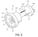
- FIG. 5is a perspective view illustrating the coupling between a body and a connector in an LED module for automobile headlights according to the present invention
- FIG. 6is a perspective view illustrating the coupling between a body and a lens in an LED module for automobile headlights according to the present invention
- FIG. 7is an exploded perspective view illustrating an automobile headlight having an LED module for automobile headlights according to the present invention.
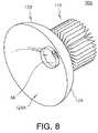
- FIG. 8is a perspective view illustrating an assembled structure of the automobile headlight shown in FIG. 7 .
- FIG. 1is a perspective view illustrating an LED module for automobile headlights according to the present invention
- FIG. 2is a sectional view of the LED module for automobile headlights taken along the line II—II of FIG. 1
- FIG. 3is an exploded view of FIG. 2 .
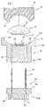
- an LED module 100 for automobile headlightsincludes a lighting unit or LED die 10 , a die base 20 for supporting the LED die 10 while guiding light from the LED die 10 in an upward direction, a cylindrical LED body 24 having the base 20 coupled with a central portion of a leading end 24 A thereof, a connector 34 coupled with a rear end 24 B of the LED module body 24 and having a portion electrically connected with the LED die 10 through the module body 24 , a transparent elastic encapsulant 48 for sealing the LED die 10 , the die base 20 and so on and a lens 56 coupled with the leading end 24 A of the module body 24 outside the elastic encapsulant 48 to protect the same.
- the module body 24is of a cylindrical member, and made of a metal of excellent thermal conductivity, and preferably, one selected from the group consisting of Al, Ag and Cu or a ceramic composite thereof.
- the module body 24 of this structurehas an excellent thermal conductivity in order to efficiently transmit heat generated from the LED die 10 , which is mounted on the leading end 24 A of the module body 24 , to a radiator 110 (which will be described later with reference to FIGS. 7 and 8 ).
- the module body 24is made of metal only, it can be formed by for example cutting a metal piece into a desired configuration.
- the module body 24may preferably have various cross-sections such as polygon and ellipse.
- the module body 24is radially expanded in a rim 30 that is formed at a predetermined position between the leading end 24 A and the rear end 24 B, and preferably, a vertical point (in the drawing) substantially corresponding to the bottom of the die base 20 .
- the rim 30functions to prevent the entire module body 24 from being inserted into a through hole 112 of the radiator 110 .
- the module body 24has an annular flange 26 formed around the leading end 24 A of the module body 24 and a concave recess 28 formed within the flange 26 , which imparts a generally cup-shaped structure to the module body 24 together with the annular flange 26 . Furthermore, inside the module body 24 , there are formed a pair of through holes 32 for receiving sheaths 36 , which support conductors 38 of the connector 34 to be described later while insulating the same. Alternatively, the module body 24 has a single through hole formed therein with a cable being inserted through the single hole.
- the die base 20is provided with a reflector 22 for seating the LED die 10 thereon.
- the reflector 22is also adapted to guide light from the LED die 10 in an upward direction.
- the die base 20is made of a metal such as Al and Ag which has high reflectivity and high thermal conductivity.
- the die basemay be made of a metal such as Cu having high thermal conductivity and excellent workability, and a high reflectivity metal such as Al, Ag and Pd may be plated or coated on the die base.
- the die base 20is made separately from the module body 24 and then coupled with the central portion of the leading end 24 A thereof, the die base 20 can be formed integrally with the module body 24 in case that the module body 24 is made of a metal having high workability such as Al, Ag and Cu. Of course, where the module body 24 is made of Cu, a high reflectivity metal such as Al, Ag and Pd is plated or coated on the die base 20 including the reflector 22 .
- the LED die 10is mounted on the die base 20 , and two examples of the LED die will be described in more detail with reference to FIG. 4 .
- the LED die 10includes a submount 14 mounted on the die base 20 and printed with a pattern (not shown), a plurality of LED chips 12 seated on the submount 14 in the form of flip chips and a plurality of solder bumps 16 for fixing the LED chips 12 to the submount 14 while electrically connecting the LED chips 12 to the pattern of the submount 14 .
- the solder bumps 16are made of a metal paste of excellent electric conductivity, and preferably, Au paste in order to have electric conductivity.
- the pattern of the submount 14is electrically connected with wires 40 extended from the conductors 38 so that external voltage supplied to the conductors 38 and the wires 40 of the connector 34 can be transmitted via the pattern of the submount 14 to the LED chips 12 seated on the submount 14 .
- the advantage of the submount 14is that the LED chips 12 can be seated on the submount 14 before mounting the submount 14 on the die base 20 so that the LED chips 12 of a small size can be arranged precisely.
- the submount 14is made of silicone, and preferably has a high thermal conductivity in order to effectively transmit heat from the chips 12 to the die base 20 underlying the submount 14 .
- the thermal conductivity necessary for the submount 14is preferably at least 100 W/m ⁇ K, and more preferably at least 200 W/m ⁇ K.
- the die base 20 and the module body 24 functioning as heat sinksare required to have preferably at least about 200 W/m ⁇ K.
- Alhas a thermal conductivity of about 237 W/m ⁇ K, Ag of about 429 W/m ⁇ K, Au of about 304 W/m ⁇ K and Cu of about 401 W/m ⁇ K.
- the submount 14is made of for example silicone having a predetermined value of elasticity in order to protect the LED chips 12 from external impact, which may damage the LED chips 12 if directly delivered to the chips 12 via the module body 24 and/or the die base 20 , thereby improving the reliability of a final product or the LED module 100 .
- the submount 14is optional, and therefore may be omitted by seating the LED chips 12 directly on the die base 20 , mounting the die base 20 on a central portion of the leading end 24 A of the module body 24 , and then electrically connecting the LED chips 12 with the wires 40 .
- the die base 20may be omitted also, in which a cup structure is formed in a central portion of the leading end 24 A of the module body 24 and the LED chips 12 are directly mounted on the cup structure.
- LED chips of about 3 to 5 Ware necessarily used at present to produce an output power of about 45 to 50 W in order to achieve a desired brightness for automobile headlights.
- the die base 20may be omitted since a few number of LED chips or even a single chip is expected to produce the above output power in the near future owing to the development of technology.
- the LED die 10 Aincludes a submount 14 A mounted on the die base 20 and having a pattern (not shown) printed thereon, a plurality of LED chips 12 A fixedly seated on the submount 14 A and wires 16 A for electrically connecting the LED chips 12 A with the pattern of the submount 14 A.
- the wires 16 Aare made of a metal having excellent electric conductivity since they are required to connect the LED chips 14 A together with only a low electric conductivity.
- the wires 16are preferably made of Au, which is especially excellent in workability and electric conductivity, since they are to be formed as fine as possible in order to minimize the shielding of light from the LED chips 12 A.
- the pattern of the submount 14 Ais electrically connected with the wires 40 extended from the conductors 38 of the connector 34 so that external voltage supplied to the conductors 38 and the wires 40 of the connector 34 is transmitted to the LED chips 12 A seated on the submount 14 A via the pattern of the submount 14 and the wires 16 A.
- modified LED die 10 Ais substantially the same as those of the above-described LED die 10 , and therefore will not be described in detail.
- the LED die 10 , 10 Ais mounted with the LED chips 12 , 12 A in a large number, a small number of chips or even a single chip can be adopted on condition that they or it can produce sufficient power.
- the LED chips 12 , 12 Amay include a number of RGB chips, in which three RGB chips emitting monochromatic light of different RGB colors are combined into one set, in order to radiate white light.
- white lightcan be produced from single-type LED chips for generating the same monochromatic light by coating fluorescent material on the chips or containing fluorescent material in the elastic encapsulant 48 .
- the connector 34is of a member made of insulating resin such as plastic, and formed preferably via injection molding.
- the sheaths 36are inserted into the through holes 32 of the module body 24 , respectively, and the connector 34 is coupled with the module body 24 via suitable coupling means such as adhesion so that the leading end 34 A of the connector 34 forms a sealing with the rear end 24 B of the module body 24 B.
- the leading end 34 A of the connector 34is sealingly coupled with the rear end 24 A of the module body 24 via suitable coupling means such as adhesion to prevent external moisture from permeating into the LED die 10 through gaps between the sheaths 36 and the through holes 32 .
- the sheaths 36may be formed in a diameter slightly larger than that of the through holes 32 to be press fit into the through holes 32 . This may prevent the permeation of external moisture while enhancing the coupling force between the module body 24 and the connector 34 .
- a pair of electrical connection units or sockets 42are provided in a rear end 34 B of the connector 34 , and each of the sockets 42 is provided with a jack or pin 44 for electrical connection.
- the sockets 42electrically connect the LED die 10 with external voltage via the conductors 36 and the wires 38 .
- the conductors 36 and the wires 40are made of a metal excellent in electric conductivity and workability such as Au, Ag and Cu.
- the wires 40are preferably made of Au, which is especially excellent in workability and electric conductivity, since they are to be formed as fine as possible in order to minimize the shielding of light emitted from the LED die 10 .
- the conductors 36 and the wires 40may be formed integrally, or separately to be coupled with each other adjacent to the tops of the sheaths 36 .
- the transparent elastic encapsulant 48is adapted to seal the LED die 10 , the die base 20 , the wires 40 , exposed upper portions of the conductors 36 and a portion of the concave recess 28 of the module body 24 surrounding the former from the outside.
- the elastic encapsulant 48is made of gel-like elastic resin such as silicone.
- the silicone-based resin materialhas excellent optical properties since it has high refractivity and is resistive to yellowing, that is, change in quality induced by single wavelength light. Unlike epoxy which is to be solidified, the silicone-based rein material still remains in a gel or elastomer state even after being cured, and thus can more stably protect the LED die 10 , 10 A, the wires 40 and the chips 12 , 12 A against thermal stress, vibration and external impact.
- the elastic encapsulant 48has a convex upper face 50 of a predetermined curvature and a convex lower face 52 corresponding to the concave recess 28 of the module body 24 .
- the elastic encapsulant 48is adapted to house the LED die 10 , the wires 40 and the die base 20 therein in a sealing fashion as represented with dotted lines 54 in FIG. 3 .
- the configuration of the elastic encapsulant 48 shown in FIG. 3indicates that in a final product of the LED module 100 .
- the elastic encapsulant 48maintains a certain degree of fluidity, while it is being processed rather than in the final state.
- the elastic encapsulant 48preferably contains UV absorbent, which serves to prevent the radiation of UV rays from the LED die 10 to the outside, and/or fluorescent material for adjusting the color of light.
- the fluorescent material for converting monochromatic light into white lightmay preferably adopt Tb-Al-Garnet (TAG), Yt-Al-Garnet (YAG) and so on.
- the UV absorbentmay adopt suitable fluorescent material that absorbs and converts UV rays into white light.
- the elastic encapsulant 48is covered with the lens 56 made of transparent plastic or epoxy.
- the lens 56is preferably sized so that its bottom periphery fits into the inside wall of the flange 26 .
- the bottom 60 of the lens 56is provided with a concave face therein having a curvature matching that of the convex upper face 50 of the elastic encapsulant 48 .
- the bottom 60is also provided with a convex face around the concave face thereof, and the convex face of the bottom 60 matches an engaging portion of the concave recess 28 of the module body 24 . While the top 58 of the lens 56 is illustrated angled from the side wall of the lens 56 , it may alternatively have various configurations such as a dome.
- the lens 56can be coupled with the leading end 24 A of the module body 24 via transfer molding of for example epoxy resin.
- the lens 56may be molded previously, and then attached to the leading end 24 A of the module body 24 via for example adhesive.
- the elastic encapsulant 48 and the lens 56may be replaced by an integral transparent encapsulant.
- the transparent encapsulantis formed via transfer molding of for example epoxy resin to function as a lens while sealing and protecting the LED die 10 , the wires 40 , the die base 20 and so on from the external environment.
- the transparent encalsulantpreferably has chemical and physical properties at least capable of blocking chemical or physical influence from the outside.
- the transparent encapsulantpreferably contains UV absorbent, which serves to prevent the radiation of UV rays from the LED die 10 , 10 A to the outside, and/or fluorescent material for adjusting the color of light.
- the fluorescent material for converting monochromatic light into white lightmay preferably adopt TAG, YAG and so on.
- the UV absorbentmay adopt suitable fluorescent material that absorbs and converts UV rays into white light.
- FIG. 5is a perspective view illustrating the coupling between a body and a connector in an LED module for automobile headlights according to the present invention
- FIG. 6is a perspective view illustrating the coupling between a body and a lens in an LED module for automobile headlights according to the present invention.
- a die base 20is mounted on a module body 24 , and an LED die 10 is mounted on the die base 20 .
- a connector 34is coupled with the module body 24 by inserting sheaths 36 into through holes 32 of the module body 24 and engaging a leading end 34 A of the connector 34 with a rear end 24 B of the module body 24 .
- one of the connectors 34is partially broken and wires 40 in the foregoing drawings are not shown for the sake of clarity.
- the wires 40are electrically connected with the LED die 10 .
- elastic resinsuch as silicone is dispensed onto the die base 20 , the LED die 10 , the wires 40 and a portion of a concave recess 28 of the module body 24 to form an elastic encapsulant 48 for sealing the same.
- a lens 56is coupled with the concave recess 28 of the module body leading end 24 A via transfer molding.
- a lens 56 containing a fluid elastic encapsulant 48may be coupled with the concave recess 28 of the module body leading end 24 A via a suitable technique such as adhesion. In this case, the lens 56 is turned over, and silicone resin is contained in the lens 56 , and then the module body 24 is coupled with the lens 56 from above.
- FIG. 7is an exploded perspective view illustrating an automobile headlight having an LED module for automobile headlights according to the present invention
- FIG. 8is a perspective view illustrating an assembled structure of the automobile headlight shown in FIG. 7 .
- the automobile headlight 200 of the present inventionincludes an LED module 100 , a lamp housing 124 for grasping a front portion of the LED module 100 including a lens 56 and a leading end of a module body 24 and functioning to guide light from the LED module 100 in a forward direction and a radiator 110 coupled with a rear periphery of the module body 24 to radiate heat from the module body 24 to the outside.
- the radiator 110is made of a material having an excellent thermal conductivity, and has a through hole 112 for receiving a rear part of the module body 24 , which is extended from the rim 30 (as shown in FIGS. 2 and 3 ) to the rear end 24 B, and a number of heat radiation fins 114 extended radially around the through hole 112 .
- the rear part of the module body 24is inserted into the through hole 112 and coupled therewith.
- the module body 24can be fixed to the radiator 110 via interference fit or with an additional fixing means.
- the module body 24can be screwed into the radiator 110 by forming a male thread in the rear part of the module body 24 and a female thread in the inside wall of the through hole 112 meshing with the male thread of the module body 24 .
- projections or groovesmay be provided in the rear end of the module body 24 or the connector 34 and hooks may be provided in a rear end of the heat radiator 110 corresponding to the former so that the projections or grooves are coupled with the hooks, respectively
- the lamp housing 124is provided with a shade 124 for guiding light from the LED module 100 in a forward direction, and a through hole 122 for receiving a front part of the LED module 100 .
- the through hole 122 of the lamp housing 124is provided with a step for preventing the LED module 100 from projecting beyond a front face 124 A of the lamp housing 124 to a predetermined degree when the front part of the lens 56 and the module body 24 are received in the through hole 122 .
- the step of the through hole 122allows the lens 56 to project from the front face 124 A of the lamp housing 124 while maintaining the flange in the front end 24 A of the module body 24 (as specifically shown in FIGS. 2 and 3 ) within the through hole 122 .
- the lamp housing 124may be made of various materials, and preferably a high reflectivity material.
- at least the front face 124is necessarily coated or plated with a high reflectivity material.
- an O-ring 130may be interposed between the lamp housing 124 and the LED module 100 in order to improve the sealing while enhancing the coupling therebetween.
- the O-ring 130is caught by the step of the through hole 122 and thereby coupled between the lamp housing 124 and the LED module 100 .
- locking meansmay be preferably provided in a rear end of the lamp housing 124 and a front end of the heat radiator 110 to detachably lock the lamp housing 124 with the heat radiator 110 .
- the locking meanscan adopt various structures well-known in the art, and therefore will not be described in detail.
- the present inventioncan supply external voltage to the LED chip or chips of the LED module via the connector in order to prevent the permeation of for example external moisture to the chips of chips inside the LED module.
- the module body supporting the LED dieis made of a high thermal conductivity material and the radiator is coupled around the module body in order to efficiently radiate heat from the LED die to the outside.
Landscapes
- Engineering & Computer Science (AREA)
- General Engineering & Computer Science (AREA)
- Physics & Mathematics (AREA)
- Microelectronics & Electronic Packaging (AREA)
- Optics & Photonics (AREA)
- Non-Portable Lighting Devices Or Systems Thereof (AREA)
- Led Device Packages (AREA)
- Arrangement Of Elements, Cooling, Sealing, Or The Like Of Lighting Devices (AREA)
Abstract
Description
Claims (21)
Applications Claiming Priority (2)
| Application Number | Priority Date | Filing Date | Title |
|---|---|---|---|
| KR1020040051001AKR100593919B1 (en) | 2004-07-01 | 2004-07-01 | LED module for vehicle headlight and vehicle headlight having same |
| KR2004-51001 | 2004-07-01 |
Publications (2)
| Publication Number | Publication Date |
|---|---|
| US20060002125A1 US20060002125A1 (en) | 2006-01-05 |
| US7128454B2true US7128454B2 (en) | 2006-10-31 |
Family
ID=35513688
Family Applications (1)
| Application Number | Title | Priority Date | Filing Date |
|---|---|---|---|
| US10/924,866Expired - LifetimeUS7128454B2 (en) | 2004-07-01 | 2004-08-25 | Light emitting diode module for automobile headlights and automobile headlight having the same |
Country Status (2)
| Country | Link |
|---|---|
| US (1) | US7128454B2 (en) |
| KR (1) | KR100593919B1 (en) |
Cited By (75)
| Publication number | Priority date | Publication date | Assignee | Title |
|---|---|---|---|---|
| US20060274529A1 (en)* | 2005-06-01 | 2006-12-07 | Cao Group, Inc. | LED light bulb |
| US20070132092A1 (en)* | 2005-12-09 | 2007-06-14 | Foxconn Technology Co., Ltd. | Light-emitting diode assembly and method of fabrication |
| US20070165408A1 (en)* | 2006-01-13 | 2007-07-19 | Chia-Mao Li | High-power LED package structure |
| US20070201233A1 (en)* | 2006-02-28 | 2007-08-30 | Yuji Sugiyama | Illumination Device |
| US20070230182A1 (en)* | 2006-03-28 | 2007-10-04 | Yun Tai | Led module |
| US20080025040A1 (en)* | 2006-07-25 | 2008-01-31 | Swantner Michael J | LED light engine |
| US20080042867A1 (en)* | 2006-08-21 | 2008-02-21 | Swantner Michael J | Illuminable indicator and light engine therefor |
| US20080062703A1 (en)* | 2001-08-24 | 2008-03-13 | Cao Group, Inc. | Light Bulb Utilizing a Replaceable LED Light Source |
| US20080124948A1 (en)* | 2006-11-26 | 2008-05-29 | Yu-Chu Lin | Connector Structure for a Vehicular Light |
| US20080158856A1 (en)* | 2006-12-28 | 2008-07-03 | Yu-Nung Shen | Light-emitting device with a long lifespan |
| US20080191227A1 (en)* | 2005-04-01 | 2008-08-14 | Matsushita Electric Industrial Co., Ltd. | Surface-Mount Type Optical Semiconductor Device and Method For Manufacturing Same |
| US20080298078A1 (en)* | 2007-05-30 | 2008-12-04 | Yamaha Hatsudoki Kabushiki Kaisha | Wiring arrangement for a vehicle |
| US20080316764A1 (en)* | 2005-11-17 | 2008-12-25 | Koninklijke Philips Electronics, N.V. | Lighting Device and Method for Directing Light |
| US20090161350A1 (en)* | 2007-12-21 | 2009-06-25 | Lumination Llc | Cool environment lamp with anti-fog component |
| US20090196064A1 (en)* | 2008-01-31 | 2009-08-06 | Honda Motor Co., Ltd | Vehicle lamp assembly |
| US20090196063A1 (en)* | 2008-01-31 | 2009-08-06 | Kracker Thomas G | Vehicle lamp assembly |
| US20090230893A1 (en)* | 2005-10-14 | 2009-09-17 | Patent-Treuhand-Gesellschaft Fur Elektrische Gluhlampen Mbh | Multifunctional Motor Vehicle Headlight Module, in Particular for the Front Region of a Motor Vehicle |
| US20090251889A1 (en)* | 2007-03-28 | 2009-10-08 | Glenn Bushee | Tactical lighting system |
| US20100096643A1 (en)* | 2001-08-24 | 2010-04-22 | Cao Group, Inc. | Semiconductor light source for illuminating a physical space including a 3-dimensional lead frame |
| US20100172124A1 (en)* | 2009-01-07 | 2010-07-08 | Cho Joo-Woan | Light source, light-emitting module having the same and backlight unit having the same |
| US20100187964A1 (en)* | 2008-05-01 | 2010-07-29 | Cao Group, Inc. | LED Lighting Device |
| US20100207502A1 (en)* | 2009-02-17 | 2010-08-19 | Densen Cao | LED Light Bulbs for Space Lighting |
| US20100226130A1 (en)* | 2009-03-04 | 2010-09-09 | Unilumin Group Co., Ltd. | Led light module for street lamp and method of manufacturing same |
| US20100224905A1 (en)* | 2001-08-24 | 2010-09-09 | Cao Group, Inc. | Semiconductor Light Source |
| US20100232173A1 (en)* | 2009-03-11 | 2010-09-16 | Masafumi Ohno | Vehicle headlight |
| US20100314641A1 (en)* | 2006-10-25 | 2010-12-16 | Hans-Joachim Schmidt | Lighting Device |
| US20110051432A1 (en)* | 2009-08-25 | 2011-03-03 | Heine Optotechnik Gmbh & Co Kg | LED Lamp |
| US7926975B2 (en) | 2007-12-21 | 2011-04-19 | Altair Engineering, Inc. | Light distribution using a light emitting diode assembly |
| US7938562B2 (en) | 2008-10-24 | 2011-05-10 | Altair Engineering, Inc. | Lighting including integral communication apparatus |
| US7946729B2 (en) | 2008-07-31 | 2011-05-24 | Altair Engineering, Inc. | Fluorescent tube replacement having longitudinally oriented LEDs |
| US7976196B2 (en) | 2008-07-09 | 2011-07-12 | Altair Engineering, Inc. | Method of forming LED-based light and resulting LED-based light |
| US20110199769A1 (en)* | 2010-02-17 | 2011-08-18 | Eric Bretschneider | Lighting unit with heat-dissipating chimney |
| US20110234082A1 (en)* | 2001-08-24 | 2011-09-29 | Cao Group, Inc. | Light bulb utilizing a replaceable led light source |
| US20110249406A1 (en)* | 2009-06-20 | 2011-10-13 | LEDAdventures LLC | Heat dissipation system for electrical components |
| US8118447B2 (en) | 2007-12-20 | 2012-02-21 | Altair Engineering, Inc. | LED lighting apparatus with swivel connection |
| US8214084B2 (en) | 2008-10-24 | 2012-07-03 | Ilumisys, Inc. | Integration of LED lighting with building controls |
| US8256924B2 (en) | 2008-09-15 | 2012-09-04 | Ilumisys, Inc. | LED-based light having rapidly oscillating LEDs |
| US8299695B2 (en) | 2009-06-02 | 2012-10-30 | Ilumisys, Inc. | Screw-in LED bulb comprising a base having outwardly projecting nodes |
| US20120300458A1 (en)* | 2005-04-08 | 2012-11-29 | Toshiba Lighting & Technology Corporation | Lamp Having Outer Shell to Radiate Heat of Light Source |
| US8324817B2 (en) | 2008-10-24 | 2012-12-04 | Ilumisys, Inc. | Light and light sensor |
| US8330381B2 (en) | 2009-05-14 | 2012-12-11 | Ilumisys, Inc. | Electronic circuit for DC conversion of fluorescent lighting ballast |
| US8362710B2 (en) | 2009-01-21 | 2013-01-29 | Ilumisys, Inc. | Direct AC-to-DC converter for passive component minimization and universal operation of LED arrays |
| US8360599B2 (en) | 2008-05-23 | 2013-01-29 | Ilumisys, Inc. | Electric shock resistant L.E.D. based light |
| US8421366B2 (en) | 2009-06-23 | 2013-04-16 | Ilumisys, Inc. | Illumination device including LEDs and a switching power control system |
| US8444292B2 (en) | 2008-10-24 | 2013-05-21 | Ilumisys, Inc. | End cap substitute for LED-based tube replacement light |
| US8454193B2 (en) | 2010-07-08 | 2013-06-04 | Ilumisys, Inc. | Independent modules for LED fluorescent light tube replacement |
| US8523394B2 (en) | 2010-10-29 | 2013-09-03 | Ilumisys, Inc. | Mechanisms for reducing risk of shock during installation of light tube |
| US8540401B2 (en) | 2010-03-26 | 2013-09-24 | Ilumisys, Inc. | LED bulb with internal heat dissipating structures |
| US8541958B2 (en) | 2010-03-26 | 2013-09-24 | Ilumisys, Inc. | LED light with thermoelectric generator |
| US8556452B2 (en) | 2009-01-15 | 2013-10-15 | Ilumisys, Inc. | LED lens |
| US8596813B2 (en) | 2010-07-12 | 2013-12-03 | Ilumisys, Inc. | Circuit board mount for LED light tube |
| US8653984B2 (en) | 2008-10-24 | 2014-02-18 | Ilumisys, Inc. | Integration of LED lighting control with emergency notification systems |
| US8664880B2 (en) | 2009-01-21 | 2014-03-04 | Ilumisys, Inc. | Ballast/line detection circuit for fluorescent replacement lamps |
| US8674626B2 (en) | 2008-09-02 | 2014-03-18 | Ilumisys, Inc. | LED lamp failure alerting system |
| US8870415B2 (en) | 2010-12-09 | 2014-10-28 | Ilumisys, Inc. | LED fluorescent tube replacement light with reduced shock hazard |
| US8901823B2 (en) | 2008-10-24 | 2014-12-02 | Ilumisys, Inc. | Light and light sensor |
| US9041808B2 (en) | 2012-03-08 | 2015-05-26 | Stanley Electric Co., Ltd. | Headlight controller, optical unit and vehicle headlight |
| US9057493B2 (en) | 2010-03-26 | 2015-06-16 | Ilumisys, Inc. | LED light tube with dual sided light distribution |
| US9072171B2 (en) | 2011-08-24 | 2015-06-30 | Ilumisys, Inc. | Circuit board mount for LED light |
| US9076952B2 (en) | 2013-01-16 | 2015-07-07 | Stanley Electric Co., Ltd. | Semiconductor light-emitting device |
| US9163794B2 (en) | 2012-07-06 | 2015-10-20 | Ilumisys, Inc. | Power supply assembly for LED-based light tube |
| US9184518B2 (en) | 2012-03-02 | 2015-11-10 | Ilumisys, Inc. | Electrical connector header for an LED-based light |
| US9224925B2 (en) | 2012-01-26 | 2015-12-29 | Stanley Electric Co., Ltd. | Semiconductor light-emitting device and manufacturing method |
| US9271367B2 (en) | 2012-07-09 | 2016-02-23 | Ilumisys, Inc. | System and method for controlling operation of an LED-based light |
| US9267650B2 (en) | 2013-10-09 | 2016-02-23 | Ilumisys, Inc. | Lens for an LED-based light |
| US9285084B2 (en) | 2013-03-14 | 2016-03-15 | Ilumisys, Inc. | Diffusers for LED-based lights |
| US20160085011A1 (en)* | 2014-09-24 | 2016-03-24 | Abtech Limited | Lighting Guide |
| KR20160103661A (en)* | 2015-02-25 | 2016-09-02 | 현대모비스 주식회사 | Lamp apparatus for an automobile |
| US9510400B2 (en) | 2014-05-13 | 2016-11-29 | Ilumisys, Inc. | User input systems for an LED-based light |
| US9574717B2 (en) | 2014-01-22 | 2017-02-21 | Ilumisys, Inc. | LED-based light with addressed LEDs |
| DE102015119513A1 (en)* | 2015-11-12 | 2017-05-18 | Dr. Ing. H.C. F. Porsche Aktiengesellschaft | Luminaire for a motor vehicle |
| US10161568B2 (en) | 2015-06-01 | 2018-12-25 | Ilumisys, Inc. | LED-based light with canted outer walls |
| US10948135B2 (en) | 2013-10-28 | 2021-03-16 | Next Lighting Corp. | Linear lighting apparatus |
| US11028989B2 (en) | 2019-11-13 | 2021-06-08 | James M. Aparo | Vehicle headlight device having an ejectable and replaceable lightbulb assembly |
| US11046235B2 (en) | 2019-11-13 | 2021-06-29 | James M. Aparo | Vehicle headlight assembly having an ejectable and replaceable lightbulb |
Families Citing this family (38)
| Publication number | Priority date | Publication date | Assignee | Title |
|---|---|---|---|---|
| US20060056203A1 (en)* | 2004-09-10 | 2006-03-16 | Taiwan Oasis Technology Co., Ltd. | LED luminance enhancing construction |
| JP2006244932A (en)* | 2005-03-04 | 2006-09-14 | Mutsuki Denki Kk | Reflector for projector light source |
| JP4761848B2 (en)* | 2005-06-22 | 2011-08-31 | 株式会社東芝 | Semiconductor light emitting device |
| SM200600005B (en)* | 2006-02-15 | 2007-08-22 | Idealed.It S R L | High power LED light unit, as well as lighting apparatus comprising this unit |
| WO2007130357A2 (en) | 2006-05-02 | 2007-11-15 | Superbulbs, Inc. | Method of light dispersion and preferential scattering of certain wavelengths of light for light-emitting diodes and bulbs constructed therefrom |
| WO2007130358A2 (en)* | 2006-05-02 | 2007-11-15 | Superbulbs, Inc. | Plastic led bulb |
| KR100754405B1 (en) | 2006-06-01 | 2007-08-31 | 삼성전자주식회사 | Lighting fixtures |
| TWI321857B (en)* | 2006-07-21 | 2010-03-11 | Epistar Corp | A light emitting device |
| EP1898144A3 (en)* | 2006-09-08 | 2010-08-25 | Robert Bosch Gmbh | Lighting device with several LED components and method for its manufacture |
| WO2008100124A1 (en)* | 2007-02-12 | 2008-08-21 | Laura Patricia Vargas Maciel | High-power led lamp for street lighting |
| USD593964S1 (en)* | 2007-06-06 | 2009-06-09 | Lw Scientific, Inc. | LED lateral illuminator for microscope |
| US7762829B2 (en)* | 2007-12-27 | 2010-07-27 | Tyco Electronics Corporation | Connector assembly for termination of miniature electronics |
| US8018136B2 (en)* | 2008-02-28 | 2011-09-13 | Tyco Electronics Corporation | Integrated LED driver for LED socket |
| ITUD20080076A1 (en)* | 2008-04-08 | 2009-10-09 | Gpe Srl | LIGHTING DEVICE, AND ITS MANUFACTURING PROCEDURE |
| US7800909B2 (en)* | 2008-10-27 | 2010-09-21 | Edison Opto Corporation | Lamp base having a heat sink |
| DE202008017960U1 (en)* | 2008-12-17 | 2011-02-10 | Poly-Tech Service Gmbh | LED-based lighting system |
| DE202009000236U1 (en)* | 2009-01-09 | 2010-06-17 | Ledon Lighting Jennersdorf Gmbh | Housed LED module |
| DE102009005547A1 (en)* | 2009-01-20 | 2010-07-29 | R. Stahl Schaltgeräte GmbH | Encapsulated light-emitting diode arrangement |
| DE202009013278U1 (en)* | 2009-04-24 | 2010-09-16 | Ledon Lighting Jennersdorf Gmbh | Housed LED module with integrated electronics |
| KR101007134B1 (en) | 2009-06-05 | 2011-01-10 | 엘지이노텍 주식회사 | Lighting device |
| FR2947033B1 (en)* | 2009-06-22 | 2012-06-01 | Blachere Illumination | DECORATION GUIRLANDE LAMP COMPRISING A POWER LIGHT EMITTING DIODE AND DECORATION GUIRLANDE EQUIPPED WITH SUCH LAMPS |
| DE102010002235A1 (en)* | 2010-02-23 | 2011-08-25 | Zumtobel Lighting GmbH, 32657 | Heat sink for a light source |
| US20130170233A1 (en)* | 2010-07-16 | 2013-07-04 | Toshiba Lighting & Technology Corporation | Lamp device and lighting apparatus |
| DE102011004086C5 (en)* | 2011-02-14 | 2016-07-14 | Automotive Lighting Reutlingen Gmbh | Method for producing a color-correcting projection optics |
| TW201333373A (en)* | 2012-02-07 | 2013-08-16 | Gem Weltronics Twn Corp | Integrated multi-layer lighting device |
| KR101461620B1 (en)* | 2012-09-05 | 2014-12-04 | 안정오 | Led lamp |
| CN102927540B (en)* | 2012-11-02 | 2014-09-03 | 阳江纳谷科技有限公司 | Device, method and system for modular light emitting diode circuit assembly |
| JP2014107229A (en)* | 2012-11-29 | 2014-06-09 | Toshiba Lighting & Technology Corp | Light emitting device and lighting device for vehicle |
| DE102013207156A1 (en) | 2013-04-19 | 2014-10-23 | Adidas Ag | Shoe, in particular a sports shoe |
| FR3012204B1 (en)* | 2013-10-18 | 2015-10-30 | Valeo Vision | SYSTEM FOR ELECTRICALLY CONNECTING AT LEAST ONE LIGHT SOURCE TO AN ELECTRICAL POWER SUPPLY SYSTEM |
| JP6467206B2 (en)* | 2014-01-28 | 2019-02-06 | 株式会社小糸製作所 | Light source unit |
| US9709727B2 (en)* | 2014-02-24 | 2017-07-18 | Tyco Electronics Canada Ulc | Light assembly with conforming seal |
| JP6464697B2 (en)* | 2014-11-27 | 2019-02-06 | 東芝ライテック株式会社 | LIGHTING DEVICE FOR VEHICLE AND LIGHT |
| FR3039885B1 (en)* | 2015-08-06 | 2022-06-24 | Valeo Iluminacion Sa | HEAT SINK FOR MOTOR VEHICLE OPTICAL MODULE |
| WO2017111714A1 (en)* | 2015-12-23 | 2017-06-29 | LIERDE Jan Herman Ida Elizabeth VAN | Lighting fixture |
| CN206247200U (en)* | 2016-11-22 | 2017-06-13 | 深圳北极之光科技有限公司 | automobile LED headlight |
| JP6944660B2 (en)* | 2018-02-27 | 2021-10-06 | 東芝ライテック株式会社 | Vehicle lighting equipment and vehicle lighting equipment |
| JP7492189B2 (en)* | 2019-11-28 | 2024-05-29 | 東芝ライテック株式会社 | Vehicle lighting device and vehicle lamp |
Citations (9)
| Publication number | Priority date | Publication date | Assignee | Title |
|---|---|---|---|---|
| US3508100A (en)* | 1966-12-28 | 1970-04-21 | Philips Corp | Electroluminescent semiconductor devices |
| US3818215A (en)* | 1972-02-25 | 1974-06-18 | Bosch Gmbh Robert | Sealed-beam headlight |
| US5720548A (en)* | 1995-11-14 | 1998-02-24 | Progressive Technology In Lighting, Inc. | High luminance fluorescent lamp assembly |
| US5991160A (en)* | 1995-12-27 | 1999-11-23 | Infineon Technologies Corporation | Surface mount LED alphanumeric display |
| KR20020050584A (en) | 2000-12-21 | 2002-06-27 | 김영삼 | Removable Flashlight Using High Brightness Light Emitting Diode |
| US6476549B2 (en)* | 2000-10-26 | 2002-11-05 | Mu-Chin Yu | Light emitting diode with improved heat dissipation |
| US6479759B2 (en)* | 2000-07-19 | 2002-11-12 | Alcatel | Submount, electronic assembly and process for producing the same |
| US6498355B1 (en)* | 2001-10-09 | 2002-12-24 | Lumileds Lighting, U.S., Llc | High flux LED array |
| KR200331783Y1 (en) | 2003-07-18 | 2003-11-01 | 이동철 | Automotive LED bulb |
- 2004
- 2004-07-01KRKR1020040051001Apatent/KR100593919B1/ennot_activeExpired - Fee Related
- 2004-08-25USUS10/924,866patent/US7128454B2/ennot_activeExpired - Lifetime
Patent Citations (9)
| Publication number | Priority date | Publication date | Assignee | Title |
|---|---|---|---|---|
| US3508100A (en)* | 1966-12-28 | 1970-04-21 | Philips Corp | Electroluminescent semiconductor devices |
| US3818215A (en)* | 1972-02-25 | 1974-06-18 | Bosch Gmbh Robert | Sealed-beam headlight |
| US5720548A (en)* | 1995-11-14 | 1998-02-24 | Progressive Technology In Lighting, Inc. | High luminance fluorescent lamp assembly |
| US5991160A (en)* | 1995-12-27 | 1999-11-23 | Infineon Technologies Corporation | Surface mount LED alphanumeric display |
| US6479759B2 (en)* | 2000-07-19 | 2002-11-12 | Alcatel | Submount, electronic assembly and process for producing the same |
| US6476549B2 (en)* | 2000-10-26 | 2002-11-05 | Mu-Chin Yu | Light emitting diode with improved heat dissipation |
| KR20020050584A (en) | 2000-12-21 | 2002-06-27 | 김영삼 | Removable Flashlight Using High Brightness Light Emitting Diode |
| US6498355B1 (en)* | 2001-10-09 | 2002-12-24 | Lumileds Lighting, U.S., Llc | High flux LED array |
| KR200331783Y1 (en) | 2003-07-18 | 2003-11-01 | 이동철 | Automotive LED bulb |
Cited By (154)
| Publication number | Priority date | Publication date | Assignee | Title |
|---|---|---|---|---|
| US7976211B2 (en) | 2001-08-24 | 2011-07-12 | Densen Cao | Light bulb utilizing a replaceable LED light source |
| US20110234082A1 (en)* | 2001-08-24 | 2011-09-29 | Cao Group, Inc. | Light bulb utilizing a replaceable led light source |
| US8201985B2 (en) | 2001-08-24 | 2012-06-19 | Cao Group, Inc. | Light bulb utilizing a replaceable LED light source |
| US9761775B2 (en) | 2001-08-24 | 2017-09-12 | Epistar Corporation | Semiconductor light source |
| US8569785B2 (en) | 2001-08-24 | 2013-10-29 | Cao Group, Inc. | Semiconductor light source for illuminating a physical space including a 3-dimensional lead frame |
| US20100224905A1 (en)* | 2001-08-24 | 2010-09-09 | Cao Group, Inc. | Semiconductor Light Source |
| US8723212B2 (en) | 2001-08-24 | 2014-05-13 | Cao Group, Inc. | Semiconductor light source |
| US20080062703A1 (en)* | 2001-08-24 | 2008-03-13 | Cao Group, Inc. | Light Bulb Utilizing a Replaceable LED Light Source |
| US8882334B2 (en) | 2001-08-24 | 2014-11-11 | Cao Group, Inc. | Light bulb utilizing a replaceable LED light source |
| US20100096643A1 (en)* | 2001-08-24 | 2010-04-22 | Cao Group, Inc. | Semiconductor light source for illuminating a physical space including a 3-dimensional lead frame |
| US7867794B2 (en) | 2005-04-01 | 2011-01-11 | Panasonic Corporation | Surface-mount type optical semiconductor device and method for manufacturing the same |
| US20080191227A1 (en)* | 2005-04-01 | 2008-08-14 | Matsushita Electric Industrial Co., Ltd. | Surface-Mount Type Optical Semiconductor Device and Method For Manufacturing Same |
| US7705465B2 (en)* | 2005-04-01 | 2010-04-27 | Panasonic Corporation | Surface-mount type optical semiconductor device and method for manufacturing the same |
| US20100159621A1 (en)* | 2005-04-01 | 2010-06-24 | Panasonic Corporation | Surface-mount type optical semiconductor device and method for manufacturing the same |
| US9249967B2 (en) | 2005-04-08 | 2016-02-02 | Toshiba Lighting & Technology Corporation | Lamp having outer shell to radiate heat of light source |
| US8979315B2 (en)* | 2005-04-08 | 2015-03-17 | Toshiba Lighting & Technology Corporation | Lamp having outer shell to radiate heat of light source |
| US9103541B2 (en) | 2005-04-08 | 2015-08-11 | Toshiba Lighting & Technology Corporation | Lamp having outer shell to radiate heat of light source |
| US8858041B2 (en) | 2005-04-08 | 2014-10-14 | Toshiba Lighting & Technology Corporation | Lamp having outer shell to radiate heat of light source |
| US9234657B2 (en) | 2005-04-08 | 2016-01-12 | Toshiba Lighting & Technology Corporation | Lamp having outer shell to radiate heat of light source |
| US9080759B2 (en) | 2005-04-08 | 2015-07-14 | Toshiba Lighting & Technology Corporation | Lamp having outer shell to radiate heat of light source |
| US9772098B2 (en) | 2005-04-08 | 2017-09-26 | Toshiba Lighting & Technology Corporation | Lamp having outer shell to radiate heat of light source |
| US8992041B2 (en) | 2005-04-08 | 2015-03-31 | Toshiba Lighting & Technology Corporation | Lamp having outer shell to radiate heat of light source |
| US20120300458A1 (en)* | 2005-04-08 | 2012-11-29 | Toshiba Lighting & Technology Corporation | Lamp Having Outer Shell to Radiate Heat of Light Source |
| US20060274529A1 (en)* | 2005-06-01 | 2006-12-07 | Cao Group, Inc. | LED light bulb |
| US20090230893A1 (en)* | 2005-10-14 | 2009-09-17 | Patent-Treuhand-Gesellschaft Fur Elektrische Gluhlampen Mbh | Multifunctional Motor Vehicle Headlight Module, in Particular for the Front Region of a Motor Vehicle |
| US7982403B2 (en)* | 2005-10-14 | 2011-07-19 | Osram Gesellschaft Mit Beschraenkter Haftung | Multifunctional motor vehicle headlight module, in particular for the front region of a motor vehicle |
| US20080316764A1 (en)* | 2005-11-17 | 2008-12-25 | Koninklijke Philips Electronics, N.V. | Lighting Device and Method for Directing Light |
| US7798691B2 (en)* | 2005-11-17 | 2010-09-21 | Koninklijke Philips Electronics N.V. | Lighting device and method for directing light |
| US7598535B2 (en)* | 2005-12-09 | 2009-10-06 | Foxconn Technology Co., Ltd. | Light-emitting diode assembly and method of fabrication |
| US20070132092A1 (en)* | 2005-12-09 | 2007-06-14 | Foxconn Technology Co., Ltd. | Light-emitting diode assembly and method of fabrication |
| US20070165408A1 (en)* | 2006-01-13 | 2007-07-19 | Chia-Mao Li | High-power LED package structure |
| US7465069B2 (en)* | 2006-01-13 | 2008-12-16 | Chia-Mao Li | High-power LED package structure |
| US7658511B2 (en)* | 2006-02-28 | 2010-02-09 | Stanley Electric Co., Ltd. | Illumination device with reflective heat radiating fins |
| US20070201233A1 (en)* | 2006-02-28 | 2007-08-30 | Yuji Sugiyama | Illumination Device |
| US20070230182A1 (en)* | 2006-03-28 | 2007-10-04 | Yun Tai | Led module |
| US20080025040A1 (en)* | 2006-07-25 | 2008-01-31 | Swantner Michael J | LED light engine |
| US7753540B2 (en)* | 2006-08-21 | 2010-07-13 | Osram Sylvania Inc. | Illuminable indicator and light engine therefor |
| US20080042867A1 (en)* | 2006-08-21 | 2008-02-21 | Swantner Michael J | Illuminable indicator and light engine therefor |
| US20100314641A1 (en)* | 2006-10-25 | 2010-12-16 | Hans-Joachim Schmidt | Lighting Device |
| US20080124948A1 (en)* | 2006-11-26 | 2008-05-29 | Yu-Chu Lin | Connector Structure for a Vehicular Light |
| US20080158856A1 (en)* | 2006-12-28 | 2008-07-03 | Yu-Nung Shen | Light-emitting device with a long lifespan |
| US20100135001A1 (en)* | 2006-12-28 | 2010-06-03 | Yu-Nung Shen | Light-emitting device with a long lifespan |
| US7926986B2 (en) | 2006-12-28 | 2011-04-19 | Yu-Nung Shen | Light-emitting device with a long lifespan |
| US20100133973A1 (en)* | 2006-12-28 | 2010-06-03 | Yu-Nung Shen | Light-emitting device with a long lifespan |
| US7682053B2 (en)* | 2006-12-28 | 2010-03-23 | Yu-Nung Shen | Light-emitting device with a long lifespan |
| US8152323B2 (en)* | 2007-03-28 | 2012-04-10 | Glenn Bushee | Tactical lighting system |
| US20090251889A1 (en)* | 2007-03-28 | 2009-10-08 | Glenn Bushee | Tactical lighting system |
| US8044532B2 (en)* | 2007-05-30 | 2011-10-25 | Yamaha Hatsudoki Kabushiki Kaisha | Wiring arrangement for a vehicle |
| US20080298078A1 (en)* | 2007-05-30 | 2008-12-04 | Yamaha Hatsudoki Kabushiki Kaisha | Wiring arrangement for a vehicle |
| US8928025B2 (en) | 2007-12-20 | 2015-01-06 | Ilumisys, Inc. | LED lighting apparatus with swivel connection |
| US8118447B2 (en) | 2007-12-20 | 2012-02-21 | Altair Engineering, Inc. | LED lighting apparatus with swivel connection |
| US7926975B2 (en) | 2007-12-21 | 2011-04-19 | Altair Engineering, Inc. | Light distribution using a light emitting diode assembly |
| US7766497B2 (en)* | 2007-12-21 | 2010-08-03 | Lumination Llc | Cool environment lamp with anti-fog component |
| US20090161350A1 (en)* | 2007-12-21 | 2009-06-25 | Lumination Llc | Cool environment lamp with anti-fog component |
| US7841756B2 (en) | 2008-01-31 | 2010-11-30 | Honda Motor Co., Ltd. | Vehicle lamp assembly |
| US7625110B2 (en) | 2008-01-31 | 2009-12-01 | Honda Motor Co., Ltd. | Vehicle lamp assembly |
| US20090196064A1 (en)* | 2008-01-31 | 2009-08-06 | Honda Motor Co., Ltd | Vehicle lamp assembly |
| US20090196063A1 (en)* | 2008-01-31 | 2009-08-06 | Kracker Thomas G | Vehicle lamp assembly |
| US20100187964A1 (en)* | 2008-05-01 | 2010-07-29 | Cao Group, Inc. | LED Lighting Device |
| US8465179B2 (en) | 2008-05-01 | 2013-06-18 | Cao Group, Inc. | LED lighting device |
| US7963667B2 (en) | 2008-05-01 | 2011-06-21 | Stan Thurgood | LED lighting device |
| US8360599B2 (en) | 2008-05-23 | 2013-01-29 | Ilumisys, Inc. | Electric shock resistant L.E.D. based light |
| US8807785B2 (en) | 2008-05-23 | 2014-08-19 | Ilumisys, Inc. | Electric shock resistant L.E.D. based light |
| US7976196B2 (en) | 2008-07-09 | 2011-07-12 | Altair Engineering, Inc. | Method of forming LED-based light and resulting LED-based light |
| US7946729B2 (en) | 2008-07-31 | 2011-05-24 | Altair Engineering, Inc. | Fluorescent tube replacement having longitudinally oriented LEDs |
| US8674626B2 (en) | 2008-09-02 | 2014-03-18 | Ilumisys, Inc. | LED lamp failure alerting system |
| US8256924B2 (en) | 2008-09-15 | 2012-09-04 | Ilumisys, Inc. | LED-based light having rapidly oscillating LEDs |
| US9585216B2 (en) | 2008-10-24 | 2017-02-28 | Ilumisys, Inc. | Integration of LED lighting with building controls |
| US10182480B2 (en) | 2008-10-24 | 2019-01-15 | Ilumisys, Inc. | Light and light sensor |
| US10342086B2 (en) | 2008-10-24 | 2019-07-02 | Ilumisys, Inc. | Integration of LED lighting with building controls |
| US8444292B2 (en) | 2008-10-24 | 2013-05-21 | Ilumisys, Inc. | End cap substitute for LED-based tube replacement light |
| US11333308B2 (en) | 2008-10-24 | 2022-05-17 | Ilumisys, Inc. | Light and light sensor |
| US8324817B2 (en) | 2008-10-24 | 2012-12-04 | Ilumisys, Inc. | Light and light sensor |
| US9635727B2 (en) | 2008-10-24 | 2017-04-25 | Ilumisys, Inc. | Light and light sensor |
| US11073275B2 (en) | 2008-10-24 | 2021-07-27 | Ilumisys, Inc. | Lighting including integral communication apparatus |
| US9398661B2 (en) | 2008-10-24 | 2016-07-19 | Ilumisys, Inc. | Light and light sensor |
| US10973094B2 (en) | 2008-10-24 | 2021-04-06 | Ilumisys, Inc. | Integration of LED lighting with building controls |
| US8946996B2 (en) | 2008-10-24 | 2015-02-03 | Ilumisys, Inc. | Light and light sensor |
| US8251544B2 (en) | 2008-10-24 | 2012-08-28 | Ilumisys, Inc. | Lighting including integral communication apparatus |
| US10036549B2 (en) | 2008-10-24 | 2018-07-31 | Ilumisys, Inc. | Lighting including integral communication apparatus |
| US10932339B2 (en) | 2008-10-24 | 2021-02-23 | Ilumisys, Inc. | Light and light sensor |
| US8653984B2 (en) | 2008-10-24 | 2014-02-18 | Ilumisys, Inc. | Integration of LED lighting control with emergency notification systems |
| US7938562B2 (en) | 2008-10-24 | 2011-05-10 | Altair Engineering, Inc. | Lighting including integral communication apparatus |
| US8901823B2 (en) | 2008-10-24 | 2014-12-02 | Ilumisys, Inc. | Light and light sensor |
| US9101026B2 (en) | 2008-10-24 | 2015-08-04 | Ilumisys, Inc. | Integration of LED lighting with building controls |
| US10560992B2 (en) | 2008-10-24 | 2020-02-11 | Ilumisys, Inc. | Light and light sensor |
| US10176689B2 (en) | 2008-10-24 | 2019-01-08 | Ilumisys, Inc. | Integration of led lighting control with emergency notification systems |
| US9353939B2 (en) | 2008-10-24 | 2016-05-31 | iLumisys, Inc | Lighting including integral communication apparatus |
| US8214084B2 (en) | 2008-10-24 | 2012-07-03 | Ilumisys, Inc. | Integration of LED lighting with building controls |
| US10713915B2 (en) | 2008-10-24 | 2020-07-14 | Ilumisys, Inc. | Integration of LED lighting control with emergency notification systems |
| US10571115B2 (en) | 2008-10-24 | 2020-02-25 | Ilumisys, Inc. | Lighting including integral communication apparatus |
| US8684550B2 (en)* | 2009-01-07 | 2014-04-01 | Samsung Display Co., Ltd. | Light source, light-emitting module having the same and backlight unit have the same |
| US20100172124A1 (en)* | 2009-01-07 | 2010-07-08 | Cho Joo-Woan | Light source, light-emitting module having the same and backlight unit having the same |
| US8556452B2 (en) | 2009-01-15 | 2013-10-15 | Ilumisys, Inc. | LED lens |
| US8664880B2 (en) | 2009-01-21 | 2014-03-04 | Ilumisys, Inc. | Ballast/line detection circuit for fluorescent replacement lamps |
| US8362710B2 (en) | 2009-01-21 | 2013-01-29 | Ilumisys, Inc. | Direct AC-to-DC converter for passive component minimization and universal operation of LED arrays |
| US20100207502A1 (en)* | 2009-02-17 | 2010-08-19 | Densen Cao | LED Light Bulbs for Space Lighting |
| US8653723B2 (en) | 2009-02-17 | 2014-02-18 | Cao Group, Inc. | LED light bulbs for space lighting |
| US20100226130A1 (en)* | 2009-03-04 | 2010-09-09 | Unilumin Group Co., Ltd. | Led light module for street lamp and method of manufacturing same |
| US8293548B2 (en)* | 2009-03-04 | 2012-10-23 | Unilumin Group Co., Ltd. | LED light module for street lamp and method of manufacturing same |
| US8556480B2 (en)* | 2009-03-11 | 2013-10-15 | Stanley Electric Co., Ltd. | Vehicle headlight |
| US20100232173A1 (en)* | 2009-03-11 | 2010-09-16 | Masafumi Ohno | Vehicle headlight |
| US8251560B2 (en)* | 2009-03-11 | 2012-08-28 | Stanley Electric Co., Ltd. | Vehicle headlight |
| US8330381B2 (en) | 2009-05-14 | 2012-12-11 | Ilumisys, Inc. | Electronic circuit for DC conversion of fluorescent lighting ballast |
| US8299695B2 (en) | 2009-06-02 | 2012-10-30 | Ilumisys, Inc. | Screw-in LED bulb comprising a base having outwardly projecting nodes |
| US20110249406A1 (en)* | 2009-06-20 | 2011-10-13 | LEDAdventures LLC | Heat dissipation system for electrical components |
| US8421366B2 (en) | 2009-06-23 | 2013-04-16 | Ilumisys, Inc. | Illumination device including LEDs and a switching power control system |
| US20110051432A1 (en)* | 2009-08-25 | 2011-03-03 | Heine Optotechnik Gmbh & Co Kg | LED Lamp |
| US8684566B2 (en) | 2010-02-17 | 2014-04-01 | Next Lighting, Corp. | Lighting unit with indirect light source |
| US8491165B2 (en) | 2010-02-17 | 2013-07-23 | Next Lighting Corp. | Lighting unit having lighting strips with light emitting elements and a remote luminescent material |
| US8360607B2 (en)* | 2010-02-17 | 2013-01-29 | Next Lighting Corp. | Lighting unit with heat-dissipating chimney |
| US20110199005A1 (en)* | 2010-02-17 | 2011-08-18 | Eric Bretschneider | Lighting unit having lighting strips with light emitting elements and a remote luminescent material |
| US20110199769A1 (en)* | 2010-02-17 | 2011-08-18 | Eric Bretschneider | Lighting unit with heat-dissipating chimney |
| US8540401B2 (en) | 2010-03-26 | 2013-09-24 | Ilumisys, Inc. | LED bulb with internal heat dissipating structures |
| US8840282B2 (en) | 2010-03-26 | 2014-09-23 | Ilumisys, Inc. | LED bulb with internal heat dissipating structures |
| US9057493B2 (en) | 2010-03-26 | 2015-06-16 | Ilumisys, Inc. | LED light tube with dual sided light distribution |
| US9013119B2 (en) | 2010-03-26 | 2015-04-21 | Ilumisys, Inc. | LED light with thermoelectric generator |
| US9395075B2 (en) | 2010-03-26 | 2016-07-19 | Ilumisys, Inc. | LED bulb for incandescent bulb replacement with internal heat dissipating structures |
| US8541958B2 (en) | 2010-03-26 | 2013-09-24 | Ilumisys, Inc. | LED light with thermoelectric generator |
| US8454193B2 (en) | 2010-07-08 | 2013-06-04 | Ilumisys, Inc. | Independent modules for LED fluorescent light tube replacement |
| US8596813B2 (en) | 2010-07-12 | 2013-12-03 | Ilumisys, Inc. | Circuit board mount for LED light tube |
| US8894430B2 (en) | 2010-10-29 | 2014-11-25 | Ilumisys, Inc. | Mechanisms for reducing risk of shock during installation of light tube |
| US8523394B2 (en) | 2010-10-29 | 2013-09-03 | Ilumisys, Inc. | Mechanisms for reducing risk of shock during installation of light tube |
| US8870415B2 (en) | 2010-12-09 | 2014-10-28 | Ilumisys, Inc. | LED fluorescent tube replacement light with reduced shock hazard |
| US9072171B2 (en) | 2011-08-24 | 2015-06-30 | Ilumisys, Inc. | Circuit board mount for LED light |
| US9224925B2 (en) | 2012-01-26 | 2015-12-29 | Stanley Electric Co., Ltd. | Semiconductor light-emitting device and manufacturing method |
| US9184518B2 (en) | 2012-03-02 | 2015-11-10 | Ilumisys, Inc. | Electrical connector header for an LED-based light |
| US9041808B2 (en) | 2012-03-08 | 2015-05-26 | Stanley Electric Co., Ltd. | Headlight controller, optical unit and vehicle headlight |
| US9163794B2 (en) | 2012-07-06 | 2015-10-20 | Ilumisys, Inc. | Power supply assembly for LED-based light tube |
| US10278247B2 (en) | 2012-07-09 | 2019-04-30 | Ilumisys, Inc. | System and method for controlling operation of an LED-based light |
| US9807842B2 (en) | 2012-07-09 | 2017-10-31 | Ilumisys, Inc. | System and method for controlling operation of an LED-based light |
| US9271367B2 (en) | 2012-07-09 | 2016-02-23 | Ilumisys, Inc. | System and method for controlling operation of an LED-based light |
| US10966295B2 (en) | 2012-07-09 | 2021-03-30 | Ilumisys, Inc. | System and method for controlling operation of an LED-based light |
| US9076952B2 (en) | 2013-01-16 | 2015-07-07 | Stanley Electric Co., Ltd. | Semiconductor light-emitting device |
| US9285084B2 (en) | 2013-03-14 | 2016-03-15 | Ilumisys, Inc. | Diffusers for LED-based lights |
| US9267650B2 (en) | 2013-10-09 | 2016-02-23 | Ilumisys, Inc. | Lens for an LED-based light |
| US10948135B2 (en) | 2013-10-28 | 2021-03-16 | Next Lighting Corp. | Linear lighting apparatus |
| US12385606B2 (en) | 2013-10-28 | 2025-08-12 | Satco Products, Inc. | Linear lamp replacement |
| US11767951B2 (en) | 2013-10-28 | 2023-09-26 | Satco Products, Inc. | Linear lamp replacement |
| US9574717B2 (en) | 2014-01-22 | 2017-02-21 | Ilumisys, Inc. | LED-based light with addressed LEDs |
| US10260686B2 (en) | 2014-01-22 | 2019-04-16 | Ilumisys, Inc. | LED-based light with addressed LEDs |
| US9510400B2 (en) | 2014-05-13 | 2016-11-29 | Ilumisys, Inc. | User input systems for an LED-based light |
| US20160085011A1 (en)* | 2014-09-24 | 2016-03-24 | Abtech Limited | Lighting Guide |
| US9507070B2 (en)* | 2014-09-24 | 2016-11-29 | Abtech Limited | Lighting guide |
| KR102339518B1 (en) | 2015-02-25 | 2021-12-16 | 현대모비스 주식회사 | Lamp apparatus for an automobile |
| KR20160103661A (en)* | 2015-02-25 | 2016-09-02 | 현대모비스 주식회사 | Lamp apparatus for an automobile |
| US11028972B2 (en) | 2015-06-01 | 2021-06-08 | Ilumisys, Inc. | LED-based light with canted outer walls |
| US10161568B2 (en) | 2015-06-01 | 2018-12-25 | Ilumisys, Inc. | LED-based light with canted outer walls |
| US11428370B2 (en) | 2015-06-01 | 2022-08-30 | Ilumisys, Inc. | LED-based light with canted outer walls |
| US10690296B2 (en) | 2015-06-01 | 2020-06-23 | Ilumisys, Inc. | LED-based light with canted outer walls |
| DE102015119513B4 (en) | 2015-11-12 | 2021-10-21 | Dr. Ing. H.C. F. Porsche Aktiengesellschaft | Light for a motor vehicle |
| DE102015119513A1 (en)* | 2015-11-12 | 2017-05-18 | Dr. Ing. H.C. F. Porsche Aktiengesellschaft | Luminaire for a motor vehicle |
| US11046235B2 (en) | 2019-11-13 | 2021-06-29 | James M. Aparo | Vehicle headlight assembly having an ejectable and replaceable lightbulb |
| US11028989B2 (en) | 2019-11-13 | 2021-06-08 | James M. Aparo | Vehicle headlight device having an ejectable and replaceable lightbulb assembly |
Also Published As
| Publication number | Publication date |
|---|---|
| US20060002125A1 (en) | 2006-01-05 |
| KR20060002092A (en) | 2006-01-09 |
| KR100593919B1 (en) | 2006-06-30 |
Similar Documents
| Publication | Publication Date | Title |
|---|---|---|
| US7128454B2 (en) | Light emitting diode module for automobile headlights and automobile headlight having the same | |
| TWI462251B (en) | Lead frame with heat sink support, manufacturing method of light emitting diode package using same, and light emitting diode package manufactured by the same | |
| TWI238542B (en) | High power light emitting diode | |
| US8337214B2 (en) | Electrical connectors and light emitting device package and methods of assembling the same | |
| US7367692B2 (en) | Light bulb having surfaces for reflecting light produced by electronic light generating sources | |
| US8840265B2 (en) | Illumination apparatus employing light-emitting device package | |
| US20140218892A1 (en) | Wide emission angle led package with remote phosphor component | |
| US20070030676A1 (en) | Light-emitting module and light-emitting unit | |
| US11326743B2 (en) | LED light apparatus | |
| US9231176B2 (en) | Narrow viewing angle plastic leaded chip carrier | |
| US20070187710A1 (en) | Led light source | |
| KR20120094526A (en) | Led light module | |
| JP2008503057A (en) | High-power LED electro-optic assembly | |
| US10865947B2 (en) | Filament structure, lighting device having a filament structure, and method for producing a lighting device having a filament structure | |
| US9209373B2 (en) | High power plastic leaded chip carrier with integrated metal reflector cup and direct heat sink | |
| US20100270580A1 (en) | Substrate based light source package with electrical leads | |
| US20150330580A1 (en) | Led lamp with base electrical interconnect | |
| TWI312586B (en) | Method and apparatus for an led light engine | |
| KR20100083907A (en) | Led package and method for manufacturing the same | |
| KR100579397B1 (en) | Light Emitting Diode Package with Heatsink Directly Connected to Leadframe | |
| TW201233261A (en) | Light emitting module and lighting equipment | |
| KR100870639B1 (en) | Light emitting diode package | |
| KR101365619B1 (en) | Light emitting diode having coupling structure | |
| US20210364143A1 (en) | Vehicle Luminaire and Vehicle Lighting Tool | |
| KR100579388B1 (en) | Light Emitting Diode Package Adopting Heat Sink with Spiral Groove |
Legal Events
| Date | Code | Title | Description |
|---|---|---|---|
| AS | Assignment | Owner name:SAMSUNG ELECTRO-MECHANICS CO., LTD., KOREA, REPUBL Free format text:ASSIGNMENT OF ASSIGNORS INTEREST;ASSIGNORS:KIM, HYUNG SUK;JEONG, YOUNG JUNE;REEL/FRAME:015103/0389 Effective date:20040809 | |
| STCF | Information on status: patent grant | Free format text:PATENTED CASE | |
| FEPP | Fee payment procedure | Free format text:PAYOR NUMBER ASSIGNED (ORIGINAL EVENT CODE: ASPN); ENTITY STATUS OF PATENT OWNER: LARGE ENTITY | |
| FEPP | Fee payment procedure | Free format text:PAYER NUMBER DE-ASSIGNED (ORIGINAL EVENT CODE: RMPN); ENTITY STATUS OF PATENT OWNER: LARGE ENTITY | |
| FEPP | Fee payment procedure | Free format text:PAYOR NUMBER ASSIGNED (ORIGINAL EVENT CODE: ASPN); ENTITY STATUS OF PATENT OWNER: LARGE ENTITY | |
| FPAY | Fee payment | Year of fee payment:4 | |
| AS | Assignment | Owner name:SAMSUNG LED CO., LTD., KOREA, REPUBLIC OF Free format text:ASSIGNMENT OF ASSIGNORS INTEREST;ASSIGNOR:SAMSUNG ELECTRO-MECHANICS CO., LTD.;REEL/FRAME:024723/0532 Effective date:20100712 | |
| AS | Assignment | Owner name:SAMSUNG ELECTRONICS CO., LTD., KOREA, REPUBLIC OF Free format text:MERGER;ASSIGNOR:SAMSUNG LED CO., LTD.;REEL/FRAME:028744/0272 Effective date:20120403 | |
| FPAY | Fee payment | Year of fee payment:8 | |
| MAFP | Maintenance fee payment | Free format text:PAYMENT OF MAINTENANCE FEE, 12TH YEAR, LARGE ENTITY (ORIGINAL EVENT CODE: M1553) Year of fee payment:12 | |
| AS | Assignment | Owner name:SMART HANDOVER, LLC, TEXAS Free format text:ASSIGNMENT OF ASSIGNORS INTEREST;ASSIGNOR:SAMSUNG ELECTRONICS CO., LTD;REEL/FRAME:060115/0467 Effective date:20220602 | |
| AS | Assignment | Owner name:SEMILED INNOVATIONS LLC, TEXAS Free format text:ASSIGNMENT OF ASSIGNORS INTEREST;ASSIGNOR:SMART HANDOVER LLC;REEL/FRAME:063256/0139 Effective date:20221207 | |
| AS | Assignment | Owner name:SEMILED INNOVATIONS LLC, TEXAS Free format text:CORRECTIVE ASSIGNMENT TO CORRECT THE THE ASSIGNE NAME PREVIOUSLY RECORDED AT REEL: 63256 FRAME: 139. ASSIGNOR(S) HEREBY CONFIRMS THE ASSIGNMENT;ASSIGNOR:SMART HANDOVER LLC;REEL/FRAME:069112/0494 Effective date:20221207 |