US7127298B1 - Switched-matrix output for multi-channel implantable stimulator - Google Patents
Switched-matrix output for multi-channel implantable stimulatorDownload PDFInfo
- Publication number
- US7127298B1 US7127298B1US10/686,219US68621903AUS7127298B1US 7127298 B1US7127298 B1US 7127298B1US 68621903 AUS68621903 AUS 68621903AUS 7127298 B1US7127298 B1US 7127298B1
- Authority
- US
- United States
- Prior art keywords
- switches
- electrode contacts
- dacs
- electrode
- group
- Prior art date
- Legal status (The legal status is an assumption and is not a legal conclusion. Google has not performed a legal analysis and makes no representation as to the accuracy of the status listed.)
- Expired - Lifetime, expires
Links
- 239000011159matrix materialSubstances0.000titleabstractdescription9
- 238000000034methodMethods0.000claimsdescription26
- 230000000638stimulationEffects0.000claimsdescription25
- 230000008878couplingEffects0.000claimsdescription12
- 238000010168coupling processMethods0.000claimsdescription12
- 238000005859coupling reactionMethods0.000claimsdescription12
- 229920005994diacetyl cellulosePolymers0.000claims10
- 210000000278spinal cordAnatomy0.000description8
- 238000010586diagramMethods0.000description6
- 230000001965increasing effectEffects0.000description6
- 238000012545processingMethods0.000description6
- 238000003491arrayMethods0.000description5
- 230000008901benefitEffects0.000description4
- 208000002193PainDiseases0.000description2
- 239000007943implantSubstances0.000description2
- 208000004404Intractable PainDiseases0.000description1
- 241000121237NitrospiraeSpecies0.000description1
- 238000004891communicationMethods0.000description1
- 238000013461designMethods0.000description1
- 238000002513implantationMethods0.000description1
- 238000010348incorporationMethods0.000description1
- 230000001939inductive effectEffects0.000description1
- 208000015181infectious diseaseDiseases0.000description1
- 230000007774longtermEffects0.000description1
- 238000012986modificationMethods0.000description1
- 230000004048modificationEffects0.000description1
- 230000001537neural effectEffects0.000description1
- 208000035824paresthesiaDiseases0.000description1
- 230000009467reductionEffects0.000description1
- 238000007493shaping processMethods0.000description1
- 210000003625skullAnatomy0.000description1
- 239000000758substrateSubstances0.000description1
- 210000001519tissueAnatomy0.000description1
Images


Classifications
- A—HUMAN NECESSITIES
- A61—MEDICAL OR VETERINARY SCIENCE; HYGIENE
- A61N—ELECTROTHERAPY; MAGNETOTHERAPY; RADIATION THERAPY; ULTRASOUND THERAPY
- A61N1/00—Electrotherapy; Circuits therefor
- A61N1/02—Details
- A61N1/08—Arrangements or circuits for monitoring, protecting, controlling or indicating
- A—HUMAN NECESSITIES
- A61—MEDICAL OR VETERINARY SCIENCE; HYGIENE
- A61N—ELECTROTHERAPY; MAGNETOTHERAPY; RADIATION THERAPY; ULTRASOUND THERAPY
- A61N1/00—Electrotherapy; Circuits therefor
- A61N1/18—Applying electric currents by contact electrodes
- A61N1/32—Applying electric currents by contact electrodes alternating or intermittent currents
- A61N1/36—Applying electric currents by contact electrodes alternating or intermittent currents for stimulation
- A61N1/3605—Implantable neurostimulators for stimulating central or peripheral nerve system
- A61N1/36128—Control systems
- A—HUMAN NECESSITIES
- A61—MEDICAL OR VETERINARY SCIENCE; HYGIENE
- A61N—ELECTROTHERAPY; MAGNETOTHERAPY; RADIATION THERAPY; ULTRASOUND THERAPY
- A61N1/00—Electrotherapy; Circuits therefor
- A61N1/18—Applying electric currents by contact electrodes
- A61N1/32—Applying electric currents by contact electrodes alternating or intermittent currents
- A61N1/36—Applying electric currents by contact electrodes alternating or intermittent currents for stimulation
- A61N1/3605—Implantable neurostimulators for stimulating central or peripheral nerve system
- A61N1/3606—Implantable neurostimulators for stimulating central or peripheral nerve system adapted for a particular treatment
- A61N1/36062—Spinal stimulation
- A—HUMAN NECESSITIES
- A61—MEDICAL OR VETERINARY SCIENCE; HYGIENE
- A61N—ELECTROTHERAPY; MAGNETOTHERAPY; RADIATION THERAPY; ULTRASOUND THERAPY
- A61N1/00—Electrotherapy; Circuits therefor
- A61N1/18—Applying electric currents by contact electrodes
- A61N1/32—Applying electric currents by contact electrodes alternating or intermittent currents
- A61N1/36—Applying electric currents by contact electrodes alternating or intermittent currents for stimulation
- A61N1/3605—Implantable neurostimulators for stimulating central or peripheral nerve system
- A61N1/3606—Implantable neurostimulators for stimulating central or peripheral nerve system adapted for a particular treatment
- A61N1/36071—Pain
- A—HUMAN NECESSITIES
- A61—MEDICAL OR VETERINARY SCIENCE; HYGIENE
- A61N—ELECTROTHERAPY; MAGNETOTHERAPY; RADIATION THERAPY; ULTRASOUND THERAPY
- A61N1/00—Electrotherapy; Circuits therefor
- A61N1/18—Applying electric currents by contact electrodes
- A61N1/32—Applying electric currents by contact electrodes alternating or intermittent currents
- A61N1/36—Applying electric currents by contact electrodes alternating or intermittent currents for stimulation
- A61N1/3605—Implantable neurostimulators for stimulating central or peripheral nerve system
- A61N1/36125—Details of circuitry or electric components
- A—HUMAN NECESSITIES
- A61—MEDICAL OR VETERINARY SCIENCE; HYGIENE
- A61N—ELECTROTHERAPY; MAGNETOTHERAPY; RADIATION THERAPY; ULTRASOUND THERAPY
- A61N1/00—Electrotherapy; Circuits therefor
- A61N1/18—Applying electric currents by contact electrodes
- A61N1/32—Applying electric currents by contact electrodes alternating or intermittent currents
- A61N1/36—Applying electric currents by contact electrodes alternating or intermittent currents for stimulation
- A61N1/3605—Implantable neurostimulators for stimulating central or peripheral nerve system
- A61N1/36128—Control systems
- A61N1/36146—Control systems specified by the stimulation parameters
- A61N1/36182—Direction of the electrical field, e.g. with sleeve around stimulating electrode
- A61N1/36185—Selection of the electrode configuration
Definitions
- the present inventionrelates to implantable stimulators and, specifically, methods and systems for delivering stimulation through multiple output channels.
- Multi-channel stimulatorsare used in a number of implantable medical devices.
- a cochlear device for restoration of hearingis an exemplary device which uses a multi-channel stimulator.
- Representative prior art cochlear implant systemsare disclosed in U.S. Pat. Nos. 4,592,359; 4,947,844; 5,776,172; and 6,067,474, all of which are herein incorporated by reference.
- Another use of implantable, multi-channel stimulatorsinclude those for spinal cord stimulation for treating intractable pain.
- Representative spinal cord stimulation (and electrode) systemsare disclosed in International Publication Number WO 02/09808 A1 and in U.S. Pat. Nos. 3,646,940; 3,724,467; and 3,822,708, all of which are herein incorporated by reference.
- Such multi-channel, implantable stimulatorspresently have the capability of driving up to 16 electrodes and have increased processing capability.
- the large number of channels and advanced processing capabilitytypically consume more power than devices having fewer channels.
- the long-term trendis toward using more channels while more processing capability is added.
- more channelscan be used to provide higher resolution of perceived sounds.
- having more channelsaffords greater flexibility in shaping current stimulation fields after the lead is implanted so that the initial lead placement is less critical for successfully inducing paresthesia to overlap the regions of pain.
- a concurrent goalis to decrease the size of the implanted device while making the battery last longer.
- Making the device smalleris advantageous for a number of reasons. One reason is that implantation can be less invasive and, hence, less susceptible to infection. Another reason is that the device is less obtrusive once implanted under the skin, within the skull, or within the body.
- the present inventionaddresses the above and other needs by overcoming the disadvantages enumerated above by providing systems and methods for switching the stimulation outputs (electrode contacts) to conserve critical space inside an implantable stimulator.
- a system for implementing a switched-matrix output for a multi-channel stimulatorcomprises: N number of DACs; M number of electrode contacts; and a total of N ⁇ M switches.
- N number of DACsis coupled to one group of switches (consisting of M number of switches).
- Each switch within one group of switchesis coupled to one of M electrode contacts.
- Mis greater than N, and M and N are whole numbers.
- the systemcomprises: N number of DACs; M number of electrode contacts; L active electrode contact groups; and M total number of switches.
- N number of electrode contacts in one active electrode groupand each of N number of DACs is coupled to one of the N grouped set of switches, each grouped set of switches comprising 1 to L switches.
- Each switch in the one of N set of switchesis uniquely coupled to only one electrode contact in each of 1 to L active electrode groups.
- a method of switching outputcomprising: providing N number of DACs; providing M number of electrode contacts; coupling each of N number of DACs to M switches; coupling each of the M switches uniquely to each of M electrode contacts; and connecting selected switches by closing these switches which thereby connects the selected electrode contacts to transmit current, while at the same time, avoiding closing more than one switch that permits connecting the same electrode contact to more than a single DAC or current source.
- M and Nare whole numbers and M is greater than N and there is at least N ⁇ M total number of switches.
- the methodcomprises: providing N number of DACs; providing M number of electrode contacts and M number of switches; coupling each of N number of DACs to at least one set of switches having L number of switches; coupling each switch within the at least one set of switches uniquely to one of the M electrode contacts; and causing current to flow through selected electrode contacts (usually an activated group of electrodes) at any one time duration T d by closing the associated switches.
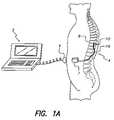
- FIG. 1Ashows a cut-away, vertical view of a patient with a spinal cord stimulator implanted
- FIG. 1Billustrates various configurations of electrode arrays that may be used with a multi-channel stimulator
- FIG. 2shows a fragmentary circuit diagram of a presently practiced circuit in which N digital-to-analog converters (DACs) are uniquely linked to one of N stimulation outputs;
- DACsdigital-to-analog converters
- FIG. 3shows a fragmentary circuit diagram, in accordance with the present invention, in which N ⁇ M total number of switches are used to connect N number of DACs to M stimulation outputs (electrode contacts);
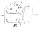
- FIG. 4Ashows a fragmentary circuit diagram, in accordance with the present invention, in which M total number of switches are used to connect N number of DACs to M stimulation outputs (electrode contacts);
- FIG. 4Bshows a specific example of the embodiment of the switching matrix as depicted in FIG. 4A , wherein there are three DACs, twelve outputs (electrode contacts), and twelve switches.
- FIG. 1Ashows a side, cut-away view of a patient 4 and a generalized, implantable, spinal cord stimulation system.
- the implantable systemincludes an IPG 7 and lead 116 connected to an electrode array 110 .
- the IPG 7contains electrical circuitry powered by an internal battery, which circuitry can output current pulses to each stimulation channel and through electrode contacts comprising the electrode array.
- Each stimulation channelcan be connected to at least one electrode contact on the electrode array.
- the electrode contactprovides current to the tissue to be stimulated. Communication with the IPG can be accomplished with an external programmer 5 , using a programmer head 6 .
- FIG. 1Bshows various embodiment of electrode arrays 110 .
- Embodiments (A) through (C)show electrode arrays having in-line electrodes 114 placed on the lead 116 .
- Embodiments (D), (E), (F) and (G)show various paddle-type electrode arrays on a paddle-shaped substrate 119 , 119 a , and 119 b .
- the electrodes 115 , 115 ′can be positioned in parallel columns, as depicted in illustrations (D) and (E), or on separate paddles as in (F), or in-line as in (G).
- FIG. 2shows a fragmentary circuit diagram of a presently practiced circuit in which N number of digital-to-analog converters (DACs) 10 are uniquely linked to one of N stimulation outputs (electrode contacts) 30 .
- a switch 20is used to activate and deactivate a connection between the DAC and stimulation output.
- the switching system showncan be practically used for multi-channel stimulators which have a small number of outputs (electrode contacts). For example, most commercially available spinal cord stimulators do not exceed four channels and so this conventional output connection scheme is workable. Some spinal cord stimulators may employ eight channels and thus a lead or leads having a total of sixteen electrode contacts can be used. For a sixteen channel, monopolar stimulation system, sixteen DACs would need to be used with the conventional output method.
- Bipolar stimulation systemscan also be configured using P-DAC and N-DAC circuits as taught, e.g., in U.S. Pat. No. 6,181,969.
- the trend in the field of implantable medical devicesis to increase the total number of stimulation channels in order to gain increased stimulation flexibility.
- DACsoccupy a high percentage of the space used by the analog circuitry in multi-channel stimulators, it can be appreciated that increasing the number of stimulation channels will undesirably increase the number of DACs and, disadvantageously, require the use of additional space in the medical device.
- Such use of spaceis critical in an implantable device since it is desirable to keep the device size down while increasing the storage capacity of the battery used to power the device and increasing the processing capability of the device.
- the device sizemay be reduced or, alternatively, the size of the battery may be increased.
- the present inventionas described below, enables more stimulation channels (and electrode contacts) to be added while reducing the use of spacing consuming DACs.
- FIG. 3shows a fragmentary circuit diagram, in accordance with the present invention, in which N number of DACs 11 can be connected to M stimulation outputs (electrode contacts) 31 using N ⁇ M total number of switches 21 .
- the N ⁇ M switches 21may be part of an integrated switching module 25 . It can be seen that each DAC 11 is coupled uniquely to a node 26 which, in turn, is connected to a group 50 of M number of switches 21 .
- Each switch 21can further be connected to each one of the M number of single outputs (an electrode contact) 31 . While each switch 21 can only be coupled to one electrode contact 31 by closing the switch 21 , each electrode contact 31 , however, may potentially be switched to N number of possible switches 21 .
- the switches 21may be transistors configured as switches and may include PMOS or MOS transistors.
- the switches 21may be controlled and programmed by a software program or through hardware implementation to prevent connection of two sources of current, i.e., two NDACs 11 , to a single electrode contact 31 .
- Nthe number of DACs employed is less than M, the total number of outputs or electrode contacts 31 . This represents a reduction in the number of total DACs as compared to the conventional design of FIG. 2 , where the number of DACs equals the number of outputs (electrode contacts).
- the electrode contactsmay be selectively switched using the method of the present invention, the method comprising: (a) providing N number of DACs ( 11 ); (b) providing M number of electrode contacts ( 31 ); (c) coupling each of N DACs ( 11 ) to a group of M switches ( 31 ); (d) coupling each of the M switches ( 31 ) uniquely to each of M electrode contacts ( 31 ); and (e) connecting selected switches ( 21 ) by closing the switches, to electrically connect selected electrode contacts ( 31 ) to transmit current, while avoiding closing more than one switch ( 21 ) connected to the same electrode contact ( 31 ) at any one time.
- Each of the N number of DACsmay provide a current that is a different or same amplitude. Not all the DACs need to be operating at the same time. It is also possible that the DACs are all operating at the same time, but the switches, which may be programmed, can be closed to permit current to flow through only selected electrode contacts 31 . It is important that current does not flow from more than a single source, e.g., a DAC, to an electrode contact 31 at any one time.
- FIG. 4Ashows a fragmentary circuit diagram, in accordance with another embodiment of the present invention.
- the system shown in FIG. 4Atakes advantage of the fact that, in many multi-channel stimulators, not all stimulation channels are active (turned on) at any given moment. Only one group of electrodes 100 may be active (the “active electrode group”) at any one time duration, T d .
- Each active electrode groupis labeled # 1 through #L in FIG. 4A .
- Lalso signifies the number of switches 121 in one set or group 110 of switches 121 , connected to one DAC 12 .
- Each active electrode group 100includes N number of outputs (electrode contacts) 130 . In addition N signifies the number of available DACs 12 .
- Mnumber of electrodes
- Ntotal number of switches
- Lnumber of switches in one set of switches
- Lnumber of active electrode groups
- Nnumber of electrodes in one active electrode group
- the switching matrix in FIG. 4Ais configured so that one DAC 12 is uniquely coupled to one grouped set 110 of L number of switches 121 .
- Each DAC 12is connected to a node 126 which, in turn, is connected to one grouped set of 110 of L number of switches 121 .
- Each switch 121uniquely connects to only one electrode contact 130 .
- each active group 110numbered 1 through L draws only one connection from each set 110 of grouped switches. For instance, in the first set of switches 110 , first switch 121 connects to one electrode in active electrode group # 1 , the second switch 121 ′ connects to one electrode in active electrode group # 2 and so on, until the last switch 121 ′′ is connected to one electrode in active electrode group #L.
- the M number of total switches 121may be part of an integrated switching module 25 .
- the outputsmay be switched in a multi-channel stimulator, in accordance with the following method which comprises: (a) providing N number of DACs ( 12 ); (b) providing M number of electrode contacts ( 130 ) and M number of switches ( 110 ); (c) coupling each of N DACs ( 12 ) to at least one set ( 110 ) of switches having L number of switches ( 121 ) in the at least one set ( 110 ); (d) coupling each switch ( 121 ) within the at least one set ( 110 ) of switches, uniquely to one of the M electrode contacts ( 130 ); and (e) causing current to flow through selected electrode contacts ( 130 ) at any one time duration, T d , by closing the associated switches ( 121 ).
- Each of the N number of DACsmay provide a current that is a different or the same amplitude. Not all the DACs need to be operating at the same time. It is also possible that the DACs are all operating but the switches, which may be programmed, can be closed to permit current to flow through only selected electrode contacts 130 .
- FIG. 4Bshows a specific example of the generalized system shown in FIG. 4A .
- Nnumber of DACs
- This simple exampleillustrates that the electrode contacts in groups # 1 through #L may be activated one group at a time, or alternatively, it may be possible to activate all the electrode contacts by closing all of the switches 121 , although the current derived from a single DAC 12 would be divided up into many electrode contacts.
- groups of electrode contactsare activated in a time multiplexed manner, e.g., Group # 1 is activated (with all other Groups not activated), then Group # 2 is activated (with all other Groups not activated), then Group # 3 is activated (with all other groups not activated), and so on.
- the present inventionenables the use of fewer DACs and thereby saves precious device space by employing a switching matrix method and system.
- the switching matrix method and system of the present inventioncan further reduce the number of DACs needed in an implantable, multi-channel stimulator.
Landscapes
- Health & Medical Sciences (AREA)
- Radiology & Medical Imaging (AREA)
- Neurology (AREA)
- Engineering & Computer Science (AREA)
- Biomedical Technology (AREA)
- Nuclear Medicine, Radiotherapy & Molecular Imaging (AREA)
- Life Sciences & Earth Sciences (AREA)
- Animal Behavior & Ethology (AREA)
- General Health & Medical Sciences (AREA)
- Public Health (AREA)
- Veterinary Medicine (AREA)
- Heart & Thoracic Surgery (AREA)
- Neurosurgery (AREA)
- Electrotherapy Devices (AREA)
Abstract
Description
Claims (19)
Priority Applications (1)
| Application Number | Priority Date | Filing Date | Title |
|---|---|---|---|
| US10/686,219US7127298B1 (en) | 2002-10-18 | 2003-10-15 | Switched-matrix output for multi-channel implantable stimulator |
Applications Claiming Priority (2)
| Application Number | Priority Date | Filing Date | Title |
|---|---|---|---|
| US41968402P | 2002-10-18 | 2002-10-18 | |
| US10/686,219US7127298B1 (en) | 2002-10-18 | 2003-10-15 | Switched-matrix output for multi-channel implantable stimulator |
Publications (1)
| Publication Number | Publication Date |
|---|---|
| US7127298B1true US7127298B1 (en) | 2006-10-24 |
Family
ID=37110654
Family Applications (1)
| Application Number | Title | Priority Date | Filing Date |
|---|---|---|---|
| US10/686,219Expired - LifetimeUS7127298B1 (en) | 2002-10-18 | 2003-10-15 | Switched-matrix output for multi-channel implantable stimulator |
Country Status (1)
| Country | Link |
|---|---|
| US (1) | US7127298B1 (en) |
Cited By (71)
| Publication number | Priority date | Publication date | Assignee | Title |
|---|---|---|---|---|
| EP1872826A3 (en)* | 2006-06-30 | 2008-03-12 | Renato Cappelletti | Electrostimulator |
| US20090018619A1 (en)* | 2007-04-30 | 2009-01-15 | Medtronic, Inc. | Shifting of electrical stimulation electrode combinations among differently sized electrode arrays |
| WO2009007883A1 (en)* | 2007-07-10 | 2009-01-15 | Koninklijke Philips Electronics N.V. | Neurostimulation system |
| US20090018617A1 (en)* | 2007-04-30 | 2009-01-15 | Medtronic, Inc. | Parameter-directed shifting of electrical stimulation electrode combinations |
| US20100042187A1 (en)* | 2008-08-14 | 2010-02-18 | Medtronic, Inc. | Connecting electrical sources to electrode nodes in a medical device |
| US20120095529A1 (en)* | 2010-10-13 | 2012-04-19 | Boston Scientific Neuromodulation Corporation | Architectures for an Implantable Medical Device System Having Daisy-Chained Electrode-Driver Integrated Circuits |
| US8805519B2 (en) | 2010-09-30 | 2014-08-12 | Nevro Corporation | Systems and methods for detecting intrathecal penetration |
| US9037249B2 (en) | 2005-07-08 | 2015-05-19 | Boston Scientific Neuromodulation Corporation | Current generation architecture for an implantable stimulator device having coarse and fine current control |
| US9042991B2 (en) | 2013-08-14 | 2015-05-26 | Syntilla Medical LLC | Implantable head mounted neurostimulation system for head pain |
| US9044614B2 (en) | 2013-03-15 | 2015-06-02 | Alfred E. Mann Foundation For Scientific Research | High voltage monitoring successive approximation analog to digital converter |
| US9101768B2 (en) | 2013-03-15 | 2015-08-11 | Globus Medical, Inc. | Spinal cord stimulator system |
| US9155901B2 (en) | 2013-07-29 | 2015-10-13 | Alfred E. Mann Foundation For Scientific Research | Implant charging field control through radio link |
| US9166441B2 (en) | 2013-07-29 | 2015-10-20 | Alfred E. Mann Foundation For Scientific Research | Microprocessor controlled class E driver |
| US9205273B2 (en) | 2013-07-29 | 2015-12-08 | Alfred E. Mann Foundation For Scientific Research | High efficiency magnetic link for implantable devices |
| US9221119B2 (en) | 2013-05-03 | 2015-12-29 | Alfred E. Mann Foundation For Scientific Research | High reliability wire welding for implantable devices |
| US9308378B2 (en) | 2013-05-03 | 2016-04-12 | Alfred E. Mann Foundation For Scientific Research | Implant recharger handshaking system and method |
| US9308373B2 (en) | 2011-06-29 | 2016-04-12 | Boston Scientific Neuromodulation Corporation | Architectures for sharing of current sources in an implantable medical device |
| US9314617B2 (en) | 2005-07-08 | 2016-04-19 | Boston Scientific Neuromodulation Corporation | Current output architecture for an implantable stimulator device |
| US9427574B2 (en) | 2014-08-15 | 2016-08-30 | Axonics Modulation Technologies, Inc. | Implantable lead affixation structure for nerve stimulation to alleviate bladder dysfunction and other indication |
| US9427566B2 (en) | 2013-08-14 | 2016-08-30 | Syntilla Medical LLC | Implantable neurostimulation lead for head pain |
| US9433779B2 (en) | 2013-05-03 | 2016-09-06 | Alfred E. Mann Foundation For Scientific Research | Multi-branch stimulation electrode for subcutaneous field stimulation |
| US9446241B2 (en) | 2013-03-15 | 2016-09-20 | Alfred E. Mann Foundation For Scientific Research | Current sensing multiple output current stimulators |
| US9468770B2 (en) | 2012-07-13 | 2016-10-18 | Advanced Bionics Ag | Random-access electrode addressing systems and methods |
| US9498635B2 (en) | 2013-10-16 | 2016-11-22 | Syntilla Medical LLC | Implantable head located radiofrequency coupled neurostimulation system for head pain |
| US9517338B1 (en) | 2016-01-19 | 2016-12-13 | Axonics Modulation Technologies, Inc. | Multichannel clip device and methods of use |
| US9533155B2 (en) | 2014-08-15 | 2017-01-03 | Axonics Modulation Technologies, Inc. | Methods for determining neurostimulation electrode configurations based on neural localization |
| US9555246B2 (en) | 2014-08-15 | 2017-01-31 | Axonics Modulation Technologies, Inc. | Electromyographic lead positioning and stimulation titration in a nerve stimulation system for treatment of overactive bladder |
| CN106569603A (en)* | 2016-09-08 | 2017-04-19 | 友达光电股份有限公司 | biological stimulation device and method |
| US9700731B2 (en) | 2014-08-15 | 2017-07-11 | Axonics Modulation Technologies, Inc. | Antenna and methods of use for an implantable nerve stimulator |
| US9707406B1 (en) | 2016-01-06 | 2017-07-18 | Syntilla Medical LLC | Charging system incorporating receive coil de-tuning within an implanted device |
| US9728981B2 (en) | 2012-08-31 | 2017-08-08 | Alfred E. Mann Foundation For Scientific Research | Feedback controlled coil driver for inductive power transfer |
| US9802051B2 (en) | 2014-08-15 | 2017-10-31 | Axonics Modulation Technologies, Inc. | External pulse generator device and associated methods for trial nerve stimulation |
| US9839777B2 (en) | 2013-08-14 | 2017-12-12 | Syntilla Medical LLC | Implantable neurostimulation lead for head pain |
| US9872997B2 (en) | 2013-03-15 | 2018-01-23 | Globus Medical, Inc. | Spinal cord stimulator system |
| US9878170B2 (en) | 2013-03-15 | 2018-01-30 | Globus Medical, Inc. | Spinal cord stimulator system |
| US9887574B2 (en) | 2013-03-15 | 2018-02-06 | Globus Medical, Inc. | Spinal cord stimulator system |
| US9895546B2 (en) | 2015-01-09 | 2018-02-20 | Axonics Modulation Technologies, Inc. | Patient remote and associated methods of use with a nerve stimulation system |
| US9925381B2 (en) | 2015-07-10 | 2018-03-27 | Axonics Modulation Technologies, Inc. | Implantable nerve stimulator having internal electronics without ASIC and methods of use |
| US9987493B2 (en) | 2008-10-28 | 2018-06-05 | Medtronic, Inc. | Medical devices and methods for delivery of current-based electrical stimulation therapy |
| US10092762B2 (en) | 2014-08-15 | 2018-10-09 | Axonics Modulation Technologies, Inc. | Integrated electromyographic clinician programmer for use with an implantable neurostimulator |
| US10195423B2 (en) | 2016-01-19 | 2019-02-05 | Axonics Modulation Technologies, Inc. | Multichannel clip device and methods of use |
| US10258805B2 (en) | 2013-10-23 | 2019-04-16 | Syntilla Medical, Llc | Surgical method for implantable head mounted neurostimulation system for head pain |
| US10376704B2 (en) | 2016-02-12 | 2019-08-13 | Axonics Modulation Technologies, Inc. | External pulse generator device and associated methods for trial nerve stimulation |
| US10525253B2 (en) | 2016-10-13 | 2020-01-07 | Boston Scientific Neuromodulation Corporation | Current generation architecture for an implantable medical device including controllable slew rate |
| US10525252B2 (en) | 2016-09-10 | 2020-01-07 | Boston Scientific Neuromodulation Corporation | Compliance voltage monitoring and adjustment in an implantable medical device |
| US10549091B2 (en) | 2016-09-10 | 2020-02-04 | Boston Scientific Neuromodulation Corporation | Use models for a current generation architecture for an implantable medical device |
| US10561835B2 (en) | 2006-10-31 | 2020-02-18 | Medtronic, Inc. | Implantable medical lead with threaded fixation |
| US10576265B2 (en) | 2016-09-10 | 2020-03-03 | Boston Scientific Neuromodulation Corporation | Pulse definition circuitry for creating stimulation waveforms in an implantable pulse generator |
| US10589090B2 (en) | 2016-09-10 | 2020-03-17 | Boston Scientific Neuromodulation Corporation | Implantable stimulator device with magnetic field sensing circuit |
| US10603500B2 (en) | 2016-01-29 | 2020-03-31 | Axonics Modulation Technologies, Inc. | Methods and systems for frequency adjustment to optimize charging of implantable neurostimulator |
| US10632300B2 (en) | 2016-09-10 | 2020-04-28 | Boston Scientific Neuromodulation Corporation | Measurement circuitry for measuring analog values in an implantable pulse generator |
| US10682521B2 (en) | 2014-08-15 | 2020-06-16 | Axonics Modulation Technologies, Inc. | Attachment devices and associated methods of use with a nerve stimulation charging device |
| US10716937B2 (en) | 2016-09-10 | 2020-07-21 | Boston Scientific Neuromodulation Corporation | Passive charge recovery circuitry for an implantable medical device |
| US10716932B2 (en) | 2016-09-10 | 2020-07-21 | Boston Scientific Neuromodulation Corporation | Pulse definition circuitry for creating stimulation waveforms in an implantable pulse generator |
| US10780285B2 (en) | 2017-09-15 | 2020-09-22 | Boston Scientific Neuromodulation Corporation | Current generation architecture for an implantable stimulator device including distributor circuitry for sending an amplitude-scaled current to digital-to-analog converters at the electrodes |
| US10786665B2 (en) | 2016-09-10 | 2020-09-29 | Boston Scientific Neuromodulation Corporation | Biasing of a current generation architecture for an implantable medical device |
| US10792491B2 (en) | 2016-11-23 | 2020-10-06 | Boston Scientific Neuromodulation Corporation | Pulsed passive charge recovery circuitry for an implantable medical device |
| US10912942B2 (en) | 2017-09-15 | 2021-02-09 | Boston Scientific Neuromoduiation Corporation | Current generation architecture for an implantable stimulator device to promote current steering between electrodes |
| US10960215B2 (en) | 2013-10-23 | 2021-03-30 | Nuxcel, Inc. | Low profile head-located neurostimulator and method of fabrication |
| US10980999B2 (en) | 2017-03-09 | 2021-04-20 | Nevro Corp. | Paddle leads and delivery tools, and associated systems and methods |
| US11040192B2 (en) | 2016-09-10 | 2021-06-22 | Boston Scientific Neuromodulation Corporation | Current generation architecture for an implantable medical device |
| US11097111B1 (en) | 2014-05-29 | 2021-08-24 | Stimwave Technologies Incorporated | Stimulation with electrode arrays |
| US11110283B2 (en) | 2018-02-22 | 2021-09-07 | Axonics, Inc. | Neurostimulation leads for trial nerve stimulation and methods of use |
| US11420045B2 (en) | 2018-03-29 | 2022-08-23 | Nevro Corp. | Leads having sidewall openings, and associated systems and methods |
| US11439829B2 (en) | 2019-05-24 | 2022-09-13 | Axonics, Inc. | Clinician programmer methods and systems for maintaining target operating temperatures |
| US11484723B2 (en) | 2015-01-09 | 2022-11-01 | Axonics, Inc. | Attachment devices and associated methods of use with a nerve stimulation charging device |
| US11642537B2 (en) | 2019-03-11 | 2023-05-09 | Axonics, Inc. | Charging device with off-center coil |
| US11848090B2 (en) | 2019-05-24 | 2023-12-19 | Axonics, Inc. | Trainer for a neurostimulator programmer and associated methods of use with a neurostimulation system |
| US11967969B2 (en) | 2021-04-06 | 2024-04-23 | Boston Scientific Neuromodulation Corporation | Current generation architecture for an implantable stimulator device |
| US12383745B2 (en) | 2019-09-06 | 2025-08-12 | Boston Scientific Neuromodulation Corporation | Management of compliance voltage for a stimulator device |
| US12420103B1 (en) | 2020-08-20 | 2025-09-23 | Axonics, Inc. | Neurostimulation leads with reduced current leakage |
Citations (17)
| Publication number | Priority date | Publication date | Assignee | Title |
|---|---|---|---|---|
| US3646940A (en) | 1969-07-15 | 1972-03-07 | Univ Minnesota | Implantable electronic stimulator electrode and method |
| US3724467A (en) | 1971-04-23 | 1973-04-03 | Avery Labor Inc | Electrode implant for the neuro-stimulation of the spinal cord |
| US3822708A (en) | 1972-12-07 | 1974-07-09 | Clinical Technology Corp | Electrical spinal cord stimulating device and method for management of pain |
| US4254776A (en)* | 1976-12-28 | 1981-03-10 | Agency Of Industrial Science & Technology | Apparatus for transmission of information by electrocutaneous stimuli |
| US4532930A (en) | 1983-04-11 | 1985-08-06 | Commonwealth Of Australia, Dept. Of Science & Technology | Cochlear implant system for an auditory prosthesis |
| US4592359A (en) | 1985-04-02 | 1986-06-03 | The Board Of Trustees Of The Leland Stanford Junior University | Multi-channel implantable neural stimulator |
| US4726379A (en)* | 1985-11-14 | 1988-02-23 | Cardiac Control Systems, Inc. | Cardiac pacer with switching circuit for isolation |
| US4947844A (en) | 1984-09-07 | 1990-08-14 | The University Of Melbourne | Receiver/stimulator for hearing prosthesis |
| US5776172A (en) | 1989-09-22 | 1998-07-07 | Alfred E. Mann Foundation For Scientific Research | Multichannel implantable cochlear stimulator |
| US6002966A (en)* | 1995-04-26 | 1999-12-14 | Advanced Bionics Corporation | Multichannel cochlear prosthesis with flexible control of stimulus waveforms |
| US6067474A (en) | 1997-08-01 | 2000-05-23 | Advanced Bionics Corporation | Implantable device with improved battery recharging and powering configuration |
| US6181969B1 (en) | 1998-06-26 | 2001-01-30 | Advanced Bionics Corporation | Programmable current output stimulus stage for implantable device |
| WO2002009808A1 (en) | 2000-07-26 | 2002-02-07 | Advanced Bionics Corporation | Rechargeable spinal cord stimulator system |
| US6381496B1 (en) | 1999-10-01 | 2002-04-30 | Advanced Bionics Corporation | Parameter context switching for an implanted device |
| US6516227B1 (en) | 1999-07-27 | 2003-02-04 | Advanced Bionics Corporation | Rechargeable spinal cord stimulator system |
| US20030114899A1 (en) | 1999-07-27 | 2003-06-19 | Woods Carla Mann | Patient programmer for implantable devices |
| US6622048B1 (en) | 1999-12-06 | 2003-09-16 | Advanced Bionics Corporation | Implantable device programmer |
- 2003
- 2003-10-15USUS10/686,219patent/US7127298B1/ennot_activeExpired - Lifetime
Patent Citations (18)
| Publication number | Priority date | Publication date | Assignee | Title |
|---|---|---|---|---|
| US3646940A (en) | 1969-07-15 | 1972-03-07 | Univ Minnesota | Implantable electronic stimulator electrode and method |
| US3724467A (en) | 1971-04-23 | 1973-04-03 | Avery Labor Inc | Electrode implant for the neuro-stimulation of the spinal cord |
| US3822708A (en) | 1972-12-07 | 1974-07-09 | Clinical Technology Corp | Electrical spinal cord stimulating device and method for management of pain |
| US4254776A (en)* | 1976-12-28 | 1981-03-10 | Agency Of Industrial Science & Technology | Apparatus for transmission of information by electrocutaneous stimuli |
| US4532930A (en) | 1983-04-11 | 1985-08-06 | Commonwealth Of Australia, Dept. Of Science & Technology | Cochlear implant system for an auditory prosthesis |
| US4947844A (en) | 1984-09-07 | 1990-08-14 | The University Of Melbourne | Receiver/stimulator for hearing prosthesis |
| US4592359A (en) | 1985-04-02 | 1986-06-03 | The Board Of Trustees Of The Leland Stanford Junior University | Multi-channel implantable neural stimulator |
| US4726379A (en)* | 1985-11-14 | 1988-02-23 | Cardiac Control Systems, Inc. | Cardiac pacer with switching circuit for isolation |
| US5776172A (en) | 1989-09-22 | 1998-07-07 | Alfred E. Mann Foundation For Scientific Research | Multichannel implantable cochlear stimulator |
| US6002966A (en)* | 1995-04-26 | 1999-12-14 | Advanced Bionics Corporation | Multichannel cochlear prosthesis with flexible control of stimulus waveforms |
| US6067474A (en) | 1997-08-01 | 2000-05-23 | Advanced Bionics Corporation | Implantable device with improved battery recharging and powering configuration |
| US6181969B1 (en) | 1998-06-26 | 2001-01-30 | Advanced Bionics Corporation | Programmable current output stimulus stage for implantable device |
| US6516227B1 (en) | 1999-07-27 | 2003-02-04 | Advanced Bionics Corporation | Rechargeable spinal cord stimulator system |
| US20030114899A1 (en) | 1999-07-27 | 2003-06-19 | Woods Carla Mann | Patient programmer for implantable devices |
| US20030120323A1 (en) | 1999-07-27 | 2003-06-26 | Meadows Paul M. | Rechargeable spinal cord stimulator system |
| US6381496B1 (en) | 1999-10-01 | 2002-04-30 | Advanced Bionics Corporation | Parameter context switching for an implanted device |
| US6622048B1 (en) | 1999-12-06 | 2003-09-16 | Advanced Bionics Corporation | Implantable device programmer |
| WO2002009808A1 (en) | 2000-07-26 | 2002-02-07 | Advanced Bionics Corporation | Rechargeable spinal cord stimulator system |
Cited By (180)
| Publication number | Priority date | Publication date | Assignee | Title |
|---|---|---|---|---|
| US11452873B2 (en) | 2005-07-08 | 2022-09-27 | Boston Scientific Neuromodulation Corporation | Current generation architecture for an implantable stimulator device having coarse and fine current control |
| US9314617B2 (en) | 2005-07-08 | 2016-04-19 | Boston Scientific Neuromodulation Corporation | Current output architecture for an implantable stimulator device |
| US9308371B2 (en) | 2005-07-08 | 2016-04-12 | Boston Scientific Neuromodulation Corporation | Current generation architecture for an implantable stimulator device having coarse and fine current control |
| US10744318B2 (en) | 2005-07-08 | 2020-08-18 | Boston Scientific Neuromodulation Corporation | Current output architecture for an implantable stimulator device |
| US10744325B2 (en) | 2005-07-08 | 2020-08-18 | Boston Scientific Neuromodulation Corporation | Current generation architecture for an implantable stimulator device having coarse and fine current control |
| US9931502B2 (en) | 2005-07-08 | 2018-04-03 | Boston Scientific Neuromodulation Corporation | Current output architecture for an implantable stimulator device |
| US9956411B2 (en) | 2005-07-08 | 2018-05-01 | Boston Scientific Neuromodulation Corporation | Current generation architecture for an implantable stimulator device having coarse and fine current control |
| US9037249B2 (en) | 2005-07-08 | 2015-05-19 | Boston Scientific Neuromodulation Corporation | Current generation architecture for an implantable stimulator device having coarse and fine current control |
| EP1872826A3 (en)* | 2006-06-30 | 2008-03-12 | Renato Cappelletti | Electrostimulator |
| US10561835B2 (en) | 2006-10-31 | 2020-02-18 | Medtronic, Inc. | Implantable medical lead with threaded fixation |
| US20090018619A1 (en)* | 2007-04-30 | 2009-01-15 | Medtronic, Inc. | Shifting of electrical stimulation electrode combinations among differently sized electrode arrays |
| US20090018617A1 (en)* | 2007-04-30 | 2009-01-15 | Medtronic, Inc. | Parameter-directed shifting of electrical stimulation electrode combinations |
| US9937342B2 (en)* | 2007-04-30 | 2018-04-10 | Medtronic, Inc. | Shifting of electrical stimulation electrode combinations among differently sized electrode arrays |
| US20100198315A1 (en)* | 2007-07-10 | 2010-08-05 | Koninklijke Philips Electronics N.V. | Neurostimulation system |
| CN101687097A (en)* | 2007-07-10 | 2010-03-31 | 皇家飞利浦电子股份有限公司 | Neurostimulation system |
| WO2009007883A1 (en)* | 2007-07-10 | 2009-01-15 | Koninklijke Philips Electronics N.V. | Neurostimulation system |
| CN101687097B (en)* | 2007-07-10 | 2014-02-26 | 沙皮恩斯脑部刺激控制有限公司 | neurostimulation system |
| US8694105B2 (en) | 2007-07-10 | 2014-04-08 | Sapiens Steering Brain Stimulation B.V. | Neurostimulation system having a controller for controlling the supply of electrical pulses |
| US8655453B2 (en) | 2008-08-14 | 2014-02-18 | Medtronic, Inc. | Connecting electrical sources to electrode nodes in a medical device |
| US20100042187A1 (en)* | 2008-08-14 | 2010-02-18 | Medtronic, Inc. | Connecting electrical sources to electrode nodes in a medical device |
| US9987493B2 (en) | 2008-10-28 | 2018-06-05 | Medtronic, Inc. | Medical devices and methods for delivery of current-based electrical stimulation therapy |
| US8805519B2 (en) | 2010-09-30 | 2014-08-12 | Nevro Corporation | Systems and methods for detecting intrathecal penetration |
| US10279183B2 (en) | 2010-09-30 | 2019-05-07 | Nevro Corp. | Systems and methods for detecting intrathecal penetration |
| US9358388B2 (en) | 2010-09-30 | 2016-06-07 | Nevro Corporation | Systems and methods for detecting intrathecal penetration |
| US20120095529A1 (en)* | 2010-10-13 | 2012-04-19 | Boston Scientific Neuromodulation Corporation | Architectures for an Implantable Medical Device System Having Daisy-Chained Electrode-Driver Integrated Circuits |
| US9795793B2 (en)* | 2010-10-13 | 2017-10-24 | Boston Scientific Neuromodulation Corporation | Architectures for an implantable medical device system having daisy-chained electrode-driver integrated circuits |
| AU2011313977B2 (en)* | 2010-10-13 | 2015-07-02 | Boston Scientific Neuromodulation Corporation | Architectures for an implantable medical device system having daisy-chained electrode-drive integrated circuits |
| EP3939651B1 (en)* | 2011-06-29 | 2025-08-20 | Boston Scientific Neuromodulation Corporation | Architectures for sharing of current sources in an implantable medical device |
| US9308373B2 (en) | 2011-06-29 | 2016-04-12 | Boston Scientific Neuromodulation Corporation | Architectures for sharing of current sources in an implantable medical device |
| US11697022B2 (en) | 2011-06-29 | 2023-07-11 | Boston Scientific Neuromodulation Corporation | Architectures for sharing of current sources in an implantable medical device |
| US10092757B2 (en) | 2011-06-29 | 2018-10-09 | Boston Scientific Neuromodulation Corporation | Architectures for sharing of current sources in an implantable medical device |
| US10918868B2 (en) | 2011-06-29 | 2021-02-16 | Boston Scientific Neuromodulation Corporation | Architectures for sharing of current sources in an implantable medical device |
| US9468770B2 (en) | 2012-07-13 | 2016-10-18 | Advanced Bionics Ag | Random-access electrode addressing systems and methods |
| US9728981B2 (en) | 2012-08-31 | 2017-08-08 | Alfred E. Mann Foundation For Scientific Research | Feedback controlled coil driver for inductive power transfer |
| US9623246B2 (en) | 2013-03-15 | 2017-04-18 | Globus Medical, Inc. | Spinal cord stimulator system |
| US9682237B2 (en) | 2013-03-15 | 2017-06-20 | Alfred E. Mann Foundation For Scientific Research | High voltage monitoring successive approximation analog to digital converter |
| US10335597B2 (en) | 2013-03-15 | 2019-07-02 | Cirtec Medical Corp. | Spinal cord stimulator system |
| US9492665B2 (en) | 2013-03-15 | 2016-11-15 | Globus Medical, Inc. | Spinal cord stimulator system |
| US10265526B2 (en) | 2013-03-15 | 2019-04-23 | Cirtec Medical Corp. | Spinal cord stimulator system |
| US9550062B2 (en) | 2013-03-15 | 2017-01-24 | Globus Medical, Inc | Spinal cord stimulator system |
| US10149977B2 (en) | 2013-03-15 | 2018-12-11 | Cirtec Medical Corp. | Spinal cord stimulator system |
| US9446241B2 (en) | 2013-03-15 | 2016-09-20 | Alfred E. Mann Foundation For Scientific Research | Current sensing multiple output current stimulators |
| US10810614B2 (en) | 2013-03-15 | 2020-10-20 | Cirtec Medical Corp. | Spinal cord stimulator system |
| US10016605B2 (en) | 2013-03-15 | 2018-07-10 | Globus Medical, Inc. | Spinal cord stimulator system |
| US11338144B2 (en) | 2013-03-15 | 2022-05-24 | Alfred E. Mann Foundation For Scientific Research | Current sensing multiple output current stimulators |
| US10603495B2 (en) | 2013-03-15 | 2020-03-31 | The Alfred E. Mann Foundation For Scientific Research | Current sensing multiple output current stimulators |
| US10016602B2 (en) | 2013-03-15 | 2018-07-10 | Globus Medical, Inc. | Spinal cord stimulator system |
| US9440076B2 (en) | 2013-03-15 | 2016-09-13 | Globus Medical, Inc. | Spinal cord stimulator system |
| US9981130B2 (en) | 2013-03-15 | 2018-05-29 | Alfred E. Mann Foundation For Scientific Research | Current sensing multiple output current stimulators |
| US11704688B2 (en) | 2013-03-15 | 2023-07-18 | Cirtec Medical Corp. | Spinal cord stimulator system |
| US9308369B2 (en) | 2013-03-15 | 2016-04-12 | Globus Medical, Inc. | Spinal cord stimulator system |
| US9956409B2 (en) | 2013-03-15 | 2018-05-01 | Globus Medical, Inc. | Spinal cord stimulator system |
| US9101768B2 (en) | 2013-03-15 | 2015-08-11 | Globus Medical, Inc. | Spinal cord stimulator system |
| US9044614B2 (en) | 2013-03-15 | 2015-06-02 | Alfred E. Mann Foundation For Scientific Research | High voltage monitoring successive approximation analog to digital converter |
| US9887574B2 (en) | 2013-03-15 | 2018-02-06 | Globus Medical, Inc. | Spinal cord stimulator system |
| US9872997B2 (en) | 2013-03-15 | 2018-01-23 | Globus Medical, Inc. | Spinal cord stimulator system |
| US9878170B2 (en) | 2013-03-15 | 2018-01-30 | Globus Medical, Inc. | Spinal cord stimulator system |
| US9872986B2 (en) | 2013-03-15 | 2018-01-23 | Globus Medical, Inc. | Spinal cord stimulator system |
| US9675807B2 (en) | 2013-05-03 | 2017-06-13 | Alfred E. Mann Foundation For Scientific Research | High reliability wire welding for implantable devices |
| US9433779B2 (en) | 2013-05-03 | 2016-09-06 | Alfred E. Mann Foundation For Scientific Research | Multi-branch stimulation electrode for subcutaneous field stimulation |
| US9221119B2 (en) | 2013-05-03 | 2015-12-29 | Alfred E. Mann Foundation For Scientific Research | High reliability wire welding for implantable devices |
| US10029090B2 (en) | 2013-05-03 | 2018-07-24 | Alfred E. Mann Foundation For Scientific Research | Multi-branch stimulation electrode for subcutaneous field stimulation |
| US9308378B2 (en) | 2013-05-03 | 2016-04-12 | Alfred E. Mann Foundation For Scientific Research | Implant recharger handshaking system and method |
| US9789325B2 (en) | 2013-05-03 | 2017-10-17 | Alfred E. Mann Foundation For Scientific Research | Implant recharger handshaking system and method |
| US9155901B2 (en) | 2013-07-29 | 2015-10-13 | Alfred E. Mann Foundation For Scientific Research | Implant charging field control through radio link |
| US9780596B2 (en) | 2013-07-29 | 2017-10-03 | Alfred E. Mann Foundation For Scientific Research | Microprocessor controlled class E driver |
| US9855436B2 (en) | 2013-07-29 | 2018-01-02 | Alfred E. Mann Foundation For Scientific Research | High efficiency magnetic link for implantable devices |
| US10447083B2 (en) | 2013-07-29 | 2019-10-15 | The Alfred E. Mann Foundation For Scientific Research | Microprocessor controlled class E driver |
| US10449377B2 (en) | 2013-07-29 | 2019-10-22 | The Alfred E. Mann Foundation For Scientific Research | High efficiency magnetic link for implantable devices |
| US10971950B2 (en) | 2013-07-29 | 2021-04-06 | The Alfred E. Mann Foundation For Scientific Research | Microprocessor controlled class E driver |
| US9166441B2 (en) | 2013-07-29 | 2015-10-20 | Alfred E. Mann Foundation For Scientific Research | Microprocessor controlled class E driver |
| US11722007B2 (en) | 2013-07-29 | 2023-08-08 | The Alfred E. Mann Foundation For Scientific Rsrch | Microprocessor controlled class E driver |
| US9205273B2 (en) | 2013-07-29 | 2015-12-08 | Alfred E. Mann Foundation For Scientific Research | High efficiency magnetic link for implantable devices |
| US9839777B2 (en) | 2013-08-14 | 2017-12-12 | Syntilla Medical LLC | Implantable neurostimulation lead for head pain |
| US9427566B2 (en) | 2013-08-14 | 2016-08-30 | Syntilla Medical LLC | Implantable neurostimulation lead for head pain |
| US9974968B2 (en) | 2013-08-14 | 2018-05-22 | Syntilla Medical LLC | Implantable head mounted neurostimulation system for head pain |
| US9884190B2 (en) | 2013-08-14 | 2018-02-06 | Syntilla Medical LLC | Surgical method for implantable head mounted neurostimulation system for head pain |
| US9042991B2 (en) | 2013-08-14 | 2015-05-26 | Syntilla Medical LLC | Implantable head mounted neurostimulation system for head pain |
| US9498635B2 (en) | 2013-10-16 | 2016-11-22 | Syntilla Medical LLC | Implantable head located radiofrequency coupled neurostimulation system for head pain |
| US9889308B2 (en) | 2013-10-23 | 2018-02-13 | Syntilla Medical LLC | Implantable head located radiofrequency coupled neurostimulation system for head pain |
| US11612756B2 (en) | 2013-10-23 | 2023-03-28 | Shiratronics, Inc. | Implantable head mounted neurostimulation system for head pain |
| US11357995B2 (en) | 2013-10-23 | 2022-06-14 | Shiratronics, Inc. | Implantable head located radiofrequency coupled neurostimulation system for head pain |
| US10960215B2 (en) | 2013-10-23 | 2021-03-30 | Nuxcel, Inc. | Low profile head-located neurostimulator and method of fabrication |
| US10946205B2 (en) | 2013-10-23 | 2021-03-16 | Nuxcel, Inc. | Implantable head mounted neurostimulation system for head pain |
| US11400302B2 (en) | 2013-10-23 | 2022-08-02 | Shiratronics, Inc. | Surgical method for implantable neurostimulation system for pain |
| US10850112B2 (en) | 2013-10-23 | 2020-12-01 | Nuxcel, Inc. | Surgical method for implantable neurostimulation system for pain |
| US12070610B2 (en) | 2013-10-23 | 2024-08-27 | Shiratronics, Inc. | Low profile head-located neurostimulator |
| US10258805B2 (en) | 2013-10-23 | 2019-04-16 | Syntilla Medical, Llc | Surgical method for implantable head mounted neurostimulation system for head pain |
| US9539432B2 (en) | 2013-10-23 | 2017-01-10 | Syntilla Medical LLC | Implantable head located radiofrequency coupled neurostimulation system for head pain |
| US11623100B2 (en) | 2013-10-23 | 2023-04-11 | Shiratronics, Inc. | Low profile head-located neurostimulator |
| US9498636B2 (en) | 2013-10-23 | 2016-11-22 | Syntilla Medical LLC | Implantable head located radiofrequency coupled neurostimulation system for head pain |
| US10695571B2 (en) | 2013-10-23 | 2020-06-30 | Nuxcel, Inc. | Implantable head located radiofrequency coupled neurostimulation system for head pain |
| US11857796B1 (en) | 2014-05-29 | 2024-01-02 | Curonix Llc | Stimulation with electrode arrays |
| US11097111B1 (en) | 2014-05-29 | 2021-08-24 | Stimwave Technologies Incorporated | Stimulation with electrode arrays |
| US12296178B2 (en) | 2014-05-29 | 2025-05-13 | Curonix Llc | Stimulation with electrode arrays |
| US9427574B2 (en) | 2014-08-15 | 2016-08-30 | Axonics Modulation Technologies, Inc. | Implantable lead affixation structure for nerve stimulation to alleviate bladder dysfunction and other indication |
| US9533155B2 (en) | 2014-08-15 | 2017-01-03 | Axonics Modulation Technologies, Inc. | Methods for determining neurostimulation electrode configurations based on neural localization |
| US11116985B2 (en) | 2014-08-15 | 2021-09-14 | Axonics, Inc. | Clinician programmer for use with an implantable neurostimulation lead |
| US9855423B2 (en) | 2014-08-15 | 2018-01-02 | Axonics Modulation Technologies, Inc. | Systems and methods for neurostimulation electrode configurations based on neural localization |
| US11213675B2 (en) | 2014-08-15 | 2022-01-04 | Axonics, Inc. | Implantable lead affixation structure for nerve stimulation to alleviate bladder dysfunction and other indication |
| US10406369B2 (en) | 2014-08-15 | 2019-09-10 | Axonics Modulation Technologies, Inc. | Electromyographic lead positioning and stimulation titration in a nerve stimulation system for treatment of overactive bladder |
| US11497916B2 (en) | 2014-08-15 | 2022-11-15 | Axonics, Inc. | Electromyographic lead positioning and stimulation titration in a nerve stimulation system for treatment of overactive bladder |
| US10589103B2 (en) | 2014-08-15 | 2020-03-17 | Axonics Modulation Technologies, Inc. | External pulse generator device and associated methods for trial nerve stimulation |
| US9700731B2 (en) | 2014-08-15 | 2017-07-11 | Axonics Modulation Technologies, Inc. | Antenna and methods of use for an implantable nerve stimulator |
| US10092762B2 (en) | 2014-08-15 | 2018-10-09 | Axonics Modulation Technologies, Inc. | Integrated electromyographic clinician programmer for use with an implantable neurostimulator |
| US11389659B2 (en) | 2014-08-15 | 2022-07-19 | Axonics, Inc. | External pulse generator device and associated methods for trial nerve stimulation |
| US9802051B2 (en) | 2014-08-15 | 2017-10-31 | Axonics Modulation Technologies, Inc. | External pulse generator device and associated methods for trial nerve stimulation |
| US10682521B2 (en) | 2014-08-15 | 2020-06-16 | Axonics Modulation Technologies, Inc. | Attachment devices and associated methods of use with a nerve stimulation charging device |
| US9561372B2 (en) | 2014-08-15 | 2017-02-07 | Axonics Modulation Technologies, Inc. | Electromyographic lead positioning and stimulation titration in a nerve stimulation system for treatment of overactive bladder |
| US9555246B2 (en) | 2014-08-15 | 2017-01-31 | Axonics Modulation Technologies, Inc. | Electromyographic lead positioning and stimulation titration in a nerve stimulation system for treatment of overactive bladder |
| US11730411B2 (en) | 2014-08-15 | 2023-08-22 | Axonics, Inc. | Methods for determining neurostimulation electrode configurations based on neural localization |
| US10478619B2 (en) | 2014-08-15 | 2019-11-19 | Axonics Modulation Technologies, Inc. | Implantable lead affixation structure for nerve stimulation to alleviate bladder dysfunction and other indication |
| US10729903B2 (en) | 2014-08-15 | 2020-08-04 | Axonics Modulation Technologies, Inc. | Methods for determining neurostimulation electrode configurations based on neural localization |
| US9802038B2 (en) | 2014-08-15 | 2017-10-31 | Axonics Modulation Technologies, Inc. | Implantable lead affixation structure for nerve stimulation to alleviate bladder dysfunction and other indication |
| US9770596B2 (en) | 2015-01-09 | 2017-09-26 | Axonics Modulation Technologies, Inc. | Antenna and methods of use for an implantable nerve stimulator |
| US10384067B2 (en) | 2015-01-09 | 2019-08-20 | Axonics Modulation Technologies, Inc. | Patient remote and associated methods of use with a nerve stimulation system |
| US10722721B2 (en) | 2015-01-09 | 2020-07-28 | Axonics Modulation Technologies, Inc. | Antenna and methods of use for an implantable nerve stimulator |
| US9895546B2 (en) | 2015-01-09 | 2018-02-20 | Axonics Modulation Technologies, Inc. | Patient remote and associated methods of use with a nerve stimulation system |
| US11478648B2 (en) | 2015-01-09 | 2022-10-25 | Axonics, Inc. | Antenna and methods of use for an implantable nerve stimulator |
| US10105542B2 (en) | 2015-01-09 | 2018-10-23 | Axonics Modulation Technologies, Inc. | Patient remote and associated methods of use with a nerve stimulation system |
| US11123569B2 (en) | 2015-01-09 | 2021-09-21 | Axonics, Inc. | Patient remote and associated methods of use with a nerve stimulation system |
| US11484723B2 (en) | 2015-01-09 | 2022-11-01 | Axonics, Inc. | Attachment devices and associated methods of use with a nerve stimulation charging device |
| US11766568B2 (en) | 2015-07-10 | 2023-09-26 | Axonics, Inc. | Implantable nerve stimulator having internal electronics without ASIC and methods of use |
| US9925381B2 (en) | 2015-07-10 | 2018-03-27 | Axonics Modulation Technologies, Inc. | Implantable nerve stimulator having internal electronics without ASIC and methods of use |
| US10850104B2 (en) | 2015-07-10 | 2020-12-01 | Axonics Modulation Technologies, Inc. | Implantable nerve stimulator having internal electronics without ASIC and methods of use |
| US9707406B1 (en) | 2016-01-06 | 2017-07-18 | Syntilla Medical LLC | Charging system incorporating receive coil de-tuning within an implanted device |
| US10022549B2 (en) | 2016-01-06 | 2018-07-17 | Syntilla Medical LLC | Charging system incorporating data communication and power transmission using opposite polarity half-wave rectified signals received by implanted device |
| US9757575B2 (en) | 2016-01-06 | 2017-09-12 | Syntilla Medical LLC | Charging system including transmit coil current sensing circuitry |
| US9833629B2 (en) | 2016-01-06 | 2017-12-05 | Syntilla Medical LLC | Charging system providing adjustable transmitted power to improve power efficiency within an implanted device |
| US9713726B1 (en) | 2016-01-06 | 2017-07-25 | Syntilla Medical LLC | Charging system incorporating feedback excitation control of resonant coil driver amplifier |
| US9717917B2 (en) | 2016-01-06 | 2017-08-01 | Syntilla Medical LLC | Charging system incorporating independent charging and communication with multiple implanted devices |
| US9839788B2 (en) | 2016-01-06 | 2017-12-12 | Syntilla Medical LLC | Charging system incorporating bi-directional communication with implanted device |
| US10195423B2 (en) | 2016-01-19 | 2019-02-05 | Axonics Modulation Technologies, Inc. | Multichannel clip device and methods of use |
| US9517338B1 (en) | 2016-01-19 | 2016-12-13 | Axonics Modulation Technologies, Inc. | Multichannel clip device and methods of use |
| US11602638B2 (en) | 2016-01-29 | 2023-03-14 | Axonics, Inc. | Methods and systems for frequency adjustment to optimize charging of implantable neurostimulator |
| US11083903B2 (en) | 2016-01-29 | 2021-08-10 | Axonics, Inc. | Methods and systems for frequency adjustment to optimize charging of implantable neurostimulator |
| US10603500B2 (en) | 2016-01-29 | 2020-03-31 | Axonics Modulation Technologies, Inc. | Methods and systems for frequency adjustment to optimize charging of implantable neurostimulator |
| US12083349B2 (en) | 2016-01-29 | 2024-09-10 | Axonics, Inc. | Methods and systems for frequency adjustment to optimize charging of implantable neurostimulator |
| US11260236B2 (en) | 2016-02-12 | 2022-03-01 | Axonics, Inc. | External pulse generator device and affixation device for trial nerve stimulation and methods of use |
| US10376704B2 (en) | 2016-02-12 | 2019-08-13 | Axonics Modulation Technologies, Inc. | External pulse generator device and associated methods for trial nerve stimulation |
| US12226643B2 (en) | 2016-02-12 | 2025-02-18 | Axonics, Inc. | External pulse generator device and affixation device for trial nerve stimulation and methods of use |
| CN106569603A (en)* | 2016-09-08 | 2017-04-19 | 友达光电股份有限公司 | biological stimulation device and method |
| US10786665B2 (en) | 2016-09-10 | 2020-09-29 | Boston Scientific Neuromodulation Corporation | Biasing of a current generation architecture for an implantable medical device |
| US10576265B2 (en) | 2016-09-10 | 2020-03-03 | Boston Scientific Neuromodulation Corporation | Pulse definition circuitry for creating stimulation waveforms in an implantable pulse generator |
| US12370359B2 (en) | 2016-09-10 | 2025-07-29 | Boston Scientific Neuromodulation Corporation | Pulse definition circuitry for creating stimulation waveforms in an implantable pulse generator |
| US11364382B2 (en) | 2016-09-10 | 2022-06-21 | Boston Scientific Neuromodulation Corporation | Passive charge recovery circuitry for an implantable medical device |
| US11273303B2 (en) | 2016-09-10 | 2022-03-15 | Boston Scientific Neuromodulation Corporation | Compliance voltage monitoring and adjustment in an implantable medical device |
| US10525252B2 (en) | 2016-09-10 | 2020-01-07 | Boston Scientific Neuromodulation Corporation | Compliance voltage monitoring and adjustment in an implantable medical device |
| US10549091B2 (en) | 2016-09-10 | 2020-02-04 | Boston Scientific Neuromodulation Corporation | Use models for a current generation architecture for an implantable medical device |
| US11590344B2 (en) | 2016-09-10 | 2023-02-28 | Boston Scientific Neuromodulation Corporation | Current generation architecture for an implantable medical device |
| US12128234B2 (en) | 2016-09-10 | 2024-10-29 | Boston Scientific Neuromodulation Corporation | Passive charge recovery circuitry for an implantable medical device |
| US11040192B2 (en) | 2016-09-10 | 2021-06-22 | Boston Scientific Neuromodulation Corporation | Current generation architecture for an implantable medical device |
| US10589090B2 (en) | 2016-09-10 | 2020-03-17 | Boston Scientific Neuromodulation Corporation | Implantable stimulator device with magnetic field sensing circuit |
| US12023482B2 (en) | 2016-09-10 | 2024-07-02 | Boston Scientific Neuromodulation Corporation | Compliance voltage monitoring and adjustment in an implantable medical device |
| US11998732B2 (en) | 2016-09-10 | 2024-06-04 | Boston Scientific Neuromodulation Corporation | Current generation architecture for an implantable medical device |
| US10632300B2 (en) | 2016-09-10 | 2020-04-28 | Boston Scientific Neuromodulation Corporation | Measurement circuitry for measuring analog values in an implantable pulse generator |
| US11793999B2 (en) | 2016-09-10 | 2023-10-24 | Boston Scientific Neuromodulation Corporation | Pulse definition circuitry for creating stimulation waveforms in an implantable pulse generator |
| US10716937B2 (en) | 2016-09-10 | 2020-07-21 | Boston Scientific Neuromodulation Corporation | Passive charge recovery circuitry for an implantable medical device |
| US10716932B2 (en) | 2016-09-10 | 2020-07-21 | Boston Scientific Neuromodulation Corporation | Pulse definition circuitry for creating stimulation waveforms in an implantable pulse generator |
| US10525253B2 (en) | 2016-10-13 | 2020-01-07 | Boston Scientific Neuromodulation Corporation | Current generation architecture for an implantable medical device including controllable slew rate |
| US11577073B2 (en) | 2016-11-23 | 2023-02-14 | Boston Scientific Neuromodulation Corporation | Pulsed passive charge recovery circuitry for an implantable medical device |
| US12285603B2 (en) | 2016-11-23 | 2025-04-29 | Boston Scientific Neuromodulation Corporation | Pulsed passive charge recovery circuitry for an implantable medical device |
| US10792491B2 (en) | 2016-11-23 | 2020-10-06 | Boston Scientific Neuromodulation Corporation | Pulsed passive charge recovery circuitry for an implantable medical device |
| US10980999B2 (en) | 2017-03-09 | 2021-04-20 | Nevro Corp. | Paddle leads and delivery tools, and associated systems and methods |
| US11759631B2 (en) | 2017-03-09 | 2023-09-19 | Nevro Corp. | Paddle leads and delivery tools, and associated systems and methods |
| US10780285B2 (en) | 2017-09-15 | 2020-09-22 | Boston Scientific Neuromodulation Corporation | Current generation architecture for an implantable stimulator device including distributor circuitry for sending an amplitude-scaled current to digital-to-analog converters at the electrodes |
| US11697021B2 (en) | 2017-09-15 | 2023-07-11 | Boston Scientific Neuromodulation Corporation | Current generation architecture for an implantable stimulator device to promote current steering between electrodes |
| US10912942B2 (en) | 2017-09-15 | 2021-02-09 | Boston Scientific Neuromoduiation Corporation | Current generation architecture for an implantable stimulator device to promote current steering between electrodes |
| US11724114B2 (en) | 2017-09-15 | 2023-08-15 | Boston Scientific Neuromodulation Corporation | Current generation architecture for an implantable stimulator device including distributor circuitry for sending an amplitude-scaled current to digital-to-analog converters at the electrodes |
| US12042662B2 (en) | 2018-02-22 | 2024-07-23 | Axonics, Inc. | Neurostimulation leads for trial nerve stimulation and methods of use |
| US11511122B2 (en) | 2018-02-22 | 2022-11-29 | Axonics, Inc. | Neurostimulation leads for trial nerve stimulation and methods of use |
| US11110283B2 (en) | 2018-02-22 | 2021-09-07 | Axonics, Inc. | Neurostimulation leads for trial nerve stimulation and methods of use |
| US11420045B2 (en) | 2018-03-29 | 2022-08-23 | Nevro Corp. | Leads having sidewall openings, and associated systems and methods |
| US11642537B2 (en) | 2019-03-11 | 2023-05-09 | Axonics, Inc. | Charging device with off-center coil |
| US11848090B2 (en) | 2019-05-24 | 2023-12-19 | Axonics, Inc. | Trainer for a neurostimulator programmer and associated methods of use with a neurostimulation system |
| US11439829B2 (en) | 2019-05-24 | 2022-09-13 | Axonics, Inc. | Clinician programmer methods and systems for maintaining target operating temperatures |
| US12383745B2 (en) | 2019-09-06 | 2025-08-12 | Boston Scientific Neuromodulation Corporation | Management of compliance voltage for a stimulator device |
| US12420103B1 (en) | 2020-08-20 | 2025-09-23 | Axonics, Inc. | Neurostimulation leads with reduced current leakage |
| US12231139B2 (en) | 2021-04-06 | 2025-02-18 | Boston Scientific Neuromodulation Corporation | Current generation architecture for an implantable stimulator device |
| US11967969B2 (en) | 2021-04-06 | 2024-04-23 | Boston Scientific Neuromodulation Corporation | Current generation architecture for an implantable stimulator device |
Similar Documents
| Publication | Publication Date | Title |
|---|---|---|
| US7127298B1 (en) | Switched-matrix output for multi-channel implantable stimulator | |
| US11697022B2 (en) | Architectures for sharing of current sources in an implantable medical device | |
| US10744318B2 (en) | Current output architecture for an implantable stimulator device | |
| US10293166B2 (en) | Fractionalized stimulation pulses in an implantable stimulator device | |
| US8121703B1 (en) | Dual-range compliance voltage supply for a multi-channel stimulator | |
| US7539538B2 (en) | Low power loss current digital-to-analog converter used in an implantable pulse generator | |
| US8706238B2 (en) | Current generation architecture for an implantable stimulator device having coarse and fine current control | |
| US10576264B2 (en) | Selected simultaneous stimulation | |
| WO2018051213A1 (en) | Single-wire electrode array | |
| CN119303231A (en) | A multi-channel stimulation chip and a multi-channel stimulation system |
Legal Events
| Date | Code | Title | Description |
|---|---|---|---|
| AS | Assignment | Owner name:ADVANCED BIONICS CORPORATION, CALIFORNIA Free format text:ASSIGNMENT OF ASSIGNORS INTEREST;ASSIGNORS:HE, YUPING;PETERSON, DAVID K.L.;PARRAMON, JORDI;REEL/FRAME:014476/0472 Effective date:20040217 | |
| FEPP | Fee payment procedure | Free format text:PAYOR NUMBER ASSIGNED (ORIGINAL EVENT CODE: ASPN); ENTITY STATUS OF PATENT OWNER: LARGE ENTITY | |
| STCF | Information on status: patent grant | Free format text:PATENTED CASE | |
| AS | Assignment | Owner name:BOSTON SCIENTIFIC NEUROMODULATION CORPORATION, CAL Free format text:CHANGE OF NAME;ASSIGNOR:ADVANCED BIONICS CORPORATION;REEL/FRAME:020299/0200 Effective date:20071116 | |
| AS | Assignment | Owner name:BOSTON SCIENTIFIC NEUROMODULATION CORPORATION, CAL Free format text:CHANGE OF NAME;ASSIGNOR:ADVANCED BIONICS CORPORATION;REEL/FRAME:020309/0361 Effective date:20071116 | |
| FPAY | Fee payment | Year of fee payment:4 | |
| FPAY | Fee payment | Year of fee payment:8 | |
| MAFP | Maintenance fee payment | Free format text:PAYMENT OF MAINTENANCE FEE, 12TH YEAR, LARGE ENTITY (ORIGINAL EVENT CODE: M1553) Year of fee payment:12 | |
| IPR | Aia trial proceeding filed before the patent and appeal board: inter partes review | Free format text:TRIAL NO: IPR2019-01315 Opponent name:NEVRO CORP. Effective date:20190718 | |
| IPRC | Trial and appeal board: inter partes review certificate | Kind code of ref document:K1 Free format text:INTER PARTES REVIEW CERTIFICATE; TRIAL NO. IPR2019-01315, JUL. 18, 2019 INTER PARTES REVIEW CERTIFICATE FOR PATENT 7,127,298, ISSUED OCT. 24, 2006, APPL. NO. 10/686,219, OCT. 15, 2003 INTER PARTES REVIEW CERTIFICATE ISSUED MAY 18, 2021 Effective date:20210518 |