US7127184B2 - Method and device for clearing media jams from an image forming device - Google Patents
Method and device for clearing media jams from an image forming deviceDownload PDFInfo
- Publication number
- US7127184B2 US7127184B2US10/729,210US72921003AUS7127184B2US 7127184 B2US7127184 B2US 7127184B2US 72921003 AUS72921003 AUS 72921003AUS 7127184 B2US7127184 B2US 7127184B2
- Authority
- US
- United States
- Prior art keywords
- media
- jam
- sheets
- sheet
- path
- Prior art date
- Legal status (The legal status is an assumption and is not a legal conclusion. Google has not performed a legal analysis and makes no representation as to the accuracy of the status listed.)
- Expired - Lifetime
Links
Images


Classifications
- G—PHYSICS
- G03—PHOTOGRAPHY; CINEMATOGRAPHY; ANALOGOUS TECHNIQUES USING WAVES OTHER THAN OPTICAL WAVES; ELECTROGRAPHY; HOLOGRAPHY
- G03G—ELECTROGRAPHY; ELECTROPHOTOGRAPHY; MAGNETOGRAPHY
- G03G15/00—Apparatus for electrographic processes using a charge pattern
- G03G15/70—Detecting malfunctions relating to paper handling, e.g. jams
- G—PHYSICS
- G03—PHOTOGRAPHY; CINEMATOGRAPHY; ANALOGOUS TECHNIQUES USING WAVES OTHER THAN OPTICAL WAVES; ELECTROGRAPHY; HOLOGRAPHY
- G03G—ELECTROGRAPHY; ELECTROPHOTOGRAPHY; MAGNETOGRAPHY
- G03G2215/00—Apparatus for electrophotographic processes
- G03G2215/01—Apparatus for electrophotographic processes for producing multicoloured copies
- G03G2215/0103—Plural electrographic recording members
- G03G2215/0119—Linear arrangement adjacent plural transfer points
Definitions
- Image forming devicesmove a media sheet through an extended media path.
- the media sheetundergoes numerous image forming operations along the path that may include initial input into the media path from an input tray or exterior input, receiving toner or ink that forms the image, fusing of the toner or ink onto the media sheet, and duplexing for image formation on a second side.
- Numerous media sheetsmay be moving along the media path simultaneously as the device processes a multi-page print request, and/or prints numerous print requests at the same time.
- One or more of the media sheetsmay become jammed along the media path during the image formation.
- the image forming deviceis configured to stop operating upon the occurrence of a jam. The operator is required to determine where the jam occurred, and to remove the one or more media sheets located along the media path. Image formation is restarted once the sheets are removed.
- Another aspect adding to the difficultyis that numerous media sheets may be involved in the jam.
- the operatormay successfully locate and remove a first sheet, only to discover that other sheets along the media path should also be removed.
- the frustrationis further heightened when the operator is unaware of the multi-sheet jam and has closed all the clearance doors after removing the first sheet with the expectation of restarting image formation.
- the present inventionis directed to a device and method for clearing media jams.
- One or more media sheetsmove along the media path during the image formation process.
- the media sheetsmay be from a single print job, or from a plurality of different print jobs that are being simultaneously processed.
- the location of the media sheetsis monitored by a controller that oversees the image formation.
- a media jamis detected when one or more of the sheets does not reach a predetermined point along the media path by a predetermined time.
- the controllerdetermines the positions of the media sheets within the media path.
- the controllerfurther determines which of the numerous access points that provide access to the media path are the most appropriate to remove the media sheets.
- the determinationmay be based on a number of factors, including how the media sheet can be removed while causing little to no damage to the device, and which of the access points provides the most ergonomic straight-forward access to the media sheets.
- the number of media sheets within the media path, and the access points for accessing the media sheetsare displayed to assist an operator in clearing the jam and resuming image formation.
- FIG. 1is a partial schematic side view of one embodiment of an image forming device according to the present invention.
- FIG. 2is a side view of some of the access points on the exterior of the image forming device according to one embodiment of the present invention
- FIG. 3Ais a schematic illustration of a first media jam message that is displayed to an operator according to one embodiment of the present invention
- FIG. 3Bis a schematic illustration of a second media jam message that is displayed to an operator according to one embodiment of the present invention.
- FIG. 3Cis a schematic illustration of a third media jam message that is displayed to an operator according to one embodiment of the present invention.
- FIG. 3Dis a schematic illustration of a fourth media jam message that is displayed to an operator according to one embodiment of the present invention.
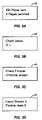
- FIG. 4is a flowchart diagram of one method of practicing the present invention.
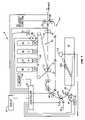
- the present inventionis directed to an image forming device, generally illustrated as 9 in FIG. 1 , that monitors the position of media sheets moving through the image forming process.
- the device 9detects the occurrence of a media jam and determines the position of each media sheet within the device at the time of the jam.
- a messageis displayed to an operator indicating the number of sheets and the access points at which to remove the sheets from the media path. The order of media sheet removal may also be displayed to the operator.
- a plurality of toner cartridges 12 , 14 , 16 , 18each have a corresponding photoconductive drum 13 , 15 , 17 , 19 .
- Each toner cartridgehas a similar construction but is distinguished by the toner color contained therein.
- the device 9includes a black cartridge 18 , a magenta cartridge 16 , a cyan cartridge 14 , and a yellow cartridge 12 .
- the different color tonersform individual images in their respective color that are combined in layered fashion to create the final multicolored image.
- Each photoconductive drum 13 , 15 , 17 , 19has a smooth surface for receiving an electrostatic charge from a laser assembly (not illustrated).
- the drumscontinuously and uniformly rotate past the laser assembly that directs a laser beam onto selected portions of the drum surfaces forming an electrostatic latent image representing the image to be printed.
- the drumis rotated as the laser beam is scanned across its length. This process continues as the entire image is formed on the drum surface.
- the drumsAfter receiving the latent image, the drums rotate past a toner area having a toner bin for housing the toner and a developer roller for uniformly transferring toner to the drum.
- the toneris a fine powder usually composed of plastic granules that are attracted to the electrostatic latent image formed on the drum surface by the laser assembly.
- An intermediate transfer medium (ITM) belt 22receives the toner images from each drum surface.
- the ITM belt 22is endless and extends around a series of rollers adjacent to the drums 13 , 15 , 17 , 19 as it moves in the direction indicated by arrow 23 .
- the ITM belt 22 and drums 13 , 15 , 17 , 19are synchronized providing for the toner image from each drum to precisely align in an overlapping arrangement.
- a multi-color toner imageis formed during a single pass of the ITM belt 22 .
- the yellow (Y) toneris placed first on the ITM belt 22 , followed by cyan (C), magenta (M), and black (K).
- ITM belt 22makes a plurality of passes by the drums to form the overlapping toner image.
- ITM belt 22moves the toner image towards a second transfer point 50 where the toner images are transferred to a media sheet.
- a pair of rollers 25 , 27form a nip where the toner images are transferred from the ITM belt 22 to the media sheet.
- the media sheet with toner imagethen travels through a fuser 49 where the toner is adhered to the media sheet.
- the media sheet with fused imageis then either output to a finisher, exits from the image forming device 9 , or is routed through a duplexer 70 for image formation on a second side.
- Media path 39is formed by a series of nip rollers 33 spaced a distance apart.
- the media path 39extends between the input trays 34 , the second transfer 50 , fuser 49 , duplexer 70 , and finisher or exit.
- the nip rollers 33are rotated by a motor 69 to control the speed and position of each media sheet as it moves along the media path 39 .
- Motor 69in turn is controlled by a controller 42 that oversees the image forming process.
- FIG. 1illustrates one embodiment having a single motor 69 that controls the nip rollers 33 along the media path 39 .
- Various numbers of motors 69may be positioned along the media path 39 to control the media sheets.
- Controller 42oversees the timing of the toner images and the media sheets, and the overall image forming process.
- controller 42includes a microprocessor with associated memory 44 .
- controller 42includes a microprocessor, random access memory, read only memory, and an input/output interface.
- a display 40may further be operatively connected to the controller 42 for displaying messages to an operator.
- the display 40may include an LED or LCD array to display alpha-numeric characters.
- Media sheetsare introduced into the media path 39 in a variety of different manners.
- an input tray 34holds a stack of media sheets, and a pick mechanism 100 picks a topmost sheet from the stack and feeds it towards the media path 39 .
- a drive assembly 110 controlled by controller 42activates the pick mechanism 100 and moves the media sheet into the media path 39 .
- the embodiment illustrated in FIG. 1includes a single input tray 34 . Multiple input trays having various media capacity and being able to hold various media sizes may also be included to introduce media sheets.
- a multi-purpose feeder 38provides another method of introducing media sheets into the media path 39 . Media sheets are manually loaded by an operator into the multi-purpose feeder 38 and rollers 33 move the sheet along the media path 39 .
- sensors S 1 , S 2 , S 3 , S 4are placed along the media path 39 to determine the position of the media sheet.
- sensorsare optical sensors that detect a leading edge or trailing edge of the media sheet when passing the sensor location.
- the sensorsinclude an emitter that transmits a signal and a receiver that receives the signal. The signal is interrupted when the media sheet passes past the sensor thus indicating the location.
- One embodiment of a sensorincludes a light-emitting diode as the emitter and a phototransistor as the receiver.
- sensorsinclude an actuator arm positioned within the media path 39 .
- Movement of the media sheet along the media path 39causes the actuator arm to be pushed aside which either actuates a switch, or is sensed by an emitter/receiver combination as described above.
- a first sensor S 1is placed on the media path upstream from the input tray 34 , a second sensor S 2 downstream from the fuser 49 , a third sensor S 3 at the input of the duplexer 70 , and a fourth sensor S 4 at the exit of the duplexer 70 . Additional sensors may be placed at the input trays 34 . Each sensor is operatively connected to the controller 42 and provides the controller with an accurate location of the media sheets.
- Encoder 61is operatively connected to the controller 42 and ascertains the revolutions and rotational position of the motor 69 .
- Each revolution of the motor 69equates to a predetermined amount of movement of the media sheet along the media path 39 .
- Tracking the revolutions of the motor 69provides for the controller 42 to track the movement and location of each media sheet along the media path 39 when the media sheets are not located at a sensor.
- the position of the media sheets along the media path 39is tracked by the sensors positioned throughout the media path 39 , the speed of the motor 69 , and the feedback from the encoder 61 .
- the controller 42registers the position at the time a media sheet passes through a sensor. Subsequent positions are calculated by monitoring the feedback from the encoder 61 to determine the distance the sheet has moved since being detected by the sensor.
- pick mechanism 100receives a command from the controller 42 to pick a media sheet.
- the media sheetmoves through the beginning of the media path 39 and eventually trips a media path sensor S 1 .
- Controller 42begins tracking incrementally the position of the media sheet by monitoring the feedback of encoder 61 associated with the motor 69 .
- the position of the media sheetis tracked in this manner until the media sheet moves through another sensor. In the embodiment of FIG. 1 , this occurs when the media sheet moves through the fuser 49 and is detected by sensor S 2 .
- the incremental distance of the media sheetis again tracked by monitoring the feedback of the encoder 61 until the next sensor detects the media sheet. In the embodiment of FIG. 1 , this occurs at the entrance of the duplexer 70 by sensor S 3 .
- the position of the media sheetcontinues to be tracked in this manner with the location detected by the sensors, and incremental positions tracked by monitoring the motors 69 and encoders 61 . In another embodiment, the incremental location is determined by monitoring the number of steps taken by the motor 69 since the media sheet has last moved through a sensor.
- Controller 42includes requirements for the sheets to move between points along the media path 39 . Controller 42 determines that a jam has occurred when the media sheet does not pass through the downstream point within the predetermined number of encoder pulses.
- controller 42includes a predetermined number of encoder pulses required for the media sheet to move between sensor S 1 and sensor S 2 . The pulses are counted starting when the media sheet passes through sensor S 1 and the controller 42 determines a jam has occurred if the media sheet has not passed through sensor S 2 within the predetermined number of pulses.
- controller 42stores a time period for the media sheet to move between two points based on the motor speed. A jam is determined if the media sheet does not reach the second point within the predetermined time period.
- the distance monitored by the controller 42may be between adjacent sensors (e.g., S 1 and S 2 ), or between any two sensors on the media path 39 (e.g., S 1 and S 4 ).
- controller 42At the time of a jam, controller 42 ascertains the position of the media sheet.
- the locationmay be determined as a function of the number of encoder pulses since passing the last sensor, or the time and motor speed since passing the last sensor.
- Another method of determining the jam locationis for the controller 42 to be equipped with statistical information indicating the most likely location of a media jam for each predetermined distance. The statistical information is ascertained from diagnostic testing which indicates the most statistically-likely location of the jam.
- the second transfer 50may be the most statistically-likely location of a jam between sensors S 1 and S 2 .
- Controller 42further includes a listing of the access points stored within memory 44 .
- Access pointsare positions on the device 9 where the user can access a media sheet on the media path 39 .
- Access pointsmay include doors, input drawers, or observable points along the media path where the user can access a media sheet.
- One or more access pointsare stored for each location along the media path 39 .
- controllerdetermines the position of each media sheet and displays the corresponding access point for accessing and removing the media sheet.
- the access pointsare prioritized according to the least disruptive to the device 9 , and the most ergonomically straight-forward.
- the controller 42displays the access points in the prioritized order and the operator is to attempt access of the media sheet in that order. If the operator is unable to access the media sheet through the first access point, the second access point may then be used.
- FIG. 2illustrates one embodiment of the exterior of the image forming device 9 and various doors and drawers.
- Access pointsinclude a multipurpose feeder door 102 , left access door 103 ; front access door 105 ; output expander or mailboxer door 110 ; upper right access door 108 ; lower right access door 107 ; duplexer right access door 109 ; duplexer front access door 106 ; first media tray drawer 112 ; left access door 104 ; and second media tray drawer 116 .
- Each of the doors and drawersprovide access to different sections of the media path 39 .
- Least disruptiveis defined as the manner of removing the media sheet that will be the least likely to cause damage to the device or require the least amount of maintenance or operator intervention to correct.
- Controller 42prompts the user to remove the media sheet through the front access door 105 where the media sheet is pulled perpendicularly away from the media path 39 .
- the controller 42does not indicate to access the jammed media through a side door such as the lower right access door 107 or left access door 103 because the media sheet may be pulled through the rollers 25 , 27 or fuser rollers 49 which would smear the unfused toner onto the rollers thus requiring maintenance to clean the rollers prior to the next print job.
- the least disruptive accessis through a side door. Accessing the jam by opening the media drawer could result in the pick mechanism being damaged. This is particularly the case when the media sheet is a transparency that has a higher tear strength than a sheet of paper. Least disruptive also includes removing the media sheet in a manner least likely to tear the media and leave torn sections in the media path. Using the example of a jam at the media drawer, pulling open the media drawer could tear the media sheet leaving a remainder part within the media path at a position that may require disassembly of the device 9 to fully remove the parts. Accessing the media sheet from a side door provides the sheet to be removed without tearing.
- An ergonomically correct solutionis that which provides the most straight-forward access to the media sheet by the operator.
- the corresponding access pointdoes not require the operator to reach into physically-difficult positions.
- An example of the ergonomically correct solution for jam removalmay occur when a media sheet is jammed at the end of the duplexer 70 .
- Controller 42may indicate to remove the sheet through duplexer front access door 106 which provides more straight-forward access to the jam then through duplexer right access door 109 , or left access door 103 .
- Another example of an ergonomic solutionoccurs when a media sheet has just been introduced into the finisher. The ergonomic solution is to separate the finisher from the main body of the device 9 .
- An ergonomic solutionalso accounts for preventing the media sheet from tearing during removal because a remainder of a sheet within the media path 39 may be very difficult to access.
- Controller 42may indicate a single access point to remove the media sheet, or may indicate a plurality of access points. When indicating a plurality of access points, controller 42 will list first the access point that is least disruptive and ergonomically correct manner, and then list other alternatives if removal is unsuccessful.
- the prioritization for removing media sheets from the device 9includes removing the media sheets through the following access points:
- Priority 1multipurpose feeder door 102 , left access door 103 , left access door 104
- Priority 2front access door 105 , duplexer front access door 106 , input drawers 112 , 116
- Priority 3duplexer right access door 109 , lower right access door 107 , upper right access door 108 , output expander or mailboxer door 110
- Controller 42may further prioritize observable points along the media path 39 in addition with the doors and drawers.
- the prioritymay include accessing a particular door, but then removing the media sheet at a particular point on the media path. This is particularly useful when a single door or drawer provides multiple means of access to the media path 39 .
- Multiple media sheetsmay be present throughout the media path 39 at one time, and may be part of a multi-page print job, or multiple print jobs.
- the controller 42monitors the position of each sheet in the same manner as described above. At the occurrence of a jam, controller 42 determines the position of each media sheet along the media path and displays the number of media sheets that should be removed to correct the problem.
- the controller 42may indicate that all media sheets within the media path 39 should be removed, or a number less than all the media sheets are to be removed.
- media sheets within the finishermay not have to be removed to clear the jam, but media sheets within the duplexer path 70 may need to be removed.
- Indicating the number of media sheets to be removedallows the operator to know when he or she has removed all problematic media sheets and printing can resume. Some previous devices do not indicate the number of sheets and the operator either continues looking for non-existent jammed sheets, or closes the door or drawers to reset the device only to later determine that additional sheets are jammed within the media path 39 .
- a first message indicated on the display 40is the location of the media jam.
- the locationmay be written (e.g., duplexer) or may be coded in a manner that can be referenced in a user's guide (e.g., 200 ).
- the messagemay further include the number of problematic media sheets that are to be removed from the media path 39 .
- a second message as illustrated in FIG. 3Bmay include the access points where media sheets can be located along the media path 39 .
- the messagemay further include the recommended order of the access points.
- the media sheetsare to be removed from area D prior to attempting removal through access L.
- a third message as illustrated in FIG. 3Cindicates additional areas that are to be checked along the media path.
- FIG. 3Dillustrates a fourth message indicating that particular sheets are to remain within the media path 39 .
- the display 40may toggle between the messages, to show two or more of the messages.
- Each of the access pointsis identified for the operator.
- a single labelis adhered to the device 9 that maps the locations of the access points.
- Individual labelsmay also be positioned on the device 9 at each of the access points.
- Dis the front access door;
- Ais the multipurpose feeder;
- Bis the left access door, etc.
- the lettering schemeconsists of one letter for each area of the device 9 and T(X) for each media drawer.
- FIG. 4is an example of one method of using the present invention.
- a print requestis received from an operator (step 300 ).
- One or more print requestsmay be processed at one time, and the controller 42 monitors the movement of the media sheets through the media path 39 (step 302 ) and detects a jam (step 304 ).
- the controller 42determines the number of media sheets along the media path 39 that are to be removed as a result of the jam (step 306 ) and the positions of the media sheets that are to be removed (step 308 ).
- Controller 42shows on the display 40 the number of media sheets that are to be removed from the media path 39 and the access points to access and remove each of the media sheets (step 310 ).
- controller 42determines whether the media sheets have been successfully removed (step 314 ). If the jam is removed, the image forming device 9 is reset and another print job may be received (step 320 ). If the media sheets are not successfully removed, a message is displayed on the display 40 notifying the operator. The additional message may provide further jam-clearing information, or may simply indicate that the jam is still present.
- a secondary jam removal messagewill be displayed.
- the controller 42does not display the number of remaining sheets within the media path 39 because there is no manner of determining how many sheets were previously successfully removed by the operator.
- the controller 42will also be unable to display the number of sheets in the media path 39 .
- FIG. 1illustrates one embodiment of the image forming device 9 .
- the embodiment of FIG. 1is a color laser printer, however, the present invention is also applicable to other types of image forming devices that move media sheets during the image formation process.
- the present inventionmay be carried out in other specific ways than those herein set forth without departing from the scope and essential characteristics of the invention.
- the priority of the access pointsis ascertained during testing of the device 9 .
- the embodiment illustrated in FIG. 1comprises separate cartridges for each different color.
- the present inventionis not limited to this embodiment, and may also be applicable to image forming device featuring a single cartridge.
- the present embodimentsare, therefore, to be considered in all respects as illustrative and not restrictive, and all changes coming within the meaning and equivalency range of the appended claims are intended to be embraced therein.
Landscapes
- Physics & Mathematics (AREA)
- General Physics & Mathematics (AREA)
- Accessory Devices And Overall Control Thereof (AREA)
- Control Or Security For Electrophotography (AREA)
- Paper Feeding For Electrophotography (AREA)
Abstract
Description
Claims (13)
Priority Applications (1)
| Application Number | Priority Date | Filing Date | Title |
|---|---|---|---|
| US10/729,210US7127184B2 (en) | 2003-12-05 | 2003-12-05 | Method and device for clearing media jams from an image forming device |
Applications Claiming Priority (1)
| Application Number | Priority Date | Filing Date | Title |
|---|---|---|---|
| US10/729,210US7127184B2 (en) | 2003-12-05 | 2003-12-05 | Method and device for clearing media jams from an image forming device |
Publications (2)
| Publication Number | Publication Date |
|---|---|
| US20050123309A1 US20050123309A1 (en) | 2005-06-09 |
| US7127184B2true US7127184B2 (en) | 2006-10-24 |
Family
ID=34633889
Family Applications (1)
| Application Number | Title | Priority Date | Filing Date |
|---|---|---|---|
| US10/729,210Expired - LifetimeUS7127184B2 (en) | 2003-12-05 | 2003-12-05 | Method and device for clearing media jams from an image forming device |
Country Status (1)
| Country | Link |
|---|---|
| US (1) | US7127184B2 (en) |
Cited By (6)
| Publication number | Priority date | Publication date | Assignee | Title |
|---|---|---|---|---|
| US7421215B2 (en)* | 2004-08-03 | 2008-09-02 | Hewlett-Packard Development Company, L.P. | Method and apparatus for detecting a media jam |
| US20090141301A1 (en)* | 2007-12-03 | 2009-06-04 | Oce-Technologies B.V | Printing device |
| US20100164171A1 (en)* | 2008-12-30 | 2010-07-01 | Konica Minolta Systems Laboratory, Inc. | Method and apparatus for clearing paper jam in a printing device |
| US20140077450A1 (en)* | 2012-09-20 | 2014-03-20 | Riso Kagaku Corporation | Paper conveying device |
| CN104149498A (en)* | 2013-05-14 | 2014-11-19 | 佳能株式会社 | Printing apparatus and control method thereof |
| US11055037B2 (en) | 2019-09-26 | 2021-07-06 | Ricoh Company, Ltd. | Enhanced printer and printer operator interactions |
Families Citing this family (8)
| Publication number | Priority date | Publication date | Assignee | Title |
|---|---|---|---|---|
| JP4537213B2 (en)* | 2005-01-14 | 2010-09-01 | 株式会社Pfu | Sheet feeding device |
| US7613406B2 (en)* | 2005-04-28 | 2009-11-03 | Canon Kabushiki Kaisha | Image forming apparatus that detects a presence of a conductive foreign object on a recording material |
| US20090310982A1 (en)* | 2008-06-16 | 2009-12-17 | Kabushiki Kaisha Toshiba | Image forming apparatus and control method for image forming apparatus |
| JP4737566B2 (en)* | 2008-07-28 | 2011-08-03 | ブラザー工業株式会社 | Image forming apparatus |
| KR101532604B1 (en)* | 2008-09-29 | 2015-06-30 | 삼성전자주식회사 | A paper jam processing method for an image forming apparatus having at least one optional cassette and an image forming apparatus |
| US8926062B2 (en)* | 2010-10-18 | 2015-01-06 | Hewlett-Packard Development Company, L.P. | Printers and duplexers for printers |
| JP6631140B2 (en)* | 2015-05-14 | 2020-01-15 | 株式会社リコー | Image forming apparatus and image forming method |
| JP2019120735A (en)* | 2017-12-28 | 2019-07-22 | 京セラドキュメントソリューションズ株式会社 | Image forming apparatus |
Citations (79)
| Publication number | Priority date | Publication date | Assignee | Title |
|---|---|---|---|---|
| US4176941A (en)* | 1978-02-27 | 1979-12-04 | Van Dyk Research Corporation | Malfunction display system for electrophotographic copying machines |
| US4320953A (en) | 1977-12-07 | 1982-03-23 | Savin Corporation | Pick-off device for electrostatic copier |
| US4360279A (en) | 1980-07-02 | 1982-11-23 | Brother Kogyo Kabushiki Kaisha | Printing paper feeding mechanism |
| US4411511A (en) | 1979-12-20 | 1983-10-25 | Ricoh Company, Ltd. | Image transfer material separation and transportation apparatus for electrophotographic copying apparatus |
| US4566684A (en) | 1984-01-12 | 1986-01-28 | National Computer Systems | Automatic sheet feed mechanism |
| US4577849A (en) | 1982-05-31 | 1986-03-25 | Tokyo Shibaura Denki Kabushiki Kaisha | Multiple source paper conveyor system |
| US4580917A (en) | 1983-10-03 | 1986-04-08 | Alps Electric Co. Ltd. | Paper feed apparatus for printer |
| US4589765A (en) | 1985-05-22 | 1986-05-20 | Xerox Corporation | Sheet feeder control for reproduction machines |
| US4627711A (en) | 1985-09-30 | 1986-12-09 | Xerox Corporation | Machine shutdown control |
| US4660821A (en) | 1983-06-08 | 1987-04-28 | Yoshida Kogyo K.K. | Method of and apparatus for attaching fly strips to a slide fastener chain |
| US4682158A (en) | 1984-03-23 | 1987-07-21 | Ricoh Company, Ltd. | Guidance device for manipulation of machine |
| US4682769A (en) | 1983-08-26 | 1987-07-28 | Kabushiki Kaisha Toshiba | Sheet supplying apparatus |
| US4744687A (en) | 1984-09-29 | 1988-05-17 | Ricoh Company, Ltd. | Paper feed roller drive system for a printer |
| US4766463A (en) | 1986-06-20 | 1988-08-23 | Ricoh Company, Ltd. | Image forming apparatus |
| US4809969A (en) | 1982-12-13 | 1989-03-07 | Savin Corporation | Automatic document feeder and registration system therefor |
| US4868609A (en) | 1987-05-16 | 1989-09-19 | Minolta Camera Kabushiki Kaisha | Apparatus for transporting sheets of paper |
| US4884796A (en) | 1988-05-26 | 1989-12-05 | Daboub Henry A | Singulator for document feeder |
| US4900003A (en) | 1987-11-09 | 1990-02-13 | Canon Kabushiki Kaisha | Sheet conveying apparatus |
| US4908655A (en) | 1987-04-14 | 1990-03-13 | Fuji Photo Film Co., Ltd. | Jam detecting and displaying device in an image recording apparatus |
| US4919318A (en) | 1988-04-18 | 1990-04-24 | Xerox Corporation | Swing arm roller speed differential web tracking system |
| US4990011A (en) | 1989-09-21 | 1991-02-05 | Hewlett-Packard Company | Sheet alignment using reverse advance roll and stationary pick roll |
| US5034780A (en) | 1988-09-30 | 1991-07-23 | Ricoh Company, Ltd. | Image forming apparatus |
| US5056771A (en) | 1989-08-25 | 1991-10-15 | Lexmark International, Inc. | Apparatus for controlling interpage gaps in printers and method of interpage gap control |
| US5081508A (en)* | 1989-11-09 | 1992-01-14 | Fuji Xerox Co., Ltd. | Paper-jam detecting device |
| US5121915A (en) | 1989-11-20 | 1992-06-16 | International Business Machines Corporation | Document processor having improved throughput capabilities |
| US5121914A (en) | 1989-10-27 | 1992-06-16 | Hargreaves Edward W | Apparatus for controlling the spacing, counting and batching of sheets fed by a machine |
| US5141217A (en) | 1990-07-07 | 1992-08-25 | Samsung Electronics Co., Ltd. | Device for feeding paper for use in a facsimile |
| US5164770A (en) | 1978-12-08 | 1992-11-17 | Canon Kabushiki Kaisha | Image forming apparatus having feeding error detection and feeding error display |
| US5171977A (en) | 1990-05-14 | 1992-12-15 | Sunquest Information Systems, Inc. | Portable medical specimen data collection system |
| US5182597A (en) | 1978-10-15 | 1993-01-26 | Canon Kabushiki Kaisha | Image forming device |
| US5197726A (en) | 1991-09-26 | 1993-03-30 | Fuji Xerox Co., Ltd. | Sheet feeder |
| US5253862A (en) | 1991-12-23 | 1993-10-19 | Xerox Corporation | Adjustable normal force edge registering apparatus |
| US5277415A (en) | 1991-10-31 | 1994-01-11 | Brother Kogyo Kabushiki Kaisha | Sheet feeding device |
| US5280322A (en) | 1991-03-12 | 1994-01-18 | Mita Industrial Co., Ltd. | Image forming apparatus with sheet jam detection |
| US5393044A (en) | 1992-12-04 | 1995-02-28 | Sharp Kabushiki Kaisha | Paper feeder |
| US5414495A (en) | 1994-01-04 | 1995-05-09 | Xerox Corporation | Control for induced jam of selected zone of machine |
| US5423527A (en) | 1993-11-05 | 1995-06-13 | Unisys Corporation | Document transport with gap adjust |
| US5465955A (en) | 1994-08-08 | 1995-11-14 | Bayer Corporation | Method and apparatus for an external media buffer |
| US5495326A (en) | 1991-04-26 | 1996-02-27 | Sanyo Electric Co., Ltd. | Sheet feeding control for an image forming apparatus |
| US5499091A (en)* | 1993-04-19 | 1996-03-12 | Canon Kabushiki Kaisha | Image forming apparatus having a counting device to facilitate two-sided copying |
| US5501444A (en) | 1993-01-18 | 1996-03-26 | Canon Kabushiki Kaisha | Sheet supply apparatus |
| US5507478A (en) | 1994-09-20 | 1996-04-16 | Hewlett-Packard Company | Printing media status sensing |
| US5580046A (en) | 1995-01-31 | 1996-12-03 | Hewlett-Packard Company | Selective ejection of sensed paper jams in single sheet paper processing equipment |
| US5601283A (en) | 1996-01-11 | 1997-02-11 | Xerox Corporation | Cross roll registration deskew based on paper weight |
| US5602625A (en) | 1994-08-31 | 1997-02-11 | Sharp Kabushiki Kaisha | Operation guidance display apparatus of image forming apparatus |
| US5651538A (en) | 1994-11-02 | 1997-07-29 | Samsung Electronics Co., Ltd. | Paper feeding method of an image forming apparatus |
| US5667215A (en) | 1994-09-16 | 1997-09-16 | Kabushiki Kaisha Toshiba | Paper conveying device |
| US5692741A (en) | 1993-03-10 | 1997-12-02 | Minolta Camera Kabushiki Kaisha | Method and apparatus for feeding sheets based on comparison of actual travel time and reference travel time |
| US5790916A (en)* | 1995-08-07 | 1998-08-04 | Ricoh Company, Ltd. | Image forming apparatus and service system therefor |
| US5815766A (en)* | 1997-03-31 | 1998-09-29 | Xerox Corporation | Method and apparatus for clean convenient copy sheet jam clearance in an electrostatographic machine |
| US5826135A (en) | 1995-05-31 | 1998-10-20 | Samsung Electronics Co., Ltd. | Paper feeding control method of an image forming apparatus |
| US5878321A (en) | 1996-11-16 | 1999-03-02 | Mita Industrial Co., Ltd. | Image-forming machine |
| US5878302A (en)* | 1997-03-12 | 1999-03-02 | Minolta Co., Ltd. | Image forming apparatus informing internal abnormality |
| US5893657A (en)* | 1992-12-28 | 1999-04-13 | Canon Kabushiki Kaisha | Image forming apparatus with sheet conveying apparatus that facilitates jam recovery |
| US5937245A (en)* | 1996-12-13 | 1999-08-10 | Canon Kabushiki Kaisha | Image forming apparatus having an improved system for removing residual toner |
| US5970277A (en) | 1998-02-16 | 1999-10-19 | Konica Corporation | Image forming apparatus |
| US5970274A (en) | 1998-11-06 | 1999-10-19 | Xerox Corporation | Jam detection system |
| JPH11334181A (en)* | 1998-05-26 | 1999-12-07 | Canon Inc | Image forming device |
| US6011936A (en) | 1995-05-16 | 2000-01-04 | Canon Kabushiki Kaisha | Image forming apparatus having recovery process for jammed sheets |
| US6076821A (en) | 1998-09-14 | 2000-06-20 | Lexmark International, Inc. | Method and apparatus for feeding sheets |
| USRE37007E1 (en) | 1989-12-07 | 2001-01-02 | Mars Incorporated | Device for aligning sheets with plural drive roller groups on a common shaft |
| US6170816B1 (en) | 1996-02-27 | 2001-01-09 | Siemens Aktiengesellschaft | Method of controlling a device for removing flat items of post from a stack |
| US6173952B1 (en) | 1999-05-17 | 2001-01-16 | Xerox Corporation | Printer sheet deskewing system with automatic variable nip lateral spacing for different sheet sizes |
| US6205297B1 (en)* | 1995-10-09 | 2001-03-20 | Canon Kabushiki Kaisha | Recording apparatus with automatic paper discharge and fixing roller temperature control features |
| US6273418B1 (en) | 1997-12-26 | 2001-08-14 | Fuji Xerox Co., Ltd. | Sheet registration device and an image forming apparatus having the same |
| US6330424B1 (en) | 2000-11-21 | 2001-12-11 | Lexmark International, Inc. | Method and apparatus for minimizing the open loop paper positional error in a control system for an electrophotographic printing apparatus |
| US20020009302A1 (en) | 2000-06-26 | 2002-01-24 | Sharp Kabushiki Kaisha | Abnormality displaying apparatus for use in image forming apparatus |
| US6375180B1 (en) | 1999-05-19 | 2002-04-23 | Konica Corporation | Sheet finisher, image forming apparatus, and sheet conveyance apparatus |
| US6381422B1 (en) | 2000-07-31 | 2002-04-30 | Toshiba Tec Kabushiki Kaisha | Image forming apparatus for fine-adjusting a fixation speed of a development material in accordance with temperature control |
| US6385406B1 (en) | 1999-04-15 | 2002-05-07 | Canon Kabushiki Kaisha | Sheet detecting apparatus with correction means for sheet surface condition and sheet thickness |
| US6382618B1 (en) | 1999-05-25 | 2002-05-07 | Canon Kabushiki Kaisha | Sheet conveying apparatus and image forming apparatus |
| US6446954B1 (en) | 2000-09-27 | 2002-09-10 | Hewlett-Packard Company | Method and apparatus for end-to-end feeding of sheet media |
| US6519443B1 (en) | 2001-10-02 | 2003-02-11 | Lexmark International, Inc. | Method for calculating a print medium pick time for an imaging apparatus that transports print media at variable speeds |
| US6533268B2 (en) | 2001-07-27 | 2003-03-18 | Xerox Corporation | Printer sheet lateral registration and deskewing system |
| US6560415B2 (en)* | 2000-12-08 | 2003-05-06 | Fuji Xerox Co., Ltd. | Image formation apparatus and method for controlling a paper stop position |
| US6575458B2 (en) | 2001-07-27 | 2003-06-10 | Xerox Corporation | Printer sheet deskewing system |
| US6578844B2 (en) | 2001-04-10 | 2003-06-17 | Xerox Corporation | Sheet feeder |
| US6658218B2 (en)* | 2001-12-28 | 2003-12-02 | Xerox Corporation | Illuminated components for guiding maintenance and repair sequence |
| US6898382B2 (en)* | 2002-04-08 | 2005-05-24 | Canon Kabushiki Kaisha | Image forming apparatus |
- 2003
- 2003-12-05USUS10/729,210patent/US7127184B2/ennot_activeExpired - Lifetime
Patent Citations (81)
| Publication number | Priority date | Publication date | Assignee | Title |
|---|---|---|---|---|
| US4320953A (en) | 1977-12-07 | 1982-03-23 | Savin Corporation | Pick-off device for electrostatic copier |
| US4176941A (en)* | 1978-02-27 | 1979-12-04 | Van Dyk Research Corporation | Malfunction display system for electrophotographic copying machines |
| US5182597A (en) | 1978-10-15 | 1993-01-26 | Canon Kabushiki Kaisha | Image forming device |
| US5164770A (en) | 1978-12-08 | 1992-11-17 | Canon Kabushiki Kaisha | Image forming apparatus having feeding error detection and feeding error display |
| US4411511A (en) | 1979-12-20 | 1983-10-25 | Ricoh Company, Ltd. | Image transfer material separation and transportation apparatus for electrophotographic copying apparatus |
| US4360279A (en) | 1980-07-02 | 1982-11-23 | Brother Kogyo Kabushiki Kaisha | Printing paper feeding mechanism |
| US4577849A (en) | 1982-05-31 | 1986-03-25 | Tokyo Shibaura Denki Kabushiki Kaisha | Multiple source paper conveyor system |
| US4809969A (en) | 1982-12-13 | 1989-03-07 | Savin Corporation | Automatic document feeder and registration system therefor |
| US4660821A (en) | 1983-06-08 | 1987-04-28 | Yoshida Kogyo K.K. | Method of and apparatus for attaching fly strips to a slide fastener chain |
| US4790524A (en) | 1983-08-26 | 1988-12-13 | Kabushiki Kaisha Toshiba | Sheet supplying apparatus |
| US4682769A (en) | 1983-08-26 | 1987-07-28 | Kabushiki Kaisha Toshiba | Sheet supplying apparatus |
| US4580917A (en) | 1983-10-03 | 1986-04-08 | Alps Electric Co. Ltd. | Paper feed apparatus for printer |
| US4566684A (en) | 1984-01-12 | 1986-01-28 | National Computer Systems | Automatic sheet feed mechanism |
| US4682158A (en) | 1984-03-23 | 1987-07-21 | Ricoh Company, Ltd. | Guidance device for manipulation of machine |
| US4744687A (en) | 1984-09-29 | 1988-05-17 | Ricoh Company, Ltd. | Paper feed roller drive system for a printer |
| US4589765A (en) | 1985-05-22 | 1986-05-20 | Xerox Corporation | Sheet feeder control for reproduction machines |
| US4627711A (en) | 1985-09-30 | 1986-12-09 | Xerox Corporation | Machine shutdown control |
| US4766463A (en) | 1986-06-20 | 1988-08-23 | Ricoh Company, Ltd. | Image forming apparatus |
| US4996557A (en) | 1987-04-14 | 1991-02-26 | Fuji Photo Film Co., Ltd. | Jam detecting and displaying device in an image recording apparatus |
| US4908655A (en) | 1987-04-14 | 1990-03-13 | Fuji Photo Film Co., Ltd. | Jam detecting and displaying device in an image recording apparatus |
| US4868609A (en) | 1987-05-16 | 1989-09-19 | Minolta Camera Kabushiki Kaisha | Apparatus for transporting sheets of paper |
| US4900003A (en) | 1987-11-09 | 1990-02-13 | Canon Kabushiki Kaisha | Sheet conveying apparatus |
| US4919318A (en) | 1988-04-18 | 1990-04-24 | Xerox Corporation | Swing arm roller speed differential web tracking system |
| US4884796A (en) | 1988-05-26 | 1989-12-05 | Daboub Henry A | Singulator for document feeder |
| US5034780A (en) | 1988-09-30 | 1991-07-23 | Ricoh Company, Ltd. | Image forming apparatus |
| US5056771A (en) | 1989-08-25 | 1991-10-15 | Lexmark International, Inc. | Apparatus for controlling interpage gaps in printers and method of interpage gap control |
| US4990011A (en) | 1989-09-21 | 1991-02-05 | Hewlett-Packard Company | Sheet alignment using reverse advance roll and stationary pick roll |
| US5121914A (en) | 1989-10-27 | 1992-06-16 | Hargreaves Edward W | Apparatus for controlling the spacing, counting and batching of sheets fed by a machine |
| US5081508A (en)* | 1989-11-09 | 1992-01-14 | Fuji Xerox Co., Ltd. | Paper-jam detecting device |
| US5121915A (en) | 1989-11-20 | 1992-06-16 | International Business Machines Corporation | Document processor having improved throughput capabilities |
| USRE37007E1 (en) | 1989-12-07 | 2001-01-02 | Mars Incorporated | Device for aligning sheets with plural drive roller groups on a common shaft |
| US5171977A (en) | 1990-05-14 | 1992-12-15 | Sunquest Information Systems, Inc. | Portable medical specimen data collection system |
| US5141217A (en) | 1990-07-07 | 1992-08-25 | Samsung Electronics Co., Ltd. | Device for feeding paper for use in a facsimile |
| US5280322A (en) | 1991-03-12 | 1994-01-18 | Mita Industrial Co., Ltd. | Image forming apparatus with sheet jam detection |
| US5495326A (en) | 1991-04-26 | 1996-02-27 | Sanyo Electric Co., Ltd. | Sheet feeding control for an image forming apparatus |
| US5197726A (en) | 1991-09-26 | 1993-03-30 | Fuji Xerox Co., Ltd. | Sheet feeder |
| US5277415A (en) | 1991-10-31 | 1994-01-11 | Brother Kogyo Kabushiki Kaisha | Sheet feeding device |
| US5253862A (en) | 1991-12-23 | 1993-10-19 | Xerox Corporation | Adjustable normal force edge registering apparatus |
| US5393044A (en) | 1992-12-04 | 1995-02-28 | Sharp Kabushiki Kaisha | Paper feeder |
| US5893657A (en)* | 1992-12-28 | 1999-04-13 | Canon Kabushiki Kaisha | Image forming apparatus with sheet conveying apparatus that facilitates jam recovery |
| US5501444A (en) | 1993-01-18 | 1996-03-26 | Canon Kabushiki Kaisha | Sheet supply apparatus |
| US5692741A (en) | 1993-03-10 | 1997-12-02 | Minolta Camera Kabushiki Kaisha | Method and apparatus for feeding sheets based on comparison of actual travel time and reference travel time |
| US5499091A (en)* | 1993-04-19 | 1996-03-12 | Canon Kabushiki Kaisha | Image forming apparatus having a counting device to facilitate two-sided copying |
| US5423527A (en) | 1993-11-05 | 1995-06-13 | Unisys Corporation | Document transport with gap adjust |
| US5414495A (en) | 1994-01-04 | 1995-05-09 | Xerox Corporation | Control for induced jam of selected zone of machine |
| US5465955A (en) | 1994-08-08 | 1995-11-14 | Bayer Corporation | Method and apparatus for an external media buffer |
| US5602625A (en) | 1994-08-31 | 1997-02-11 | Sharp Kabushiki Kaisha | Operation guidance display apparatus of image forming apparatus |
| US5667215A (en) | 1994-09-16 | 1997-09-16 | Kabushiki Kaisha Toshiba | Paper conveying device |
| US5507478A (en) | 1994-09-20 | 1996-04-16 | Hewlett-Packard Company | Printing media status sensing |
| US5651538A (en) | 1994-11-02 | 1997-07-29 | Samsung Electronics Co., Ltd. | Paper feeding method of an image forming apparatus |
| US5580046A (en) | 1995-01-31 | 1996-12-03 | Hewlett-Packard Company | Selective ejection of sensed paper jams in single sheet paper processing equipment |
| US6011936A (en) | 1995-05-16 | 2000-01-04 | Canon Kabushiki Kaisha | Image forming apparatus having recovery process for jammed sheets |
| US5826135A (en) | 1995-05-31 | 1998-10-20 | Samsung Electronics Co., Ltd. | Paper feeding control method of an image forming apparatus |
| US5790916A (en)* | 1995-08-07 | 1998-08-04 | Ricoh Company, Ltd. | Image forming apparatus and service system therefor |
| US6205297B1 (en)* | 1995-10-09 | 2001-03-20 | Canon Kabushiki Kaisha | Recording apparatus with automatic paper discharge and fixing roller temperature control features |
| US5601283A (en) | 1996-01-11 | 1997-02-11 | Xerox Corporation | Cross roll registration deskew based on paper weight |
| US6170816B1 (en) | 1996-02-27 | 2001-01-09 | Siemens Aktiengesellschaft | Method of controlling a device for removing flat items of post from a stack |
| US5878321A (en) | 1996-11-16 | 1999-03-02 | Mita Industrial Co., Ltd. | Image-forming machine |
| US5937245A (en)* | 1996-12-13 | 1999-08-10 | Canon Kabushiki Kaisha | Image forming apparatus having an improved system for removing residual toner |
| US5878302A (en)* | 1997-03-12 | 1999-03-02 | Minolta Co., Ltd. | Image forming apparatus informing internal abnormality |
| US5815766A (en)* | 1997-03-31 | 1998-09-29 | Xerox Corporation | Method and apparatus for clean convenient copy sheet jam clearance in an electrostatographic machine |
| US6273418B1 (en) | 1997-12-26 | 2001-08-14 | Fuji Xerox Co., Ltd. | Sheet registration device and an image forming apparatus having the same |
| US5970277A (en) | 1998-02-16 | 1999-10-19 | Konica Corporation | Image forming apparatus |
| JPH11334181A (en)* | 1998-05-26 | 1999-12-07 | Canon Inc | Image forming device |
| US6076821A (en) | 1998-09-14 | 2000-06-20 | Lexmark International, Inc. | Method and apparatus for feeding sheets |
| US5970274A (en) | 1998-11-06 | 1999-10-19 | Xerox Corporation | Jam detection system |
| US6385406B1 (en) | 1999-04-15 | 2002-05-07 | Canon Kabushiki Kaisha | Sheet detecting apparatus with correction means for sheet surface condition and sheet thickness |
| US6173952B1 (en) | 1999-05-17 | 2001-01-16 | Xerox Corporation | Printer sheet deskewing system with automatic variable nip lateral spacing for different sheet sizes |
| US6375180B1 (en) | 1999-05-19 | 2002-04-23 | Konica Corporation | Sheet finisher, image forming apparatus, and sheet conveyance apparatus |
| US6382618B1 (en) | 1999-05-25 | 2002-05-07 | Canon Kabushiki Kaisha | Sheet conveying apparatus and image forming apparatus |
| US20020009302A1 (en) | 2000-06-26 | 2002-01-24 | Sharp Kabushiki Kaisha | Abnormality displaying apparatus for use in image forming apparatus |
| US6381422B1 (en) | 2000-07-31 | 2002-04-30 | Toshiba Tec Kabushiki Kaisha | Image forming apparatus for fine-adjusting a fixation speed of a development material in accordance with temperature control |
| US6446954B1 (en) | 2000-09-27 | 2002-09-10 | Hewlett-Packard Company | Method and apparatus for end-to-end feeding of sheet media |
| US6330424B1 (en) | 2000-11-21 | 2001-12-11 | Lexmark International, Inc. | Method and apparatus for minimizing the open loop paper positional error in a control system for an electrophotographic printing apparatus |
| US6560415B2 (en)* | 2000-12-08 | 2003-05-06 | Fuji Xerox Co., Ltd. | Image formation apparatus and method for controlling a paper stop position |
| US6578844B2 (en) | 2001-04-10 | 2003-06-17 | Xerox Corporation | Sheet feeder |
| US6533268B2 (en) | 2001-07-27 | 2003-03-18 | Xerox Corporation | Printer sheet lateral registration and deskewing system |
| US6575458B2 (en) | 2001-07-27 | 2003-06-10 | Xerox Corporation | Printer sheet deskewing system |
| US6519443B1 (en) | 2001-10-02 | 2003-02-11 | Lexmark International, Inc. | Method for calculating a print medium pick time for an imaging apparatus that transports print media at variable speeds |
| US6658218B2 (en)* | 2001-12-28 | 2003-12-02 | Xerox Corporation | Illuminated components for guiding maintenance and repair sequence |
| US6898382B2 (en)* | 2002-04-08 | 2005-05-24 | Canon Kabushiki Kaisha | Image forming apparatus |
Cited By (10)
| Publication number | Priority date | Publication date | Assignee | Title |
|---|---|---|---|---|
| US7421215B2 (en)* | 2004-08-03 | 2008-09-02 | Hewlett-Packard Development Company, L.P. | Method and apparatus for detecting a media jam |
| US20090141301A1 (en)* | 2007-12-03 | 2009-06-04 | Oce-Technologies B.V | Printing device |
| US8441658B2 (en)* | 2007-12-03 | 2013-05-14 | Oce-Technologies B.V. | Printing device |
| US20100164171A1 (en)* | 2008-12-30 | 2010-07-01 | Konica Minolta Systems Laboratory, Inc. | Method and apparatus for clearing paper jam in a printing device |
| US20140077450A1 (en)* | 2012-09-20 | 2014-03-20 | Riso Kagaku Corporation | Paper conveying device |
| US8800989B2 (en)* | 2012-09-20 | 2014-08-12 | Riso Kagaku Corporation | Paper conveying device |
| CN104149498A (en)* | 2013-05-14 | 2014-11-19 | 佳能株式会社 | Printing apparatus and control method thereof |
| US20140339756A1 (en)* | 2013-05-14 | 2014-11-20 | Canon Kabushiki Kaisha | Printing apparatus and control method thereof |
| US9156644B2 (en)* | 2013-05-14 | 2015-10-13 | Canon Kabushiki Kaisha | Printing apparatus and control method thereof |
| US11055037B2 (en) | 2019-09-26 | 2021-07-06 | Ricoh Company, Ltd. | Enhanced printer and printer operator interactions |
Also Published As
| Publication number | Publication date |
|---|---|
| US20050123309A1 (en) | 2005-06-09 |
Similar Documents
| Publication | Publication Date | Title |
|---|---|---|
| US7127184B2 (en) | Method and device for clearing media jams from an image forming device | |
| US6011936A (en) | Image forming apparatus having recovery process for jammed sheets | |
| US9104164B2 (en) | Medium carrying device, image forming device, and medium carrying method | |
| US11480908B2 (en) | Post-processing apparatus | |
| JP2002006687A (en) | Error display device for image forming equipment | |
| US5534976A (en) | Method for eliminating a paper jam of an image forming system and apparatus therefor | |
| US8023837B2 (en) | Image forming apparatus capable of preventing a sheet jamming during detected abnormal situations | |
| JP5245511B2 (en) | Image forming apparatus | |
| US4954848A (en) | Control apparatus for a two-sided/multiple copy conveying unit | |
| US8622386B2 (en) | Sheet storage apparatus and image forming apparatus | |
| EP0661605B1 (en) | Control for induced jam of selected zone of machine | |
| JP2005022792A (en) | Sheet feeding device | |
| JP2002268299A (en) | Image forming device | |
| US5809391A (en) | Image forming apparatus enabling easy and reliable recovery from a pop jam | |
| JP3658021B2 (en) | Image forming apparatus | |
| US8297612B2 (en) | Apparatus for detecting media edges in a media input tray | |
| JP7254491B2 (en) | image forming system | |
| JPH07215533A (en) | Image forming device and jam process control method thereof | |
| JP2020050488A (en) | Carrier device, image forming apparatus, and image forming system | |
| JP2011063398A (en) | Image forming device | |
| JP7243261B2 (en) | image forming device | |
| US9981818B2 (en) | Image forming apparatus | |
| US7167673B2 (en) | Method and apparatus for using continuous media stock in a cut-sheet image forming device | |
| KR20240159378A (en) | Apparatus for supporting function of securing printing | |
| JPH0990824A (en) | Image forming device |
Legal Events
| Date | Code | Title | Description |
|---|---|---|---|
| AS | Assignment | Owner name:LEXMARK INTERNATIONAL, INC., KENTUCKY Free format text:ASSIGNMENT OF ASSIGNORS INTEREST;ASSIGNORS:CORIALE, MATTHEW CHRISTOPHER;ELLIOTT, DELBERT LESTER;MAUL, MICHAEL DAVID;AND OTHERS;REEL/FRAME:014776/0147 Effective date:20031203 | |
| STCF | Information on status: patent grant | Free format text:PATENTED CASE | |
| FPAY | Fee payment | Year of fee payment:4 | |
| FPAY | Fee payment | Year of fee payment:8 | |
| MAFP | Maintenance fee payment | Free format text:PAYMENT OF MAINTENANCE FEE, 12TH YEAR, LARGE ENTITY (ORIGINAL EVENT CODE: M1553) Year of fee payment:12 | |
| AS | Assignment | Owner name:CHINA CITIC BANK CORPORATION LIMITED, GUANGZHOU BR Free format text:PATENT SECURITY AGREEMENT;ASSIGNOR:LEXMARK INTERNATIONAL, INC.;REEL/FRAME:046989/0396 Effective date:20180402 | |
| AS | Assignment | Owner name:CHINA CITIC BANK CORPORATION LIMITED, GUANGZHOU BR Free format text:CORRECTIVE ASSIGNMENT TO CORRECT THE INCORRECT U.S. PATENT NUMBER PREVIOUSLY RECORDED AT REEL: 046989 FRAME: 0396. ASSIGNOR(S) HEREBY CONFIRMS THE PATENT SECURITY AGREEMENT;ASSIGNOR:LEXMARK INTERNATIONAL, INC.;REEL/FRAME:047760/0795 Effective date:20180402 | |
| AS | Assignment | Owner name:LEXMARK INTERNATIONAL, INC., KENTUCKY Free format text:RELEASE BY SECURED PARTY;ASSIGNOR:CHINA CITIC BANK CORPORATION LIMITED, GUANGZHOU BRANCH, AS COLLATERAL AGENT;REEL/FRAME:066345/0026 Effective date:20220713 |