US7126440B2 - Modular frequency division filter - Google Patents
Modular frequency division filterDownload PDFInfo
- Publication number
- US7126440B2 US7126440B2US10/899,556US89955604AUS7126440B2US 7126440 B2US7126440 B2US 7126440B2US 89955604 AUS89955604 AUS 89955604AUS 7126440 B2US7126440 B2US 7126440B2
- Authority
- US
- United States
- Prior art keywords
- filter
- transmission paths
- duplexer
- band pass
- frequency
- Prior art date
- Legal status (The legal status is an assumption and is not a legal conclusion. Google has not performed a legal analysis and makes no representation as to the accuracy of the status listed.)
- Expired - Lifetime, expires
Links
- 230000005540biological transmissionEffects0.000claimsabstractdescription57
- 238000000926separation methodMethods0.000abstractdescription5
- 230000001413cellular effectEffects0.000description27
- 241001611138IsmaSpecies0.000description6
- 238000000034methodMethods0.000description5
- 239000003990capacitorSubstances0.000description3
- 238000010586diagramMethods0.000description3
- 230000010363phase shiftEffects0.000description2
- 230000000694effectsEffects0.000description1
Images


Classifications
- H—ELECTRICITY
- H04—ELECTRIC COMMUNICATION TECHNIQUE
- H04B—TRANSMISSION
- H04B1/00—Details of transmission systems, not covered by a single one of groups H04B3/00 - H04B13/00; Details of transmission systems not characterised by the medium used for transmission
- H04B1/005—Details of transmission systems, not covered by a single one of groups H04B3/00 - H04B13/00; Details of transmission systems not characterised by the medium used for transmission adapting radio receivers, transmitters andtransceivers for operation on two or more bands, i.e. frequency ranges
- H04B1/0053—Details of transmission systems, not covered by a single one of groups H04B3/00 - H04B13/00; Details of transmission systems not characterised by the medium used for transmission adapting radio receivers, transmitters andtransceivers for operation on two or more bands, i.e. frequency ranges with common antenna for more than one band
- H04B1/0057—Details of transmission systems, not covered by a single one of groups H04B3/00 - H04B13/00; Details of transmission systems not characterised by the medium used for transmission adapting radio receivers, transmitters andtransceivers for operation on two or more bands, i.e. frequency ranges with common antenna for more than one band using diplexing or multiplexing filters for selecting the desired band
Definitions
- Handsetsare increasing in complexity as handsets incorporate more types of service. In most of the world, the trend is for a handset to work with numerous frequency division transceivers as well as time division transceivers. Handsets will combine both radio bands designed for high speed handovers from cell site to cell site, as well as fixed stations such as wireless local area networks (WLAN). There are also location services, e.g. Global Positioning Satellite (GPS), which require support from the handsets. Depending upon requirements, these functions can be separated using switches, separate antennas, filters, or some combination of these.
- GPSGlobal Positioning Satellite
- the present inventionprovides a cellular handset to require only a single antenna for transceiving between multiple frequency bands.
- the antennaconnects to a modular frequency division filter that includes two or three transmission paths. Each transmission path includes either a band pass filter or a duplexer to separate the received signal by frequency. Frequency phase shifters or shunt inductors may be included to further enhance the frequency separation. Following frequency separating the separated signal is transceived by a device operating at the respective separated frequency.
- the modular frequency division filterincludes three transmission paths.
- Each transmission pathincludes a band pass filter.
- the first band pass filteroperates in the PCS band.
- the second band pass filteroperates in the Cellular Band.
- the third band pass filterpasses a third frequency band, e.g. GPS, ISMa, or ISMb/g. This would be refered to as a triplexer.
- One of the three transmission pathscould lead instead to a duplexer, resulting in a form of the four-frequency embodiment, or quadriplexer.
- Twocould be duplexers, resulting in a form of the five-frequency embodiment, or quintplexer.
- Threecould be duplexers, resulting in a form of the six-frequency embodiment.
- onecould be a triplexer, resulting in a form of the four-frequency embodiment. This process can be applied recursively.
- the modular frequency division filterincludes two transmission paths.
- Each of the transmission pathsinclude a duplexer.
- the first duplexerreceives the receiving frequency for the PCS band and transmits the transmitting frequency for the PCS band.
- the second duplexerreceives the receiving frequency for the Cellular Band and transmits the transmitting frequency for the Cellular Band, for instance.
- the modular frequency division filterincludes three transmission paths. Two of the transmission paths include duplexers. The first duplexer receives the receiving frequency for the PCS band and transmits the transmitting frequency for the PCS band. The second duplexer receives the receiving frequency for the Cellular Band and transmits the transmitting frequency for the Cellular Band.
- the third transmission pathincludes a band pass filter. The band pass filter passes a fifth frequency band, e.g. GPS(1575 MHz), ISMa, or ISMb/g.
- FIGS. 1 a–eillustrate prior art duplexers.
- FIG. 2an embodiment of the present invention.
- FIGS. 3 a and 3 billustrate embodiments of the filter section shown in FIG. 2 .
- FIG. 4illustrates a quadriplexer embodiment of the present invention.
- FIG. 5illustrates the filter response of the quadriplexer shown in FIG. 4 .
- FIG. 6illustrates another functional block diagram according to the present invention.
- FIGS. 7 a–fillustrate triplexer embodiments of the present invention.
- FIG. 8illustrates a quadriplexer embodiment of the present invention.
- FIGS. 9 a and 9 billustrate quintplexer embodiments of the present invention.
- FIG. 10illustrates the filter response of the quintplexer shown in FIG. 9 a.
- FIG. 10illustrates the filter response of a quintplexer as shown in the present invention.
- FIG. 11illustrates a hexplexer embodiment of the present invention.
- FIG. 12illustrates a septplexer embodiment
- filter A in band Ais a function of both filter A and filter B in band A.
- Filter Bexhibits a complex impedance having a resistive component and a reactive (either a capacitor or inductor like) component in the band pass frequency of filter A. The less loss exhibited, the more that the reactive component can be transformed, the less loss the combination itself will contribute.
- FIG. 1illustrates a duplexer form of the prior art. If filter B in band pass A behaves as an open circuit, the filters can be connected without any effect on band A. If a short circuit, a phase shift of 90° can be introduced to rotate the short into an open. If only close to a short circuit, then a phase shift of more or less than 90° would be required. If filter B looks like a capacitor in Band A, then a shunt inductor can resonate out this capacitance. If filter B looks like an inductor in Band A, then a shunt capacitor can resonate out this inductance. Similarly, the impedance of filter A in Band B can be modified appropriately using these techniques.
- the present inventionis a modular frequency division filter having an antenna port that connects to two or three transmission paths.
- Each transmission pathincludes either a band pass filter or a duplexer to separate the received signal by frequency.
- Frequency phase shifters or shunt inductorsmay be included to further enhance the frequency separation.
- the separated signalis transceived by a device operating at the respective separated frequency.
- the filter blockincludes three transmission paths.
- Each transmission pathincludes a band pass filter.
- the first band pass filteroperates in the PCS band.
- the second band pass filteroperates in the Cellular Band.
- the third band pass filterpasses a third frequency band, e.g. GPS, ISMa, or ISMb.
- the filter blockincludes two transmission paths. Two of the transmission paths include duplexers.
- the first duplexerreceives the receiving frequency for the PCS band and transmits the transmitting frequency for the PCS band.
- the second duplexerreceives the receiving frequency for the Cellular Band and transmits the transmitting frequency for the Cellular Band.
- the filter blockincludes three transmission paths. Two of the transmission paths include duplexers. The first duplexer receives the receiving frequency for the PCS band and transmits the transmitting frequency for the PCS band. The second duplexer receives the receiving frequency for the Cellular Band and transmits the transmitting frequency for the Cellular Band.
- the third transmission pathincludes a band pass filter.
- the band pass filterpasses a fifth frequency band, e.g. GPS (1575 MHz), ISM 2.4 (Bluetooth 802.11b/g), or ISM 5.6 Bluetooth 802.11a).
- a cellular handset including a modular frequency division filtersupports simultaneous service for different frequency ranges and different wireless standards.
- FIG. 2illustrates a functional block diagram ( 10 ) according to the present invention.
- An antenna terminal ( 12 )is connected to N frequency phase shifters ( 14 1 , 14 2 , . . . 14 N ).
- Each frequency phase shifter ( 14 1 , 14 2 , . . . 14 N )connects to a filter section ( 16 1 , 16 2 , . . . 16 N ).
- the frequency phase shiftersare optional.
- FIGS. 3 a and 3 billustrate embodiments of the filter section shown in FIG. 4 .
- FIG. 3 aillustrates a band pass filter.
- FIG. 3 billustrates a duplexer. In this illustration, the duplexer uses film bulk acoustic resonators.
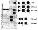
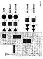
- FIG. 4illustrates a handset using a quadriplexer embodiment of the present invention according to FIG. 2 .
- each filter section ( 16 1 , 16 2 )is a duplexer.
- the first duplexer ( 16 1 )passes the receiving and transmitting frequencies of the PCS Band.
- the PCS Band reception pathincludes a low noise amplifier ( 18 1 ), band pass filter ( 20 1 ), and a mixer ( 22 1 ).
- the PCS band transmission pathincludes a band pass filter ( 20 2 ) and a power amplifier ( 24 1 ).
- the second duplexer ( 16 2 )passes the receiving and transmitting frequencies of the Cell Band.
- the Cell Band reception pathincludes a low noise amplifier ( 18 2 ), band pass filter ( 20 3 ), and a mixer ( 22 2 ).
- the Cell band transmission pathincludes a band pass filter ( 20 4 ) and a power amplifier ( 24 2 ).
- FIG. 5illustrates the filter response of the quadriplexer shown in FIG. 4 .
- FIG. 6illustrates another functional block diagram according to the present invention.
- the antenna terminal ( 12 )is connected to the first and second frequency phase shifters ( 14 1 , 14 2 , . . . 14 N ).
- Each frequency phase shifter ( 14 1 , 14 2 , . . . 14 N )connects to a filter section ( 16 1 , 16 2 , . . . 16 N ).
- An additional filter section ( 16 N+1 )connects to the first frequency phase shifter output.
- An optional inductor ( 30 )connects between the antenna terminal ( 12 ) and ground.
- the frequency phase shiftersare optional.
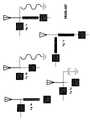
- FIGS. 7 a–fillustrates handsets using triplexer embodiments of the present invention according to FIG. 6 .
- each of the three filter sectionsis a bandpass filter.
- FIG. 8illustrates a handset using a quadriplexer embodiment of the present invention according to FIG. 6 .
- the modular frequency division filter ( 10 )includes three filter sections.
- An optional frequency phase shifter ( 14 3 )connects between the first and third filter sections.
- the first filter section ( 16 1 )is a duplexer.
- the first duplexer ( 16 1 )passes the receiving and transmitting frequencies of the PCS Band.
- the PCS Band reception pathincludes a low noise amplifier ( 18 1 ), a band pass filter ( 20 1 ), and a mixer ( 22 1 ).
- the PCS band transmission pathincludes a band pass filter ( 20 2 ) and a power amplifier ( 24 1 ).
- the second filter section ( 16 2 )is band pass filter that passes the ISMa band.
- the ISMa band transmission pathincludes a low noise amplifier ( 18 3 ), a band pass filter ( 20 5 ), and a mixer ( 20 3 ).
- the third filter section ( 16 3 )is band pass filter that passes the GPS band.
- the GPS band transmission pathincludes a low noise amplifier ( 18 4 ), a band pass filter ( 20 6 ), and a mixer ( 22 4 ). Two duplexers are used because the PCS and Cellular Bands are separated by at least 50% of the bandwidth.
- FIGS. 9 a and 9 billustrates a handset using quintplexer embodiments of the present invention according to FIG. 6 .
- the modular frequency division filter ( 10 ) shown in FIG. 8 aincludes 3 filter sections.
- the first filter sectionis a duplexer ( 16 1 ) passes the receiving and transmitting frequencies of the PCS Band.
- the PCS Band reception pathincludes a low noise amplifier ( 18 1 ), band pass filter ( 20 1 ), and a mixer ( 22 1 ).
- the PCS band transmission pathincludes a band pass filter ( 20 2 ) and a power amplifier ( 24 1 ).
- the second filter sectionis a duplexer ( 16 2 ) passes the receiving and transmitting frequencies of the Cell Band.
- the Cell Band reception pathincludes a low noise amplifier ( 18 2 ), band pass filter ( 20 3 ), and a mixer ( 22 2 ).
- the Cell band transmission pathincludes a band pass filter ( 20 4 ) and a power amplifier ( 24 2 ).
- the GPS band transmission pathincludes a low noise amplifier ( 18 4 ), a band pass filter ( 20 6 ), and a mixer ( 22 4 ).
- a shunt inductor 30is used in place of the second frequency phase shifter 14 2 .
- duplexersare used because the PCS and Cellular Bands are separated by at least 50% of the bandwidth.
- a band pass filteris used to separate the GPS frequency because it is within 10–50% of the PCS band.
- FIG. 10illustrates the filter response of a quintplexer as shown in the present invention.
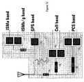
- FIG. 11illustrates a hexplexer embodiment of the present invention according to FIG. 6 .
- the modular frequency division filter ( 10 )includes 4 filter sections.
- the first filter sectionis a duplexer ( 16 1 ) passes the receiving and transmitting frequencies of the PCS Band.
- the second filter sectionis a duplexer ( 16 2 ) passes the receiving and transmitting frequencies of the Cell Band.
- the third filter section ( 16 4 )is band pass filter that passes the GPS band.
- the fourth filter section ( 16 5 )is band pass filter that passes the ISMb/g band.
- the modular frequency division filter ( 10 )includes 3 filter sections.
- the first filter sectionis a duplexer ( 16 1 ) that passes the receiving and transmitting frequencies of the PCS Band.
- the second filter sectionis a duplexer ( 16 2 ) that passes the receiving and transmitting frequencies of the Cell Band.
- the third filter sectionis a triplexer ( 16 .sub. 6 ) that passes the GPS, ISMa, ISMb/g bands.
- the triplexeris of the form shown in FIG. 6 .
Landscapes
- Engineering & Computer Science (AREA)
- Computer Networks & Wireless Communication (AREA)
- Signal Processing (AREA)
- Transceivers (AREA)
- Surface Acoustic Wave Elements And Circuit Networks Thereof (AREA)
Abstract
Description
| TABLE 1 | ||
| Standard | Use | Frequencies |
| Cellular Band (US) | Cellular Phone | 824 to 849 MHz Transmit |
| voice and data | 869 to 894 MHz Receive | |
| EGSM (non-US) | Cellular Phone | 880 to 915 MHz Transmit |
| voice and data | 925 to 960 MHz Receive | |
| GPS (global) | Location | 1575.42 MHz (L1) & |
| service | 1227.60 MHz (L2) | |
| DCS (non-US) | Cellular Phone | 1710 to 1785 MHz Transmit |
| voice and data | 1805 to 1880 MHz Receive | |
| PCS (US) | Cellular Phone | 1850 to 1910 MHz Transmit |
| voice and data | 930 to 1990 MHz Receive | |
| UMTS (non-US) | Cellular Phone | 1920 to 1980 MHz Transmit |
| voice and data | 2110 to 2170 MHz Receive | |
| ISM (worldwide) | Fixed data links, | Portions of 902 to 928 MHz, |
| with transmit and | 2400 to 2500 MHz (ISM b/g), | |
| receive at the | & 5000 to 6000 MHz (ISM a) | |
| same frequencies. | ||
Claims (12)
Priority Applications (1)
| Application Number | Priority Date | Filing Date | Title |
|---|---|---|---|
| US10/899,556US7126440B2 (en) | 2004-07-26 | 2004-07-26 | Modular frequency division filter |
Applications Claiming Priority (1)
| Application Number | Priority Date | Filing Date | Title |
|---|---|---|---|
| US10/899,556US7126440B2 (en) | 2004-07-26 | 2004-07-26 | Modular frequency division filter |
Publications (2)
| Publication Number | Publication Date |
|---|---|
| US20060017522A1 US20060017522A1 (en) | 2006-01-26 |
| US7126440B2true US7126440B2 (en) | 2006-10-24 |
Family
ID=35656508
Family Applications (1)
| Application Number | Title | Priority Date | Filing Date |
|---|---|---|---|
| US10/899,556Expired - LifetimeUS7126440B2 (en) | 2004-07-26 | 2004-07-26 | Modular frequency division filter |
Country Status (1)
| Country | Link |
|---|---|
| US (1) | US7126440B2 (en) |
Cited By (20)
| Publication number | Priority date | Publication date | Assignee | Title |
|---|---|---|---|---|
| US20060057987A1 (en)* | 2004-09-14 | 2006-03-16 | Nokia Corporation | Terminal and associated transducer assembly and method for selectively transducing in at least two frequency bands |
| US20060091975A1 (en)* | 2003-02-10 | 2006-05-04 | Epcos A G | Front-end circuit comprising thin-film resonators |
| US20060267707A1 (en)* | 2005-05-31 | 2006-11-30 | Ching-Wen Tang | Multilayer chip-type triplexer |
| US20060268811A1 (en)* | 2005-05-27 | 2006-11-30 | Tdk Corporation | Triplexer circuit |
| US20070080756A1 (en)* | 2005-10-07 | 2007-04-12 | Infineon Technologies Ag | BAW duplexer without phase shifter |
| US20070279149A1 (en)* | 2006-06-02 | 2007-12-06 | Ela Medical S.A.S. | Rf telemetry for an active medical device such as an implant or programmer for an implant |
| US20080268796A1 (en)* | 2007-04-27 | 2008-10-30 | Ntt Docomo, Inc | Radio communication device and power supplying method for radio communication device |
| US20090017772A1 (en)* | 2005-04-15 | 2009-01-15 | Hitachi Metals, Ltd. | Multiband high-frequency circuit, multiband high-frequency circuit device and multiband communications apparatus comprising same |
| KR100901602B1 (en) | 2006-12-29 | 2009-06-08 | 엘지이노텍 주식회사 | Multiplexer |
| US20100188165A1 (en)* | 2007-07-13 | 2010-07-29 | Hiroyuki Nakamura | Antenna duplexer and communication apparatus employing the same |
| DE102010011649A1 (en) | 2010-03-17 | 2011-09-22 | Epcos Ag | Front-end circuit for a mobile communication device with improved impedance matching |
| WO2011113697A1 (en) | 2010-03-17 | 2011-09-22 | Epcos Ag | Front-end circuit with increased flexibility in arranging the circuit components |
| US20120274417A1 (en)* | 2010-01-13 | 2012-11-01 | Murata Manufacturing Co., Ltd. | Multiplexer |
| US20120306591A1 (en)* | 2011-06-01 | 2012-12-06 | Taiyo Yuden Co., Ltd. | Electronic circuit and electronic module |
| US20130147578A1 (en)* | 2010-10-18 | 2013-06-13 | Taiyo Yuden Co., Ltd. | Duplexer |
| US8509711B1 (en) | 2010-01-11 | 2013-08-13 | L-3 Communications Corp. | Wireless terminals, systems, and methods using interlaced diplexers |
| US20160359506A1 (en)* | 2013-12-11 | 2016-12-08 | Epcos Ag | Front end circuit and method of operating a front end circuit |
| US9762208B2 (en) | 2015-09-30 | 2017-09-12 | Avago Technologies General Ip (Singapore) Pte. Ltd. | Very wide bandwidth composite bandpass filter with steep roll-off |
| US9893713B2 (en) | 2015-09-30 | 2018-02-13 | Avago Technologies General Ip (Singapore) Pte. Ltd. | Wide bandwidth muliplexer based on LC and acoustic resonator circuits for performing carrier aggregation |
| DE102015122185B4 (en) | 2014-12-23 | 2023-11-30 | Avago Technologies International Sales Pte. Limited | Multiplexer device having first and second filter devices connected to a common terminal |
Families Citing this family (4)
| Publication number | Priority date | Publication date | Assignee | Title |
|---|---|---|---|---|
| JP4710977B2 (en)* | 2006-12-19 | 2011-06-29 | 日立金属株式会社 | High frequency circuit, high frequency component, and communication device |
| DE102008052222B4 (en)* | 2008-10-17 | 2019-01-10 | Snaptrack, Inc. | Antenna duplexer with high GPS suppression |
| KR20150142201A (en)* | 2014-06-11 | 2015-12-22 | 엘지이노텍 주식회사 | Rf module |
| US10447241B2 (en)* | 2015-06-30 | 2019-10-15 | Murata Manufacturing Co., Ltd. | Wave separator |
Citations (12)
| Publication number | Priority date | Publication date | Assignee | Title |
|---|---|---|---|---|
| US5386203A (en)* | 1992-12-16 | 1995-01-31 | Murata Manufacturing Co., Ltd. | Antenna coupler |
| US5652599A (en)* | 1995-09-11 | 1997-07-29 | Qualcomm Incorporated | Dual-band antenna system |
| US5815804A (en)* | 1997-04-17 | 1998-09-29 | Motorola | Dual-band filter network |
| US6249687B1 (en)* | 1998-05-19 | 2001-06-19 | Siemens Aktiengesellschaft | Dual mode mobile phone using a multiplex type filter |
| US6662021B2 (en)* | 2001-10-13 | 2003-12-09 | Samsung Electronics Co., Ltd. | Mobile communication system having multi-band antenna |
| US6694129B2 (en)* | 2001-01-12 | 2004-02-17 | Qualcomm, Incorporated | Direct conversion digital domain control |
| US6724278B1 (en)* | 1999-01-19 | 2004-04-20 | Roke Manor Research Limited | Duplex filtering |
| US6759924B2 (en)* | 2000-06-08 | 2004-07-06 | Matsushita Electric Industrial Co., Ltd. | Multi-frequency antenna duplexer |
| US6845231B2 (en)* | 2003-03-24 | 2005-01-18 | Agilent Technologies, Inc. | Method facilitating inter-mode handoff |
| US6911708B2 (en)* | 2003-02-21 | 2005-06-28 | Lg Electronics Inc. | Duplexer filter having film bulk acoustic resonator and semiconductor package thereof |
| US6980067B2 (en)* | 2003-04-16 | 2005-12-27 | Kyocera Wireless Corp. | Triplexer systems and methods for use in wireless communications device |
| US6995630B2 (en)* | 2001-10-24 | 2006-02-07 | Matsushita Electric Industrial Co., Ltd. | High-frequency compound switch module and communication terminal using it |
- 2004
- 2004-07-26USUS10/899,556patent/US7126440B2/ennot_activeExpired - Lifetime
Patent Citations (12)
| Publication number | Priority date | Publication date | Assignee | Title |
|---|---|---|---|---|
| US5386203A (en)* | 1992-12-16 | 1995-01-31 | Murata Manufacturing Co., Ltd. | Antenna coupler |
| US5652599A (en)* | 1995-09-11 | 1997-07-29 | Qualcomm Incorporated | Dual-band antenna system |
| US5815804A (en)* | 1997-04-17 | 1998-09-29 | Motorola | Dual-band filter network |
| US6249687B1 (en)* | 1998-05-19 | 2001-06-19 | Siemens Aktiengesellschaft | Dual mode mobile phone using a multiplex type filter |
| US6724278B1 (en)* | 1999-01-19 | 2004-04-20 | Roke Manor Research Limited | Duplex filtering |
| US6759924B2 (en)* | 2000-06-08 | 2004-07-06 | Matsushita Electric Industrial Co., Ltd. | Multi-frequency antenna duplexer |
| US6694129B2 (en)* | 2001-01-12 | 2004-02-17 | Qualcomm, Incorporated | Direct conversion digital domain control |
| US6662021B2 (en)* | 2001-10-13 | 2003-12-09 | Samsung Electronics Co., Ltd. | Mobile communication system having multi-band antenna |
| US6995630B2 (en)* | 2001-10-24 | 2006-02-07 | Matsushita Electric Industrial Co., Ltd. | High-frequency compound switch module and communication terminal using it |
| US6911708B2 (en)* | 2003-02-21 | 2005-06-28 | Lg Electronics Inc. | Duplexer filter having film bulk acoustic resonator and semiconductor package thereof |
| US6845231B2 (en)* | 2003-03-24 | 2005-01-18 | Agilent Technologies, Inc. | Method facilitating inter-mode handoff |
| US6980067B2 (en)* | 2003-04-16 | 2005-12-27 | Kyocera Wireless Corp. | Triplexer systems and methods for use in wireless communications device |
Cited By (38)
| Publication number | Priority date | Publication date | Assignee | Title |
|---|---|---|---|---|
| US20060091975A1 (en)* | 2003-02-10 | 2006-05-04 | Epcos A G | Front-end circuit comprising thin-film resonators |
| US7469131B2 (en)* | 2004-09-14 | 2008-12-23 | Nokia Corporation | Terminal and associated transducer assembly and method for selectively transducing in at least two frequency bands |
| US20060057987A1 (en)* | 2004-09-14 | 2006-03-16 | Nokia Corporation | Terminal and associated transducer assembly and method for selectively transducing in at least two frequency bands |
| US7831230B2 (en) | 2004-09-14 | 2010-11-09 | Nokia Corporation | Terminal and associated transducer assembly and method for selectively transducing in at least two frequency bands |
| US20090111407A1 (en)* | 2004-09-14 | 2009-04-30 | Nokia Corporation | Terminal and Associated Transducer Assembly and Method for Selectively Transducing in at Least Two Frequency Bands |
| US20110096705A1 (en)* | 2005-04-15 | 2011-04-28 | Hitachi Metals, Ltd. | Multiband high-frequency circuit, multiband high-frequency circuit device and multiband communications apparatus comprising same |
| US8315577B2 (en) | 2005-04-15 | 2012-11-20 | Hitachi Metals, Ltd. | Multiband high-frequency circuit, multiband high-frequency circuit device and multiband communications apparatus comprising same |
| US20090017772A1 (en)* | 2005-04-15 | 2009-01-15 | Hitachi Metals, Ltd. | Multiband high-frequency circuit, multiband high-frequency circuit device and multiband communications apparatus comprising same |
| US7885613B2 (en)* | 2005-04-15 | 2011-02-08 | Hitachi Metals, Ltd. | Multiband high-frequency circuit, multiband high-frequency circuit device and multiband communications apparatus comprising same |
| US7495528B2 (en)* | 2005-05-27 | 2009-02-24 | Tdk Corporation | Triplexer circuit |
| US20060268811A1 (en)* | 2005-05-27 | 2006-11-30 | Tdk Corporation | Triplexer circuit |
| US20060267707A1 (en)* | 2005-05-31 | 2006-11-30 | Ching-Wen Tang | Multilayer chip-type triplexer |
| US7397324B2 (en)* | 2005-05-31 | 2008-07-08 | Industrial Technology Research Institute | Multilayer chip-type triplexer |
| US20070080756A1 (en)* | 2005-10-07 | 2007-04-12 | Infineon Technologies Ag | BAW duplexer without phase shifter |
| US7339445B2 (en)* | 2005-10-07 | 2008-03-04 | Infineon Technologies Ag | BAW duplexer without phase shifter |
| US20070279149A1 (en)* | 2006-06-02 | 2007-12-06 | Ela Medical S.A.S. | Rf telemetry for an active medical device such as an implant or programmer for an implant |
| US7663451B2 (en)* | 2006-06-02 | 2010-02-16 | Ela Medical S.A.S. | RF telemetry for an active medical device such as an implant or programmer for an implant |
| KR100901602B1 (en) | 2006-12-29 | 2009-06-08 | 엘지이노텍 주식회사 | Multiplexer |
| US8073407B2 (en)* | 2007-04-27 | 2011-12-06 | Ntt Docomo, Inc. | Radio communication device and power supplying method for radio communication device |
| US20080268796A1 (en)* | 2007-04-27 | 2008-10-30 | Ntt Docomo, Inc | Radio communication device and power supplying method for radio communication device |
| US8531252B2 (en)* | 2007-07-13 | 2013-09-10 | Panasonic Corporation | Antenna duplexer and communication apparatus employing the same |
| US20100188165A1 (en)* | 2007-07-13 | 2010-07-29 | Hiroyuki Nakamura | Antenna duplexer and communication apparatus employing the same |
| US8509711B1 (en) | 2010-01-11 | 2013-08-13 | L-3 Communications Corp. | Wireless terminals, systems, and methods using interlaced diplexers |
| US20120274417A1 (en)* | 2010-01-13 | 2012-11-01 | Murata Manufacturing Co., Ltd. | Multiplexer |
| WO2011113664A1 (en) | 2010-03-17 | 2011-09-22 | Epcos Ag | Front-end circuit for a mobile communications device, with improved impedance matching |
| WO2011113697A1 (en) | 2010-03-17 | 2011-09-22 | Epcos Ag | Front-end circuit with increased flexibility in arranging the circuit components |
| DE102010011651A1 (en) | 2010-03-17 | 2012-01-19 | Epcos Ag | Front-end circuit with increased flexibility in the arrangement of the circuit components |
| DE102010011649B4 (en) | 2010-03-17 | 2019-01-24 | Snaptrack, Inc. | Front-end circuit for a mobile communication device with improved impedance matching |
| DE102010011649A1 (en) | 2010-03-17 | 2011-09-22 | Epcos Ag | Front-end circuit for a mobile communication device with improved impedance matching |
| US20130147578A1 (en)* | 2010-10-18 | 2013-06-13 | Taiyo Yuden Co., Ltd. | Duplexer |
| US9203377B2 (en)* | 2010-10-18 | 2015-12-01 | Taiyo Yuden Co., Ltd. | Duplexer |
| US9071225B2 (en)* | 2011-06-01 | 2015-06-30 | Taiyo Yuden Co., Ltd. | Electronic circuit and electronic module |
| US20120306591A1 (en)* | 2011-06-01 | 2012-12-06 | Taiyo Yuden Co., Ltd. | Electronic circuit and electronic module |
| US20160359506A1 (en)* | 2013-12-11 | 2016-12-08 | Epcos Ag | Front end circuit and method of operating a front end circuit |
| US9948327B2 (en)* | 2013-12-11 | 2018-04-17 | Snaptrack, Inc. | Front end circuit and method of operating a front end circuit |
| DE102015122185B4 (en) | 2014-12-23 | 2023-11-30 | Avago Technologies International Sales Pte. Limited | Multiplexer device having first and second filter devices connected to a common terminal |
| US9762208B2 (en) | 2015-09-30 | 2017-09-12 | Avago Technologies General Ip (Singapore) Pte. Ltd. | Very wide bandwidth composite bandpass filter with steep roll-off |
| US9893713B2 (en) | 2015-09-30 | 2018-02-13 | Avago Technologies General Ip (Singapore) Pte. Ltd. | Wide bandwidth muliplexer based on LC and acoustic resonator circuits for performing carrier aggregation |
Also Published As
| Publication number | Publication date |
|---|---|
| US20060017522A1 (en) | 2006-01-26 |
Similar Documents
| Publication | Publication Date | Title |
|---|---|---|
| US7126440B2 (en) | Modular frequency division filter | |
| US7142884B2 (en) | Combined front-end circuit for wireless transmission systems | |
| US6990357B2 (en) | Front-end arrangements for multiband multimode communication engines | |
| US7155252B2 (en) | Mimo and diversity front-end arrangements for multiband multimode communication engines | |
| US7349717B2 (en) | Front-end circuit for wireless transmission systems | |
| US7398060B2 (en) | Method facilitating inter-mode handoff | |
| US7251499B2 (en) | Method and device for selecting between internal and external antennas | |
| KR101127022B1 (en) | High-frequency circuit and high-frequency component | |
| US10236925B2 (en) | High frequency front-end circuit and communication device | |
| US7583936B2 (en) | Circuit with reduced insertion loss and component comprising one such circuit | |
| JP6908000B2 (en) | High frequency circuit | |
| EP1673949B1 (en) | Multiband multimode communication engines | |
| CN101971511B (en) | Front-end circuit | |
| US20070183348A1 (en) | High-frequency circuit apparatus and communication apparatus using the same | |
| EP1614185A1 (en) | A frequency-selective device and method thereof for reception/transmission of communication signals in a wireless multi-band device | |
| US20090128254A1 (en) | High frequency electronic component | |
| US20190326944A1 (en) | Diplexer circuit | |
| US20160119017A1 (en) | Multiplexer device with multiple notch filters connected in parallel | |
| CN117897912A (en) | Radio frequency (RF) front end to support various simultaneous, synchronous, and asynchronous communication modes | |
| US20080139240A1 (en) | Communication device capable of operating in a plurality of communications systems | |
| US10715186B2 (en) | High frequency module and communication device | |
| US7162266B2 (en) | Multiple band handset architecture | |
| KR102430265B1 (en) | Radio frequency circuit and communication device | |
| US20090128253A1 (en) | High frequency electronic component | |
| JP2004320244A (en) | Multiband high-frequency signal transceiver module |
Legal Events
| Date | Code | Title | Description |
|---|---|---|---|
| AS | Assignment | Owner name:AGILENT TECHNOLOGIES, INC., COLORADO Free format text:ASSIGNMENT OF ASSIGNORS INTEREST;ASSIGNORS:BRDALEY, PAUL D.;FRANK, MICHAEL L.;YE, SHEN;REEL/FRAME:015228/0471 Effective date:20040726 | |
| AS | Assignment | Owner name:AVAGO TECHNOLOGIES GENERAL IP PTE. LTD.,SINGAPORE Free format text:ASSIGNMENT OF ASSIGNORS INTEREST;ASSIGNOR:AGILENT TECHNOLOGIES, INC.;REEL/FRAME:017206/0666 Effective date:20051201 Owner name:AVAGO TECHNOLOGIES GENERAL IP PTE. LTD., SINGAPORE Free format text:ASSIGNMENT OF ASSIGNORS INTEREST;ASSIGNOR:AGILENT TECHNOLOGIES, INC.;REEL/FRAME:017206/0666 Effective date:20051201 | |
| AS | Assignment | Owner name:CITICORP NORTH AMERICA, INC.,DELAWARE Free format text:SECURITY AGREEMENT;ASSIGNOR:AVAGO TECHNOLOGIES GENERAL IP (SINGAPORE) PTE. LTD.;REEL/FRAME:017207/0882 Effective date:20051201 Owner name:CITICORP NORTH AMERICA, INC., DELAWARE Free format text:SECURITY AGREEMENT;ASSIGNOR:AVAGO TECHNOLOGIES GENERAL IP (SINGAPORE) PTE. LTD.;REEL/FRAME:017207/0882 Effective date:20051201 | |
| AS | Assignment | Owner name:AVAGO TECHNOLOGIES WIRELESS IP (SINGAPORE) PTE. LT Free format text:ASSIGNMENT OF ASSIGNORS INTEREST;ASSIGNOR:AVAGO TECHNOLOGIES GENERAL IP (SINGAPORE) PTE. LTD;REEL/FRAME:017675/0434 Effective date:20060127 | |
| STCF | Information on status: patent grant | Free format text:PATENTED CASE | |
| FPAY | Fee payment | Year of fee payment:4 | |
| AS | Assignment | Owner name:AVAGO TECHNOLOGIES GENERAL IP (SINGAPORE) PTE. LTD Free format text:MERGER;ASSIGNOR:AVAGO TECHNOLOGIES WIRELESS IP (SINGAPORE) PTE. LTD.;REEL/FRAME:030369/0703 Effective date:20121030 | |
| AS | Assignment | Owner name:AVAGO TECHNOLOGIES GENERAL IP (SINGAPORE) PTE. LTD Free format text:RELEASE BY SECURED PARTY;ASSIGNOR:CITICORP NORTH AMERICA, INC.;REEL/FRAME:030422/0001 Effective date:20110331 | |
| FPAY | Fee payment | Year of fee payment:8 | |
| AS | Assignment | Owner name:DEUTSCHE BANK AG NEW YORK BRANCH, AS COLLATERAL AGENT, NEW YORK Free format text:PATENT SECURITY AGREEMENT;ASSIGNOR:AVAGO TECHNOLOGIES GENERAL IP (SINGAPORE) PTE. LTD.;REEL/FRAME:032851/0001 Effective date:20140506 Owner name:DEUTSCHE BANK AG NEW YORK BRANCH, AS COLLATERAL AG Free format text:PATENT SECURITY AGREEMENT;ASSIGNOR:AVAGO TECHNOLOGIES GENERAL IP (SINGAPORE) PTE. LTD.;REEL/FRAME:032851/0001 Effective date:20140506 | |
| AS | Assignment | Owner name:AVAGO TECHNOLOGIES GENERAL IP (SINGAPORE) PTE. LTD., SINGAPORE Free format text:TERMINATION AND RELEASE OF SECURITY INTEREST IN PATENT RIGHTS (RELEASES RF 032851-0001);ASSIGNOR:DEUTSCHE BANK AG NEW YORK BRANCH, AS COLLATERAL AGENT;REEL/FRAME:037689/0001 Effective date:20160201 Owner name:AVAGO TECHNOLOGIES GENERAL IP (SINGAPORE) PTE. LTD Free format text:TERMINATION AND RELEASE OF SECURITY INTEREST IN PATENT RIGHTS (RELEASES RF 032851-0001);ASSIGNOR:DEUTSCHE BANK AG NEW YORK BRANCH, AS COLLATERAL AGENT;REEL/FRAME:037689/0001 Effective date:20160201 | |
| AS | Assignment | Owner name:BANK OF AMERICA, N.A., AS COLLATERAL AGENT, NORTH CAROLINA Free format text:PATENT SECURITY AGREEMENT;ASSIGNOR:AVAGO TECHNOLOGIES GENERAL IP (SINGAPORE) PTE. LTD.;REEL/FRAME:037808/0001 Effective date:20160201 Owner name:BANK OF AMERICA, N.A., AS COLLATERAL AGENT, NORTH Free format text:PATENT SECURITY AGREEMENT;ASSIGNOR:AVAGO TECHNOLOGIES GENERAL IP (SINGAPORE) PTE. LTD.;REEL/FRAME:037808/0001 Effective date:20160201 | |
| AS | Assignment | Owner name:AVAGO TECHNOLOGIES GENERAL IP (SINGAPORE) PTE. LTD Free format text:CORRECTIVE ASSIGNMENT TO CORRECT THE ASSIGNEE NAME PREVIOUSLY RECORDED AT REEL: 017206 FRAME: 0666. ASSIGNOR(S) HEREBY CONFIRMS THE ASSIGNMENT;ASSIGNOR:AGILENT TECHNOLOGIES, INC.;REEL/FRAME:038632/0662 Effective date:20051201 | |
| AS | Assignment | Owner name:AVAGO TECHNOLOGIES GENERAL IP (SINGAPORE) PTE. LTD., SINGAPORE Free format text:TERMINATION AND RELEASE OF SECURITY INTEREST IN PATENTS;ASSIGNOR:BANK OF AMERICA, N.A., AS COLLATERAL AGENT;REEL/FRAME:041710/0001 Effective date:20170119 Owner name:AVAGO TECHNOLOGIES GENERAL IP (SINGAPORE) PTE. LTD Free format text:TERMINATION AND RELEASE OF SECURITY INTEREST IN PATENTS;ASSIGNOR:BANK OF AMERICA, N.A., AS COLLATERAL AGENT;REEL/FRAME:041710/0001 Effective date:20170119 | |
| MAFP | Maintenance fee payment | Free format text:PAYMENT OF MAINTENANCE FEE, 12TH YEAR, LARGE ENTITY (ORIGINAL EVENT CODE: M1553) Year of fee payment:12 | |
| AS | Assignment | Owner name:AVAGO TECHNOLOGIES INTERNATIONAL SALES PTE. LIMITE Free format text:MERGER;ASSIGNOR:AVAGO TECHNOLOGIES GENERAL IP (SINGAPORE) PTE. LTD.;REEL/FRAME:047196/0097 Effective date:20180509 | |
| AS | Assignment | Owner name:AVAGO TECHNOLOGIES INTERNATIONAL SALES PTE. LIMITE Free format text:CORRECTIVE ASSIGNMENT TO CORRECT THE EXECUTION DATE PREVIOUSLY RECORDED AT REEL: 047196 FRAME: 0097. ASSIGNOR(S) HEREBY CONFIRMS THE MERGER;ASSIGNOR:AVAGO TECHNOLOGIES GENERAL IP (SINGAPORE) PTE. LTD.;REEL/FRAME:048555/0510 Effective date:20180905 |