US7126381B1 - VPA interconnect circuit - Google Patents
VPA interconnect circuitDownload PDFInfo
- Publication number
- US7126381B1 US7126381B1US10/883,213US88321304AUS7126381B1US 7126381 B1US7126381 B1US 7126381B1US 88321304 AUS88321304 AUS 88321304AUS 7126381 B1US7126381 B1US 7126381B1
- Authority
- US
- United States
- Prior art keywords
- circuit
- interconnect
- interconnect circuit
- configurable
- input
- Prior art date
- Legal status (The legal status is an assumption and is not a legal conclusion. Google has not performed a legal analysis and makes no representation as to the accuracy of the status listed.)
- Expired - Fee Related
Links
- 238000013461designMethods0.000claimsdescription49
- 238000000034methodMethods0.000claimsdescription29
- 230000006870functionEffects0.000claimsdescription27
- 230000008569processEffects0.000description21
- 230000008859changeEffects0.000description10
- 238000012545processingMethods0.000description9
- 230000008901benefitEffects0.000description8
- 239000000872bufferSubstances0.000description6
- 238000004891communicationMethods0.000description4
- 230000001419dependent effectEffects0.000description3
- 230000000295complement effectEffects0.000description2
- 238000010586diagramMethods0.000description2
- 238000004519manufacturing processMethods0.000description2
- 230000003252repetitive effectEffects0.000description2
- 239000000758substrateSubstances0.000description2
- 230000007704transitionEffects0.000description2
- 238000013459approachMethods0.000description1
- 238000003491arrayMethods0.000description1
- 238000005516engineering processMethods0.000description1
- 230000007274generation of a signal involved in cell-cell signalingEffects0.000description1
- 238000002372labellingMethods0.000description1
- 230000005012migrationEffects0.000description1
- 238000013508migrationMethods0.000description1
- 230000002093peripheral effectEffects0.000description1
- 230000003068static effectEffects0.000description1
- 230000002123temporal effectEffects0.000description1
- 238000012546transferMethods0.000description1
- 230000009466transformationEffects0.000description1
- 230000001131transforming effectEffects0.000description1
- 230000001052transient effectEffects0.000description1
Images


Classifications
- H—ELECTRICITY
- H03—ELECTRONIC CIRCUITRY
- H03K—PULSE TECHNIQUE
- H03K19/00—Logic circuits, i.e. having at least two inputs acting on one output; Inverting circuits
- H03K19/02—Logic circuits, i.e. having at least two inputs acting on one output; Inverting circuits using specified components
- H03K19/173—Logic circuits, i.e. having at least two inputs acting on one output; Inverting circuits using specified components using elementary logic circuits as components
- H03K19/177—Logic circuits, i.e. having at least two inputs acting on one output; Inverting circuits using specified components using elementary logic circuits as components arranged in matrix form
- H03K19/17736—Structural details of routing resources
- H03K19/17744—Structural details of routing resources for input/output signals
- H—ELECTRICITY
- H03—ELECTRONIC CIRCUITRY
- H03K—PULSE TECHNIQUE
- H03K19/00—Logic circuits, i.e. having at least two inputs acting on one output; Inverting circuits
- H03K19/02—Logic circuits, i.e. having at least two inputs acting on one output; Inverting circuits using specified components
- H03K19/173—Logic circuits, i.e. having at least two inputs acting on one output; Inverting circuits using specified components using elementary logic circuits as components
- H03K19/177—Logic circuits, i.e. having at least two inputs acting on one output; Inverting circuits using specified components using elementary logic circuits as components arranged in matrix form
- H03K19/17748—Structural details of configuration resources
- H—ELECTRICITY
- H03—ELECTRONIC CIRCUITRY
- H03K—PULSE TECHNIQUE
- H03K19/00—Logic circuits, i.e. having at least two inputs acting on one output; Inverting circuits
- H03K19/02—Logic circuits, i.e. having at least two inputs acting on one output; Inverting circuits using specified components
- H03K19/173—Logic circuits, i.e. having at least two inputs acting on one output; Inverting circuits using specified components using elementary logic circuits as components
- H03K19/177—Logic circuits, i.e. having at least two inputs acting on one output; Inverting circuits using specified components using elementary logic circuits as components arranged in matrix form
- H03K19/1778—Structural details for adapting physical parameters
- H03K19/17796—Structural details for adapting physical parameters for physical disposition of blocks
Definitions
- the present inventionis directed towards VPA interconnect circuit.
- ICconfigurable integrated circuits
- FPGAfield programmable gate array
- An FPGAis a field programmable IC that has an internal array of logic circuits (also called logic blocks) that are connected together through numerous interconnect circuits (also called interconnects) and that are surrounded by input/output blocks.
- logic circuits and interconnect circuits of an FPGAare configurable.
- FIG. 1illustrates an example of a configurable logic circuit 100 .
- This logic circuitcan be configured to perform a number of different functions.
- the logic circuit 100receives a set of input data 105 and a set of configuration data 110 .
- the configuration data setis stored in a set of SRAM cells 115 .
- the configuration data setspecifies a particular function that this circuit has to perform on the input data set.
- the logic circuitperforms its function on the input data set, it provides the output of this function on a set of output lines 120 .
- the logic circuit 100is said to be configurable, as the configuration data set “configures” the logic circuit to perform a particular function, and this configuration data set can be modified by writing new data in the SRAM cells.
- FIG. 2illustrates an example of a configurable interconnect circuit 200 .
- This interconnect circuit 200connects a set of input data 205 to a set of output data 210 .
- This circuitreceives configuration data bits 215 that are stored in a set of SRAM cells 220 .
- the configuration bitsspecify how the interconnect circuit should connect the input data set to the output data set.
- the interconnect circuit 200is said to be configurable, as the configuration data set “configures” the interconnect circuit to use a particular connection scheme that connects the input data set to the output data set in a desired manner. Moreover, this configuration data set can be modified by writing new data in the SRAM cells.
- FIG. 3illustrates one example of the interconnect circuit 200 .
- This exampleis a 4-to-1 multiplexer 300 . Based on the configuration bits 215 that this multiplexer receives, the multiplexer 300 passes one of its four inputs 205 to its output 305 .
- FIG. 4illustrates a decoder 400 , which is another example of the interconnect circuit 200 . Based on the configuration bits 215 that this decoder receives, the decoder 400 passes its one input 405 to one or more of its outputs 210 , while having the outputs that are not connected to the input at a constant value (e.g., ground or VDD) or at a high impedance state.
- a constant valuee.g., ground or VDD
- FPGA'shave become popular as their configurable logic and interconnect circuits allow the FPGA's to be adaptively configured by system manufacturers for their particular applications.
- several configurable IC'shave been suggested that are capable of reconfiguration at runtime.
- IC'sthat can configure one or more times during one clock cycle. Consequently, most reconfigurable IC's take several cycles (e.g., tens, hundreds, or thousands of cycles) to reconfigure.
- VPGAvia programmable gate array
- U.S. Pat. No. 6,633,182(“the '182 patent”) discloses such configurable circuits.
- This patentdefines a VPGA as a configurable IC similar to an FPGA except that in a VPGA the programmability is provided by modifying the placement of vias rather than modifying data bits stored in a memory.
- the programmable interconnect pointis a single via, which replaces several transistors in an FPGA.
- Some embodiments of the inventionprovide a configurable integrated circuit (IC).
- the ICincludes an interconnect circuit having a first set of input terminals and a set of output terminals.
- the interconnect circuithas several connection schemes for connecting the first input set to the output set.
- the ICalso has a second set of input terminals for carrying a set of input signals, where at least several of the second set of input terminals overlap at least a plurality of the first set of input terminals.
- the ICfurther has a set of vias, where each via connects an input terminal in the first set with an input terminal in the second set.
- the interconnect circuitreceives a control signal and based in this control signal connects the first input terminal set to the output set by using a particular one of the connection schemes.
- FIG. 1illustrates an example of a configurable logic circuit.
- FIGS. 2–4illustrate several example of configurable interconnect circuits.
- FIG. 3illustrates one example of the interconnect circuit.
- FIGS. 5 and 6present two examples of interface circuits of IC's.
- FIG. 7illustrates an example of a sub-cycle signal generator.
- FIGS. 8–10present an example that illustrates how a larger, slower IC design can be implemented by a smaller, faster IC design.
- FIG. 11illustrates a sub-cycle configurable logic circuit of some embodiments of the invention.
- FIG. 12illustrates a complex logic circuit that is formed by four LUT's and an interconnect circuit.
- FIGS. 13–15illustrate three logic circuits that are three examples of the logic circuit of FIG. 11 .
- FIG. 16illustrates a logic circuit of another embodiment of the invention.
- FIG. 17illustrates a sub-cycle configurable interconnect circuit of some embodiments of the invention.
- FIGS. 18 and 19illustrate two examples of the interconnect circuit of FIG. 17 .
- FIG. 20illustrates the interconnect circuit of some embodiments of the invention.
- FIG. 21illustrates a VPA interconnect circuit of some embodiments of the invention.
- FIG. 22presents an example that illustrates the setting of vias in a VPA structure of FIG. 21 .
- FIG. 23illustrates another VPA interconnect circuit of some embodiments of the invention.
- FIG. 24conceptually illustrates a process that transforms a non-VPA configurable interconnect circuit into a VPA configurable interconnect circuit.
- FIG. 25illustrates an example of VPA configurable logic circuits.
- FIG. 26presents an example that illustrates the setting of vias in a VPA structure of a logic circuit.
- FIG. 27illustrates an example of the invention's VPA configurable logic circuit, which has phase bits as part of its VPA structure.
- FIG. 28illustrates an example of the setting of certain vias in the VPA of FIG. 27 .
- FIG. 29illustrates a portion of a configurable IC that has an array of logic circuits and interconnect circuits.
- FIG. 30illustrates a traditional microprocessor design.
- FIG. 31illustrates a configuration data pool for the configurable IC.
- FIG. 32illustrates an IC that has an array of non-traditional processing units and configurable interconnects.
- FIG. 33conceptually illustrates a more detailed example of a computing system that includes an IC of the invention.
- Some embodiments of the inventionare circuit elements that can be configured within “sub-cycles” of a “design cycle” or an “interface cycle” of an IC.
- An ICtypically has numerous clocks that are used to synchronize its operations.
- a clocktypically has a number of repetitive cycles.
- a clockalso has a period and a frequency (also called a rate).
- a clock's periodis the temporal duration of one of its repetitive cycles, while its frequency (or rate) is the inverse of its period. For example, a clock with a 10 ns period has a frequency of 100 MHz.
- the design clock rate (or frequency) of an IC or a portion of an ICis the clock rate for which the design of the IC or the portion of the IC has been specified.
- the design clock rateis defined as one over the duration of time between the fastest, stable (i.e., non-transient) change in a state of the design (e.g., the fastest change in an output of the design).
- the designis a Register Transfer Level (RTL) design
- the design clock ratecan be the clock rate for which the user specifies his or her design in a hardware definition language (HDL), such as VHDL or Verilog.
- HDLhardware definition language
- An interface rate of an ICis the rate at which the IC communicates with other circuitry. For instance, in some cases, an IC's interface rate is the rate that an interface circuit of the IC passes signals to and/or receives signals from circuits outside of the IC.
- An ICcan have one or more interface circuits, and these interface circuits can have the same or different interface rates.
- FIGS. 5 and 6present two examples of interface circuits.
- FIG. 5illustrates an IC 500 that has four one-directional interface circuits 505 , 510 , 515 , and 520 that operate at three different interface rates.
- FIG. 6illustrates an IC 600 that has two bi-directional interface circuits 605 and 610 that operate at the same interface rate of R 5 .
- An alternative term for an IC's interface rateis an input/output rate of the IC.
- An interface cycleis one over the interface rate, while a design cycle is one over the design rate.
- a sub-cycle of a design or interface cycleis a portion of the design or interface cycle.
- the term “primary cycle”refers to either a design cycle or an interface cycle.
- the term “primary clock”refers to either a design clock or an interface clock.
- a primary cycle's periodis broken into several sub-cycles of equal duration. For instance, a 10 ns cycle can be broken into 10 sub-cycles of 1 ns each.
- Some embodimentsuse sub-cycle signal generators that generate sub-cycle clocks and/or signals that have some relation with the primary clock but have faster rates than the primary clock.
- the sub-cycle clocks and/or signalsare derived from the primary clock.
- the sub-cycle clocks and/or signalshave rates that share a least common multiple with the rate of the primary clock.
- the sub-cycle clocks and/or signalsare aligned with the primary clock on at least some of their edge transitions. In some of these embodiments, each sub-cycle that falls within a particular cycle of the primary clock is referred to as a “phase.”
- FIG. 7illustrates an example of a sub-cycle signal generator 700 .
- This generatorreceives a primary clock 705 and generates a sub-cycle clock 710 that is four times faster than the received clock.
- the sub-cycle clockhas four phases ⁇ 0 , ⁇ 1 , ⁇ 2 , ⁇ 3 , during each cycle of the received clock.
- the sub-cycle signal generatorcan provide configurable circuit elements with its sub-cycle clock. In conjunction with this clock, or instead of this clock, the generator can provide configurable circuit elements with a signal whose value can change in each sub-cycle period.
- the sub-cycle signal generator 700generates a 2-bit phase signal, with four different values 00, 01, 10, and 11. These four values represent the four sub-cycles during each primary cycle. In this figure, these generated phase signals change in each sub-cycle and reset at the start of each period of the received clock.
- FIG. 7shows these phase signals as changing sequentially, these phase signals change in a non-sequential manner in some embodiments.
- the order of the phase signals in each period of the received clockcan differ, e.g., in one clock period the phase bits might appear as 00, 10, 11, 01, and in the next clock period the phase bits might appear as 11, 10, 01, 00.
- the sub-cycle signal generatorcan generate phase signals that have different ordering in different primary cycles by generating the phase bits based not only on the primary clock signal but also on programming signals that it receives. Such programming signals programmably direct the sub-cycle signal generator to generate different phase signals at different times.
- the sub-cycle signal generatorcan generate a phase signal that does not utilize all possible phase bit permutations or that utilizes one or more of the phase bit permutations more than once during a primary cycle.
- the sub-cycle signal generatormight use different encoding schemes (e.g., a Gray code encoding scheme, a one-hot encoding scheme, etc.) to generate its phase signals.
- a primary cyclemight be divided into more or fewer than four sub-cycles.
- a configurable logic circuitis a circuit that can be configured to perform a set of functions on a set of input data that it receives.
- the logic circuitreceives a set of configuration data that cause the logic circuit to perform a particular function within its set of functions on the input data set.
- the logic circuitthen outputs the result of this function as a set of output data.
- a logic circuitis sub-cycle configurable if the logic circuit can be configured one or more times within one primary cycle to perform more than one function. In other words, such a logic circuit can be reconfigured one or more times in a primary cycle.
- the sub-cycle configurable logic circuitscan be reconfigured to perform a new function within each sub-cycle of a primary cycle.
- a configurable interconnect circuitis a circuit that can configurably connect an input set to an output set in a variety of manners.
- An interconnect circuitreceives a configuration data set that causes the interconnect circuit to connect its input set to its output set in a particular manner.
- An interconnect circuitis sub-cycle configurable if it can be configured one or more times within one primary cycle to change the way it connects the input and output sets.
- a sub-cycle configurable interconnect circuitis a configurable interconnect circuit that can be reconfigured one or more times within a primary cycle.
- a sub-cycle configurable interconnect circuitcan be reconfigured within each sub-cycle of a primary cycle to change its connection scheme.
- FIGS. 8–10present an example that illustrates this benefit.
- FIG. 8illustrates a set of Boolean gates that compute two functions G 3 and P 3 based on a set of inputs A 0 , B 0 , A 1 , B 1 , A 2 , and B 2 .
- the set of Boolean gateshas to compute these two functions based on the received input set in one design cycle.
- one design cyclelasts 10 ns, as the design clock's frequency is 100 MHz.
- the technologycould easily operate at 400 MHz.
- each design cyclecan be broken down into 4 sub-cycles of 2.5 ns duration.
- FIG. 9illustrates the design 800 of FIG. 8 after its gates have been placed into four groups. These gates have been placed into four groups in order to break down the design 800 into four separate groups of gates that can be configured and executed in four sub-cycles by a smaller group of gates.
- the groupings illustrated in FIG. 9are designed to separate out the computation of different sets of gates while respecting the operational dependencies of other gates. For instance, gates 805 , 810 , and 815 are defined as a separate group from gates 820 , 825 , and 830 , as these two sets of gates have no operational dependencies (i.e., the output of the gates in one set is not dependent on the output of the gates in the other set).
- gates 835 , 840 , and 845are dependent on the outputs of the first two sets of gates. Hence, they are designated for configuration and execution during the third sub-cycle (i.e., during phase 3 ).
- the gate 850is dependent on the output of the first and third sets of gates, and thus it is designated for configuration and execution during the fourth sub-cycle (i.e., during phase 4 ).
- FIG. 10illustrates another representation of the design 800 of FIG. 8 .
- the schematic in FIG. 10illustrates four phases of operation.
- each gate in the design 800has been replaced by a sub-cycle configurable logic circuit 1005 , 1010 , or 1015 .
- only three logic circuits 1005 , 1010 , and 1015are used in FIG. 10 , as each of the gates in FIG. 8 can be implemented by one logic circuit, and the groupings illustrated in FIGS. 9 and 10 require at most 3 gates to be executing during any given phase. (In FIG.
- each logic circuit's operation during a particular phaseis identified by a superscript; so, for example, reference numbers 1005 1 , 1005 2 , and 1005 3 , respectively, identify the operation of the logic circuit 1005 during phases 1 , 2 , and 3 .
- the outputs of certain logic circuits in earlier phasesneed to be supplied to logic circuit operations in the later phases.
- state elementssuch as registers
- Such state elementscan be standalone circuit elements or can part of one or more sub-cycle configurable interconnect circuits (not shown) that are configured to connect the logic circuits in the desired manner.
- FIGS. 8–10illustrate that sub-cycle configurability allows a ten-gate design that operates at 100 MHz to be implemented by three sub-cycle configurable logic circuits and associated configurable interconnect circuits and state elements that operate at 400 MHz. It should be noted that even fewer than three logic circuits might be necessary if one logic gate can perform the operation of two or more gates that are executing during each phase illustrated in FIG. 9 .
- FIG. 11illustrates a sub-cycle configurable logic circuit 1100 of some embodiments of the invention.
- This logic circuitincludes a core logic circuit 1105 that can perform a variety of functions on a set of input data 1110 that it receives.
- the core logic circuit 105also receives a set of four configuration data bits 1115 through a switching circuit 1120 .
- the switching circuitreceives a larger set of sixteen configuration data bits 1125 that, in some embodiments, are stored in a set of memory cells 1130 (e.g., SRAM cells).
- This switching circuitis controlled by a phase ⁇ , which is generated by the above-described sub-cycle signal generator 700 .
- the generator 700in some embodiments generates a phase signal that is a 2-bit phase signal, which has a value that changes sequentially during each sub-cycle period and resets at the start of each primary cycle period.
- the sub-cycle signal generator 700generates a phase signal in other sequential or non-sequential manners with different ordering and/or encoding schemes.
- the switching circuitsupplies four configuration data bits 1115 to the logic circuit 1105 .
- the switching circuitis a set of four multiplexers 1140 .
- a multiplexeris any device that can select k-of-n signals, where k and n are any integer values. Multiplexers include pass transistors, sets of tri-stated buffers or transistors, or any device that can select k-of-n signals.
- each multiplexer 1140supplies one of four configuration bits that it receives to the logic circuit 1105 .
- switching circuits and sub-cycle generatorscan be used in other embodiments of the invention.
- the logic circuit 1105Based on the set of configuration data 1115 , the logic circuit 1105 performs on the input data set 1110 a particular function from the set of functions that it can perform. As the switching circuit 1120 can supply different configuration data sets 1115 to the logic circuit 1105 during different sub-cycles, the logic circuit 1105 can be configured to perform different functions on the input data set 1110 during different sub-cycles.
- the core logic circuit 1105has a set of n output lines 1145 , where n is an integer. This circuit provides the result of performing its configured function on the input data set 1110 along its output lines 1145 . These output lines provide the output of the overall logic circuit 1100 .
- the core logic circuit 1105is different in different embodiments of the invention.
- a logic circuit 1105is nothing more than a switching circuit that routes one or more of the input data bits to one or more of the output lines based on the value of the configuration data.
- the logic circuit 1105does not simply route a selection or a permutation of the input data set to the output data set but rather performs computations on the input data set to derive the output data set.
- logic circuitscan be complex logic circuit formed by multiple logic and interconnect circuits.
- FIG. 12illustrates a complex logic circuit 1200 that is formed by four LUT's 1205 and an interconnect circuit 1210 .
- One of ordinary skillwill realize that the illustration of the logic circuit 1200 is a simplification that does not show several circuit elements (e.g., fast-carry logic, etc.) that are commonly in complex logic circuits.
- FIGS. 13–15illustrate three logic circuits 1300 , 1400 , and 1500 , which are three examples of the logic circuit 1100 .
- the core logic circuits 1305 , 1405 , and 1505(which are one implementation of the core logic circuit 1105 of FIG. 11 ) are multiplexers.
- the logic circuits 1300 , 1400 , and 1500are all commutative with respect to the ordering of the input data set 1110 and the sub-cycle signals 1150 .
- the logic circuits 1300 , 1400 , and 1500all provides the same output for the same configuration data set 1125 , even though the ordering of the sub-cycle signals and the input data sets is different in these three examples.
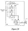
- FIG. 16illustrates another embodiment of the invention.
- This embodimentis a logic circuit 1600 that, like the logic circuit 1100 of FIG. 11 , can be reconfigured in each sub-cycle. However, unlike the logic circuit 1100 that can be configured in a non-sequential manner when the sub-cycle signal generator 700 provides a non-sequential signal, the logic circuit 1600 is only configured in a sequential manner.
- the logic circuit 1600has a core logic circuit 1105 and a sequential circuit 1610 .
- the sequential circuit 1610provides the core logic circuit 1105 with a configuration data set in each sub-cycle.
- four shift registers 1615form the sequential circuit 1610 . Each shift register stores one configuration data set.
- the shift registerspass their content (i.e., their configuration data bits) to each other in a counterclockwise manner as illustrated in FIG. 16 (i.e., 1615 a passes its content to 1615 b , 1615 b passes its content to 1615 c , 1615 c passes its content to 1615 d , and 1615 d passes its content to 1615 a ). Also, at the start of each sub-cycle period, the configuration data set in the register 1615 d is supplied to the logic circuit 1105 .
- the logic circuit 1105Based on the set of configuration data that it receives, the logic circuit 1105 selects, from the set of functions that it can perform, a particular function to perform on its input data set 1110 . As the sequential circuit 1610 can supply different configuration data sets to the logic circuit 1105 during different sub-cycles, the logic circuit 1105 can be configured to perform different functions on the input data set during different sub-cycles.
- the core logic circuit 1105provides its output (i.e., provides the result of performing the configured function on the input data set 1110 ) along its set of n output lines 1145 .
- FIG. 17illustrates a sub-cycle configurable interconnect circuit 1700 of some embodiments of the invention.
- This circuitconfigurably connects a set of input data terminals 1710 to a set of output data terminals 1715 based on a set of configuration data 1720 .
- This interconnect circuitincludes a core interconnect circuit 1705 that receives an input data set along the input data terminals 1710 and provides an output data set along the output data terminals 1715 .
- the core interconnect circuit 1705also receives the configuration data set 1720 through a switching circuit 1725 .
- the switching circuitreceives a larger set of configuration data bits 1730 that, in some embodiments, are stored in a set of memory cells 1130 (e.g., SRAM cells).
- This switching circuitis controlled by a phase ⁇ , which is generated by the sub-cycle signal generator 700 .
- the generator 700in some embodiments generates a phase signal that is a 2-bit phase signal, which has a value that changes sequentially during each sub-cycle period and resets at the start of each primary cycle period.
- the sub-cycle signal generator 700generates a phase signal in other sequential or non-sequential manners, with different ordering and/or encoding schemes.
- the switching circuit 1725supplies two of the eight configuration data bits 1730 as the configuration data set 1720 to the interconnect circuit 1705 .
- two multiplexers 1740form the switching circuit.
- each multiplexer 1740supplies one of four configuration bits that it receives to the interconnect circuit 1705 .
- a two-bit phase valueis written next to each configuration bit that is received by each switching multiplexer 1740 . These two-bit values identify the configuration bit associated with each pair of phase bits.
- switching circuits and/or sub-cycle signal generatorscan be used in other embodiments of the invention.
- the interconnect circuit 1705Based on the set of configuration data 1720 that it receives, the interconnect circuit 1705 connects the input terminal set 1710 to the output terminal set 1715 . As the switching circuit 1725 can supply different configuration data sets 1720 to the interconnect circuit 1705 during different sub-cycles, the interconnect circuit 1705 can differently connect the input terminal set 1710 to the output terminal set 1715 during different sub-cycles.
- the output terminal set 1715provides the output of the overall interconnect circuit 1700 in some embodiments.
- the core interconnect circuitis different in different embodiments of the invention. Any number of known interconnect circuits (also called interconnects or programmable interconnects) can be used in conjunction with the invention. Examples of such interconnect circuits include switch boxes, connection boxes, switching or routing matrices, full- or partial-cross bars, etc. Such interconnects can be implemented using a variety of known techniques and structures. Examples of interconnect circuits can be found Architecture and CAD for Deep-Submicron FPGAs, Betz, et al., ISBN 0792384601, 1999.
- the input terminal set 1710is a first set of lines
- the output terminal set 1715is a second set of lines.
- the second set of linesmight be collinear with the first set of lines, or might be in a direction that is offset (e.g., is at 90°) from the first set of lines.
- some of the second set of output linesmight be collinear with some of the first set of input lines, while other second-set lines might be at an angle with respect to some of the first-set lines.
- the interconnect circuit 1700is bi-directional. Specifically, in these embodiments, the interconnect circuit can use some or all of the terminal set 1710 to receive input data signals during some sub-cycles, while using the same terminals to supply output data signals during other sub-cycles. Similarly, in these embodiments, the interconnect circuit can use some or all of the terminal set 1715 to supply output data signals during some sub-cycles, while using the same terminals to receive input data signals during other sub-cycles.
- this circuit 1700is not sub-cycle configurable in other embodiments of the invention.
- this circuitreceives a control signal whenever a new configuration data set needs to be supplied to the core interconnect circuit 1705 .
- this control signalhas a frequency that is as fast as or faster than the primary clock rate. In other embodiments, this control signal's rate is slower than the primary clock rate. Alternatively, the control signal might not have any predictable rate.
- FIGS. 18 and 19illustrate two examples 1800 and 1900 of interconnect circuit 1700 .
- the core interconnect circuit 1805is a 4-to-1 multiplexer that connects during any given sub-cycle one of its four input lines 1710 to its one output line 1718 , based on the configuration data set 1720 that the multiplexer receives along its select lines.
- the multiplexer 1805can be configured to connect a different input line to its output line during each sub-cycle.
- the core interconnect circuit 1905is a 1-to-4 decoder. Based on the configuration data set 1720 that it receives along its configuration lines, this decoder connects during any given sub-cycle its input line 1710 to one or more of its output lines 1715 , while having the outputs that are not connected to the input set at a constant value (e.g., ground or VDD) or to a high impedance state. By having the ability to change the configuration data set 1720 during each sub-cycle, the decoder 1905 can be configured to connect a different set of output lines to its input line during each sub-cycle.
- a constant valuee.g., ground or VDD
- FIG. 20illustrates another embodiment of the invention.
- This embodimentis an interconnect circuit 2000 that, like the interconnect circuit 1700 of FIG. 17 , can be reconfigured in each sub-cycle.
- the interconnect circuit 2000can only be configured in a sequential manner.
- the interconnect circuit 2000has a core interconnect circuit 1705 and a sequential circuit 1610 .
- the sequential circuit 1610is identical to the sequential circuit 1610 of FIG. 16 .
- each shift register(1) stores one configuration data set during each sub-cycle and (2) passes its configuration data set to another shift register in a counterclockwise direction (that is shown in FIG. 20 ) at the start of each sub-cycle. Also, at the start of each sub-cycle period, the configuration data set in the register 1615 d is supplied to the interconnect circuit 1705 of the circuit 2000 .
- the interconnect circuit 1705then connects the input data set 1710 to the output data set 1715 based on the set of configuration data that this circuit receives.
- the sequential circuit 1610can supply different configuration data sets to the interconnect circuit 1705 during different sub-cycles
- the interconnect circuit 1705can be configured to connect the input and output data sets differently during different sub-cycles.
- Sections V and VIdescribe several interconnect and logic circuits with via programmable structures. This description refers to vias, potential vias, via programmable arrays, and VPGA's.
- a viais connection between two wires (e.g., two conductive lines) on two different wiring layers. Vias can be defined in an IC in a variety of ways (e.g., by defining a cut between two layers, by defining two electrical structures or devices on two different layers that can establish an electrical connection at runtime, etc.) If the wires are on two layers that have one or more intervening wiring layers, the via might be formed as a set of stacked vias, where each via in the stack is between two adjacent layers.
- a potential viais a site in an IC design for possibly defining a via.
- a via programmable arrayis a set of vias or potential vias for a particular configurable interconnect or logic circuit.
- a configurable VPA interconnect or logic circuitis an interconnect or logic circuit that has an associated VPA. In some of the embodiments described below, configuration data for a configurable interconnect or logic circuit is provided to the circuit by defining certain vias in the circuit's associated VPA.
- FIG. 21illustrates an interconnect circuit 2100 of some embodiments of the invention.
- the interconnect circuit 2100can be used in place of the interconnect circuit 1700 .
- the interconnect circuit 2100includes a VPA 2105 and a core interconnect circuit 2110 , which directly receives the phase signal 1150 .
- the VPA structure 2105is formed by two sets of lines that overlap. Typically, the two sets of lines appear on two different wiring layers of the IC, although these lines might appear on three or more layers in some embodiments.
- the first setis a set of input lines 2115
- the second setis a set of lines 2120 that are the inputs of the core logic circuit 2110 .
- each line in the first setoverlaps each line in the second set at a 90° angle. In other embodiments, each line in the first set might not overlap every line in the second set, and/or each overlap might not be at a 90° angle.
- the VPA structure 2105includes a potential via 2125 at each location where a line in the first set 2115 overlaps a line in the second set 2120 .
- certain vias in the array of potential viascan be set (i.e., defined) based on these values to complete the definition of the interconnect circuit 2100 .
- FIG. 22presents an example that illustrates the setting of vias in a VPA structure 2204 .
- this exampleillustrates how a non-VPA interconnect circuit 2250 can be transformed into a sub-cycle configurable VPA interconnect circuit 2200 .
- the non-VPA interconnect circuit 2250is similar to the above described interconnect circuit 1805 of FIG. 18 .
- the interconnect circuit 2250includes (1) a set of configuration storage elements 1130 , (2) a switching circuit 1725 that is formed by two 4-to-1 multiplexers 1740 , and (3) a core 4-to-1 multiplexer 1805 .
- the interconnect circuit 2200includes a 4-to-1 multiplexer 2202 and a VPA 2204 .
- the multiplexer 2202 and the VPA 2204together subsume all the functionalities of the switching multiplexers 1740 , configuration storage elements 1130 , and 4-to-1 multiplexer 1805 of the interconnect circuit 2250 , when the configuration data set 1730 has the values illustrated in FIG. 22 and the phase signal has values 00, 01, 10, and 11.
- a two-bit valueis written next to each bit that is received by a 4-to-1 multiplexer 1740 to identify the bit associated with each received pair of bits.
- a two-bit configuration valueis written next to each input line that is received by the core multiplexer 1805 to identify the input line associated with each possible configuration data set.
- the 4-to-1 multiplexer 1805connects one of its four input lines 1710 to its one output line 1715 , based on the configuration data set 1720 that the multiplexer receives along its select lines.
- the interconnect circuit 1805receives 01, 00, 10, and 11 as the configuration data set 1720 as the phase signal ⁇ cycles through the values 00, 01, 10, and 11.
- the phase signal ⁇does not need to proceed through the values 00, 01, 10, and 11 in any particular order or frequency. However, in some embodiments, this signal passes through these values in sequence and changes values in each sub-cycle.
- the interconnect circuit. 1805connects one of its input lines to its output line 1715 . Specifically, it connects its output line 1715 to (1) input I 2 when the phase is 00 (as this circuit receives the configuration data 01 during this phase), (2) input I 1 when the phase is 01 (as this circuit receives the configuration data 00 during this phase), (3) input I 3 when the phase is 10 (as this circuit receives the configuration data 10 during this phase), and (4) input I 4 when the phase is 11 (as this circuit receives the configuration data 11 during this phase).
- the vias that are defined in the VPA structure 2204are illustrated as black boxes. These defined vias allow the interconnect circuit 2200 to connect its input and output sets 2115 and 2225 in the same manner as the interconnect circuit 1805 in FIG. 22 , for the phase signal values 00, 01, 10, and 11. Specifically, like the output line 1715 of the interconnect circuit 1805 , the output line 2225 connects (1) to input line I 2 through via 2205 during phase 00 , (2) to input line I 1 through via 2210 during phase 01 , (3) to input line I 3 through via 2215 during phase 10 , and (4) to input line I 4 through via 2220 during phase 11 .
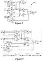
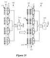
- FIG. 23presents an example that more clearly illustrates this transformation. This figure illustrates a VPA interconnect circuit 2300 and a non-VPA interconnect circuit 2305 that are functionally equivalent for a given phase signal and configuration data set.
- the non-VPA circuit 2305is similar to the non-VPA interconnect circuit 2250 illustrated in FIG. 22 , except that instead of the 4-to-1 multiplexer 1805 and two switching multiplexers 1740 , it uses an 8-to-1 multiplexer 2310 and three switching multiplexers 1740 .
- Each of the three switching multiplexers 1740is controlled by the two-bit phase signal ⁇ of the sub-cycle signal generator 700 . As before, in some embodiments, this phase signal has the values 00, 01, 10, and 11, although it can have a different set of phases in other embodiments as described above.
- the three switching multiplexersact as a switching circuit 2380 that outputs four 3-bit configuration values during the four phases.
- the 8-to-1 multiplexer 2310receives these 3-bit values 2325 on its select lines, and, based on each set of three values, connects one of its 8 inputs 2315 to its output 2320 . (A three-bit configuration value is written next to each input line of the 8-to-1 multiplexer to show the input bit associated with possible configuration data set.)
- the multiplexer 2310receives 001, 100, 110, and 011 as the configuration data set 2325 , while the phase signal ⁇ cycles through the values 00, 01, 10, and 11.
- the phase signal ⁇does not need to proceed through all the values or through the values 00, 01, 10, and 11 in any particular order or frequency. However, in some embodiments, this signal passes through these values in sequence and changes values in each sub-cycle.
- the interconnect circuit 2310connects one of its input lines 2315 to its output line 2320 . Specifically, it connects its output line 2320 to (1) input I 2 when the phase is 00 (as this circuit receives the configuration data 001 during this phase), (2) input I 5 when the phase is 01 (as this circuit receives the configuration data 100 during this phase), (3) input I 7 when the phase is 10 (as this circuit receives the configuration data 110 during this phase), and (4) input I 4 when the phase is 11 (as this circuit receives the configuration data 011 during this phase).
- the VPA interconnect circuit 2300 illustrated in FIG. 23is equivalent to the non-VPA interconnect circuit 2305 for the configuration data set and phase bits illustrated in this figure.
- the interconnect circuit 2300includes a 4-to-1 multiplexer circuit 2350 and a VPA 2355 , which together subsume all the functionalities of the switching multiplexers 1740 , configuration storage elements 1130 , and 8-to-1 multiplexer 2310 .
- the VPA structure 2355is formed by two sets of lines that overlap. Typically, the two sets of lines appear on two different wiring layers of the IC, although these lines might appear on three or more layers in some embodiments.
- the first set of overlapping linesis a set of eight input lines 2315
- the second set of overlapping linesis a set of four lines 2360 that are the inputs of the multiplexer 2350 .
- each line in the first setis at a 90° angle to each line in the second set. In other embodiments, each line in the first set might not overlap every line in the second set, and/or each overlap might not be a 90° angle.
- the VPA structure 2355includes a potential via 2365 at the overlap of each first-set line 2315 and each second-set line 2360 .
- FIG. 23identifies as black boxes the vias that need to be defined in the VPA structure 2355 , so that the interconnect circuit 2300 can connect its input and output sets 2315 and 2370 in the same manner as the interconnect circuit 2305 .
- the output line 2370 of the VPA interconnect circuit 2300connects to (1) input line I 2 through via 2372 during phase 00 , (2) input line I 5 through via 2374 during phase 01 , (3) input line I 7 through via 2376 during phase 10 , and (4) input line I 4 through via 2378 during phase 11 .
- This connection schemeis identical to the connection scheme of the interconnect circuit 2305 as described above.
- VPA interconnect circuits(such as circuits 2100 , 2200 , and 2300 ) have several advantages. For instance, they do not use costly SRAM cells to store configuration data. Instead, they encode such configuration data in their VPA's. VPA interconnects are also very efficient switching circuits, as they avoid much of the transistor switch logic of non-VPA interconnect circuit by using vias for their switching. In other words, non-VPA interconnect circuits supply configuration data through switching and storage circuits that have many transistors on the IC substrate. Such switching requires signals to traverse back and forth between the higher wiring layers and the IC substrate. VPA interconnects avoid these space- and time-consuming switching and storage circuits by defining vias that act as switches between two wiring layers. Hence, IC's that use VPA interconnects can be smaller and faster than traditional configurable IC's (e.g., FPGA's) while having cheaper masks than traditional ASIC's.
- traditional configurable IC'se.g., FPGA's
- FIG. 24conceptually illustrates a process 2400 that transforms a non-VPA configurable interconnect circuit into a VPA configurable interconnect circuit.
- the process 2400initially selects ( 2405 ) a sub-cycle configurable non-VPA interconnect circuit to transform to a VPA configurable interconnect circuit.
- the processselects non-VPA configurable interconnect circuit 2305 of FIG. 23 .
- the selected non-VPA interconnect circuittypically includes a core interconnect circuit (e.g., the interconnect circuit 2310 of FIG. 23 ) and a switching circuit (e.g., the switching circuit 2380 of FIG. 23 ) that supplies a configuration data set to the core interconnect circuit during each sub-cycle.
- the processspecifies a VPA interconnect circuit, which includes a core interconnect circuit and a VPA structure.
- the core interconnect circuit and the VPA structure of the VPA circuitare specified based on the core interconnect circuit of the selected non-VPA circuit, the number of sub-cycles, and the number of inputs. In the example illustrated in FIG. 23 , there are only four sub-cycles. During each of these four cycles, the core interconnect circuit 2310 relays the signal from one of its input lines 2315 to its one output line 2320 . Accordingly, for this example, the process specifies (at 2410 ) a core interconnect circuit that has at least one output line and at least four input lines.
- the VPA structure that is specified at 2410needs to be eight lines wide in the input signal direction. Accordingly, these minimum requirements result in the specification (at 2410 ) of the 4-to-1 multiplexer 2350 and VPA structure 2355 of FIG. 23 .
- the process 2400selects one of the sub-cycles and identifies the configuration data set that is received during this sub-cycle by the core interconnect circuit of the non-VPA circuit. For instance, in the example illustrated in FIG. 23 , the process could (at 2415 ) select the sub-cycle 00 and thus identify 001 as the configuration data set 2325 during this sub-cycle.
- the process 2400identifies the state of the core interconnect circuit during the selected sub-cycle for the identified configuration data set. For instance, in the example illustrated in FIG. 23 , the process determines (at 2420 ) that the core interconnect circuit 2310 relays the signal from the input line I 2 to its output line 2320 when it receives the configuration data set 001 during the sub-cycle 00 .
- the process 2400then defines (at 2425 ) one or more vias in the VPA structure that was specified at 2410 .
- the processdefines (at 2425 ) the via 2372 to allow the input I 2 to be communicatively coupled to the output line 2370 of the VPA circuit 2300 during the sub-cycle 00 .
- the processdetermines (at 2430 ) whether it has examined all of the sub-cycles. If not, the process (at 2415 ) selects another sub-cycle and identifies the configuration data set that is received during this sub-cycle by the core interconnect circuit of the non-VPA circuit. The process then transitions back to 2420 to identify the state of the core interconnect circuit during the selected sub-cycle for the identified configuration data set and then to 2425 to define a via in the VPA structure to account for this state. In this manner, the process 2400 loops through 2415 – 2430 until it defines a via in the VPA structure to account for all the possible states of the non-VPA interconnect circuit. For example, after identifying via 2372 in the example illustrated in FIG.
- the processloops through 2415 – 2430 three more times to define vias 2374 , 2376 , and 2378 to account for the connection of inputs I 5 , I 7 , and I 4 during sub-cycle phases 01 , 10 , and 11 .
- the process 2400determines (at 2430 ) that it has examined the non-VPA circuit's operation during all potential sub-cycles, the process 2400 terminates.
- the VPA structure 2505is formed by two sets of lines that overlap. Typically, the two sets of lines appear on two different wiring layers of the IC, although these lines might appear on three or more layers in some embodiments.
- the first setincludes two lines 2510 , one of which carries the 0 value, while the other carries the 1 value.
- the second set of linesis a set of lines 2515 that are the inputs of the multiplexers 1140 . As shown in FIG. 25 , each line in the first set overlaps each line in the second set at a 90° angle. In other embodiments, each line in the first set might not overlap every line in the second set, and/or each overlap might not be at a 90° angle.
- the VPA structure 2505includes a potential via 2520 at each location where a line in the first set 2510 and a line in the second set 2515 overlap.
- certain vias in the array of potential viascan be set (i.e., defined) to complete the definition of the logic circuit 2500 .
- FIG. 26presents an example that illustrates the setting of vias in a VPA structure of a logic circuit. Specifically, this example illustrates a particular configuration data set 1125 for the logic circuit 1100 . For this set of configuration data, FIG. 26 then illustrates sixteen black boxes in the VPA structure 2505 that represent the vias that are defined in this structure 2505 . These defined vias allow the logic circuit 2500 in FIG. 26 to perform the same function as the logic circuit 1100 in FIG. 26 .
- the invention's VPA configurable logic circuitshave phase bits as part of their VPA structure.
- FIG. 27illustrates an example of one such embodiment. Specifically, this figure illustrates a VPA configurable logic circuit 2700 that is functionally equivalent to the VPA configurable logic circuit 2500 of FIG. 25 and, hence, functionally equivalent to the non-VPA configurable logic circuit 1100 for a known configuration data set and phase signal.
- the structure of the logic circuit 2700has two differences from the logic circuit 2500 .
- the 4-to-1 switching multiplexers of logic circuit 2500have been replaced by 2-to-1 switching multiplexers 2740 that are controlled by only the phase bit ⁇ j.
- the other phase bits ⁇ i and its complement ⁇ i′are part of the VPA structure 2705 of the logic circuit 2700 .
- the VPA structure 2705is formed by two sets of overlapping lines 2710 and 2715 .
- the first set 2710includes four lines, two of which carry the 0 and 1 values, while the other two carry the phase bit ⁇ i and its complement ⁇ i′.
- the second set of lines 2715are inputs to the multiplexers 2740 .
- each line in the first setoverlaps each line in the second set at a 90° angle.
- each line in the first setmight not overlap every line in the second set, and/or each overlap might not be at a 90° angle.
- the IC 2900has two types of interconnect circuits 2910 a and 2910 b .
- Interconnect circuits 2910 aconnect interconnect circuits 2910 b and logic circuits 2905 (i.e., connect logic circuits 2905 to other logic circuits 2905 and interconnect circuits 2910 b , and connect interconnect circuits 2910 b to other interconnect circuits 2910 b and logic circuits 2905 ).
- Interconnect circuits 2910 bconnect interconnect circuits 2910 a to other interconnect circuits 2910 a.
- the IC 2900includes several signal generators 2902 that control the reconfiguration of the circuits 2905 and 2910 .
- the signal generatorsare sub-cycle signal generators that generate signals that enable some or all of the logic circuits to be sub-cycle configurable, as described above.
- the signal generatorsare not directly connected to all logic and interconnect circuits that they control. For instance, in some of these embodiments, the signals from these generators are routed to the appropriate configurable circuits through the configurable interconnect circuits 2910 .
- FIG. 29Although two signal generators are illustrated in FIG. 29 , other configurable IC's of the invention use more or fewer signal generators. For instance, the configurable IC's of some embodiments might only have one signal generator, or might not have a signal generator but instead might connect to a signal generator outside of the IC.
- the configurable IC 2900has a large number of logic and interconnect circuits (e.g., hundreds, thousands, etc. of such circuits).
- the configurable IC's of some embodimentsmight employ different architectures for arranging their logic and interconnect circuits. For instance, some embodiments might use a LAB architecture (a logic-array-block architecture), other symmetrical or asymmetrical architectures. Some embodiments might also use some of the architectural arrangements disclosed in United States patent application entitled “Configurable Integrated Circuit Architecture,” having Ser. No. 10/882,713, filed concurrently with this application. This Application is incorporated in the present application by reference.
- all logic circuits or large sets (e.g., hundreds) of logic circuits of the configurable IChave the same circuit structure (e.g., the same circuit elements and wiring between the circuit elements).
- the configurable ICwill have all of its interconnect circuits or large sets (e.g., hundreds) of its interconnect circuits have the same circuit structure. Re-using the same circuit structure for a large set of logic circuits or a large set of interconnect circuits simplifies the design and manufacturing of the configurable IC.
- some embodimentsmight use numerous different structures for their logic circuits and/or their interconnect circuits.
- the logic circuits of the configurable IC 2900are not traditional processing units that use traditional microprocessor designs (such as the Von Neumann design).
- FIG. 30illustrates a traditional microprocessor design.
- a typical microprocessor 3000often operates by repetitively performing fetch, decode, and execute operations.
- a microprocessortypically has an instruction processing pipeline that (1) fetches an encoded instruction from a program 3005 in memory 3010 , (2) decodes this instruction, (3) executes the decoded instruction, and (4) writes the result of the execution back to memory.
- the programis generated from a fixed set of encoded instructions upon which the design of the microprocessor is based.
- a microprocessor's instruction processing pipelineoften includes an instruction fetch unit 3015 for fetching instructions, a decoder 3020 for decoding the instructions, and one or more processing units 3025 for executing the decoded instruction.
- a microprocessormight have several instruction processing pipelines in order to perform several fetch-decode-execute cycles in parallel. In such cases, the microprocessor often has a separate decoder for each pipeline. As shown in FIG. 30 , a traditional microprocessor uses separate address and data buses 3030 and 3035 to identify locations in memory to read and write.
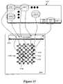
- FIG. 31illustrates a more detailed example of this. Specifically, this figure illustrates a configuration data pool 3105 for the configurable IC 2900 .
- This poolincludes N configuration data sets (CDS).
- This poolis stored in one or more memory/storage units, such as SRAMs, DRAMs, Flash, shift registers, disk, etc.
- an input/output circuitry 3120 of the configurable IC 2900routes different configuration data sets to different configurable logic and interconnect circuits of the IC 2900 .
- the I/O circuitry 3120can directly route numerous configuration data sets to numerous configurable circuits without first passing the configuration data through one or more decoders.
- a configuration data setmight be sent to numerous (e.g., 5) different configurable circuits (e.g., configurable logic circuits 3125 ).
- FIG. 31illustrates configurable circuit 3145 receiving configuration data sets 1 , 3 , and J through the I/O circuitry, while configurable circuit 3150 receives configuration data sets 3 , K, and N- 1 through the I/O circuitry.
- the configuration data setsare stored within each configurable circuit.
- a configurable circuitcan store multiple configuration data sets so that it can reconfigure quickly by changing to another configuration data set.
- some configurable circuitsstore only one configuration data set, while other configurable circuits store multiple such data sets.
- the logic circuitscan receive as input data the outputs of other logic circuits (i.e., the logic circuits can pass the result of their operations to other logic circuits without first writing these results in memory and having other logic circuits retrieve these results from memory).
- the logic circuit 3150might pass its output to the logic circuit 3160 through the interconnect circuit 3155 without first storing this output in a memory outside of the circuit array 3100 illustrated in this figure.
- the configurable IC 2900includes (1) an array of configurable logic circuits that do not use a traditional processor design, and (2) processor units outside of the array that use a traditional processor design.
- FIG. 32illustrates one such example. Specifically, this figure illustrates the IC 2900 as having an array 3220 of non-traditional processing units 2905 and configurable interconnects 2910 . The processing units are logic circuits that are configured and operated according to the approach illustrated in FIG. 31 .
- FIG. 32also shows the IC 2900 as having one on-chip processor 3205 that follows the traditional Von Neumann design that was described above in FIG. 30 . This on-chip processor 3205 can read and write instructions and/or data from an on-chip memory 3210 or an offchip memory 3215 .
- the processor 3205can communicate with the configurable array 3220 through memory 3210 and/or 3215 through on-chip bus 3225 and/or off-chip bus 3230 .
- the buses 3225 and 3230collectively represent all conductive paths that communicatively connect the devices or components illustrated in FIG. 32 .
- the bus 3310collectively represents all system, peripheral, and chipset interconnects (including bus and non-bus interconnect structures) that communicatively connect the numerous internal devices of the system 3300 .
- the bus 3310communicatively connects the IC 3305 with the read-only memory 3320 , the system memory 3315 , and the permanent storage device 3325 .
- the configuration data poolis stored in one or more of these memory units in some embodiments of the invention. Also, from these various memory units, the IC 3305 receives data for processing and configuration data for configuring the IC's configurable logic and/or interconnect circuits. When the IC 3305 has a processor, the IC also retrieves from the various memory units instructions to execute.
- the read-only-memory (ROM) 3320stores static data and/or instructions that are needed by the IC 3305 and other modules of the system 3300 .
- the storage device 3325is read-and-write memory device. This device is a non-volatile memory unit that stores instruction and/or data even when the system 3300 is off.
- the system memory 3315is a read-and-write memory device. However, unlike storage device 3325 , the system memory is a volatile read-and-write memory, such as a random access memory. The system memory stores some of the instructions and/or data that the IC needs at runtime.
- the bus 3310also connects to the input and output devices 3330 and 3335 .
- the input devicesenable the user to enter information into the system 3300 .
- the input devices 3330can include touch-sensitive screens, keys, buttons, keyboards, cursor-controllers, microphone, etc.
- the output devices 3335display the output of the system 3300 .
- bus 3310also couples system 3300 to other devices through a communication interface 3340 .
- Examples of the communication interfaceinclude network adapters that connect to a network of computers, or wired or wireless transceivers for communicating with other devices.
- network adaptersthat connect to a network of computers, or wired or wireless transceivers for communicating with other devices.
- wired or wireless transceiversfor communicating with other devices.
- any other system configurationmay also be used in conjunction with the invention, and these system configurations might have fewer or additional components.
- the logic and interconnect circuitscan reconfigure and execute multiple times within one design or interface cycle, as they are sub-cycle configurable. By configuring and executing these circuits on a sub-cycle basis, a smaller, faster IC can be specified. Such a smaller, faster IC can be used to implement the design of a larger, slower IC, at a fraction of the cost for manufacturing the larger IC.
- logic and interconnect circuitscan be reconfigured in a non-sequential manner. Rather, each of these circuits can be reconfigured to perform a number of operations in a number of arbitrary sequences. These circuits can be reconfigured in such a non-sequential manner because the sub-cycle signal generator 700 can generate a sub-cycle signal that has no particular pattern, which, in turn, allows these circuits to supply any desirable, arbitrary sequence of configuration data sets to their core interconnect or logic circuits.
- the signal generatorin some embodiments generates a sub-cycle signal that has a pattern that may or may not sequentially increment or decrement through all possible values of the signal.
- Such flexibility in the signal generation and the architecture of the configurable circuitsprovides tremendous gains in speed and size of the configurable IC.
- FIG. 29illustrates an IC with homogenous architectures
- the IC's of other embodimentsmight use heterogeneous architectures (e.g., SOC architectures) such as the one illustrated in FIG. 32 .
- bufferscan be placed between the multiplexers 1140 and circuit 1105 and/or after the circuit 1105 .
- Buffer circuitsare not logic or interconnect circuits. Buffer circuits can be used to achieve one or more objectives (e.g., maintain the signal strength, reduce noise, delay signal, etc.) for connections between circuits.
- Inverting buffer circuitsalso allow an IC design to reconfigure logic circuits less frequently and/or use fewer types of logic circuits.
- buffer circuitsare formed by one or more inverters (e.g., two or more inverters that are connected in series).
- the intermediate circuits between the logic and/or interconnect circuitscan be viewed as a part of the devices illustrated in these figures.
- the inverters that can be placed after the devices 1105 and 1140can be viewed as being part of these devices. Some embodiments use such inverters in order to allow an IC design to reconfigure logic circuits less frequently and/or use fewer types of logic circuits.
- FIGS. 5 and 6illustrate IC's with dedicated interface circuits
- IC's of some embodimentsdo not have dedicated interface circuits.
- the IC'shave circuits that are reconfigured into interface circuits periodically to receive or output signals.
- timing diagramsshow the sub-cycle phases as falling completely within a primary cycle
- the sub-cycle phasesmight be offset by some amount from their associated primary cycles.
- the inventionis not to be limited by the foregoing illustrative details, but rather is to be defined by the appended claims.
Landscapes
- Physics & Mathematics (AREA)
- Mathematical Physics (AREA)
- Engineering & Computer Science (AREA)
- Computer Hardware Design (AREA)
- Computing Systems (AREA)
- General Engineering & Computer Science (AREA)
- Computer Networks & Wireless Communication (AREA)
- Logic Circuits (AREA)
- Design And Manufacture Of Integrated Circuits (AREA)
Abstract
Description
Claims (19)
Priority Applications (2)
| Application Number | Priority Date | Filing Date | Title |
|---|---|---|---|
| US10/883,213US7126381B1 (en) | 2004-02-14 | 2004-06-30 | VPA interconnect circuit |
| US11/535,053US7564260B1 (en) | 2004-02-14 | 2006-09-25 | VPA interconnect circuit |
Applications Claiming Priority (2)
| Application Number | Priority Date | Filing Date | Title |
|---|---|---|---|
| US56074704P | 2004-02-14 | 2004-02-14 | |
| US10/883,213US7126381B1 (en) | 2004-02-14 | 2004-06-30 | VPA interconnect circuit |
Related Child Applications (1)
| Application Number | Title | Priority Date | Filing Date |
|---|---|---|---|
| US11/535,053ContinuationUS7564260B1 (en) | 2004-02-14 | 2006-09-25 | VPA interconnect circuit |
Publications (1)
| Publication Number | Publication Date |
|---|---|
| US7126381B1true US7126381B1 (en) | 2006-10-24 |
Family
ID=37110557
Family Applications (2)
| Application Number | Title | Priority Date | Filing Date |
|---|---|---|---|
| US10/883,213Expired - Fee RelatedUS7126381B1 (en) | 2004-02-14 | 2004-06-30 | VPA interconnect circuit |
| US11/535,053Expired - Fee RelatedUS7564260B1 (en) | 2004-02-14 | 2006-09-25 | VPA interconnect circuit |
Family Applications After (1)
| Application Number | Title | Priority Date | Filing Date |
|---|---|---|---|
| US11/535,053Expired - Fee RelatedUS7564260B1 (en) | 2004-02-14 | 2006-09-25 | VPA interconnect circuit |
Country Status (1)
| Country | Link |
|---|---|
| US (2) | US7126381B1 (en) |
Cited By (19)
| Publication number | Priority date | Publication date | Assignee | Title |
|---|---|---|---|---|
| US20060001445A1 (en)* | 2004-07-02 | 2006-01-05 | Tatung Co., Ltd. | Programmable logic block for designing an asynchronous circuit |
| US20060157739A1 (en)* | 2005-01-18 | 2006-07-20 | Nec Electronics Corporation | Semiconductor integrated circuit, layout method, layout apparatus and layout program |
| US20060206696A1 (en)* | 2005-03-14 | 2006-09-14 | Fujitsu Limited | Reconfigurable processor |
| US20070241771A1 (en)* | 2004-02-14 | 2007-10-18 | Herman Schmit | Configurable circuits, IC's, and systems |
| US20070241788A1 (en)* | 2004-06-30 | 2007-10-18 | Herman Schmit | VPA Logic Circuits |
| US20070241787A1 (en)* | 2004-06-30 | 2007-10-18 | Herman Schmit | Configurable Circuits, IC's, and Systems |
| US20070241776A1 (en)* | 2004-06-30 | 2007-10-18 | Herman Schmit | Configurable Logic Circuits with Commutative Properties |
| US7521959B2 (en) | 2007-03-20 | 2009-04-21 | Tabula, Inc. | Configurable IC having a routing fabric with storage elements |
| US7532032B2 (en) | 2004-02-14 | 2009-05-12 | Tabula, Inc. | Configurable circuits, IC's, and systems |
| US7564260B1 (en) | 2004-02-14 | 2009-07-21 | Tabula Inc. | VPA interconnect circuit |
| US20090219051A1 (en)* | 2006-04-19 | 2009-09-03 | Wei Zhang | Hybrid nanotube/cmos dynamically reconfigurable architecture and an integrated design optimization method and system therefor |
| US7616027B2 (en) | 2004-02-14 | 2009-11-10 | Tabula, Inc. | Configurable circuits, IC's and systems |
| US7622951B2 (en) | 2004-02-14 | 2009-11-24 | Tabula, Inc. | Via programmable gate array with offset direct connections |
| US7626419B1 (en) | 2005-11-11 | 2009-12-01 | Tabula, Inc. | Via programmable gate array with offset bit lines |
| US7667486B2 (en) | 2004-02-14 | 2010-02-23 | Tabula, Inc. | Non-sequentially configurable IC |
| WO2010033263A1 (en) | 2008-09-17 | 2010-03-25 | Tabula, Inc. | Controllable storage elements for an ic |
| US20130021058A1 (en)* | 2010-04-02 | 2013-01-24 | Tabula, Inc. | System and method for reducing reconfiguration power usage |
| US20150200671A1 (en)* | 2013-02-27 | 2015-07-16 | Tabula, Inc. | Implementation of related clocks |
| US10515171B2 (en)* | 2018-03-16 | 2019-12-24 | Kabushiki Kaisha Toshiba | Circuit description generation apparatus and circuit description generation method |
Families Citing this family (1)
| Publication number | Priority date | Publication date | Assignee | Title |
|---|---|---|---|---|
| US12265417B2 (en)* | 2021-09-22 | 2025-04-01 | Altera Corporation | Configurable clock macro circuits and methods |
Citations (64)
| Publication number | Priority date | Publication date | Assignee | Title |
|---|---|---|---|---|
| US4873459A (en) | 1986-09-19 | 1989-10-10 | Actel Corporation | Programmable interconnect architecture |
| US5349250A (en) | 1993-09-02 | 1994-09-20 | Xilinx, Inc. | Logic structure and circuit for fast carry |
| US5357153A (en) | 1993-01-28 | 1994-10-18 | Xilinx, Inc. | Macrocell with product-term cascade and improved flip flop utilization |
| US5365125A (en) | 1992-07-23 | 1994-11-15 | Xilinx, Inc. | Logic cell for field programmable gate array having optional internal feedback and optional cascade |
| US5521835A (en) | 1992-03-27 | 1996-05-28 | Xilinx, Inc. | Method for programming an FPLD using a library-based technology mapping algorithm |
| US5552721A (en) | 1995-06-05 | 1996-09-03 | International Business Machines Corporation | Method and system for enhanced drive in programmmable gate arrays |
| US5631578A (en) | 1995-06-02 | 1997-05-20 | International Business Machines Corporation | Programmable array interconnect network |
| US5646544A (en) | 1995-06-05 | 1997-07-08 | International Business Machines Corporation | System and method for dynamically reconfiguring a programmable gate array |
| US5659484A (en) | 1993-03-29 | 1997-08-19 | Xilinx, Inc. | Frequency driven layout and method for field programmable gate arrays |
| US5692147A (en) | 1995-06-07 | 1997-11-25 | International Business Machines Corporation | Memory mapping method and apparatus to fold sparsely populated structures into densely populated memory columns or rows by selectively transposing X and Y address portions, and programmable gate array applications thereof |
| US5719889A (en) | 1995-12-20 | 1998-02-17 | International Business Machines Corporation | Programmable parity checking and comparison circuit |
| US5732246A (en) | 1995-06-07 | 1998-03-24 | International Business Machines Corporation | Programmable array interconnect latch |
| US5737235A (en) | 1995-05-02 | 1998-04-07 | Xilinx Inc | FPGA with parallel and serial user interfaces |
| US5745734A (en) | 1995-09-29 | 1998-04-28 | International Business Machines Corporation | Method and system for programming a gate array using a compressed configuration bit stream |
| US5745422A (en) | 1996-11-12 | 1998-04-28 | International Business Machines Corporation | Cross-coupled bitline segments for generalized data propagation |
| US5764954A (en) | 1995-08-23 | 1998-06-09 | International Business Machines Corporation | Method and system for optimizing a critical path in a field programmable gate array configuration |
| US5777360A (en) | 1994-11-02 | 1998-07-07 | Lsi Logic Corporation | Hexagonal field programmable gate array architecture |
| US5802003A (en) | 1995-12-20 | 1998-09-01 | International Business Machines Corporation | System for implementing write, initialization, and reset in a memory array using a single cell write port |
| US5815372A (en)* | 1997-03-25 | 1998-09-29 | Intel Corporation | Packaging multiple dies on a ball grid array substrate |
| US5815726A (en)* | 1994-11-04 | 1998-09-29 | Altera Corporation | Coarse-grained look-up table architecture |
| US5889411A (en) | 1997-02-26 | 1999-03-30 | Xilinx, Inc. | FPGA having logic element carry chains capable of generating wide XOR functions |
| US5914616A (en) | 1997-02-26 | 1999-06-22 | Xilinx, Inc. | FPGA repeatable interconnect structure with hierarchical interconnect lines |
| US5914906A (en) | 1995-12-20 | 1999-06-22 | International Business Machines Corporation | Field programmable memory array |
| US5982655A (en) | 1998-09-29 | 1999-11-09 | Cisco Technology, Inc. | Method and apparatus for support of multiple memory types in a single memory socket architecture |
| US6002991A (en) | 1996-08-30 | 1999-12-14 | Xilinx, Inc. | Method and apparatus for measuring localized voltages on programmable integrated circuits |
| US6054873A (en) | 1996-12-05 | 2000-04-25 | International Business Machines Corporation | Interconnect structure between heterogeneous core regions in a programmable array |
| US6069490A (en) | 1997-12-02 | 2000-05-30 | Xilinx, Inc. | Routing architecture using a direct connect routing mesh |
| US6086631A (en) | 1998-04-08 | 2000-07-11 | Xilinx, Inc. | Post-placement residual overlap removal method for core-based PLD programming process |
| US6091263A (en) | 1997-12-12 | 2000-07-18 | Xilinx, Inc. | Rapidly reconfigurable FPGA having a multiple region architecture with reconfiguration caches useable as data RAM |
| US6107821A (en) | 1999-02-08 | 2000-08-22 | Xilinx, Inc. | On-chip logic analysis and method for using the same |
| US6110223A (en) | 1996-10-28 | 2000-08-29 | Altera Corporation | Graphic editor for block diagram level design of circuits |
| US6140839A (en) | 1998-05-13 | 2000-10-31 | Kaviani; Alireza S. | Computational field programmable architecture |
| US6150838A (en) | 1999-02-25 | 2000-11-21 | Xilinx, Inc. | FPGA configurable logic block with multi-purpose logic/memory circuit |
| US6175247B1 (en) | 1998-04-14 | 2001-01-16 | Lockheed Martin Corporation | Context switchable field programmable gate array with public-private addressable sharing of intermediate data |
| US6184707B1 (en)* | 1998-10-07 | 2001-02-06 | Altera Corporation | Look-up table based logic element with complete permutability of the inputs to the secondary signals |
| US6292019B1 (en) | 1999-05-07 | 2001-09-18 | Xilinx Inc. | Programmable logic device having configurable logic blocks with user-accessible input multiplexers |
| US20020008541A1 (en) | 1997-02-26 | 2002-01-24 | Xilinx, Inc. | Interconnect structure for a programmable logic device |
| US6381732B1 (en) | 1999-01-14 | 2002-04-30 | Xilinx, Inc. | FPGA customizable to accept selected macros |
| US20020125914A1 (en) | 2001-03-08 | 2002-09-12 | Lg Electronics Inc. | Glitch free clock multiplexer circuit and method thereof |
| US20020163357A1 (en) | 1993-08-03 | 2002-11-07 | Btr, Inc. | Architecture and interconnect scheme for programmable logic circuits |
| US6487709B1 (en) | 2000-02-09 | 2002-11-26 | Xilinx, Inc. | Run-time routing for programmable logic devices |
| US6490707B1 (en) | 2000-07-13 | 2002-12-03 | Xilinx, Inc. | Method for converting programmable logic devices into standard cell devices |
| US6515505B1 (en)* | 1995-12-26 | 2003-02-04 | Cypress Semiconductor Corp. | Functionality change by bond optioning decoding |
| US6515509B1 (en) | 2000-07-13 | 2003-02-04 | Xilinx, Inc. | Programmable logic device structures in standard cell devices |
| US6526559B2 (en) | 2001-04-13 | 2003-02-25 | Interface & Control Systems, Inc. | Method for creating circuit redundancy in programmable logic devices |
| US6529040B1 (en) | 2000-05-05 | 2003-03-04 | Xilinx, Inc. | FPGA lookup table with speed read decoder |
| US20030042931A1 (en) | 1993-08-03 | 2003-03-06 | Ting Benjamin S. | Architecture and interconnect scheme for programmable logic circuits |
| US6545501B1 (en) | 2001-12-10 | 2003-04-08 | International Business Machines Corporation | Method and system for use of a field programmable function within a standard cell chip for repair of logic circuits |
| US20030110430A1 (en) | 2001-12-10 | 2003-06-12 | International Business Machines Corporation | Method and system for use of a field programmable gate array (FPGA) function within an application specific integrated circuit (ASIC) to enable creation of a debugger client within the ASIC |
| US6593771B2 (en) | 2001-12-10 | 2003-07-15 | International Business Machines Corporation | Method and system for use of a field programmable interconnect within an ASIC for configuring the ASIC |
| US6601227B1 (en) | 2001-06-27 | 2003-07-29 | Xilinx, Inc. | Method for making large-scale ASIC using pre-engineered long distance routing structure |
| US6603330B1 (en) | 2000-10-26 | 2003-08-05 | Cypress Semiconductor Corporation | Configuring digital functions in a digital configurable macro architecture |
| US6629308B1 (en) | 2000-07-13 | 2003-09-30 | Xilinx, Inc. | Method for managing database models for reduced programmable logic device components |
| US6636070B1 (en) | 1997-10-16 | 2003-10-21 | Altera Corp | Driver circuitry for programmable logic devices with hierarchical interconnection resources |
| US6642744B2 (en) | 2000-03-10 | 2003-11-04 | Easic Corporation | Customizable and programmable cell array |
| US6667635B1 (en) | 2002-09-10 | 2003-12-23 | Xilinx, Inc. | FPGA lookup table with transmission gate structure for reliable low-voltage operation |
| US6668361B2 (en) | 2001-12-10 | 2003-12-23 | International Business Machines Corporation | Method and system for use of a field programmable function within a chip to enable configurable I/O signal timing characteristics |
| US6675309B1 (en) | 2000-07-13 | 2004-01-06 | Xilinx, Inc. | Method for controlling timing in reduced programmable logic devices |
| US6714041B1 (en) | 2002-08-30 | 2004-03-30 | Xilinx, Inc. | Programming on-the-fly (OTF) |
| US6806730B2 (en) | 2001-12-10 | 2004-10-19 | International Business Machines Corporation | Method and system for use of an embedded field programmable gate array interconnect for flexible I/O connectivity |
| US6831479B2 (en) | 2000-05-03 | 2004-12-14 | Marvell International Ltd. | Circuit for reducing pin count of a semiconductor chip and method for configuring the chip |
| US6838902B1 (en) | 2003-05-28 | 2005-01-04 | Actel Corporation | Synchronous first-in/first-out block memory for a field programmable gate array |
| US6992505B1 (en) | 2004-03-09 | 2006-01-31 | Xilinx, Inc. | Structures and methods of implementing a pass gate multiplexer with pseudo-differential input signals |
| US7030651B2 (en)* | 2003-12-04 | 2006-04-18 | Viciciv Technology | Programmable structured arrays |
Family Cites Families (52)
| Publication number | Priority date | Publication date | Assignee | Title |
|---|---|---|---|---|
| EP0665998A4 (en) | 1993-08-03 | 1996-06-12 | Xilinx Inc | Microprocessor-based fpga. |
| US5426378A (en) | 1994-04-20 | 1995-06-20 | Xilinx, Inc. | Programmable logic device which stores more than one configuration and means for switching configurations |
| US5600263A (en) | 1995-08-18 | 1997-02-04 | Xilinx, Inc. | Configuration modes for a time multiplexed programmable logic device |
| US5701441A (en) | 1995-08-18 | 1997-12-23 | Xilinx, Inc. | Computer-implemented method of optimizing a design in a time multiplexed programmable logic device |
| US5629637A (en) | 1995-08-18 | 1997-05-13 | Xilinx, Inc. | Method of time multiplexing a programmable logic device |
| US5761483A (en) | 1995-08-18 | 1998-06-02 | Xilinx, Inc. | Optimizing and operating a time multiplexed programmable logic device |
| US5784313A (en) | 1995-08-18 | 1998-07-21 | Xilinx, Inc. | Programmable logic device including configuration data or user data memory slices |
| US5646545A (en) | 1995-08-18 | 1997-07-08 | Xilinx, Inc. | Time multiplexed programmable logic device |
| JPH09231788A (en) | 1995-12-19 | 1997-09-05 | Fujitsu Ltd | Shift register, programmable logic circuit, and programmable logic circuit system |
| US5760602A (en) | 1996-01-17 | 1998-06-02 | Hewlett-Packard Company | Time multiplexing a plurality of configuration settings of a programmable switch element in a FPGA |
| US6160419A (en) | 1997-11-03 | 2000-12-12 | Altera Corporation | Programmable logic architecture incorporating a content addressable embedded array block |
| JP3106998B2 (en) | 1997-04-11 | 2000-11-06 | 日本電気株式会社 | Programmable logic LSI with additional memory |
| US5960191A (en) | 1997-05-30 | 1999-09-28 | Quickturn Design Systems, Inc. | Emulation system with time-multiplexed interconnect |
| US6275064B1 (en) | 1997-12-22 | 2001-08-14 | Vantis Corporation | Symmetrical, extended and fast direct connections between variable grain blocks in FPGA integrated circuits |
| JP3481444B2 (en) | 1998-01-14 | 2003-12-22 | シャープ株式会社 | Semiconductor device and manufacturing method thereof |
| US6084429A (en) | 1998-04-24 | 2000-07-04 | Xilinx, Inc. | PLD having a window pane architecture with segmented and staggered interconnect wiring between logic block arrays |
| US6169416B1 (en)* | 1998-09-01 | 2001-01-02 | Quicklogic Corporation | Programming architecture for field programmable gate array |
| US6163168A (en) | 1998-12-09 | 2000-12-19 | Vantis Corporation | Efficient interconnect network for use in FPGA device having variable grain architecture |
| US6184713B1 (en) | 1999-06-06 | 2001-02-06 | Lattice Semiconductor Corporation | Scalable architecture for high density CPLDS having two-level hierarchy of routing resources |
| DE19946752A1 (en) | 1999-09-29 | 2001-04-12 | Infineon Technologies Ag | Reconfigurable gate array |
| US6628679B1 (en)* | 1999-12-29 | 2003-09-30 | Intel Corporation | SERDES (serializer/deserializer) time domain multiplexing/demultiplexing technique |
| US6255849B1 (en) | 2000-02-04 | 2001-07-03 | Xilinx, Inc. | On-chip self-modification for PLDs |
| US6469540B2 (en) | 2000-06-15 | 2002-10-22 | Nec Corporation | Reconfigurable device having programmable interconnect network suitable for implementing data paths |
| US6693456B2 (en) | 2000-08-04 | 2004-02-17 | Leopard Logic Inc. | Interconnection network for a field programmable gate array |
| US6937063B1 (en) | 2000-09-02 | 2005-08-30 | Actel Corporation | Method and apparatus of memory clearing with monitoring RAM memory cells in a field programmable gated array |
| US6633182B2 (en)* | 2001-09-05 | 2003-10-14 | Carnegie Mellon University | Programmable gate array based on configurable metal interconnect vias |
| US7126214B2 (en) | 2001-12-05 | 2006-10-24 | Arbor Company Llp | Reconfigurable processor module comprising hybrid stacked integrated circuit die elements |
| AU2003256901A1 (en)* | 2002-08-09 | 2004-02-25 | Leopard Logic, Inc. | Via programmable gate array interconnect architecture |
| US6650142B1 (en) | 2002-08-13 | 2003-11-18 | Lattice Semiconductor Corporation | Enhanced CPLD macrocell module having selectable bypass of steering-based resource allocation and methods of use |
| US6829756B1 (en)* | 2002-09-23 | 2004-12-07 | Xilinx, Inc. | Programmable logic device with time-multiplexed interconnect |
| US7571303B2 (en) | 2002-10-16 | 2009-08-04 | Akya (Holdings) Limited | Reconfigurable integrated circuit |
| GB0224023D0 (en) | 2002-10-16 | 2002-11-27 | Roysmith Graeme | Reconfigurable integrated circuit |
| US6842039B1 (en) | 2002-10-21 | 2005-01-11 | Altera Corporation | Configuration shift register |
| US7064577B1 (en) | 2003-05-02 | 2006-06-20 | Altera Corporation | Method and apparatus for supporting variable speed configuration hardware |
| US7170315B2 (en) | 2003-07-31 | 2007-01-30 | Actel Corporation | Programmable system on a chip |
| JP4104538B2 (en) | 2003-12-22 | 2008-06-18 | 三洋電機株式会社 | Reconfigurable circuit, processing device provided with reconfigurable circuit, function determination method of logic circuit in reconfigurable circuit, circuit generation method, and circuit |
| US7193432B1 (en) | 2004-02-14 | 2007-03-20 | Herman Schmit | VPA logic circuits |
| US7425841B2 (en) | 2004-02-14 | 2008-09-16 | Tabula Inc. | Configurable circuits, IC's, and systems |
| US7126373B1 (en) | 2004-02-14 | 2006-10-24 | Herman Schmit | Configurable logic circuits with commutative properties |
| US7622951B2 (en) | 2004-02-14 | 2009-11-24 | Tabula, Inc. | Via programmable gate array with offset direct connections |
| US7167025B1 (en) | 2004-02-14 | 2007-01-23 | Herman Schmit | Non-sequentially configurable IC |
| US7157933B1 (en) | 2004-02-14 | 2007-01-02 | Herman Schmit | Configurable circuits, IC's, and systems |
| US7126381B1 (en) | 2004-02-14 | 2006-10-24 | Herman Schmit | VPA interconnect circuit |
| US7193440B1 (en) | 2004-02-14 | 2007-03-20 | Herman Schmit | Configurable circuits, IC's, and systems |
| US7109752B1 (en) | 2004-02-14 | 2006-09-19 | Herman Schmit | Configurable circuits, IC's, and systems |
| US7126372B2 (en) | 2004-04-30 | 2006-10-24 | Xilinx, Inc. | Reconfiguration port for dynamic reconfiguration—sub-frame access for reconfiguration |
| US7439766B2 (en) | 2004-06-30 | 2008-10-21 | Tabula, Inc. | Configurable logic circuits with commutative properties |
| US7449915B2 (en) | 2004-06-30 | 2008-11-11 | Tabula Inc. | VPA logic circuits |
| US7408382B2 (en) | 2004-06-30 | 2008-08-05 | Tabula, Inc. | Configurable circuits, IC's, and systems |
| US7224182B1 (en) | 2005-03-15 | 2007-05-29 | Brad Hutchings | Hybrid configurable circuit for a configurable IC |
| US7212448B1 (en) | 2005-07-19 | 2007-05-01 | Xilinx, Inc. | Method and apparatus for multiple context and high reliability operation of programmable logic devices |
| US7262633B1 (en) | 2005-11-11 | 2007-08-28 | Tabula, Inc. | Via programmable gate array with offset bit lines |
- 2004
- 2004-06-30USUS10/883,213patent/US7126381B1/ennot_activeExpired - Fee Related
- 2006
- 2006-09-25USUS11/535,053patent/US7564260B1/ennot_activeExpired - Fee Related
Patent Citations (77)
| Publication number | Priority date | Publication date | Assignee | Title |
|---|---|---|---|---|
| US4873459B1 (en) | 1986-09-19 | 1995-01-10 | Actel Corp | Programmable interconnect architecture |
| US4873459A (en) | 1986-09-19 | 1989-10-10 | Actel Corporation | Programmable interconnect architecture |
| US5610829A (en) | 1992-03-27 | 1997-03-11 | Xilinx, Inc. | Method for programming an FPLD using a library-based technology mapping algorithm |
| US5521835A (en) | 1992-03-27 | 1996-05-28 | Xilinx, Inc. | Method for programming an FPLD using a library-based technology mapping algorithm |
| US5365125A (en) | 1992-07-23 | 1994-11-15 | Xilinx, Inc. | Logic cell for field programmable gate array having optional internal feedback and optional cascade |
| US5357153A (en) | 1993-01-28 | 1994-10-18 | Xilinx, Inc. | Macrocell with product-term cascade and improved flip flop utilization |
| US5659484A (en) | 1993-03-29 | 1997-08-19 | Xilinx, Inc. | Frequency driven layout and method for field programmable gate arrays |
| US20020163357A1 (en) | 1993-08-03 | 2002-11-07 | Btr, Inc. | Architecture and interconnect scheme for programmable logic circuits |
| US20030042931A1 (en) | 1993-08-03 | 2003-03-06 | Ting Benjamin S. | Architecture and interconnect scheme for programmable logic circuits |
| US20040196066A1 (en) | 1993-08-03 | 2004-10-07 | Ting Benjamin S. | Architecture and interconnect scheme for programmable logic circuits |
| US5349250A (en) | 1993-09-02 | 1994-09-20 | Xilinx, Inc. | Logic structure and circuit for fast carry |
| US5777360A (en) | 1994-11-02 | 1998-07-07 | Lsi Logic Corporation | Hexagonal field programmable gate array architecture |
| US5815726A (en)* | 1994-11-04 | 1998-09-29 | Altera Corporation | Coarse-grained look-up table architecture |
| US5737235A (en) | 1995-05-02 | 1998-04-07 | Xilinx Inc | FPGA with parallel and serial user interfaces |
| US5631578A (en) | 1995-06-02 | 1997-05-20 | International Business Machines Corporation | Programmable array interconnect network |
| US5646544A (en) | 1995-06-05 | 1997-07-08 | International Business Machines Corporation | System and method for dynamically reconfiguring a programmable gate array |
| US5552721A (en) | 1995-06-05 | 1996-09-03 | International Business Machines Corporation | Method and system for enhanced drive in programmmable gate arrays |
| US5694057A (en) | 1995-06-05 | 1997-12-02 | International Business Machines Corporation | System for enhanced drive in programmable gate arrays |
| US5732246A (en) | 1995-06-07 | 1998-03-24 | International Business Machines Corporation | Programmable array interconnect latch |
| US5692147A (en) | 1995-06-07 | 1997-11-25 | International Business Machines Corporation | Memory mapping method and apparatus to fold sparsely populated structures into densely populated memory columns or rows by selectively transposing X and Y address portions, and programmable gate array applications thereof |
| US5764954A (en) | 1995-08-23 | 1998-06-09 | International Business Machines Corporation | Method and system for optimizing a critical path in a field programmable gate array configuration |
| US5745734A (en) | 1995-09-29 | 1998-04-28 | International Business Machines Corporation | Method and system for programming a gate array using a compressed configuration bit stream |
| US5914906A (en) | 1995-12-20 | 1999-06-22 | International Business Machines Corporation | Field programmable memory array |
| US6091645A (en) | 1995-12-20 | 2000-07-18 | International Business Machines Corporation | Programmable read ports and write ports for I/O buses in a field programmable memory array |
| US5802003A (en) | 1995-12-20 | 1998-09-01 | International Business Machines Corporation | System for implementing write, initialization, and reset in a memory array using a single cell write port |
| US6233191B1 (en) | 1995-12-20 | 2001-05-15 | International Business Machines Corporation | Field programmable memory array |
| US6023421A (en) | 1995-12-20 | 2000-02-08 | International Business Machines Corporation | Selective connectivity between memory sub-arrays and a hierarchical bit line structure in a memory array |
| US6038192A (en) | 1995-12-20 | 2000-03-14 | International Business Machines Corporation | Memory cells for field programmable memory array |
| US6044031A (en) | 1995-12-20 | 2000-03-28 | International Business Machines Corporation | Programmable bit line drive modes for memory arrays |
| US6130854A (en) | 1995-12-20 | 2000-10-10 | International Business Machines Corporation | Programmable address decoder for field programmable memory array |
| US6118707A (en) | 1995-12-20 | 2000-09-12 | International Business Machines Corporation | Method of operating a field programmable memory array with a field programmable gate array |
| US6075745A (en) | 1995-12-20 | 2000-06-13 | International Business Machines Corporation | Field programmable memory array |
| US5719889A (en) | 1995-12-20 | 1998-02-17 | International Business Machines Corporation | Programmable parity checking and comparison circuit |
| US6515505B1 (en)* | 1995-12-26 | 2003-02-04 | Cypress Semiconductor Corp. | Functionality change by bond optioning decoding |
| US6002991A (en) | 1996-08-30 | 1999-12-14 | Xilinx, Inc. | Method and apparatus for measuring localized voltages on programmable integrated circuits |
| US6110223A (en) | 1996-10-28 | 2000-08-29 | Altera Corporation | Graphic editor for block diagram level design of circuits |
| US5745422A (en) | 1996-11-12 | 1998-04-28 | International Business Machines Corporation | Cross-coupled bitline segments for generalized data propagation |
| US6054873A (en) | 1996-12-05 | 2000-04-25 | International Business Machines Corporation | Interconnect structure between heterogeneous core regions in a programmable array |
| US5914616A (en) | 1997-02-26 | 1999-06-22 | Xilinx, Inc. | FPGA repeatable interconnect structure with hierarchical interconnect lines |
| US20020008541A1 (en) | 1997-02-26 | 2002-01-24 | Xilinx, Inc. | Interconnect structure for a programmable logic device |
| US5889411A (en) | 1997-02-26 | 1999-03-30 | Xilinx, Inc. | FPGA having logic element carry chains capable of generating wide XOR functions |
| US5815372A (en)* | 1997-03-25 | 1998-09-29 | Intel Corporation | Packaging multiple dies on a ball grid array substrate |
| US6636070B1 (en) | 1997-10-16 | 2003-10-21 | Altera Corp | Driver circuitry for programmable logic devices with hierarchical interconnection resources |
| US6069490A (en) | 1997-12-02 | 2000-05-30 | Xilinx, Inc. | Routing architecture using a direct connect routing mesh |
| US6091263A (en) | 1997-12-12 | 2000-07-18 | Xilinx, Inc. | Rapidly reconfigurable FPGA having a multiple region architecture with reconfiguration caches useable as data RAM |
| US6086631A (en) | 1998-04-08 | 2000-07-11 | Xilinx, Inc. | Post-placement residual overlap removal method for core-based PLD programming process |
| US6175247B1 (en) | 1998-04-14 | 2001-01-16 | Lockheed Martin Corporation | Context switchable field programmable gate array with public-private addressable sharing of intermediate data |
| US6140839A (en) | 1998-05-13 | 2000-10-31 | Kaviani; Alireza S. | Computational field programmable architecture |
| US5982655A (en) | 1998-09-29 | 1999-11-09 | Cisco Technology, Inc. | Method and apparatus for support of multiple memory types in a single memory socket architecture |
| US6184707B1 (en)* | 1998-10-07 | 2001-02-06 | Altera Corporation | Look-up table based logic element with complete permutability of the inputs to the secondary signals |
| US6381732B1 (en) | 1999-01-14 | 2002-04-30 | Xilinx, Inc. | FPGA customizable to accept selected macros |
| US6107821A (en) | 1999-02-08 | 2000-08-22 | Xilinx, Inc. | On-chip logic analysis and method for using the same |
| US6150838A (en) | 1999-02-25 | 2000-11-21 | Xilinx, Inc. | FPGA configurable logic block with multi-purpose logic/memory circuit |
| US6292019B1 (en) | 1999-05-07 | 2001-09-18 | Xilinx Inc. | Programmable logic device having configurable logic blocks with user-accessible input multiplexers |
| US6487709B1 (en) | 2000-02-09 | 2002-11-26 | Xilinx, Inc. | Run-time routing for programmable logic devices |
| US6642744B2 (en) | 2000-03-10 | 2003-11-04 | Easic Corporation | Customizable and programmable cell array |
| US6831479B2 (en) | 2000-05-03 | 2004-12-14 | Marvell International Ltd. | Circuit for reducing pin count of a semiconductor chip and method for configuring the chip |
| US6529040B1 (en) | 2000-05-05 | 2003-03-04 | Xilinx, Inc. | FPGA lookup table with speed read decoder |
| US6629308B1 (en) | 2000-07-13 | 2003-09-30 | Xilinx, Inc. | Method for managing database models for reduced programmable logic device components |
| US20030080777A1 (en) | 2000-07-13 | 2003-05-01 | Xilinx, Inc. | Programmable logic device structures in standard cell devices |
| US6675309B1 (en) | 2000-07-13 | 2004-01-06 | Xilinx, Inc. | Method for controlling timing in reduced programmable logic devices |
| US6490707B1 (en) | 2000-07-13 | 2002-12-03 | Xilinx, Inc. | Method for converting programmable logic devices into standard cell devices |
| US6515509B1 (en) | 2000-07-13 | 2003-02-04 | Xilinx, Inc. | Programmable logic device structures in standard cell devices |
| US6603330B1 (en) | 2000-10-26 | 2003-08-05 | Cypress Semiconductor Corporation | Configuring digital functions in a digital configurable macro architecture |
| US20020125914A1 (en) | 2001-03-08 | 2002-09-12 | Lg Electronics Inc. | Glitch free clock multiplexer circuit and method thereof |
| US6526559B2 (en) | 2001-04-13 | 2003-02-25 | Interface & Control Systems, Inc. | Method for creating circuit redundancy in programmable logic devices |
| US6601227B1 (en) | 2001-06-27 | 2003-07-29 | Xilinx, Inc. | Method for making large-scale ASIC using pre-engineered long distance routing structure |
| US6593771B2 (en) | 2001-12-10 | 2003-07-15 | International Business Machines Corporation | Method and system for use of a field programmable interconnect within an ASIC for configuring the ASIC |
| US6668361B2 (en) | 2001-12-10 | 2003-12-23 | International Business Machines Corporation | Method and system for use of a field programmable function within a chip to enable configurable I/O signal timing characteristics |
| US20030110430A1 (en) | 2001-12-10 | 2003-06-12 | International Business Machines Corporation | Method and system for use of a field programmable gate array (FPGA) function within an application specific integrated circuit (ASIC) to enable creation of a debugger client within the ASIC |
| US6545501B1 (en) | 2001-12-10 | 2003-04-08 | International Business Machines Corporation | Method and system for use of a field programmable function within a standard cell chip for repair of logic circuits |
| US6806730B2 (en) | 2001-12-10 | 2004-10-19 | International Business Machines Corporation | Method and system for use of an embedded field programmable gate array interconnect for flexible I/O connectivity |
| US6714041B1 (en) | 2002-08-30 | 2004-03-30 | Xilinx, Inc. | Programming on-the-fly (OTF) |
| US6667635B1 (en) | 2002-09-10 | 2003-12-23 | Xilinx, Inc. | FPGA lookup table with transmission gate structure for reliable low-voltage operation |
| US6838902B1 (en) | 2003-05-28 | 2005-01-04 | Actel Corporation | Synchronous first-in/first-out block memory for a field programmable gate array |
| US7030651B2 (en)* | 2003-12-04 | 2006-04-18 | Viciciv Technology | Programmable structured arrays |
| US6992505B1 (en) | 2004-03-09 | 2006-01-31 | Xilinx, Inc. | Structures and methods of implementing a pass gate multiplexer with pseudo-differential input signals |
Non-Patent Citations (99)
| Title |
|---|
| "§Programmable Logic Devices," Digital System Design, 2001, pp. 3.1-3.28, no month. |
| "Design for Low Power in Actel Antifuse FPGAs", Actel Application Note, 2000 Actel Corporation, Sep. 2000, pp. 1-8. |
| "The Effect of SRAM Table Sharing and Cluster Size on FPGA Area", pp. 1-10, no date. |
| "The Xilinx Virtex Series FPGA," Jan. 22, 2001, slides 1-22. |
| "Unifying Sequential and Spatial Computing with a Single Instruction Set Architecture," ISCA '04, 2004, ACM, Munchen, Oberbayern, Germany, no month. |
| Agrawal, O., et al., "An Innovative, Segmented High Performance FPGA Family with Variable-Grain-Architecture and Wide-gating Functions," FPGA 99, pp. 17-26, ACM, Monterey, CA, USA, no month. |
| Ahmed, E., et al., "The Effect of LUT and Cluster Size on Deep-Submicron FPGA Performance and Density," FPGA 2000, 2000, ACM, Monterey, CA, USA, no month. |
| Altera Corp., "6. DSP Blocks in Stratix II Devices," SII52006-1.0. Feb. 2004, pp. 1-32. |
| Altera, "Stratix II DSP Performance," White Paper, Feb. 2004, pp. 1-9, ver. 1.0, Altera Corporation, San Jose, CA. |
| Backus, J., "Can Programming be Liberated from the Von Neumann Style? A Functional Style and its Algebra of Programs," Communications of the ACM, Aug. 1978, pp. 613-641, vol. 21, No. 8, ACM. |
| Barker, R., "QuickSilver ACM SilverStream Design Methodology with the Inspire SDK Tool Set," A Technology Application Whitepaper, 2004, pp. 1-8, QuickSilver Technology, Inc., San Jose, California, no month. |
| Butts. M., "Future Directions of Dynamically Reprogrammable Systems," IEEE 1995 Custom Integrated Circuits Conference, 1995, pp. 487-494, IEEE, no month. |
| Camposano, R., "The Growing Semiconductor Zoo: ASICs, CSSP, ASSP, ASIP, Structured Arrays, FPGAs, Processor Arrays, Platforms . . . and Other Animalia," 2003, pp. 1-74, Synopsys, Inc., no month. |
| Caspi, E., et al., "A Streaming Multi-Threaded Model," MSP-3, Dec. 2, 2001, pp. 1-23. |
| Caspi, E., et al., "Stream Computations Organized for Reconfigurable Executiion (SCORE): Introduction and Tutorial," Aug. 25, 2000, pp. 1-31, Version 1.0. |
| Compton, K., et al., "An Introduction to Reconfigurable Computing,", no date. |
| Compton, K., et al., "Reconfigurable Computing: A Survey of Systems and Software," ACM Computing Surveys, Jun. 2002, pp. 171-210, vol. 34, No. 2, ACM, New York, NY. |
| Cong, J., et al., "Combinational Logic Synthesis for LUT Based Field Programmable Gate Arrays," ACM Transactions on Design Automation of Electronic Systems, Apr. 1996, pp. 145-204, vol. 1, No. 2, ACM, Inc. |
| Davare, A., et al., "The Best of Both Worlds: The Efficient Asynchronous Implementation of Synchronous Specifications," DAC '04, Jun. 7-11, 2004, ACM, San Diego, California, USA. |
| Dehon, A., "DPGA Utilization and Application.", no date. |
| Dehon, A., "Dynamically Programmable Gate Arrays: A Step Toward Increased Computational Density," Proceedings of the Fourth Canadian Workshop on Field-Programmable Devices, May 1996, pp. 47-54. |
| Dehon, A., "Reconfigurable Architectures for General-Purpose Computing," A.I. Technical Report No. 1586, Oct. 1996, pp. i-353. |
| Dehon, A., "The Density Advantage of Configurable Computing," Apr. 2000, pp. 41-49, IEEE. |
| Dehon, A., "Transit Note #121: Notes on Programmable Interconnect," M.I.T. Transit Project, Feb. 1995, pp. 1-13. |
| Dehon, A., Balancing Interconnect and Computation in a Reconfigurable Computing Array (or, why don't you really want 100% LUT utilization). pp.1-10. (Applicants believe that this article also appears in Proceedings of the International Symposium on Field Programmable Gate Arrays, Feb. 1999, pp. 125-134.). |
| Dehon, A., et al., "Design Patterns for Reconfigurable Computing," Proceedings of the IEEE Symposium on Field-Programmable Custom Computing Machines, Apr. 2004. |
| Dehon, A., et al., "DPGA-Coupled Microprocessors: Commodity ICs for the Early 21<SUP>st </SUP>Century," FCCM '94-IEEE Workshop on FPGAs for Custom Computing Machines, Apr. 10-13. |
| Dehon, A., et al., "Reconfigurable Computing: What, Why, and Implications for Design Automation," DAC 99, New Orleans, Louisiana, 1999, ACM, no month. |
| Enzler, R., et al., "Virtualizing Hardware with Multi-Context Reconfigurable Arrays," pp. 151-160, no date. |
| Gayasen, A., et al., "Reducing Leakage Energy in FPGAs Using Region-Constrained Placement," FPGA '04, Feb. 22-24, 2004, pp. 51-58, ACM, Monterey, California, USA. |
| George, V., "Low Energy Field-Programmable Gate Array," A Dissertation Submitted in Partial Satisfaction o the Requirements for the Degree of Doctor of Philosophy in Engineering-Electrical Engineering and Computer Sciences in the Graduate Division of the University of California, Berkeley, Fall 2000, pp. 1-190, no month. |
| Giraud-Carrier, C., "A Reconfigurable Data Flow Machine for Implementing Functional Programming Languages.", no date. |
| Goldstein, S.C., et al., "PipeRench: A Coprocessor for Streaming Multimedia Acceleration.", no date. |
| Goldstein, S.C., et al., "PipeRench: A Reconfigurable Architecture and Compiler," 2000, pp. 70-77, IEEE, no month. |
| Hauck, S., et al., "Montage: An FPGA for Synchronous and Asynchronous Circuits," pp. 1-4. (Applicants believe that this article also appears in Field-Programmable Gate Arrays: Architectures and Tools for Rapid Prototyping, 1993, pp. 44-51, Springer-Verlag, Berlin.), no month. |
| Hauck, S., et al., "Totem: Domain-Specific Reconfigurable Logic," pp. 1-25, no month/year. |
| Heidari, G., et al., "Introducing a Paradigm Shift in the Design and Implementation of Wireless Devices," A Wireless Devices Whitepaper, Apr. 28, 2004 but (C) 2003, pp. 1-10, QuickSilver Technology, Inc., San Jose, California. |
| Hofstee, H.P., "Cell Broadband Engine Architecture from 20,000 Feet," Aug. 24, 2005, pp. 1-6. |
| Huang, A.S., "Tao: An Architecturally Balanced Reconfigurable Hardware Processor," Submitted to the Dept. of Electrical Engineering and Computer Science in Partial Fulfillment of the Requirements for the Degrees of Bachelor of Science in Electrical Science and Engineering and Master of Engineering in Electrical Engineering and Computer Science at the Massachusetts Institute of Technology, May 23, 1997, pp. 1-86, 107-109. |
| IBM, "Cell Broadband Engine Architecture, Version 1.0," Aug. 8, 2005, pp. 1-319, USA. |
| IBM, "SPU Application Binary Interface Specification, Version 1.3," CBEA JSRE Series, Aug. 1, 2005, pp. iv-26, USA. |
| IBM, "SPU Assembly Language Specification, Version 1.2," CBEA JSRE Series, Aug. 1, 2005, pp. iii-22, USA. |
| IBM, "SPU C/C<SUP>++</SUP> Language Extensions, Version 2.0" CBEA JSRE Series, Aug. 1, 2005, pp. iv-84, USA. |
| IBM, "Synergistic Processor Unit Instruction Set Architecture, Version 1.0," Aug. 1, 2005, pp. 1-257, USA. |
| Kaviani, A., et al., "Computational Field Programmable Architecture.", no date. |
| Kaviani, A., et al., "Hybrid FPGA Architecture," Department of Electrical and Computer Engineering, University of Toronto, Canada, no date. |
| Keutzer, K., "Overview of *configurable* architectures," slides 1-29, no date. |
| Kocan, F., et al., "Logic Modules with Shared SRAM Tables for Field-Programmable Gate Arrays," FPL 2004, 2004, pp. 289-300, Springer-Verlag, Berlin Heidelberg, no month. |
| Lehn, D.I., et al., "Evaluation of Rapid Context Switching on a CSRC Device,", no date. |
| Lemieux, G., et al., "Generating Highly-Routable Sparse Crossbars for PLDs," FPGA 2000, 2000, ACM, Monterey, California, USA, no month. |
| Lemieux, G., et al., "Using Sparse Crossbars within LUT Clusters," FPGA 2001, Feb. 11-13, 2001, ACM, Monterey, CA. |
| Lertora, F., et al., "Handling Different Computational Granularity by a Reconfigurable IC Featuring Embedded FPGAs and a Network-On-Chip,", no date. |
| Lewis, D., et al., "The Stratix-II Routing and Logic Architecture," pp. 1-22, no date. |
| Ling, A., "The Search for the Optimal FPGA Logic Block," 2001, ACM, no month. |
| M2000, "FlexEOS Embedded FPGA Cores," 2003, M2000, no month. |
| Markovskiy, Y., et al., "Analysis of Quasi-Static Scheduling Techniques in a Virtualized Reconfigurable Machine," FPGA '02, Feb. 24-26, 2002, ACM, Monterey, California USA. |
| Master, P., "The Next Big Leap in Reconfigurable Systems," A Technology Vision Whitepaper, Apr. 28, 2004 but (C) 2003, pp. 1-8, QuickSilver Technology, Inc., San Jose, California. |
| Mathstar, Inc., "MathStar FPOA Architecture: A New Approach to High Throughput, Scalable, and Reprogrammable Design," Technology Overview, 2003, MathStar, Inc.., no month. |
| Mirsky, E., et al., "Matrix: A Reconfigurable Computing Architecture with Configurable Instruction Distribution and Deployable Resources," Proceedings of the IEEE Workshop on FPGAs for Custom Computing Machines, Apr. 1996. |
| Mirsky, E., et al., "Matrix: A Reconfigurable Computing Device with Configurable Instruction Distribution and Deployable Resources," Hot Chips Symposium 1997, 1997, no month. |
| Morris, K., "Lattice Launches XP: Non-Volatility at the Forefront of FPGA," FPGA and Programmable Logic Journal, 2005, pp. 1-5, Techfocus Media, Inc., no month. |
| Morris, K., "Rationalizing Reconfigurability: The Importance of Being Programmable," FPGA and Structured ASIC Journal, Sep. 27, 2005. |
| Nelson, B.E., "Reconfigurable Computing: An Introduction and Overview," Sep. 23, 1998, pp. 1-43. |
| Niedzielski, D., "An Overview of Reconfigurable Computing,", no date. |
| Ochotta, E.S., et al., "A Novel Predictable Segmented FPGA Routing Architecture," FPGA 98, 1998, pp. 3-11, ACM, Monterey, CA, USA, no month. |
| Ohkura, J., et al., "Dataflow in the Adaptive Computing Machine (ACM)," A Technology Application Whitepaper, Apr. 28, 2004 but (C) 2003, pp. 1-9, QuickSilver Technology, Inc., San Jose, California. |
| Parhami, B., "Part IV: Low-Diameter Architectures," ECE 254B: Advanced Computer Architecture: Parallel Processing, UCSB, Spring 2005, slides 1-93, Behrooz Parhami, Santa Barbara, CA, no month. |
| Patel, C., et al., "An Architectural Exploration of Via Patterned Gate Arrays," Carnegie Mellon University Center for Silicon System Implementation, no date. |
| Patel, C., et al., "An Architectural Exploration of Via Patterned Gate Arrays," pp. 184-189, no date. |
| Pedram, M., "IEEE Circuits and Systems Society Distinguished Lecturer Program.", no date. |
| Perissakis, S., et al., "Embedded DRAM for a Reconfigurable Array," Proceedings of the 1999 Symposium on VLSI Circuits, Jun. 1999. |
| Perissakis, S., et al., "Embedded DRAM for a Reconfigurable Array,", no date. |
| Plunkett, B., "In Search of the SDR Holy Grail," A Technology Application Whitepaper, Apr. 28, 2004 but (C) 2003, pp. 1-7, QuickSilver Technology, Inc., San Jose, California. |
| Plunkett, B., et al., "Adapt2400 ACM Architecture Overview," A Technology Whitepaper, 2004, pp. 1-9, QuickSilver Technology, Inc., no month. |
| Quicklogic Corp., " Ultra-Low Power FPGA Combining Performance, Density, and Embedded RAM," Eclipse II Family Data Sheet, 2005, pp. 1-92, OuickLogic Corporation, US??, no month. |
| QuickSilver Technology, Inc., "Adapt2000 ACM System Platform," Apr. 2004, pp. 1-39, QuickSilver Technology, Inc., San Jose, California. |
| QuickSilver Technology, Inc., "InSpire SDK Tool Set," Product Brief, 2004, QuickSilver Technology, Inc., San Jose, California, no month. |
| QuickSilver Technology, Inc., "QS2412 Adaptive Computing Machine," Product Brief, 2004, QuickSilver Technology, Inc., San Jose, California, no month. |
| Rahman, A., et al., "Wiring Requirement and Three-Dimensional Integration Technology for Field Programmable Gate Arrays," IEEE Transactions on Very Large Scale Integration (VLSI) Systems, Feb. 2003, pp. 44-54, vol. 11, No. 1, IEEE. |
| Rose, J., "Hard vs. Soft: The Central Question of Pre-Fabricated Silicon," pp. 1-4, no date. |
| Sambhwani, S., et al., "Implementing W-CDMA Transceiver Structure on an Adaptive Computing Platform," A Technology Application Whitepaper, Apr. 28, 2004 but (C) 2003, pp. 1-12, QuickSilver Technology, Inc., San Jose, California. |
| Scalera, S.M., et al., "A Mathematical Benefit Analysis of Context Switching Reconfigurable Computing.", no date. |
| Schaumont,P., et al., "A Quick Safari Through the Reconfiguration Jungle,", no date. |
| Schmit, H., "Extra-Dimensional Island-Style FPGAs," 2003, no month. |
| Schmit, H., "Extra-dimensional Island-Style FPGAs," pp. 1-10, no date. |
| U.S. Appl. No. 10/882,579, filed Jun. 30, 2004, Schmit, Non-final office action of item 76 on this Form 1449A/PTO. |
| U.S. Appl. No. 10/882,579, filed Jun. 30, 2004, Schmit. |
| U.S. Appl. No. 10/882,583, filed Jun. 30, 2004, Schmit, Final and Non-final office action of item 71 on this Form 1449A/PTO. |
| U.S. Appl. No. 10/882,583, filed Jun. 30, 2004, Schmit. |
| U.S. Appl. No. 10/882,839, filed Jun. 30, 2004, Schmit, Non-final office action of item 75 on this Form 1449A/PTO. |
| U.S. Appl. No. 10/882,839, filed Jun. 30, 2004, Schmit. |
| U.S. Appl. No. 10/882,946, filed Jun. 30, 2004, Schmit, Non-final office action of item 74 on this Form 1449A/PTO. |
| U.S. Appl. No. 10/882,946, filed Jun. 30, 2004, Schmit. |
| U.S. Appl. No. 10/883,051, filed Jun. 30, 2004, Schmit, Final and Non-final office action of item 77 on this Form 1449A/PTO. |
| U.S. Appl. No. 10/883,051, filed Jun. 30, 2004, Schmit. |
| U.S. Appl. No. 10/883,276, filed Jun. 30, 2004, Schmit, Non-final office action of item 72 on this Form 1449A/PTO. |
| U.S. Appl. No. 10/883,276, filed Jun. 30, 2004, Schmit. |
| U.S. Appl. No. 10/883,486, filed Jun. 30, 2004, Schmit. |
| U.S. Appl. No. 10/883,486, filed Jun. 30, 2004, Scmith, Non-final office action of item 73 on this Form 1449A/PTO. |
Cited By (37)
| Publication number | Priority date | Publication date | Assignee | Title |
|---|---|---|---|---|
| US7425841B2 (en) | 2004-02-14 | 2008-09-16 | Tabula Inc. | Configurable circuits, IC's, and systems |
| US7667486B2 (en) | 2004-02-14 | 2010-02-23 | Tabula, Inc. | Non-sequentially configurable IC |
| US7622951B2 (en) | 2004-02-14 | 2009-11-24 | Tabula, Inc. | Via programmable gate array with offset direct connections |
| US20070241771A1 (en)* | 2004-02-14 | 2007-10-18 | Herman Schmit | Configurable circuits, IC's, and systems |
| US7616027B2 (en) | 2004-02-14 | 2009-11-10 | Tabula, Inc. | Configurable circuits, IC's and systems |
| US7564260B1 (en) | 2004-02-14 | 2009-07-21 | Tabula Inc. | VPA interconnect circuit |
| US7532032B2 (en) | 2004-02-14 | 2009-05-12 | Tabula, Inc. | Configurable circuits, IC's, and systems |
| US7872496B2 (en) | 2004-02-14 | 2011-01-18 | Tabula, Inc. | Method of mapping a user design defined for a user design cycle to an IC with multiple sub-cycle reconfigurable circuits |
| US7439766B2 (en) | 2004-06-30 | 2008-10-21 | Tabula, Inc. | Configurable logic circuits with commutative properties |
| US7408382B2 (en) | 2004-06-30 | 2008-08-05 | Tabula, Inc. | Configurable circuits, IC's, and systems |
| US7449915B2 (en) | 2004-06-30 | 2008-11-11 | Tabula Inc. | VPA logic circuits |
| US20070241776A1 (en)* | 2004-06-30 | 2007-10-18 | Herman Schmit | Configurable Logic Circuits with Commutative Properties |
| US20070241787A1 (en)* | 2004-06-30 | 2007-10-18 | Herman Schmit | Configurable Circuits, IC's, and Systems |
| US20070241788A1 (en)* | 2004-06-30 | 2007-10-18 | Herman Schmit | VPA Logic Circuits |
| US7307450B2 (en)* | 2004-07-02 | 2007-12-11 | Tatung Company | Programmable logic block for designing an asynchronous circuit |
| US20060001445A1 (en)* | 2004-07-02 | 2006-01-05 | Tatung Co., Ltd. | Programmable logic block for designing an asynchronous circuit |
| US7694260B2 (en)* | 2005-01-18 | 2010-04-06 | Nec Electronics Corporation | Semiconductor integrated circuit, layout method, layout apparatus and layout program |
| US20060157739A1 (en)* | 2005-01-18 | 2006-07-20 | Nec Electronics Corporation | Semiconductor integrated circuit, layout method, layout apparatus and layout program |
| US7743236B2 (en)* | 2005-03-14 | 2010-06-22 | Fujitsu Limited | Reconfigurable processor |
| US20060206696A1 (en)* | 2005-03-14 | 2006-09-14 | Fujitsu Limited | Reconfigurable processor |
| US7626419B1 (en) | 2005-11-11 | 2009-12-01 | Tabula, Inc. | Via programmable gate array with offset bit lines |
| US20090219051A1 (en)* | 2006-04-19 | 2009-09-03 | Wei Zhang | Hybrid nanotube/cmos dynamically reconfigurable architecture and an integrated design optimization method and system therefor |
| US8117436B2 (en) | 2006-04-19 | 2012-02-14 | Queen's University At Kingston | Hybrid nanotube/CMOS dynamically reconfigurable architecture and an integrated design optimization method and system therefor |
| US9099195B2 (en) | 2006-04-19 | 2015-08-04 | The Trustees Of Princeton University | Hybrid nanotube/CMOS dynamically reconfigurable architecture and system therefore |
| US7521959B2 (en) | 2007-03-20 | 2009-04-21 | Tabula, Inc. | Configurable IC having a routing fabric with storage elements |
| US8093922B2 (en) | 2007-03-20 | 2012-01-10 | Tabula, Inc. | Configurable IC having a routing fabric with storage elements |
| WO2010033263A1 (en) | 2008-09-17 | 2010-03-25 | Tabula, Inc. | Controllable storage elements for an ic |
| EP2345160A4 (en)* | 2008-09-17 | 2016-11-16 | Altera Corp | Controllable storage elements for an ic |
| US8912820B2 (en)* | 2010-04-02 | 2014-12-16 | Tabula, Inc. | System and method for reducing reconfiguration power |
| US8806404B2 (en)* | 2010-04-02 | 2014-08-12 | Tabula, Inc. | System and method for reducing reconfiguration power usage |
| US20150002190A1 (en)* | 2010-04-02 | 2015-01-01 | Tabula, Inc. | System and Method For Reducing Reconfiguration Power Usage |
| US20130104093A1 (en)* | 2010-04-02 | 2013-04-25 | Tabula, Inc. | System and method for reducing reconfiguration power usage |
| US9362909B2 (en)* | 2010-04-02 | 2016-06-07 | Altera Corporation | System and method for reducing reconfiguration power usage |
| US20130021058A1 (en)* | 2010-04-02 | 2013-01-24 | Tabula, Inc. | System and method for reducing reconfiguration power usage |
| US20150200671A1 (en)* | 2013-02-27 | 2015-07-16 | Tabula, Inc. | Implementation of related clocks |
| US9954530B2 (en)* | 2013-02-27 | 2018-04-24 | Altera Corporation | Implementation of related clocks |
| US10515171B2 (en)* | 2018-03-16 | 2019-12-24 | Kabushiki Kaisha Toshiba | Circuit description generation apparatus and circuit description generation method |
Also Published As
| Publication number | Publication date |
|---|---|
| US7564260B1 (en) | 2009-07-21 |
Similar Documents
| Publication | Publication Date | Title |
|---|---|---|
| US7193440B1 (en) | Configurable circuits, IC's, and systems | |
| US7667486B2 (en) | Non-sequentially configurable IC | |
| US7872496B2 (en) | Method of mapping a user design defined for a user design cycle to an IC with multiple sub-cycle reconfigurable circuits | |
| US7109752B1 (en) | Configurable circuits, IC's, and systems | |
| US7157933B1 (en) | Configurable circuits, IC's, and systems | |
| US7564260B1 (en) | VPA interconnect circuit | |
| US7408382B2 (en) | Configurable circuits, IC's, and systems | |
| US7449915B2 (en) | VPA logic circuits | |
| US7126373B1 (en) | Configurable logic circuits with commutative properties | |
| US7439766B2 (en) | Configurable logic circuits with commutative properties | |
| US7193432B1 (en) | VPA logic circuits | |
| US7342415B2 (en) | Configurable IC with interconnect circuits that also perform storage operations | |
| US7521958B2 (en) | Hybrid configurable circuit for a configurable IC | |
| US7816944B2 (en) | Variable width writing to a memory of an IC | |
| US8726213B2 (en) | Method and apparatus for decomposing functions in a configurable IC | |
| US7420389B2 (en) | Clock distribution in a configurable IC | |
| US7317331B2 (en) | Reconfigurable IC that has sections running at different reconfiguration rates | |
| CN105391443B (en) | Logic cell for programmable logic device | |
| US7417455B2 (en) | Programmable function generator and method operating as combinational, sequential and routing cells |
Legal Events
| Date | Code | Title | Description |
|---|---|---|---|
| AS | Assignment | Owner name:TABULA, INC., CALIFORNIA Free format text:ASSIGNMENT OF ASSIGNORS INTEREST;ASSIGNORS:SCHMIT, HERMAN;TEIG, STEVEN;REEL/FRAME:015753/0594 Effective date:20040722 | |
| CC | Certificate of correction | ||
| FPAY | Fee payment | Year of fee payment:4 | |
| FPAY | Fee payment | Year of fee payment:8 | |
| AS | Assignment | Owner name:TABULA (ASSIGNMENT FOR THE BENEFIT OF CREDITORS), Free format text:ASSIGNMENT OF ASSIGNORS INTEREST;ASSIGNOR:TABULA, INC.;REEL/FRAME:035783/0055 Effective date:20150427 | |
| AS | Assignment | Owner name:ALTERA CORPORATION, CALIFORNIA Free format text:ASSIGNMENT OF ASSIGNORS INTEREST;ASSIGNOR:TABULA (ASSIGNMENT FOR THE BENEFIT OF CREDITORS), LLC;REEL/FRAME:036050/0792 Effective date:20150622 | |
| FEPP | Fee payment procedure | Free format text:MAINTENANCE FEE REMINDER MAILED (ORIGINAL EVENT CODE: REM.) | |
| LAPS | Lapse for failure to pay maintenance fees | Free format text:PATENT EXPIRED FOR FAILURE TO PAY MAINTENANCE FEES (ORIGINAL EVENT CODE: EXP.); ENTITY STATUS OF PATENT OWNER: SMALL ENTITY | |
| STCH | Information on status: patent discontinuation | Free format text:PATENT EXPIRED DUE TO NONPAYMENT OF MAINTENANCE FEES UNDER 37 CFR 1.362 | |
| FP | Lapsed due to failure to pay maintenance fee | Effective date:20181024 | |
| AS | Assignment | Owner name:INTEL CORPORATION, CALIFORNIA Free format text:ASSIGNMENT OF ASSIGNORS INTEREST;ASSIGNOR:ALTERA CORPORATION;REEL/FRAME:060778/0032 Effective date:20220708 | |
| AS | Assignment | Owner name:TAHOE RESEARCH, LTD., IRELAND Free format text:ASSIGNMENT OF ASSIGNORS INTEREST;ASSIGNOR:INTEL CORPORATION;REEL/FRAME:061827/0686 Effective date:20220718 |