US7126315B2 - DC/DC Converter with input and output current sensing and over current protection capable of interrupting the input power supply - Google Patents
DC/DC Converter with input and output current sensing and over current protection capable of interrupting the input power supplyDownload PDFInfo
- Publication number
- US7126315B2 US7126315B2US10/732,819US73281903AUS7126315B2US 7126315 B2US7126315 B2US 7126315B2US 73281903 AUS73281903 AUS 73281903AUS 7126315 B2US7126315 B2US 7126315B2
- Authority
- US
- United States
- Prior art keywords
- processing units
- power
- power supply
- phase
- phase processing
- Prior art date
- Legal status (The legal status is an assumption and is not a legal conclusion. Google has not performed a legal analysis and makes no representation as to the accuracy of the status listed.)
- Expired - Fee Related, expires
Links
Images


Classifications
- H—ELECTRICITY
- H02—GENERATION; CONVERSION OR DISTRIBUTION OF ELECTRIC POWER
- H02M—APPARATUS FOR CONVERSION BETWEEN AC AND AC, BETWEEN AC AND DC, OR BETWEEN DC AND DC, AND FOR USE WITH MAINS OR SIMILAR POWER SUPPLY SYSTEMS; CONVERSION OF DC OR AC INPUT POWER INTO SURGE OUTPUT POWER; CONTROL OR REGULATION THEREOF
- H02M3/00—Conversion of DC power input into DC power output
- H02M3/22—Conversion of DC power input into DC power output with intermediate conversion into AC
- H02M3/24—Conversion of DC power input into DC power output with intermediate conversion into AC by static converters
- H02M3/28—Conversion of DC power input into DC power output with intermediate conversion into AC by static converters using discharge tubes with control electrode or semiconductor devices with control electrode to produce the intermediate AC
- H02M3/325—Conversion of DC power input into DC power output with intermediate conversion into AC by static converters using discharge tubes with control electrode or semiconductor devices with control electrode to produce the intermediate AC using devices of a triode or a transistor type requiring continuous application of a control signal
- H02M3/335—Conversion of DC power input into DC power output with intermediate conversion into AC by static converters using discharge tubes with control electrode or semiconductor devices with control electrode to produce the intermediate AC using devices of a triode or a transistor type requiring continuous application of a control signal using semiconductor devices only
- H—ELECTRICITY
- H02—GENERATION; CONVERSION OR DISTRIBUTION OF ELECTRIC POWER
- H02M—APPARATUS FOR CONVERSION BETWEEN AC AND AC, BETWEEN AC AND DC, OR BETWEEN DC AND DC, AND FOR USE WITH MAINS OR SIMILAR POWER SUPPLY SYSTEMS; CONVERSION OF DC OR AC INPUT POWER INTO SURGE OUTPUT POWER; CONTROL OR REGULATION THEREOF
- H02M3/00—Conversion of DC power input into DC power output
- H02M3/02—Conversion of DC power input into DC power output without intermediate conversion into AC
- H02M3/04—Conversion of DC power input into DC power output without intermediate conversion into AC by static converters
- H02M3/10—Conversion of DC power input into DC power output without intermediate conversion into AC by static converters using discharge tubes with control electrode or semiconductor devices with control electrode
- H02M3/145—Conversion of DC power input into DC power output without intermediate conversion into AC by static converters using discharge tubes with control electrode or semiconductor devices with control electrode using devices of a triode or transistor type requiring continuous application of a control signal
- H02M3/155—Conversion of DC power input into DC power output without intermediate conversion into AC by static converters using discharge tubes with control electrode or semiconductor devices with control electrode using devices of a triode or transistor type requiring continuous application of a control signal using semiconductor devices only
- H02M3/156—Conversion of DC power input into DC power output without intermediate conversion into AC by static converters using discharge tubes with control electrode or semiconductor devices with control electrode using devices of a triode or transistor type requiring continuous application of a control signal using semiconductor devices only with automatic control of output voltage or current, e.g. switching regulators
- H02M3/158—Conversion of DC power input into DC power output without intermediate conversion into AC by static converters using discharge tubes with control electrode or semiconductor devices with control electrode using devices of a triode or transistor type requiring continuous application of a control signal using semiconductor devices only with automatic control of output voltage or current, e.g. switching regulators including plural semiconductor devices as final control devices for a single load
- H02M3/1584—Conversion of DC power input into DC power output without intermediate conversion into AC by static converters using discharge tubes with control electrode or semiconductor devices with control electrode using devices of a triode or transistor type requiring continuous application of a control signal using semiconductor devices only with automatic control of output voltage or current, e.g. switching regulators including plural semiconductor devices as final control devices for a single load with a plurality of power processing stages connected in parallel
- H—ELECTRICITY
- H02—GENERATION; CONVERSION OR DISTRIBUTION OF ELECTRIC POWER
- H02M—APPARATUS FOR CONVERSION BETWEEN AC AND AC, BETWEEN AC AND DC, OR BETWEEN DC AND DC, AND FOR USE WITH MAINS OR SIMILAR POWER SUPPLY SYSTEMS; CONVERSION OF DC OR AC INPUT POWER INTO SURGE OUTPUT POWER; CONTROL OR REGULATION THEREOF
- H02M1/00—Details of apparatus for conversion
- H02M1/32—Means for protecting converters other than automatic disconnection
- H—ELECTRICITY
- H02—GENERATION; CONVERSION OR DISTRIBUTION OF ELECTRIC POWER
- H02M—APPARATUS FOR CONVERSION BETWEEN AC AND AC, BETWEEN AC AND DC, OR BETWEEN DC AND DC, AND FOR USE WITH MAINS OR SIMILAR POWER SUPPLY SYSTEMS; CONVERSION OF DC OR AC INPUT POWER INTO SURGE OUTPUT POWER; CONTROL OR REGULATION THEREOF
- H02M1/00—Details of apparatus for conversion
- H02M1/36—Means for starting or stopping converters
Definitions
- the present inventionrelates, in general, to a power supply system and a method of controlling the same, and more particularly, to a power supply system having a power supplying unit supplying direct current (DC) power, and a DC/DC converter having a plurality of phase processing units with which the DC/DC converter converts the DC power supplied from the power supplying unit into a plurality of individual powers at different voltages, as needed for each component of a computer system, the plurality of phase processing units separating direct current supplied from the power supply system into a plurality of phase currents to process the plurality of phase currents.
- DCdirect current
- CMOScomplementary metal-oxide-semiconductor
- DC power supplying unitto convert a commercial AC power into a DC voltage which is used to allow the electronic or electric apparatuses to operate.
- SMPSswitching mode power supply
- the DC power supplied from the power supply systemis supplied to each component of the computer system installed within a motherboard thereof.
- the DC power supplied from the power supply systemis limited to DC voltages of, for example, 5V, 3.3V and 12V; for this reason, to adaptively generate voltage levels, as needed, for respective components provided within the motherboard such as a central processing unit (CPU), a chipset, a memory, etc.
- a DC/DC converteris provided within the motherboard.
- the DC/DC converteris supplied with a DC voltage applied from the power supply system and reduces the DC voltage from the power supply system to an appropriate level of the DC voltage.
- a DC/DC converter 120is designed so as to meet wattage needed for each component.
- the CPUneeds a maximum power of about 90W (1.5V, 60A).
- the computer systemis supplied with a voltage level converted by the DC/DC converter 120 having a plurality of phase processing units 122 , 124 and 126 . Since a general DC/DC converter 120 is limited to a maximum current of 20 A, the DC/DC converter 120 having three phase processing units 122 , 124 and 126 is used, wherein each phase processing unit 122 , 124 and 126 is designed so that the maximum phase current flowing therein is 20 A. Further, the DC power is separated into three phases by the DC/DC converter 120 and adequate voltages thereof are supplied to the CPU as the loading unit 140 (see FIG. 1 ).
- a power supply systemcomprising a power supplying unit supplying a DC power; a DC/DC converter having a plurality of phase processing units separating the DC power supplied from the power supplying unit into a plurality of phase currents to process the plurality of phase currents, with which the DC/DC converter converts the DC power into individual powers in a plurality of different voltages needed for each component of a computer system; and a controller sensing phase currents of the phase processing units of the DC/DC converter and controlling the power supplying unit so as to interrupt the power supply from the power supplying unit where a voltage corresponding to any one of the phase currents is higher than a predetermined reference voltage.
- the power supply systemfurther comprises a reference voltage supplying unit supplying the reference voltage as the predetermined reference voltage.
- the reference voltage supplying unithas an inductor disposed on a power line between the power supplying unit and one of the phase processing units, and an amplifier amplifying a voltage induced to first and second terminals of an inductor at a predetermined rate.
- the power supply systemfurther comprises a resistor connected between a source terminal and a drain terminal of an FET on a ground side thereof, provided in each of the phase processing units to sense respective phase currents of the phase processing units.
- a reference voltagerefers to a voltage corresponding to a maximum current as required by one of the phase processing units.
- the above and/or other aspectsmay be achieved by providing a method of controlling a power supply system having a power supplying unit supplying a DC power, and a DC/DC converter having a plurality of phase processing units separating the DC power supplied from the power supplying unit into a plurality of phase currents to process the plurality of phase currents, with which the DC/DC converter converts the DC power into individual powers in a plurality of different voltages needed for each component of a computer system, comprising sensing respective phase currents of the phase processing units; comparing voltages corresponding to the sensed respective phase currents with a reference voltage; and controlling the power supplying unit so as to interrupt power supply from the power supplying unit where the voltage corresponding to any one of the phase currents is higher than the predetermined reference voltage, as a result of the comparison.
- the methodfurther comprises generating the reference voltage by amplifying voltage induced to first and second terminals of an inductor disposed on a power line between the power supplying unit and the phase processing units at a predetermined rate.
- the reference voltagerefers to a voltage corresponding to a maximum current as required by the phase processing units.
- FIG. 1is a block diagram showing a configuration of a conventional power supply system
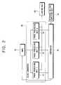
- FIG. 2is a block diagram showing a configuration of a power supply system according to an embodiment of the present invention
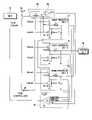
- FIG. 3is a detailed circuit diagram of FIG. 2 ;
- FIG. 4is a flow chart showing a method of controlling the power supply system according to the embodiment of the present invention.
- FIG. 2is a block diagram showing a configuration of a power supply system according to an embodiment of the present invention.
- the power supply systemcomprises an SMPS 10 as a power supplying unit, and a DC/DC converter 24 converting DC power supplied from the SMPS 10 into a plurality of voltage levels, as needed, for each component of a computer system.
- the SMPS 10rectifies a commercial AC power inputted from an outside into the DC power and transforms the rectified DC power so as to have a voltage of a predetermined level and then outputs the voltage having the predetermined level.
- the DC/DC converter 24operates to receive and to reduce an applied DC voltage output from the SMPS 10 so as to supply the voltage of the predetermined level to a loading unit 40 , and includes a plurality of phase processing units 12 , 14 and 16 to provide a maximum wattage, as needed, for each component (e. g., a CPU, a chipset, a memory, etc.) of the computer system requiring a high-level of power.
- the present embodimentemploys a DC/DC converter 24 having three phase processing units 12 , 14 and 16 but more or less phase processing units are possible.
- the DC power supplied from the SMPS 10is supplied to the respective phase processing units 12 , 14 and 16 , and a voltage of the power supplied to each of the phase processing units 12 , 14 and 16 is reduced by a switching process of each of the phase processing units 12 , 14 and 16 in response to a waveform of a pulse width modulation (PWM) generated in a PWM controller 26 (see FIG. 3 ) connected to each of the phase processing units 12 , 14 and 16 .
- PWMpulse width modulation
- the power supply systemincludes a comparator 20 comparing the voltage corresponding to a phase current flowing in each of the phase processing units 12 , 14 and 16 with a predetermined reference voltage, and a reference voltage supplying unit 22 supplying the predetermined reference voltage to the comparator 20 .
- the comparator 20compares voltages corresponding to respective phase currents with the predetermined reference voltage and outputs a control signal so as to allow the power from the SMPS 10 to be interrupted where a voltage corresponding to a respective phase current is higher than the predetermined reference voltage. Further, the predetermined reference voltage of the comparator 20 has to be established, which will serve as an indicator to assert whether a distribution of each of the phase currents is uniform.
- the DC/DC converter 24has a plurality of phase processing units 12 , 14 and 16 with which the power supplied from the SMPS 10 is separated into a plurality of phase currents so as to process the plurality of phase currents.
- Each of the phase processing units 12 , 14 and 16comprises an FET (Field Effect Transistor) as a switching element, an inductor ( L 2 , L 3 or L 4 ), and a capacitor (C 1 , C 2 or C 3 ), respectively.
- a PWM controller 26to control a turn on/turn off of the FET (FET_high, FET_low) is provided in the DC/DC converter.
- the PWM controller 26outputs a predetermined pulse width modulation signal to each of the FETs (FET_high, FET_low) to initiate a switching process of the FETs (FET_high, FET_low).
- FET_high, FET_lowa predetermined voltage is output to the loading unit 40 .
- voltagesare provided by discharging the respective capacitor C 1 , C 2 , and C 3 through respective inductors L 2 , L 3 and L 4 , connected to the FETs (FET_high, FET_low).
- the voltages between first and second terminals of each of the capacitors C 1 , C 2 , and C 3induce a voltage to a common node connecting the terminals of respective sets of FETs (FET_high, FET_low).
- the induced voltages across the terminals of each of the FET_lowsindicate an amount of current flowing in respective phase processing units 12 , 14 and 16 .
- the induced voltageis sensed as a voltage across a resistance value (Rds_on) of the resistor connected between a source terminal and a drain terminal of the FET_low as the FET_low turns on. Accordingly, the phase current of each of the phase processing units 12 , 14 and 16 is output to the comparator 20 .
- each of the sensed phase currents, sensed by the resistance value (Rds_on) as a voltageis applied to a non-inverting input terminal (+) of the comparator 20 , thereby causing a potential difference to be generated, and the voltage is compared with the reference voltage applied to an inverting terminal ( ⁇ ) of the comparator 20 .
- the reference voltageis defined as the voltage output by allowing the voltage inducted to first and second terminals of the inductor L 1 disposed on a power line between the SMPS 10 and the phase processing units 12 , 14 and 16 to be output through an amplifier 28 . This is available because of a design based on the current flowing toward the phase processing units 12 , 14 and 16 from a power source.
- the SMPS 10can reduce an error since the DC/DC converter 24 has a plurality of phase processing units 12 , 14 and 16 , distributes the current flowing from the SMPS 10 into a plurality of phases and supplies the plurality of phase currents to the loading unit 40 .
- An amplification rate by the amplifier 28is established so that the reference voltage approximately coincides with the voltage value corresponding to a maximum current as required by each of the phase processing units 12 , 14 and 16 .
- the comparator 20compares a voltage corresponding to each of the phase currents with the reference voltage. If the voltage of a phase current is higher than the reference voltage, the comparator 20 outputs a high level signal. If the voltage of a phase current is lower than the reference voltage, the comparator 20 outputs a low level signal.
- the output signalis applied to the SMPS 10 as a PS-ON signal. That is, since an output line of the comparator 20 is connected to a PS-ON pin to which the PS-ON signal is applied, among pins of a connector connecting the SMPS 10 and a motherboard, the output signal of the comparator is applied as the PS_ON signal.
- the PS_ON signalis output from a condition sensing circuit provided in the motherboard and supplied to the SMPS 10 when a power switch of a computer system is turned on, to thereby allow the SMPS 10 to supply the power to each component installed in the motherboard.
- the poweris supplied when the output of the comparator 20 is the low level signal which is applied to the SMPS 10 .
- the high level signalis output as an output signal of the comparator 20 , serving as a PS_ON signal, an output power of the SMPS is interrupted. If the low level signal is output, as an output signal of the comparator 20 , the power supply is normally performed.
- a resistance value (Rds-on) of the FETis about 10 m ⁇ when the computer system is turned on, and the potential difference of 20 mV is generated across first and second terminals of the FET (FET_low) where the maximum phase current is 20 A.
- Thisis established as the reference voltage. That is, the voltage when the potential difference generated across the first and second terminals of the inductor L 1 provided between the SMPS 10 and the phase processing units 12 , 14 and 16 and output by the amplifier 28 is 20 mV.
- the current from the SMPS 10is, respectively, distributed by about 33% to each of the phase processing units 12 , 14 and 16 and the distributed currents are supplied to the loading unit 40 , and thus, the voltages corresponding to each of the respective phase currents are uniform below 20 mV.
- the other two phase processing unitsrespectively distribute the current from the SMPs 10 by 50% rather than by 33% to each of the other two phase processing units 12 , 14 and 16 and supply the distributed currents to the loading unit 40 . Accordingly, the voltages corresponding to the remaining phase currents are over 20 mV.
- the comparator 20outputs the high level signal to interrupt the power supply to the loading unit 40 .
- the power supplycan directly sense the excessive flows and interrupt the power supply, thereby being able to safely protect the system from damages.
- FIG. 4The method of controlling the power supply system according to the embodiment of the present invention is shown in FIG. 4 .
- a power of the SMPS 10is supplied to a DC/DC converter 24 having a plurality of phase processing units 12 , 14 and 16 at operation S 10 .
- a phase currentis sensed as the FET_Low of each of the phase processing units 12 , 14 and 16 is turned on at operation S 12 , and a potential difference is generated when a voltage corresponding to the sensed phase current is applied to an input terminal of the comparator 20 .
- the voltage corresponding to the sensed phase currentis compared with the predetermined reference voltage supplied from a reference voltage supplying unit 22 at operation S 14 .
- the high level signalis output at operation S 18 .
- the low level signalis output at operation S 20 .
- the signal of the high and/or the low levelis applied as a PS_ON signal of the SMPS 10 .
- the power supply of the SMPS 10is interrupted at operation S 22 .
- the low level signalis applied, the SMPS 10 normally operates to supply the power at operation S 24 .
- the comparator 20 and the reference voltage supplying unit 22are provided separately from the DC/DC converter 24 , but the comparator 20 and the reference voltage supplying unit 22 may be provided within the DC/DC converter 24 .
- the output signal of the comparator 20is supplied to the SMPS 10 to interrupt the power supply.
- the switching unitis controllable according to a control signal to interrupt the power supply.
- the switching unitmay be an electronic switch operating responsively to the control signal to interrupt the power supply.
- the output signal of the comparator 20is supplied to the SMPS 10 to interrupt the power supply from the SMPS 10 .
- an interruption of the power supplyis realizable by a microcomputer programmed so as to control the SMPS 10 where the voltage corresponding to a phase current is higher than the predetermined reference voltage after comparing the voltage generated based on the phase current flowing in each of the phase processing units 12 , 14 and 16 with the predetermined reference voltage.
- the DC/DC converter 24 having the three phase processing units 12 , 14 and 16has been described as an example.
- the present inventioncan employ any type of DC/DC converter that has a plurality of phase processing units, regardless of a number of the phase processing units.
- the present inventioncan serve to prevent damage to components of a computer system due to abnormal distribution of phase currents, by sensing the amount of each of the phase currents flowing in the DC/DC converter having a plurality of phase processing units.
- a power supply system and a method of controlling the sameis provided, wherein a computer system can be prevented from damage by immediately sensing unequal distribution of currents flowing in each of the phase processing units.
Landscapes
- Engineering & Computer Science (AREA)
- Power Engineering (AREA)
- Dc-Dc Converters (AREA)
Abstract
Description
Claims (19)
Applications Claiming Priority (2)
| Application Number | Priority Date | Filing Date | Title |
|---|---|---|---|
| JP2002-79166 | 2002-12-12 | ||
| KR1020020079166AKR100960038B1 (en) | 2002-12-12 | 2002-12-12 | Power supply system and its control method |
Publications (2)
| Publication Number | Publication Date |
|---|---|
| US20050001599A1 US20050001599A1 (en) | 2005-01-06 |
| US7126315B2true US7126315B2 (en) | 2006-10-24 |
Family
ID=33550109
Family Applications (1)
| Application Number | Title | Priority Date | Filing Date |
|---|---|---|---|
| US10/732,819Expired - Fee RelatedUS7126315B2 (en) | 2002-12-12 | 2003-12-11 | DC/DC Converter with input and output current sensing and over current protection capable of interrupting the input power supply |
Country Status (3)
| Country | Link |
|---|---|
| US (1) | US7126315B2 (en) |
| KR (1) | KR100960038B1 (en) |
| TW (1) | TW200410064A (en) |
Cited By (16)
| Publication number | Priority date | Publication date | Assignee | Title |
|---|---|---|---|---|
| US20070024360A1 (en)* | 2005-07-27 | 2007-02-01 | Artesyn Technologies, Inc. | Power supply providing ultrafast modulation of output voltage |
| US20080207237A1 (en)* | 2005-04-14 | 2008-08-28 | Koninklijke Philips Electronics N.V. | Communication in Phase Shifted Driven Power Converters |
| US20080224769A1 (en)* | 2007-03-13 | 2008-09-18 | Piotr Markowski | Power supply providing ultrafast modulation of output voltage |
| US20090091305A1 (en)* | 2007-10-08 | 2009-04-09 | Piotr Markowski | Linear regulator |
| US20090141411A1 (en)* | 2007-11-29 | 2009-06-04 | Hong Fu Jin Precision Industry(Shenzhen) Co., Ltd. | Voltage regulator module control circuit |
| US7589514B1 (en) | 2005-10-03 | 2009-09-15 | Zilker Labs, Inc. | Method for accurate current sensing in power converters |
| US20100019576A1 (en)* | 2008-07-24 | 2010-01-28 | International Business Machines Corporation | Dynamically Configuring Current Sharing And Fault Monitoring In Redundant Power Supply Modules |
| US20100315847A1 (en)* | 2009-06-16 | 2010-12-16 | Intersil Americas Inc. | Component fault detection for use with a multi-phase dc-dc converter |
| US20120319668A1 (en)* | 2011-06-17 | 2012-12-20 | Hon Hai Precision Industry Co., Ltd. | Power supply circuit with protection circuit |
| TWI420285B (en)* | 2007-12-14 | 2013-12-21 | Hon Hai Prec Ind Co Ltd | Vrm control circuit for motherboard |
| US20140175888A1 (en)* | 2012-12-21 | 2014-06-26 | Infineon Technologies Austria Ag | Power Converter Circuit with AC Output |
| US9418864B2 (en) | 2008-01-30 | 2016-08-16 | Infineon Technologies Ag | Method of forming a non volatile memory device using wet etching |
| US9425622B2 (en) | 2013-01-08 | 2016-08-23 | Infineon Technologies Austria Ag | Power converter circuit with AC output and at least one transformer |
| US9461474B2 (en) | 2012-01-17 | 2016-10-04 | Infineon Technologies Austria Ag | Power converter circuit with AC output |
| US9478989B2 (en) | 2012-01-17 | 2016-10-25 | Infineon Technologies Austria Ag | Power converter circuit with AC output |
| US9484746B2 (en) | 2012-01-17 | 2016-11-01 | Infineon Technologies Austria Ag | Power converter circuit with AC output |
Families Citing this family (6)
| Publication number | Priority date | Publication date | Assignee | Title |
|---|---|---|---|---|
| US20050068793A1 (en)* | 2003-09-30 | 2005-03-31 | Dorian Davies | Pulse width modulated power supply |
| US7161335B2 (en)* | 2004-02-20 | 2007-01-09 | Virginia Tech Intellectual Properties, Inc. | Adaptive bus voltage positioning for two-stage voltage regulators |
| KR100909960B1 (en) | 2004-12-28 | 2009-07-29 | 삼성전자주식회사 | Power supply voltage control device and method in multiple interface card |
| US8704500B2 (en)* | 2007-08-14 | 2014-04-22 | Intersil Americas LLC | Sensing a phase-path current in a multiphase power supply such as a coupled-inductor power supply |
| JP5442307B2 (en) | 2009-04-22 | 2014-03-12 | 株式会社日立メディコ | Mobile X-ray device |
| TWI411908B (en)* | 2009-10-01 | 2013-10-11 | Qisda Corp | A power supply and a developing device using the same |
Citations (15)
| Publication number | Priority date | Publication date | Assignee | Title |
|---|---|---|---|---|
| JPS60198613A (en) | 1984-03-21 | 1985-10-08 | Nec Corp | Automatic 3-phase voltage control system |
| KR940025144A (en) | 1993-04-17 | 1994-11-19 | 이희종 | Phase detection circuit of converter controller |
| KR970013557A (en) | 1995-08-31 | 1997-03-29 | 배순훈 | Overvoltage Protection Circuit of Power Supply |
| US5712754A (en)* | 1996-04-15 | 1998-01-27 | Compaq Computer Corporation | Hot plug protection system |
| KR19980057257A (en) | 1996-12-30 | 1998-09-25 | 배순훈 | Switching voltage variable circuit of switching mode power supply |
| JPH11220884A (en) | 1998-02-03 | 1999-08-10 | Hitachi Ltd | Protection device for self-excited converter, control device for variable speed generator motor system, and control device for self-extinguishing converter |
| JP2000014163A (en) | 1998-06-26 | 2000-01-14 | Matsushita Electric Works Ltd | Distribution type power supply unit with protective function from overcurrent |
| JP2000078439A (en) | 1998-08-27 | 2000-03-14 | Nec Eng Ltd | Delay circuit for video signal using field memory |
| US6127814A (en)* | 1998-11-23 | 2000-10-03 | Switch Power, Inc. | System to protect switch mode DC/DC converters against overload current |
| KR200203131Y1 (en) | 1997-11-21 | 2000-12-01 | 구자홍 | Safety circuit for power supply of cpu |
| US6218816B1 (en)* | 1999-10-20 | 2001-04-17 | Eaton Corporation | Power supply with control circuit for short circuit detection and excess current protection |
| KR20010057241A (en) | 1999-12-20 | 2001-07-04 | 박태진 | Apparatus for supplying power having a overcurrent protection circuit |
| US6366068B1 (en) | 1999-09-06 | 2002-04-02 | Murata Manufacturing, Co., Ltd. | Switching power supply with overcurrent protection and method |
| US6385024B1 (en)* | 2000-03-07 | 2002-05-07 | Ss8 Networks, Inc. | System and method for monitoring current consumption from current share components |
| US6414470B1 (en)* | 2002-01-22 | 2002-07-02 | Richtek Technology Corp. | Apparatus and method for balancing channel currents in a multi-phase DC-to-DC converter |
Family Cites Families (6)
| Publication number | Priority date | Publication date | Assignee | Title |
|---|---|---|---|---|
| KR910006299Y1 (en)* | 1989-10-13 | 1991-08-22 | 삼성전자 주식회사 | Overvoltage Control Circuit |
| JP3480201B2 (en)* | 1996-11-06 | 2003-12-15 | 松下電器産業株式会社 | Interleaved switching converter |
| US6222352B1 (en)* | 1999-05-06 | 2001-04-24 | Fairchild Semiconductor Corporation | Multiple voltage output buck converter with a single inductor |
| KR100401100B1 (en)* | 2000-11-22 | 2003-10-10 | 삼성전기주식회사 | Back-light inverter of LCD |
| KR100393012B1 (en)* | 2001-10-15 | 2003-07-31 | 주식회사 다윈전자 | Temperature detecting device for high-power electric system |
| KR20050111178A (en)* | 2004-05-21 | 2005-11-24 | 삼성에스디아이 주식회사 | Discharge display apparatus wherein electric potentials are efficiently monitored |
- 2002
- 2002-12-12KRKR1020020079166Apatent/KR100960038B1/ennot_activeExpired - Fee Related
- 2003
- 2003-10-14TWTW092128385Apatent/TW200410064A/enunknown
- 2003-12-11USUS10/732,819patent/US7126315B2/ennot_activeExpired - Fee Related
Patent Citations (15)
| Publication number | Priority date | Publication date | Assignee | Title |
|---|---|---|---|---|
| JPS60198613A (en) | 1984-03-21 | 1985-10-08 | Nec Corp | Automatic 3-phase voltage control system |
| KR940025144A (en) | 1993-04-17 | 1994-11-19 | 이희종 | Phase detection circuit of converter controller |
| KR970013557A (en) | 1995-08-31 | 1997-03-29 | 배순훈 | Overvoltage Protection Circuit of Power Supply |
| US5712754A (en)* | 1996-04-15 | 1998-01-27 | Compaq Computer Corporation | Hot plug protection system |
| KR19980057257A (en) | 1996-12-30 | 1998-09-25 | 배순훈 | Switching voltage variable circuit of switching mode power supply |
| KR200203131Y1 (en) | 1997-11-21 | 2000-12-01 | 구자홍 | Safety circuit for power supply of cpu |
| JPH11220884A (en) | 1998-02-03 | 1999-08-10 | Hitachi Ltd | Protection device for self-excited converter, control device for variable speed generator motor system, and control device for self-extinguishing converter |
| JP2000014163A (en) | 1998-06-26 | 2000-01-14 | Matsushita Electric Works Ltd | Distribution type power supply unit with protective function from overcurrent |
| JP2000078439A (en) | 1998-08-27 | 2000-03-14 | Nec Eng Ltd | Delay circuit for video signal using field memory |
| US6127814A (en)* | 1998-11-23 | 2000-10-03 | Switch Power, Inc. | System to protect switch mode DC/DC converters against overload current |
| US6366068B1 (en) | 1999-09-06 | 2002-04-02 | Murata Manufacturing, Co., Ltd. | Switching power supply with overcurrent protection and method |
| US6218816B1 (en)* | 1999-10-20 | 2001-04-17 | Eaton Corporation | Power supply with control circuit for short circuit detection and excess current protection |
| KR20010057241A (en) | 1999-12-20 | 2001-07-04 | 박태진 | Apparatus for supplying power having a overcurrent protection circuit |
| US6385024B1 (en)* | 2000-03-07 | 2002-05-07 | Ss8 Networks, Inc. | System and method for monitoring current consumption from current share components |
| US6414470B1 (en)* | 2002-01-22 | 2002-07-02 | Richtek Technology Corp. | Apparatus and method for balancing channel currents in a multi-phase DC-to-DC converter |
Non-Patent Citations (2)
| Title |
|---|
| Enrico Dallago; Lossless Current Sensing in Low-Voltage High-Current DC/DC Modular Supplies; Member IEEE; 2000. |
| Triple Synchronous Buck Controller with NMOS LDO Controller; Texas Instruments Incorporated; 2002. |
Cited By (38)
| Publication number | Priority date | Publication date | Assignee | Title |
|---|---|---|---|---|
| US20080207237A1 (en)* | 2005-04-14 | 2008-08-28 | Koninklijke Philips Electronics N.V. | Communication in Phase Shifted Driven Power Converters |
| US7990214B2 (en) | 2005-07-27 | 2011-08-02 | Artesyn Technologies, Inc. | Power supply providing ultrafast modulation of output voltage |
| US7602155B2 (en)* | 2005-07-27 | 2009-10-13 | Artesyn Technologies, Inc. | Power supply providing ultrafast modulation of output voltage |
| US20090261908A1 (en)* | 2005-07-27 | 2009-10-22 | Artesyn Technologies, Inc. | Power supply providing ultrafast modulation of output voltage |
| US20070024360A1 (en)* | 2005-07-27 | 2007-02-01 | Artesyn Technologies, Inc. | Power supply providing ultrafast modulation of output voltage |
| US7589514B1 (en) | 2005-10-03 | 2009-09-15 | Zilker Labs, Inc. | Method for accurate current sensing in power converters |
| US20080224769A1 (en)* | 2007-03-13 | 2008-09-18 | Piotr Markowski | Power supply providing ultrafast modulation of output voltage |
| US20090184764A1 (en)* | 2007-03-13 | 2009-07-23 | Piotr Markowski | Power supply providing ultrafast modulation of output voltage |
| US7859336B2 (en) | 2007-03-13 | 2010-12-28 | Astec International Limited | Power supply providing ultrafast modulation of output voltage |
| US7808313B2 (en) | 2007-03-13 | 2010-10-05 | Astec International Limited | Power supply providing ultrafast modulation of output voltage |
| US7994761B2 (en) | 2007-10-08 | 2011-08-09 | Astec International Limited | Linear regulator with RF transistors and a bias adjustment circuit |
| US20090091305A1 (en)* | 2007-10-08 | 2009-04-09 | Piotr Markowski | Linear regulator |
| US20090141411A1 (en)* | 2007-11-29 | 2009-06-04 | Hong Fu Jin Precision Industry(Shenzhen) Co., Ltd. | Voltage regulator module control circuit |
| CN101452331B (en)* | 2007-11-29 | 2012-08-29 | 鸿富锦精密工业(深圳)有限公司 | Motherboard voltage regulation module control circuit |
| US7751158B2 (en)* | 2007-11-29 | 2010-07-06 | Hong Fu Jin Precision Industry (Shenzhen) Co., Ltd. | Voltage regulator module control circuit |
| TWI420285B (en)* | 2007-12-14 | 2013-12-21 | Hon Hai Prec Ind Co Ltd | Vrm control circuit for motherboard |
| US9418864B2 (en) | 2008-01-30 | 2016-08-16 | Infineon Technologies Ag | Method of forming a non volatile memory device using wet etching |
| US20100019576A1 (en)* | 2008-07-24 | 2010-01-28 | International Business Machines Corporation | Dynamically Configuring Current Sharing And Fault Monitoring In Redundant Power Supply Modules |
| US9214809B2 (en) | 2008-07-24 | 2015-12-15 | Lenovo Enterprise Solutions (Singapore) Pte. Ltd. | Dynamically configuring current sharing and fault monitoring in redundant power supply modules |
| US8217531B2 (en)* | 2008-07-24 | 2012-07-10 | International Business Machines Corporation | Dynamically configuring current sharing and fault monitoring in redundant power supply modules |
| TWI487254B (en)* | 2009-06-16 | 2015-06-01 | Intersil Inc | Dc-dc converters that correct for way out of balance (wob) conditions, methods for use with said dc-dc converters, systems that correct for wob conditions, and wob rebalancers for use with dc-dc converters |
| TWI487925B (en)* | 2009-06-16 | 2015-06-11 | Intersil Inc | Component fault detection for use with a multi-phase dc-dc converter |
| US8378650B2 (en) | 2009-06-16 | 2013-02-19 | Intersil Americas Inc. | Way out of balance (WOB) current correction for use with a multi-phase DC-DC converter |
| US8385030B2 (en)* | 2009-06-16 | 2013-02-26 | Intersil Americas Inc. | Component fault detection for use with a multi-phase DC-DC converter |
| US20100315051A1 (en)* | 2009-06-16 | 2010-12-16 | Intersil Americas Inc. | Way out of balance (wob) current correction for use with a multi-phase dc-dc converter |
| CN101924464B (en)* | 2009-06-16 | 2014-06-11 | 英特赛尔美国股份有限公司 | Component fault detection for use with a multi-phase DC-DC converter |
| US20100315847A1 (en)* | 2009-06-16 | 2010-12-16 | Intersil Americas Inc. | Component fault detection for use with a multi-phase dc-dc converter |
| CN101924468B (en)* | 2009-06-16 | 2015-01-14 | 英特赛尔美国股份有限公司 | Excessive Out of Balance (WOB) Current Correction for Multiphase DC-DC Converters |
| CN101924468A (en)* | 2009-06-16 | 2010-12-22 | 英特赛尔美国股份有限公司 | Extraordinary imbalance (WOB) current correction for use with a multiphase DC-DC converter |
| CN101924464A (en)* | 2009-06-16 | 2010-12-22 | 英特赛尔美国股份有限公司 | Component Fault Detection for Multiphase DC-DC Converters |
| US20120319668A1 (en)* | 2011-06-17 | 2012-12-20 | Hon Hai Precision Industry Co., Ltd. | Power supply circuit with protection circuit |
| US9461474B2 (en) | 2012-01-17 | 2016-10-04 | Infineon Technologies Austria Ag | Power converter circuit with AC output |
| US9478989B2 (en) | 2012-01-17 | 2016-10-25 | Infineon Technologies Austria Ag | Power converter circuit with AC output |
| US9484746B2 (en) | 2012-01-17 | 2016-11-01 | Infineon Technologies Austria Ag | Power converter circuit with AC output |
| US10084317B2 (en) | 2012-01-17 | 2018-09-25 | Infineon Technologies Austria Ag | Power converter circuit with AC output |
| US9401663B2 (en)* | 2012-12-21 | 2016-07-26 | Infineon Technologies Austria Ag | Power converter circuit with AC output |
| US20140175888A1 (en)* | 2012-12-21 | 2014-06-26 | Infineon Technologies Austria Ag | Power Converter Circuit with AC Output |
| US9425622B2 (en) | 2013-01-08 | 2016-08-23 | Infineon Technologies Austria Ag | Power converter circuit with AC output and at least one transformer |
Also Published As
| Publication number | Publication date |
|---|---|
| US20050001599A1 (en) | 2005-01-06 |
| KR20040051267A (en) | 2004-06-18 |
| TW200410064A (en) | 2004-06-16 |
| KR100960038B1 (en) | 2010-05-31 |
Similar Documents
| Publication | Publication Date | Title |
|---|---|---|
| US7126315B2 (en) | DC/DC Converter with input and output current sensing and over current protection capable of interrupting the input power supply | |
| US7498783B2 (en) | Extending the continuous mode of operation for a buck converter | |
| US6014322A (en) | Power supply unit, parallel operation control circuit applied thereto, and parallel operation control method | |
| US6977447B2 (en) | Method and apparatus for regulating multiple outputs of a single inductor DC to DC converter | |
| CN114389455A (en) | Trans-inductance multiphase power converter and control | |
| US7429806B2 (en) | Smart power supply | |
| US7505702B2 (en) | High power supply to control an abnormal load | |
| US20140286058A1 (en) | Undervoltage protection circuit, undervoltage protection method and switching power supply | |
| US7380146B2 (en) | Power management system | |
| US11601058B2 (en) | Multi-phase power regulator | |
| US7432694B2 (en) | Systems and methods for sensed current-mode feedback in switching regulators | |
| US20060285369A1 (en) | Switching mode power supply with active load detection function, and swithcing method thereof | |
| US10756626B2 (en) | Power conversion circuit | |
| US20050141158A1 (en) | Overvoltage projection circuit | |
| US12062986B2 (en) | Dual path and mode start-up circuit | |
| US7286330B2 (en) | Power supply device and method having a spark prevention function | |
| US8184416B2 (en) | Inverter driver and lamp driver thereof | |
| US7352159B2 (en) | System and method for managing negative voltage in a power supply overvoltage failure event | |
| US20060092672A1 (en) | High-voltage generator and method of controlling high voltage | |
| US7602163B2 (en) | Coupled inductor output regulation | |
| JPH10243635A (en) | Power supply | |
| US20250116728A1 (en) | Open fault detection for power converters | |
| US8619440B2 (en) | Over current protection method used in a switched-mode power supply and related controller | |
| JPH0686454A (en) | Power device | |
| KR100241556B1 (en) | Logic circuit protection apparatus of ecr |
Legal Events
| Date | Code | Title | Description |
|---|---|---|---|
| AS | Assignment | Owner name:SAMSUNG ELECTRONICS CO., LTD., KOREA, REPUBLIC OF Free format text:ASSIGNMENT OF ASSIGNORS INTEREST;ASSIGNOR:SEO, KWANG-YOUM;REEL/FRAME:015763/0574 Effective date:20030529 | |
| AS | Assignment | Owner name:SAMSUNG ELECTRONICS CO., LTD., KOREA, REPUBLIC OF Free format text:CORRECTIVE ASSIGNMENT TO CORRECT THE ASSIGNOR'S NAME, PREVIOUSLY RECORDED ON REEL 015763 FRAME 0574;ASSIGNOR:SEO, KWANG-YOUN;REEL/FRAME:016201/0004 Effective date:20030529 | |
| FEPP | Fee payment procedure | Free format text:PAYOR NUMBER ASSIGNED (ORIGINAL EVENT CODE: ASPN); ENTITY STATUS OF PATENT OWNER: LARGE ENTITY | |
| FPAY | Fee payment | Year of fee payment:4 | |
| FEPP | Fee payment procedure | Free format text:PAYOR NUMBER ASSIGNED (ORIGINAL EVENT CODE: ASPN); ENTITY STATUS OF PATENT OWNER: LARGE ENTITY Free format text:PAYER NUMBER DE-ASSIGNED (ORIGINAL EVENT CODE: RMPN); ENTITY STATUS OF PATENT OWNER: LARGE ENTITY | |
| FPAY | Fee payment | Year of fee payment:8 | |
| FEPP | Fee payment procedure | Free format text:MAINTENANCE FEE REMINDER MAILED (ORIGINAL EVENT CODE: REM.) | |
| LAPS | Lapse for failure to pay maintenance fees | Free format text:PATENT EXPIRED FOR FAILURE TO PAY MAINTENANCE FEES (ORIGINAL EVENT CODE: EXP.); ENTITY STATUS OF PATENT OWNER: LARGE ENTITY | |
| STCH | Information on status: patent discontinuation | Free format text:PATENT EXPIRED DUE TO NONPAYMENT OF MAINTENANCE FEES UNDER 37 CFR 1.362 | |
| FP | Lapsed due to failure to pay maintenance fee | Effective date:20181024 |