US7125464B2 - Method for manufacturing an endovascular graft section - Google Patents
Method for manufacturing an endovascular graft sectionDownload PDFInfo
- Publication number
- US7125464B2 US7125464B2US10/029,557US2955701AUS7125464B2US 7125464 B2US7125464 B2US 7125464B2US 2955701 AUS2955701 AUS 2955701AUS 7125464 B2US7125464 B2US 7125464B2
- Authority
- US
- United States
- Prior art keywords
- fusible material
- layers
- layer
- inflatable channel
- channel
- Prior art date
- Legal status (The legal status is an assumption and is not a legal conclusion. Google has not performed a legal analysis and makes no representation as to the accuracy of the status listed.)
- Expired - Lifetime, expires
Links
Images


Classifications
- B—PERFORMING OPERATIONS; TRANSPORTING
- B29—WORKING OF PLASTICS; WORKING OF SUBSTANCES IN A PLASTIC STATE IN GENERAL
- B29C—SHAPING OR JOINING OF PLASTICS; SHAPING OF MATERIAL IN A PLASTIC STATE, NOT OTHERWISE PROVIDED FOR; AFTER-TREATMENT OF THE SHAPED PRODUCTS, e.g. REPAIRING
- B29C65/00—Joining or sealing of preformed parts, e.g. welding of plastics materials; Apparatus therefor
- B29C65/02—Joining or sealing of preformed parts, e.g. welding of plastics materials; Apparatus therefor by heating, with or without pressure
- B29C65/18—Joining or sealing of preformed parts, e.g. welding of plastics materials; Apparatus therefor by heating, with or without pressure using heated tools
- A—HUMAN NECESSITIES
- A61—MEDICAL OR VETERINARY SCIENCE; HYGIENE
- A61F—FILTERS IMPLANTABLE INTO BLOOD VESSELS; PROSTHESES; DEVICES PROVIDING PATENCY TO, OR PREVENTING COLLAPSING OF, TUBULAR STRUCTURES OF THE BODY, e.g. STENTS; ORTHOPAEDIC, NURSING OR CONTRACEPTIVE DEVICES; FOMENTATION; TREATMENT OR PROTECTION OF EYES OR EARS; BANDAGES, DRESSINGS OR ABSORBENT PADS; FIRST-AID KITS
- A61F2/00—Filters implantable into blood vessels; Prostheses, i.e. artificial substitutes or replacements for parts of the body; Appliances for connecting them with the body; Devices providing patency to, or preventing collapsing of, tubular structures of the body, e.g. stents
- A61F2/02—Prostheses implantable into the body
- A61F2/04—Hollow or tubular parts of organs, e.g. bladders, tracheae, bronchi or bile ducts
- A61F2/06—Blood vessels
- A61F2/07—Stent-grafts
- B—PERFORMING OPERATIONS; TRANSPORTING
- B29—WORKING OF PLASTICS; WORKING OF SUBSTANCES IN A PLASTIC STATE IN GENERAL
- B29C—SHAPING OR JOINING OF PLASTICS; SHAPING OF MATERIAL IN A PLASTIC STATE, NOT OTHERWISE PROVIDED FOR; AFTER-TREATMENT OF THE SHAPED PRODUCTS, e.g. REPAIRING
- B29C53/00—Shaping by bending, folding, twisting, straightening or flattening; Apparatus therefor
- B29C53/36—Bending and joining, e.g. for making hollow articles
- B29C53/38—Bending and joining, e.g. for making hollow articles by bending sheets or strips at right angles to the longitudinal axis of the article being formed and joining the edges
- B29C53/40—Bending and joining, e.g. for making hollow articles by bending sheets or strips at right angles to the longitudinal axis of the article being formed and joining the edges for articles of definite length, i.e. discrete articles
- B29C53/42—Bending and joining, e.g. for making hollow articles by bending sheets or strips at right angles to the longitudinal axis of the article being formed and joining the edges for articles of definite length, i.e. discrete articles using internal forming surfaces, e.g. mandrels
- B29C53/44—Bending and joining, e.g. for making hollow articles by bending sheets or strips at right angles to the longitudinal axis of the article being formed and joining the edges for articles of definite length, i.e. discrete articles using internal forming surfaces, e.g. mandrels rotatable about the axis of the article
- B—PERFORMING OPERATIONS; TRANSPORTING
- B29—WORKING OF PLASTICS; WORKING OF SUBSTANCES IN A PLASTIC STATE IN GENERAL
- B29C—SHAPING OR JOINING OF PLASTICS; SHAPING OF MATERIAL IN A PLASTIC STATE, NOT OTHERWISE PROVIDED FOR; AFTER-TREATMENT OF THE SHAPED PRODUCTS, e.g. REPAIRING
- B29C65/00—Joining or sealing of preformed parts, e.g. welding of plastics materials; Apparatus therefor
- B29C65/48—Joining or sealing of preformed parts, e.g. welding of plastics materials; Apparatus therefor using adhesives, i.e. using supplementary joining material; solvent bonding
- B29C65/4805—Joining or sealing of preformed parts, e.g. welding of plastics materials; Apparatus therefor using adhesives, i.e. using supplementary joining material; solvent bonding characterised by the type of adhesives
- B29C65/481—Non-reactive adhesives, e.g. physically hardening adhesives
- B29C65/4815—Hot melt adhesives, e.g. thermoplastic adhesives
- B—PERFORMING OPERATIONS; TRANSPORTING
- B29—WORKING OF PLASTICS; WORKING OF SUBSTANCES IN A PLASTIC STATE IN GENERAL
- B29C—SHAPING OR JOINING OF PLASTICS; SHAPING OF MATERIAL IN A PLASTIC STATE, NOT OTHERWISE PROVIDED FOR; AFTER-TREATMENT OF THE SHAPED PRODUCTS, e.g. REPAIRING
- B29C66/00—General aspects of processes or apparatus for joining preformed parts
- B29C66/01—General aspects dealing with the joint area or with the area to be joined
- B29C66/05—Particular design of joint configurations
- B29C66/10—Particular design of joint configurations particular design of the joint cross-sections
- B29C66/11—Joint cross-sections comprising a single joint-segment, i.e. one of the parts to be joined comprising a single joint-segment in the joint cross-section
- B29C66/112—Single lapped joints
- B29C66/1122—Single lap to lap joints, i.e. overlap joints
- B—PERFORMING OPERATIONS; TRANSPORTING
- B29—WORKING OF PLASTICS; WORKING OF SUBSTANCES IN A PLASTIC STATE IN GENERAL
- B29C—SHAPING OR JOINING OF PLASTICS; SHAPING OF MATERIAL IN A PLASTIC STATE, NOT OTHERWISE PROVIDED FOR; AFTER-TREATMENT OF THE SHAPED PRODUCTS, e.g. REPAIRING
- B29C66/00—General aspects of processes or apparatus for joining preformed parts
- B29C66/01—General aspects dealing with the joint area or with the area to be joined
- B29C66/05—Particular design of joint configurations
- B29C66/10—Particular design of joint configurations particular design of the joint cross-sections
- B29C66/12—Joint cross-sections combining only two joint-segments; Tongue and groove joints; Tenon and mortise joints; Stepped joint cross-sections
- B29C66/122—Joint cross-sections combining only two joint-segments, i.e. one of the parts to be joined comprising only two joint-segments in the joint cross-section
- B29C66/1226—Joint cross-sections combining only two joint-segments, i.e. one of the parts to be joined comprising only two joint-segments in the joint cross-section comprising at least one bevelled joint-segment
- B29C66/12261—Joint cross-sections combining only two joint-segments, i.e. one of the parts to be joined comprising only two joint-segments in the joint cross-section comprising at least one bevelled joint-segment the two joint-segments being bevelled, e.g. the two joint-segments forming a V
- B—PERFORMING OPERATIONS; TRANSPORTING
- B29—WORKING OF PLASTICS; WORKING OF SUBSTANCES IN A PLASTIC STATE IN GENERAL
- B29C—SHAPING OR JOINING OF PLASTICS; SHAPING OF MATERIAL IN A PLASTIC STATE, NOT OTHERWISE PROVIDED FOR; AFTER-TREATMENT OF THE SHAPED PRODUCTS, e.g. REPAIRING
- B29C66/00—General aspects of processes or apparatus for joining preformed parts
- B29C66/40—General aspects of joining substantially flat articles, e.g. plates, sheets or web-like materials; Making flat seams in tubular or hollow articles; Joining single elements to substantially flat surfaces
- B29C66/41—Joining substantially flat articles ; Making flat seams in tubular or hollow articles
- B29C66/43—Joining a relatively small portion of the surface of said articles
- B29C66/432—Joining a relatively small portion of the surface of said articles for making tubular articles or closed loops, e.g. by joining several sheets ; for making hollow articles or hollow preforms
- B29C66/4322—Joining a relatively small portion of the surface of said articles for making tubular articles or closed loops, e.g. by joining several sheets ; for making hollow articles or hollow preforms by joining a single sheet to itself
- B—PERFORMING OPERATIONS; TRANSPORTING
- B29—WORKING OF PLASTICS; WORKING OF SUBSTANCES IN A PLASTIC STATE IN GENERAL
- B29C—SHAPING OR JOINING OF PLASTICS; SHAPING OF MATERIAL IN A PLASTIC STATE, NOT OTHERWISE PROVIDED FOR; AFTER-TREATMENT OF THE SHAPED PRODUCTS, e.g. REPAIRING
- B29C66/00—General aspects of processes or apparatus for joining preformed parts
- B29C66/40—General aspects of joining substantially flat articles, e.g. plates, sheets or web-like materials; Making flat seams in tubular or hollow articles; Joining single elements to substantially flat surfaces
- B29C66/41—Joining substantially flat articles ; Making flat seams in tubular or hollow articles
- B29C66/43—Joining a relatively small portion of the surface of said articles
- B29C66/438—Joining sheets for making hollow-walled, channelled structures or multi-tubular articles
- B—PERFORMING OPERATIONS; TRANSPORTING
- B29—WORKING OF PLASTICS; WORKING OF SUBSTANCES IN A PLASTIC STATE IN GENERAL
- B29C—SHAPING OR JOINING OF PLASTICS; SHAPING OF MATERIAL IN A PLASTIC STATE, NOT OTHERWISE PROVIDED FOR; AFTER-TREATMENT OF THE SHAPED PRODUCTS, e.g. REPAIRING
- B29C66/00—General aspects of processes or apparatus for joining preformed parts
- B29C66/40—General aspects of joining substantially flat articles, e.g. plates, sheets or web-like materials; Making flat seams in tubular or hollow articles; Joining single elements to substantially flat surfaces
- B29C66/49—Internally supporting the, e.g. tubular, article during joining
- B29C66/494—Internally supporting the, e.g. tubular, article during joining using an inflatable core
- B—PERFORMING OPERATIONS; TRANSPORTING
- B29—WORKING OF PLASTICS; WORKING OF SUBSTANCES IN A PLASTIC STATE IN GENERAL
- B29C—SHAPING OR JOINING OF PLASTICS; SHAPING OF MATERIAL IN A PLASTIC STATE, NOT OTHERWISE PROVIDED FOR; AFTER-TREATMENT OF THE SHAPED PRODUCTS, e.g. REPAIRING
- B29C66/00—General aspects of processes or apparatus for joining preformed parts
- B29C66/50—General aspects of joining tubular articles; General aspects of joining long products, i.e. bars or profiled elements; General aspects of joining single elements to tubular articles, hollow articles or bars; General aspects of joining several hollow-preforms to form hollow or tubular articles
- B29C66/65—General aspects of joining tubular articles; General aspects of joining long products, i.e. bars or profiled elements; General aspects of joining single elements to tubular articles, hollow articles or bars; General aspects of joining several hollow-preforms to form hollow or tubular articles with a relative motion between the article and the welding tool
- B—PERFORMING OPERATIONS; TRANSPORTING
- B29—WORKING OF PLASTICS; WORKING OF SUBSTANCES IN A PLASTIC STATE IN GENERAL
- B29C—SHAPING OR JOINING OF PLASTICS; SHAPING OF MATERIAL IN A PLASTIC STATE, NOT OTHERWISE PROVIDED FOR; AFTER-TREATMENT OF THE SHAPED PRODUCTS, e.g. REPAIRING
- B29C66/00—General aspects of processes or apparatus for joining preformed parts
- B29C66/70—General aspects of processes or apparatus for joining preformed parts characterised by the composition, physical properties or the structure of the material of the parts to be joined; Joining with non-plastics material
- B29C66/71—General aspects of processes or apparatus for joining preformed parts characterised by the composition, physical properties or the structure of the material of the parts to be joined; Joining with non-plastics material characterised by the composition of the plastics material of the parts to be joined
- B—PERFORMING OPERATIONS; TRANSPORTING
- B29—WORKING OF PLASTICS; WORKING OF SUBSTANCES IN A PLASTIC STATE IN GENERAL
- B29C—SHAPING OR JOINING OF PLASTICS; SHAPING OF MATERIAL IN A PLASTIC STATE, NOT OTHERWISE PROVIDED FOR; AFTER-TREATMENT OF THE SHAPED PRODUCTS, e.g. REPAIRING
- B29C66/00—General aspects of processes or apparatus for joining preformed parts
- B29C66/70—General aspects of processes or apparatus for joining preformed parts characterised by the composition, physical properties or the structure of the material of the parts to be joined; Joining with non-plastics material
- B29C66/73—General aspects of processes or apparatus for joining preformed parts characterised by the composition, physical properties or the structure of the material of the parts to be joined; Joining with non-plastics material characterised by the intensive physical properties of the material of the parts to be joined, by the optical properties of the material of the parts to be joined, by the extensive physical properties of the parts to be joined, by the state of the material of the parts to be joined or by the material of the parts to be joined being a thermoplastic or a thermoset
- B29C66/737—General aspects of processes or apparatus for joining preformed parts characterised by the composition, physical properties or the structure of the material of the parts to be joined; Joining with non-plastics material characterised by the intensive physical properties of the material of the parts to be joined, by the optical properties of the material of the parts to be joined, by the extensive physical properties of the parts to be joined, by the state of the material of the parts to be joined or by the material of the parts to be joined being a thermoplastic or a thermoset characterised by the state of the material of the parts to be joined
- B29C66/7371—General aspects of processes or apparatus for joining preformed parts characterised by the composition, physical properties or the structure of the material of the parts to be joined; Joining with non-plastics material characterised by the intensive physical properties of the material of the parts to be joined, by the optical properties of the material of the parts to be joined, by the extensive physical properties of the parts to be joined, by the state of the material of the parts to be joined or by the material of the parts to be joined being a thermoplastic or a thermoset characterised by the state of the material of the parts to be joined oriented or heat-shrinkable
- B29C66/73711—General aspects of processes or apparatus for joining preformed parts characterised by the composition, physical properties or the structure of the material of the parts to be joined; Joining with non-plastics material characterised by the intensive physical properties of the material of the parts to be joined, by the optical properties of the material of the parts to be joined, by the extensive physical properties of the parts to be joined, by the state of the material of the parts to be joined or by the material of the parts to be joined being a thermoplastic or a thermoset characterised by the state of the material of the parts to be joined oriented or heat-shrinkable oriented
- B29C66/73712—General aspects of processes or apparatus for joining preformed parts characterised by the composition, physical properties or the structure of the material of the parts to be joined; Joining with non-plastics material characterised by the intensive physical properties of the material of the parts to be joined, by the optical properties of the material of the parts to be joined, by the extensive physical properties of the parts to be joined, by the state of the material of the parts to be joined or by the material of the parts to be joined being a thermoplastic or a thermoset characterised by the state of the material of the parts to be joined oriented or heat-shrinkable oriented mono-axially
- B—PERFORMING OPERATIONS; TRANSPORTING
- B29—WORKING OF PLASTICS; WORKING OF SUBSTANCES IN A PLASTIC STATE IN GENERAL
- B29C—SHAPING OR JOINING OF PLASTICS; SHAPING OF MATERIAL IN A PLASTIC STATE, NOT OTHERWISE PROVIDED FOR; AFTER-TREATMENT OF THE SHAPED PRODUCTS, e.g. REPAIRING
- B29C66/00—General aspects of processes or apparatus for joining preformed parts
- B29C66/70—General aspects of processes or apparatus for joining preformed parts characterised by the composition, physical properties or the structure of the material of the parts to be joined; Joining with non-plastics material
- B29C66/73—General aspects of processes or apparatus for joining preformed parts characterised by the composition, physical properties or the structure of the material of the parts to be joined; Joining with non-plastics material characterised by the intensive physical properties of the material of the parts to be joined, by the optical properties of the material of the parts to be joined, by the extensive physical properties of the parts to be joined, by the state of the material of the parts to be joined or by the material of the parts to be joined being a thermoplastic or a thermoset
- B29C66/737—General aspects of processes or apparatus for joining preformed parts characterised by the composition, physical properties or the structure of the material of the parts to be joined; Joining with non-plastics material characterised by the intensive physical properties of the material of the parts to be joined, by the optical properties of the material of the parts to be joined, by the extensive physical properties of the parts to be joined, by the state of the material of the parts to be joined or by the material of the parts to be joined being a thermoplastic or a thermoset characterised by the state of the material of the parts to be joined
- B29C66/7371—General aspects of processes or apparatus for joining preformed parts characterised by the composition, physical properties or the structure of the material of the parts to be joined; Joining with non-plastics material characterised by the intensive physical properties of the material of the parts to be joined, by the optical properties of the material of the parts to be joined, by the extensive physical properties of the parts to be joined, by the state of the material of the parts to be joined or by the material of the parts to be joined being a thermoplastic or a thermoset characterised by the state of the material of the parts to be joined oriented or heat-shrinkable
- B29C66/73711—General aspects of processes or apparatus for joining preformed parts characterised by the composition, physical properties or the structure of the material of the parts to be joined; Joining with non-plastics material characterised by the intensive physical properties of the material of the parts to be joined, by the optical properties of the material of the parts to be joined, by the extensive physical properties of the parts to be joined, by the state of the material of the parts to be joined or by the material of the parts to be joined being a thermoplastic or a thermoset characterised by the state of the material of the parts to be joined oriented or heat-shrinkable oriented
- B29C66/73713—General aspects of processes or apparatus for joining preformed parts characterised by the composition, physical properties or the structure of the material of the parts to be joined; Joining with non-plastics material characterised by the intensive physical properties of the material of the parts to be joined, by the optical properties of the material of the parts to be joined, by the extensive physical properties of the parts to be joined, by the state of the material of the parts to be joined or by the material of the parts to be joined being a thermoplastic or a thermoset characterised by the state of the material of the parts to be joined oriented or heat-shrinkable oriented bi-axially or multi-axially
- B—PERFORMING OPERATIONS; TRANSPORTING
- B29—WORKING OF PLASTICS; WORKING OF SUBSTANCES IN A PLASTIC STATE IN GENERAL
- B29C—SHAPING OR JOINING OF PLASTICS; SHAPING OF MATERIAL IN A PLASTIC STATE, NOT OTHERWISE PROVIDED FOR; AFTER-TREATMENT OF THE SHAPED PRODUCTS, e.g. REPAIRING
- B29C66/00—General aspects of processes or apparatus for joining preformed parts
- B29C66/80—General aspects of machine operations or constructions and parts thereof
- B29C66/81—General aspects of the pressing elements, i.e. the elements applying pressure on the parts to be joined in the area to be joined, e.g. the welding jaws or clamps
- B29C66/814—General aspects of the pressing elements, i.e. the elements applying pressure on the parts to be joined in the area to be joined, e.g. the welding jaws or clamps characterised by the design of the pressing elements, e.g. of the welding jaws or clamps
- B29C66/8141—General aspects of the pressing elements, i.e. the elements applying pressure on the parts to be joined in the area to be joined, e.g. the welding jaws or clamps characterised by the design of the pressing elements, e.g. of the welding jaws or clamps characterised by the surface geometry of the part of the pressing elements, e.g. welding jaws or clamps, coming into contact with the parts to be joined
- B29C66/81411—General aspects of the pressing elements, i.e. the elements applying pressure on the parts to be joined in the area to be joined, e.g. the welding jaws or clamps characterised by the design of the pressing elements, e.g. of the welding jaws or clamps characterised by the surface geometry of the part of the pressing elements, e.g. welding jaws or clamps, coming into contact with the parts to be joined characterised by its cross-section, e.g. transversal or longitudinal, being non-flat
- B29C66/81421—General aspects of the pressing elements, i.e. the elements applying pressure on the parts to be joined in the area to be joined, e.g. the welding jaws or clamps characterised by the design of the pressing elements, e.g. of the welding jaws or clamps characterised by the surface geometry of the part of the pressing elements, e.g. welding jaws or clamps, coming into contact with the parts to be joined characterised by its cross-section, e.g. transversal or longitudinal, being non-flat being convex or concave
- B29C66/81422—General aspects of the pressing elements, i.e. the elements applying pressure on the parts to be joined in the area to be joined, e.g. the welding jaws or clamps characterised by the design of the pressing elements, e.g. of the welding jaws or clamps characterised by the surface geometry of the part of the pressing elements, e.g. welding jaws or clamps, coming into contact with the parts to be joined characterised by its cross-section, e.g. transversal or longitudinal, being non-flat being convex or concave being convex
- B—PERFORMING OPERATIONS; TRANSPORTING
- B29—WORKING OF PLASTICS; WORKING OF SUBSTANCES IN A PLASTIC STATE IN GENERAL
- B29C—SHAPING OR JOINING OF PLASTICS; SHAPING OF MATERIAL IN A PLASTIC STATE, NOT OTHERWISE PROVIDED FOR; AFTER-TREATMENT OF THE SHAPED PRODUCTS, e.g. REPAIRING
- B29C66/00—General aspects of processes or apparatus for joining preformed parts
- B29C66/80—General aspects of machine operations or constructions and parts thereof
- B29C66/81—General aspects of the pressing elements, i.e. the elements applying pressure on the parts to be joined in the area to be joined, e.g. the welding jaws or clamps
- B29C66/816—General aspects of the pressing elements, i.e. the elements applying pressure on the parts to be joined in the area to be joined, e.g. the welding jaws or clamps characterised by the mounting of the pressing elements, e.g. of the welding jaws or clamps
- B29C66/8161—General aspects of the pressing elements, i.e. the elements applying pressure on the parts to be joined in the area to be joined, e.g. the welding jaws or clamps characterised by the mounting of the pressing elements, e.g. of the welding jaws or clamps said pressing elements being supported or backed-up by springs or by resilient material
- B—PERFORMING OPERATIONS; TRANSPORTING
- B29—WORKING OF PLASTICS; WORKING OF SUBSTANCES IN A PLASTIC STATE IN GENERAL
- B29C—SHAPING OR JOINING OF PLASTICS; SHAPING OF MATERIAL IN A PLASTIC STATE, NOT OTHERWISE PROVIDED FOR; AFTER-TREATMENT OF THE SHAPED PRODUCTS, e.g. REPAIRING
- B29C66/00—General aspects of processes or apparatus for joining preformed parts
- B29C66/80—General aspects of machine operations or constructions and parts thereof
- B29C66/82—Pressure application arrangements, e.g. transmission or actuating mechanisms for joining tools or clamps
- B29C66/822—Transmission mechanisms
- B29C66/8221—Scissor or lever mechanisms, i.e. involving a pivot point
- B—PERFORMING OPERATIONS; TRANSPORTING
- B29—WORKING OF PLASTICS; WORKING OF SUBSTANCES IN A PLASTIC STATE IN GENERAL
- B29C—SHAPING OR JOINING OF PLASTICS; SHAPING OF MATERIAL IN A PLASTIC STATE, NOT OTHERWISE PROVIDED FOR; AFTER-TREATMENT OF THE SHAPED PRODUCTS, e.g. REPAIRING
- B29C66/00—General aspects of processes or apparatus for joining preformed parts
- B29C66/80—General aspects of machine operations or constructions and parts thereof
- B29C66/82—Pressure application arrangements, e.g. transmission or actuating mechanisms for joining tools or clamps
- B29C66/822—Transmission mechanisms
- B29C66/8222—Pinion or rack mechanisms
- B—PERFORMING OPERATIONS; TRANSPORTING
- B29—WORKING OF PLASTICS; WORKING OF SUBSTANCES IN A PLASTIC STATE IN GENERAL
- B29C—SHAPING OR JOINING OF PLASTICS; SHAPING OF MATERIAL IN A PLASTIC STATE, NOT OTHERWISE PROVIDED FOR; AFTER-TREATMENT OF THE SHAPED PRODUCTS, e.g. REPAIRING
- B29C66/00—General aspects of processes or apparatus for joining preformed parts
- B29C66/80—General aspects of machine operations or constructions and parts thereof
- B29C66/83—General aspects of machine operations or constructions and parts thereof characterised by the movement of the joining or pressing tools
- B29C66/836—Moving relative to and tangentially to the parts to be joined, e.g. transversely to the displacement of the parts to be joined, e.g. using a X-Y table
- B—PERFORMING OPERATIONS; TRANSPORTING
- B29—WORKING OF PLASTICS; WORKING OF SUBSTANCES IN A PLASTIC STATE IN GENERAL
- B29C—SHAPING OR JOINING OF PLASTICS; SHAPING OF MATERIAL IN A PLASTIC STATE, NOT OTHERWISE PROVIDED FOR; AFTER-TREATMENT OF THE SHAPED PRODUCTS, e.g. REPAIRING
- B29C66/00—General aspects of processes or apparatus for joining preformed parts
- B29C66/90—Measuring or controlling the joining process
- B29C66/91—Measuring or controlling the joining process by measuring or controlling the temperature, the heat or the thermal flux
- B29C66/914—Measuring or controlling the joining process by measuring or controlling the temperature, the heat or the thermal flux by controlling or regulating the temperature, the heat or the thermal flux
- B29C66/9141—Measuring or controlling the joining process by measuring or controlling the temperature, the heat or the thermal flux by controlling or regulating the temperature, the heat or the thermal flux by controlling or regulating the temperature
- B29C66/91411—Measuring or controlling the joining process by measuring or controlling the temperature, the heat or the thermal flux by controlling or regulating the temperature, the heat or the thermal flux by controlling or regulating the temperature of the parts to be joined, e.g. the joining process taking the temperature of the parts to be joined into account
- B—PERFORMING OPERATIONS; TRANSPORTING
- B29—WORKING OF PLASTICS; WORKING OF SUBSTANCES IN A PLASTIC STATE IN GENERAL
- B29C—SHAPING OR JOINING OF PLASTICS; SHAPING OF MATERIAL IN A PLASTIC STATE, NOT OTHERWISE PROVIDED FOR; AFTER-TREATMENT OF THE SHAPED PRODUCTS, e.g. REPAIRING
- B29C66/00—General aspects of processes or apparatus for joining preformed parts
- B29C66/90—Measuring or controlling the joining process
- B29C66/91—Measuring or controlling the joining process by measuring or controlling the temperature, the heat or the thermal flux
- B29C66/914—Measuring or controlling the joining process by measuring or controlling the temperature, the heat or the thermal flux by controlling or regulating the temperature, the heat or the thermal flux
- B29C66/9141—Measuring or controlling the joining process by measuring or controlling the temperature, the heat or the thermal flux by controlling or regulating the temperature, the heat or the thermal flux by controlling or regulating the temperature
- B29C66/91421—Measuring or controlling the joining process by measuring or controlling the temperature, the heat or the thermal flux by controlling or regulating the temperature, the heat or the thermal flux by controlling or regulating the temperature of the joining tools
- B—PERFORMING OPERATIONS; TRANSPORTING
- B29—WORKING OF PLASTICS; WORKING OF SUBSTANCES IN A PLASTIC STATE IN GENERAL
- B29C—SHAPING OR JOINING OF PLASTICS; SHAPING OF MATERIAL IN A PLASTIC STATE, NOT OTHERWISE PROVIDED FOR; AFTER-TREATMENT OF THE SHAPED PRODUCTS, e.g. REPAIRING
- B29C66/00—General aspects of processes or apparatus for joining preformed parts
- B29C66/90—Measuring or controlling the joining process
- B29C66/91—Measuring or controlling the joining process by measuring or controlling the temperature, the heat or the thermal flux
- B29C66/914—Measuring or controlling the joining process by measuring or controlling the temperature, the heat or the thermal flux by controlling or regulating the temperature, the heat or the thermal flux
- B29C66/9141—Measuring or controlling the joining process by measuring or controlling the temperature, the heat or the thermal flux by controlling or regulating the temperature, the heat or the thermal flux by controlling or regulating the temperature
- B29C66/91441—Measuring or controlling the joining process by measuring or controlling the temperature, the heat or the thermal flux by controlling or regulating the temperature, the heat or the thermal flux by controlling or regulating the temperature the temperature being non-constant over time
- B29C66/91443—Measuring or controlling the joining process by measuring or controlling the temperature, the heat or the thermal flux by controlling or regulating the temperature, the heat or the thermal flux by controlling or regulating the temperature the temperature being non-constant over time following a temperature-time profile
- B29C66/91445—Measuring or controlling the joining process by measuring or controlling the temperature, the heat or the thermal flux by controlling or regulating the temperature, the heat or the thermal flux by controlling or regulating the temperature the temperature being non-constant over time following a temperature-time profile by steps
- B—PERFORMING OPERATIONS; TRANSPORTING
- B29—WORKING OF PLASTICS; WORKING OF SUBSTANCES IN A PLASTIC STATE IN GENERAL
- B29C—SHAPING OR JOINING OF PLASTICS; SHAPING OF MATERIAL IN A PLASTIC STATE, NOT OTHERWISE PROVIDED FOR; AFTER-TREATMENT OF THE SHAPED PRODUCTS, e.g. REPAIRING
- B29C66/00—General aspects of processes or apparatus for joining preformed parts
- B29C66/90—Measuring or controlling the joining process
- B29C66/91—Measuring or controlling the joining process by measuring or controlling the temperature, the heat or the thermal flux
- B29C66/919—Measuring or controlling the joining process by measuring or controlling the temperature, the heat or the thermal flux characterised by specific temperature, heat or thermal flux values or ranges
- B29C66/9192—Measuring or controlling the joining process by measuring or controlling the temperature, the heat or the thermal flux characterised by specific temperature, heat or thermal flux values or ranges in explicit relation to another variable, e.g. temperature diagrams
- B29C66/91921—Measuring or controlling the joining process by measuring or controlling the temperature, the heat or the thermal flux characterised by specific temperature, heat or thermal flux values or ranges in explicit relation to another variable, e.g. temperature diagrams in explicit relation to another temperature, e.g. to the softening temperature or softening point, to the thermal degradation temperature or to the ambient temperature
- B29C66/91931—Measuring or controlling the joining process by measuring or controlling the temperature, the heat or the thermal flux characterised by specific temperature, heat or thermal flux values or ranges in explicit relation to another variable, e.g. temperature diagrams in explicit relation to another temperature, e.g. to the softening temperature or softening point, to the thermal degradation temperature or to the ambient temperature in explicit relation to the fusion temperature or melting point of the material of one of the parts to be joined
- B29C66/91933—Measuring or controlling the joining process by measuring or controlling the temperature, the heat or the thermal flux characterised by specific temperature, heat or thermal flux values or ranges in explicit relation to another variable, e.g. temperature diagrams in explicit relation to another temperature, e.g. to the softening temperature or softening point, to the thermal degradation temperature or to the ambient temperature in explicit relation to the fusion temperature or melting point of the material of one of the parts to be joined higher than said fusion temperature
- B—PERFORMING OPERATIONS; TRANSPORTING
- B29—WORKING OF PLASTICS; WORKING OF SUBSTANCES IN A PLASTIC STATE IN GENERAL
- B29C—SHAPING OR JOINING OF PLASTICS; SHAPING OF MATERIAL IN A PLASTIC STATE, NOT OTHERWISE PROVIDED FOR; AFTER-TREATMENT OF THE SHAPED PRODUCTS, e.g. REPAIRING
- B29C66/00—General aspects of processes or apparatus for joining preformed parts
- B29C66/90—Measuring or controlling the joining process
- B29C66/92—Measuring or controlling the joining process by measuring or controlling the pressure, the force, the mechanical power or the displacement of the joining tools
- B29C66/924—Measuring or controlling the joining process by measuring or controlling the pressure, the force, the mechanical power or the displacement of the joining tools by controlling or regulating the pressure, the force, the mechanical power or the displacement of the joining tools
- B29C66/9241—Measuring or controlling the joining process by measuring or controlling the pressure, the force, the mechanical power or the displacement of the joining tools by controlling or regulating the pressure, the force, the mechanical power or the displacement of the joining tools by controlling or regulating the pressure, the force or the mechanical power
- B—PERFORMING OPERATIONS; TRANSPORTING
- B29—WORKING OF PLASTICS; WORKING OF SUBSTANCES IN A PLASTIC STATE IN GENERAL
- B29C—SHAPING OR JOINING OF PLASTICS; SHAPING OF MATERIAL IN A PLASTIC STATE, NOT OTHERWISE PROVIDED FOR; AFTER-TREATMENT OF THE SHAPED PRODUCTS, e.g. REPAIRING
- B29C66/00—General aspects of processes or apparatus for joining preformed parts
- B29C66/90—Measuring or controlling the joining process
- B29C66/92—Measuring or controlling the joining process by measuring or controlling the pressure, the force, the mechanical power or the displacement of the joining tools
- B29C66/924—Measuring or controlling the joining process by measuring or controlling the pressure, the force, the mechanical power or the displacement of the joining tools by controlling or regulating the pressure, the force, the mechanical power or the displacement of the joining tools
- B29C66/9261—Measuring or controlling the joining process by measuring or controlling the pressure, the force, the mechanical power or the displacement of the joining tools by controlling or regulating the pressure, the force, the mechanical power or the displacement of the joining tools by controlling or regulating the displacement of the joining tools
- B—PERFORMING OPERATIONS; TRANSPORTING
- B29—WORKING OF PLASTICS; WORKING OF SUBSTANCES IN A PLASTIC STATE IN GENERAL
- B29C—SHAPING OR JOINING OF PLASTICS; SHAPING OF MATERIAL IN A PLASTIC STATE, NOT OTHERWISE PROVIDED FOR; AFTER-TREATMENT OF THE SHAPED PRODUCTS, e.g. REPAIRING
- B29C66/00—General aspects of processes or apparatus for joining preformed parts
- B29C66/90—Measuring or controlling the joining process
- B29C66/92—Measuring or controlling the joining process by measuring or controlling the pressure, the force, the mechanical power or the displacement of the joining tools
- B29C66/929—Measuring or controlling the joining process by measuring or controlling the pressure, the force, the mechanical power or the displacement of the joining tools characterized by specific pressure, force, mechanical power or displacement values or ranges
- A—HUMAN NECESSITIES
- A61—MEDICAL OR VETERINARY SCIENCE; HYGIENE
- A61F—FILTERS IMPLANTABLE INTO BLOOD VESSELS; PROSTHESES; DEVICES PROVIDING PATENCY TO, OR PREVENTING COLLAPSING OF, TUBULAR STRUCTURES OF THE BODY, e.g. STENTS; ORTHOPAEDIC, NURSING OR CONTRACEPTIVE DEVICES; FOMENTATION; TREATMENT OR PROTECTION OF EYES OR EARS; BANDAGES, DRESSINGS OR ABSORBENT PADS; FIRST-AID KITS
- A61F2/00—Filters implantable into blood vessels; Prostheses, i.e. artificial substitutes or replacements for parts of the body; Appliances for connecting them with the body; Devices providing patency to, or preventing collapsing of, tubular structures of the body, e.g. stents
- A61F2/82—Devices providing patency to, or preventing collapsing of, tubular structures of the body, e.g. stents
- A61F2/86—Stents in a form characterised by the wire-like elements; Stents in the form characterised by a net-like or mesh-like structure
- A61F2/89—Stents in a form characterised by the wire-like elements; Stents in the form characterised by a net-like or mesh-like structure the wire-like elements comprising two or more adjacent rings flexibly connected by separate members
- A—HUMAN NECESSITIES
- A61—MEDICAL OR VETERINARY SCIENCE; HYGIENE
- A61F—FILTERS IMPLANTABLE INTO BLOOD VESSELS; PROSTHESES; DEVICES PROVIDING PATENCY TO, OR PREVENTING COLLAPSING OF, TUBULAR STRUCTURES OF THE BODY, e.g. STENTS; ORTHOPAEDIC, NURSING OR CONTRACEPTIVE DEVICES; FOMENTATION; TREATMENT OR PROTECTION OF EYES OR EARS; BANDAGES, DRESSINGS OR ABSORBENT PADS; FIRST-AID KITS
- A61F2/00—Filters implantable into blood vessels; Prostheses, i.e. artificial substitutes or replacements for parts of the body; Appliances for connecting them with the body; Devices providing patency to, or preventing collapsing of, tubular structures of the body, e.g. stents
- A61F2/02—Prostheses implantable into the body
- A61F2/04—Hollow or tubular parts of organs, e.g. bladders, tracheae, bronchi or bile ducts
- A61F2/06—Blood vessels
- A61F2/07—Stent-grafts
- A61F2002/075—Stent-grafts the stent being loosely attached to the graft material, e.g. by stitching
- A—HUMAN NECESSITIES
- A61—MEDICAL OR VETERINARY SCIENCE; HYGIENE
- A61F—FILTERS IMPLANTABLE INTO BLOOD VESSELS; PROSTHESES; DEVICES PROVIDING PATENCY TO, OR PREVENTING COLLAPSING OF, TUBULAR STRUCTURES OF THE BODY, e.g. STENTS; ORTHOPAEDIC, NURSING OR CONTRACEPTIVE DEVICES; FOMENTATION; TREATMENT OR PROTECTION OF EYES OR EARS; BANDAGES, DRESSINGS OR ABSORBENT PADS; FIRST-AID KITS
- A61F2230/00—Geometry of prostheses classified in groups A61F2/00 - A61F2/26 or A61F2/82 or A61F9/00 or A61F11/00 or subgroups thereof
- A61F2230/0063—Three-dimensional shapes
- A61F2230/0073—Quadric-shaped
- A61F2230/0078—Quadric-shaped hyperboloidal
- A—HUMAN NECESSITIES
- A61—MEDICAL OR VETERINARY SCIENCE; HYGIENE
- A61F—FILTERS IMPLANTABLE INTO BLOOD VESSELS; PROSTHESES; DEVICES PROVIDING PATENCY TO, OR PREVENTING COLLAPSING OF, TUBULAR STRUCTURES OF THE BODY, e.g. STENTS; ORTHOPAEDIC, NURSING OR CONTRACEPTIVE DEVICES; FOMENTATION; TREATMENT OR PROTECTION OF EYES OR EARS; BANDAGES, DRESSINGS OR ABSORBENT PADS; FIRST-AID KITS
- A61F2250/00—Special features of prostheses classified in groups A61F2/00 - A61F2/26 or A61F2/82 or A61F9/00 or A61F11/00 or subgroups thereof
- A61F2250/0003—Special features of prostheses classified in groups A61F2/00 - A61F2/26 or A61F2/82 or A61F9/00 or A61F11/00 or subgroups thereof having an inflatable pocket filled with fluid, e.g. liquid or gas
- A—HUMAN NECESSITIES
- A61—MEDICAL OR VETERINARY SCIENCE; HYGIENE
- A61F—FILTERS IMPLANTABLE INTO BLOOD VESSELS; PROSTHESES; DEVICES PROVIDING PATENCY TO, OR PREVENTING COLLAPSING OF, TUBULAR STRUCTURES OF THE BODY, e.g. STENTS; ORTHOPAEDIC, NURSING OR CONTRACEPTIVE DEVICES; FOMENTATION; TREATMENT OR PROTECTION OF EYES OR EARS; BANDAGES, DRESSINGS OR ABSORBENT PADS; FIRST-AID KITS
- A61F2250/00—Special features of prostheses classified in groups A61F2/00 - A61F2/26 or A61F2/82 or A61F9/00 or A61F11/00 or subgroups thereof
- A61F2250/0014—Special features of prostheses classified in groups A61F2/00 - A61F2/26 or A61F2/82 or A61F9/00 or A61F11/00 or subgroups thereof having different values of a given property or geometrical feature, e.g. mechanical property or material property, at different locations within the same prosthesis
- A61F2250/0039—Special features of prostheses classified in groups A61F2/00 - A61F2/26 or A61F2/82 or A61F9/00 or A61F11/00 or subgroups thereof having different values of a given property or geometrical feature, e.g. mechanical property or material property, at different locations within the same prosthesis differing in diameter
- B—PERFORMING OPERATIONS; TRANSPORTING
- B29—WORKING OF PLASTICS; WORKING OF SUBSTANCES IN A PLASTIC STATE IN GENERAL
- B29C—SHAPING OR JOINING OF PLASTICS; SHAPING OF MATERIAL IN A PLASTIC STATE, NOT OTHERWISE PROVIDED FOR; AFTER-TREATMENT OF THE SHAPED PRODUCTS, e.g. REPAIRING
- B29C53/00—Shaping by bending, folding, twisting, straightening or flattening; Apparatus therefor
- B29C53/36—Bending and joining, e.g. for making hollow articles
- B29C53/38—Bending and joining, e.g. for making hollow articles by bending sheets or strips at right angles to the longitudinal axis of the article being formed and joining the edges
- B29C53/40—Bending and joining, e.g. for making hollow articles by bending sheets or strips at right angles to the longitudinal axis of the article being formed and joining the edges for articles of definite length, i.e. discrete articles
- B29C53/42—Bending and joining, e.g. for making hollow articles by bending sheets or strips at right angles to the longitudinal axis of the article being formed and joining the edges for articles of definite length, i.e. discrete articles using internal forming surfaces, e.g. mandrels
- B—PERFORMING OPERATIONS; TRANSPORTING
- B29—WORKING OF PLASTICS; WORKING OF SUBSTANCES IN A PLASTIC STATE IN GENERAL
- B29C—SHAPING OR JOINING OF PLASTICS; SHAPING OF MATERIAL IN A PLASTIC STATE, NOT OTHERWISE PROVIDED FOR; AFTER-TREATMENT OF THE SHAPED PRODUCTS, e.g. REPAIRING
- B29C66/00—General aspects of processes or apparatus for joining preformed parts
- B29C66/80—General aspects of machine operations or constructions and parts thereof
- B29C66/81—General aspects of the pressing elements, i.e. the elements applying pressure on the parts to be joined in the area to be joined, e.g. the welding jaws or clamps
- B29C66/818—General aspects of the pressing elements, i.e. the elements applying pressure on the parts to be joined in the area to be joined, e.g. the welding jaws or clamps characterised by the cooling constructional aspects, or by the thermal or electrical insulating or conducting constructional aspects of the welding jaws or of the clamps ; comprising means for compensating for the thermal expansion of the welding jaws or of the clamps
- B29C66/8181—General aspects of the pressing elements, i.e. the elements applying pressure on the parts to be joined in the area to be joined, e.g. the welding jaws or clamps characterised by the cooling constructional aspects, or by the thermal or electrical insulating or conducting constructional aspects of the welding jaws or of the clamps ; comprising means for compensating for the thermal expansion of the welding jaws or of the clamps characterised by the cooling constructional aspects
- B29C66/81811—General aspects of the pressing elements, i.e. the elements applying pressure on the parts to be joined in the area to be joined, e.g. the welding jaws or clamps characterised by the cooling constructional aspects, or by the thermal or electrical insulating or conducting constructional aspects of the welding jaws or of the clamps ; comprising means for compensating for the thermal expansion of the welding jaws or of the clamps characterised by the cooling constructional aspects of the welding jaws
- B29C66/81812—General aspects of the pressing elements, i.e. the elements applying pressure on the parts to be joined in the area to be joined, e.g. the welding jaws or clamps characterised by the cooling constructional aspects, or by the thermal or electrical insulating or conducting constructional aspects of the welding jaws or of the clamps ; comprising means for compensating for the thermal expansion of the welding jaws or of the clamps characterised by the cooling constructional aspects of the welding jaws the welding jaws being cooled from the outside, e.g. by blowing a gas or spraying a liquid
- B—PERFORMING OPERATIONS; TRANSPORTING
- B29—WORKING OF PLASTICS; WORKING OF SUBSTANCES IN A PLASTIC STATE IN GENERAL
- B29C—SHAPING OR JOINING OF PLASTICS; SHAPING OF MATERIAL IN A PLASTIC STATE, NOT OTHERWISE PROVIDED FOR; AFTER-TREATMENT OF THE SHAPED PRODUCTS, e.g. REPAIRING
- B29C66/00—General aspects of processes or apparatus for joining preformed parts
- B29C66/80—General aspects of machine operations or constructions and parts thereof
- B29C66/84—Specific machine types or machines suitable for specific applications
- B29C66/863—Robotised, e.g. mounted on a robot arm
- B—PERFORMING OPERATIONS; TRANSPORTING
- B29—WORKING OF PLASTICS; WORKING OF SUBSTANCES IN A PLASTIC STATE IN GENERAL
- B29K—INDEXING SCHEME ASSOCIATED WITH SUBCLASSES B29B, B29C OR B29D, RELATING TO MOULDING MATERIALS OR TO MATERIALS FOR MOULDS, REINFORCEMENTS, FILLERS OR PREFORMED PARTS, e.g. INSERTS
- B29K2027/00—Use of polyvinylhalogenides or derivatives thereof as moulding material
- B29K2027/12—Use of polyvinylhalogenides or derivatives thereof as moulding material containing fluorine
- B29K2027/18—PTFE, i.e. polytetrafluorethene, e.g. ePTFE, i.e. expanded polytetrafluorethene
- B—PERFORMING OPERATIONS; TRANSPORTING
- B29—WORKING OF PLASTICS; WORKING OF SUBSTANCES IN A PLASTIC STATE IN GENERAL
- B29L—INDEXING SCHEME ASSOCIATED WITH SUBCLASS B29C, RELATING TO PARTICULAR ARTICLES
- B29L2022/00—Hollow articles
- B29L2022/02—Inflatable articles
- B—PERFORMING OPERATIONS; TRANSPORTING
- B29—WORKING OF PLASTICS; WORKING OF SUBSTANCES IN A PLASTIC STATE IN GENERAL
- B29L—INDEXING SCHEME ASSOCIATED WITH SUBCLASS B29C, RELATING TO PARTICULAR ARTICLES
- B29L2022/00—Hollow articles
- B29L2022/02—Inflatable articles
- B29L2022/022—Balloons
- B—PERFORMING OPERATIONS; TRANSPORTING
- B29—WORKING OF PLASTICS; WORKING OF SUBSTANCES IN A PLASTIC STATE IN GENERAL
- B29L—INDEXING SCHEME ASSOCIATED WITH SUBCLASS B29C, RELATING TO PARTICULAR ARTICLES
- B29L2031/00—Other particular articles
- B29L2031/753—Medical equipment; Accessories therefor
- B29L2031/7532—Artificial members, protheses
- B29L2031/7534—Cardiovascular protheses
- B—PERFORMING OPERATIONS; TRANSPORTING
- B29—WORKING OF PLASTICS; WORKING OF SUBSTANCES IN A PLASTIC STATE IN GENERAL
- B29L—INDEXING SCHEME ASSOCIATED WITH SUBCLASS B29C, RELATING TO PARTICULAR ARTICLES
- B29L2031/00—Other particular articles
- B29L2031/753—Medical equipment; Accessories therefor
- B29L2031/7546—Surgical equipment
- Y—GENERAL TAGGING OF NEW TECHNOLOGICAL DEVELOPMENTS; GENERAL TAGGING OF CROSS-SECTIONAL TECHNOLOGIES SPANNING OVER SEVERAL SECTIONS OF THE IPC; TECHNICAL SUBJECTS COVERED BY FORMER USPC CROSS-REFERENCE ART COLLECTIONS [XRACs] AND DIGESTS
- Y10—TECHNICAL SUBJECTS COVERED BY FORMER USPC
- Y10T—TECHNICAL SUBJECTS COVERED BY FORMER US CLASSIFICATION
- Y10T156/00—Adhesive bonding and miscellaneous chemical manufacture
- Y10T156/10—Methods of surface bonding and/or assembly therefor
- Y10T156/1002—Methods of surface bonding and/or assembly therefor with permanent bending or reshaping or surface deformation of self sustaining lamina
- Y10T156/1036—Bending of one piece blank and joining edges to form article
Definitions
- Embodiments of the device and method discussed hereinrelate to a system and method for manufacturing intracorporeal devices used to replace, strengthen, or bypass body channels or lumens of patients; in particular, those channels or lumens that have been affected by conditions such as abdominal aortic aneurysms.
- Mirich et al.describe therein a self-expanding metallic structure covered by a nylon fabric, the structure being anchored by barbs at the proximal and distal ends.
- ePTFEexpanded polytetrafluoroethylene
- This materialand others like it, have clinically beneficial properties.
- manufacturing a graft from ePTFEcan be difficult and expensive.
- the materialcan exhibit anisotropic behavior.
- Graftsare generally deployed in arterial systems whose environments are dynamic and which subject the devices to significant flexing and changing fluid pressure flow. Stresses are generated that are cyclic and potentially destructive to interface points of grafts, particularly interface between soft and relatively hard or high strength materials.
- Embodiments of the inventioninclude a seam forming apparatus configured to create one or more seams between overlapped layers of fusible material of an endovascular graft section.
- the apparatusincludes a stylus and a mount system moveable relative to the stylus in a controllable pattern. At least one motor is coupled to the mount system and controllable by a preprogrammed database that moves the mount system relative to the stylus in a predetermined pattern.
- the stylusmay be spring-loaded or actuated in a lateral direction, axial direction, or both.
- One particular embodiment of the seam forming apparatusincludes at least five motors controlled by a preprogrammed database using automated techniques such as computer numerical control (CNC) which are coupled to the mount system and configured to move the mount system relative to the stylus in a different degree of freedom for each motor.
- CNCcomputer numerical control
- This embodimentallows the operator to reliably form a section of an endovascular graft or other device in an automated or semi-automated manner.
- the operatorplaces the layers of fusible material from which an endovascular graft will be formed onto the mount system.
- the preprogrammed databasethen controls the movement of the stylus tip so that a pattern of seams are formed in the layers of fusible material to form the desired inflatable channels or any other desirable configuration.
- a systemis conducive to automation of the seam forming process and can generate significant time and cost savings in the production of endovascular grafts as well as other similar devices.
- Such a systemalso generates accuracy and repeatability in the manufacture of such medical devices.
- a first layer of fusible materialis disposed onto a shape forming member or mandrel.
- a second layer of fusible materialis then disposed onto at least a portion of the first layer forming an overlapped portion of the layers.
- a seamis then formed in the layers of fusible material which is configured to produce at least one inflatable channel in the overlapped portion of the first and second layers of fusible material. Thereafter, the inflatable channel can be expanded and the fusible material which forms the channel fixed while the channel is in an expanded state.
- the fusible materialis expanded polytetrafluoroethylene (ePTFE) and the ePTFE material is fixed by a sintering process.
- Materialssuch as fluorinated ethylene propylene copolymer (FEP) and perfluoroalkoxy (PFA) can also be disposed between the layers of fusible material prior to seam formation; this can improve adhesion between the layers.
- a first layer of fusible materialis disposed onto a shape forming member. At least one expandable member, or portion thereof, is placed onto the first layer of fusible material then an additional layer of fusible material is disposed onto the first layer of fusible material and at least a portion of the expandable member.
- a seamis formed between the first and additional layers of fusible material adjacent the expandable member securing the expandable member to the layers of fusible material.
- the layers of fusible materialcan then be selectively fused together in a seam forming at least one inflatable channel in the overlapped portion of the first and second layers of fusible material. The inflatable channel is then expanded and the material forming the inflatable channel fixed when the channel is in an expanded state.
- melt-processible materialscan be disposed on or adjacent the expandable member and first layer of fusible material prior to placing the additional layer of fusible material onto the first layer.
- a materiale.g., FEP, PFA, etc.
- the expandable membercan be a connector ring which is configured to be secured to an expandable stent.
- the expandable membercan also be an expandable stent or the like.
- FIG. 1illustrates a layer of fusible material being positioned onto a shape forming mandrel.
- FIG. 2shows a first layer of fusible material disposed on a shape forming mandrel.
- FIG. 2Ais a transverse cross sectional view of the first layer of fusible material and the shape forming mandrel of FIG. 2 taken along lines 2 A— 2 A in FIG. 2 .
- FIG. 3illustrates an additional layer of fusible material being deposited onto a shape forming mandrel.
- FIG. 4shows the first layer of fusible material being trimmed by an instrument.
- FIG. 5is a transverse cross sectional view of the layers of fusible material and shape forming mandrel of FIG. 5 taken along lines 5 — 5 of FIG. 4 .
- FIG. 6illustrates additional layers of fusible material being deposited on the shape forming mandrel.
- FIG. 7illustrates an inflation line being positioned on the first and additional layers of fusible material of FIG. 6 .
- FIGS. 7A and 7Billustrate the formation of the inflation line of FIG. 7 .
- FIG. 8shows two expandable members positioned on the layers of fusible material of FIG. 7 .
- FIG. 9illustrates the deposition of an adhesive or melt processible material adjacent a connector member of the graft body section under construction.
- FIG. 10shows another additional layer of fusible material being deposited onto the graft body section.
- FIG. 11illustrates excess fusible material being trimmed from the first end and second end of the graft body section adjacent the connector members.
- FIG. 12is an elevational view of the graft body section with the fusible material trimmed away and removed.
- FIG. 13Ais a side view from the right hand side of a five axis seam forming apparatus.
- FIG. 13Bis a side view from the left hand side of a five axis seam forming apparatus.
- FIG. 13Cis a front view of the five axis seam forming apparatus of FIGS. 13A and 13B .
- FIG. 13Dshows a stylus tip in contact with a transverse cross sectioned view of a cylindrical shape forming member with an axis of the stylus tip oriented at an angle with the tangent of the shape forming member at the point of contact therebetween.
- FIG. 13Eillustrates a stylus tip in contact with a plurality of layers of fusible material in a substantially flat configuration with the longitudinal axis of the stylus tip at an angle with respect to a line which is orthogonal to the surface of the layers.
- FIG. 13Fis a front view of the seam forming apparatus with a shape forming mandrel and a graft body section on the shape forming mandrel positioned in the chuck of the seam forming member mount system.
- FIG. 13Gillustrates a distal extremity or tip of a stylus in contact with the layers of fusible material of the graft body section.
- FIG. 13Hillustrates the tip of a stylus in contact with layers of fusible material of the graft body section, forming a seam in the layers.
- FIG. 14shows inflation channels being formed in the layers of fusible material on the shape forming mandrel by the seam forming apparatus stylus tip.
- FIG. 15shows the graft body section with the channel formation complete and pressurized fluid being injected into an inflatable channel network in order to expand the inflatable channels.
- FIG. 16Aillustrates one half of an embodiment of a two-piece mold for use during expansion of the inflatable channels formed by the seam forming apparatus.
- FIG. 16Bis an end view showing the shape forming mandrel and graft body section within both halves of the mold.
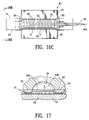
- FIG. 16Cshows the graft body section and shape forming mandrel disposed within the mold cavity (with one half of the mold removed for clarity of illustration) with a fluid being injected into the inflatable channels of the graft body section in order to keep the inflatable channels in an expanded state during the fixing or sintering of the fusible material.
- FIG. 17illustrates an outer layer or layers of fusible material being forced into the mold cavity of a portion of the mold by pressurized fluid as indicated by the dotted line.
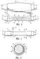
- FIG. 18is an elevational view in partial section of an embodiment of an inflatable endovascular graft of the present invention.
- FIG. 19is an enlarged view of the graft of FIG. 18 taken at the dashed circle indicated by numeral 19 in FIG. 18 .
- FIG. 20is an enlarged view in section taken along lines 20 — 20 in FIG. 18 .
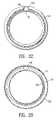
- FIG. 21is a transverse cross sectional view of the graft of FIG. 18 taken along lines 21 — 21 in FIG. 18 .
- FIG. 22is a transverse cross sectional view of the graft of FIG. 18 taken along lines 22 — 22 in FIG. 18 .
- FIG. 23is a transverse cross sectional view of the graft of FIG. 18 taken along lines 23 — 23 in FIG. 18 .
- FIG. 1illustrates a sheet of fusible material 10 stored on an elongate drum 11 .
- the drum 11is rotatable, substantially circular in transverse cross section and has a transverse dimension in the longitudinal center 12 that is greater than the transverse dimension of either end of the drum.
- the sheet of fusible material 10is being rolled from the elongate drum in a single layer 13 onto an interior surface support means in the form of a cylindrical or tapered (conical) shape forming member or mandrel 14 to form a body section 15 of an endovascular graft 16 .
- the body section 15has a proximal end 17 and a distal end 18 .
- the proximal end 17describes the end of the graft that will be oriented towards the oncoming flow of bodily fluid, usually blood, when the device is deployed within a conduit of a patient's body.
- the distal end 18 of the graftis the end opposite the proximal end.
- a single layer of fusible material 13is a term that generally refers to a sheet of material that is not easily separated by mechanical manipulation into additional layers.
- the shape forming mandrel 14is substantially cylindrical in configuration, although other configurations are possible.
- Middle section 20 of mandrel 14 shown in FIGS. 1–2has a transverse dimension which is smaller than the transverse dimension of a first end section 21 and a second end section 22 .
- the shape forming mandrelmay have a first tapered section 23 at the first end and a second tapered section 24 at the second end.
- the sheet of fusible material 10is shown being rolled off the elongate drum 11 in the direction indicated by the arrow 11 A with the lead end 25 of the first layer of fusible material 10 oriented longitudinally along an outside surface 14 A of the shape forming mandrel 14 .
- the fusible material in the embodiment illustrated in FIG. 1is ePTFE that ranges from about 0.0005 to about 0.010 inch in thickness; specifically from about 0.001 to about 0.003 inch in thickness.
- the sheet being disposed or rolled onto the shape forming mandrel 14may range from about 2 to about 10 inches in width; specifically, from about 3 to about 7 inches in width, depending on the indication and size of the end product.
- the ePTFE material sheet 10 in FIG. 1is a fluoropolymer with a node and fibril composition with the fibrils oriented in primarily a uniaxial direction substantially aligned with the longitudinal axis of shape forming mandrel 14 .
- Other nodal/fibril orientations of ePTFEcould also be used for this layer, including multiaxially oriented fibril configurations or uniaxial material oriented substantially circumferentially about shape forming mandrel 14 or at any desired angle between substantial alignment with the longitudinal axis and substantial alignment with a circumferential line about the shape forming mandrel 14 .
- Uniaxially oriented ePTFE materialstend to have greater tensile strength along the direction of fibril orientation, so fibril orientation can be chosen to accommodate the greatest stresses imposed upon the finished product for the particular layer, combination of layers, and portion of the product where such stress accommodation is needed.
- the layers of fusible material made of ePTFEare generally applied or wrapped in an unsintered state.
- the graft body section 15upon completion, can then be sintered or fixed as a whole in order to form a cohesive monolithic structure with all contacting surfaces of ePTFE layers achieving some level of interlayer adhesion. It may, however, be desirable to apply some layers of fusible material that have been pre-sintered or pre-fixed in order to achieve a desired result or to assist in the handling of the materials during the construction process.
- the amount of expansion of the ePTFE material used for the construction of endovascular grafts and other devicescan vary significantly depending on the desired characteristics of the material and the finished product.
- the ePTFE materials processed by the devices and methods discussed hereinmay have a density ranging from about 0.4 to about 2 grams/cc; specifically, from about 0.5 to about 0.9 grams/cc.
- the nodal spacing of the uniaxial ePTFE materialmay range from about 0.5 to about 200 microns; specifically, from about 5 to about 35 microns.
- the nodal spacing for multiaxial ePTFE materialmay range from about 0.5 to about 20 microns; specifically, from about 1 to about 2 microns.
- FIG. 1illustrates a layer of fusible material that is made of ePTFE
- the methods described hereinare also suitable for a variety of other fusible materials.
- suitable fusible materials for endovascular graft construction and other applicationsinclude PTFE, porous PTFE, ultra high molecular weight polyethylene, polyesters, and the like.
- FIGS. 2 and 2Adepict a first layer of fusible material 26 disposed on the shape forming mandrel 14 with an overlapped portion 27 of the first layer 26 on itself.
- a terminal end 28 of the first layer 26is seen extending longitudinally along the length of the shape forming mandrel 14 .
- some tensionmay be provided on the sheet of material by the elongate drum 11 .
- the first layer of material 26conforms closely to the outer contour of the shape forming mandrel 14 as is illustrated in FIG. 2 .
- a seam forming tool or similar device(not shown) along the overlapped portion 27 of first layer 26 in a longitudinal direction in order to form a seam (not shown) along the overlapped portion 27 of first layer 26 .
- a tool suitable for forming such a longitudinal seamis a soldering iron with a smooth, rounded tip that will not catch or tear the layer of fusible material.
- An appropriate operating temperature for the tip of such a toolmay range from about 320 to about 550 degrees Celsius; specifically, from about 380 to about 420 degrees Celsius.
- FIG. 3illustrates an additional layer of fusible material 30 being disposed or wrapped onto the first layer of fusible material 26 in a manner similar to that described above for the first layer 26 .
- Both uniaxial and multiaxial ePTFEmay be used for this additional layer 30 .
- a lead end 31 of the additional layercan be seen adjacent the terminal end 28 of the first layer 26 .
- Tension on the additional layer of fusible material 30helps to make the additional layer 30 conform to the shape forming mandrel 14 as seen in the illustration.
- a single additional layer 30is shown in FIG. 3 as being disposed onto the first layer 26 , it is within the scope of the invention to wrap multiple additional layers 30 of fusible material in this step. We have found that wrapping two additional layers 30 of multiaxial ePTFE onto the first layer 26 helps to form a useful graft body section 15 .
- FIG. 4shows an optional step in which the first and additional layers of fusible material 26 and 30 which form the graft body section 15 under construction are trimmed by knife edge 32 or a similar tool which is pressed against the layers of material and moved circumferentially about the shape forming mandrel 14 .
- FIG. 5is a transverse cross sectional view of the shape forming mandrel 14 and graft body section 15 of FIG. 5 taken along lines 5 — 5 in FIG. 4 .
- the overlapped portion 27 of the first layer 26 and an overlapped portion 33 of the additional layer 30 of fusible materialcan be seen. It may be desirable to create a longitudinal seam in the overlapped portion 33 of the additional layer 30 in a manner similar to that of the first layer 26 discussed above using the same or similar tools.
- FIG. 6illustrates a proximal end wrap 34 of fusible material being applied to the additional layer 30 of graft body section 15 , preferably under some tension.
- end wrap 34be uniaxial ePTFE, with the fibrils of the end wrap material oriented circumferentially about the shape forming mandrel 14 , although other orientations and types of ePTFE are possible.
- the end wrap materialmay have a thickness ranging from about 0.0005 to about 0.005 inch; specifically, from about 0.001 to about 0.002 inch.
- the width of the end wrap materialmay range from about 0.25 to about 2.0 inch; specifically, from about 0.5 to about 1.0 inch.
- One or more layers of end wrap 34may be built up onto the proximal end 17 of graft body section 15 on shape forming mandrel 14 .
- the additional end wrap layer or layers 34may be applied in a manner similar to that of the first layer 26 and additional layers 30 as discussed above.
- FIG. 7shows graft body section 15 with the end wrap layer 34 completed with an inflation line 36 disposed on or near the distal end 18 of graft body section 15 .
- the inflation line 36may be constructed as shown in FIGS. 7A and 7B of ePTFE by wrapping one or more layers of the material about a cylindrical mandrel 37 .
- a longitudinal seam 38can then be formed in an overlapped portion of the layers by passing the tip of a seam forming tool 39 along the overlapped portion of the first layer in a longitudinal direction in order to form a seam 38 along the overlapped portion of the layers of the inflation line 36 .
- a tool suitable for forming such a longitudinal seamis a soldering iron with a smooth rounded tip that will not catch or tear the layer of fusible material; operating temperatures for the tip may range as previously discussed.
- the inflation line 36may be formed using an ePTFE extrusion placed over a mandrel.
- the fusible material of inflation line 36may can be fixed or sintered by heating to a predetermined temperature for a predetermined time.
- the layersare sintered by bringing the layered assembly to a temperature ranging from about 335 to about 380 degrees Celsius (for unsintered material) and about 320 to about 380 degrees Celsius (for sintering material that was previously sintered) and then cooling the assembly to a temperature ranging from about 180 to about 220 degrees Celsius.
- the inflation line 36may then be removed from mandrel 37 and disposed on a graft body assembly 40 as shown in FIG. 7 .
- the inflation line 36may be pre-fixed or pre-sintered to avoid having the inner surfaces of the inflation line 36 stick together during the construction and processing of the graft and possibly block the inflation line 36 .
- proximal connector member 41is an elongate flexible metal element configured as a ring, with the ring having a zig-zag or serpentine pattern around the circumference of the ring.
- the distal connector member 42can have a similar configuration; note the feature of this element in which an extended apex 44 is disposed over inflation line 36 to further stabilize graft section 15 . This configuration allows the connector members 41 and 42 to be radially constrained and radially expanded while maintaining a circular ring configuration.
- the embodiment of the connector members 41 and 42 shown in FIG. 8may be constructed of any suitable biocompatible material; most suitable are metals, alloys, polymers and their composites known to have superelastic properties that allow for high levels of strain without plastic deformation, such as nickel titanium (NiTi). Other alloys such as stainless steel may also be used.
- Connector members 41 and 42 shownare also configured to be self-expanding from a radially constrained state.
- the serpentine pattern of the connector members 41 and 42is disposed over base layers of the graft body section as are connector elements 43 which are disposed on certain apices 44 of the serpentine pattern of the connector members 41 and 42 .
- FIG. 8have been shape formed to lie substantially flat against the contour of the outer surface of the shape forming mandrel 14 .
- FIG. 8illustrates connector members 41 and 42 being disposed upon the graft body section 15 , expandable members including stents or the like may be used in place of the connector members 41 and 42 .
- An optional adhesive or melt-processible materialsuch as FEP or PFA may be deposited adjacent the connector members 41 and 42 prior to the addition of additional layers of fusible material to the graft body section 15 , as is shown in FIG. 9 .
- Materials such as FEP or PFAcan help the layers of fusible material to adhere to the connector members 41 and 42 , to inflation line 36 (in the case of distal member 42 ), and to each other.
- such materialmay serve to provide strain relief between connector members 41 and 42 and the adhered or bonded layers of fusible material (and inflation line 36 ) adjacent the wire of the connector members 41 and 42 .
- the outer overall wrap layer 50may thereafter be applied to the graft body section 15 and connector members 41 and 42 as shown in FIG. 10 .
- the outer overall wrap layer 50can include one, two, three or more layers of multiaxial ePTFE, usually about 2 to about 4 layers, but uniaxial ePTFE other suitable fusible materials, fibril orientation and layer numbers could also be used.
- the outer overall wrap layer 50is most usefully applied under some tension in order for the layer or layers to best conform to the outer contour of the shape forming mandrel 14 and graft body section 15 .
- the outer layer 50comprises multiaxial ePTFE, there is generally no substantially preferred orientation of nodes and fibrils within the microstructure of the material.
- this cuff-reinforcing layeris circumferentially applied to graft body section 15 at or near the graft body section proximal end 17 so to provide additional strength to the graft body section proximal end 17 in those designs in which a proximal cuff (and possibly a proximal rib) are used.
- the graftexperiences larger strains during fabrication and in service in the region of the proximal cuff, especially if a larger cuff is present.
- This optional cuff-reinforcing layertypically is multiaxial ePTFE, although uniaxial ePTFE and other materials may be used as well.
- a cuff-reinforcing layer widthfrom about 20 to about 100 mm; specifically, about 70 mm. Functionally, however, any width sufficient to reinforce the proximal end of graft body section 15 may be used.
- any excess fusible materialmay be trimmed away from the proximal end 17 and distal end 18 of graft body section 15 .
- FIG. 11illustrates one or more layers of fusible material being trimmed from the proximal end 17 and distal end 18 of the graft body section 15 so as to leave the connector members 41 and 42 embedded between layers of fusible material but with the connector elements 43 exposed and a distal end 51 of the inflation line 36 exposed as shown in FIG. 12 .
- an additional processmay optionally be performed on the proximal end 17 , distal end 18 or both the proximal end and distal end 17 and 18 .
- the outer wrap 50is removed from a portion of the connector members 41 and 42 so as to expose a portion of the connector members 41 and 42 and the additional layer of fusible material 30 beneath the connector member 42 and the proximal end wrap 34 beneath connector member 41 .
- one or more layers of the additional layer or layers 30 or proximal end wrap 34may have cuts made therein to form flaps which can be folded back over the respective connector members 42 and 41 and secured to form a joint (not shown).
- One or more layers of fusible materialcan then be disposed over such a joint to provide additional strength and cover up the joint.
- the construction of such a jointis discussed in copending U.S. patent application “Endovascular Graft Joint and Method for Manufacture” by Chobotov et al. which has been incorporated by reference herein.
- This seam forming apparatus 52has a base 53 and a vertical support platform 54 which extends vertically upward from the back edge of the base 53 .
- a mount system 55is secured to the base 53 and for the embodiment shown in the figures, consists of a motor drive chuck unit 56 secured to a riser 57 and a live center unit 58 secured to a riser 59 . Both risers 57 and 59 are secured to the base 53 as shown.
- the axis of rotation 55 A of the chuck 60 of the motor drive chuck unit 56 and the axis of rotation 55 B of the live center 61 of the live center unit 58are aligned or concentric as indicated by dashed line 55 C.
- a motoris mechanically coupled to the chuck 60 of the motor drive chuck unit 56 and serves to rotate the chuck 60 in a controllable manner.
- a vertical translation rack 62is secured to the vertical support platform 54 and extends from the base 53 to the top of the vertical support platform 54 .
- a vertical car 63is slidingly engaged on the vertical translation rack 62 and can be moved along the vertical translation rack 62 , as shown by arrows 63 A, in a controllable manner by a motor and pinion assembly (not shown) secured to the vertical car 63 .
- a horizontal translation rack 64is secured to the vertical car 63 and extends from the left side of the vertical car 63 to the right side of the vertical car 63 .
- a horizontal car 65is slidingly engaged on the horizontal translation rack 64 and can be moved along the horizontal rack 64 , as shown by arrow 64 A, in a controllable manner by a motor and pinion assembly (not shown) which is secured to the horizontal car 65 .
- a stylus rotation unit 66is slidingly engaged with a second horizontal translation rack 65 A disposed on the horizontal car 65 and can be moved towards and away from the vertical car 63 and vertical support platform 54 in a controllable manner as shown by arrow 66 A.
- a stylus rotation shaft 67extends vertically downward from the stylus rotation unit 66 and rotates about an axis as indicated by dashed line 67 B and arrow 67 A in a controllable manner.
- a stylus mount 68is secured to the bottom end of the rotation shaft 67 and has a main body portion 69 and a stylus pivot shaft 70 .
- a stylus housing 71is rotatably secured to the stylus mount 68 by the stylus pivot shaft 70 .
- a torsion spring 72is disposed between the proximal end of the stylus housing 73 and the stylus mount 68 and applies a predetermined amount of compressive, or spring-loaded force to the proximal end 73 of the stylus housing 71 . This in turn determines the amount of tip pressure applied by a distal extremity 80 of a stylus tip 75 disposed at the distal end section 78 of the stylus 79 (which is in turn secured to the distal end section 76 of the stylus housing 71 ).
- the base 53 of seam forming apparatus 52is secured to a control unit housing 77 which contains one or more power supplies, a CPU, and a memory storage unit that are used in an automated fashion to control movement between the graft body 15 section and the stylus tip 75 in the various degrees of freedom therebetween.
- the embodiment of the seam forming apparatus 52 described abovehas five axes of movement (or degrees of freedom) between an object secured to the chuck 60 and live center 61 and the stylus tip 75 ; however, it is possible to have additional axes of movement, such as six, seven, or more. Also, for some configurations and seam forming processes, it may be possible to use fewer axes of movement, such as two, three, or four.
- any number of configurationsmay be used to achieve the desired number of degrees of freedom between the stylus 79 and the mounted device.
- additional axes of translation or rotationcould be added to the mount system and taken away from the stylus rotation unit 66 .
- the embodiment of the shape forming mandrel 14 shown in FIGS. 1–17is cylindrical, a five axis or six axis seam forming apparatus has the capability and versatility to accurately create seams of most any desired configuration on a shape forming member or mandrel of a wide variety of shapes and sizes.
- a “Y” shaped mandrel suitable for generating a bifurcated graft body sectioncould be navigated by the five axis seam forming apparatus illustrated herein, as well as other shapes.
- seam forming apparatus 52 illustrated hereinis but one of a number of devices and configurations capable of achieving the seams of the present inventions.
- FIG. 13Dillustrates an enlarged view of a stylus tip 75 applied to a rotating cylindrical surface 86 B with the surface rotating in a counterclockwise direction as indicated by arrow 86 A.
- the cylindrical surfacecan support one or more layers of fusible material (not shown) between the distal extremity 80 of the stylus tip 75 and the surface 86 B which require seam to be formed therein.
- the stylus tip 75has a longitudinal axis that forms an angle 86 with a tangent to the surface of the cylindrical surface indicated by dashed line 87 .
- angle 86may range from about 5 to about 60 degrees; specifically, from about 10 to about 20 degrees. It is also useful if the distal extremity 80 of the stylus tip 75 has a smooth surface and is radiused. A suitable radius for one embodiment may range from about 0.01 to about 0.030 inch; specifically, from about 0.015 to about 0.02 inch.
- FIG. 13Eshows a similar relationship between a stylus tip 75 and hard surface 81 .
- Surface 81may have one or more layers of fusible material (not shown) disposed thereon between distal extremity 80 and surface 81 .
- a longitudinal axis 75 A of stylus tip 75forms an angle 86 with the dashed line 89 that is parallel to surface 81 .
- Angle 88 in this embodimentshould range from about 5 to about 60 degrees; specifically, from about 10 to about 20 degrees, so to ensure smooth relative motion between surface 81 and tip 75 .
- the surface 81is shown moving relative to the stylus tip 75 in the direction indicated by arrow 81 A.
- the pressure exerted by the extremity 80 of stylus tip 75 on the material being processedis another parameter that can affect the quality of a seam formed in layers of fusible material.
- the pressure exerted by the distal extremity 80 of the stylus tip 75may range from about 100 to about 6,000 pounds per square inch (psi); specifically, from about 300 to about 3,000 psi.
- the speed of the heated stylus 75 relative to the material being processed, such as that of graft body section 15may range from about 0.2 to about 10 mm per second, specifically, from about 0.5 to about 1.5 mm per second.
- the temperature of the distal extremity 80 of the heated stylus tip 75 in this embodimentmay range from about 320 to about 550 degrees Celsius; specifically, about 380 to about 420 degrees Celsius.
- Seam formation for ePTFEnormally occurs by virtue of the application of both heat and pressure.
- the temperatures at the tip of the heated stylus 75 during such seam formationare generally above the melting point of highly crystalline ePTFE, which may range be from about 327 to about 340 degrees Celsius, depending in part on whether the material is virgin material or has previously been sintered).
- the stylus tip temperature for ePTFE welding and seam formationis about 400 degrees Celsius. Pressing such a heated tip 75 into the layers of ePTFE against a hard surface such as the outside surface of the shape forming mandrel) compacts and heats the adjacent layers to form a seam with adhesion between at least two of, if not all, the layers.
- the ePTFEAt the seam location and perhaps some distance away from the seam, the ePTFE generally transforms from an expanded state with a low specific gravity to a non-expanded state (i.e., PTFE) with a relatively high specific gravity.
- PTFEnon-expanded state
- Some meshing and entanglement of nodes and fibrils of adjacent layers of ePTFEmay occur and add to the strength of the seam formed by thermal-compaction.
- the overall result of a well-formed seam between two or more layers of ePTFEis adhesion that can be nearly as strong or as strong as the material adjacent the seam.
- the microstructure of the layersmay change in the seam vicinity such that the seam will be impervious to fluid penetration.
- Such parametersinclude, but are not limited to, the time the stylus tip 75 is in contact with the material (or for continuous seams, the rate of tip movement), the temperature (of the tip extremity 80 as well as that of the material, the underlying surface 81 , and the room), tip contact pressure, the heat capacity of the material, the mandrel, and the other equipment, the characteristics of the material (e.g. the node and fibril spacing, etc.), the number of material layers present, the contact angle between the tip extremity 80 and the material, the shape of the extremity 80 , etc.
- a useful seammay be formed by pressure at ambient temperature (followed by elevation to sintering temperature); likewise, a useful seam may also be formed by elevated temperature and little-to-no applied pressure.
- seams in ePTFEthat formed an intact, inflatable cuff by the use of a clamshell mold that presented an interference fit on either side of a cuff zone for the ePTFE.
- the application of pressure alone without using an elevated temperature prior to sinteringformed a seam sufficient to create a working cuff.
- FIG. 13Fdepicts a front view of the seam forming apparatus 52 with a shape forming mandrel 14 secured to the chuck 60 and the live center unit 58 .
- the distal extremity of the heated stylus tip 75is in contact with the graft body section 15 which is disposed on the shape forming mandrel 14 .
- the chuck 60is turning the shape forming mandrel 14 and graft body section 15 in the direction indicated by the arrow 60 A to form a seam 81 between the layers of fusible material of the graft body section 15 .
- FIGS. 13G and 13Hillustrate an enlarged view of the heated stylus tip 75 in contact with the graft body section 15 in the process of creating one ore more seams 81 which are configured to form elongate inflatable channels 82 in the graft body section 15 .
- the term “inflatable channels”may generally be described herein as a substantially enclosed or enclosed volume between layers of fusible material on a graft or graft section, and in some embodiments, in fluid communication with at least one inlet port for injection of inflation material.
- the enclosed volume of an inflatable channel or cuffmay be zero if the inflatable cuff or channel is collapsed in a non-expanded state.
- the enclosed volume of an inflatable channelmay or may not be collapsible during compression or compacting of the graft body section 15 .
- FIG. 13His an enlarged view in section of the distal extremity 80 of the heated stylus tip 75 in contact with layers of fusible material of graft body section 15 .
- the layers of fusible materialare being heated and compressed to form a bond 15 A therebetween.
- the seam forming apparatuscan position the distal extremity 80 at any desired location on the graft body section 15 by activation of one or more of the five motors controlled by the components in the control unit housing 77 .
- Each of the five motorscontrols relative movement between graft body section 15 and distal extremity 80 in one degree of freedom.
- the distal extremity 80may be positioned above the surface of the graft body section 15 , as shown in FIG.
- extremity 80Once extremity 80 has reached the target temperature, it can be lowered by activation of the motor which controls movement of the vertical car. The extremity 80 can be lowered and horizontally positioned by other control motors until it contacts the graft body section in a desired predetermined position on graft body section 15 , as shown in FIG. 13F .
- distal extremity 80makes contact with graft body section 15 with the proper amount of pressure, it begins to form a seam between the layers of the fusible material of the graft body section as shown in FIG. 13H .
- the pressure or force exerted by the extremity 80 on the graft body sectionmay be determined by the spring constant and amount of deflection of torsion spring 72 shown in FIGS. 13A and 13B ; generally, we have found a force at the extremity 80 ranging from about 0.2 to about 100 grams to be useful.
- the surface of graft body section 15may be translated with respect to the distal extremity 80 while desirably maintaining a fixed, predetermined amount of pressure between the distal extremity 80 and the layers of fusible material of the graft body section.
- the CPU (or an equivalent device capable of controlling the components of apparatus 52 ) of the control unit housing 77may be programmed, for instance, a mathematical representation of the outer surface contour of any known shape forming member or mandrel.
- the CPUis thereby able to control movement of the five motors of apparatus 52 , so that distal extremity 80 may follow the contour of the shape forming member while desirably exerting a fixed predetermined amount of pressure the layers of fusible material disposed between the distal extremity 80 and the shape forming member. While seam formation is taking place, the pressure exerted by the distal extremity 80 on the shape forming member may be adjusted dynamically.
- the extremity 80may also be lifted off the graft body section and shape forming member in locations where there is a break in the desired seam pattern. Once distal extremity 80 is positioned above the location of the starting point of the next seam following the break, the extremity 80 may then be lowered to contact the layers of fusible material, reinitiating the seam formation process.
- seam forming apparatus 52is but one of a number of ways to create the desired seams in the graft body section 15 of the present invention. Any suitable process and apparatus may be used as necessary and the invention is not so limited. For instance, seams may also be formed in a graft body section 15 by the use of a fully or partially heated clamshell mold whose inner surfaces contain raised seam-forming extensions.
- extensionsmay be configured and preferentially or generally heated so that when the mold halves are closed over a graft body section 15 disposed on a mandrel, the extensions apply heat and pressure to the graft body section directly under the extensions, thereby “branding” a seam in the graft body section in any pattern desired and in a single step, saving much time over the technique described above in conjunction with seam forming apparatus 52 .
- the fusible materialcomprises ePTFE
- an adhesivesuch as FEP or PFA
- PFAadhesive
- Curing or drying this adhesive materialwill mechanically lock the ePTFE layers together through a continuous or semi-continuous network of adhesive material now present in and between the ePTFE layers, effectively bonding the layers together.
- FIG. 14illustrates a substantially completed set of seams 81 formed in the layers of fusible material of the graft body section 15 , which seams form inflatable channels 82 .
- FIG. 15illustrates graft body section 15 as fluid (such as compressed gas) is injected into the inflation line 36 and in turn into the inflatable channel network 84 of body section 15 , as shown by arrow 84 A. The fluid is injected to pre-stress the inflatable channels 82 of body section 15 and expand them outward radially. The fluid may be delivered or injected through an optional elongate gas containment means having means for producing a permeability gradient in the form of a manifold or pressure line 85 .
- 15has a configuration with an input (not shown) located outside the inflation line and a plurality of outlet apertures or orifices (not shown) that may be configured to provide an even distribution of pressure within the inflatable channel network 84 .
- Other fluid injection schemes and configurationsare of course possible.
- pressure line 85may comprise apertures or orifices (not shown) which, when disposed in graft body section 15 , progressively increases in size as one moves distally along the pressure line towards the proximal end 17 graft body section 15 in order to compensate for a drop in pressure both within the inflatable channel network 84 and within the manifold or pressure line 85 itself.
- the graft body section 15 and shape forming mandrel assembly 89may then be positioned within an outer constraint means in the form of a mold to facilitate the inflatable channel expansion and sintering process.
- One half of a mold 90 suitable for forming an embodiment of a graft body section 15 such as that shown in FIG. 15is illustrated in FIG. 16A .
- a mold half body portion 91is one of two pieces of mold 90 .
- a mold similar to mold 90could be made from any number of mold body portions configured to fit together.
- a mold 90could be designed from three, four, five or more mold body portions configured to fit together to form a suitable main cavity portion 93 for maintaining the shape of graft body section 15 during channel expansion and sintering.
- a one-piece moldmay be used.
- Mold body portion 91has a contact surface 92 and a main cavity portion 93 .
- Main cavity portion 93has an inside surface contour configured to match an outside surface contour of the graft body section with the inflatable channels in an expanded state.
- Optional exhaust channels 92 Amay be formed in contact surface 92 and provide an escape flow path for pressurized gas injected into the inflatable channel network 84 during expansion of the inflatable channels 82 .
- the main cavity portion 93 of the FIGS. 16A–16B embodimentis substantially in the shape of a half cylinder with circumferential channel cavities 94 for forming the various inflatable channels 82 of graft body section 15 .
- Cavity 93has a first tapered portion 95 at the proximal end 96 of mold 90 and a second tapered portion 97 at the mold distal end 98 .
- FIG. 16Bshows an end view of mold 90 with the two mold body portions 91 and 100 pressed together with the assembly of the graft body section 15 and shape forming mandrel 14 disposed mold cavity 93 .
- FIG. 16Cshows the assembly of the graft body section 15 and shape forming mandrel 14 disposed within mold 90 , with the circumferential inflatable channels 82 of the graft body section 15 aligned with the circumferential channel cavities 94 of the main cavity portion 93 .
- One mold body portion 100 of mold 90is not shown for the purpose of clarity of illustration.
- FIG. 17illustrates by the phantom lines how the outer layers 94 A of circumferential inflatable channel 82 of the fusible material of a graft body section 15 are expanded into the circumferential channel cavity 94 of mold cavity 93 .
- the direction of the expansion of the outer layers 94 A to the position indicated by the phantom linesis indicated by arrow 94 B.
- a cross sectional view of the seams 83 of the circumferential inflatable channel 82is shown in FIG. 17 as well.
- the entire assemblymay be positioned within an oven or other heating device (not shown) in order to bring the fusible material of graft body section 15 to a suitable temperature for an appropriate amount of time in order to fix or sinter the fusible material.
- the fusible materialis ePTFE and the sintering process is carried out by bringing the fusible material to a temperature of between about 335 and about 380 degrees Celsius; specifically, between about 350 and about 370 degrees Celsius.
- the moldmay then be cooled and optionally quenched until the temperature of the mold drops to about 250 degrees Celsius.
- the moldmay optionally further be quenched (for handling reasons) with ambient temperature fluid such as water. Thereafter, the two halves 91 and 100 of mold 90 can be pulled apart, and the graft assembly removed.
- mold 90to facilitate the inflatable channel expansion and sintering process is unique in that the mold cavity portion 93 acts as a backstop to the graft body section so that during sintering, the pressure created by the injected fluid that tends to expand the inflatable channels outward is countered by the restricting pressure exerted by the physical barrier of the surfaces defining the mold cavity 93 . In general terms, therefore, it is the pressure differential across the inflatable channel ePTFE layers that in part defines the degree of expansion of the channels during sintering.
- the external pressure exerted by the mold cavity surfacecompetes with the fluid pressure internal to the inflatable channels (kept at a level to counteract any leakage of fluid through the ePTFE pores at sintering temperatures) to provide an optimal pressure differential across the ePTFE membrane(s) to limit and define the shape and size of the inflatable channels.
- the network of inflatable channels 84can also be expanded during the fixation process or sintering process by use of vapor pressure from a fluid disposed within the network of inflatable channels 84 .
- the network of inflatable channels 84can be filled with water or a similar fluid prior to positioning assembly in the oven, as discussed above. As the temperature of the graft body section 15 and network of inflatable channels 84 begins to heat, the water within the network of inflatable channels 84 begins to heat and eventually boil. The vapor pressure from the boiling water within the network of inflatable channels 84 will expand the network of inflatable channels 84 provided the vapor is blocked at the inflation line 85 or otherwise prevented from escaping the network of inflatable channels.
- FIG. 18shows an elevational view in partial longitudinal section of an endovascular graft assembly 105 manufactured by the methods and with the apparatus described above.
- Endovascular graft assembly 105comprises a graft body section 108 with a proximal end 106 , a distal end 107 , and circumferentially oriented inflatable channels 111 shown in an expanded state.
- a longitudinal inflatable channel 116fluidly communicates with the circumferential inflatable channels 111 .
- An expandable member in the form of a proximal connector member 112is shown embedded between proximal end wrap layers 113 of fusible material.
- An expandable member in the form of a distal connector member 114is likewise shown embedded between distal end wrap layers 115 of fusible material.
- the proximal connector member 112 and distal connector member 114 of this embodimentare configured to be secured or connected to other expandable members which may include stents or the like, which are not shown. In the embodiment of FIG. 18 , such a connection may be accomplished via connector elements 117 of the proximal and distal connector members 112 and 114 , which extend longitudinally outside of the proximal and distal end wrap layers 113 and 115 away from the graft body section 108 .
- the FIG. 18 embodiment of the present inventionfeatures junction 118 between the distal end wrap layers 115 of fusible material and the layers of fusible material of a distal end 121 of the graft assembly main body portion 122 .
- junction 123between the proximal end wrap layers 113 and the layers of fusible material of a proximal end 124 of the graft assembly main body portion 122 .
- the junctions 118 and 123may be tapered, with overlapping portions that are bound by sintering or thermomechanical compaction of the end wrap layers 113 and 115 and layers of the main body portion 122 . This junction 123 is shown in more detail in FIG. 19 .
- proximal end wrap fusible material layers 113are disposed between three fusible material inner layers 125 and three fusible material outer layers 126 of the main body portion proximal end 124 .
- FIG. 20illustrates a sectional view of a portion of the distal connector member 114 disposed within the distal end wrap layers 115 of fusible material.
- Connector member 114is disposed between three outer layers 127 of fusible material and three inner layers 128 of fusible material.
- Optional seams 127 Aformed by the methods discussed above, are disposed on either side of distal connector member 114 and mechanically capture the connector member 114 .
- FIG. 21likewise is a transverse cross sectional view of the proximal connector member 112 embedded in the proximal end wrap layers 113 of fusible material.
- FIG. 22illustrates a transverse cross section of the longitudinal inflatable channel 116 formed between main body portion 122 outer layers 131 and the main body portion 122 inner layers 132 .
- FIG. 23is a transverse cross section of graft main body portion 122 showing a circumferential inflatable channel 111 in fluid communication with longitudinal inflatable channel 116 .
- the circumferential inflatable channel 111is formed between the outer layers 131 of fusible material of main body portion 122 and inner layers 132 of fusible material of main body portion 122 .
Landscapes
- Engineering & Computer Science (AREA)
- Mechanical Engineering (AREA)
- Physics & Mathematics (AREA)
- Thermal Sciences (AREA)
- Health & Medical Sciences (AREA)
- High Energy & Nuclear Physics (AREA)
- Biomedical Technology (AREA)
- Life Sciences & Earth Sciences (AREA)
- Oral & Maxillofacial Surgery (AREA)
- Transplantation (AREA)
- Pulmonology (AREA)
- Heart & Thoracic Surgery (AREA)
- Vascular Medicine (AREA)
- Cardiology (AREA)
- Animal Behavior & Ethology (AREA)
- General Health & Medical Sciences (AREA)
- Public Health (AREA)
- Veterinary Medicine (AREA)
- Gastroenterology & Hepatology (AREA)
- Plasma & Fusion (AREA)
- Prostheses (AREA)
Abstract
Description
Claims (20)
Priority Applications (14)
| Application Number | Priority Date | Filing Date | Title |
|---|---|---|---|
| US10/029,557US7125464B2 (en) | 2001-12-20 | 2001-12-20 | Method for manufacturing an endovascular graft section |
| ES02805657TES2340575T3 (en) | 2001-12-20 | 2002-12-20 | PROCEDURE AND MANUFACTURING DEVICE OF A SECTION OF AN ENDOVASCULAR GRAFT. |
| CA002468969ACA2468969A1 (en) | 2001-12-20 | 2002-12-20 | Method and apparatus for manufacturing an endovascular graft section |
| AU2002366805AAU2002366805B8 (en) | 2001-12-20 | 2002-12-20 | Method and apparatus for manufacturing an endovascular graft section |
| AT02805657TATE460902T1 (en) | 2001-12-20 | 2002-12-20 | METHOD AND DEVICE FOR PRODUCING AN ENDOVASCULAR TRANSPLANT SECTION |
| EP02805657AEP1465685B1 (en) | 2001-12-20 | 2002-12-20 | Method and apparatus for manufacturing an endovascular graft section |
| JP2003554251AJP2005512687A (en) | 2001-12-20 | 2002-12-20 | Method and apparatus for producing an endovascular graft section |
| DE60235723TDE60235723D1 (en) | 2001-12-20 | 2002-12-20 | METHOD AND DEVICE FOR PRODUCING AN ENDOVASCULAR TRANSPLANT SECTION |
| PCT/US2002/040997WO2003053495A2 (en) | 2001-12-20 | 2002-12-20 | Method and apparatus for manufacturing an endovascular graft section |
| US11/522,490US7678217B2 (en) | 2001-12-20 | 2006-09-15 | Method for manufacturing an endovascular graft section |
| AU2008258148AAU2008258148B2 (en) | 2001-12-20 | 2008-12-17 | Method and apparatus for manufacturing an endovascular graft section |
| JP2009170917AJP5149252B2 (en) | 2001-12-20 | 2009-07-22 | Method and apparatus for producing endovascular graft sections |
| US12/697,504US8783316B2 (en) | 2001-12-20 | 2010-02-01 | Apparatus for manufacturing an endovascular graft section |
| JP2012184952AJP5513567B2 (en) | 2001-12-20 | 2012-08-24 | Method and apparatus for producing endovascular graft sections |
Applications Claiming Priority (1)
| Application Number | Priority Date | Filing Date | Title |
|---|---|---|---|
| US10/029,557US7125464B2 (en) | 2001-12-20 | 2001-12-20 | Method for manufacturing an endovascular graft section |
Related Child Applications (1)
| Application Number | Title | Priority Date | Filing Date |
|---|---|---|---|
| US11/522,490DivisionUS7678217B2 (en) | 2001-12-20 | 2006-09-15 | Method for manufacturing an endovascular graft section |
Publications (2)
| Publication Number | Publication Date |
|---|---|
| US20030116260A1 US20030116260A1 (en) | 2003-06-26 |
| US7125464B2true US7125464B2 (en) | 2006-10-24 |
Family
ID=21849637
Family Applications (3)
| Application Number | Title | Priority Date | Filing Date |
|---|---|---|---|
| US10/029,557Expired - LifetimeUS7125464B2 (en) | 2001-12-20 | 2001-12-20 | Method for manufacturing an endovascular graft section |
| US11/522,490Expired - Fee RelatedUS7678217B2 (en) | 2001-12-20 | 2006-09-15 | Method for manufacturing an endovascular graft section |
| US12/697,504Expired - Fee RelatedUS8783316B2 (en) | 2001-12-20 | 2010-02-01 | Apparatus for manufacturing an endovascular graft section |
Family Applications After (2)
| Application Number | Title | Priority Date | Filing Date |
|---|---|---|---|
| US11/522,490Expired - Fee RelatedUS7678217B2 (en) | 2001-12-20 | 2006-09-15 | Method for manufacturing an endovascular graft section |
| US12/697,504Expired - Fee RelatedUS8783316B2 (en) | 2001-12-20 | 2010-02-01 | Apparatus for manufacturing an endovascular graft section |
Country Status (1)
| Country | Link |
|---|---|
| US (3) | US7125464B2 (en) |
Cited By (54)
| Publication number | Priority date | Publication date | Assignee | Title |
|---|---|---|---|---|
| WO2003053288A1 (en) | 2001-12-20 | 2003-07-03 | Trivascular, Inc. | Advanced endovascular graft |
| US20080015687A1 (en)* | 2004-05-05 | 2008-01-17 | Direct Flow Medical, Inc. | Method of in situ formation of translumenally deployable heart valve support |
| US20110218609A1 (en)* | 2010-02-10 | 2011-09-08 | Trivascular, Inc. | Fill tube manifold and delivery methods for endovascular graft |
| US8034100B2 (en) | 1999-03-11 | 2011-10-11 | Endologix, Inc. | Graft deployment system |
| US8066755B2 (en) | 2007-09-26 | 2011-11-29 | Trivascular, Inc. | System and method of pivoted stent deployment |
| US8083789B2 (en) | 2007-11-16 | 2011-12-27 | Trivascular, Inc. | Securement assembly and method for expandable endovascular device |
| US8118856B2 (en) | 2009-07-27 | 2012-02-21 | Endologix, Inc. | Stent graft |
| US8167925B2 (en) | 1999-03-11 | 2012-05-01 | Endologix, Inc. | Single puncture bifurcation graft deployment system |
| US8226701B2 (en) | 2007-09-26 | 2012-07-24 | Trivascular, Inc. | Stent and delivery system for deployment thereof |
| US8236040B2 (en) | 2008-04-11 | 2012-08-07 | Endologix, Inc. | Bifurcated graft deployment systems and methods |
| US8241346B2 (en) | 2001-12-20 | 2012-08-14 | Trivascular, Inc. | Endovascular graft and method of delivery |
| US8328861B2 (en) | 2007-11-16 | 2012-12-11 | Trivascular, Inc. | Delivery system and method for bifurcated graft |
| US8491646B2 (en) | 2009-07-15 | 2013-07-23 | Endologix, Inc. | Stent graft |
| US8523931B2 (en) | 2007-01-12 | 2013-09-03 | Endologix, Inc. | Dual concentric guidewire and methods of bifurcated graft deployment |
| WO2013151793A1 (en) | 2012-04-06 | 2013-10-10 | Trivascular, Inc. | Low profile stent graft and delivery system |
| WO2013151794A2 (en) | 2012-04-03 | 2013-10-10 | Trivascular, Inc. | Advanced kink-resistant stent graft |
| US8556881B2 (en) | 2006-10-19 | 2013-10-15 | Direct Flow Medical, Inc. | Catheter guidance through a calcified aortic valve |
| US8568477B2 (en) | 2005-06-07 | 2013-10-29 | Direct Flow Medical, Inc. | Stentless aortic valve replacement with high radial strength |
| US20130305512A1 (en)* | 2012-05-18 | 2013-11-21 | Abbott Cardiovascular Systems, Inc. | Apparatus and methods for forming medical devices |
| WO2013188132A1 (en) | 2012-06-15 | 2013-12-19 | Trivascular, Inc. | Endovascular delivery system with an improved radiopaque marker scheme |
| WO2013188133A1 (en) | 2012-06-15 | 2013-12-19 | Trivascular, Inc. | Endovascular delivery system with flexible and torqueable hypotube |
| WO2013188134A1 (en) | 2012-06-15 | 2013-12-19 | Trivascular, Inc. | Bifurcated endovascular prosthesis having tethered contralateral leg |
| US8663309B2 (en) | 2007-09-26 | 2014-03-04 | Trivascular, Inc. | Asymmetric stent apparatus and method |
| US20140082924A1 (en)* | 2008-01-07 | 2014-03-27 | DePuy Synthes Products, LLC | Radiopaque super-elastic intravascular stent |
| WO2014059114A2 (en) | 2012-10-10 | 2014-04-17 | Trivascular, Inc. | Endovascular graft for aneurysms involving major branch vessels |
| WO2014110254A1 (en) | 2013-01-10 | 2014-07-17 | Trivascular, Inc. | Gate wire for contralateral leg access |
| US8808350B2 (en) | 2011-03-01 | 2014-08-19 | Endologix, Inc. | Catheter system and methods of using same |
| US8945202B2 (en) | 2009-04-28 | 2015-02-03 | Endologix, Inc. | Fenestrated prosthesis |
| US8978448B2 (en) | 2011-10-11 | 2015-03-17 | Trivascular, Inc. | In vitro testing of endovascular device |
| US8992595B2 (en) | 2012-04-04 | 2015-03-31 | Trivascular, Inc. | Durable stent graft with tapered struts and stable delivery methods and devices |
| WO2015048004A1 (en) | 2013-09-24 | 2015-04-02 | Trivascular, Inc. | Tandem modular endograft |
| WO2015138402A1 (en) | 2014-03-10 | 2015-09-17 | Trivascular, Inc. | Inflatable occlusion wire-balloon for aortic applications |
| US9308360B2 (en) | 2007-08-23 | 2016-04-12 | Direct Flow Medical, Inc. | Translumenally implantable heart valve with formed in place support |
| US9393100B2 (en) | 2010-11-17 | 2016-07-19 | Endologix, Inc. | Devices and methods to treat vascular dissections |
| US9433501B2 (en) | 2010-05-19 | 2016-09-06 | Direct Flow Medical, Inc. | Inflation media for implants |
| US9445897B2 (en) | 2012-05-01 | 2016-09-20 | Direct Flow Medical, Inc. | Prosthetic implant delivery device with introducer catheter |
| US9463101B2 (en) | 2012-04-06 | 2016-10-11 | Trivascular, Inc. | Low profile stent and delivery system |
| US9498363B2 (en) | 2012-04-06 | 2016-11-22 | Trivascular, Inc. | Delivery catheter for endovascular device |
| US9572661B2 (en) | 2006-10-19 | 2017-02-21 | Direct Flow Medical, Inc. | Profile reduction of valve implant |
| US9579103B2 (en) | 2009-05-01 | 2017-02-28 | Endologix, Inc. | Percutaneous method and device to treat dissections |
| US9603708B2 (en) | 2010-05-19 | 2017-03-28 | Dfm, Llc | Low crossing profile delivery catheter for cardiovascular prosthetic implant |
| US9655754B2 (en) | 2013-01-10 | 2017-05-23 | Trivascular, Inc. | Systems and methods for guidewire crossover for bifurcated prostheses |
| US9700701B2 (en) | 2008-07-01 | 2017-07-11 | Endologix, Inc. | Catheter system and methods of using same |
| US9956101B2 (en) | 2014-12-04 | 2018-05-01 | Trivascular, Inc. | Internal iliac preservation devices and methods |
| US10064626B2 (en)* | 2015-08-13 | 2018-09-04 | The Brain Protection Company PTY LTD | Implantable damping devices for treating dementia and associated systems and methods of use |
| EP3409243A1 (en) | 2014-01-09 | 2018-12-05 | TriVascular, Inc. | Systems for guidewire crossover for bifurcated prostheses |
| US10159557B2 (en) | 2007-10-04 | 2018-12-25 | Trivascular, Inc. | Modular vascular graft for low profile percutaneous delivery |
| US10245166B2 (en) | 2008-02-22 | 2019-04-02 | Endologix, Inc. | Apparatus and method of placement of a graft or graft system |
| US10653510B2 (en) | 2016-11-09 | 2020-05-19 | Boston Scientific Scimed, Inc. | Stent including displacement capabilities |
| US10772717B2 (en) | 2009-05-01 | 2020-09-15 | Endologix, Inc. | Percutaneous method and device to treat dissections |
| US11129737B2 (en) | 2015-06-30 | 2021-09-28 | Endologix Llc | Locking assembly for coupling guidewire to delivery system |
| US11406518B2 (en) | 2010-11-02 | 2022-08-09 | Endologix Llc | Apparatus and method of placement of a graft or graft system |
| US11786355B2 (en) | 2020-01-30 | 2023-10-17 | Boston Scientific Scimed, Inc. | Radial adjusting self-expanding stent with anti-migration features |
| US12208027B2 (en) | 2018-12-04 | 2025-01-28 | The Brain Protection Company PTY LTD | Combinatorial therapies including implantable damping devices and therapeutic agents for treating a condition and associated systems and methods of use |
Families Citing this family (17)
| Publication number | Priority date | Publication date | Assignee | Title |
|---|---|---|---|---|
| US20040138734A1 (en)* | 2001-04-11 | 2004-07-15 | Trivascular, Inc. | Delivery system and method for bifurcated graft |
| US7560006B2 (en) | 2001-06-11 | 2009-07-14 | Boston Scientific Scimed, Inc. | Pressure lamination method for forming composite ePTFE/textile and ePTFE/stent/textile prostheses |
| AU2003299946A1 (en)* | 2002-12-30 | 2004-07-29 | Morsi Hesham | Endovascular balloon graft |
| US7150758B2 (en)* | 2003-03-06 | 2006-12-19 | Boston Scientific Santa Rosa Corp. | Kink resistant endovascular graft |
| US7530994B2 (en)* | 2003-12-30 | 2009-05-12 | Scimed Life Systems, Inc. | Non-porous graft with fastening elements |
| US7727271B2 (en)* | 2004-06-24 | 2010-06-01 | Boston Scientific Scimed, Inc. | Implantable prosthesis having reinforced attachment sites |
| US20060233991A1 (en) | 2005-04-13 | 2006-10-19 | Trivascular, Inc. | PTFE layers and methods of manufacturing |
| US8221486B2 (en)* | 2006-11-21 | 2012-07-17 | Boston Scientific Scimed, Inc. | Laminated stent graft edge binding |
| FR2915903B1 (en)* | 2007-05-10 | 2010-06-04 | Carpentier Matra Carmat | METHOD FOR THE PRODUCTION OF A HEMOCOMPATIBLE OBJECT OF COMPLEX CONFIGURATION AND OBJECT THUS OBTAINED |
| US20090082841A1 (en)* | 2007-09-26 | 2009-03-26 | Boston Scientific Corporation | Apparatus for securing stent barbs |
| US20100331958A1 (en)* | 2007-12-20 | 2010-12-30 | Trivascular, Inc. | Hinged endovascular device |
| US9433991B2 (en) | 2011-12-21 | 2016-09-06 | Edwards Lifesciences Corporation | Apparatus and method for stent shaping |
| US11114918B2 (en)* | 2013-06-26 | 2021-09-07 | Corindus, Inc. | Differential drive |
| WO2015119721A1 (en)* | 2014-02-07 | 2015-08-13 | C. R. Bard, Inc. | Eptfe valves |
| US10166126B2 (en) | 2014-12-08 | 2019-01-01 | Boston Scientific Scimed, Inc. | Inflatable balloon stent |
| CN107530162B (en) | 2015-05-11 | 2020-01-24 | 曲瓦斯库勒股份有限公司 | Stent graft with improved flexibility |
| EP3648705A4 (en) | 2017-07-07 | 2021-03-24 | Endologix LLC | Endovascular graft systems and methods for deployment in main and branch arteries |
Citations (201)
| Publication number | Priority date | Publication date | Assignee | Title |
|---|---|---|---|---|
| US1324850A (en) | 1919-12-16 | roberts | ||
| US2372917A (en) | 1941-07-01 | 1945-04-03 | Tuttle Wainwright | Apparatus for producing corrugated tubing |
| US2983961A (en) | 1957-01-30 | 1961-05-16 | Resistoflex Corp | Blow molding of polytetrafluoroethylene |
| US3631854A (en) | 1969-05-19 | 1972-01-04 | Robert Howard Fryer | Inflatable medical assemblies |
| US3991767A (en) | 1973-11-02 | 1976-11-16 | Cutter Laboratories, Inc. | Tubular unit with vessel engaging cuff structure |
| US4049762A (en) | 1973-08-03 | 1977-09-20 | Harsco Corporation | Method of forming a pipe coupling |
| US4183102A (en) | 1977-09-08 | 1980-01-15 | Jacques Guiset | Inflatable prosthetic device for lining a body duct |
| US4201144A (en) | 1977-04-15 | 1980-05-06 | Toshiba Kikai Kabushiki Kaisha | Control systems for automatic sewing machines |
| US4218420A (en) | 1979-04-18 | 1980-08-19 | Dayco Corporation | Hose curing method |
| US4229838A (en) | 1977-07-01 | 1980-10-28 | Sumitomo Electric Industries, Ltd. | Vascular prosthesis having a composite structure |
| US4319872A (en) | 1976-12-01 | 1982-03-16 | Lupke Gerd Paul Heinrich | Apparatus for producing thermoplastic tubing |
| US4386566A (en) | 1980-10-06 | 1983-06-07 | Mosstype Corporation | Mandrel assembly for demountable printing cylinder |
| US4434797A (en) | 1979-01-12 | 1984-03-06 | Ab Tesi | Catheter |
| US4481323A (en)* | 1980-05-07 | 1984-11-06 | Medical Research Associates, Ltd. #2 | Hydrocarbon block copolymer with dispersed polysiloxane |
| US4482516A (en) | 1982-09-10 | 1984-11-13 | W. L. Gore & Associates, Inc. | Process for producing a high strength porous polytetrafluoroethylene product having a coarse microstructure |
| US4580568A (en) | 1984-10-01 | 1986-04-08 | Cook, Incorporated | Percutaneous endovascular stent and method for insertion thereof |
| US4655769A (en) | 1984-10-24 | 1987-04-07 | Zachariades Anagnostis E | Ultra-high-molecular-weight polyethylene products including vascular prosthesis devices and methods relating thereto and employing pseudo-gel states |
| US4705517A (en) | 1985-09-03 | 1987-11-10 | Becton, Dickinson And Company | Percutaneously deliverable intravascular occlusion prosthesis |
| US4731073A (en) | 1981-02-13 | 1988-03-15 | Thoratec Laboratories Corporation | Arterial graft prosthesis |
| US4732629A (en) | 1986-07-25 | 1988-03-22 | Cooper Peter B | Method for manufacturing an insulated conductor having a high cut-through resistance |
| US4941870A (en) | 1986-11-10 | 1990-07-17 | Ube-Nitto Kasei Co., Ltd. | Method for manufacturing a synthetic vascular prosthesis |
| US4957669A (en) | 1989-04-06 | 1990-09-18 | Shiley, Inc. | Method for producing tubing useful as a tapered vascular graft prosthesis |
| US5122154A (en) | 1990-08-15 | 1992-06-16 | Rhodes Valentine J | Endovascular bypass graft |
| US5151105A (en) | 1991-10-07 | 1992-09-29 | Kwan Gett Clifford | Collapsible vessel sleeve implant |
| US5156620A (en) | 1991-02-04 | 1992-10-20 | Pigott John P | Intraluminal graft/stent and balloon catheter for insertion thereof |
| US5168621A (en)* | 1988-07-12 | 1992-12-08 | Whirlpool Corporation | Method of manufacturing a domestic appliance |
| US5197976A (en) | 1991-09-16 | 1993-03-30 | Atrium Medical Corporation | Manually separable multi-lumen vascular graft |
| US5226913A (en) | 1988-09-01 | 1993-07-13 | Corvita Corporation | Method of making a radially expandable prosthesis |
| US5234447A (en) | 1990-08-28 | 1993-08-10 | Robert L. Kaster | Side-to-end vascular anastomotic staple apparatus |
| US5304200A (en) | 1991-05-29 | 1994-04-19 | Cordis Corporation | Welded radially expandable endoprosthesis and the like |
| US5330528A (en) | 1989-12-01 | 1994-07-19 | British Technology Group Limited | Vascular surgical devices |
| US5334201A (en) | 1993-03-12 | 1994-08-02 | Cowan Kevin P | Permanent stent made of a cross linkable material |
| US5370691A (en) | 1993-01-26 | 1994-12-06 | Target Therapeutics, Inc. | Intravascular inflatable stent |
| US5387235A (en) | 1991-10-25 | 1995-02-07 | Cook Incorporated | Expandable transluminal graft prosthesis for repair of aneurysm |
| WO1995005277A1 (en) | 1993-08-18 | 1995-02-23 | W.L. Gore & Associates, Inc. | A thin-wall, seamless, porous polytetrafluoroethylene tube |
| US5411550A (en) | 1991-09-16 | 1995-05-02 | Atrium Medical Corporation | Implantable prosthetic device for the delivery of a bioactive material |
| US5423851A (en) | 1994-03-06 | 1995-06-13 | Samuels; Shaun L. W. | Method and apparatus for affixing an endoluminal device to the walls of tubular structures within the body |
| US5447152A (en) | 1992-08-13 | 1995-09-05 | Terumo Kabushiki Kaisha | Endotracheal tube and the method of manufacturing it |
| US5464419A (en) | 1993-03-22 | 1995-11-07 | Industrial Research B.V. | Expandable hollow sleeve for the local support and/or reinforcement of a body vessel, and method for the fabrication thereof |
| EP0473694B1 (en) | 1989-05-26 | 1995-12-13 | Impra, Inc. | Non-porous coated ptfe graft |
| US5476506A (en) | 1994-02-08 | 1995-12-19 | Ethicon, Inc. | Bi-directional crimped graft |
| EP0473727B1 (en) | 1989-05-26 | 1995-12-20 | Impra, Inc. | Longitudinally compliant vascular graft |
| US5507770A (en) | 1994-11-23 | 1996-04-16 | Aeroquip Corporation | Intraluminal grafting stent and method for implanting same in a blood vessel |
| US5522881A (en) | 1994-06-28 | 1996-06-04 | Meadox Medicals, Inc. | Implantable tubular prosthesis having integral cuffs |
| US5527353A (en) | 1993-12-02 | 1996-06-18 | Meadox Medicals, Inc. | Implantable tubular prosthesis |
| US5534024A (en)* | 1994-11-04 | 1996-07-09 | Aeroquip Corporation | Intraluminal stenting graft |
| WO1996024308A1 (en) | 1995-02-07 | 1996-08-15 | Cook Incorporated | Expandable transluminal graft prosthesis for repair of aneurysm and method for implanting |
| US5554180A (en) | 1995-07-07 | 1996-09-10 | Aeroquip Corporation | Intraluminal stenting graft |
| US5556414A (en) | 1995-03-08 | 1996-09-17 | Wayne State University | Composite intraluminal graft |
| US5556426A (en) | 1994-08-02 | 1996-09-17 | Meadox Medicals, Inc. | PTFE implantable tubular prostheses with external coil support |
| WO1996028115A1 (en) | 1995-03-10 | 1996-09-19 | Impra, Inc. | Endoluminal encapsulated stent and methods of manufacture and endoluminal delivery |
| US5562727A (en) | 1994-10-07 | 1996-10-08 | Aeroquip Corporation | Intraluminal graft and method for insertion thereof |
| WO1996033066A1 (en) | 1995-04-17 | 1996-10-24 | Baxter International Inc. | Radially-enlargeable ptfe tape-reinforced vascular grafts and their methods of manufacture |
| WO1997003624A1 (en) | 1995-07-19 | 1997-02-06 | Renan Uflacker | Adjustable and retrievable graft and graft delivery system for stent-graft system and methods of implantation |
| US5607478A (en) | 1996-03-14 | 1997-03-04 | Meadox Medicals Inc. | Yarn wrapped PTFE tubular prosthesis |
| WO1997007751A1 (en) | 1995-08-24 | 1997-03-06 | Impra, Inc. | Covered endoluminal stent and method of assembly |
| US5609624A (en) | 1993-10-08 | 1997-03-11 | Impra, Inc. | Reinforced vascular graft and method of making same |
| US5628783A (en) | 1991-04-11 | 1997-05-13 | Endovascular Technologies, Inc. | Bifurcated multicapsule intraluminal grafting system and method |
| US5628782A (en) | 1992-12-11 | 1997-05-13 | W. L. Gore & Associates, Inc. | Method of making a prosthetic vascular graft |
| US5628786A (en) | 1995-05-12 | 1997-05-13 | Impra, Inc. | Radially expandable vascular graft with resistance to longitudinal compression and method of making same |
| US5632772A (en) | 1993-10-21 | 1997-05-27 | Corvita Corporation | Expandable supportive branched endoluminal grafts |
| US5632840A (en) | 1994-09-22 | 1997-05-27 | Advanced Cardiovascular System, Inc. | Method of making metal reinforced polymer stent |
| US5653745A (en) | 1991-02-28 | 1997-08-05 | Medtronic, Inc. | Prosthetic vascular graft with a pleated structure |
| WO1997027820A1 (en) | 1996-01-29 | 1997-08-07 | W.L. Gore & Associates, Inc. | A radially supported polytetrafluoroethylene vascular graft |
| US5665117A (en) | 1995-11-27 | 1997-09-09 | Rhodes; Valentine J. | Endovascular prosthesis with improved sealing means for aneurysmal arterial disease and method of use |
| WO1997032714A1 (en) | 1996-03-08 | 1997-09-12 | Baxter International Inc. | Multiaxially oriented fluoropolymer films and methods of manufacture therefor |
| US5667523A (en) | 1995-04-28 | 1997-09-16 | Impra, Inc. | Dual supported intraluminal graft |
| US5693088A (en) | 1993-11-08 | 1997-12-02 | Lazarus; Harrison M. | Intraluminal vascular graft |
| US5697968A (en) | 1995-08-10 | 1997-12-16 | Aeroquip Corporation | Check valve for intraluminal graft |
| US5700285A (en) | 1993-08-18 | 1997-12-23 | W. L. Gore & Associates, Inc. | Intraluminal stent graft |
| US5713917A (en) | 1995-10-30 | 1998-02-03 | Leonhardt; Howard J. | Apparatus and method for engrafting a blood vessel |
| US5716395A (en) | 1992-12-11 | 1998-02-10 | W.L. Gore & Associates, Inc. | Prosthetic vascular graft |
| US5718159A (en) | 1996-04-30 | 1998-02-17 | Schneider (Usa) Inc. | Process for manufacturing three-dimensional braided covered stent |
| US5718973A (en) | 1993-08-18 | 1998-02-17 | W. L. Gore & Associates, Inc. | Tubular intraluminal graft |
| US5741324A (en) | 1995-01-26 | 1998-04-21 | Cordis Corporation | Method for manufacturing a stent and stent obtained with said method |
| US5749920A (en) | 1983-12-09 | 1998-05-12 | Endovascular Technologies, Inc. | Multicapsule intraluminal grafting system and method |
| US5782909A (en) | 1993-08-05 | 1998-07-21 | Endovascular Technologies, Inc. | Multicapsule intraluminal grafting system and method |
| US5783008A (en)* | 1997-03-31 | 1998-07-21 | Ford Global Technologies, Inc. | Apparatus and method for embedding conductors in a non-planar substrate |
| US5782904A (en) | 1993-09-30 | 1998-07-21 | Endogad Research Pty Limited | Intraluminal graft |
| US5788626A (en) | 1995-11-21 | 1998-08-04 | Schneider (Usa) Inc | Method of making a stent-graft covered with expanded polytetrafluoroethylene |
| US5789047A (en) | 1993-12-21 | 1998-08-04 | Japan Gore-Tex, Inc | Flexible, multilayered tube |
| WO1998044873A1 (en) | 1997-04-10 | 1998-10-15 | William Cook, Europe A/S | Endovascular graft for repairing abdominal aortic aneurysms |
| US5827320A (en) | 1996-05-03 | 1998-10-27 | Medinol Ltd. | Bifurcated stent and method of making same |
| WO1998055047A1 (en) | 1997-06-06 | 1998-12-10 | Samuels Shaun L W | Inflatable intraluminal stent and method for affixing same within the human body |
| WO1999000073A1 (en) | 1997-06-28 | 1999-01-07 | Anson Medical Limited | Expandable device |
| US5858556A (en) | 1997-01-21 | 1999-01-12 | Uti Corporation | Multilayer composite tubular structure and method of making |
| US5871538A (en) | 1992-12-21 | 1999-02-16 | Corvita Corporation | Luminal graft endoprotheses and manufacture thereof |
| US5871537A (en) | 1996-02-13 | 1999-02-16 | Scimed Life Systems, Inc. | Endovascular apparatus |
| WO1998038947A9 (en) | 1997-03-05 | 1999-04-01 | Scimed Life Systems Inc | Conformal laminate stent device |
| WO1999032051A1 (en) | 1997-12-22 | 1999-07-01 | Impra, Inc. | Supported graft and methods of making same |
| WO1999037242A1 (en)* | 1998-01-26 | 1999-07-29 | Anson Medical Limited | Reinforced graft |
| US5931865A (en) | 1997-11-24 | 1999-08-03 | Gore Enterprise Holdings, Inc. | Multiple-layered leak resistant tube |
| WO1999038455A1 (en) | 1998-02-02 | 1999-08-05 | Impra, Inc. | Encapsulated intraluminal stent-graft and methods of making same |
| WO1999039662A1 (en) | 1998-02-09 | 1999-08-12 | Triad Vascular Systems, Inc. | Endovascular graft |
| US5944750A (en) | 1997-06-30 | 1999-08-31 | Eva Corporation | Method and apparatus for the surgical repair of aneurysms |
| US5962039A (en) | 1997-02-21 | 1999-10-05 | The Japan Steel Works, Ltd. | Simultaneous filling blow molding apparatus |
| US5961545A (en) | 1997-01-17 | 1999-10-05 | Meadox Medicals, Inc. | EPTFE graft-stent composite device |
| US5972441A (en) | 1993-08-18 | 1999-10-26 | W. L. Gore & Associates, Inc. | Thin-wall polytetrafluoroethylene tube |
| US5976192A (en) | 1995-06-07 | 1999-11-02 | Baxter International Inc. | Method of forming an externally supported tape reinforced vascular graft |
| US5997573A (en) | 1989-05-31 | 1999-12-07 | Baxter International, Inc. | Stent devices and support/restrictor assemblies for use in conjunction with prosthetic vascular grafts |
| US6001123A (en) | 1994-04-01 | 1999-12-14 | Gore Enterprise Holdings Inc. | Folding self-expandable intravascular stent-graft |
| US6017364A (en) | 1983-12-09 | 2000-01-25 | Endovascular Technologies, Inc. | Intraluminal repair device and catheter |
| US6025044A (en) | 1993-08-18 | 2000-02-15 | W. L. Gore & Associates, Inc. | Thin-wall polytetrafluoroethylene tube |
| US6027779A (en) | 1993-08-18 | 2000-02-22 | W. L. Gore & Associates, Inc. | Thin-wall polytetrafluoroethylene tube |
| US6045557A (en) | 1995-11-10 | 2000-04-04 | Baxter International Inc. | Delivery catheter and method for positioning an intraluminal graft |
| US6053943A (en) | 1995-12-08 | 2000-04-25 | Impra, Inc. | Endoluminal graft with integral structural support and method for making same |
| WO2000045741A1 (en) | 1999-02-02 | 2000-08-10 | Impra, Inc. | Partial encapsulation of stents |
| WO2000051522A1 (en) | 1999-03-03 | 2000-09-08 | Clifford Rowan Murch | Inflatable intraluminal graft |
| US6121042A (en) | 1995-04-27 | 2000-09-19 | Advanced Tissue Sciences, Inc. | Apparatus and method for simulating in vivo conditions while seeding and culturing three-dimensional tissue constructs |
| US6124523A (en) | 1995-03-10 | 2000-09-26 | Impra, Inc. | Encapsulated stent |
| US6126685A (en) | 1994-06-08 | 2000-10-03 | Medtronic, Inc. | Apparatus and methods for placement and repositioning of intraluminal prostheses |
| US6132457A (en) | 1997-10-22 | 2000-10-17 | Triad Vascular Systems, Inc. | Endovascular graft having longitudinally displaceable sections |
| US6143022A (en) | 1998-08-24 | 2000-11-07 | Medtronic Ave, Inc. | Stent-graft assembly with dual configuration graft component and method of manufacture |
| US6143015A (en) | 1997-05-19 | 2000-11-07 | Cardio Medical Solutions, Inc. | Device and method for partially occluding blood vessels using flow-through balloon |
| US6149665A (en) | 1998-05-15 | 2000-11-21 | Shelhigh, Inc. | Intra vascular implant and method of manufacture thereof |
| US6149681A (en) | 1996-09-20 | 2000-11-21 | Converge Medical, Inc. | Radially expanding prostheses and systems for their deployment |
| WO2000042948A3 (en) | 1999-01-22 | 2000-12-07 | Gore Enterprise Holdings Inc | Low profile stent and graft combination |
| US6159237A (en) | 1996-02-14 | 2000-12-12 | Inflow Dynamics, Inc. | Implantable vascular and endoluminal stents |
| WO2001001886A1 (en) | 1999-07-02 | 2001-01-11 | Scimed Life Systems, Inc. | Helically formed stent/graft assembly |
| WO2001001887A1 (en) | 1999-07-02 | 2001-01-11 | Scimed Life Systems, Inc. | Improved composite vascular graft |
| US6187054B1 (en) | 1999-02-04 | 2001-02-13 | Endomed Inc. | Method of making large diameter vascular prosteheses and a vascular prosthesis made by said method |
| US6187036B1 (en) | 1998-12-11 | 2001-02-13 | Endologix, Inc. | Endoluminal vascular prosthesis |
| US6197049B1 (en) | 1999-02-17 | 2001-03-06 | Endologix, Inc. | Articulating bifurcation graft |
| WO2001015633A1 (en) | 1999-09-01 | 2001-03-08 | Scimed Life Systems, Inc. | Tubular stent-graft composite device and method of manufacture |
| US6203568B1 (en) | 1996-04-05 | 2001-03-20 | Medtronic, Inc. | Endoluminal prostheses having position indicating markers |
| WO2001021102A1 (en) | 1999-09-23 | 2001-03-29 | Edwards Lifesciences Corporation | Double layer intraluminal graft |
| WO2001028456A1 (en) | 1999-10-15 | 2001-04-26 | Edwards Lifesciences Corporation | Laminated self-sealing vascular access graft |
| US6245099B1 (en) | 1998-09-30 | 2001-06-12 | Impra, Inc. | Selective adherence of stent-graft coverings, mandrel and method of making stent-graft device |
| US6245100B1 (en) | 2000-02-01 | 2001-06-12 | Cordis Corporation | Method for making a self-expanding stent-graft |
| US6251133B1 (en) | 1996-05-03 | 2001-06-26 | Medinol Ltd. | Bifurcated stent with improved side branch aperture and method of making same |
| WO2001052771A1 (en) | 2000-01-19 | 2001-07-26 | Scimed Life Systems, Inc. | Stent-graft with helically arranged securement member |
| WO2001052914A1 (en) | 2000-01-20 | 2001-07-26 | Impra, Inc., A Subsidiary Of C.R. Bard, Inc. | Expanded ptfe drug delivery graft |
| US6280467B1 (en) | 1998-02-26 | 2001-08-28 | World Medical Manufacturing Corporation | Delivery system for deployment and endovascular assembly of a multi-stage stented graft |
| WO2000042947A9 (en) | 1999-01-22 | 2001-08-30 | Gore Enterprise Holdings Inc | Covered endoprosthesis and delivery system |
| US6287330B1 (en) | 1996-09-03 | 2001-09-11 | Endovascular Technologies, Inc. | Aortoiliac grafting system and method |
| US6293968B1 (en) | 1999-09-02 | 2001-09-25 | Syde A. Taheri | Inflatable intraluminal vascular stent |
| US6296661B1 (en) | 2000-02-01 | 2001-10-02 | Luis A. Davila | Self-expanding stent-graft |
| US20010027338A1 (en) | 2000-03-03 | 2001-10-04 | Cook Incorporated | Endovascular device having a stent |
| US6306164B1 (en) | 1997-09-05 | 2001-10-23 | C. R. Bard, Inc. | Short body endoprosthesis |
| US20010036522A1 (en) | 2000-04-03 | 2001-11-01 | Satoshi Hanada | Thermoplastic resin sheet and container |
| US6312462B1 (en)* | 1999-09-22 | 2001-11-06 | Impra, Inc. | Prosthesis for abdominal aortic aneurysm repair |
| US20010039446A1 (en) | 1995-03-10 | 2001-11-08 | Impra, Inc., A Subsidiary Of C.R. Bard, Inc. | Encapsulated intraluminal stent-graft and methods of making same |
| US6315791B1 (en) | 1996-12-03 | 2001-11-13 | Atrium Medical Corporation | Self-expanding prothesis |
| US20010049550A1 (en) | 1995-12-14 | 2001-12-06 | Gerald Ray Martin | Method of making a kink resistant stent-graft |
| US6331191B1 (en) | 1997-11-25 | 2001-12-18 | Trivascular Inc. | Layered endovascular graft |
| US20010053929A1 (en) | 1998-12-09 | 2001-12-20 | Michael J. Vonesh | Multi-stage expandable stent-graft |
| US6344055B1 (en) | 1997-05-14 | 2002-02-05 | Novo Rps Ulc | Method for production of an expandable stent |
| US6346118B1 (en) | 1983-12-09 | 2002-02-12 | Endovascular Technologies, Inc. | Thoracic graft and delivery catheter |
| US20020019665A1 (en) | 1998-09-30 | 2002-02-14 | Mark Dehdashtian | Methods and apparatus for intraluminal placement of a bifurcated intraluminal graft |
| US20020026231A1 (en) | 1996-07-03 | 2002-02-28 | Donald T. Shannon | Radially expandable stented tubular PTFE grafts |
| US20020032408A1 (en) | 2000-07-14 | 2002-03-14 | Cook Incorporated | Medical device including tube having a braid and an expanded coil |
| US20020040236A1 (en) | 1994-09-08 | 2002-04-04 | Gore Enterprise Holdings, Inc. | Procedures for introducing stents and stent-grafts |
| US6368347B1 (en) | 1999-04-23 | 2002-04-09 | Sulzer Vascutek Ltd. | Expanded polytetrafluoroethylene vascular graft with coating |
| US20020045931A1 (en) | 1996-09-26 | 2002-04-18 | David Sogard | Support structure/membrane composite medical device |
| US20020055768A1 (en) | 1999-11-24 | 2002-05-09 | Kathy Hess | Method of manufacturing a thin-layered, endovascular, polymer-covered stent device |
| US20020065552A1 (en) | 2000-08-23 | 2002-05-30 | Jayaraman Ramesh B. | Coated vascular grafts and methods of use |
| US6402779B1 (en) | 1999-07-26 | 2002-06-11 | Endomed, Inc. | Balloon-assisted intraluminal stent graft |
| US6416537B1 (en) | 1996-12-03 | 2002-07-09 | Atrium Medical Corporation | Multi-stage prosthesis |
| US20020096252A1 (en) | 1993-04-23 | 2002-07-25 | Schneider (Europe) Ag | Stent with a covering layer of elastic material and methods for applying the layer on the stent |
| US20020098278A1 (en) | 2000-10-31 | 2002-07-25 | Cook Incorporated | Coated implantable medical device |
| US20020099436A1 (en) | 1996-12-23 | 2002-07-25 | Troy Thornton | Kink-resistant bifurcated prosthesis |
| US20020099435A1 (en) | 2001-01-22 | 2002-07-25 | Stinson Jonathan S. | Stent delivery system and method of manufacturing same |
| US20020098105A1 (en) | 2001-01-24 | 2002-07-25 | Scimed Life Systems, Inc. | The processing of particulate Ni-Ti alloy to achieve desired shape and properties |
| US6425855B2 (en) | 1999-04-06 | 2002-07-30 | Cordis Corporation | Method for making a multi-laminate stent having superelastic articulated sections |
| US6428571B1 (en) | 1996-01-22 | 2002-08-06 | Scimed Life Systems, Inc. | Self-sealing PTFE vascular graft and manufacturing methods |
| US20020111633A1 (en) | 1994-06-06 | 2002-08-15 | Meadox Medicals, Inc. | Catheter with stent and method for the production of a catheter with stent |
| US20020111667A1 (en) | 2000-11-02 | 2002-08-15 | Scimed Life Systems, Inc. | Non-expanded porous polytetrafluoroethylene (PTFE) products and methods of manufacture |
| US6436135B1 (en) | 1974-10-24 | 2002-08-20 | David Goldfarb | Prosthetic vascular graft |
| US6440165B1 (en) | 1996-05-03 | 2002-08-27 | Medinol, Ltd. | Bifurcated stent with improved side branch aperture and method of making same |
| US6451050B1 (en) | 2000-04-28 | 2002-09-17 | Cardiovasc, Inc. | Stent graft and method |
| US6454796B1 (en) | 2000-05-05 | 2002-09-24 | Endovascular Technologies, Inc. | Vascular graft |
| US20020143381A1 (en) | 2001-03-27 | 2002-10-03 | Scimed Life Systems, Inc. | Stent with controlled expansion |
| US20020156521A1 (en) | 1995-12-01 | 2002-10-24 | Ryan Timothy J. | Bifurcated intraluminal prostheses construction and methods |
| US6475238B1 (en) | 1999-08-09 | 2002-11-05 | Novatech Sa | Bifurcated aortic prosthesis |
| US20020169499A1 (en) | 1998-11-23 | 2002-11-14 | Medtronic, Inc. | Porous synthetic vascular grafts with oriented ingrowth channels |
| US20020173836A1 (en) | 1995-11-07 | 2002-11-21 | Leonard Pinchuk | Method of preventing the dislodgment of a stent-graft |
| WO2002100454A1 (en) | 2001-06-11 | 2002-12-19 | Boston Scientific Limited | COMPOSITE ePTFE/TEXTILE PROSTHESIS |
| US20030004560A1 (en) | 2001-04-11 | 2003-01-02 | Trivascular, Inc. | Delivery system and method for bifurcated graft |
| US20030009211A1 (en) | 2001-07-03 | 2003-01-09 | Dicarlo Paul | Implant having improved fixation to a body lumen and method for implanting the same |
| WO2003003946A1 (en) | 2001-07-03 | 2003-01-16 | Boston Scientific Limited | Eptfe graft with axial elongation properties |
| US6517574B1 (en) | 2000-04-27 | 2003-02-11 | Endovascular Technologies, Inc. | System and method for endovascular aneurysm repair in conjunction with vascular stabilization |
| US6520984B1 (en) | 2000-04-28 | 2003-02-18 | Cardiovasc, Inc. | Stent graft assembly and method |
| US6523576B2 (en) | 1999-12-13 | 2003-02-25 | Toyoda Gosei Co., Ltd. | Fuel hose and method for manufacturing fuel hose |
| US6547814B2 (en) | 1998-09-30 | 2003-04-15 | Impra, Inc. | Selective adherence of stent-graft coverings |
| US20030074048A1 (en) | 2001-10-16 | 2003-04-17 | Scimed Life Systems, Inc. | Tubular prosthesis for external agent delivery |
| US20030074058A1 (en) | 2001-10-16 | 2003-04-17 | Scimed Life Systems, Inc. | Aortic artery aneurysm endovascular prosthesis |
| US6554858B2 (en) | 1996-04-25 | 2003-04-29 | Corvita Europe | Intraluminal endoprosthesis for ramifying the ducts of a human or animal body and method of manufacture thereof |
| US6558414B2 (en) | 1999-02-02 | 2003-05-06 | Impra, Inc. | Partial encapsulation of stents using strips and bands |
| US20030093145A1 (en) | 2001-10-26 | 2003-05-15 | Cook Incorporated | Endoluminal graft |
| US20030097174A1 (en) | 2001-11-21 | 2003-05-22 | Scimed Life Systems, Inc. | Counter rotational layering of ePTFE to improve mechanical properties of a prosthesis |
| US6579314B1 (en) | 1995-03-10 | 2003-06-17 | C.R. Bard, Inc. | Covered stent with encapsulated ends |
| US20030125797A1 (en) | 2001-12-20 | 2003-07-03 | Trivascular, Inc. | Advanced endovascular graft |
| US6602280B2 (en) | 2000-02-02 | 2003-08-05 | Trivascular, Inc. | Delivery system and method for expandable intracorporeal device |
| WO2003094795A1 (en) | 2002-05-10 | 2003-11-20 | Cordis Corporation | Method of making a medical device having a thin wall tubular membrane over a structural frame |
| WO2003094797A1 (en) | 2002-05-10 | 2003-11-20 | Cordis Corporation | Frame based unidirectional flow prosthetic implant |
| WO2004004966A1 (en) | 2002-07-03 | 2004-01-15 | Boston Scientific Limited | Laser/fluid jet cutting process and system |
| US6689159B2 (en) | 1991-10-28 | 2004-02-10 | Advanced Cardiovascular Systems, Inc. | Expandable stents and method for making same |
| US20040049264A1 (en) | 2002-09-06 | 2004-03-11 | Scimed Life Systems, Inc. | ePTFE crimped graft |
| US20040082989A1 (en) | 2002-08-20 | 2004-04-29 | Cook Incorporated | Stent graft with improved proximal end |
| US6733521B2 (en) | 2001-04-11 | 2004-05-11 | Trivascular, Inc. | Delivery system and method for endovascular graft |
| US6866812B2 (en)* | 1999-12-22 | 2005-03-15 | Solvay (Societe Anonyme) | Process for manufacturing hollow plastic bodies |
Family Cites Families (11)
| Publication number | Priority date | Publication date | Assignee | Title |
|---|---|---|---|---|
| US4158161A (en)* | 1977-05-14 | 1979-06-12 | Kanekichi Suzuki | Apparatus for guiding a welder or the like along a predetermined path |
| JP2837701B2 (en) | 1989-08-25 | 1998-12-16 | 日本バルカー工業株式会社 | Method for producing polytetrafluoroethylene resin molded article |
| US5110526A (en)* | 1988-09-22 | 1992-05-05 | Nippon Valqua Industries, Ltd. | Process for producing molded articles of polytetrafluoroethylene resin |
| JP2825824B2 (en) | 1988-09-22 | 1998-11-18 | 日本バルカー工業株式会社 | Method for producing polytetrafluoroethylene resin molded article |
| US5040716A (en)* | 1990-04-03 | 1991-08-20 | Aqua-Chem, Inc. | Pipe welding apparatus |
| DE69531872T2 (en) | 1995-12-08 | 2004-07-22 | Bard Peripheral Vascular, Inc., Tempe | METHOD FOR PRODUCING AN ENDOLUMINAL TRANSPLANT WITH INTEGRAL SUPPORTING FRAME |
| US6117125A (en)* | 1996-05-02 | 2000-09-12 | Cook Incorporated | Method for predetermining uniform flow rate of a fluid from a tubular body and device therefrom |
| US6673102B1 (en)* | 1999-01-22 | 2004-01-06 | Gore Enterprises Holdings, Inc. | Covered endoprosthesis and delivery system |
| US6673103B1 (en)* | 1999-05-20 | 2004-01-06 | Scimed Life Systems, Inc. | Mesh and stent for increased flexibility |
| JP3763734B2 (en)* | 2000-10-27 | 2006-04-05 | 株式会社日立製作所 | Panel member processing method |
| JP4195206B2 (en)* | 2001-04-04 | 2008-12-10 | 株式会社日立製作所 | Friction stir welding equipment |
- 2001
- 2001-12-20USUS10/029,557patent/US7125464B2/ennot_activeExpired - Lifetime
- 2006
- 2006-09-15USUS11/522,490patent/US7678217B2/ennot_activeExpired - Fee Related
- 2010
- 2010-02-01USUS12/697,504patent/US8783316B2/ennot_activeExpired - Fee Related
Patent Citations (259)
| Publication number | Priority date | Publication date | Assignee | Title |
|---|---|---|---|---|
| US1324850A (en) | 1919-12-16 | roberts | ||
| US2372917A (en) | 1941-07-01 | 1945-04-03 | Tuttle Wainwright | Apparatus for producing corrugated tubing |
| US2983961A (en) | 1957-01-30 | 1961-05-16 | Resistoflex Corp | Blow molding of polytetrafluoroethylene |
| US3631854A (en) | 1969-05-19 | 1972-01-04 | Robert Howard Fryer | Inflatable medical assemblies |
| US4049762A (en) | 1973-08-03 | 1977-09-20 | Harsco Corporation | Method of forming a pipe coupling |
| US3991767A (en) | 1973-11-02 | 1976-11-16 | Cutter Laboratories, Inc. | Tubular unit with vessel engaging cuff structure |
| US6436135B1 (en) | 1974-10-24 | 2002-08-20 | David Goldfarb | Prosthetic vascular graft |
| US4319872A (en) | 1976-12-01 | 1982-03-16 | Lupke Gerd Paul Heinrich | Apparatus for producing thermoplastic tubing |
| US4201144A (en) | 1977-04-15 | 1980-05-06 | Toshiba Kikai Kabushiki Kaisha | Control systems for automatic sewing machines |
| US4229838A (en) | 1977-07-01 | 1980-10-28 | Sumitomo Electric Industries, Ltd. | Vascular prosthesis having a composite structure |
| US4183102A (en) | 1977-09-08 | 1980-01-15 | Jacques Guiset | Inflatable prosthetic device for lining a body duct |
| US4434797A (en) | 1979-01-12 | 1984-03-06 | Ab Tesi | Catheter |
| US4218420A (en) | 1979-04-18 | 1980-08-19 | Dayco Corporation | Hose curing method |
| US4481323A (en)* | 1980-05-07 | 1984-11-06 | Medical Research Associates, Ltd. #2 | Hydrocarbon block copolymer with dispersed polysiloxane |
| US4386566A (en) | 1980-10-06 | 1983-06-07 | Mosstype Corporation | Mandrel assembly for demountable printing cylinder |
| US4731073A (en) | 1981-02-13 | 1988-03-15 | Thoratec Laboratories Corporation | Arterial graft prosthesis |
| US4482516A (en) | 1982-09-10 | 1984-11-13 | W. L. Gore & Associates, Inc. | Process for producing a high strength porous polytetrafluoroethylene product having a coarse microstructure |
| US5749920A (en) | 1983-12-09 | 1998-05-12 | Endovascular Technologies, Inc. | Multicapsule intraluminal grafting system and method |
| US6017364A (en) | 1983-12-09 | 2000-01-25 | Endovascular Technologies, Inc. | Intraluminal repair device and catheter |
| US6346118B1 (en) | 1983-12-09 | 2002-02-12 | Endovascular Technologies, Inc. | Thoracic graft and delivery catheter |
| US4580568A (en) | 1984-10-01 | 1986-04-08 | Cook, Incorporated | Percutaneous endovascular stent and method for insertion thereof |
| US4655769A (en) | 1984-10-24 | 1987-04-07 | Zachariades Anagnostis E | Ultra-high-molecular-weight polyethylene products including vascular prosthesis devices and methods relating thereto and employing pseudo-gel states |
| US4705517A (en) | 1985-09-03 | 1987-11-10 | Becton, Dickinson And Company | Percutaneously deliverable intravascular occlusion prosthesis |
| US4732629A (en) | 1986-07-25 | 1988-03-22 | Cooper Peter B | Method for manufacturing an insulated conductor having a high cut-through resistance |
| US4941870A (en) | 1986-11-10 | 1990-07-17 | Ube-Nitto Kasei Co., Ltd. | Method for manufacturing a synthetic vascular prosthesis |
| US5957973A (en) | 1988-03-09 | 1999-09-28 | Endovascular Technologies, Inc. | Multicapsule intraluminal grafting system and method |
| US5168621A (en)* | 1988-07-12 | 1992-12-08 | Whirlpool Corporation | Method of manufacturing a domestic appliance |
| US5226913A (en) | 1988-09-01 | 1993-07-13 | Corvita Corporation | Method of making a radially expandable prosthesis |
| US4957669A (en) | 1989-04-06 | 1990-09-18 | Shiley, Inc. | Method for producing tubing useful as a tapered vascular graft prosthesis |
| EP0473727B1 (en) | 1989-05-26 | 1995-12-20 | Impra, Inc. | Longitudinally compliant vascular graft |
| EP0473694B1 (en) | 1989-05-26 | 1995-12-13 | Impra, Inc. | Non-porous coated ptfe graft |
| US5997573A (en) | 1989-05-31 | 1999-12-07 | Baxter International, Inc. | Stent devices and support/restrictor assemblies for use in conjunction with prosthetic vascular grafts |
| EP0502905B1 (en) | 1989-12-01 | 1994-09-14 | British Technology Group Ltd | Vascular surgical devices |
| US5330528A (en) | 1989-12-01 | 1994-07-19 | British Technology Group Limited | Vascular surgical devices |
| US5122154A (en) | 1990-08-15 | 1992-06-16 | Rhodes Valentine J | Endovascular bypass graft |
| US5234447A (en) | 1990-08-28 | 1993-08-10 | Robert L. Kaster | Side-to-end vascular anastomotic staple apparatus |
| US5156620A (en) | 1991-02-04 | 1992-10-20 | Pigott John P | Intraluminal graft/stent and balloon catheter for insertion thereof |
| US5653745A (en) | 1991-02-28 | 1997-08-05 | Medtronic, Inc. | Prosthetic vascular graft with a pleated structure |
| US5769885A (en) | 1991-04-11 | 1998-06-23 | Endovascular Technologies, Inc. | Bifurcated multicapsule intraluminal grafting system and method |
| US5628783A (en) | 1991-04-11 | 1997-05-13 | Endovascular Technologies, Inc. | Bifurcated multicapsule intraluminal grafting system and method |
| US5304200A (en) | 1991-05-29 | 1994-04-19 | Cordis Corporation | Welded radially expandable endoprosthesis and the like |
| US5197976A (en) | 1991-09-16 | 1993-03-30 | Atrium Medical Corporation | Manually separable multi-lumen vascular graft |
| US5411550A (en) | 1991-09-16 | 1995-05-02 | Atrium Medical Corporation | Implantable prosthetic device for the delivery of a bioactive material |
| US5151105A (en) | 1991-10-07 | 1992-09-29 | Kwan Gett Clifford | Collapsible vessel sleeve implant |
| US5387235A (en) | 1991-10-25 | 1995-02-07 | Cook Incorporated | Expandable transluminal graft prosthesis for repair of aneurysm |
| US6689159B2 (en) | 1991-10-28 | 2004-02-10 | Advanced Cardiovascular Systems, Inc. | Expandable stents and method for making same |
| US5447152A (en) | 1992-08-13 | 1995-09-05 | Terumo Kabushiki Kaisha | Endotracheal tube and the method of manufacturing it |
| US5628782A (en) | 1992-12-11 | 1997-05-13 | W. L. Gore & Associates, Inc. | Method of making a prosthetic vascular graft |
| US5716395A (en) | 1992-12-11 | 1998-02-10 | W.L. Gore & Associates, Inc. | Prosthetic vascular graft |
| US5871538A (en) | 1992-12-21 | 1999-02-16 | Corvita Corporation | Luminal graft endoprotheses and manufacture thereof |
| US5370691A (en) | 1993-01-26 | 1994-12-06 | Target Therapeutics, Inc. | Intravascular inflatable stent |
| US5334201A (en) | 1993-03-12 | 1994-08-02 | Cowan Kevin P | Permanent stent made of a cross linkable material |
| US5464419A (en) | 1993-03-22 | 1995-11-07 | Industrial Research B.V. | Expandable hollow sleeve for the local support and/or reinforcement of a body vessel, and method for the fabrication thereof |
| US5529653A (en) | 1993-03-22 | 1996-06-25 | Industrial Research B.V. | Expandable hollow sleeve for the local support and/or reinforcement of a body vessel, and method for the fabrication thereof |
| US20020096252A1 (en) | 1993-04-23 | 2002-07-25 | Schneider (Europe) Ag | Stent with a covering layer of elastic material and methods for applying the layer on the stent |
| US6540778B1 (en) | 1993-08-05 | 2003-04-01 | Endovascular Technologies, Inc. | Multicapsule intraluminal grafting system and method |
| US5782909A (en) | 1993-08-05 | 1998-07-21 | Endovascular Technologies, Inc. | Multicapsule intraluminal grafting system and method |
| US6210434B1 (en) | 1993-08-05 | 2001-04-03 | Endovascular Technologies, Inc. | Multicapsule intraluminal grafting system and method |
| US6025044A (en) | 1993-08-18 | 2000-02-15 | W. L. Gore & Associates, Inc. | Thin-wall polytetrafluoroethylene tube |
| US5735892A (en) | 1993-08-18 | 1998-04-07 | W. L. Gore & Associates, Inc. | Intraluminal stent graft |
| US5972441A (en) | 1993-08-18 | 1999-10-26 | W. L. Gore & Associates, Inc. | Thin-wall polytetrafluoroethylene tube |
| WO1995005277A1 (en) | 1993-08-18 | 1995-02-23 | W.L. Gore & Associates, Inc. | A thin-wall, seamless, porous polytetrafluoroethylene tube |
| US5976650A (en) | 1993-08-18 | 1999-11-02 | W. L. Gore & Associates, Inc. | Method of securing a thin-wall intraluminal graft |
| US5993489A (en) | 1993-08-18 | 1999-11-30 | W. L. Gore & Associates, Inc. | Tubular intraluminal graft and stent combination |
| US5718973A (en) | 1993-08-18 | 1998-02-17 | W. L. Gore & Associates, Inc. | Tubular intraluminal graft |
| US6357104B1 (en) | 1993-08-18 | 2002-03-19 | David J. Myers | Method of making an intraluminal stent graft |
| US6547815B2 (en) | 1993-08-18 | 2003-04-15 | Gore Enterprise Holdings, Inc. | Intraluminal stent graft |
| US6027779A (en) | 1993-08-18 | 2000-02-22 | W. L. Gore & Associates, Inc. | Thin-wall polytetrafluoroethylene tube |
| US6027811A (en) | 1993-08-18 | 2000-02-22 | W. L. Gore & Associates, Inc. | Thin-wall intraluminal graft |
| US5700285A (en) | 1993-08-18 | 1997-12-23 | W. L. Gore & Associates, Inc. | Intraluminal stent graft |
| US5782904A (en) | 1993-09-30 | 1998-07-21 | Endogad Research Pty Limited | Intraluminal graft |
| US6582458B1 (en) | 1993-09-30 | 2003-06-24 | Geoffrey H. White | Intraluminal graft |
| US5609624A (en) | 1993-10-08 | 1997-03-11 | Impra, Inc. | Reinforced vascular graft and method of making same |
| US5632772A (en) | 1993-10-21 | 1997-05-27 | Corvita Corporation | Expandable supportive branched endoluminal grafts |
| US5693088A (en) | 1993-11-08 | 1997-12-02 | Lazarus; Harrison M. | Intraluminal vascular graft |
| US5527353A (en) | 1993-12-02 | 1996-06-18 | Meadox Medicals, Inc. | Implantable tubular prosthesis |
| US5789047A (en) | 1993-12-21 | 1998-08-04 | Japan Gore-Tex, Inc | Flexible, multilayered tube |
| US5476506A (en) | 1994-02-08 | 1995-12-19 | Ethicon, Inc. | Bi-directional crimped graft |
| US5423851A (en) | 1994-03-06 | 1995-06-13 | Samuels; Shaun L. W. | Method and apparatus for affixing an endoluminal device to the walls of tubular structures within the body |
| US6001123A (en) | 1994-04-01 | 1999-12-14 | Gore Enterprise Holdings Inc. | Folding self-expandable intravascular stent-graft |
| US6322587B1 (en) | 1994-05-12 | 2001-11-27 | Endovascular Technologies, Inc. | Bifurcated multicapsule intraluminal grafting system and method |
| US20020111633A1 (en) | 1994-06-06 | 2002-08-15 | Meadox Medicals, Inc. | Catheter with stent and method for the production of a catheter with stent |
| US6126685A (en) | 1994-06-08 | 2000-10-03 | Medtronic, Inc. | Apparatus and methods for placement and repositioning of intraluminal prostheses |
| US5522881A (en) | 1994-06-28 | 1996-06-04 | Meadox Medicals, Inc. | Implantable tubular prosthesis having integral cuffs |
| US5556426A (en) | 1994-08-02 | 1996-09-17 | Meadox Medicals, Inc. | PTFE implantable tubular prostheses with external coil support |
| US20020040236A1 (en) | 1994-09-08 | 2002-04-04 | Gore Enterprise Holdings, Inc. | Procedures for introducing stents and stent-grafts |
| US5632840A (en) | 1994-09-22 | 1997-05-27 | Advanced Cardiovascular System, Inc. | Method of making metal reinforced polymer stent |
| US5562727A (en) | 1994-10-07 | 1996-10-08 | Aeroquip Corporation | Intraluminal graft and method for insertion thereof |
| US5534024A (en)* | 1994-11-04 | 1996-07-09 | Aeroquip Corporation | Intraluminal stenting graft |
| US5507770A (en) | 1994-11-23 | 1996-04-16 | Aeroquip Corporation | Intraluminal grafting stent and method for implanting same in a blood vessel |
| US5741324A (en) | 1995-01-26 | 1998-04-21 | Cordis Corporation | Method for manufacturing a stent and stent obtained with said method |
| EP0808140B1 (en) | 1995-02-07 | 2001-12-12 | Cook Incorporated | Expandable transluminal graft prosthesis for repair of aneurysm |
| WO1996024308A1 (en) | 1995-02-07 | 1996-08-15 | Cook Incorporated | Expandable transluminal graft prosthesis for repair of aneurysm and method for implanting |
| US5556414A (en) | 1995-03-08 | 1996-09-17 | Wayne State University | Composite intraluminal graft |
| US6579314B1 (en) | 1995-03-10 | 2003-06-17 | C.R. Bard, Inc. | Covered stent with encapsulated ends |
| US20030006528A1 (en) | 1995-03-10 | 2003-01-09 | Edwin Tarun J. | Methods for making encapsulated stent-grafts |
| US6124523A (en) | 1995-03-10 | 2000-09-26 | Impra, Inc. | Encapsulated stent |
| US6004348A (en) | 1995-03-10 | 1999-12-21 | Impra, Inc. | Endoluminal encapsulated stent and methods of manufacture and endoluminal delivery |
| US20010039446A1 (en) | 1995-03-10 | 2001-11-08 | Impra, Inc., A Subsidiary Of C.R. Bard, Inc. | Encapsulated intraluminal stent-graft and methods of making same |
| US6451047B2 (en) | 1995-03-10 | 2002-09-17 | Impra, Inc. | Encapsulated intraluminal stent-graft and methods of making same |
| WO1996028115A1 (en) | 1995-03-10 | 1996-09-19 | Impra, Inc. | Endoluminal encapsulated stent and methods of manufacture and endoluminal delivery |
| US6264684B1 (en) | 1995-03-10 | 2001-07-24 | Impra, Inc., A Subsidiary Of C.R. Bard, Inc. | Helically supported graft |
| EP0814729B1 (en) | 1995-03-10 | 2000-08-09 | Impra, Inc. | Endoluminal encapsulated stent and methods of manufacture |
| US5641373A (en) | 1995-04-17 | 1997-06-24 | Baxter International Inc. | Method of manufacturing a radially-enlargeable PTFE tape-reinforced vascular graft |
| US6267834B1 (en) | 1995-04-17 | 2001-07-31 | Edwards Lifesciences Corp. | Process of manufacturing a radially expandable PTFE tape-reinforced vascular graft |
| WO1996033066A1 (en) | 1995-04-17 | 1996-10-24 | Baxter International Inc. | Radially-enlargeable ptfe tape-reinforced vascular grafts and their methods of manufacture |
| EP0821648B1 (en) | 1995-04-17 | 2001-09-19 | Edwards Lifesciences Corporation | Methods of manufacture of radially-enlargeable ptfe tape-reinforced vascular grafts |
| US6121042A (en) | 1995-04-27 | 2000-09-19 | Advanced Tissue Sciences, Inc. | Apparatus and method for simulating in vivo conditions while seeding and culturing three-dimensional tissue constructs |
| US5667523A (en) | 1995-04-28 | 1997-09-16 | Impra, Inc. | Dual supported intraluminal graft |
| US5628786A (en) | 1995-05-12 | 1997-05-13 | Impra, Inc. | Radially expandable vascular graft with resistance to longitudinal compression and method of making same |
| US5976192A (en) | 1995-06-07 | 1999-11-02 | Baxter International Inc. | Method of forming an externally supported tape reinforced vascular graft |
| US5554180A (en) | 1995-07-07 | 1996-09-10 | Aeroquip Corporation | Intraluminal stenting graft |
| WO1997003624A1 (en) | 1995-07-19 | 1997-02-06 | Renan Uflacker | Adjustable and retrievable graft and graft delivery system for stent-graft system and methods of implantation |
| US5697968A (en) | 1995-08-10 | 1997-12-16 | Aeroquip Corporation | Check valve for intraluminal graft |
| WO1997007751A1 (en) | 1995-08-24 | 1997-03-06 | Impra, Inc. | Covered endoluminal stent and method of assembly |
| US6214039B1 (en) | 1995-08-24 | 2001-04-10 | Impra, Inc., A Subsidiary Of C. R. Bard, Inc. | Covered endoluminal stent and method of assembly |
| US5713917A (en) | 1995-10-30 | 1998-02-03 | Leonhardt; Howard J. | Apparatus and method for engrafting a blood vessel |
| US20020173836A1 (en) | 1995-11-07 | 2002-11-21 | Leonard Pinchuk | Method of preventing the dislodgment of a stent-graft |
| US6045557A (en) | 1995-11-10 | 2000-04-04 | Baxter International Inc. | Delivery catheter and method for positioning an intraluminal graft |
| US5788626A (en) | 1995-11-21 | 1998-08-04 | Schneider (Usa) Inc | Method of making a stent-graft covered with expanded polytetrafluoroethylene |
| US5665117A (en) | 1995-11-27 | 1997-09-09 | Rhodes; Valentine J. | Endovascular prosthesis with improved sealing means for aneurysmal arterial disease and method of use |
| US20020156521A1 (en) | 1995-12-01 | 2002-10-24 | Ryan Timothy J. | Bifurcated intraluminal prostheses construction and methods |
| US6053943A (en) | 1995-12-08 | 2000-04-25 | Impra, Inc. | Endoluminal graft with integral structural support and method for making same |
| US20010049550A1 (en) | 1995-12-14 | 2001-12-06 | Gerald Ray Martin | Method of making a kink resistant stent-graft |
| US20020002397A1 (en) | 1995-12-14 | 2002-01-03 | Martin Gerald Ray | Kink resistant stent-graft |
| US6361637B2 (en) | 1995-12-14 | 2002-03-26 | Gore Enterprise Holdings, Inc. | Method of making a kink resistant stent-graft |
| US6428571B1 (en) | 1996-01-22 | 2002-08-06 | Scimed Life Systems, Inc. | Self-sealing PTFE vascular graft and manufacturing methods |
| WO1997027820A1 (en) | 1996-01-29 | 1997-08-07 | W.L. Gore & Associates, Inc. | A radially supported polytetrafluoroethylene vascular graft |
| EP0877582B1 (en) | 1996-01-29 | 2002-10-16 | W.L. Gore & Associates, Inc. | A radially supported polytetrafluoroethylene vascular graft |
| US6319276B1 (en) | 1996-02-13 | 2001-11-20 | Scimed Life Systems, Inc. | Endovascular apparatus |
| US20020040235A1 (en) | 1996-02-13 | 2002-04-04 | Holman Thomas J. | Endovascular apparatus |
| US6692523B2 (en) | 1996-02-13 | 2004-02-17 | Scimed Life Systems, Inc. | Endovascular apparatus |
| US5871537A (en) | 1996-02-13 | 1999-02-16 | Scimed Life Systems, Inc. | Endovascular apparatus |
| US6059823A (en) | 1996-02-13 | 2000-05-09 | Scimed Life Systems, Inc. | Endovascular apparatus |
| US6159237A (en) | 1996-02-14 | 2000-12-12 | Inflow Dynamics, Inc. | Implantable vascular and endoluminal stents |
| WO1997032714A1 (en) | 1996-03-08 | 1997-09-12 | Baxter International Inc. | Multiaxially oriented fluoropolymer films and methods of manufacture therefor |
| US5607478A (en) | 1996-03-14 | 1997-03-04 | Meadox Medicals Inc. | Yarn wrapped PTFE tubular prosthesis |
| US6203568B1 (en) | 1996-04-05 | 2001-03-20 | Medtronic, Inc. | Endoluminal prostheses having position indicating markers |
| US6554858B2 (en) | 1996-04-25 | 2003-04-29 | Corvita Europe | Intraluminal endoprosthesis for ramifying the ducts of a human or animal body and method of manufacture thereof |
| US5718159A (en) | 1996-04-30 | 1998-02-17 | Schneider (Usa) Inc. | Process for manufacturing three-dimensional braided covered stent |
| US6406489B1 (en) | 1996-05-03 | 2002-06-18 | Medinol, Ltd. | Bifurcated stent and method of making same |
| US6436134B2 (en) | 1996-05-03 | 2002-08-20 | Medinol Ltd. | Bifurcated stent with improved side branch aperture and method of making same |
| US5827320A (en) | 1996-05-03 | 1998-10-27 | Medinol Ltd. | Bifurcated stent and method of making same |
| US6440165B1 (en) | 1996-05-03 | 2002-08-27 | Medinol, Ltd. | Bifurcated stent with improved side branch aperture and method of making same |
| US6251133B1 (en) | 1996-05-03 | 2001-06-26 | Medinol Ltd. | Bifurcated stent with improved side branch aperture and method of making same |
| US20020026231A1 (en) | 1996-07-03 | 2002-02-28 | Donald T. Shannon | Radially expandable stented tubular PTFE grafts |
| US6287330B1 (en) | 1996-09-03 | 2001-09-11 | Endovascular Technologies, Inc. | Aortoiliac grafting system and method |
| US6149681A (en) | 1996-09-20 | 2000-11-21 | Converge Medical, Inc. | Radially expanding prostheses and systems for their deployment |
| US20020045931A1 (en) | 1996-09-26 | 2002-04-18 | David Sogard | Support structure/membrane composite medical device |
| US6416537B1 (en) | 1996-12-03 | 2002-07-09 | Atrium Medical Corporation | Multi-stage prosthesis |
| US6315791B1 (en) | 1996-12-03 | 2001-11-13 | Atrium Medical Corporation | Self-expanding prothesis |
| US20020099436A1 (en) | 1996-12-23 | 2002-07-25 | Troy Thornton | Kink-resistant bifurcated prosthesis |
| US6551350B1 (en) | 1996-12-23 | 2003-04-22 | Gore Enterprise Holdings, Inc. | Kink resistant bifurcated prosthesis |
| US20020040237A1 (en) | 1997-01-17 | 2002-04-04 | Meadox Medicals, Inc. | ePTFE graft-stent composite device |
| US5961545A (en) | 1997-01-17 | 1999-10-05 | Meadox Medicals, Inc. | EPTFE graft-stent composite device |
| US5858556A (en) | 1997-01-21 | 1999-01-12 | Uti Corporation | Multilayer composite tubular structure and method of making |
| US5962039A (en) | 1997-02-21 | 1999-10-05 | The Japan Steel Works, Ltd. | Simultaneous filling blow molding apparatus |
| WO1998038947A9 (en) | 1997-03-05 | 1999-04-01 | Scimed Life Systems Inc | Conformal laminate stent device |
| US5783008A (en)* | 1997-03-31 | 1998-07-21 | Ford Global Technologies, Inc. | Apparatus and method for embedding conductors in a non-planar substrate |
| WO1998044873A1 (en) | 1997-04-10 | 1998-10-15 | William Cook, Europe A/S | Endovascular graft for repairing abdominal aortic aneurysms |
| US6344055B1 (en) | 1997-05-14 | 2002-02-05 | Novo Rps Ulc | Method for production of an expandable stent |
| US6143015A (en) | 1997-05-19 | 2000-11-07 | Cardio Medical Solutions, Inc. | Device and method for partially occluding blood vessels using flow-through balloon |
| US6007575A (en) | 1997-06-06 | 1999-12-28 | Samuels; Shaun Laurence Wilkie | Inflatable intraluminal stent and method for affixing same within the human body |
| WO1998055047A1 (en) | 1997-06-06 | 1998-12-10 | Samuels Shaun L W | Inflatable intraluminal stent and method for affixing same within the human body |
| WO1999000073A1 (en) | 1997-06-28 | 1999-01-07 | Anson Medical Limited | Expandable device |
| US6706064B1 (en) | 1997-06-28 | 2004-03-16 | Anson Medical Limited | Expandable device |
| US5944750A (en) | 1997-06-30 | 1999-08-31 | Eva Corporation | Method and apparatus for the surgical repair of aneurysms |
| US6306164B1 (en) | 1997-09-05 | 2001-10-23 | C. R. Bard, Inc. | Short body endoprosthesis |
| US6132457A (en) | 1997-10-22 | 2000-10-17 | Triad Vascular Systems, Inc. | Endovascular graft having longitudinally displaceable sections |
| US5931865A (en) | 1997-11-24 | 1999-08-03 | Gore Enterprise Holdings, Inc. | Multiple-layered leak resistant tube |
| US6331191B1 (en) | 1997-11-25 | 2001-12-18 | Trivascular Inc. | Layered endovascular graft |
| WO1999032051A1 (en) | 1997-12-22 | 1999-07-01 | Impra, Inc. | Supported graft and methods of making same |
| WO1999037242A1 (en)* | 1998-01-26 | 1999-07-29 | Anson Medical Limited | Reinforced graft |
| WO1999038455A1 (en) | 1998-02-02 | 1999-08-05 | Impra, Inc. | Encapsulated intraluminal stent-graft and methods of making same |
| US20030216802A1 (en) | 1998-02-09 | 2003-11-20 | Trivascular, Inc. | Endovascular graft |
| US20020116048A1 (en) | 1998-02-09 | 2002-08-22 | Chobotov Michael V. | Endovascular graft |
| US6395019B2 (en) | 1998-02-09 | 2002-05-28 | Trivascular, Inc. | Endovascular graft |
| WO1999039662A1 (en) | 1998-02-09 | 1999-08-12 | Triad Vascular Systems, Inc. | Endovascular graft |
| US6280467B1 (en) | 1998-02-26 | 2001-08-28 | World Medical Manufacturing Corporation | Delivery system for deployment and endovascular assembly of a multi-stage stented graft |
| US6149665A (en) | 1998-05-15 | 2000-11-21 | Shelhigh, Inc. | Intra vascular implant and method of manufacture thereof |
| US6143022A (en) | 1998-08-24 | 2000-11-07 | Medtronic Ave, Inc. | Stent-graft assembly with dual configuration graft component and method of manufacture |
| US6245099B1 (en) | 1998-09-30 | 2001-06-12 | Impra, Inc. | Selective adherence of stent-graft coverings, mandrel and method of making stent-graft device |
| US6547814B2 (en) | 1998-09-30 | 2003-04-15 | Impra, Inc. | Selective adherence of stent-graft coverings |
| US20020019665A1 (en) | 1998-09-30 | 2002-02-14 | Mark Dehdashtian | Methods and apparatus for intraluminal placement of a bifurcated intraluminal graft |
| US6540780B1 (en) | 1998-11-23 | 2003-04-01 | Medtronic, Inc. | Porous synthetic vascular grafts with oriented ingrowth channels |
| US20020169499A1 (en) | 1998-11-23 | 2002-11-14 | Medtronic, Inc. | Porous synthetic vascular grafts with oriented ingrowth channels |
| US6336937B1 (en) | 1998-12-09 | 2002-01-08 | Gore Enterprise Holdings, Inc. | Multi-stage expandable stent-graft |
| US20010053929A1 (en) | 1998-12-09 | 2001-12-20 | Michael J. Vonesh | Multi-stage expandable stent-graft |
| US6187036B1 (en) | 1998-12-11 | 2001-02-13 | Endologix, Inc. | Endoluminal vascular prosthesis |
| WO2000042948A3 (en) | 1999-01-22 | 2000-12-07 | Gore Enterprise Holdings Inc | Low profile stent and graft combination |
| US20020138129A1 (en) | 1999-01-22 | 2002-09-26 | Armstrong Joseph R. | Method of producing low profile stent and graft combination |
| WO2000042947A9 (en) | 1999-01-22 | 2001-08-30 | Gore Enterprise Holdings Inc | Covered endoprosthesis and delivery system |
| EP1148843B1 (en) | 1999-02-02 | 2003-04-16 | Impra, Inc. | Partial encapsulation of stents |
| US6558414B2 (en) | 1999-02-02 | 2003-05-06 | Impra, Inc. | Partial encapsulation of stents using strips and bands |
| US6398803B1 (en) | 1999-02-02 | 2002-06-04 | Impra, Inc., A Subsidiary Of C.R. Bard, Inc. | Partial encapsulation of stents |
| WO2000045741A1 (en) | 1999-02-02 | 2000-08-10 | Impra, Inc. | Partial encapsulation of stents |
| US6187054B1 (en) | 1999-02-04 | 2001-02-13 | Endomed Inc. | Method of making large diameter vascular prosteheses and a vascular prosthesis made by said method |
| US6443981B1 (en) | 1999-02-04 | 2002-09-03 | Endomed, Inc. | Expandable vascular prosthesis |
| US6197049B1 (en) | 1999-02-17 | 2001-03-06 | Endologix, Inc. | Articulating bifurcation graft |
| WO2000051522A1 (en) | 1999-03-03 | 2000-09-08 | Clifford Rowan Murch | Inflatable intraluminal graft |
| US6425855B2 (en) | 1999-04-06 | 2002-07-30 | Cordis Corporation | Method for making a multi-laminate stent having superelastic articulated sections |
| US6368347B1 (en) | 1999-04-23 | 2002-04-09 | Sulzer Vascutek Ltd. | Expanded polytetrafluoroethylene vascular graft with coating |
| US20010023370A1 (en) | 1999-07-02 | 2001-09-20 | Scott Smith | Composite vascular graft |
| WO2001001887A1 (en) | 1999-07-02 | 2001-01-11 | Scimed Life Systems, Inc. | Improved composite vascular graft |
| WO2001001886A1 (en) | 1999-07-02 | 2001-01-11 | Scimed Life Systems, Inc. | Helically formed stent/graft assembly |
| US20040024446A1 (en) | 1999-07-02 | 2004-02-05 | Scimed Life Systems, Inc. | Helically formed stent/graft assembly |
| US6652570B2 (en) | 1999-07-02 | 2003-11-25 | Scimed Life Systems, Inc. | Composite vascular graft |
| US6364904B1 (en) | 1999-07-02 | 2002-04-02 | Scimed Life Systems, Inc. | Helically formed stent/graft assembly |
| US6402779B1 (en) | 1999-07-26 | 2002-06-11 | Endomed, Inc. | Balloon-assisted intraluminal stent graft |
| US6475238B1 (en) | 1999-08-09 | 2002-11-05 | Novatech Sa | Bifurcated aortic prosthesis |
| WO2001015633A1 (en) | 1999-09-01 | 2001-03-08 | Scimed Life Systems, Inc. | Tubular stent-graft composite device and method of manufacture |
| US6293968B1 (en) | 1999-09-02 | 2001-09-25 | Syde A. Taheri | Inflatable intraluminal vascular stent |
| WO2001021107A9 (en) | 1999-09-22 | 2002-10-03 | Impra Inc | Prosthesis for abdominal aortic aneurysm repair |
| US6312462B1 (en)* | 1999-09-22 | 2001-11-06 | Impra, Inc. | Prosthesis for abdominal aortic aneurysm repair |
| WO2001021102A1 (en) | 1999-09-23 | 2001-03-29 | Edwards Lifesciences Corporation | Double layer intraluminal graft |
| WO2001028456A1 (en) | 1999-10-15 | 2001-04-26 | Edwards Lifesciences Corporation | Laminated self-sealing vascular access graft |
| US6319279B1 (en) | 1999-10-15 | 2001-11-20 | Edwards Lifesciences Corp. | Laminated self-sealing vascular access graft |
| US20020055768A1 (en) | 1999-11-24 | 2002-05-09 | Kathy Hess | Method of manufacturing a thin-layered, endovascular, polymer-covered stent device |
| US6523576B2 (en) | 1999-12-13 | 2003-02-25 | Toyoda Gosei Co., Ltd. | Fuel hose and method for manufacturing fuel hose |
| US6866812B2 (en)* | 1999-12-22 | 2005-03-15 | Solvay (Societe Anonyme) | Process for manufacturing hollow plastic bodies |
| WO2001052771A1 (en) | 2000-01-19 | 2001-07-26 | Scimed Life Systems, Inc. | Stent-graft with helically arranged securement member |
| US6312458B1 (en) | 2000-01-19 | 2001-11-06 | Scimed Life Systems, Inc. | Tubular structure/stent/stent securement member |
| WO2001052914A1 (en) | 2000-01-20 | 2001-07-26 | Impra, Inc., A Subsidiary Of C.R. Bard, Inc. | Expanded ptfe drug delivery graft |
| EP1121945A1 (en) | 2000-01-20 | 2001-08-08 | Impra, Inc. | Expanded PTFE drug delivery graft |
| US20020091440A1 (en) | 2000-01-20 | 2002-07-11 | Impra, Inc., A Subsidiary Of C.R. Bard, Inc. | Drug delivery graft |
| US6296661B1 (en) | 2000-02-01 | 2001-10-02 | Luis A. Davila | Self-expanding stent-graft |
| US6245100B1 (en) | 2000-02-01 | 2001-06-12 | Cordis Corporation | Method for making a self-expanding stent-graft |
| US6602280B2 (en) | 2000-02-02 | 2003-08-05 | Trivascular, Inc. | Delivery system and method for expandable intracorporeal device |
| US20010027338A1 (en) | 2000-03-03 | 2001-10-04 | Cook Incorporated | Endovascular device having a stent |
| US20010036522A1 (en) | 2000-04-03 | 2001-11-01 | Satoshi Hanada | Thermoplastic resin sheet and container |
| US6517574B1 (en) | 2000-04-27 | 2003-02-11 | Endovascular Technologies, Inc. | System and method for endovascular aneurysm repair in conjunction with vascular stabilization |
| US6451050B1 (en) | 2000-04-28 | 2002-09-17 | Cardiovasc, Inc. | Stent graft and method |
| US6520984B1 (en) | 2000-04-28 | 2003-02-18 | Cardiovasc, Inc. | Stent graft assembly and method |
| US6454796B1 (en) | 2000-05-05 | 2002-09-24 | Endovascular Technologies, Inc. | Vascular graft |
| US20020032408A1 (en) | 2000-07-14 | 2002-03-14 | Cook Incorporated | Medical device including tube having a braid and an expanded coil |
| US20020065552A1 (en) | 2000-08-23 | 2002-05-30 | Jayaraman Ramesh B. | Coated vascular grafts and methods of use |
| US20020098278A1 (en) | 2000-10-31 | 2002-07-25 | Cook Incorporated | Coated implantable medical device |
| US20020111667A1 (en) | 2000-11-02 | 2002-08-15 | Scimed Life Systems, Inc. | Non-expanded porous polytetrafluoroethylene (PTFE) products and methods of manufacture |
| US20020099435A1 (en) | 2001-01-22 | 2002-07-25 | Stinson Jonathan S. | Stent delivery system and method of manufacturing same |
| US20020098105A1 (en) | 2001-01-24 | 2002-07-25 | Scimed Life Systems, Inc. | The processing of particulate Ni-Ti alloy to achieve desired shape and properties |
| US20020143381A1 (en) | 2001-03-27 | 2002-10-03 | Scimed Life Systems, Inc. | Stent with controlled expansion |
| US20030004560A1 (en) | 2001-04-11 | 2003-01-02 | Trivascular, Inc. | Delivery system and method for bifurcated graft |
| US6761733B2 (en) | 2001-04-11 | 2004-07-13 | Trivascular, Inc. | Delivery system and method for bifurcated endovascular graft |
| US6733521B2 (en) | 2001-04-11 | 2004-05-11 | Trivascular, Inc. | Delivery system and method for endovascular graft |
| WO2002100454A1 (en) | 2001-06-11 | 2002-12-19 | Boston Scientific Limited | COMPOSITE ePTFE/TEXTILE PROSTHESIS |
| US20030009211A1 (en) | 2001-07-03 | 2003-01-09 | Dicarlo Paul | Implant having improved fixation to a body lumen and method for implanting the same |
| WO2003003946A1 (en) | 2001-07-03 | 2003-01-16 | Boston Scientific Limited | Eptfe graft with axial elongation properties |
| US20030074058A1 (en) | 2001-10-16 | 2003-04-17 | Scimed Life Systems, Inc. | Aortic artery aneurysm endovascular prosthesis |
| US20030074048A1 (en) | 2001-10-16 | 2003-04-17 | Scimed Life Systems, Inc. | Tubular prosthesis for external agent delivery |
| US20030093145A1 (en) | 2001-10-26 | 2003-05-15 | Cook Incorporated | Endoluminal graft |
| US20030097174A1 (en) | 2001-11-21 | 2003-05-22 | Scimed Life Systems, Inc. | Counter rotational layering of ePTFE to improve mechanical properties of a prosthesis |
| US20030125797A1 (en) | 2001-12-20 | 2003-07-03 | Trivascular, Inc. | Advanced endovascular graft |
| WO2003094797A1 (en) | 2002-05-10 | 2003-11-20 | Cordis Corporation | Frame based unidirectional flow prosthetic implant |
| WO2003094799A1 (en) | 2002-05-10 | 2003-11-20 | Cordis Corporation | Unidirectional flow prosthetic implant based on a multi-lobed frame |
| WO2003094795A1 (en) | 2002-05-10 | 2003-11-20 | Cordis Corporation | Method of making a medical device having a thin wall tubular membrane over a structural frame |
| US6696666B2 (en) | 2002-07-03 | 2004-02-24 | Scimed Life Systems, Inc. | Tubular cutting process and system |
| WO2004004966A1 (en) | 2002-07-03 | 2004-01-15 | Boston Scientific Limited | Laser/fluid jet cutting process and system |
| US20040082989A1 (en) | 2002-08-20 | 2004-04-29 | Cook Incorporated | Stent graft with improved proximal end |
| US20040049264A1 (en) | 2002-09-06 | 2004-03-11 | Scimed Life Systems, Inc. | ePTFE crimped graft |
Non-Patent Citations (3)
| Title |
|---|
| L. Haimovitch and N. Patterson, "Robust growth is forecast for endovascular repair of AAAs," The BBI Newsletter, vol. 26, No. 5, pp. 113-144 (May 2003). |
| R. Uflacker and J. Robinson, "Endovascular treatment of abdominal aortic aneurysms: a review," Eur. Radial., 11:739-753 (2001). |
| US 6,413,270, 07/2002, Thornton et al. (withdrawn) |
Cited By (97)
| Publication number | Priority date | Publication date | Assignee | Title |
|---|---|---|---|---|
| US8034100B2 (en) | 1999-03-11 | 2011-10-11 | Endologix, Inc. | Graft deployment system |
| US8167925B2 (en) | 1999-03-11 | 2012-05-01 | Endologix, Inc. | Single puncture bifurcation graft deployment system |
| WO2003053288A1 (en) | 2001-12-20 | 2003-07-03 | Trivascular, Inc. | Advanced endovascular graft |
| US8241346B2 (en) | 2001-12-20 | 2012-08-14 | Trivascular, Inc. | Endovascular graft and method of delivery |
| EP2135583A2 (en) | 2001-12-20 | 2009-12-23 | TriVascular2, Inc. | Advanced endovascular graft |
| US8864814B2 (en) | 2001-12-20 | 2014-10-21 | Trivascular, Inc. | Method of delivering advanced endovascular graft and system |
| US8012201B2 (en) | 2004-05-05 | 2011-09-06 | Direct Flow Medical, Inc. | Translumenally implantable heart valve with multiple chamber formed in place support |
| US9510941B2 (en) | 2004-05-05 | 2016-12-06 | Direct Flow Medical, Inc. | Method of treating a patient using a retrievable transcatheter prosthetic heart valve |
| US10449040B2 (en) | 2004-05-05 | 2019-10-22 | Speyside Medical, LLC | Method of treating a patient using a retrievable transcatheter prosthetic heart valve |
| US20090082857A1 (en)* | 2004-05-05 | 2009-03-26 | Direct Flow Medical, Inc. | Unstented heart valve with formed in place support structure |
| US8308796B2 (en) | 2004-05-05 | 2012-11-13 | Direct Flow Medical, Inc. | Method of in situ formation of translumenally deployable heart valve support |
| US20080015687A1 (en)* | 2004-05-05 | 2008-01-17 | Direct Flow Medical, Inc. | Method of in situ formation of translumenally deployable heart valve support |
| US8377118B2 (en) | 2004-05-05 | 2013-02-19 | Direct Flow Medical, Inc. | Unstented heart valve with formed in place support structure |
| US8568477B2 (en) | 2005-06-07 | 2013-10-29 | Direct Flow Medical, Inc. | Stentless aortic valve replacement with high radial strength |
| US9572661B2 (en) | 2006-10-19 | 2017-02-21 | Direct Flow Medical, Inc. | Profile reduction of valve implant |
| US8556881B2 (en) | 2006-10-19 | 2013-10-15 | Direct Flow Medical, Inc. | Catheter guidance through a calcified aortic valve |
| US8523931B2 (en) | 2007-01-12 | 2013-09-03 | Endologix, Inc. | Dual concentric guidewire and methods of bifurcated graft deployment |
| US9308360B2 (en) | 2007-08-23 | 2016-04-12 | Direct Flow Medical, Inc. | Translumenally implantable heart valve with formed in place support |
| US10130463B2 (en) | 2007-08-23 | 2018-11-20 | Dfm, Llc | Translumenally implantable heart valve with formed in place support |
| US8226701B2 (en) | 2007-09-26 | 2012-07-24 | Trivascular, Inc. | Stent and delivery system for deployment thereof |
| US8066755B2 (en) | 2007-09-26 | 2011-11-29 | Trivascular, Inc. | System and method of pivoted stent deployment |
| US8663309B2 (en) | 2007-09-26 | 2014-03-04 | Trivascular, Inc. | Asymmetric stent apparatus and method |
| US10682222B2 (en) | 2007-10-04 | 2020-06-16 | Trivascular, Inc. | Modular vascular graft for low profile percutaneous delivery |
| US12016766B2 (en) | 2007-10-04 | 2024-06-25 | Trivascular, Inc. | Modular vascular graft for low profile percutaneous delivery |
| US10159557B2 (en) | 2007-10-04 | 2018-12-25 | Trivascular, Inc. | Modular vascular graft for low profile percutaneous delivery |
| US8083789B2 (en) | 2007-11-16 | 2011-12-27 | Trivascular, Inc. | Securement assembly and method for expandable endovascular device |
| US8328861B2 (en) | 2007-11-16 | 2012-12-11 | Trivascular, Inc. | Delivery system and method for bifurcated graft |
| US20140082924A1 (en)* | 2008-01-07 | 2014-03-27 | DePuy Synthes Products, LLC | Radiopaque super-elastic intravascular stent |
| US10245166B2 (en) | 2008-02-22 | 2019-04-02 | Endologix, Inc. | Apparatus and method of placement of a graft or graft system |
| US8236040B2 (en) | 2008-04-11 | 2012-08-07 | Endologix, Inc. | Bifurcated graft deployment systems and methods |
| US8357192B2 (en) | 2008-04-11 | 2013-01-22 | Endologix, Inc. | Bifurcated graft deployment systems and methods |
| US8764812B2 (en) | 2008-04-11 | 2014-07-01 | Endologix, Inc. | Bifurcated graft deployment systems and methods |
| US10512758B2 (en) | 2008-07-01 | 2019-12-24 | Endologix, Inc. | Catheter system and methods of using same |
| US9700701B2 (en) | 2008-07-01 | 2017-07-11 | Endologix, Inc. | Catheter system and methods of using same |
| US10603196B2 (en) | 2009-04-28 | 2020-03-31 | Endologix, Inc. | Fenestrated prosthesis |
| US8945202B2 (en) | 2009-04-28 | 2015-02-03 | Endologix, Inc. | Fenestrated prosthesis |
| US10772717B2 (en) | 2009-05-01 | 2020-09-15 | Endologix, Inc. | Percutaneous method and device to treat dissections |
| US9579103B2 (en) | 2009-05-01 | 2017-02-28 | Endologix, Inc. | Percutaneous method and device to treat dissections |
| US8491646B2 (en) | 2009-07-15 | 2013-07-23 | Endologix, Inc. | Stent graft |
| US9757262B2 (en) | 2009-07-15 | 2017-09-12 | Endologix, Inc. | Stent graft |
| US10874502B2 (en) | 2009-07-27 | 2020-12-29 | Endologix Llc | Stent graft |
| US8118856B2 (en) | 2009-07-27 | 2012-02-21 | Endologix, Inc. | Stent graft |
| US9907642B2 (en) | 2009-07-27 | 2018-03-06 | Endologix, Inc. | Stent graft |
| US8821564B2 (en) | 2009-07-27 | 2014-09-02 | Endologix, Inc. | Stent graft |
| US20110218609A1 (en)* | 2010-02-10 | 2011-09-08 | Trivascular, Inc. | Fill tube manifold and delivery methods for endovascular graft |
| US10478299B2 (en) | 2010-05-19 | 2019-11-19 | Dfm, Llc | Low crossing profile delivery catheter for cardiovascular prosthetic implant |
| US9433501B2 (en) | 2010-05-19 | 2016-09-06 | Direct Flow Medical, Inc. | Inflation media for implants |
| US9603708B2 (en) | 2010-05-19 | 2017-03-28 | Dfm, Llc | Low crossing profile delivery catheter for cardiovascular prosthetic implant |
| US11406518B2 (en) | 2010-11-02 | 2022-08-09 | Endologix Llc | Apparatus and method of placement of a graft or graft system |
| US9393100B2 (en) | 2010-11-17 | 2016-07-19 | Endologix, Inc. | Devices and methods to treat vascular dissections |
| US10660775B2 (en) | 2011-03-01 | 2020-05-26 | Endologix, Inc. | Catheter system and methods of using same |
| US9549835B2 (en) | 2011-03-01 | 2017-01-24 | Endologix, Inc. | Catheter system and methods of using same |
| US8808350B2 (en) | 2011-03-01 | 2014-08-19 | Endologix, Inc. | Catheter system and methods of using same |
| US9687374B2 (en) | 2011-03-01 | 2017-06-27 | Endologix, Inc. | Catheter system and methods of using same |
| US12239558B2 (en) | 2011-03-01 | 2025-03-04 | Endologix Llc | Catheter system and methods of using same |
| US8978448B2 (en) | 2011-10-11 | 2015-03-17 | Trivascular, Inc. | In vitro testing of endovascular device |
| WO2013151794A2 (en) | 2012-04-03 | 2013-10-10 | Trivascular, Inc. | Advanced kink-resistant stent graft |
| US8992595B2 (en) | 2012-04-04 | 2015-03-31 | Trivascular, Inc. | Durable stent graft with tapered struts and stable delivery methods and devices |
| US9463101B2 (en) | 2012-04-06 | 2016-10-11 | Trivascular, Inc. | Low profile stent and delivery system |
| US9498363B2 (en) | 2012-04-06 | 2016-11-22 | Trivascular, Inc. | Delivery catheter for endovascular device |
| US9987123B2 (en) | 2012-04-06 | 2018-06-05 | Trivascular, Inc. | Low profile stent graft and delivery system |
| WO2013151793A1 (en) | 2012-04-06 | 2013-10-10 | Trivascular, Inc. | Low profile stent graft and delivery system |
| US9445897B2 (en) | 2012-05-01 | 2016-09-20 | Direct Flow Medical, Inc. | Prosthetic implant delivery device with introducer catheter |
| US12403007B2 (en) | 2012-05-01 | 2025-09-02 | Speyside Medical Llc | Prosthetic implant delivery device with introducer catheter |
| US20130305512A1 (en)* | 2012-05-18 | 2013-11-21 | Abbott Cardiovascular Systems, Inc. | Apparatus and methods for forming medical devices |
| US11779479B2 (en) | 2012-06-15 | 2023-10-10 | Trivascular, Inc. | Bifurcated endovascular prosthesis having tethered contralateral leg |
| US12336920B2 (en) | 2012-06-15 | 2025-06-24 | Trivascular, Inc. | Bifurcated endovascular prosthesis having tethered contralateral leg |
| US10195060B2 (en) | 2012-06-15 | 2019-02-05 | Trivascular, Inc. | Bifurcated endovascular prosthesis having tethered contralateral leg |
| US10034787B2 (en) | 2012-06-15 | 2018-07-31 | Trivascular, Inc. | Endovascular delivery system with an improved radiopaque marker scheme |
| US11013626B2 (en) | 2012-06-15 | 2021-05-25 | Trivascular, Inc. | Endovascular delivery system with an improved radiopaque marker scheme |
| US11000390B2 (en) | 2012-06-15 | 2021-05-11 | Trivascular, Inc. | Bifurcated endovascular prosthesis having tethered contralateral leg |
| EP3488818A1 (en) | 2012-06-15 | 2019-05-29 | TriVascular, Inc. | Bifurcated endovascular prosthesis having tethered contralateral leg |
| WO2013188134A1 (en) | 2012-06-15 | 2013-12-19 | Trivascular, Inc. | Bifurcated endovascular prosthesis having tethered contralateral leg |
| WO2013188133A1 (en) | 2012-06-15 | 2013-12-19 | Trivascular, Inc. | Endovascular delivery system with flexible and torqueable hypotube |
| WO2013188132A1 (en) | 2012-06-15 | 2013-12-19 | Trivascular, Inc. | Endovascular delivery system with an improved radiopaque marker scheme |
| WO2014059114A2 (en) | 2012-10-10 | 2014-04-17 | Trivascular, Inc. | Endovascular graft for aneurysms involving major branch vessels |
| US12357483B2 (en) | 2013-01-10 | 2025-07-15 | Trivascular, Inc. | Systems and methods for guidewire crossover for bifurcated prostheses |
| US10987238B2 (en) | 2013-01-10 | 2021-04-27 | Trivascular, Inc. | Systems and methods for guidewire crossover for bifurcated prostheses |
| WO2014110254A1 (en) | 2013-01-10 | 2014-07-17 | Trivascular, Inc. | Gate wire for contralateral leg access |
| US9655754B2 (en) | 2013-01-10 | 2017-05-23 | Trivascular, Inc. | Systems and methods for guidewire crossover for bifurcated prostheses |
| US11123205B2 (en) | 2013-09-24 | 2021-09-21 | Trivascular, Inc. | Tandem modular endograft |
| WO2015048004A1 (en) | 2013-09-24 | 2015-04-02 | Trivascular, Inc. | Tandem modular endograft |
| US12213897B2 (en) | 2013-09-24 | 2025-02-04 | Trivascular, Inc. | Tandem modular endograft |
| EP3409243A1 (en) | 2014-01-09 | 2018-12-05 | TriVascular, Inc. | Systems for guidewire crossover for bifurcated prostheses |
| WO2015138402A1 (en) | 2014-03-10 | 2015-09-17 | Trivascular, Inc. | Inflatable occlusion wire-balloon for aortic applications |
| US11033413B2 (en) | 2014-12-04 | 2021-06-15 | Trivascular, Inc. | Internal iliac preservation devices and methods |
| US9956101B2 (en) | 2014-12-04 | 2018-05-01 | Trivascular, Inc. | Internal iliac preservation devices and methods |
| US11918498B2 (en) | 2014-12-04 | 2024-03-05 | Trivascular, Inc. | Internal iliac preservation devices and methods |
| US12186215B2 (en) | 2015-06-30 | 2025-01-07 | Endologix Llc | Locking assembly for coupling guidewire to delivery system |
| US11129737B2 (en) | 2015-06-30 | 2021-09-28 | Endologix Llc | Locking assembly for coupling guidewire to delivery system |
| US11986188B2 (en) | 2015-08-13 | 2024-05-21 | The Brain Protection Company PTY LTD | Implantable damping devices for treating dementia and associated systems and methods of use |
| US10064626B2 (en)* | 2015-08-13 | 2018-09-04 | The Brain Protection Company PTY LTD | Implantable damping devices for treating dementia and associated systems and methods of use |
| US11224433B2 (en) | 2015-08-13 | 2022-01-18 | The Brain Protection Company PTY LTD | Implantable damping devices for treating dementia and associated systems and methods of use |
| US10653510B2 (en) | 2016-11-09 | 2020-05-19 | Boston Scientific Scimed, Inc. | Stent including displacement capabilities |
| US12208027B2 (en) | 2018-12-04 | 2025-01-28 | The Brain Protection Company PTY LTD | Combinatorial therapies including implantable damping devices and therapeutic agents for treating a condition and associated systems and methods of use |
| US11786355B2 (en) | 2020-01-30 | 2023-10-17 | Boston Scientific Scimed, Inc. | Radial adjusting self-expanding stent with anti-migration features |
| US12364589B2 (en) | 2020-01-30 | 2025-07-22 | Boston Scientific Scimed, Inc. | Radial adjusting self-expanding stent with anti-migration features |
Also Published As
| Publication number | Publication date |
|---|---|
| US20030116260A1 (en) | 2003-06-26 |
| US20070012396A1 (en) | 2007-01-18 |
| US7678217B2 (en) | 2010-03-16 |
| US8783316B2 (en) | 2014-07-22 |
| US20100132892A1 (en) | 2010-06-03 |
Similar Documents
| Publication | Publication Date | Title |
|---|---|---|
| US7125464B2 (en) | Method for manufacturing an endovascular graft section | |
| US9351858B2 (en) | Endovascular graft joint and method for manufacture | |
| US6776604B1 (en) | Method and apparatus for shape forming endovascular graft material | |
| AU2008258148B2 (en) | Method and apparatus for manufacturing an endovascular graft section | |
| US8257431B2 (en) | Multi-furcated ePTFE grafts and stent-graft prostheses and methods of making the same | |
| US7674416B2 (en) | Hybrid intravascular stent | |
| US7041127B2 (en) | Textured and drug eluting coronary artery stent | |
| CN1678366B (en) | Stent and method of manufacturing the same | |
| US20030216803A1 (en) | Textured and drug eluting stent-grafts | |
| KR20160003673A (en) | Inflatable medical balloons with continuous fiber wind |
Legal Events
| Date | Code | Title | Description |
|---|---|---|---|
| AS | Assignment | Owner name:TRIVASCULAR, INC., CALIFORNIA Free format text:ASSIGNMENT OF ASSIGNORS INTEREST;ASSIGNORS:CHOBOTOV, MICHAEL V.;STEPHENS, PATRICK;REEL/FRAME:012861/0132;SIGNING DATES FROM 20020214 TO 20020215 | |
| AS | Assignment | Owner name:BOSTON SCIENTIFIC CORPORATION, MASSACHUSETTS Free format text:ASSIGNMENT OF ASSIGNORS INTEREST;ASSIGNOR:TRIVASCULAR, INC.;REEL/FRAME:015409/0438 Effective date:20041124 | |
| AS | Assignment | Owner name:BOSTON SCIENTIFIC SANTA ROSA CORP., CALIFORNIA Free format text:CHANGE OF NAME;ASSIGNOR:TRIVASCULAR, INC.;REEL/FRAME:016782/0315 Effective date:20051101 | |
| STCF | Information on status: patent grant | Free format text:PATENTED CASE | |
| FEPP | Fee payment procedure | Free format text:PAYER NUMBER DE-ASSIGNED (ORIGINAL EVENT CODE: RMPN); ENTITY STATUS OF PATENT OWNER: LARGE ENTITY Free format text:PAYOR NUMBER ASSIGNED (ORIGINAL EVENT CODE: ASPN); ENTITY STATUS OF PATENT OWNER: LARGE ENTITY | |
| FEPP | Fee payment procedure | Free format text:PAYER NUMBER DE-ASSIGNED (ORIGINAL EVENT CODE: RMPN); ENTITY STATUS OF PATENT OWNER: LARGE ENTITY Free format text:PAYOR NUMBER ASSIGNED (ORIGINAL EVENT CODE: ASPN); ENTITY STATUS OF PATENT OWNER: LARGE ENTITY | |
| AS | Assignment | Owner name:TRIVASCULAR2, INC., CALIFORNIA Free format text:CHANGE OF NAME;ASSIGNOR:BOSTON SCIENTIFIC SANTA ROSA CORP.;REEL/FRAME:021030/0610 Effective date:20080401 | |
| FPAY | Fee payment | Year of fee payment:4 | |
| AS | Assignment | Owner name:TRIVASCULAR, INC., CALIFORNIA Free format text:CHANGE OF NAME;ASSIGNOR:TRIVASCULAR2, INC.;REEL/FRAME:024672/0321 Effective date:20091202 | |
| AS | Assignment | Owner name:TRIVASCULAR, INC., CALIFORNIA Free format text:RELEASE BY SECURED PARTY;ASSIGNOR:BOSTON SCIENTIFIC CORPORATION;REEL/FRAME:025365/0673 Effective date:20100913 | |
| AS | Assignment | Owner name:PARALLEL INVESTMENT OPPORTUNITIES PARTNERS II L.P. Free format text:SHORT-FORM PATENT SECURITY AGREEMENT;ASSIGNOR:TRIVASCULAR, INC.;REEL/FRAME:029117/0323 Effective date:20121012 Owner name:CAPITAL ROYALTY PARTNERS II L.P., TEXAS Free format text:SHORT-FORM PATENT SECURITY AGREEMENT;ASSIGNOR:TRIVASCULAR, INC.;REEL/FRAME:029117/0323 Effective date:20121012 | |
| FPAY | Fee payment | Year of fee payment:8 | |
| AS | Assignment | Owner name:TRIVASCULAR, INC., CALIFORNIA Free format text:RELEASE OF SECURITY INTEREST IN PATENT RIGHTS;ASSIGNORS:CAPITAL ROYALTY PARTNERS II L.P.;PARALLEL INVESTMENT OPPORTUNITIES PARTNERS II L.P.;REEL/FRAME:037701/0097 Effective date:20160203 | |
| AS | Assignment | Owner name:DEERFIELD PRIVATE DESIGN FUND IV, L.P., AS AGENT, Free format text:SECURITY INTEREST;ASSIGNORS:ENDOLOGIX, INC.;NELLIX, INC.;TRIVASCULAR, INC.;REEL/FRAME:042141/0354 Effective date:20170403 Owner name:DEERFIELD ELGX REVOLVER, LLC, AS AGENT, NEW YORK Free format text:SECURITY INTEREST;ASSIGNORS:ENDOLOGIX, INC.;NELLIX, INC.;TRIVASCULAR, INC.;REEL/FRAME:042146/0454 Effective date:20170403 Owner name:DEERFIELD PRIVATE DESIGN FUND IV, L.P., AS AGENT, NEW YORK Free format text:SECURITY INTEREST;ASSIGNORS:ENDOLOGIX, INC.;NELLIX, INC.;TRIVASCULAR, INC.;REEL/FRAME:042141/0354 Effective date:20170403 | |
| AS | Assignment | Owner name:ENDOLOGIX, INC., CALIFORNIA Free format text:RELEASE BY SECURED PARTY;ASSIGNOR:DEERFIELD ELGX REVOLVER, LLC, AS AGENT;REEL/FRAME:045059/0971 Effective date:20180112 Owner name:NELLIX, INC., CALIFORNIA Free format text:RELEASE BY SECURED PARTY;ASSIGNOR:DEERFIELD ELGX REVOLVER, LLC, AS AGENT;REEL/FRAME:045059/0971 Effective date:20180112 Owner name:TRIVASCULAR, INC., CALIFORNIA Free format text:RELEASE BY SECURED PARTY;ASSIGNOR:DEERFIELD ELGX REVOLVER, LLC, AS AGENT;REEL/FRAME:045059/0971 Effective date:20180112 | |
| MAFP | Maintenance fee payment | Free format text:PAYMENT OF MAINTENANCE FEE, 12TH YEAR, LARGE ENTITY (ORIGINAL EVENT CODE: M1553) Year of fee payment:12 | |
| AS | Assignment | Owner name:DEERFIELD ELGX REVOLVER, LLC, AS AGENT, NEW YORK Free format text:SECURITY INTEREST;ASSIGNORS:ENDOLOGIX, INC.;NELLIX, INC.;TRIVASCULAR, INC.;REEL/FRAME:046762/0169 Effective date:20180809 | |
| AS | Assignment | Owner name:DEERFIELD PRIVATE DESIGN FUND IV, L.P., NEW YORK Free format text:SECURITY INTEREST;ASSIGNORS:ENDOLOGIX LLC (F/K/A ENDOLOGIX, INC.);NELLIX, INC.;TRIVASCULAR TECHNOLOGIES, INC.;AND OTHERS;REEL/FRAME:053971/0052 Effective date:20201001 Owner name:ENDOLOGIX LLC, CALIFORNIA Free format text:CHANGE OF NAME;ASSIGNOR:ENDOLOGIX, INC.;REEL/FRAME:053971/0135 Effective date:20201001 | |
| AS | Assignment | Owner name:SILICON VALLEY BANK, CALIFORNIA Free format text:SECURITY INTEREST;ASSIGNOR:TRIVASCULAR, INC.;REEL/FRAME:055794/0938 Effective date:20210330 |