US7125426B2 - Locking cap assembly for spinal fixation instrumentation - Google Patents
Locking cap assembly for spinal fixation instrumentationDownload PDFInfo
- Publication number
- US7125426B2 US7125426B2US10/606,200US60620003AUS7125426B2US 7125426 B2US7125426 B2US 7125426B2US 60620003 AUS60620003 AUS 60620003AUS 7125426 B2US7125426 B2US 7125426B2
- Authority
- US
- United States
- Prior art keywords
- anchor
- closure
- assembly
- open slot
- longitudinal axis
- Prior art date
- Legal status (The legal status is an assumption and is not a legal conclusion. Google has not performed a legal analysis and makes no representation as to the accuracy of the status listed.)
- Expired - Lifetime, expires
Links
- 210000000988bone and boneAnatomy0.000claimsabstractdescription13
- 238000003825pressingMethods0.000claimsdescription7
- 238000010276constructionMethods0.000description9
- 230000009467reductionEffects0.000description8
- 230000000712assemblyEffects0.000description7
- 238000000429assemblyMethods0.000description7
- 238000006073displacement reactionMethods0.000description6
- 238000009434installationMethods0.000description5
- 230000008901benefitEffects0.000description4
- 230000008878couplingEffects0.000description4
- 238000010168coupling processMethods0.000description4
- 238000005859coupling reactionMethods0.000description4
- 230000007246mechanismEffects0.000description4
- RTAQQCXQSZGOHL-UHFFFAOYSA-NTitaniumChemical compound[Ti]RTAQQCXQSZGOHL-UHFFFAOYSA-N0.000description3
- 238000004873anchoringMethods0.000description3
- 238000003780insertionMethods0.000description3
- 230000037431insertionEffects0.000description3
- 238000011068loading methodMethods0.000description3
- 230000013011matingEffects0.000description3
- 229910052719titaniumInorganic materials0.000description3
- 239000010936titaniumSubstances0.000description3
- 230000001419dependent effectEffects0.000description2
- 238000013461designMethods0.000description2
- 238000012986modificationMethods0.000description2
- 230000004048modificationEffects0.000description2
- KJLPSBMDOIVXSN-UHFFFAOYSA-N4-[4-[2-[4-(3,4-dicarboxyphenoxy)phenyl]propan-2-yl]phenoxy]phthalic acidChemical compoundC=1C=C(OC=2C=C(C(C(O)=O)=CC=2)C(O)=O)C=CC=1C(C)(C)C(C=C1)=CC=C1OC1=CC=C(C(O)=O)C(C(O)=O)=C1KJLPSBMDOIVXSN-UHFFFAOYSA-N0.000description1
- 230000006978adaptationEffects0.000description1
- 238000013459approachMethods0.000description1
- 238000005452bendingMethods0.000description1
- 230000009286beneficial effectEffects0.000description1
- 230000006835compressionEffects0.000description1
- 238000007906compressionMethods0.000description1
- 230000002939deleterious effectEffects0.000description1
- 238000005553drillingMethods0.000description1
- 230000000694effectsEffects0.000description1
- 230000004927fusionEffects0.000description1
- 230000035876healingEffects0.000description1
- 230000006872improvementEffects0.000description1
- 239000000463materialSubstances0.000description1
- 238000000034methodMethods0.000description1
- 230000002093peripheral effectEffects0.000description1
- 230000007480spreadingEffects0.000description1
- 238000001356surgical procedureMethods0.000description1
- 238000012360testing methodMethods0.000description1
- 238000013519translationMethods0.000description1
Images


Classifications
- A—HUMAN NECESSITIES
- A61—MEDICAL OR VETERINARY SCIENCE; HYGIENE
- A61B—DIAGNOSIS; SURGERY; IDENTIFICATION
- A61B17/00—Surgical instruments, devices or methods
- A61B17/56—Surgical instruments or methods for treatment of bones or joints; Devices specially adapted therefor
- A61B17/58—Surgical instruments or methods for treatment of bones or joints; Devices specially adapted therefor for osteosynthesis, e.g. bone plates, screws or setting implements
- A61B17/68—Internal fixation devices, including fasteners and spinal fixators, even if a part thereof projects from the skin
- A61B17/70—Spinal positioners or stabilisers, e.g. stabilisers comprising fluid filler in an implant
- A61B17/7001—Screws or hooks combined with longitudinal elements which do not contact vertebrae
- A61B17/7035—Screws or hooks, wherein a rod-clamping part and a bone-anchoring part can pivot relative to each other
- A—HUMAN NECESSITIES
- A61—MEDICAL OR VETERINARY SCIENCE; HYGIENE
- A61B—DIAGNOSIS; SURGERY; IDENTIFICATION
- A61B17/00—Surgical instruments, devices or methods
- A61B17/56—Surgical instruments or methods for treatment of bones or joints; Devices specially adapted therefor
- A61B17/58—Surgical instruments or methods for treatment of bones or joints; Devices specially adapted therefor for osteosynthesis, e.g. bone plates, screws or setting implements
- A61B17/68—Internal fixation devices, including fasteners and spinal fixators, even if a part thereof projects from the skin
- A61B17/70—Spinal positioners or stabilisers, e.g. stabilisers comprising fluid filler in an implant
- A61B17/7001—Screws or hooks combined with longitudinal elements which do not contact vertebrae
- A61B17/7032—Screws or hooks with U-shaped head or back through which longitudinal rods pass
- A—HUMAN NECESSITIES
- A61—MEDICAL OR VETERINARY SCIENCE; HYGIENE
- A61B—DIAGNOSIS; SURGERY; IDENTIFICATION
- A61B17/00—Surgical instruments, devices or methods
- A61B17/56—Surgical instruments or methods for treatment of bones or joints; Devices specially adapted therefor
- A61B17/58—Surgical instruments or methods for treatment of bones or joints; Devices specially adapted therefor for osteosynthesis, e.g. bone plates, screws or setting implements
- A61B17/68—Internal fixation devices, including fasteners and spinal fixators, even if a part thereof projects from the skin
- A61B17/70—Spinal positioners or stabilisers, e.g. stabilisers comprising fluid filler in an implant
- A61B17/7001—Screws or hooks combined with longitudinal elements which do not contact vertebrae
- A61B17/7035—Screws or hooks, wherein a rod-clamping part and a bone-anchoring part can pivot relative to each other
- A61B17/7037—Screws or hooks, wherein a rod-clamping part and a bone-anchoring part can pivot relative to each other wherein pivoting is blocked when the rod is clamped
- A—HUMAN NECESSITIES
- A61—MEDICAL OR VETERINARY SCIENCE; HYGIENE
- A61B—DIAGNOSIS; SURGERY; IDENTIFICATION
- A61B17/00—Surgical instruments, devices or methods
- A61B17/56—Surgical instruments or methods for treatment of bones or joints; Devices specially adapted therefor
- A61B17/58—Surgical instruments or methods for treatment of bones or joints; Devices specially adapted therefor for osteosynthesis, e.g. bone plates, screws or setting implements
- A61B17/68—Internal fixation devices, including fasteners and spinal fixators, even if a part thereof projects from the skin
- A61B17/70—Spinal positioners or stabilisers, e.g. stabilisers comprising fluid filler in an implant
- A61B17/7001—Screws or hooks combined with longitudinal elements which do not contact vertebrae
- A61B17/7041—Screws or hooks combined with longitudinal elements which do not contact vertebrae with single longitudinal rod offset laterally from single row of screws or hooks
- A—HUMAN NECESSITIES
- A61—MEDICAL OR VETERINARY SCIENCE; HYGIENE
- A61B—DIAGNOSIS; SURGERY; IDENTIFICATION
- A61B17/00—Surgical instruments, devices or methods
- A61B17/56—Surgical instruments or methods for treatment of bones or joints; Devices specially adapted therefor
- A61B17/58—Surgical instruments or methods for treatment of bones or joints; Devices specially adapted therefor for osteosynthesis, e.g. bone plates, screws or setting implements
- A61B17/68—Internal fixation devices, including fasteners and spinal fixators, even if a part thereof projects from the skin
- A61B17/70—Spinal positioners or stabilisers, e.g. stabilisers comprising fluid filler in an implant
- A61B17/7001—Screws or hooks combined with longitudinal elements which do not contact vertebrae
- A61B17/7044—Screws or hooks combined with longitudinal elements which do not contact vertebrae also having plates, staples or washers bearing on the vertebrae
- Y—GENERAL TAGGING OF NEW TECHNOLOGICAL DEVELOPMENTS; GENERAL TAGGING OF CROSS-SECTIONAL TECHNOLOGIES SPANNING OVER SEVERAL SECTIONS OF THE IPC; TECHNICAL SUBJECTS COVERED BY FORMER USPC CROSS-REFERENCE ART COLLECTIONS [XRACs] AND DIGESTS
- Y10—TECHNICAL SUBJECTS COVERED BY FORMER USPC
- Y10S—TECHNICAL SUBJECTS COVERED BY FORMER USPC CROSS-REFERENCE ART COLLECTIONS [XRACs] AND DIGESTS
- Y10S606/00—Surgery
- Y10S606/907—Composed of particular material or coated
Definitions
- spinal fixation instrumentationto align and/or fix a desired relationship between adjacent vertebral bodies.
- Such instrumentationtypically includes a spinal fixation element, such as a relatively rigid fixation rod, that is coupled to adjacent vertebrae by attaching the element to pedicle screws which have been inserted into the patient's vertebrae or to spinal hooks which can be placed into a vertebral arch for coupling to the vertebral bodies.
- a spinal fixation elementsuch as a relatively rigid fixation rod
- pedicle screwswhich have been inserted into the patient's vertebrae or to spinal hooks which can be placed into a vertebral arch for coupling to the vertebral bodies.
- U.S. Pat. No. 5,005,562issued Apr. 9, 1991 to Cotrel (which is hereby incorporated by reference).
- This systemincludes pedicle screws and spinal hook vertebral coupling elements (both screws and hooks) having integral U-shaped bodies that extend outward from the vertebrae to which they are attached.
- a spinal fixation rodis shaped as desired and fitted into the “U” of U-shaped bodies of adjacent vertebrae.
- the inner surfaces of the U-shaped bodyare threaded to accept a set screw, and rod is fixed to the vertebral coupling elements by threading a set screw into each of the U-shaped bodies to lock in the rod.
- U.S. Pat. No. 5,545,165issued Aug. 13, 1996 to Biedermann et al. (and incorporated herein by reference), illustrates an improvement in closure systems for fixing a rod to vertebral coupling elements over those provided by Cotrel.
- the Biedermann et al. systemalso uses pedicle screws and spinal hooks having U-shaped bodies that extend outward from the vertebrae to which they are attached.
- the U-shaped bodies of the Biedermann et al. systemare threaded on both the inside and the outside.
- the rodis therefore locked in by both an inner set screw and an outer lock nut.
- the inner set screwis adapted to be driven on its threads using a hex-shaped driver element
- the outer locking nutis provided with hex-shaped flat outer surfaces suitable for engagement with a wrench or similar driving tool.
- U.S. Pat. No. 5,443,467illustrates the use of an inner set screw and an outer lock nut to lock a rod into a U-shaped body in a polyaxial screw system.
- a pedicle screw having a spherical headis captured within a separate U-shaped receiver body.
- the angle of the screw with respect to the bodycan be changed until a head-locking element is tightened to lock the angle of the screw head within the receiver body.
- this combination of an inner set screw and an outer locking nutprovides an advantage in that the force acting on the rod can be independently adjusted by either the inner set screw or the outer locking nut—a particularly useful advantage where the rod being fastened is curved and an exact fastening might only be possible by independent adjustment of the two closure elements.
- the inner set screw and the outer locking nuttend to lock each other in their tightened positions.
- closure systemutilizes a cap element with a dovetail or dovetail channel that slides over the rod to close the top of the slot and wedge the rod firmly in position.
- This latter constructioninvolves no rotation of threaded members, but has the disadvantage that a certain amount of unobstructed lateral space along the rod adjacent to the connection point is necessary for the sliding installation of the closure cap.
- the cap inserts or sliding wedge closureswhile they eliminate the need for awkward screwing or rotational motion during installation, cannot be used with some existing reduction screws, translation hooks or other common hardware having lengthy protruding guide members, reduction tabs or the like.
- wedge/cap closuresare a specialized component that may require the user to switch entirely over to a proprietary line of orthopaedic hardware if he is to utilize the full range of hook, tab, plate and screw fixation points that may be required in spinal surgery.
- closure systems described abovehave in at least some instances been quite successful, it would be beneficial to provide a closure assembly that could securely lock down a rod down while requiring only a small number of locking steps by the surgeon and small lateral clearances surrounding the closure.
- the present inventionimproves on the art by providing a spinal anchor assembly for securing a fixation element having an anchor element and a twist-in cap.
- the anchor elementis configured for attachment to a bone, typically by comprising a mono- or polyaxial screw or hook, and includes a proximal portion having an open slot for receiving the fixation element and having radially inwardly protruding flange segments.
- the twist-in capis received in and closes the open slot.
- the proximal portion of the anchor and the capare adapted to twist-lock together by a partial rotation of the cap from an open position to a closed position to cover the slot so as to capture the fixation element and to lock the cap in the closed position.
- the cap and anchor elementseach include detent elements that engage to lock the cap in the closed position.
- a first one of the cap and anchor detent elementscan be a protrusion, while a second one of the cap and anchor detent elements can be a recess configured to capture the protrusion and the anchor detent element can be provided on an anchor flange segment.
- the first one of the cap and anchor detent elementscan be a longitudinal protrusion and the second one of the cap and anchor detent elements can be a longitudinal slot.
- the capincludes radially outwardly protruding flange segments with the cap flange segments being captured by the anchor element flange segments when the cap is in the closed position.
- the cap and anchor flange segmentscan be provided with a radial slant in a direction that extends toward a distal end of the anchor element when moving inward toward the cap and this radial slant can be configured such that securing the fixation element within the slot causes the flange segments to slide with respect to each other, causes a displacement of the anchor flange segments inwardly, and/or causes any detent elements to engage with greater strength.
- Pressurecan be provided to further secure the fixation element in the open slot by providing the cap with a centrally placed clamping member that may be tightened down on the fixation element.
- the clamping membermay be a set screw threaded into a central bore in the cap.
- an anchor assembly for securing a fixation elementhaving an anchor element and a closure element.
- the anchor elementis adapted for attachment to bone and defines a central longitudinal axis.
- the anchor elementhas an open slot for receiving the fixation element, side walls on opposed sides of the open slot, a proximal portion, a distal portion, and an anchor flange segment extending from each of the side walls in a direction toward the central longitudinal axis.
- the anchor flange segmentseach include an inferior contact surface.
- the closure elementcloses the open slot in the anchor element and applies pressure to the fixation element to capture the fixation element within the open slot.
- the closure elementincludes a closure body and a plurality of closure flange segments extending from the closure body in a direction that is transverse to the anchor element central longitudinal axis when the closure element is placed in the open slot.
- Each closure flange segmentincludes a superior contact surface extending in a direction away from the central longitudinal axis when the closure element is placed in the open slot so that the closure flange segment superior surfaces engage the anchor element flange segment inferior surfaces over a contact area when the closure element is placed in a closed position in the anchor element open slot.
- the closure flange segmentsfurther include exterior surfaces that extend away from the longitudinal axis and proximally when the closure element is placed in the open slot to provide a partial cone shaped outer surface to the closure flanges.
- an anchor assembly for securing a fixation elementhaving an anchor element and a closure element.
- the anchor elementis adapted for attachment to bone and defines a central longitudinal axis.
- the anchor elementhas an open slot for receiving the fixation element, side walls on opposed sides of the open slot, a proximal portion, a distal portion, and an anchor flange segment extending from each of the side walls in a direction toward the central longitudinal axis.
- the anchor flange segmentseach include an inferior contact surface extending in a direction toward the central longitudinal axis and toward the distal portion to define a radial slant.
- the closure elementcloses the open slot in the anchor element and applies pressure to the fixation element to capture the fixation element within the open slot.
- the closure elementincludes a closure body and a plurality of closure flange segments extending from the closure body in a direction that is transverse to the anchor element central longitudinal axis when the closure element is placed in the open slot.
- Each closure flange segmentincludes a superior contact surface extending in a direction away from the central longitudinal axis and toward the proximal portion of the anchor element at the radial slant when the closure element is placed in the open slot so that the closure flange segment superior surfaces engage the anchor element flange segment inferior surfaces over a contact area when the closure element is placed in a closed position in the anchor element open slot.
- the radial slantis further configured to permit the sliding of the anchor flange segment inferior surfaces with respect to the closure flange segment superior surfaces upon pressure being applied on the fixation element.
- FIGS. 1A–1Cschematically illustrate various spinal fixation rod anchor assemblies of the prior art
- FIG. 2shows an embodiment of an anchor screw of the present invention
- FIGS. 3 and 3 A– 3 Cshow views of a closure cap utilized with the anchor screw of FIG. 2 in accordance with the present invention
- FIG. 4shows a second embodiment of an anchor member and closure cap of the invention
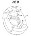
- FIG. 4Ais a perspective view from below of the cap of FIG. 4 ;
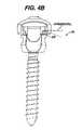
- FIG. 4Billustrates details of the anchor member of FIG. 4 ;
- FIG. 5shows a third embodiment of an anchor member and closure cap of the invention
- FIGS. 6A , 6 B and 6 Cillustrate the cap and head structure, respectively, of embodiment of FIG. 5 in greater detail
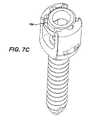
- FIGS. 7A , 7 B and 7 Cillustrate cap, head and assembled structure, respectively, of another internal twist cap embodiment
- FIGS. 8A and 8Billustrate a illustrates a further spinal anchor assembly of the invention in perspective with an internal twist cap in an open position ( 8 A) and in cross-section with the internal twist cap in a closed position ( 8 B);
- FIGS. 8C and 8Dillustrate the twist in cap of FIGS. 8A and 8B in perspective and top view
- FIG. 9illustrates in cross-section twist in cap and anchor head combinations of the invention in two different configurations.
- FIG. 10illustrates the two configurations illustrated in FIG. 9 with a loading applied to show the differing displacement characteristics of the two configurations.
- FIGS. 1A–1Cillustrate prior art anchor mechanisms for securing a fixation rod as used in spinal fixation.
- FIG. 1Aillustrates an anchor screw
- FIG. 1Bshows an offset tab having a slotted post for receiving the rod
- FIG. 1Cshows a combined system in which anchor screws secure rod-shaped offset elements that, in turn, each terminate in an end that grips a common fixation rod.
- a screw 1 with a rounded head 2carries a slotted top member 3 into which a rod 5 shown in phantom is clamped by screwing down a threaded press ring or set screw 6 .
- the press ring 6is turned by engagement along its central portion e.g., by an Allen wrench, and has external threads 6 a which fit corresponding internal threads 3 a of the top member 3 .
- a separate body 7fills the space between the inner wall of the top 3 and the ball head 2 of the screw 1 , so that when the rod is pressed down by the member 6 , the screw head is firmly gripped and all parts are rigidly held together.
- An external nut 8threads over the outside of the top to further strengthen and lock the assembly.
- the screw 1 , the press member 6 and the nut 8may all be installed with a straight tool, such as an Allen wrench or socket wrench, inserted directly along the axis of the screw.
- FIG. 1Bshows another anchor assembly 15 for receiving a fixation rod 5 .
- an offset tab constructionhaving a body 15 a that is anchored by a conventional bone screw 10 and including a slotted post (not numbered) for receiving the rod, is closed by a cap nut 17 which carries a pressure member 18 centrally thereon to press down against the rod 5 as the nut is tightened.
- the member 6 or 17 for clamping down against the rod 5installs by rotational movement.
- FIG. 1CAnother prior art anchor assembly is illustrated in FIG. 1C .
- a slotted body 21 or 22is carried either on a bone screw (not visible in the Figure) or on a short length of offset rod 22 a .
- the slotted body 21 or 22receives a rod and clamps it tightly.
- the slotted head member 21 or 22has angled or dovetailed walls at its upper portion, and a correspondingly shaped sliding cap member 23 is pressed along the dovetail into the upper region, sliding along the axis of the slot to close the slot and wedge firmly against the rod passing therethrough.
- this constructionhas a disadvantage that a lateral clearance along the length of the rod is necessary for movement of the closure member 23 into position.
- Other constructionsare shown in U.S. Pat. Nos. 5,346,493, 5,257,993 and elsewhere.
- the artincludes both one-piece, and many-piece anchor assemblies, and these may look like screws, or may be specialized elements that are themselves to be anchored by another assembly.
- the present inventionprovides a closing and fixing mechanism of enhanced utility, with a structure adaptable to much of this broad range of hooks, screws, connector assemblies and other orthopaedic anchor hardware involving one or more rod, cable, wire or other linking elements.
- FIG. 2illustrates a first embodiment of an anchor screw assembly 31 of the present invention.
- the anchor screw assembly 31includes a screw 32 and a top member 33 which may be integral with the screw or, like the prior art construction of FIG. 1A , may be a separate head member that secures to the proximal end of the screw 32 .
- the top member 33includes a slot indicated generally by 34 for receiving a rod, and contains at its uppermost region 35 , a plurality of segmented or partial flange members 36 a , 36 b , 36 c , 36 d which extend radially outward from its perimeter and have respective slots or spaces 37 a , 37 b therebetween.
- FIG. 1illustrates a first embodiment of an anchor screw assembly 31 of the present invention.
- the anchor screw assembly 31includes a screw 32 and a top member 33 which may be integral with the screw or, like the prior art construction of FIG. 1A , may be a separate head member that secures to the proximal end of the screw 32
- each of the flange segments 36 a , 36 b , 36 c , 36 dhas a lower surface 38 , as best seen in the end views of flange segments 36 a and 36 c , that engages a closure cap 40 ( FIGS. 3A–3C ). While not shown, one or more of the flange segments or cap may include a notch, detent or catch or a jamming feature, to prevent rotation in the opposite sense.
- the anchor screw or hook 31 of FIG. 2is used in conjunction with a closure cap 40 which is shown in an upward-facing view, from below, in FIG. 3C .
- the cap 40fits over and around the upper portion 35 of the slotted, rod receiving top member.
- the cap 40includes a body 41 having a central threaded bore 42 extending therethrough and a pair of dependent side members 43 a , 43 b on opposed peripheral sides thereof which extend downward on opposed sides surrounding the outer circumference of the top member 33 .
- Each of the side members 43 a , 43 bcarries mating inwardly directed protrusions 46 a , 46 b , and 46 c , 46 d , respectively, which are spaced apart and positioned to correspond to the segmented flange members 36 a – 36 d of the screw head.
- the protrusions 46 a to 46 dare positioned below the main body of the cap 41 by an amount corresponding to the maximum thickness of the flange segments 36 a to 36 d , and are rotationally offset so as to pass down through the gaps between segments and rotate into gripping engagement around the segments by a partial rotation of the cap 40 about the screw head assembly or top member 33 , in the manner of a bayonet mounted lid closure.
- the anchor screw 31 and the closure assembly 40 as well as the set screwall install by simple rotational movement of a tool that extends directly along the axis of the screw.
- the initial locking of the cap on the head assemblyis effected by a small rotational movement, substantially less than one-half turn, which corresponds approximately to the length of the lower surface 38 of one flange segment, or about 20 degrees of rotational movement.
- a very slight movementis sufficient to capture the rod 5 ( FIGS. 1A–1C ) within the slot 34 during initial setup or fitting of the fixation rod.
- twist-lock flanged anchoring assembly with a cap structure of the present inventionis readily adapted to diverse other fixation screws of known design, and thus in various alternative embodiments and adaptations may carry forward the advantages of those other designs.
- the locking cap assembly of FIGS. 2–3 of the inventionmay be adapted to an anchor assembly such as a reduction screw, anchor screw, or hook in which the anchor member possesses protruding reduction tabs that extend upwardly from the head of the anchoring assembly.
- the head 53 of the anchor assemblyhas a pair of reduction tabs 55 extending upwardly from the sides of the slot.
- the inventioncontemplates a closure cap 60 with a rim-engaging securing structure similar to that of cap 40 for engagement by a small rotational motion, but the cap structure further includes a pair of arcuate slots 62 a , 62 b located in its central region and sized for passage of the reduction tabs 55 or other protruding head structure therethrough.
- Each of the slots 62 a , 62 bextends past the edges of the tabs 55 , permitting sufficient rotation of the cap to lock the cap in position.
- the structure of the capitself strengthens or supports both the surrounding wall of the rod receiving slot, and the thin-walled tabs 55 which rise therefrom, while leaving the central on-axis region above the cap entirely unobstructed for insertion, for example, of a set screw along an axial direction, and permitting line-of-sight access by a driver for installation.
- the rod-receiving head assembly or top member 33 , 53may be integral with the anchor screw 35 , 52 or may be constituted by a separate slotted head member that fits about the top of the screw to grip the rod or other connecting linkage.
- the inventionapplies to diverse anchors, hooks, monoaxial screws, transverse connections or tandem connections, slotted connectors or the like.
- FIG. 4illustrates this aspect of the invention for a reduction tab embodiment of which the head is separate from the screw.
- the anchor screw assembly 50has a screw body 52 with an enlarged head 54 which may, for example, have an Allen or other female socket formed therein (not shown) for applying torque along the axis of the screw to insert the screw in bone.
- a slotted top member 53 having a tapered interior boreis first fitted over the head 54 , receiving the screw body from above, capturing the enlarged ball head 54 of the screw therein.
- a compressed member(not shown) which may be similar to element 7 of FIG.
- top member 53may be provided to create a binding fit, and this element may be fixed in place, for example, by swaging at opposed surface relief drillings 53 a , or it may fit by simple compression.
- top member 53as a separate head structure that is loosely fixed to, but originally decoupled from, the screw 52 in this manner allows the slot angle to be set at a later stage of installation, while avoiding the risk of losing separate small components.
- the cap 60 of this embodimentwhich is shown in a perspective view from below in FIG. 4A , is similar to that of the first described embodiment, but includes arcuate slots 62 a , 62 b to accommodate the projecting reduction tabs.
- the cap memberhaving a dependent locking rim that grips the outside of the slotted top and closes the slot by a partial rotation, provides a simple and unobstructed procedure for closing the head of the anchor and capturing the rod, cable or other linkage in the anchor assembly and clamping the linkage while fixing the orientation.
- the capextends radially beyond the outer radius of the anchor screw head assembly, and has a rim that extends to a greater diameter, and slides between the segmented flange bosses 36 to rotate into a captured position which closes the slot and captures the rod or other linkage within the head of the anchor assembly.
- a radial slant “RS” at an angle ⁇may be provided on one or more faces of the opposed locking members as shown in the detail FIG. 4B to assure that they cannot slip radially outward under pressure.
- the inventioncontemplates a twist-on cap member which fits within the head of the anchor assembly rather than extending over and locking on the outside of the head.
- FIG. 5illustrates one embodiment 100 of such a twist-in anchor closing mechanism.
- the anchor assembly 100has a screw portion 152 for anchoring in bone, and a head portion 153 for receiving the rod, cable or other linkage.
- a closure cap 140closes the slotted end of head 153 .
- the screw and headmay be separate assemblies, in which case the upper portion of the screw preferably has a ball end as described above that allows the head to pivot about the axis of the screw and achieve a further degree of freedom in angular orientation before clamping down.
- the cap or closure portion 140may have a central bore 145 which is internally threaded to accommodate a set screw to further clamp the rod in the slot; however, to simplify the drawing, threads are omitted from FIG. 5 .
- the internal closure cap 140has a plurality of radially protruding flange segments 146 , of which one is visible in the Figure, and the cap is pushed downwardly on the head so the respective inward and outward directed segments pass between each other, in a manner similar to the above-described embodiments.
- the segments 146fit between corresponding inwardly protruding segments 158 of the head 153 and lock thereagainst by a small rotation of the cap 140 .
- FIGS. 6A and 6Billustrate the structure of the twist-in cap 140 and the slotted head 153 in greater detail.
- FIG. 6Ashows the closure cap 140
- FIG. 6Bshows the head assembly 153 , of an internal closure locking cap of FIG. 5
- the head assembly 153 of the anchor screwhas a plurality of internally projecting bosses 158
- the closure cap 140has corresponding outwardly projecting bosses 146
- Respective bosses 146 , 158are dimensioned such that the cap 140 may be pushed downwardly between spaces of corresponding bosses to position the upper surface 149 of the cap bosses below the lower surface 159 of the retaining head bosses 158 .
- these mating contact surfacesare angled or sloped downwardly with a radial slant “RS” at an angle ⁇ (illustrated in FIGS. 5 and 6B ) toward the center.
- RSradial slant
- the cap 140when the cap 140 is rotated to place opposed bosses in an engagement with each other, the cap exerts a net inwardly directed force on the head to prevent spreading of the retaining slot.
- This effectcan be particularly advantageous when a set screw (not shown) is deployed in bore 145 as is further described below.
- the contours of the sloped endsare relatively sharply defined, effectively forming a circumferential ridge 149 a , 159 a and groove 149 b , 159 b on each of the respective components ( FIG. 6C ).
- the ridge of one partfits in the groove of the other, so that the closure is centered and grips over a substantial contact area.
- the twist-in caphas opposed edge flats 144 which may provide a contact or engagement surface for a tool such as a wrench used for turning the cap upon installation.
- Each of the flats 144has a corner to prevent over-rotation of the cap, so that upon insertion it rotates to exactly position the respective bosses 146 , 158 opposite each other as the anchor assembly is closed. The set screw is then tightened to secure the fixation linkage captured in the slot.
- FIGS. 7A–7Cillustrate another embodiment of a twist-in closure cap and spinal anchor assembly, having an anchor screw, a slotted head and a twist-in closure cap.
- the screw and headmay be separate assemblies, e.g., to achieve freedom in angular orientation before clamping down.
- the head and cap structuresimilarly may be adapted to spinal anchor assemblies of other types, such as transverse connectors, anchor plates and other link-receiving hardware.
- the capmay have a central bore which is internally threaded to accommodate a clamping set screw to lock and immobilize the linkage once it has been captured in the slot; however, to simplify the drawing, threads are omitted from FIGS. 7A and 7C .
- the radially protruding bosses or flange segments 146 of the cap, and the inwardly protruding bosses 158 of the headare arranged so the respective inward and outward directed segments pass between each other, when the cap is pushed downwardly into the head, in a manner similar to the above-described embodiments.
- the segments 146fit between corresponding, inwardly protruding segments 158 of the head and lock thereagainst by a small rotation of the cap.
- the twist-lock mechanismmay be configured to exert enhanced contact force in a detent region when the clamp screw is tightened down.
- thisis achieved in a presently preferred embodiment by providing lower and upper contact faces 159 , 149 on the segments 158 , 146 of the head and cap, respectively, that slope downward toward the center so that when the set screw is tightened the upward force on the cap draws the segments 158 inward and upward.
- a vertically-oriented protruding ridge 158 a and mating groove 146 aare formed on the head and cap, on or directly above the corresponding flange region of each, so that the ridge 158 a on the head is urged inwardly against the groove surface of the cap. This effectively locks the rotational detent to prevent any rotational movement of the cap once the set screw is tightened.
- the twist-in caphas a protruding stop face 164 that contacts the head and prevents over-rotation of the cap when it is turned to close the head.
- the caprotates (clockwise as shown) to position the bosses 146 , 158 exactly opposite each other as the anchor assembly is closed.
- the set screwis then tightened to secure the fixation linkage captured in the slot.
- Spinal anchor assembly 210for securing a spinal fixation element 212 illustrated in FIGS. 8A to 8D .
- Spinal anchor assembly 210includes an anchor element 214 adapted for attachment to bone.
- Anchor element 214has a distal portion 216 , a proximal portion 218 , and an open slot 220 that opens proximally to receive spinal fixation element 212 , which, in this embodiment, is a spinal fixation rod.
- First and second sidewalls 222 and 224are located on opposite sides of, and serve to define, open slot 220 .
- anchor element 214In its distal portion 218 , anchor element 214 includes a hollow cavity 226 configured to receive the head of a polyaxial screw. As described above, a person of ordinary skill in the art will recognize that other bone engaging configurations, such as monoaxial screws or offset bone engaging elements, could be used within the spirit of the invention. Anchor element 214 also defines a central longitudinal axis 228 that is generally perpendicular to spinal fixation element 212 and can include tool engagement elements 236 .
- a closure element 230is also provided in open slot 220 to capture and apply pressure to spinal fixation element 212 within the slot.
- anchor element 214includes a plurality of anchor flange segments 232 located on proximal portion 218 and extending inward toward longitudinal axis 228 .
- anchor flange segments 232there are two anchor flange segments 232 , one each extending inward from first and second sidewalls 222 , 224 .
- Anchor flange segments 232each include an inferior contact surface 234 extending in a direction toward the central longitudinal axis and toward distal portion 216 to define a radial slant (“RS” as illustrated in FIGS. 4B , 5 , 6 B, and 9 ).
- Closure element 230is further illustrated in FIGS. 8C and 8D , which can be viewed in conjunction with FIGS. 8A and 8B and which show closure element 230 in the context of spinal anchor assembly 210 .
- Closure element 230includes a closure body 238 and a plurality of closure flange segments 240 extending from closure body 238 in a direction that is transverse to anchor element central longitudinal axis 228 when closure element 230 is placed in the open slot 220 .
- Each closure flange segment 240includes a superior contact surface 242 extending in a direction away from central longitudinal axis 228 and toward the proximal portion 218 of anchor element 214 at the radial slant (RS) when the closure element is placed in open slot 220 so that closure flange segment superior surfaces 242 engage anchor element flange segment inferior surfaces 234 over a contact area when the closure element is placed in a closed position (as in FIG. 8B ) in the anchor element open slot 220 .
- RSradial slant
- Closure element 230can also include a threaded inner surface 244 into which a set screw 246 can be threaded.
- pressurecan be applied to spinal fixation element 212 by first placing closure element 230 in open slot 220 above the spinal fixation element in the open position ( FIG. 8A ), twisting the closure element so that flange 232 , 242 engage ( FIG. 8B ), and tightening set screw 246 down onto the spinal fixation element to hold it firmly in place.
- Closure element 230can further include one or more tool engagement elements 250 that can be used by an inserter tool to hold and/or twist the closure element into place.
- Closure element 230can still further include a locking or detent element 252 , in the illustrated embodiment a vertical slot, for engaging a corresponding detent element 254 on anchor element 214 .
- These locking elementsare similar to elements 146 a and 156 a which are more clearly disclosed in FIGS. 7A and 7B .
- anchor locking elements 254vertical protrusions that fit into vertical slots 252
- anchor locking elements 254are correspondingly located on anchor flange segments 232 above inferior surface 234 .
- anchor detent elements 254snap into closure detent elements 252 when the closure element reaches the fully closed position to lock the closure element in the closed position.
- FIGS. 9 and 10each illustrate two embodiments of a spinal anchor assembly.
- a spinal anchor assembly embodiment having a radial slant (RS) of 15 degreesis illustrated.
- closure element 230is unloaded (no pressure is applied to a spinal fixation element), while in FIG. 10 , the closure element is loaded (pressure is being applied to hold a spinal fixation element) and displacement of the features of the spinal anchor assembly is indicated.
- a spinal anchor assembly having a radial slant (RS) of 45 degreesis illustrated as well as certain other features of the invention.
- closure element 230is unloaded (no pressure is applied to a spinal fixation element), while in FIG. 10 , the closure element is loaded (pressure is being applied to hold a spinal fixation element) and displacement of the features is indicated.
- an outer surface 256 of closure flange 240is angled outward (away from central longitudinal axis 228 and toward the proximal portion of anchor element 214 ) at an angle 260 of approximately 10 degrees. Where outer surface 256 is also curved in a plane transverse to central longitudinal axis 228 (see FIGS. 8C and 8D ), outer surface 256 is in the shape of a partial cone as best illustrated in FIG. 8C .
- Side wall 224includes a correspondingly angled inner surface 258 , allowing cone shaped flange 240 to penetrate into anchor 214 upon closing of closure element 230 .
- angled nature of surfaces 256 and 258allow more mass to be included in closure flange 240 , making it stronger and more dimensionally stable, while the removal of mass or thinning of sidewall 222 allows for more resilience, and thus more displacement when such displacement is desired close to flange 232 inward while maintaining strength in lower parts of the sidewall.
- the increase in angle from 15 to 45 degrees from the left hand embodiment to the right hand embodimenthas a number of implications for an anchor assembly of the invention.
- One implicationis that, since the contact area where flange surfaces 234 , 242 meet is increased (and it is also increased as a result of cone angle 260 ), the stresses at the surfaces are reduced.
- a further implicationis that forces tending to draw sidewall inward will be increased due to the fact that the pressure in the contact area has been “aimed” inward, that is, cos(RS) is larger.
- FIG. 10where friction forces are overcome and flanges 232 , 240 can slide with respect to each other, anchor flange 232 and at least a portion of sidewall 222 is displaced inward, securing closure element 230 within anchor element 214 and causing locking elements 252 , 254 ( FIGS. 8A–8D ) to more securely lock, resulting in a more permanent and secure fixation of the spinal fixation element to the anchor.
- FIGS. 9 and 10can be varied within the scope and spirit of the invention.
- these embodimentsare formed (both closure 230 and anchor 214 elements) from Titanium (the coefficient of friction for Titanium on Titanium being approximately 0.15) and for typical loadings applied to spinal fixation elements, and the above testing shows that 15 degrees of radial slant does not allow the friction forces to be overcome while 45 degrees of radial slant does.
- a person of ordinary skill in the artcan determine specific angles of radial slant useful for particular configurations, materials, and loading forces using finite element analysis tools commonly used in the art.
Landscapes
- Health & Medical Sciences (AREA)
- Orthopedic Medicine & Surgery (AREA)
- Life Sciences & Earth Sciences (AREA)
- Neurology (AREA)
- Surgery (AREA)
- Heart & Thoracic Surgery (AREA)
- Engineering & Computer Science (AREA)
- Biomedical Technology (AREA)
- Nuclear Medicine, Radiotherapy & Molecular Imaging (AREA)
- Medical Informatics (AREA)
- Molecular Biology (AREA)
- Animal Behavior & Ethology (AREA)
- General Health & Medical Sciences (AREA)
- Public Health (AREA)
- Veterinary Medicine (AREA)
- Surgical Instruments (AREA)
- Orthopedics, Nursing, And Contraception (AREA)
- Prostheses (AREA)
Abstract
Description
This application is a continuation-in-part of U.S. patent application Ser. No. 09/667,937 to Bono et al., filed on Sep. 22, 2000, and entitled “Lock Cap Anchor Assembly for Orthopaedic Fixation,” now issued as U.S. Pat. No. 6,775,829, on Jun. 29, 2004, which application is incorporated herein by reference in its entirety.
The use of spinal fixation instrumentation to align and/or fix a desired relationship between adjacent vertebral bodies is well established. Such instrumentation typically includes a spinal fixation element, such as a relatively rigid fixation rod, that is coupled to adjacent vertebrae by attaching the element to pedicle screws which have been inserted into the patient's vertebrae or to spinal hooks which can be placed into a vertebral arch for coupling to the vertebral bodies. Once installed, the spinal fixation instrumentation holds the vertebrae in a desired spatial relationship, either until desired healing or spinal fusion has taken place, or for some longer period of time.
One example of a rod based spinal fixation system is provided in U.S. Pat. No. 5,005,562, issued Apr. 9, 1991 to Cotrel (which is hereby incorporated by reference). This system includes pedicle screws and spinal hook vertebral coupling elements (both screws and hooks) having integral U-shaped bodies that extend outward from the vertebrae to which they are attached. A spinal fixation rod is shaped as desired and fitted into the “U” of U-shaped bodies of adjacent vertebrae. The inner surfaces of the U-shaped body are threaded to accept a set screw, and rod is fixed to the vertebral coupling elements by threading a set screw into each of the U-shaped bodies to lock in the rod.
U.S. Pat. No. 5,545,165, issued Aug. 13, 1996 to Biedermann et al. (and incorporated herein by reference), illustrates an improvement in closure systems for fixing a rod to vertebral coupling elements over those provided by Cotrel. The Biedermann et al. system also uses pedicle screws and spinal hooks having U-shaped bodies that extend outward from the vertebrae to which they are attached. The U-shaped bodies of the Biedermann et al. system are threaded on both the inside and the outside. The rod is therefore locked in by both an inner set screw and an outer lock nut. In the illustrated embodiments, the inner set screw is adapted to be driven on its threads using a hex-shaped driver element, and the outer locking nut is provided with hex-shaped flat outer surfaces suitable for engagement with a wrench or similar driving tool.
U.S. Pat. No. 5,443,467, issued Aug. 22, 1995 to Biedermann et al. (and incorporated herein by reference) illustrates the use of an inner set screw and an outer lock nut to lock a rod into a U-shaped body in a polyaxial screw system. In this system, a pedicle screw having a spherical head is captured within a separate U-shaped receiver body. The angle of the screw with respect to the body can be changed until a head-locking element is tightened to lock the angle of the screw head within the receiver body. According to Biedermann et al., this combination of an inner set screw and an outer locking nut provides an advantage in that the force acting on the rod can be independently adjusted by either the inner set screw or the outer locking nut—a particularly useful advantage where the rod being fastened is curved and an exact fastening might only be possible by independent adjustment of the two closure elements. In addition, when tightened, the inner set screw and the outer locking nut tend to lock each other in their tightened positions.
Another style of closure system utilizes a cap element with a dovetail or dovetail channel that slides over the rod to close the top of the slot and wedge the rod firmly in position. This latter construction involves no rotation of threaded members, but has the disadvantage that a certain amount of unobstructed lateral space along the rod adjacent to the connection point is necessary for the sliding installation of the closure cap. Furthermore, the cap inserts or sliding wedge closures, while they eliminate the need for awkward screwing or rotational motion during installation, cannot be used with some existing reduction screws, translation hooks or other common hardware having lengthy protruding guide members, reduction tabs or the like. Moreover, the wedge/cap closures are a specialized component that may require the user to switch entirely over to a proprietary line of orthopaedic hardware if he is to utilize the full range of hook, tab, plate and screw fixation points that may be required in spinal surgery.
While the closure systems described above have in at least some instances been quite successful, it would be beneficial to provide a closure assembly that could securely lock down a rod down while requiring only a small number of locking steps by the surgeon and small lateral clearances surrounding the closure.
The present invention improves on the art by providing a spinal anchor assembly for securing a fixation element having an anchor element and a twist-in cap. The anchor element is configured for attachment to a bone, typically by comprising a mono- or polyaxial screw or hook, and includes a proximal portion having an open slot for receiving the fixation element and having radially inwardly protruding flange segments. The twist-in cap is received in and closes the open slot. The proximal portion of the anchor and the cap are adapted to twist-lock together by a partial rotation of the cap from an open position to a closed position to cover the slot so as to capture the fixation element and to lock the cap in the closed position.
In specific embodiments, the cap and anchor elements each include detent elements that engage to lock the cap in the closed position. A first one of the cap and anchor detent elements can be a protrusion, while a second one of the cap and anchor detent elements can be a recess configured to capture the protrusion and the anchor detent element can be provided on an anchor flange segment. Still further, the first one of the cap and anchor detent elements can be a longitudinal protrusion and the second one of the cap and anchor detent elements can be a longitudinal slot.
In further specific embodiments, the cap includes radially outwardly protruding flange segments with the cap flange segments being captured by the anchor element flange segments when the cap is in the closed position. The cap and anchor flange segments can be provided with a radial slant in a direction that extends toward a distal end of the anchor element when moving inward toward the cap and this radial slant can be configured such that securing the fixation element within the slot causes the flange segments to slide with respect to each other, causes a displacement of the anchor flange segments inwardly, and/or causes any detent elements to engage with greater strength. Pressure can be provided to further secure the fixation element in the open slot by providing the cap with a centrally placed clamping member that may be tightened down on the fixation element. In specific embodiments, the clamping member may be a set screw threaded into a central bore in the cap.
In an additional aspect of the invention, an anchor assembly for securing a fixation element is provided having an anchor element and a closure element. The anchor element is adapted for attachment to bone and defines a central longitudinal axis. The anchor element has an open slot for receiving the fixation element, side walls on opposed sides of the open slot, a proximal portion, a distal portion, and an anchor flange segment extending from each of the side walls in a direction toward the central longitudinal axis. The anchor flange segments each include an inferior contact surface. The closure element closes the open slot in the anchor element and applies pressure to the fixation element to capture the fixation element within the open slot. The closure element includes a closure body and a plurality of closure flange segments extending from the closure body in a direction that is transverse to the anchor element central longitudinal axis when the closure element is placed in the open slot. Each closure flange segment includes a superior contact surface extending in a direction away from the central longitudinal axis when the closure element is placed in the open slot so that the closure flange segment superior surfaces engage the anchor element flange segment inferior surfaces over a contact area when the closure element is placed in a closed position in the anchor element open slot. The closure flange segments further include exterior surfaces that extend away from the longitudinal axis and proximally when the closure element is placed in the open slot to provide a partial cone shaped outer surface to the closure flanges.
In a still further aspect of the invention, an anchor assembly for securing a fixation element is provided having an anchor element and a closure element. The anchor element is adapted for attachment to bone and defines a central longitudinal axis. The anchor element has an open slot for receiving the fixation element, side walls on opposed sides of the open slot, a proximal portion, a distal portion, and an anchor flange segment extending from each of the side walls in a direction toward the central longitudinal axis. The anchor flange segments each include an inferior contact surface extending in a direction toward the central longitudinal axis and toward the distal portion to define a radial slant. The closure element closes the open slot in the anchor element and applies pressure to the fixation element to capture the fixation element within the open slot. The closure element includes a closure body and a plurality of closure flange segments extending from the closure body in a direction that is transverse to the anchor element central longitudinal axis when the closure element is placed in the open slot. Each closure flange segment includes a superior contact surface extending in a direction away from the central longitudinal axis and toward the proximal portion of the anchor element at the radial slant when the closure element is placed in the open slot so that the closure flange segment superior surfaces engage the anchor element flange segment inferior surfaces over a contact area when the closure element is placed in a closed position in the anchor element open slot. The radial slant is further configured to permit the sliding of the anchor flange segment inferior surfaces with respect to the closure flange segment superior surfaces upon pressure being applied on the fixation element.
The invention will be more fully understood from the following detailed description taken in conjunction with the accompanying drawings:
FIGS.3 and3A–3C show views of a closure cap utilized with the anchor screw ofFIG. 2 in accordance with the present invention;
The invention and its range of embodiments will be better understood following a brief description of prior art, illustrating approaches to one- and two-part anchor assemblies, as well as certain common constructions.
Another prior art anchor assembly is illustrated inFIG. 1C . In this article, a slottedbody rod 22a. In both cases, the slottedbody head member cap member 23 is pressed along the dovetail into the upper region, sliding along the axis of the slot to close the slot and wedge firmly against the rod passing therethrough. As noted above, this construction has a disadvantage that a lateral clearance along the length of the rod is necessary for movement of theclosure member 23 into position. Other constructions are shown in U.S. Pat. Nos. 5,346,493, 5,257,993 and elsewhere.
Thus, the art includes both one-piece, and many-piece anchor assemblies, and these may look like screws, or may be specialized elements that are themselves to be anchored by another assembly. As described further below, the present invention provides a closing and fixing mechanism of enhanced utility, with a structure adaptable to much of this broad range of hooks, screws, connector assemblies and other orthopaedic anchor hardware involving one or more rod, cable, wire or other linking elements.
The anchor screw or hook31 ofFIG. 2 is used in conjunction with a closure cap40 which is shown in an upward-facing view, from below, inFIG. 3C . The cap40 fits over and around theupper portion 35 of the slotted, rod receiving top member. As shownFIG. 3 , the cap40 includes abody 41 having a central threaded bore42 extending therethrough and a pair ofdependent side members top member 33. Each of theside members protrusions segmented flange members 36a–36dof the screw head. In particular, theprotrusions 46ato46dare positioned below the main body of thecap 41 by an amount corresponding to the maximum thickness of theflange segments 36ato36d, and are rotationally offset so as to pass down through the gaps between segments and rotate into gripping engagement around the segments by a partial rotation of the cap40 about the screw head assembly ortop member 33, in the manner of a bayonet mounted lid closure. This secures the cap40 on the top member closing the slot to prevent movement of the rod or cable from the head along the axial direction of thescrew 32. A set screw (not shown) threaded through theaperture 42 is then tightened to clamp firmly down against the rod, cable or other linkage captured in the slot34 (FIG. 2 ).
Advantageously, with the foregoing construction, theanchor screw 31 and the closure assembly40 as well as the set screw (not illustrated) all install by simple rotational movement of a tool that extends directly along the axis of the screw. Moreover, as illustrated, the initial locking of the cap on the head assembly is effected by a small rotational movement, substantially less than one-half turn, which corresponds approximately to the length of thelower surface 38 of one flange segment, or about 20 degrees of rotational movement. Thus a very slight movement is sufficient to capture the rod5 (FIGS. 1A–1C ) within theslot 34 during initial setup or fitting of the fixation rod.
This twist-lock flanged anchoring assembly with a cap structure of the present invention is readily adapted to diverse other fixation screws of known design, and thus in various alternative embodiments and adaptations may carry forward the advantages of those other designs. Thus, for example, the locking cap assembly ofFIGS. 2–3 of the invention may be adapted to an anchor assembly such as a reduction screw, anchor screw, or hook in which the anchor member possesses protruding reduction tabs that extend upwardly from the head of the anchoring assembly.
Such anembodiment 50 is shown inFIG. 4 . In this embodiment, thehead 53 of the anchor assembly has a pair ofreduction tabs 55 extending upwardly from the sides of the slot. In this case, the invention contemplates aclosure cap 60 with a rim-engaging securing structure similar to that of cap40 for engagement by a small rotational motion, but the cap structure further includes a pair ofarcuate slots reduction tabs 55 or other protruding head structure therethrough. Each of theslots tabs 55, permitting sufficient rotation of the cap to lock the cap in position. The structure of the cap itself strengthens or supports both the surrounding wall of the rod receiving slot, and the thin-walled tabs 55 which rise therefrom, while leaving the central on-axis region above the cap entirely unobstructed for insertion, for example, of a set screw along an axial direction, and permitting line-of-sight access by a driver for installation.
In any of the foregoing constructions, the rod-receiving head assembly ortop member anchor screw
Thecap 60 of this embodiment, which is shown in a perspective view from below inFIG. 4A , is similar to that of the first described embodiment, but includesarcuate slots
In each of the foregoing illustrated embodiments, the cap extends radially beyond the outer radius of the anchor screw head assembly, and has a rim that extends to a greater diameter, and slides between the segmented flange bosses36 to rotate into a captured position which closes the slot and captures the rod or other linkage within the head of the anchor assembly. A radial slant “RS” at an angle Θ may be provided on one or more faces of the opposed locking members as shown in the detailFIG. 4B to assure that they cannot slip radially outward under pressure.
In further embodiments, the invention contemplates a twist-on cap member which fits within the head of the anchor assembly rather than extending over and locking on the outside of the head.
Theinternal closure cap 140 has a plurality of radially protrudingflange segments 146, of which one is visible in the Figure, and the cap is pushed downwardly on the head so the respective inward and outward directed segments pass between each other, in a manner similar to the above-described embodiments. Thus, thesegments 146 fit between corresponding inwardly protrudingsegments 158 of thehead 153 and lock thereagainst by a small rotation of thecap 140.
As best seen inFIGS. 5 and 6A , the twist-in cap has opposededge flats 144 which may provide a contact or engagement surface for a tool such as a wrench used for turning the cap upon installation. Each of theflats 144 has a corner to prevent over-rotation of the cap, so that upon insertion it rotates to exactly position therespective bosses
In this embodiment, the radially protruding bosses orflange segments 146 of the cap, and the inwardly protrudingbosses 158 of the head are arranged so the respective inward and outward directed segments pass between each other, when the cap is pushed downwardly into the head, in a manner similar to the above-described embodiments. Thus, thesegments 146 fit between corresponding, inwardly protrudingsegments 158 of the head and lock thereagainst by a small rotation of the cap. In addition, the twist-lock mechanism may be configured to exert enhanced contact force in a detent region when the clamp screw is tightened down.
As shown inFIGS. 7A–C , this is achieved in a presently preferred embodiment by providing lower and upper contact faces159,149 on thesegments segments 158 inward and upward. A vertically-oriented protrudingridge 158aandmating groove 146aare formed on the head and cap, on or directly above the corresponding flange region of each, so that theridge 158aon the head is urged inwardly against the groove surface of the cap. This effectively locks the rotational detent to prevent any rotational movement of the cap once the set screw is tightened.
As further seen inFIGS. 7A and 7C , the twist-in cap has a protrudingstop face 164 that contacts the head and prevents over-rotation of the cap when it is turned to close the head. Thus, upon insertion the cap rotates (clockwise as shown) to position thebosses
Further features and advantages of the invention will now be described with respect to aspinal anchor assembly 210 for securing aspinal fixation element 212 illustrated inFIGS. 8A to 8D .Spinal anchor assembly 210, best illustrated in perspective inFIG. 8A and in cross-section inFIG. 8B , includes ananchor element 214 adapted for attachment to bone.Anchor element 214 has adistal portion 216, aproximal portion 218, and anopen slot 220 that opens proximally to receivespinal fixation element 212, which, in this embodiment, is a spinal fixation rod. First andsecond sidewalls open slot 220. In itsdistal portion 218,anchor element 214 includes ahollow cavity 226 configured to receive the head of a polyaxial screw. As described above, a person of ordinary skill in the art will recognize that other bone engaging configurations, such as monoaxial screws or offset bone engaging elements, could be used within the spirit of the invention.Anchor element 214 also defines a centrallongitudinal axis 228 that is generally perpendicular tospinal fixation element 212 and can includetool engagement elements 236.
Aclosure element 230 is also provided inopen slot 220 to capture and apply pressure tospinal fixation element 212 within the slot. To engageclosure element 230,anchor element 214 includes a plurality ofanchor flange segments 232 located onproximal portion 218 and extending inward towardlongitudinal axis 228. In the illustrated embodiment, there are twoanchor flange segments 232, one each extending inward from first andsecond sidewalls Anchor flange segments 232 each include aninferior contact surface 234 extending in a direction toward the central longitudinal axis and towarddistal portion 216 to define a radial slant (“RS” as illustrated inFIGS. 4B ,5,6B, and9).
In the right hand embodiment (and as best seen inFIG. 9 ), anouter surface 256 ofclosure flange 240 is angled outward (away from centrallongitudinal axis 228 and toward the proximal portion of anchor element214) at anangle 260 of approximately 10 degrees. Whereouter surface 256 is also curved in a plane transverse to central longitudinal axis228 (seeFIGS. 8C and 8D ),outer surface 256 is in the shape of a partial cone as best illustrated inFIG. 8C .Side wall 224 includes a correspondingly angledinner surface 258, allowing cone shapedflange 240 to penetrate intoanchor 214 upon closing ofclosure element 230. In addition, the angled nature ofsurfaces closure flange 240, making it stronger and more dimensionally stable, while the removal of mass or thinning ofsidewall 222 allows for more resilience, and thus more displacement when such displacement is desired close toflange 232 inward while maintaining strength in lower parts of the sidewall.
The increase in angle from 15 to 45 degrees from the left hand embodiment to the right hand embodiment has a number of implications for an anchor assembly of the invention. One implication is that, since the contact area where flange surfaces234,242 meet is increased (and it is also increased as a result of cone angle260), the stresses at the surfaces are reduced. A further implication is that forces tending to draw sidewall inward will be increased due to the fact that the pressure in the contact area has been “aimed” inward, that is, cos(RS) is larger. In addition, the configuration on the right hand embodiment with RS=45 degrees is such that, when the flanges are loaded (by applying pressure to the spinal fixation element through closure element230) andsidewall 222 is drawn inward, friction betweensurfaces sidewall 222 andanchor flange 232 being displaced inward as illustrated inFIG. 10 . As shown inFIG. 10 , where friction forces are overcome andflanges anchor flange 232 and at least a portion ofsidewall 222 is displaced inward, securingclosure element 230 withinanchor element 214 and causinglocking elements 252,254 (FIGS. 8A–8D ) to more securely lock, resulting in a more permanent and secure fixation of the spinal fixation element to the anchor.
Alternatively, as illustrated in the left hand embodiment inFIG. 10 , where angle RS is not steep enough, friction forces between the flanges are not overcome and, as a result of the bending moment placed onsidewall 222 by the upward component of the pressure fromclosure flange 240 onanchor flange 232,anchor flange 232 and a portion ofsidewall 222 may actually be displaced outward, which can have a deleterious effect on the locking provided byelements
It should be understood a person skilled in the art that the specific angles used in the embodiments ofFIGS. 9 and 10 can be varied within the scope and spirit of the invention. For example, these embodiments are formed (bothclosure 230 andanchor 214 elements) from Titanium (the coefficient of friction for Titanium on Titanium being approximately 0.15) and for typical loadings applied to spinal fixation elements, and the above testing shows that 15 degrees of radial slant does not allow the friction forces to be overcome while 45 degrees of radial slant does. A person of ordinary skill in the art can determine specific angles of radial slant useful for particular configurations, materials, and loading forces using finite element analysis tools commonly used in the art.
The invention being thus disclosed and illustrative embodiments depicted herein, further variations and modifications of the invention will occur to those skilled in the art. All such variations and modifications are considered to be within the scope of the invention, as defined by the claims appended hereto and equivalents thereof.
Claims (25)
1. An anchor assembly for securing a fixation element, comprising:
an anchor element adapted for attachment to bone and defining a central longitudinal axis, the anchor element having an open slot for receiving the fixation element, side walls on opposed sides of the open slot, a proximal portion, a distal portion, and an anchor flange segment extending from each of the side walls in a direction toward the central longitudinal axis, the anchor flange segments each including an inferior contact surface; and
a closure element for closing the open slot in the anchor element and applying pressure to the fixation element to capture the fixation element within the open slot, the closure element including a closure body and a plurality of closure flange segments extending from the closure body in a direction that is transverse to the anchor element central longitudinal axis when the closure element is placed in the open slot, each closure flange segment including a superior contact surface extending in a direction away from the central longitudinal axis when the closure element is placed in the open slot so that the closure flange segment superior surfaces engage the anchor element flange segment inferior surfaces over a contact area when the closure element is placed in a closed position in the anchor element open slot;
wherein the closure flange segments further include exterior surfaces that extend outward away from the longitudinal axis and toward the proximal portion of the anchor element at an angle when the closure element is placed in the open slot to provide a partial cone shaped outer surface to the closure flanges.
2. The assembly ofclaim 1 , wherein the side walls become thinner in a proximal direction to correspond to the partial cone shaped outer surfaces of the closure flanges.
3. The assembly ofclaim 1 , wherein the anchor flange segment inferior surfaces extend in a direction toward the central longitudinal axis and toward the distal portion to define a radial slant and the closure flange segment superior surfaces extend in a direction away from the central longitudinal axis and toward the proximal portion of the anchor element at the radial slant when the closure element is placed in the open slot.
4. The assembly ofclaim 3 , wherein the radial slant is configured to permit the sliding of the anchor flange segment inferior surfaces with respect to the closure flange segment superior surfaces upon pressure being applied on the fixation element.
5. The assembly ofclaim 3 , wherein the radial slant is configured so that, when the closure element is in its closed position and pressure is applied to secure the fixation element within the open slot in the anchor element, the sidewalls are drawn together.
6. The assembly ofclaim 3 , wherein the radial slant is at an angle of approximately 45 degrees to the central longitudinal axis.
7. The assembly ofclaim 1 , wherein the closure element and anchor element each include detent elements that engage to lock the closure element in the closed position.
8. The assembly ofclaim 7 , wherein a first one of the closure and anchor detent elements is a protrusion and a second one of the closure and anchor detent elements is a recess configured to capture the protuberance.
9. The assembly ofclaim 8 , wherein the anchor detent element is provided on the anchor flange segment.
10. The assembly ofclaim 9 , wherein the first one of the closure and anchor detent elements is a longitudinal protrusion and the second one of the closure and anchor detent elements is a longitudinal slot.
11. The assembly ofclaim 9 , wherein the flanges are configured such that applying pressure to the fixation element within the slot causes the detent elements to engage with greater strength.
12. The assembly ofclaim 1 , wherein the closure element further includes a centrally placed clamping member for applying pressure to the fixation element within the slot.
13. The assembly ofclaim 12 , wherein the clamping member is a set screw.
14. An anchor assembly for securing a fixation element, comprising:
an anchor element adapted for attachment to bone and defining a central longitudinal axis, the anchor element having an open slot for receiving the fixation element, side walls on opposed sides of the open slot, a proximal portion, a distal portion, and an anchor flange segment extending from each of the side walls in a direction toward the central longitudinal axis, the anchor flange segments each including an inferior contact surface extending in a direction toward the central longitudinal axis and toward the distal portion to define a radial slant; and
a closure element for closing the open slot in the anchor element and applying pressure to the fixation element to capture the fixation element within the open slot, the closure element including a closure body and a plurality of closure flange segments extending from the closure body in a direction that is transverse to the anchor element central longitudinal axis when the closure element is placed in the open slot, each closure flange segment including a superior contact surface extending in a direction away from the central longitudinal axis and toward the proximal portion of the anchor element at the radial slant when the closure element is placed in the open slot so that the closure flange segment superior surfaces engage the anchor element flange segment inferior surfaces over a contact area when the closure element is placed in a closed position in the anchor element open slot;
wherein the radial slant causes sliding of the anchor flange segment inferior surfaces with respect to the closure flange segment superior surfaces upon pressure being applied on the fixation element so that a sidewall of the anchor element and anchor flange segment are displaced inward toward the central longitudinal axis.
15. The assembly ofclaim 14 , wherein the closure flange segments further include exterior surfaces that extend away from the longitudinal axis and proximally when the closure element is placed in the open slot to provide a partial cone shaped outer surface to the closure flanges.
16. The assembly ofclaim 15 , wherein the side walls become thinner in a proximal direction to correspond to the partial cone shaped outer surfaces of the closure flanges.
17. The assembly ofclaim 14 , wherein the radial slant is configured so that, when the closure element is in its closed position and pressure is applied to secure the fixation element within the open slot in the anchor element, the sidewalls are drawn together.
18. The assembly ofclaim 14 , wherein the radial slant is at an angle of approximately 45 degrees to the central longitudinal axis.
19. The assembly ofclaim 14 , wherein the closure element and anchor element each include detent elements that engage to lock the closure element in the closed position.
20. The assembly ofclaim 19 , wherein a first one of the closure and anchor detent elements is a protrusion and a second one of the closure and anchor detent elements is a recess configured to capture the protuberance.
21. The assembly ofclaim 20 , wherein the anchor detent element is provided on the anchor flange segment.
22. The assembly ofclaim 21 , wherein the first one of the closure and anchor detent elements is a longitudinal protrusion and the second one of the closure and anchor detent elements is a longitudinal slot.
23. The assembly ofclaim 19 , wherein the radial slant is in a direction such that applying pressure to the fixation element within the slot causes the detent elements to engage with greater strength.
24. The assembly ofclaim 14 , wherein the closure element further includes a centrally placed clamping member for applying pressure to the fixation element within the slot.
25. The assembly ofclaim 24 , wherein the clamping member is a set screw.
Priority Applications (1)
| Application Number | Priority Date | Filing Date | Title |
|---|---|---|---|
| US10/606,200US7125426B2 (en) | 2000-09-22 | 2003-06-25 | Locking cap assembly for spinal fixation instrumentation |
Applications Claiming Priority (2)
| Application Number | Priority Date | Filing Date | Title |
|---|---|---|---|
| US09/667,937US6755829B1 (en) | 2000-09-22 | 2000-09-22 | Lock cap anchor assembly for orthopaedic fixation |
| US10/606,200US7125426B2 (en) | 2000-09-22 | 2003-06-25 | Locking cap assembly for spinal fixation instrumentation |
Related Parent Applications (1)
| Application Number | Title | Priority Date | Filing Date |
|---|---|---|---|
| US09/667,937Continuation-In-PartUS6755829B1 (en) | 2000-09-22 | 2000-09-22 | Lock cap anchor assembly for orthopaedic fixation |
Publications (2)
| Publication Number | Publication Date |
|---|---|
| US20050177154A1 US20050177154A1 (en) | 2005-08-11 |
| US7125426B2true US7125426B2 (en) | 2006-10-24 |
Family
ID=24680287
Family Applications (5)
| Application Number | Title | Priority Date | Filing Date |
|---|---|---|---|
| US09/667,937Expired - LifetimeUS6755829B1 (en) | 2000-09-22 | 2000-09-22 | Lock cap anchor assembly for orthopaedic fixation |
| US10/606,200Expired - LifetimeUS7125426B2 (en) | 2000-09-22 | 2003-06-25 | Locking cap assembly for spinal fixation instrumentation |
| US10/828,508Expired - LifetimeUS7081117B2 (en) | 2000-09-22 | 2004-04-20 | Locking cap assembly for spinal fixation instrumentation |
| US11/421,921Expired - Fee RelatedUS8444676B2 (en) | 2000-09-22 | 2006-06-02 | Locking cap assembly for spinal fixation instrumentation |
| US13/871,244Expired - Fee RelatedUS9795415B2 (en) | 2000-09-22 | 2013-04-26 | Locking cap assembly for spinal fixation instrumentation |
Family Applications Before (1)
| Application Number | Title | Priority Date | Filing Date |
|---|---|---|---|
| US09/667,937Expired - LifetimeUS6755829B1 (en) | 2000-09-22 | 2000-09-22 | Lock cap anchor assembly for orthopaedic fixation |
Family Applications After (3)
| Application Number | Title | Priority Date | Filing Date |
|---|---|---|---|
| US10/828,508Expired - LifetimeUS7081117B2 (en) | 2000-09-22 | 2004-04-20 | Locking cap assembly for spinal fixation instrumentation |
| US11/421,921Expired - Fee RelatedUS8444676B2 (en) | 2000-09-22 | 2006-06-02 | Locking cap assembly for spinal fixation instrumentation |
| US13/871,244Expired - Fee RelatedUS9795415B2 (en) | 2000-09-22 | 2013-04-26 | Locking cap assembly for spinal fixation instrumentation |
Country Status (9)
| Country | Link |
|---|---|
| US (5) | US6755829B1 (en) |
| EP (2) | EP1190678B1 (en) |
| JP (1) | JP5312719B2 (en) |
| KR (1) | KR20020023652A (en) |
| AT (2) | ATE397898T1 (en) |
| AU (1) | AU756121B2 (en) |
| CA (2) | CA2357606C (en) |
| DE (2) | DE60143138D1 (en) |
| ES (1) | ES2305036T3 (en) |
Cited By (141)
| Publication number | Priority date | Publication date | Assignee | Title |
|---|---|---|---|---|
| US20060129149A1 (en)* | 2004-04-08 | 2006-06-15 | Andrew Iott | Polyaxial screw |
| US20060235393A1 (en)* | 2000-09-22 | 2006-10-19 | Depuy Spine, Inc. | Locking cap assembly for spinal fixation instrumentation |
| US20070055235A1 (en)* | 2003-02-05 | 2007-03-08 | Pioneer Laboratories, Inc. | Low profile spinal fixation system |
| US20070093827A1 (en)* | 2005-10-04 | 2007-04-26 | Warnick David R | Pedicle screw system with provisional locking aspects |
| US20070123862A1 (en)* | 2004-10-25 | 2007-05-31 | Warnick David R | Bone fixation system and method for using the same |
| US20070123867A1 (en)* | 2005-07-29 | 2007-05-31 | X-Spine Systems, Inc. | Capless multiaxial screw and spinal fixation assembly and method |
| US20080015584A1 (en)* | 2002-04-18 | 2008-01-17 | Aesculap Implant Systems | Screw and rod fixation assembly and device |
| US20080039839A1 (en)* | 2005-02-23 | 2008-02-14 | Pioneer Laboratories, Inc. | Minimally invasive surgical system |
| US20080045955A1 (en)* | 2006-08-16 | 2008-02-21 | Berrevoets Gregory A | Spinal Rod Anchor Device and Method |
| US20080312655A1 (en)* | 2007-06-14 | 2008-12-18 | X-Spine Systems, Inc. | Polyaxial screw system and method having a hinged receiver |
| US20090082819A1 (en)* | 2007-06-28 | 2009-03-26 | Spinal Elements, Inc. | Spinal stabilization device |
| US20090088800A1 (en)* | 2007-08-24 | 2009-04-02 | Spinal Elements, Inc. | Loop rod spinal stablization device |
| US20090163961A1 (en)* | 2007-12-19 | 2009-06-25 | X-Spine Systems, Inc. | Offset multiaxial or polyaxial screw, system and assembly |
| US20090187217A1 (en)* | 2008-01-18 | 2009-07-23 | Mark Weiman | Transverse Connector |
| US7635380B2 (en) | 2007-06-05 | 2009-12-22 | Spartek Medical, Inc. | Bone anchor with a compressor element for receiving a rod for a dynamic stabilization and motion preservation spinal implantation system and method |
| US7662172B2 (en) | 2004-10-25 | 2010-02-16 | X-Spine Systems, Inc. | Pedicle screw systems and methods of assembling/installing the same |
| US20100063552A1 (en)* | 2005-05-04 | 2010-03-11 | Spinefrontier, Inc | Spinal screw assembly and screw insertion tool |
| US7854751B2 (en) | 2003-12-16 | 2010-12-21 | Dupuy Spine, Inc. | Percutaneous access devices and bone anchor assemblies |
| US7875065B2 (en) | 2004-11-23 | 2011-01-25 | Jackson Roger P | Polyaxial bone screw with multi-part shank retainer and pressure insert |
| US7901435B2 (en) | 2004-05-28 | 2011-03-08 | Depuy Spine, Inc. | Anchoring systems and methods for correcting spinal deformities |
| US7918857B2 (en) | 2006-09-26 | 2011-04-05 | Depuy Spine, Inc. | Minimally invasive bone anchor extensions |
| US7963978B2 (en) | 2007-06-05 | 2011-06-21 | Spartek Medical, Inc. | Method for implanting a deflection rod system and customizing the deflection rod system for a particular patient need for dynamic stabilization and motion preservation spinal implantation system |
| US7967850B2 (en) | 2003-06-18 | 2011-06-28 | Jackson Roger P | Polyaxial bone anchor with helical capture connection, insert and dual locking assembly |
| US7993372B2 (en) | 2007-06-05 | 2011-08-09 | Spartek Medical, Inc. | Dynamic stabilization and motion preservation spinal implantation system with a shielded deflection rod system and method |
| US8007518B2 (en) | 2008-02-26 | 2011-08-30 | Spartek Medical, Inc. | Load-sharing component having a deflectable post and method for dynamic stabilization of the spine |
| US8012181B2 (en) | 2008-02-26 | 2011-09-06 | Spartek Medical, Inc. | Modular in-line deflection rod and bone anchor system and method for dynamic stabilization of the spine |
| US8016861B2 (en) | 2008-02-26 | 2011-09-13 | Spartek Medical, Inc. | Versatile polyaxial connector assembly and method for dynamic stabilization of the spine |
| US8021396B2 (en) | 2007-06-05 | 2011-09-20 | Spartek Medical, Inc. | Configurable dynamic spinal rod and method for dynamic stabilization of the spine |
| US8043337B2 (en) | 2006-06-14 | 2011-10-25 | Spartek Medical, Inc. | Implant system and method to treat degenerative disorders of the spine |
| US8048115B2 (en) | 2007-06-05 | 2011-11-01 | Spartek Medical, Inc. | Surgical tool and method for implantation of a dynamic bone anchor |
| US8057517B2 (en) | 2008-02-26 | 2011-11-15 | Spartek Medical, Inc. | Load-sharing component having a deflectable post and centering spring and method for dynamic stabilization of the spine |
| US8066739B2 (en) | 2004-02-27 | 2011-11-29 | Jackson Roger P | Tool system for dynamic spinal implants |
| US8083772B2 (en) | 2007-06-05 | 2011-12-27 | Spartek Medical, Inc. | Dynamic spinal rod assembly and method for dynamic stabilization of the spine |
| US8083775B2 (en) | 2008-02-26 | 2011-12-27 | Spartek Medical, Inc. | Load-sharing bone anchor having a natural center of rotation and method for dynamic stabilization of the spine |
| US8092501B2 (en) | 2007-06-05 | 2012-01-10 | Spartek Medical, Inc. | Dynamic spinal rod and method for dynamic stabilization of the spine |
| US8097025B2 (en) | 2005-10-25 | 2012-01-17 | X-Spine Systems, Inc. | Pedicle screw system configured to receive a straight or curved rod |
| US8097024B2 (en) | 2008-02-26 | 2012-01-17 | Spartek Medical, Inc. | Load-sharing bone anchor having a deflectable post and method for stabilization of the spine |
| US8096996B2 (en) | 2007-03-20 | 2012-01-17 | Exactech, Inc. | Rod reducer |
| US8100946B2 (en) | 2005-11-21 | 2012-01-24 | Synthes Usa, Llc | Polyaxial bone anchors with increased angulation |
| US8100915B2 (en) | 2004-02-27 | 2012-01-24 | Jackson Roger P | Orthopedic implant rod reduction tool set and method |
| US8105368B2 (en) | 2005-09-30 | 2012-01-31 | Jackson Roger P | Dynamic stabilization connecting member with slitted core and outer sleeve |
| US8114134B2 (en) | 2007-06-05 | 2012-02-14 | Spartek Medical, Inc. | Spinal prosthesis having a three bar linkage for motion preservation and dynamic stabilization of the spine |
| US8137386B2 (en) | 2003-08-28 | 2012-03-20 | Jackson Roger P | Polyaxial bone screw apparatus |
| US8152810B2 (en) | 2004-11-23 | 2012-04-10 | Jackson Roger P | Spinal fixation tool set and method |
| US8211155B2 (en) | 2008-02-26 | 2012-07-03 | Spartek Medical, Inc. | Load-sharing bone anchor having a durable compliant member and method for dynamic stabilization of the spine |
| US8226690B2 (en) | 2005-07-22 | 2012-07-24 | The Board Of Trustees Of The Leland Stanford Junior University | Systems and methods for stabilization of bone structures |
| US8236035B1 (en) | 2009-06-16 | 2012-08-07 | Bedor Bernard M | Spinal fixation system and method |
| US8257397B2 (en) | 2009-12-02 | 2012-09-04 | Spartek Medical, Inc. | Low profile spinal prosthesis incorporating a bone anchor having a deflectable post and a compound spinal rod |
| US8257398B2 (en) | 2003-06-18 | 2012-09-04 | Jackson Roger P | Polyaxial bone screw with cam capture |
| US8257396B2 (en) | 2003-06-18 | 2012-09-04 | Jackson Roger P | Polyaxial bone screw with shank-retainer inset capture |
| US8267979B2 (en) | 2008-02-26 | 2012-09-18 | Spartek Medical, Inc. | Load-sharing bone anchor having a deflectable post and axial spring and method for dynamic stabilization of the spine |
| US8267969B2 (en) | 2004-10-20 | 2012-09-18 | Exactech, Inc. | Screw systems and methods for use in stabilization of bone structures |
| US8308782B2 (en) | 2004-11-23 | 2012-11-13 | Jackson Roger P | Bone anchors with longitudinal connecting member engaging inserts and closures for fixation and optional angulation |
| US8333792B2 (en) | 2008-02-26 | 2012-12-18 | Spartek Medical, Inc. | Load-sharing bone anchor having a deflectable post and method for dynamic stabilization of the spine |
| US8337536B2 (en) | 2008-02-26 | 2012-12-25 | Spartek Medical, Inc. | Load-sharing bone anchor having a deflectable post with a compliant ring and method for stabilization of the spine |
| US8353932B2 (en) | 2005-09-30 | 2013-01-15 | Jackson Roger P | Polyaxial bone anchor assembly with one-piece closure, pressure insert and plastic elongate member |
| US8366745B2 (en) | 2007-05-01 | 2013-02-05 | Jackson Roger P | Dynamic stabilization assembly having pre-compressed spacers with differential displacements |
| US8377102B2 (en) | 2003-06-18 | 2013-02-19 | Roger P. Jackson | Polyaxial bone anchor with spline capture connection and lower pressure insert |
| US8394133B2 (en) | 2004-02-27 | 2013-03-12 | Roger P. Jackson | Dynamic fixation assemblies with inner core and outer coil-like member |
| US8398682B2 (en) | 2003-06-18 | 2013-03-19 | Roger P. Jackson | Polyaxial bone screw assembly |
| US8414588B2 (en) | 2007-10-04 | 2013-04-09 | Depuy Spine, Inc. | Methods and devices for minimally invasive spinal connection element delivery |
| US8430916B1 (en) | 2012-02-07 | 2013-04-30 | Spartek Medical, Inc. | Spinal rod connectors, methods of use, and spinal prosthesis incorporating spinal rod connectors |
| US8444681B2 (en) | 2009-06-15 | 2013-05-21 | Roger P. Jackson | Polyaxial bone anchor with pop-on shank, friction fit retainer and winged insert |
| US8475498B2 (en) | 2007-01-18 | 2013-07-02 | Roger P. Jackson | Dynamic stabilization connecting member with cord connection |
| US8506601B2 (en) | 2008-10-14 | 2013-08-13 | Pioneer Surgical Technology, Inc. | Low profile dual locking fixation system and offset anchor member |
| US8518085B2 (en) | 2010-06-10 | 2013-08-27 | Spartek Medical, Inc. | Adaptive spinal rod and methods for stabilization of the spine |
| US8523911B2 (en) | 2010-09-16 | 2013-09-03 | Globus Medical, Inc. | Transverse connector including locking cap with bearing surface |
| US8523865B2 (en) | 2005-07-22 | 2013-09-03 | Exactech, Inc. | Tissue splitter |
| US8545538B2 (en) | 2005-12-19 | 2013-10-01 | M. Samy Abdou | Devices and methods for inter-vertebral orthopedic device placement |
| US8551141B2 (en) | 2006-08-23 | 2013-10-08 | Pioneer Surgical Technology, Inc. | Minimally invasive surgical system |
| US8556938B2 (en) | 2009-06-15 | 2013-10-15 | Roger P. Jackson | Polyaxial bone anchor with non-pivotable retainer and pop-on shank, some with friction fit |
| US8591515B2 (en) | 2004-11-23 | 2013-11-26 | Roger P. Jackson | Spinal fixation tool set and method |
| US8591560B2 (en) | 2005-09-30 | 2013-11-26 | Roger P. Jackson | Dynamic stabilization connecting member with elastic core and outer sleeve |
| US8636778B2 (en) | 2009-02-11 | 2014-01-28 | Pioneer Surgical Technology, Inc. | Wide angulation coupling members for bone fixation system |
| US8777996B2 (en) | 2010-07-12 | 2014-07-15 | Globus Medical, Inc. | Interspinous ligament transverse connector |
| US8814911B2 (en) | 2003-06-18 | 2014-08-26 | Roger P. Jackson | Polyaxial bone screw with cam connection and lock and release insert |
| US8814913B2 (en) | 2002-09-06 | 2014-08-26 | Roger P Jackson | Helical guide and advancement flange with break-off extensions |
| US8845649B2 (en) | 2004-09-24 | 2014-09-30 | Roger P. Jackson | Spinal fixation tool set and method for rod reduction and fastener insertion |
| US8888827B2 (en) | 2011-07-15 | 2014-11-18 | Globus Medical, Inc. | Orthopedic fixation devices and methods of installation thereof |
| US8911479B2 (en) | 2012-01-10 | 2014-12-16 | Roger P. Jackson | Multi-start closures for open implants |
| US8936623B2 (en) | 2003-06-18 | 2015-01-20 | Roger P. Jackson | Polyaxial bone screw assembly |
| US8961569B2 (en) | 2010-10-04 | 2015-02-24 | Genesys Spine | Locking pedicle screw devices, methods, and systems |
| US8979904B2 (en) | 2007-05-01 | 2015-03-17 | Roger P Jackson | Connecting member with tensioned cord, low profile rigid sleeve and spacer with torsion control |
| US8979908B2 (en) | 2004-07-08 | 2015-03-17 | Globus Medical, Inc. | Transverse fixation device for spinal fixation systems |
| US8998959B2 (en) | 2009-06-15 | 2015-04-07 | Roger P Jackson | Polyaxial bone anchors with pop-on shank, fully constrained friction fit retainer and lock and release insert |
| US9050139B2 (en) | 2004-02-27 | 2015-06-09 | Roger P. Jackson | Orthopedic implant rod reduction tool set and method |
| US9168069B2 (en) | 2009-06-15 | 2015-10-27 | Roger P. Jackson | Polyaxial bone anchor with pop-on shank and winged insert with lower skirt for engaging a friction fit retainer |
| US9186187B2 (en) | 2011-07-15 | 2015-11-17 | Globus Medical, Inc. | Orthopedic fixation devices and methods of installation thereof |
| US9198694B2 (en) | 2011-07-15 | 2015-12-01 | Globus Medical, Inc. | Orthopedic fixation devices and methods of installation thereof |
| US9216041B2 (en) | 2009-06-15 | 2015-12-22 | Roger P. Jackson | Spinal connecting members with tensioned cords and rigid sleeves for engaging compression inserts |
| US9216039B2 (en) | 2004-02-27 | 2015-12-22 | Roger P. Jackson | Dynamic spinal stabilization assemblies, tool set and method |
| US9259254B2 (en) | 2004-04-08 | 2016-02-16 | Globus Medical, Inc. | Polyaxial screw |
| US9271759B2 (en) | 2012-03-09 | 2016-03-01 | Institute Of Musculoskeletal Science And Education, Ltd. | Pedicle screw assembly with locking cap |
| US9358047B2 (en) | 2011-07-15 | 2016-06-07 | Globus Medical, Inc. | Orthopedic fixation devices and methods of installation thereof |
| US9414863B2 (en) | 2005-02-22 | 2016-08-16 | Roger P. Jackson | Polyaxial bone screw with spherical capture, compression insert and alignment and retention structures |
| US9451989B2 (en) | 2007-01-18 | 2016-09-27 | Roger P Jackson | Dynamic stabilization members with elastic and inelastic sections |
| US9480517B2 (en) | 2009-06-15 | 2016-11-01 | Roger P. Jackson | Polyaxial bone anchor with pop-on shank, shank, friction fit retainer, winged insert and low profile edge lock |
| US9561057B2 (en) | 2009-09-21 | 2017-02-07 | Globus Medical, Inc. | Transverse connector |
| US9655665B2 (en) | 2007-07-03 | 2017-05-23 | Pioneer Surgical Technology, Inc. | Bone plate systems |
| US9707100B2 (en) | 2015-06-25 | 2017-07-18 | Institute for Musculoskeletal Science and Education, Ltd. | Interbody fusion device and system for implantation |
| US9743957B2 (en) | 2004-11-10 | 2017-08-29 | Roger P. Jackson | Polyaxial bone screw with shank articulation pressure insert and method |
| US9907574B2 (en) | 2008-08-01 | 2018-03-06 | Roger P. Jackson | Polyaxial bone anchors with pop-on shank, friction fit fully restrained retainer, insert and tool receiving features |
| US9936980B2 (en) | 2014-04-10 | 2018-04-10 | Medacta International Sa | Device for fixing surgical implants in place and relative assembly procedure with anchoring means |
| US9974571B2 (en) | 2008-09-12 | 2018-05-22 | DePuy Synthes Products, Inc. | Spinal stabilizing and guiding fixation system |
| US9980753B2 (en) | 2009-06-15 | 2018-05-29 | Roger P Jackson | pivotal anchor with snap-in-place insert having rotation blocking extensions |
| US9993269B2 (en) | 2011-07-15 | 2018-06-12 | Globus Medical, Inc. | Orthopedic fixation devices and methods of installation thereof |
| US10039578B2 (en) | 2003-12-16 | 2018-08-07 | DePuy Synthes Products, Inc. | Methods and devices for minimally invasive spinal fixation element placement |
| US10105163B2 (en) | 2009-04-15 | 2018-10-23 | DePuy Synthes Products, Inc. | Revision connector for spinal constructs |
| US10136923B2 (en) | 2007-07-20 | 2018-11-27 | DePuy Synthes Products, Inc. | Polyaxial bone fixation element |
| US10154859B2 (en) | 2008-09-29 | 2018-12-18 | DePuy Synthes Products, Inc. | Polyaxial bottom-loading screw and rod assembly |
| US10159514B2 (en) | 2011-12-23 | 2018-12-25 | Pioneer Surgical Technology, Inc. | Method of implanting a bone plate |
| US10194951B2 (en) | 2005-05-10 | 2019-02-05 | Roger P. Jackson | Polyaxial bone anchor with compound articulation and pop-on shank |
| US10226291B2 (en) | 2007-07-03 | 2019-03-12 | Pioneer Surgical Technology, Inc. | Bone plate system |
| US10258382B2 (en) | 2007-01-18 | 2019-04-16 | Roger P. Jackson | Rod-cord dynamic connection assemblies with slidable bone anchor attachment members along the cord |
| US10363070B2 (en) | 2009-06-15 | 2019-07-30 | Roger P. Jackson | Pivotal bone anchor assemblies with pressure inserts and snap on articulating retainers |
| US10383660B2 (en) | 2007-05-01 | 2019-08-20 | Roger P. Jackson | Soft stabilization assemblies with pretensioned cords |
| US10405892B2 (en) | 2008-11-03 | 2019-09-10 | DePuy Synthes Products, Inc. | Uni-planer bone fixation assembly |
| US10543107B2 (en) | 2009-12-07 | 2020-01-28 | Samy Abdou | Devices and methods for minimally invasive spinal stabilization and instrumentation |
| US10548740B1 (en) | 2016-10-25 | 2020-02-04 | Samy Abdou | Devices and methods for vertebral bone realignment |
| US10575961B1 (en) | 2011-09-23 | 2020-03-03 | Samy Abdou | Spinal fixation devices and methods of use |
| US10695105B2 (en) | 2012-08-28 | 2020-06-30 | Samy Abdou | Spinal fixation devices and methods of use |
| US10729469B2 (en) | 2006-01-09 | 2020-08-04 | Roger P. Jackson | Flexible spinal stabilization assembly with spacer having off-axis core member |
| US10857003B1 (en) | 2015-10-14 | 2020-12-08 | Samy Abdou | Devices and methods for vertebral stabilization |
| US10918498B2 (en) | 2004-11-24 | 2021-02-16 | Samy Abdou | Devices and methods for inter-vertebral orthopedic device placement |
| US10973648B1 (en) | 2016-10-25 | 2021-04-13 | Samy Abdou | Devices and methods for vertebral bone realignment |
| US11006982B2 (en) | 2012-02-22 | 2021-05-18 | Samy Abdou | Spinous process fixation devices and methods of use |
| US11006978B2 (en) | 2009-06-17 | 2021-05-18 | DePuy Synthes Products, Inc. | Revision connector for spinal constructs |
| US11129651B1 (en)* | 2020-03-31 | 2021-09-28 | Warsaw Orthopedic, Inc. | Pop-on-cap assemblies having opposing splay-resisting features and opposing anti-rotation features for spinal surgery |
| US11173040B2 (en) | 2012-10-22 | 2021-11-16 | Cogent Spine, LLC | Devices and methods for spinal stabilization and instrumentation |
| US11179248B2 (en) | 2018-10-02 | 2021-11-23 | Samy Abdou | Devices and methods for spinal implantation |
| US11419642B2 (en) | 2003-12-16 | 2022-08-23 | Medos International Sarl | Percutaneous access devices and bone anchor assemblies |
| US11464545B1 (en) | 2021-07-02 | 2022-10-11 | Indius Medical Technologies Private Limited | Anti-splay bone anchor |
| US20230240724A1 (en)* | 2019-05-22 | 2023-08-03 | Nuvasive, Inc. | Posterior spinal fixation screws |
| US11872143B2 (en) | 2016-10-25 | 2024-01-16 | Camber Spine Technologies, LLC | Spinal fusion implant |
| US11877779B2 (en) | 2020-03-26 | 2024-01-23 | Xtant Medical Holdings, Inc. | Bone plate system |
| US11877935B2 (en) | 2016-10-18 | 2024-01-23 | Camber Spine Technologies, LLC | Implant with deployable blades |
| US12082852B2 (en) | 2013-03-14 | 2024-09-10 | Medos International Sàrl | Locking compression members for use with bone anchor assemblies and methods |
| US12127766B2 (en) | 2021-03-05 | 2024-10-29 | Medos International Sàrl | Selectively locking polyaxial screw |
| US12310631B2 (en) | 2021-03-05 | 2025-05-27 | Medos International Sárl | Multi-feature polyaxial screw |
| US12329419B2 (en) | 2020-03-31 | 2025-06-17 | Warsaw Orthopedic, Inc | Pop-on-cap assemblies having opposing splay-resisting features and generally demi-teardrop opposing rotation-preventing/rotation-resisting features for spinal surgery |
| US12383311B2 (en) | 2010-05-14 | 2025-08-12 | Roger P. Jackson | Pivotal bone anchor assembly and method for use thereof |
Families Citing this family (255)
| Publication number | Priority date | Publication date | Assignee | Title |
|---|---|---|---|---|
| US7833250B2 (en) | 2004-11-10 | 2010-11-16 | Jackson Roger P | Polyaxial bone screw with helically wound capture connection |
| US8377100B2 (en)* | 2000-12-08 | 2013-02-19 | Roger P. Jackson | Closure for open-headed medical implant |
| US6726689B2 (en) | 2002-09-06 | 2004-04-27 | Roger P. Jackson | Helical interlocking mating guide and advancement structure |
| DE10108965B4 (en)* | 2001-02-17 | 2006-02-23 | DePuy Spine Sàrl | bone screw |
| FR2823095B1 (en)* | 2001-04-06 | 2004-02-06 | Ldr Medical | RACHIS OSTEOSYNTHESIS DEVICE AND PLACEMENT METHOD |
| FR2831049B1 (en)* | 2001-10-18 | 2004-08-13 | Ldr Medical | PLATE FOR OSTEOSYNTHESIS DEVICE AND PRE-ASSEMBLY METHOD |
| FR2831048B1 (en)* | 2001-10-18 | 2004-09-17 | Ldr Medical | PROGRESSIVE APPROACH OSTEOSYNTHESIS DEVICE AND PRE-ASSEMBLY PROCESS |
| RU2271170C2 (en)* | 2001-11-22 | 2006-03-10 | Синтез Аг Чур | Apparatus for connecting longitudinal holder to bone fixation device |
| CN1268294C (en)* | 2001-11-22 | 2006-08-09 | 库尔斯恩蒂斯股份公司 | Device for joining a longitudinal support with a bone fixation means |
| FR2833151B1 (en) | 2001-12-12 | 2004-09-17 | Ldr Medical | BONE ANCHORING IMPLANT WITH POLYAXIAL HEAD |
| US7879075B2 (en) | 2002-02-13 | 2011-02-01 | Zimmer Spine, Inc. | Methods for connecting a longitudinal member to a bone portion |
| US7066937B2 (en)* | 2002-02-13 | 2006-06-27 | Endius Incorporated | Apparatus for connecting a longitudinal member to a bone portion |
| US7004623B2 (en)* | 2002-03-21 | 2006-02-28 | Jon Nakagawa | Disposable sheath for data logger probe and method for measuring and recording temperature in a closed container |
| WO2003086204A2 (en)* | 2002-04-09 | 2003-10-23 | Neville Alleyne | Bone fixation apparatus |
| DE20207850U1 (en) | 2002-05-21 | 2002-10-10 | Metz-Stavenhagen, Peter, Dr.med., 34537 Bad Wildungen | Anchoring element for fastening a rod of a device for setting up a human or animal spine to a vertebral bone |
| WO2003096916A1 (en)* | 2002-05-21 | 2003-11-27 | Peter Metz-Stavenhagen | Anchoring element for securing a rod on a vertebra |
| US7306603B2 (en)* | 2002-08-21 | 2007-12-11 | Innovative Spinal Technologies | Device and method for percutaneous placement of lumbar pedicle screws and connecting rods |
| US8282673B2 (en) | 2002-09-06 | 2012-10-09 | Jackson Roger P | Anti-splay medical implant closure with multi-surface removal aperture |
| US8876868B2 (en) | 2002-09-06 | 2014-11-04 | Roger P. Jackson | Helical guide and advancement flange with radially loaded lip |
| US8257402B2 (en) | 2002-09-06 | 2012-09-04 | Jackson Roger P | Closure for rod receiving orthopedic implant having left handed thread removal |
| KR100509885B1 (en)* | 2002-10-28 | 2005-08-23 | 주식회사 솔고 바이오메디칼 | Fixing apparatus in a vertebra |
| US20060095035A1 (en)* | 2004-11-03 | 2006-05-04 | Jones Robert J | Instruments and methods for reduction of vertebral bodies |
| AU2003287273C1 (en) | 2002-10-30 | 2010-01-07 | Zimmer Spine, Inc. | Spinal stabilization system insertion and methods |
| US9539012B2 (en) | 2002-10-30 | 2017-01-10 | Zimmer Spine, Inc. | Spinal stabilization systems with quick-connect sleeve assemblies for use in surgical procedures |
| US8162989B2 (en)* | 2002-11-04 | 2012-04-24 | Altus Partners, Llc | Orthopedic rod system |
| FR2857577B1 (en)* | 2003-07-17 | 2006-02-24 | Eurosurgical | IMPROVEMENTS TO SPARK IMMOBILIZATION DEVICES |
| FR2848808B1 (en)* | 2002-12-23 | 2005-10-21 | Eurosurgical | DEVICE FOR IMMOBILIZATION OF A CONNECTING ROD IN A BONE ANCHORING ELEMENT OF A SPINAL IMPLANT |
| US8328850B2 (en)* | 2002-12-23 | 2012-12-11 | Choice Spine, Lp | Device for immobilizing a connecting rod in an osseous anchoring element of a rachidian implant |
| US7887539B2 (en) | 2003-01-24 | 2011-02-15 | Depuy Spine, Inc. | Spinal rod approximators |
| US7988698B2 (en)* | 2003-01-28 | 2011-08-02 | Depuy Spine, Inc. | Spinal rod approximator |
| WO2007035884A2 (en)* | 2005-09-20 | 2007-03-29 | Pioneer Surgical Technology, Inc. | Spinal fixation systems |
| US6964666B2 (en)* | 2003-04-09 | 2005-11-15 | Jackson Roger P | Polyaxial bone screw locking mechanism |
| US8540753B2 (en) | 2003-04-09 | 2013-09-24 | Roger P. Jackson | Polyaxial bone screw with uploaded threaded shank and method of assembly and use |
| US20070016200A1 (en)* | 2003-04-09 | 2007-01-18 | Jackson Roger P | Dynamic stabilization medical implant assemblies and methods |
| US7377923B2 (en) | 2003-05-22 | 2008-05-27 | Alphatec Spine, Inc. | Variable angle spinal screw assembly |
| US8092500B2 (en) | 2007-05-01 | 2012-01-10 | Jackson Roger P | Dynamic stabilization connecting member with floating core, compression spacer and over-mold |
| US8366753B2 (en) | 2003-06-18 | 2013-02-05 | Jackson Roger P | Polyaxial bone screw assembly with fixed retaining structure |
| US20040267275A1 (en)* | 2003-06-26 | 2004-12-30 | Cournoyer John R. | Spinal implant holder and rod reduction systems and methods |
| US7087057B2 (en) | 2003-06-27 | 2006-08-08 | Depuy Acromed, Inc. | Polyaxial bone screw |
| US20050038428A1 (en)* | 2003-07-30 | 2005-02-17 | Kelman David C. | Methods and devices for retaining cerclage cable |
| FR2859095B1 (en) | 2003-09-01 | 2006-05-12 | Ldr Medical | BONE ANCHORING IMPLANT WITH A POLYAXIAL HEAD AND METHOD OF PLACING THE IMPLANT |
| FR2859376B1 (en)* | 2003-09-04 | 2006-05-19 | Spine Next Sa | SPINAL IMPLANT |
| US20050059969A1 (en)* | 2003-09-17 | 2005-03-17 | Depuy Acromed, Inc. | Rod approximator |
| US8105367B2 (en) | 2003-09-29 | 2012-01-31 | Smith & Nephew, Inc. | Bone plate and bone plate assemblies including polyaxial fasteners |
| US7967826B2 (en) | 2003-10-21 | 2011-06-28 | Theken Spine, Llc | Connector transfer tool for internal structure stabilization systems |
| US7588575B2 (en)* | 2003-10-21 | 2009-09-15 | Innovative Spinal Technologies | Extension for use with stabilization systems for internal structures |
| US7588588B2 (en) | 2003-10-21 | 2009-09-15 | Innovative Spinal Technologies | System and method for stabilizing of internal structures |
| US7666188B2 (en) | 2003-12-16 | 2010-02-23 | Depuy Spine, Inc. | Methods and devices for spinal fixation element placement |
| ATE441376T1 (en) | 2003-12-17 | 2009-09-15 | Depuy Spine Inc | INSTRUMENTS AND PROCEDURES FOR BONE ANCHOR PROCEDURES AND SPINAL BAR REDUCTION |
| US7842044B2 (en)* | 2003-12-17 | 2010-11-30 | Depuy Spine, Inc. | Instruments and methods for bone anchor engagement and spinal rod reduction |
| US7635366B2 (en)* | 2003-12-29 | 2009-12-22 | Abdou M Samy | Plating system for bone fixation and method of implantation |
| US11241261B2 (en) | 2005-09-30 | 2022-02-08 | Roger P Jackson | Apparatus and method for soft spinal stabilization using a tensionable cord and releasable end structure |
| US7344537B1 (en)* | 2004-03-05 | 2008-03-18 | Theken Spine, Llc | Bone fixation rod system |
| US7547318B2 (en) | 2004-03-19 | 2009-06-16 | Depuy Spine, Inc. | Spinal fixation element and methods |
| US7214227B2 (en) | 2004-03-22 | 2007-05-08 | Innovative Spinal Technologies | Closure member for a medical implant device |
| US7524323B2 (en) | 2004-04-16 | 2009-04-28 | Kyphon Sarl | Subcutaneous support |
| US7618418B2 (en) | 2004-04-16 | 2009-11-17 | Kyphon Sarl | Plate system for minimally invasive support of the spine |
| US7648520B2 (en) | 2004-04-16 | 2010-01-19 | Kyphon Sarl | Pedicle screw assembly |
| US7811311B2 (en) | 2004-12-30 | 2010-10-12 | Warsaw Orthopedic, Inc. | Screw with deployable interlaced dual rods |
| US7678139B2 (en)* | 2004-04-20 | 2010-03-16 | Allez Spine, Llc | Pedicle screw assembly |
| EP1758511A4 (en)* | 2004-06-14 | 2008-12-03 | M S Abdou | Occipital fixation system and method of use |
| US7766945B2 (en) | 2004-08-10 | 2010-08-03 | Lanx, Inc. | Screw and rod fixation system |
| DE202004020396U1 (en) | 2004-08-12 | 2005-07-07 | Columbus Trading-Partners Pos und Brendel GbR (vertretungsberechtigte Gesellschafter Karin Brendel, 95503 Hummeltal und Bohumila Pos, 95445 Bayreuth) | Child seat for motor vehicles |
| US7794477B2 (en) | 2004-10-05 | 2010-09-14 | Warsaw Orthopedic, Inc. | Spinal implants and methods with extended multi-axial anchor assemblies |
| US7722654B2 (en)* | 2004-10-05 | 2010-05-25 | Warsaw Orthopedic, Inc. | Spinal implants with multi-axial anchor assembly and methods |
| US7572280B2 (en)* | 2004-10-05 | 2009-08-11 | Warsaw Orthopedic, Inc. | Multi-axial anchor assemblies for spinal implants and methods |
| US7691129B2 (en) | 2004-10-27 | 2010-04-06 | Felix Brent A | Spinal stabilizing system |
| US8926672B2 (en) | 2004-11-10 | 2015-01-06 | Roger P. Jackson | Splay control closure for open bone anchor |
| US7569061B2 (en) | 2004-11-16 | 2009-08-04 | Innovative Spinal Technologies, Inc. | Off-axis anchor guidance system |
| WO2006057837A1 (en) | 2004-11-23 | 2006-06-01 | Jackson Roger P | Spinal fixation tool attachment structure |
| US7736380B2 (en) | 2004-12-21 | 2010-06-15 | Rhausler, Inc. | Cervical plate system |
| FR2880256B1 (en)* | 2004-12-30 | 2007-04-06 | Neuro France Implants Sarl | SYSTEM OF VERTEBRAL OSTEOSYNTHESIS |
| US7625376B2 (en) | 2005-01-26 | 2009-12-01 | Warsaw Orthopedic, Inc. | Reducing instrument for spinal surgery |
| US8771279B2 (en) | 2005-01-31 | 2014-07-08 | Arthrex, Inc. | Method and apparatus for performing an osteotomy in bone |
| US7445627B2 (en)* | 2005-01-31 | 2008-11-04 | Alpinespine, Llc | Polyaxial pedicle screw assembly |
| US8540777B2 (en)* | 2005-01-31 | 2013-09-24 | Arthrex, Inc. | Method and apparatus for performing an open wedge, high tibial osteotomy |
| AU2006214001B2 (en) | 2005-02-18 | 2011-05-26 | Samy Abdou | Devices and methods for dynamic fixation of skeletal structure |
| US7476239B2 (en)* | 2005-05-10 | 2009-01-13 | Jackson Roger P | Polyaxial bone screw with compound articulation |
| US8403962B2 (en) | 2005-02-22 | 2013-03-26 | Roger P. Jackson | Polyaxial bone screw assembly |
| US7901437B2 (en) | 2007-01-26 | 2011-03-08 | Jackson Roger P | Dynamic stabilization member with molded connection |
| US7951175B2 (en) | 2005-03-04 | 2011-05-31 | Depuy Spine, Inc. | Instruments and methods for manipulating a vertebra |
| US7951172B2 (en) | 2005-03-04 | 2011-05-31 | Depuy Spine Sarl | Constrained motion bone screw assembly |
| WO2006096756A2 (en)* | 2005-03-07 | 2006-09-14 | Abdou M Samy | Occipital fixation system |
| US7338491B2 (en)* | 2005-03-22 | 2008-03-04 | Spinefrontier Inc | Spinal fixation locking mechanism |
| TWI375545B (en) | 2005-04-25 | 2012-11-01 | Synthes Gmbh | Bone anchor with locking cap and method of spinal fixation |
| US7811310B2 (en)* | 2005-05-04 | 2010-10-12 | Spinefrontier, Inc | Multistage spinal fixation locking mechanism |
| US7951198B2 (en)* | 2005-05-10 | 2011-05-31 | Acumed Llc | Bone connector with pivotable joint |
| US20060293692A1 (en) | 2005-06-02 | 2006-12-28 | Whipple Dale E | Instruments and methods for manipulating a spinal fixation element |
| JP5580530B2 (en)* | 2005-06-07 | 2014-08-27 | グローバス メディカル インコーポレイティッド | Multi screw |
| US20070043364A1 (en)* | 2005-06-17 | 2007-02-22 | Cawley Trace R | Spinal correction system with multi-stage locking mechanism |
| US8177823B2 (en)* | 2005-06-30 | 2012-05-15 | Depuy Spine Sarl | Orthopedic clamping hook assembly |
| CA2616798C (en) | 2005-07-25 | 2014-01-28 | Smith & Nephew, Inc. | Systems and methods for using polyaxial plates |
| US8382807B2 (en) | 2005-07-25 | 2013-02-26 | Smith & Nephew, Inc. | Systems and methods for using polyaxial plates |
| US7766946B2 (en) | 2005-07-27 | 2010-08-03 | Frank Emile Bailly | Device for securing spinal rods |
| US7955358B2 (en) | 2005-09-19 | 2011-06-07 | Albert Todd J | Bone screw apparatus, system and method |
| EP1926443B1 (en)* | 2005-09-23 | 2013-04-03 | Synthes GmbH | Bone support apparatus |
| US8002806B2 (en)* | 2005-10-20 | 2011-08-23 | Warsaw Orthopedic, Inc. | Bottom loading multi-axial screw assembly |
| US7722651B2 (en)* | 2005-10-21 | 2010-05-25 | Depuy Spine, Inc. | Adjustable bone screw assembly |
| GB0521582D0 (en) | 2005-10-22 | 2005-11-30 | Depuy Int Ltd | An implant for supporting a spinal column |
| US20070161998A1 (en)* | 2005-10-28 | 2007-07-12 | Dale Whipple | Instruments and Methods For Manipulating A Spinal Rod |
| GB0600662D0 (en) | 2006-01-13 | 2006-02-22 | Depuy Int Ltd | Spinal support rod kit |
| US8348952B2 (en) | 2006-01-26 | 2013-01-08 | Depuy International Ltd. | System and method for cooling a spinal correction device comprising a shape memory material for corrective spinal surgery |
| US7722652B2 (en) | 2006-01-27 | 2010-05-25 | Warsaw Orthopedic, Inc. | Pivoting joints for spinal implants including designed resistance to motion and methods of use |
| US8057519B2 (en)* | 2006-01-27 | 2011-11-15 | Warsaw Orthopedic, Inc. | Multi-axial screw assembly |
| US7833252B2 (en) | 2006-01-27 | 2010-11-16 | Warsaw Orthopedic, Inc. | Pivoting joints for spinal implants including designed resistance to motion and methods of use |
| FR2896981B1 (en)* | 2006-02-08 | 2008-12-26 | Prosteel Sas Soc Par Actions S | PROSTHETIC SPINAL IMPLANT FOR HOLDING A ROD OF A POSTERIOR SPINAL OSTEOSYNTHESIS SYSTEM. |
| WO2007114834A1 (en) | 2006-04-05 | 2007-10-11 | Dong Myung Jeon | Multi-axial, double locking bone screw assembly |
| US20070270806A1 (en)* | 2006-04-07 | 2007-11-22 | Foley Kevin T | Devices and methods for receiving elongated connecting elements in spinal surgical procedures |
| US20070270813A1 (en)* | 2006-04-12 | 2007-11-22 | Laszlo Garamszegi | Pedicle screw assembly |
| US7922749B2 (en) | 2006-04-14 | 2011-04-12 | Warsaw Orthopedic, Inc. | Reducing device |
| US8361129B2 (en)* | 2006-04-28 | 2013-01-29 | Depuy Spine, Inc. | Large diameter bone anchor assembly |
| US20070255284A1 (en)* | 2006-04-28 | 2007-11-01 | Sdgi Holdings, Inc. | Orthopedic implant apparatus |
| US7731735B2 (en)* | 2006-04-28 | 2010-06-08 | Warsaw Orthopedic, Inc. | Open axle surgical implant |
| WO2007136532A2 (en)* | 2006-05-03 | 2007-11-29 | St. Jude Medical, Inc. | Soft body tissue remodeling methods and apparatus |
| US8821506B2 (en)* | 2006-05-11 | 2014-09-02 | Michael David Mitchell | Bone screw |
| EP2078506A4 (en)* | 2006-06-05 | 2011-11-09 | Traiber S L | Device for vertebral attachment and tool for fitting of the said device |
| WO2008008511A2 (en)* | 2006-07-14 | 2008-01-17 | Laszlo Garamszegi | Pedicle screw assembly with inclined surface seat |
| WO2008024373A2 (en)* | 2006-08-21 | 2008-02-28 | Abdou M Samy | Bone screw systems and methods of use |
| US7988711B2 (en) | 2006-09-21 | 2011-08-02 | Warsaw Orthopedic, Inc. | Low profile vertebral stabilization systems and methods |
| US8016862B2 (en)* | 2006-09-27 | 2011-09-13 | Innovasis, Inc. | Spinal stabilizing system |
| US7909855B2 (en)* | 2006-10-17 | 2011-03-22 | Warsaw Orthopedics, Inc. | Orthopedic implant assembly |
| US8162990B2 (en) | 2006-11-16 | 2012-04-24 | Spine Wave, Inc. | Multi-axial spinal fixation system |
| US8679128B2 (en) | 2006-12-07 | 2014-03-25 | Zimmer Spine, Inc. | Apparatus and methods for reduction of vertebral bodies in a spine |
| US8231660B2 (en)* | 2007-07-18 | 2012-07-31 | Spinefrontier Inc | System and method for facet fixation |
| US20080161853A1 (en) | 2006-12-28 | 2008-07-03 | Depuy Spine, Inc. | Spine stabilization system with dynamic screw |
| US8926667B2 (en)* | 2007-02-09 | 2015-01-06 | Transcendental Spine, Llc | Connector |
| US8012177B2 (en) | 2007-02-12 | 2011-09-06 | Jackson Roger P | Dynamic stabilization assembly with frusto-conical connection |
| CA2679384C (en)* | 2007-02-28 | 2020-03-24 | Mass Modular Spine System | Tension fixation system |
| US8172847B2 (en)* | 2007-03-29 | 2012-05-08 | Depuy Spine, Inc. | In-line rod reduction device and methods |
| US8398636B2 (en) | 2007-04-19 | 2013-03-19 | Stryker Trauma Gmbh | Hip fracture device with barrel and end cap for load control |
| EP2134279B1 (en) | 2007-04-19 | 2017-01-04 | Stryker European Holdings I, LLC | Hip fracture device with static locking mechanism allowing compression |
| US8197517B1 (en) | 2007-05-08 | 2012-06-12 | Theken Spine, Llc | Frictional polyaxial screw assembly |
| US7942910B2 (en) | 2007-05-16 | 2011-05-17 | Ortho Innovations, Llc | Polyaxial bone screw |
| US7947065B2 (en) | 2008-11-14 | 2011-05-24 | Ortho Innovations, Llc | Locking polyaxial ball and socket fastener |
| US7951173B2 (en) | 2007-05-16 | 2011-05-31 | Ortho Innovations, Llc | Pedicle screw implant system |
| US7942911B2 (en) | 2007-05-16 | 2011-05-17 | Ortho Innovations, Llc | Polyaxial bone screw |
| US8197518B2 (en) | 2007-05-16 | 2012-06-12 | Ortho Innovations, Llc | Thread-thru polyaxial pedicle screw system |
| US7942909B2 (en) | 2009-08-13 | 2011-05-17 | Ortho Innovations, Llc | Thread-thru polyaxial pedicle screw system |
| CA2690038C (en) | 2007-05-31 | 2012-11-27 | Roger P. Jackson | Dynamic stabilization connecting member with pre-tensioned solid core |
| FR2916956B1 (en) | 2007-06-08 | 2012-12-14 | Ldr Medical | INTERSOMATIC CAGE, INTERVERTEBRAL PROSTHESIS, ANCHORING DEVICE AND IMPLANTATION INSTRUMENTATION |
| US20090005813A1 (en)* | 2007-06-28 | 2009-01-01 | Angela Crall | Apparatus and methods for spinal implants |
| CA2594248A1 (en)* | 2007-07-20 | 2009-01-20 | Mabe Canada Inc. | Heater assembly |
| US7887541B2 (en)* | 2007-07-26 | 2011-02-15 | Depuy Spine, Inc. | Spinal rod reduction instruments and methods for use |
| US7748657B1 (en)* | 2007-08-07 | 2010-07-06 | Goodman Michael N | Tool for rapid loading of line onto a fishing reel |
| US20090076550A1 (en)* | 2007-09-18 | 2009-03-19 | Ortho Development Corporation | Spinal fixation system connectors |
| US8790348B2 (en) | 2007-09-28 | 2014-07-29 | Depuy Spine, Inc. | Dual pivot instrument for reduction of a fixation element and method of use |
| US8911477B2 (en) | 2007-10-23 | 2014-12-16 | Roger P. Jackson | Dynamic stabilization member with end plate support and cable core extension |
| US8287576B2 (en)* | 2007-10-23 | 2012-10-16 | K2M, Inc. | Mono-axial, taper lock bone screw |
| US8398683B2 (en)* | 2007-10-23 | 2013-03-19 | Pioneer Surgical Technology, Inc. | Rod coupling assembly and methods for bone fixation |
| US20090105756A1 (en)* | 2007-10-23 | 2009-04-23 | Marc Richelsoph | Spinal implant |
| GB0720762D0 (en) | 2007-10-24 | 2007-12-05 | Depuy Spine Sorl | Assembly for orthopaedic surgery |
| US9232968B2 (en) | 2007-12-19 | 2016-01-12 | DePuy Synthes Products, Inc. | Polymeric pedicle rods and methods of manufacturing |
| US8998958B2 (en)* | 2007-12-20 | 2015-04-07 | Aesculap Implant Systems, Llc | Locking device introducer instrument |
| US8740956B2 (en) | 2008-01-10 | 2014-06-03 | J. Scott Smith | Pedicle screw |
| US9668775B2 (en) | 2008-06-03 | 2017-06-06 | Jeffrey Scott Smith | Pedicle screw |
| US8986318B2 (en) | 2008-06-03 | 2015-03-24 | Jeffrey Scott Smith | Pedicle depth measuring apparatus |
| US9060813B1 (en) | 2008-02-29 | 2015-06-23 | Nuvasive, Inc. | Surgical fixation system and related methods |
| US8709015B2 (en) | 2008-03-10 | 2014-04-29 | DePuy Synthes Products, LLC | Bilateral vertebral body derotation system |
| US8608746B2 (en) | 2008-03-10 | 2013-12-17 | DePuy Synthes Products, LLC | Derotation instrument with reduction functionality |
| EP2265202B1 (en)* | 2008-04-22 | 2012-08-29 | Synthes GmbH | Bone fixation element with reduction tabs |
| US10973556B2 (en) | 2008-06-17 | 2021-04-13 | DePuy Synthes Products, Inc. | Adjustable implant assembly |
| US8313487B2 (en)* | 2008-06-24 | 2012-11-20 | Extremity Medical Llc | Fixation system, an intramedullary fixation assembly and method of use |
| US8328806B2 (en)* | 2008-06-24 | 2012-12-11 | Extremity Medical, Llc | Fixation system, an intramedullary fixation assembly and method of use |
| US8118837B2 (en) | 2008-07-03 | 2012-02-21 | Zimmer Spine, Inc. | Tapered-lock spinal rod connectors and methods for use |
| US8167914B1 (en) | 2008-07-16 | 2012-05-01 | Zimmer Spine, Inc. | Locking insert for spine stabilization and method of use |
| US8197512B1 (en)* | 2008-07-16 | 2012-06-12 | Zimmer Spine, Inc. | System and method for spine stabilization using resilient inserts |
| US9603629B2 (en)* | 2008-09-09 | 2017-03-28 | Intelligent Implant Systems Llc | Polyaxial screw assembly |
| KR100898962B1 (en)* | 2008-10-02 | 2009-05-25 | (주) 코리아나메디칼 | Spinal fixture |
| US20100087873A1 (en)* | 2008-10-06 | 2010-04-08 | Warsaw Orthopedics, Inc. | Surgical Connectors for Attaching an Elongated Member to a Bone |
| US8382809B2 (en)* | 2008-10-17 | 2013-02-26 | Omni Surgical | Poly-axial pedicle screw implements and lock screw therefor |
| US8080040B2 (en)* | 2008-10-29 | 2011-12-20 | Warsaw Orthopedic, Inc. | Anchor with two member securing mechanism for attaching an elongated member to a bone |
| EP2745789B1 (en) | 2008-10-30 | 2017-04-19 | Depuy Spine Inc. | Systems for delivering bone cement to a bone anchor |
| US20100114168A1 (en)* | 2008-10-30 | 2010-05-06 | Warsaw Orthopedic, Inc. | Anchor with non-threaded securing mechanism to attach an elongated member to a bone |
| US8075603B2 (en) | 2008-11-14 | 2011-12-13 | Ortho Innovations, Llc | Locking polyaxial ball and socket fastener |
| US9005260B2 (en)* | 2009-01-15 | 2015-04-14 | Aesculap Implant Systems, Llc | Receiver body for spinal fixation system |
| US8641734B2 (en) | 2009-02-13 | 2014-02-04 | DePuy Synthes Products, LLC | Dual spring posterior dynamic stabilization device with elongation limiting elastomers |
| US8998961B1 (en) | 2009-02-26 | 2015-04-07 | Lanx, Inc. | Spinal rod connector and methods |
| US8900238B2 (en)* | 2009-03-27 | 2014-12-02 | Globus Medical, Inc. | Devices and methods for inserting a vertebral fixation member |
| US9750545B2 (en) | 2009-03-27 | 2017-09-05 | Globus Medical, Inc. | Devices and methods for inserting a vertebral fixation member |
| US8206394B2 (en) | 2009-05-13 | 2012-06-26 | Depuy Spine, Inc. | Torque limited instrument for manipulating a spinal rod relative to a bone anchor |
| US9668771B2 (en) | 2009-06-15 | 2017-06-06 | Roger P Jackson | Soft stabilization assemblies with off-set connector |
| US11229457B2 (en) | 2009-06-15 | 2022-01-25 | Roger P. Jackson | Pivotal bone anchor assembly with insert tool deployment |
| US9320543B2 (en) | 2009-06-25 | 2016-04-26 | DePuy Synthes Products, Inc. | Posterior dynamic stabilization device having a mobile anchor |
| US8246657B1 (en) | 2009-06-29 | 2012-08-21 | Nuvasive, Inc. | Spinal cross connector |
| TWI369971B (en)* | 2009-07-03 | 2012-08-11 | Accumis Inc | Spine fixation device |
| KR20120051692A (en) | 2009-07-16 | 2012-05-22 | 스파인세이브 아게 | Spinal implant set including a quick closure |
| US8361123B2 (en) | 2009-10-16 | 2013-01-29 | Depuy Spine, Inc. | Bone anchor assemblies and methods of manufacturing and use thereof |
| US8236032B2 (en)* | 2009-10-20 | 2012-08-07 | Depuy Spine, Inc. | Spinal implant with a flexible extension element |
| US9044272B2 (en) | 2009-11-09 | 2015-06-02 | Ebi, Llc | Multiplanar bone anchor system |
| US8449578B2 (en)* | 2009-11-09 | 2013-05-28 | Ebi, Llc | Multiplanar bone anchor system |
| WO2011063410A1 (en) | 2009-11-23 | 2011-05-26 | Felix Quevedo | Cam lock pedicle screw |
| US9445844B2 (en) | 2010-03-24 | 2016-09-20 | DePuy Synthes Products, Inc. | Composite material posterior dynamic stabilization spring rod |
| WO2011127065A1 (en) | 2010-04-06 | 2011-10-13 | Seaspine, Inc. | System and methods for correcting spinal deformities |
| US9198696B1 (en) | 2010-05-27 | 2015-12-01 | Nuvasive, Inc. | Cross-connector and related methods |
| US9113960B2 (en)* | 2010-06-08 | 2015-08-25 | Globus Medical, Inc. | Conforming bone stabilization receiver |
| US9084634B1 (en) | 2010-07-09 | 2015-07-21 | Theken Spine, Llc | Uniplanar screw |
| US10603083B1 (en) | 2010-07-09 | 2020-03-31 | Theken Spine, Llc | Apparatus and method for limiting a range of angular positions of a screw |
| US10368919B2 (en) | 2010-07-22 | 2019-08-06 | Globus Medical, Inc. | Sacral-iliac stabilization system |
| WO2012030712A1 (en) | 2010-08-30 | 2012-03-08 | Zimmer Spine, Inc. | Polyaxial pedicle screw |
| US8685029B2 (en) | 2010-09-27 | 2014-04-01 | DePuy Synthes Products, LLC | Rod reduction instrument and methods of rod reduction |
| EP2637584A4 (en)* | 2010-10-15 | 2015-01-28 | Alphatec Holdings Inc | FIXING SCREW ASSEMBLY |
| US20140018867A1 (en)* | 2011-02-04 | 2014-01-16 | Stefan Freudiger | Precaution against jamming on open bone screws |
| US20120215263A1 (en)* | 2011-02-23 | 2012-08-23 | Choon Sung Lee | Extensible pedicle screw coupling device |
| US9247964B1 (en) | 2011-03-01 | 2016-02-02 | Nuasive, Inc. | Spinal Cross-connector |
| US9387013B1 (en) | 2011-03-01 | 2016-07-12 | Nuvasive, Inc. | Posterior cervical fixation system |
| US8337530B2 (en) | 2011-03-09 | 2012-12-25 | Zimmer Spine, Inc. | Polyaxial pedicle screw with increased angulation |
| US9011449B1 (en)* | 2011-04-05 | 2015-04-21 | Scott Cochran | Screw and rod fixation system |
| US9386634B2 (en)* | 2011-04-15 | 2016-07-05 | Tutco, Inc. | Electrical resistance heater assembly and method of use |
| US8845693B2 (en) | 2011-04-27 | 2014-09-30 | Jeffrey Scott Smith | Tulip head apparatus |
| US9131962B2 (en) | 2011-05-24 | 2015-09-15 | Globus Medical, Inc. | Bone screw assembly |
| AU2012271441B2 (en) | 2011-06-15 | 2017-02-02 | Smith & Nephew, Inc. | Variable angle locking implant |
| US9999447B2 (en)* | 2011-07-15 | 2018-06-19 | Globus Medical, Inc. | Orthopedic fixation devices and methods of installation thereof |
| US9655655B2 (en)* | 2011-08-16 | 2017-05-23 | Aesculap Implant Systems, Llc | Two step locking screw assembly |
| US9155580B2 (en) | 2011-08-25 | 2015-10-13 | Medos International Sarl | Multi-threaded cannulated bone anchors |
| US9060818B2 (en) | 2011-09-01 | 2015-06-23 | DePuy Synthes Products, Inc. | Bone implants |
| US20130085534A1 (en) | 2011-09-30 | 2013-04-04 | Nicolas Hainard | Connectors for a secondary bone anchor |
| US8795338B2 (en)* | 2011-10-14 | 2014-08-05 | Warsaw Orthopedic, Inc. | Anti-splay member for bone fastener |
| US9427260B2 (en) | 2012-03-01 | 2016-08-30 | Globus Medical, Inc. | Closed-head polyaxial and monaxial screws |
| US20140074169A1 (en)* | 2012-09-13 | 2014-03-13 | Warsaw Orthopedic, Inc. | Spinal correction system and method |
| US9402673B2 (en) | 2012-09-28 | 2016-08-02 | DePuy Synthes Products, Inc. | Devices and methods for breaking and retaining surgical reduction tabs |
| US9101426B2 (en) | 2012-10-11 | 2015-08-11 | Stryker Trauma Sa | Cable plug |
| US8911478B2 (en) | 2012-11-21 | 2014-12-16 | Roger P. Jackson | Splay control closure for open bone anchor |
| US10058354B2 (en) | 2013-01-28 | 2018-08-28 | Roger P. Jackson | Pivotal bone anchor assembly with frictional shank head seating surfaces |
| US8852239B2 (en) | 2013-02-15 | 2014-10-07 | Roger P Jackson | Sagittal angle screw with integral shank and receiver |
| US9453526B2 (en) | 2013-04-30 | 2016-09-27 | Degen Medical, Inc. | Bottom-loading anchor assembly |
| US20150012042A1 (en)* | 2013-07-04 | 2015-01-08 | Institute for Musculoskeletal Science and Education, Ltd. | Orthopedic implantation device |
| US9044273B2 (en) | 2013-10-07 | 2015-06-02 | Intelligent Implant Systems, Llc | Polyaxial plate rod system and surgical procedure |
| US9566092B2 (en) | 2013-10-29 | 2017-02-14 | Roger P. Jackson | Cervical bone anchor with collet retainer and outer locking sleeve |
| US9717533B2 (en) | 2013-12-12 | 2017-08-01 | Roger P. Jackson | Bone anchor closure pivot-splay control flange form guide and advancement structure |
| US9451993B2 (en) | 2014-01-09 | 2016-09-27 | Roger P. Jackson | Bi-radial pop-on cervical bone anchor |
| US10064658B2 (en) | 2014-06-04 | 2018-09-04 | Roger P. Jackson | Polyaxial bone anchor with insert guides |
| US9597119B2 (en) | 2014-06-04 | 2017-03-21 | Roger P. Jackson | Polyaxial bone anchor with polymer sleeve |
| US9883898B2 (en) | 2014-08-07 | 2018-02-06 | Jeffrey Scott Smith | Pedicle screw with electro-conductive coating or portion |
| US10499968B2 (en) | 2014-08-08 | 2019-12-10 | Stryker European Holdings I, Llc | Cable plugs for bone plates |
| DE102014225327A1 (en) | 2014-12-09 | 2016-06-09 | Silony Medical International AG | osteosynthesis |
| US9987066B2 (en) | 2014-12-15 | 2018-06-05 | Medos International Sarl | Bone anchor driver and methods |
| FR3034978B1 (en)* | 2015-04-17 | 2017-04-07 | Implanet | SYSTEM, PART AND METHOD FOR VERTEBRAL ANCHORING. |
| GB2557840B (en) | 2015-09-18 | 2021-07-21 | Smith & Nephew Inc | Bone plate |
| US10413330B2 (en)* | 2016-08-09 | 2019-09-17 | Warsaw Orthopedic, Inc. | Spinal implant system and method |
| USD856509S1 (en)* | 2016-09-28 | 2019-08-13 | Coligne Ag | Pedicle screw |
| TWI639410B (en)* | 2017-03-17 | 2018-11-01 | 國立陽明大學 | The pedicle screw system with single plane motion and axial rotation |
| US10507043B1 (en) | 2017-10-11 | 2019-12-17 | Seaspine Orthopedics Corporation | Collet for a polyaxial screw assembly |
| US10966762B2 (en) | 2017-12-15 | 2021-04-06 | Medos International Sarl | Unilateral implant holders and related methods |
| CN108180202B (en)* | 2018-02-01 | 2024-03-01 | 北京天智航医疗科技股份有限公司 | Quick connection device and use thereof |
| WO2019195347A1 (en)* | 2018-04-02 | 2019-10-10 | Life Spine, Inc. | Modular pedicle screw with multi-part cam lock structure |
| US11123122B2 (en) | 2019-02-27 | 2021-09-21 | Warsaw Orthopedic, Inc. | Anatomy buttressing adaptor |
| USD1004774S1 (en) | 2019-03-21 | 2023-11-14 | Medos International Sarl | Kerrison rod reducer |
| US11291481B2 (en) | 2019-03-21 | 2022-04-05 | Medos International Sarl | Rod reducers and related methods |
| US11291482B2 (en) | 2019-03-21 | 2022-04-05 | Medos International Sarl | Rod reducers and related methods |
| US10704824B1 (en) | 2019-05-02 | 2020-07-07 | Haier Us Appliance Solutions, Inc. | Refrigerator casing with a mitered front corner joint |
| US11219473B2 (en) | 2020-03-31 | 2022-01-11 | Warsaw Orthopedic, Inc. | Pop-on-cap assemblies having splay-resisting features and anti-splay features for spinal surgery with wide features allowing purposeful splay by trans-cap distal force |
| EP4240262B1 (en) | 2020-11-09 | 2024-12-04 | Medos International Sàrl | Biplanar forceps reducers |
| US20250186088A1 (en)* | 2021-08-26 | 2025-06-12 | Orthopediatrics Corp. | Guided growth spinal implants |
| US11331125B1 (en) | 2021-10-07 | 2022-05-17 | Ortho Inventions, Llc | Low profile rod-to-rod coupler |
| CN114903580A (en)* | 2022-05-09 | 2022-08-16 | 中国医学科学院北京协和医院 | A vertebral cord device for minimally invasive surgery for scoliosis and method of using the same |
Citations (31)
| Publication number | Priority date | Publication date | Assignee | Title |
|---|---|---|---|---|
| US4887596A (en)* | 1988-03-02 | 1989-12-19 | Synthes (U.S.A.) | Open backed pedicle screw |
| US4950269A (en) | 1988-06-13 | 1990-08-21 | Acromed Corporation | Spinal column fixation device |
| US5257993A (en) | 1991-10-04 | 1993-11-02 | Acromed Corporation | Top-entry rod retainer |
| US5261912A (en) | 1990-08-21 | 1993-11-16 | Synthes (U.S.A.) | Implant for an osteosynthesis device, in particular for spinal column correction |
| DE9403231U1 (en) | 1994-02-26 | 1994-04-21 | Aesculap Ag, 78532 Tuttlingen | Surgical implant |
| US5306275A (en) | 1992-12-31 | 1994-04-26 | Bryan Donald W | Lumbar spine fixation apparatus and method |
| US5443467A (en) | 1993-03-10 | 1995-08-22 | Biedermann Motech Gmbh | Bone screw |
| US5498264A (en) | 1992-07-21 | 1996-03-12 | Synthes (U.S.A.) | Clamp connection for connecting two construction components for a setting device, particularly an osteosynthetic setting device |
| US5501684A (en) | 1992-06-25 | 1996-03-26 | Synthes (U.S.A.) | Osteosynthetic fixation device |
| US5520689A (en) | 1992-06-04 | 1996-05-28 | Synthes (U.S.A.) | Osteosynthetic fastening device |
| US5534001A (en) | 1993-05-11 | 1996-07-09 | Synthes (U.S.A.) | Osteosynthetic fixation element and manipulation device |
| US5545165A (en) | 1992-10-09 | 1996-08-13 | Biedermann Motech Gmbh | Anchoring member |
| US5615965A (en) | 1992-11-10 | 1997-04-01 | Sofamor S.N.C. | Device for interconnecting an elongate element and a support for said element |
| US5672176A (en) | 1995-03-15 | 1997-09-30 | Biedermann; Lutz | Anchoring member |
| US5716356A (en) | 1994-07-18 | 1998-02-10 | Biedermann; Lutz | Anchoring member and adjustment tool therefor |
| US5741255A (en) | 1996-06-05 | 1998-04-21 | Acromed Corporation | Spinal column retaining apparatus |
| US5814046A (en) | 1992-11-13 | 1998-09-29 | Sofamor S.N.C. | Pedicular screw and posterior spinal instrumentation |
| US5873878A (en) | 1996-04-30 | 1999-02-23 | Harms; Juergen | Anchoring member |
| US5961517A (en) | 1994-07-18 | 1999-10-05 | Biedermann; Lutz | Anchoring member and adjustment tool therefor |
| WO2000019923A1 (en) | 1998-10-06 | 2000-04-13 | Surgical Dynamics, Inc. | Device for securing spinal rods |
| US6077262A (en)* | 1993-06-04 | 2000-06-20 | Synthes (U.S.A.) | Posterior spinal implant |
| US6106526A (en) | 1995-03-15 | 2000-08-22 | Harms; Juergen | Member for stabilizing cervical vertebrae |
| US6110172A (en) | 1998-07-31 | 2000-08-29 | Jackson; Roger P. | Closure system for open ended osteosynthesis apparatus |
| US20010025180A1 (en) | 2000-02-16 | 2001-09-27 | Jackson Roger P. | Bone screw threaded plug closure with central set screw |
| US6296642B1 (en)* | 1998-11-09 | 2001-10-02 | Sdgi Holdings, Inc. | Reverse angle thread for preventing splaying in medical devices |
| JP2001276086A (en) | 2000-04-04 | 2001-10-09 | Mizuho Co Ltd | Bone fixing tool |
| US6302888B1 (en) | 1999-03-19 | 2001-10-16 | Interpore Cross International | Locking dovetail and self-limiting set screw assembly for a spinal stabilization member |
| US20020120272A1 (en) | 1998-06-17 | 2002-08-29 | Hansen Yuan | Device for securing spinal rods |
| US20020143332A1 (en) | 1997-05-15 | 2002-10-03 | Chih-I Lin | Clamping connector for spinal fixation systems |
| US20040030337A1 (en) | 2002-04-09 | 2004-02-12 | Neville Alleyne | Bone fixation apparatus |
| US6755829B1 (en)* | 2000-09-22 | 2004-06-29 | Depuy Acromed, Inc. | Lock cap anchor assembly for orthopaedic fixation |
Family Cites Families (18)
| Publication number | Priority date | Publication date | Assignee | Title |
|---|---|---|---|---|
| FR2642643B1 (en)* | 1989-02-09 | 1991-05-10 | Vignaud Jean Louis | SPINAL INSTRUMENTATION FOR UNIVERSAL PEDICULAR FIXATION WITH MICROMETRIC ADJUSTMENT DIAPASON SCREW |
| GB9014817D0 (en)* | 1990-07-04 | 1990-08-22 | Mehdian Seyed M H | Improvements in or relating to apparatus for use in the treatment of spinal disorders |
| DE59310397D1 (en)* | 1993-07-02 | 2009-07-09 | Synthes Gmbh | Posterior spine implant |
| US5562663A (en)* | 1995-06-07 | 1996-10-08 | Danek Medical, Inc. | Implant interconnection mechanism |
| US5702392A (en)* | 1995-09-25 | 1997-12-30 | Wu; Shing-Sheng | Coupling plate for spinal correction and a correction device of using the same |
| DE29606468U1 (en)* | 1996-04-09 | 1997-08-07 | Waldemar Link GmbH & Co, 22339 Hamburg | Spinal fixator |
| FR2767263B1 (en)* | 1997-08-13 | 1999-10-01 | Aesculap Jbs | CLAMPS FOR VERTEBRAL OSTEOSYNTHESIS SYSTEM |
| JP3061617B1 (en)* | 1999-05-19 | 2000-07-10 | 株式会社ロバート・リード商会 | Rod coupling device |
| WO2001001403A1 (en)* | 1999-06-24 | 2001-01-04 | Fujitsu Limited | Production method of magnetic recording medium and magnetic recording medium produced by this method |
| FR2795623B1 (en)* | 1999-07-01 | 2001-11-30 | Gerard Vanacker | SYSTEM FOR OSTEOSYNTHESIS ON THE SPINE, PARTICULARLY FOR THE STABILIZATION OF VERTEBRAES, FIXING AND ANCILLARY ELEMENT FOR SUCH A SYSTEM |
| DE10005386A1 (en)* | 2000-02-07 | 2001-08-09 | Ulrich Gmbh & Co Kg | Pedicle screw for spinal implants takes round bar whose longitudinally rotating shoe notchably accepts notch-legged clip for bar. |
| US6251112B1 (en)* | 2000-04-18 | 2001-06-26 | Roger P. Jackson | Thin profile closure cap for open ended medical implant |
| US6440132B1 (en)* | 2000-05-24 | 2002-08-27 | Roger P. Jackson | Open head bone screw closure with threaded boss |
| DE10108965B4 (en)* | 2001-02-17 | 2006-02-23 | DePuy Spine Sàrl | bone screw |
| CN1221217C (en)* | 2002-01-24 | 2005-10-05 | 英属维京群岛商冠亚生技控股集团股份有限公司 | Rotary button fixator for vertebration fixing |
| US7842073B2 (en)* | 2002-04-18 | 2010-11-30 | Aesculap Ii, Inc. | Screw and rod fixation assembly and device |
| US8057519B2 (en)* | 2006-01-27 | 2011-11-15 | Warsaw Orthopedic, Inc. | Multi-axial screw assembly |
| US9186187B2 (en)* | 2011-07-15 | 2015-11-17 | Globus Medical, Inc. | Orthopedic fixation devices and methods of installation thereof |
- 2000
- 2000-09-22USUS09/667,937patent/US6755829B1/ennot_activeExpired - Lifetime
- 2001
- 2001-08-16AUAU59921/01Apatent/AU756121B2/ennot_activeCeased
- 2001-09-20CACA002357606Apatent/CA2357606C/ennot_activeExpired - Fee Related
- 2001-09-20CACA002512301Apatent/CA2512301C/ennot_activeExpired - Fee Related
- 2001-09-21JPJP2001289711Apatent/JP5312719B2/ennot_activeExpired - Fee Related
- 2001-09-21DEDE60143138Tpatent/DE60143138D1/ennot_activeExpired - Lifetime
- 2001-09-21ATAT01308038Tpatent/ATE397898T1/ennot_activeIP Right Cessation
- 2001-09-21DEDE60134370Tpatent/DE60134370D1/ennot_activeExpired - Lifetime
- 2001-09-21EPEP01308038Apatent/EP1190678B1/ennot_activeExpired - Lifetime
- 2001-09-21EPEP08075480Apatent/EP1949864B1/ennot_activeExpired - Lifetime
- 2001-09-21ESES01308038Tpatent/ES2305036T3/ennot_activeExpired - Lifetime
- 2001-09-21ATAT08075480Tpatent/ATE481931T1/ennot_activeIP Right Cessation
- 2001-09-21KRKR1020010058537Apatent/KR20020023652A/ennot_activeWithdrawn
- 2003
- 2003-06-25USUS10/606,200patent/US7125426B2/ennot_activeExpired - Lifetime
- 2004
- 2004-04-20USUS10/828,508patent/US7081117B2/ennot_activeExpired - Lifetime
- 2006
- 2006-06-02USUS11/421,921patent/US8444676B2/ennot_activeExpired - Fee Related
- 2013
- 2013-04-26USUS13/871,244patent/US9795415B2/ennot_activeExpired - Fee Related
Patent Citations (34)
| Publication number | Priority date | Publication date | Assignee | Title |
|---|---|---|---|---|
| US4887596A (en)* | 1988-03-02 | 1989-12-19 | Synthes (U.S.A.) | Open backed pedicle screw |
| US4950269A (en) | 1988-06-13 | 1990-08-21 | Acromed Corporation | Spinal column fixation device |
| US5261912A (en) | 1990-08-21 | 1993-11-16 | Synthes (U.S.A.) | Implant for an osteosynthesis device, in particular for spinal column correction |
| US5257993A (en) | 1991-10-04 | 1993-11-02 | Acromed Corporation | Top-entry rod retainer |
| US5346493A (en) | 1991-10-04 | 1994-09-13 | Acromed Corporation | Top-entry rod retainer |
| US5520689A (en) | 1992-06-04 | 1996-05-28 | Synthes (U.S.A.) | Osteosynthetic fastening device |
| US5501684A (en) | 1992-06-25 | 1996-03-26 | Synthes (U.S.A.) | Osteosynthetic fixation device |
| US5498264A (en) | 1992-07-21 | 1996-03-12 | Synthes (U.S.A.) | Clamp connection for connecting two construction components for a setting device, particularly an osteosynthetic setting device |
| US5725527A (en) | 1992-09-10 | 1998-03-10 | Biedermann Motech Gmbh | Anchoring member |
| US5545165A (en) | 1992-10-09 | 1996-08-13 | Biedermann Motech Gmbh | Anchoring member |
| US5615965A (en) | 1992-11-10 | 1997-04-01 | Sofamor S.N.C. | Device for interconnecting an elongate element and a support for said element |
| US5814046A (en) | 1992-11-13 | 1998-09-29 | Sofamor S.N.C. | Pedicular screw and posterior spinal instrumentation |
| US5306275A (en) | 1992-12-31 | 1994-04-26 | Bryan Donald W | Lumbar spine fixation apparatus and method |
| US5443467A (en) | 1993-03-10 | 1995-08-22 | Biedermann Motech Gmbh | Bone screw |
| US5534001A (en) | 1993-05-11 | 1996-07-09 | Synthes (U.S.A.) | Osteosynthetic fixation element and manipulation device |
| US6077262A (en)* | 1993-06-04 | 2000-06-20 | Synthes (U.S.A.) | Posterior spinal implant |
| DE9403231U1 (en) | 1994-02-26 | 1994-04-21 | Aesculap Ag, 78532 Tuttlingen | Surgical implant |
| US5961517A (en) | 1994-07-18 | 1999-10-05 | Biedermann; Lutz | Anchoring member and adjustment tool therefor |
| US5716356A (en) | 1994-07-18 | 1998-02-10 | Biedermann; Lutz | Anchoring member and adjustment tool therefor |
| US6106526A (en) | 1995-03-15 | 2000-08-22 | Harms; Juergen | Member for stabilizing cervical vertebrae |
| US5672176A (en) | 1995-03-15 | 1997-09-30 | Biedermann; Lutz | Anchoring member |
| US5873878A (en) | 1996-04-30 | 1999-02-23 | Harms; Juergen | Anchoring member |
| US5741255A (en) | 1996-06-05 | 1998-04-21 | Acromed Corporation | Spinal column retaining apparatus |
| US20020143332A1 (en) | 1997-05-15 | 2002-10-03 | Chih-I Lin | Clamping connector for spinal fixation systems |
| US20020120272A1 (en) | 1998-06-17 | 2002-08-29 | Hansen Yuan | Device for securing spinal rods |
| US6565565B1 (en)* | 1998-06-17 | 2003-05-20 | Howmedica Osteonics Corp. | Device for securing spinal rods |
| US6110172A (en) | 1998-07-31 | 2000-08-29 | Jackson; Roger P. | Closure system for open ended osteosynthesis apparatus |
| WO2000019923A1 (en) | 1998-10-06 | 2000-04-13 | Surgical Dynamics, Inc. | Device for securing spinal rods |
| US6296642B1 (en)* | 1998-11-09 | 2001-10-02 | Sdgi Holdings, Inc. | Reverse angle thread for preventing splaying in medical devices |
| US6302888B1 (en) | 1999-03-19 | 2001-10-16 | Interpore Cross International | Locking dovetail and self-limiting set screw assembly for a spinal stabilization member |
| US20010025180A1 (en) | 2000-02-16 | 2001-09-27 | Jackson Roger P. | Bone screw threaded plug closure with central set screw |
| JP2001276086A (en) | 2000-04-04 | 2001-10-09 | Mizuho Co Ltd | Bone fixing tool |
| US6755829B1 (en)* | 2000-09-22 | 2004-06-29 | Depuy Acromed, Inc. | Lock cap anchor assembly for orthopaedic fixation |
| US20040030337A1 (en) | 2002-04-09 | 2004-02-12 | Neville Alleyne | Bone fixation apparatus |
Cited By (300)
| Publication number | Priority date | Publication date | Assignee | Title |
|---|---|---|---|---|
| US9795415B2 (en) | 2000-09-22 | 2017-10-24 | DePuy Synthes Products, Inc. | Locking cap assembly for spinal fixation instrumentation |
| US20060235393A1 (en)* | 2000-09-22 | 2006-10-19 | Depuy Spine, Inc. | Locking cap assembly for spinal fixation instrumentation |
| US8444676B2 (en) | 2000-09-22 | 2013-05-21 | Depuy Spine, Inc. | Locking cap assembly for spinal fixation instrumentation |
| US8409255B2 (en) | 2002-04-18 | 2013-04-02 | Aesculap Implant Systems, Llc | Screw and rod fixation assembly and device |
| US20080015584A1 (en)* | 2002-04-18 | 2008-01-17 | Aesculap Implant Systems | Screw and rod fixation assembly and device |
| US7955363B2 (en) | 2002-04-18 | 2011-06-07 | Aesculap Implant Systems, Llc | Screw and rod fixation assembly and device |
| US8814913B2 (en) | 2002-09-06 | 2014-08-26 | Roger P Jackson | Helical guide and advancement flange with break-off extensions |
| US20070055235A1 (en)* | 2003-02-05 | 2007-03-08 | Pioneer Laboratories, Inc. | Low profile spinal fixation system |
| US8075590B2 (en) | 2003-02-05 | 2011-12-13 | Pioneer Surgical Technology, Inc. | Low profile spinal fixation system |
| US8257396B2 (en) | 2003-06-18 | 2012-09-04 | Jackson Roger P | Polyaxial bone screw with shank-retainer inset capture |
| USRE46431E1 (en) | 2003-06-18 | 2017-06-13 | Roger P Jackson | Polyaxial bone anchor with helical capture connection, insert and dual locking assembly |
| US8377102B2 (en) | 2003-06-18 | 2013-02-19 | Roger P. Jackson | Polyaxial bone anchor with spline capture connection and lower pressure insert |
| US7967850B2 (en) | 2003-06-18 | 2011-06-28 | Jackson Roger P | Polyaxial bone anchor with helical capture connection, insert and dual locking assembly |
| US8936623B2 (en) | 2003-06-18 | 2015-01-20 | Roger P. Jackson | Polyaxial bone screw assembly |
| US8398682B2 (en) | 2003-06-18 | 2013-03-19 | Roger P. Jackson | Polyaxial bone screw assembly |
| US8257398B2 (en) | 2003-06-18 | 2012-09-04 | Jackson Roger P | Polyaxial bone screw with cam capture |
| US9144444B2 (en) | 2003-06-18 | 2015-09-29 | Roger P Jackson | Polyaxial bone anchor with helical capture connection, insert and dual locking assembly |
| US8814911B2 (en) | 2003-06-18 | 2014-08-26 | Roger P. Jackson | Polyaxial bone screw with cam connection and lock and release insert |
| US8636769B2 (en) | 2003-06-18 | 2014-01-28 | Roger P. Jackson | Polyaxial bone screw with shank-retainer insert capture |
| US8137386B2 (en) | 2003-08-28 | 2012-03-20 | Jackson Roger P | Polyaxial bone screw apparatus |
| US8518082B2 (en) | 2003-12-16 | 2013-08-27 | Depuy Spine, Sarl | Percutaneous access devices and bone anchor assemblies |
| US10039578B2 (en) | 2003-12-16 | 2018-08-07 | DePuy Synthes Products, Inc. | Methods and devices for minimally invasive spinal fixation element placement |
| US9439699B2 (en) | 2003-12-16 | 2016-09-13 | Medos International Sarl | Percutaneous access devices and bone anchor assemblies |
| US11426216B2 (en) | 2003-12-16 | 2022-08-30 | DePuy Synthes Products, Inc. | Methods and devices for minimally invasive spinal fixation element placement |
| US8617210B2 (en) | 2003-12-16 | 2013-12-31 | Depuy Spine, Sarl | Percutaneous access devices and bone anchor assemblies |
| US10299839B2 (en) | 2003-12-16 | 2019-05-28 | Medos International Sárl | Percutaneous access devices and bone anchor assemblies |
| US11419642B2 (en) | 2003-12-16 | 2022-08-23 | Medos International Sarl | Percutaneous access devices and bone anchor assemblies |
| US7854751B2 (en) | 2003-12-16 | 2010-12-21 | Dupuy Spine, Inc. | Percutaneous access devices and bone anchor assemblies |
| US9918751B2 (en) | 2004-02-27 | 2018-03-20 | Roger P. Jackson | Tool system for dynamic spinal implants |
| US9055978B2 (en) | 2004-02-27 | 2015-06-16 | Roger P. Jackson | Orthopedic implant rod reduction tool set and method |
| US8394133B2 (en) | 2004-02-27 | 2013-03-12 | Roger P. Jackson | Dynamic fixation assemblies with inner core and outer coil-like member |
| US9216039B2 (en) | 2004-02-27 | 2015-12-22 | Roger P. Jackson | Dynamic spinal stabilization assemblies, tool set and method |
| US8377067B2 (en) | 2004-02-27 | 2013-02-19 | Roger P. Jackson | Orthopedic implant rod reduction tool set and method |
| US8066739B2 (en) | 2004-02-27 | 2011-11-29 | Jackson Roger P | Tool system for dynamic spinal implants |
| US8162948B2 (en) | 2004-02-27 | 2012-04-24 | Jackson Roger P | Orthopedic implant rod reduction tool set and method |
| US8894657B2 (en) | 2004-02-27 | 2014-11-25 | Roger P. Jackson | Tool system for dynamic spinal implants |
| US8100915B2 (en) | 2004-02-27 | 2012-01-24 | Jackson Roger P | Orthopedic implant rod reduction tool set and method |
| US9050139B2 (en) | 2004-02-27 | 2015-06-09 | Roger P. Jackson | Orthopedic implant rod reduction tool set and method |
| US8292892B2 (en) | 2004-02-27 | 2012-10-23 | Jackson Roger P | Orthopedic implant rod reduction tool set and method |
| US20060129149A1 (en)* | 2004-04-08 | 2006-06-15 | Andrew Iott | Polyaxial screw |
| US9179937B2 (en) | 2004-04-08 | 2015-11-10 | Globus Medical, Inc. | Polyaxial screw |
| US8894691B2 (en) | 2004-04-08 | 2014-11-25 | Globus Medical, Inc. | Polyaxial screw |
| US8790374B2 (en) | 2004-04-08 | 2014-07-29 | Globus Medical, Inc. | Polyaxial screw |
| US9259254B2 (en) | 2004-04-08 | 2016-02-16 | Globus Medical, Inc. | Polyaxial screw |
| US8475495B2 (en) | 2004-04-08 | 2013-07-02 | Globus Medical | Polyaxial screw |
| US20110077688A1 (en)* | 2004-05-28 | 2011-03-31 | Depuy Spine, Inc. | Anchoring systems and methods for correcting spinal deformities |
| US8992578B2 (en) | 2004-05-28 | 2015-03-31 | Depuy Synthes Products Llc | Anchoring systems and methods for correcting spinal deformities |
| US8540754B2 (en) | 2004-05-28 | 2013-09-24 | DePuy Synthes Products, LLC | Anchoring systems and methods for correcting spinal deformities |
| US7901435B2 (en) | 2004-05-28 | 2011-03-08 | Depuy Spine, Inc. | Anchoring systems and methods for correcting spinal deformities |
| US9119675B2 (en) | 2004-07-08 | 2015-09-01 | Globus Medical, Inc. | Transverse fixation device for spinal fixation systems |
| US8979908B2 (en) | 2004-07-08 | 2015-03-17 | Globus Medical, Inc. | Transverse fixation device for spinal fixation systems |
| US8845649B2 (en) | 2004-09-24 | 2014-09-30 | Roger P. Jackson | Spinal fixation tool set and method for rod reduction and fastener insertion |
| US8267969B2 (en) | 2004-10-20 | 2012-09-18 | Exactech, Inc. | Screw systems and methods for use in stabilization of bone structures |
| US8551142B2 (en) | 2004-10-20 | 2013-10-08 | Exactech, Inc. | Methods for stabilization of bone structures |
| US7604655B2 (en) | 2004-10-25 | 2009-10-20 | X-Spine Systems, Inc. | Bone fixation system and method for using the same |
| US8142481B2 (en) | 2004-10-25 | 2012-03-27 | X-Spine Systems, Inc. | Pedicle screw systems and methods of assembling/installing the same |
| US8012185B2 (en) | 2004-10-25 | 2011-09-06 | X-Spine Systems, Inc. | Pedicle screw systems and methods of assembling/installing the same |
| US7662172B2 (en) | 2004-10-25 | 2010-02-16 | X-Spine Systems, Inc. | Pedicle screw systems and methods of assembling/installing the same |
| US20070123862A1 (en)* | 2004-10-25 | 2007-05-31 | Warnick David R | Bone fixation system and method for using the same |
| US8092504B2 (en) | 2004-10-25 | 2012-01-10 | X-Spine Systems, Inc. | Pedicle screw systems and methods of assembling/installing the same |
| US8147522B2 (en) | 2004-10-25 | 2012-04-03 | X-Spine Systems, Inc. | Bone fixation method |
| US9743957B2 (en) | 2004-11-10 | 2017-08-29 | Roger P. Jackson | Polyaxial bone screw with shank articulation pressure insert and method |
| US8591515B2 (en) | 2004-11-23 | 2013-11-26 | Roger P. Jackson | Spinal fixation tool set and method |
| US11389214B2 (en) | 2004-11-23 | 2022-07-19 | Roger P. Jackson | Spinal fixation tool set and method |
| US8152810B2 (en) | 2004-11-23 | 2012-04-10 | Jackson Roger P | Spinal fixation tool set and method |
| US9320545B2 (en) | 2004-11-23 | 2016-04-26 | Roger P. Jackson | Polyaxial bone screw with multi-part shank retainer and pressure insert |
| US9629669B2 (en) | 2004-11-23 | 2017-04-25 | Roger P. Jackson | Spinal fixation tool set and method |
| US8273089B2 (en) | 2004-11-23 | 2012-09-25 | Jackson Roger P | Spinal fixation tool set and method |
| US9211150B2 (en) | 2004-11-23 | 2015-12-15 | Roger P. Jackson | Spinal fixation tool set and method |
| US8308782B2 (en) | 2004-11-23 | 2012-11-13 | Jackson Roger P | Bone anchors with longitudinal connecting member engaging inserts and closures for fixation and optional angulation |
| US10039577B2 (en) | 2004-11-23 | 2018-08-07 | Roger P Jackson | Bone anchor receiver with horizontal radiused tool attachment structures and parallel planar outer surfaces |
| US7875065B2 (en) | 2004-11-23 | 2011-01-25 | Jackson Roger P | Polyaxial bone screw with multi-part shank retainer and pressure insert |
| US8840652B2 (en) | 2004-11-23 | 2014-09-23 | Roger P. Jackson | Bone anchors with longitudinal connecting member engaging inserts and closures for fixation and optional angulation |
| US10918498B2 (en) | 2004-11-24 | 2021-02-16 | Samy Abdou | Devices and methods for inter-vertebral orthopedic device placement |
| US11992423B2 (en) | 2004-11-24 | 2024-05-28 | Samy Abdou | Devices and methods for inter-vertebral orthopedic device placement |
| US11096799B2 (en) | 2004-11-24 | 2021-08-24 | Samy Abdou | Devices and methods for inter-vertebral orthopedic device placement |
| USRE47551E1 (en) | 2005-02-22 | 2019-08-06 | Roger P. Jackson | Polyaxial bone screw with spherical capture, compression insert and alignment and retention structures |
| US9414863B2 (en) | 2005-02-22 | 2016-08-16 | Roger P. Jackson | Polyaxial bone screw with spherical capture, compression insert and alignment and retention structures |
| US10076361B2 (en) | 2005-02-22 | 2018-09-18 | Roger P. Jackson | Polyaxial bone screw with spherical capture, compression and alignment and retention structures |
| US20080039840A1 (en)* | 2005-02-23 | 2008-02-14 | Pioneer Laboratories, Inc. | Minimally invasive surgical system |
| US7922727B2 (en) | 2005-02-23 | 2011-04-12 | Pioneer Surgical Technology, Inc. | Minimally invasive surgical system |
| US9730738B2 (en) | 2005-02-23 | 2017-08-15 | Pioneer Surgical Technology, Inc. | Minimally invasive surgical system |
| US7918878B2 (en) | 2005-02-23 | 2011-04-05 | Pioneer Surgical Technology, Inc. | Minimally invasive surgical system |
| US20080039839A1 (en)* | 2005-02-23 | 2008-02-14 | Pioneer Laboratories, Inc. | Minimally invasive surgical system |
| US8192439B2 (en) | 2005-02-23 | 2012-06-05 | Pioneer Surgical Technology, Inc. | Minimally invasive surgical system |
| US11116553B2 (en) | 2005-02-23 | 2021-09-14 | Pioneer Surgical Technology, Inc. | Minimally invasive surgical system |
| US9033988B2 (en) | 2005-02-23 | 2015-05-19 | Pioneer Surgical Technology, Inc. | Minimally invasive surgical system |
| US10194959B2 (en) | 2005-02-23 | 2019-02-05 | Pioneer Surgical Technology, Inc. | Minimally invasive surgical system |
| US8641719B2 (en) | 2005-02-23 | 2014-02-04 | Pioneer Surgical Technology, Inc. | Minimally invasive surgical system |
| US12232782B2 (en) | 2005-02-23 | 2025-02-25 | Xtant Medical Holdings, Inc. | Minimally invasive surgical system |
| US20100063552A1 (en)* | 2005-05-04 | 2010-03-11 | Spinefrontier, Inc | Spinal screw assembly and screw insertion tool |
| US8048124B2 (en) | 2005-05-04 | 2011-11-01 | Spinefrontier Inc | Spinal screw assembly and screw insertion tool |
| US10194951B2 (en) | 2005-05-10 | 2019-02-05 | Roger P. Jackson | Polyaxial bone anchor with compound articulation and pop-on shank |
| US8523865B2 (en) | 2005-07-22 | 2013-09-03 | Exactech, Inc. | Tissue splitter |
| US8226690B2 (en) | 2005-07-22 | 2012-07-24 | The Board Of Trustees Of The Leland Stanford Junior University | Systems and methods for stabilization of bone structures |
| US7717943B2 (en) | 2005-07-29 | 2010-05-18 | X-Spine Systems, Inc. | Capless multiaxial screw and spinal fixation assembly and method |
| US20070123867A1 (en)* | 2005-07-29 | 2007-05-31 | X-Spine Systems, Inc. | Capless multiaxial screw and spinal fixation assembly and method |
| US8382806B2 (en) | 2005-07-29 | 2013-02-26 | X-Spine Systems, Inc. | Capless multiaxial screw and spinal fixation assembly and method |
| US8066745B2 (en) | 2005-07-29 | 2011-11-29 | X-Spine Systems, Inc. | Capless multiaxial screw and spinal fixation assembly and method |
| US8591560B2 (en) | 2005-09-30 | 2013-11-26 | Roger P. Jackson | Dynamic stabilization connecting member with elastic core and outer sleeve |
| US8613760B2 (en) | 2005-09-30 | 2013-12-24 | Roger P. Jackson | Dynamic stabilization connecting member with slitted core and outer sleeve |
| US8105368B2 (en) | 2005-09-30 | 2012-01-31 | Jackson Roger P | Dynamic stabilization connecting member with slitted core and outer sleeve |
| US8696711B2 (en) | 2005-09-30 | 2014-04-15 | Roger P. Jackson | Polyaxial bone anchor assembly with one-piece closure, pressure insert and plastic elongate member |
| US8353932B2 (en) | 2005-09-30 | 2013-01-15 | Jackson Roger P | Polyaxial bone anchor assembly with one-piece closure, pressure insert and plastic elongate member |
| US7686835B2 (en) | 2005-10-04 | 2010-03-30 | X-Spine Systems, Inc. | Pedicle screw system with provisional locking aspects |
| US8016866B2 (en) | 2005-10-04 | 2011-09-13 | X-Spine Systems, Inc. | Pedicle screw system with provisional locking aspects |
| US20070093827A1 (en)* | 2005-10-04 | 2007-04-26 | Warnick David R | Pedicle screw system with provisional locking aspects |
| US8097025B2 (en) | 2005-10-25 | 2012-01-17 | X-Spine Systems, Inc. | Pedicle screw system configured to receive a straight or curved rod |
| US9848918B2 (en) | 2005-11-21 | 2017-12-26 | DePuy Synthes Products, Inc. | Polyaxial bone anchors with increased angulation |
| US9504498B2 (en) | 2005-11-21 | 2016-11-29 | DePuy Synthes Products, Inc. | Polyaxial bone anchors with increased angulation |
| US10595908B2 (en) | 2005-11-21 | 2020-03-24 | DePuy Sythes Products, Inc. | Polaxial bone anchors with increased angulation |
| US8100946B2 (en) | 2005-11-21 | 2012-01-24 | Synthes Usa, Llc | Polyaxial bone anchors with increased angulation |
| US11432850B2 (en) | 2005-11-21 | 2022-09-06 | DePuy Synthes Products, Inc. | Polyaxial bone anchors with increased angulation |
| US8679162B2 (en) | 2005-11-21 | 2014-03-25 | DePuy Synthes Products, LLC | Polyaxial bone anchors with increased angulation |
| US8545538B2 (en) | 2005-12-19 | 2013-10-01 | M. Samy Abdou | Devices and methods for inter-vertebral orthopedic device placement |
| US10729469B2 (en) | 2006-01-09 | 2020-08-04 | Roger P. Jackson | Flexible spinal stabilization assembly with spacer having off-axis core member |
| US8043337B2 (en) | 2006-06-14 | 2011-10-25 | Spartek Medical, Inc. | Implant system and method to treat degenerative disorders of the spine |
| US8172882B2 (en) | 2006-06-14 | 2012-05-08 | Spartek Medical, Inc. | Implant system and method to treat degenerative disorders of the spine |
| US20080045955A1 (en)* | 2006-08-16 | 2008-02-21 | Berrevoets Gregory A | Spinal Rod Anchor Device and Method |
| US8062340B2 (en) | 2006-08-16 | 2011-11-22 | Pioneer Surgical Technology, Inc. | Spinal rod anchor device and method |
| US8551141B2 (en) | 2006-08-23 | 2013-10-08 | Pioneer Surgical Technology, Inc. | Minimally invasive surgical system |
| US8828007B2 (en) | 2006-09-26 | 2014-09-09 | DePuy Synthes Products, LLC | Minimally invasive bone anchor extensions |
| US7918858B2 (en) | 2006-09-26 | 2011-04-05 | Depuy Spine, Inc. | Minimally invasive bone anchor extensions |
| US7918857B2 (en) | 2006-09-26 | 2011-04-05 | Depuy Spine, Inc. | Minimally invasive bone anchor extensions |
| US8475498B2 (en) | 2007-01-18 | 2013-07-02 | Roger P. Jackson | Dynamic stabilization connecting member with cord connection |
| US10258382B2 (en) | 2007-01-18 | 2019-04-16 | Roger P. Jackson | Rod-cord dynamic connection assemblies with slidable bone anchor attachment members along the cord |
| US9451989B2 (en) | 2007-01-18 | 2016-09-27 | Roger P Jackson | Dynamic stabilization members with elastic and inelastic sections |
| US10792074B2 (en) | 2007-01-22 | 2020-10-06 | Roger P. Jackson | Pivotal bone anchor assemly with twist-in-place friction fit insert |
| US8096996B2 (en) | 2007-03-20 | 2012-01-17 | Exactech, Inc. | Rod reducer |
| US10383660B2 (en) | 2007-05-01 | 2019-08-20 | Roger P. Jackson | Soft stabilization assemblies with pretensioned cords |
| US8979904B2 (en) | 2007-05-01 | 2015-03-17 | Roger P Jackson | Connecting member with tensioned cord, low profile rigid sleeve and spacer with torsion control |
| US8366745B2 (en) | 2007-05-01 | 2013-02-05 | Jackson Roger P | Dynamic stabilization assembly having pre-compressed spacers with differential displacements |
| US8080039B2 (en) | 2007-06-05 | 2011-12-20 | Spartek Medical, Inc. | Anchor system for a spine implantation system that can move about three axes |
| US8317836B2 (en) | 2007-06-05 | 2012-11-27 | Spartek Medical, Inc. | Bone anchor for receiving a rod for stabilization and motion preservation spinal implantation system and method |
| US8142480B2 (en) | 2007-06-05 | 2012-03-27 | Spartek Medical, Inc. | Dynamic stabilization and motion preservation spinal implantation system with horizontal deflection rod and articulating vertical rods |
| US8092501B2 (en) | 2007-06-05 | 2012-01-10 | Spartek Medical, Inc. | Dynamic spinal rod and method for dynamic stabilization of the spine |
| US8172881B2 (en) | 2007-06-05 | 2012-05-08 | Spartek Medical, Inc. | Dynamic stabilization and motion preservation spinal implantation system and method with a deflection rod mounted in close proximity to a mounting rod |
| US7942900B2 (en) | 2007-06-05 | 2011-05-17 | Spartek Medical, Inc. | Shaped horizontal rod for dynamic stabilization and motion preservation spinal implantation system and method |
| US8021396B2 (en) | 2007-06-05 | 2011-09-20 | Spartek Medical, Inc. | Configurable dynamic spinal rod and method for dynamic stabilization of the spine |
| US7963978B2 (en) | 2007-06-05 | 2011-06-21 | Spartek Medical, Inc. | Method for implanting a deflection rod system and customizing the deflection rod system for a particular patient need for dynamic stabilization and motion preservation spinal implantation system |
| US8114134B2 (en) | 2007-06-05 | 2012-02-14 | Spartek Medical, Inc. | Spinal prosthesis having a three bar linkage for motion preservation and dynamic stabilization of the spine |
| US8083772B2 (en) | 2007-06-05 | 2011-12-27 | Spartek Medical, Inc. | Dynamic spinal rod assembly and method for dynamic stabilization of the spine |
| US8177815B2 (en) | 2007-06-05 | 2012-05-15 | Spartek Medical, Inc. | Super-elastic deflection rod for a dynamic stabilization and motion preservation spinal implantation system and method |
| US8298267B2 (en) | 2007-06-05 | 2012-10-30 | Spartek Medical, Inc. | Spine implant with a deflection rod system including a deflection limiting shield associated with a bone screw and method |
| US8568451B2 (en) | 2007-06-05 | 2013-10-29 | Spartek Medical, Inc. | Bone anchor for receiving a rod for stabilization and motion preservation spinal implantation system and method |
| US8147520B2 (en) | 2007-06-05 | 2012-04-03 | Spartek Medical, Inc. | Horizontally loaded dynamic stabilization and motion preservation spinal implantation system and method |
| US8162987B2 (en) | 2007-06-05 | 2012-04-24 | Spartek Medical, Inc. | Modular spine treatment kit for dynamic stabilization and motion preservation of the spine |
| US8105359B2 (en) | 2007-06-05 | 2012-01-31 | Spartek Medical, Inc. | Deflection rod system for a dynamic stabilization and motion preservation spinal implantation system and method |
| US8070780B2 (en) | 2007-06-05 | 2011-12-06 | Spartek Medical, Inc. | Bone anchor with a yoke-shaped anchor head for a dynamic stabilization and motion preservation spinal implantation system and method |
| US8070775B2 (en) | 2007-06-05 | 2011-12-06 | Spartek Medical, Inc. | Deflection rod system for a dynamic stabilization and motion preservation spinal implantation system and method |
| US7985243B2 (en) | 2007-06-05 | 2011-07-26 | Spartek Medical, Inc. | Deflection rod system with mount for a dynamic stabilization and motion preservation spinal implantation system and method |
| US8070776B2 (en) | 2007-06-05 | 2011-12-06 | Spartek Medical, Inc. | Deflection rod system for use with a vertebral fusion implant for dynamic stabilization and motion preservation spinal implantation system and method |
| US8105356B2 (en) | 2007-06-05 | 2012-01-31 | Spartek Medical, Inc. | Bone anchor with a curved mounting element for a dynamic stabilization and motion preservation spinal implantation system and method |
| US8182516B2 (en) | 2007-06-05 | 2012-05-22 | Spartek Medical, Inc. | Rod capture mechanism for dynamic stabilization and motion preservation spinal implantation system and method |
| US8182515B2 (en) | 2007-06-05 | 2012-05-22 | Spartek Medical, Inc. | Dynamic stabilization and motion preservation spinal implantation system and method |
| US8070774B2 (en) | 2007-06-05 | 2011-12-06 | Spartek Medical, Inc. | Reinforced bone anchor for a dynamic stabilization and motion preservation spinal implantation system and method |
| US8066747B2 (en) | 2007-06-05 | 2011-11-29 | Spartek Medical, Inc. | Implantation method for a dynamic stabilization and motion preservation spinal implantation system and method |
| US7993372B2 (en) | 2007-06-05 | 2011-08-09 | Spartek Medical, Inc. | Dynamic stabilization and motion preservation spinal implantation system with a shielded deflection rod system and method |
| US8002800B2 (en) | 2007-06-05 | 2011-08-23 | Spartek Medical, Inc. | Horizontal rod with a mounting platform for a dynamic stabilization and motion preservation spinal implantation system and method |
| US8192469B2 (en) | 2007-06-05 | 2012-06-05 | Spartek Medical, Inc. | Dynamic stabilization and motion preservation spinal implantation system and method with a deflection rod |
| US8002803B2 (en) | 2007-06-05 | 2011-08-23 | Spartek Medical, Inc. | Deflection rod system for a spine implant including an inner rod and an outer shell and method |
| US7635380B2 (en) | 2007-06-05 | 2009-12-22 | Spartek Medical, Inc. | Bone anchor with a compressor element for receiving a rod for a dynamic stabilization and motion preservation spinal implantation system and method |
| US8114130B2 (en) | 2007-06-05 | 2012-02-14 | Spartek Medical, Inc. | Deflection rod system for spine implant with end connectors and method |
| US8118842B2 (en) | 2007-06-05 | 2012-02-21 | Spartek Medical, Inc. | Multi-level dynamic stabilization and motion preservation spinal implantation system and method |
| US8057514B2 (en) | 2007-06-05 | 2011-11-15 | Spartek Medical, Inc. | Deflection rod system dimensioned for deflection to a load characteristic for dynamic stabilization and motion preservation spinal implantation system and method |
| US8048122B2 (en) | 2007-06-05 | 2011-11-01 | Spartek Medical, Inc. | Spine implant with a dual deflection rod system including a deflection limiting sheild associated with a bone screw and method |
| US8211150B2 (en) | 2007-06-05 | 2012-07-03 | Spartek Medical, Inc. | Dynamic stabilization and motion preservation spinal implantation system and method |
| US8052721B2 (en) | 2007-06-05 | 2011-11-08 | Spartek Medical, Inc. | Multi-dimensional horizontal rod for a dynamic stabilization and motion preservation spinal implantation system and method |
| US8012175B2 (en) | 2007-06-05 | 2011-09-06 | Spartek Medical, Inc. | Multi-directional deflection profile for a dynamic stabilization and motion preservation spinal implantation system and method |
| US8109970B2 (en) | 2007-06-05 | 2012-02-07 | Spartek Medical, Inc. | Deflection rod system with a deflection contouring shield for a spine implant and method |
| US8052722B2 (en) | 2007-06-05 | 2011-11-08 | Spartek Medical, Inc. | Dual deflection rod system for a dynamic stabilization and motion preservation spinal implantation system and method |
| US8048128B2 (en) | 2007-06-05 | 2011-11-01 | Spartek Medical, Inc. | Revision system and method for a dynamic stabilization and motion preservation spinal implantation system and method |
| US8048115B2 (en) | 2007-06-05 | 2011-11-01 | Spartek Medical, Inc. | Surgical tool and method for implantation of a dynamic bone anchor |
| US8048113B2 (en) | 2007-06-05 | 2011-11-01 | Spartek Medical, Inc. | Deflection rod system with a non-linear deflection to load characteristic for a dynamic stabilization and motion preservation spinal implantation system and method |
| US8048121B2 (en) | 2007-06-05 | 2011-11-01 | Spartek Medical, Inc. | Spine implant with a defelction rod system anchored to a bone anchor and method |
| US8048123B2 (en) | 2007-06-05 | 2011-11-01 | Spartek Medical, Inc. | Spine implant with a deflection rod system and connecting linkages and method |
| US20080312655A1 (en)* | 2007-06-14 | 2008-12-18 | X-Spine Systems, Inc. | Polyaxial screw system and method having a hinged receiver |
| US9655650B2 (en) | 2007-06-28 | 2017-05-23 | Spinal Elements, Inc. | Spinal stabilization device |
| US20090082819A1 (en)* | 2007-06-28 | 2009-03-26 | Spinal Elements, Inc. | Spinal stabilization device |
| US8888820B2 (en) | 2007-06-28 | 2014-11-18 | Spinal Elements, Inc. | Spinal stabilization device |
| US9655665B2 (en) | 2007-07-03 | 2017-05-23 | Pioneer Surgical Technology, Inc. | Bone plate systems |
| US10226291B2 (en) | 2007-07-03 | 2019-03-12 | Pioneer Surgical Technology, Inc. | Bone plate system |
| US10898247B2 (en) | 2007-07-03 | 2021-01-26 | Pioneer Surgical Technology, Inc. | Bone plate system |
| US11357550B2 (en) | 2007-07-20 | 2022-06-14 | DePuy Synthes Products, Inc. | Polyaxial bone fixation element |
| US10898234B2 (en) | 2007-07-20 | 2021-01-26 | DePuy Synthes Products, Inc. | Polyaxial bone fixation element |
| US11819247B2 (en) | 2007-07-20 | 2023-11-21 | DePuy Synthes Products, Inc. | Polyaxial bone fixation element |
| US10136923B2 (en) | 2007-07-20 | 2018-11-27 | DePuy Synthes Products, Inc. | Polyaxial bone fixation element |
| US11998246B2 (en) | 2007-07-20 | 2024-06-04 | DePuy Synthes Products, Inc. | Polyaxial bone fixation element |
| US20090088800A1 (en)* | 2007-08-24 | 2009-04-02 | Spinal Elements, Inc. | Loop rod spinal stablization device |
| US8414588B2 (en) | 2007-10-04 | 2013-04-09 | Depuy Spine, Inc. | Methods and devices for minimally invasive spinal connection element delivery |
| US20090163961A1 (en)* | 2007-12-19 | 2009-06-25 | X-Spine Systems, Inc. | Offset multiaxial or polyaxial screw, system and assembly |
| US9198691B2 (en) | 2007-12-19 | 2015-12-01 | X-Spine Systems, Inc. | Offset multiaxial or polyaxial screw, system and assembly |
| US8480714B2 (en) | 2007-12-19 | 2013-07-09 | X-Spine Systems, Inc. | Offset multiaxial or polyaxial screw, system and assembly |
| US8029539B2 (en) | 2007-12-19 | 2011-10-04 | X-Spine Systems, Inc. | Offset multiaxial or polyaxial screw, system and assembly |
| US20090187217A1 (en)* | 2008-01-18 | 2009-07-23 | Mark Weiman | Transverse Connector |
| US8864798B2 (en) | 2008-01-18 | 2014-10-21 | Globus Medical, Inc. | Transverse connector |
| US8057515B2 (en) | 2008-02-26 | 2011-11-15 | Spartek Medical, Inc. | Load-sharing anchor having a deflectable post and centering spring and method for dynamic stabilization of the spine |
| US8267979B2 (en) | 2008-02-26 | 2012-09-18 | Spartek Medical, Inc. | Load-sharing bone anchor having a deflectable post and axial spring and method for dynamic stabilization of the spine |
| US8083775B2 (en) | 2008-02-26 | 2011-12-27 | Spartek Medical, Inc. | Load-sharing bone anchor having a natural center of rotation and method for dynamic stabilization of the spine |
| US8211155B2 (en) | 2008-02-26 | 2012-07-03 | Spartek Medical, Inc. | Load-sharing bone anchor having a durable compliant member and method for dynamic stabilization of the spine |
| US8048125B2 (en) | 2008-02-26 | 2011-11-01 | Spartek Medical, Inc. | Versatile offset polyaxial connector and method for dynamic stabilization of the spine |
| US8097024B2 (en) | 2008-02-26 | 2012-01-17 | Spartek Medical, Inc. | Load-sharing bone anchor having a deflectable post and method for stabilization of the spine |
| US8057517B2 (en) | 2008-02-26 | 2011-11-15 | Spartek Medical, Inc. | Load-sharing component having a deflectable post and centering spring and method for dynamic stabilization of the spine |
| US8007518B2 (en) | 2008-02-26 | 2011-08-30 | Spartek Medical, Inc. | Load-sharing component having a deflectable post and method for dynamic stabilization of the spine |
| US8016861B2 (en) | 2008-02-26 | 2011-09-13 | Spartek Medical, Inc. | Versatile polyaxial connector assembly and method for dynamic stabilization of the spine |
| US8012181B2 (en) | 2008-02-26 | 2011-09-06 | Spartek Medical, Inc. | Modular in-line deflection rod and bone anchor system and method for dynamic stabilization of the spine |
| US8333792B2 (en) | 2008-02-26 | 2012-12-18 | Spartek Medical, Inc. | Load-sharing bone anchor having a deflectable post and method for dynamic stabilization of the spine |
| US8337536B2 (en) | 2008-02-26 | 2012-12-25 | Spartek Medical, Inc. | Load-sharing bone anchor having a deflectable post with a compliant ring and method for stabilization of the spine |
| US9907574B2 (en) | 2008-08-01 | 2018-03-06 | Roger P. Jackson | Polyaxial bone anchors with pop-on shank, friction fit fully restrained retainer, insert and tool receiving features |
| US9974571B2 (en) | 2008-09-12 | 2018-05-22 | DePuy Synthes Products, Inc. | Spinal stabilizing and guiding fixation system |
| US11129648B2 (en) | 2008-09-12 | 2021-09-28 | DePuy Synthes Products, Inc. | Spinal stabilizing and guiding fixation system |
| US10154859B2 (en) | 2008-09-29 | 2018-12-18 | DePuy Synthes Products, Inc. | Polyaxial bottom-loading screw and rod assembly |
| US10709479B2 (en) | 2008-09-29 | 2020-07-14 | DePuy Synthes Products, Inc. | Polyaxial bottom-loading screw and rod assembly |
| US8506601B2 (en) | 2008-10-14 | 2013-08-13 | Pioneer Surgical Technology, Inc. | Low profile dual locking fixation system and offset anchor member |
| US11484348B2 (en) | 2008-11-03 | 2022-11-01 | DePuy Synthes Products, Inc. | Uni-planer bone fixation assembly |
| US10405892B2 (en) | 2008-11-03 | 2019-09-10 | DePuy Synthes Products, Inc. | Uni-planer bone fixation assembly |
| US8216281B2 (en) | 2008-12-03 | 2012-07-10 | Spartek Medical, Inc. | Low profile spinal prosthesis incorporating a bone anchor having a deflectable post and a compound spinal rod |
| US8636778B2 (en) | 2009-02-11 | 2014-01-28 | Pioneer Surgical Technology, Inc. | Wide angulation coupling members for bone fixation system |
| US11020152B2 (en) | 2009-04-15 | 2021-06-01 | DePuy Synthes Products, Inc. | Revision connector for spinal constructs |
| US10105163B2 (en) | 2009-04-15 | 2018-10-23 | DePuy Synthes Products, Inc. | Revision connector for spinal constructs |
| US12064145B2 (en) | 2009-04-15 | 2024-08-20 | DePuy Synthes Products, Inc. | Revision connector for spinal constructs |
| US9980753B2 (en) | 2009-06-15 | 2018-05-29 | Roger P Jackson | pivotal anchor with snap-in-place insert having rotation blocking extensions |
| US8998959B2 (en) | 2009-06-15 | 2015-04-07 | Roger P Jackson | Polyaxial bone anchors with pop-on shank, fully constrained friction fit retainer and lock and release insert |
| US8556938B2 (en) | 2009-06-15 | 2013-10-15 | Roger P. Jackson | Polyaxial bone anchor with non-pivotable retainer and pop-on shank, some with friction fit |
| US9480517B2 (en) | 2009-06-15 | 2016-11-01 | Roger P. Jackson | Polyaxial bone anchor with pop-on shank, shank, friction fit retainer, winged insert and low profile edge lock |
| US9168069B2 (en) | 2009-06-15 | 2015-10-27 | Roger P. Jackson | Polyaxial bone anchor with pop-on shank and winged insert with lower skirt for engaging a friction fit retainer |
| US9216041B2 (en) | 2009-06-15 | 2015-12-22 | Roger P. Jackson | Spinal connecting members with tensioned cords and rigid sleeves for engaging compression inserts |
| US9918745B2 (en) | 2009-06-15 | 2018-03-20 | Roger P. Jackson | Polyaxial bone anchor with pop-on shank and winged insert with friction fit compressive collet |
| US9393047B2 (en) | 2009-06-15 | 2016-07-19 | Roger P. Jackson | Polyaxial bone anchor with pop-on shank and friction fit retainer with low profile edge lock |
| US8444681B2 (en) | 2009-06-15 | 2013-05-21 | Roger P. Jackson | Polyaxial bone anchor with pop-on shank, friction fit retainer and winged insert |
| US10363070B2 (en) | 2009-06-15 | 2019-07-30 | Roger P. Jackson | Pivotal bone anchor assemblies with pressure inserts and snap on articulating retainers |
| US9504496B2 (en) | 2009-06-15 | 2016-11-29 | Roger P. Jackson | Polyaxial bone anchor with pop-on shank, friction fit retainer and winged insert |
| US8236035B1 (en) | 2009-06-16 | 2012-08-07 | Bedor Bernard M | Spinal fixation system and method |
| US12089877B2 (en) | 2009-06-17 | 2024-09-17 | DePuy Synthes Products, Inc. | Revision connector for spinal constructs |
| US11006978B2 (en) | 2009-06-17 | 2021-05-18 | DePuy Synthes Products, Inc. | Revision connector for spinal constructs |
| US9561057B2 (en) | 2009-09-21 | 2017-02-07 | Globus Medical, Inc. | Transverse connector |
| US9974570B2 (en) | 2009-09-21 | 2018-05-22 | Globus Medical, Inc. | Transverse connector |
| US8394127B2 (en) | 2009-12-02 | 2013-03-12 | Spartek Medical, Inc. | Low profile spinal prosthesis incorporating a bone anchor having a deflectable post and a compound spinal rod |
| US8372122B2 (en) | 2009-12-02 | 2013-02-12 | Spartek Medical, Inc. | Low profile spinal prosthesis incorporating a bone anchor having a deflectable post and a compound spinal rod |
| US8257397B2 (en) | 2009-12-02 | 2012-09-04 | Spartek Medical, Inc. | Low profile spinal prosthesis incorporating a bone anchor having a deflectable post and a compound spinal rod |
| US10543107B2 (en) | 2009-12-07 | 2020-01-28 | Samy Abdou | Devices and methods for minimally invasive spinal stabilization and instrumentation |
| US10610380B2 (en) | 2009-12-07 | 2020-04-07 | Samy Abdou | Devices and methods for minimally invasive spinal stabilization and instrumentation |
| US10857004B2 (en) | 2009-12-07 | 2020-12-08 | Samy Abdou | Devices and methods for minimally invasive spinal stabilization and instrumentation |
| US11918486B2 (en) | 2009-12-07 | 2024-03-05 | Samy Abdou | Devices and methods for minimally invasive spinal stabilization and instrumentation |
| US10945861B2 (en) | 2009-12-07 | 2021-03-16 | Samy Abdou | Devices and methods for minimally invasive spinal stabilization and instrumentation |
| US12383311B2 (en) | 2010-05-14 | 2025-08-12 | Roger P. Jackson | Pivotal bone anchor assembly and method for use thereof |
| US8518085B2 (en) | 2010-06-10 | 2013-08-27 | Spartek Medical, Inc. | Adaptive spinal rod and methods for stabilization of the spine |
| US8777996B2 (en) | 2010-07-12 | 2014-07-15 | Globus Medical, Inc. | Interspinous ligament transverse connector |
| US9204900B2 (en) | 2010-07-12 | 2015-12-08 | Globus Medical, Inc. | Interspinous ligament transverse connector |
| US8523911B2 (en) | 2010-09-16 | 2013-09-03 | Globus Medical, Inc. | Transverse connector including locking cap with bearing surface |
| US9757161B2 (en) | 2010-10-04 | 2017-09-12 | Genesys Spine | Locking pedicle screw devices, methods, and systems |
| US8961569B2 (en) | 2010-10-04 | 2015-02-24 | Genesys Spine | Locking pedicle screw devices, methods, and systems |
| US9549763B2 (en) | 2011-07-15 | 2017-01-24 | Globus Medical, Inc. | Orthopedic fixation devices and methods of installation thereof |
| US12245795B2 (en) | 2011-07-15 | 2025-03-11 | Globus Medical, Inc. | Orthopedic fixation devices and methods of installation thereof |
| US9198694B2 (en) | 2011-07-15 | 2015-12-01 | Globus Medical, Inc. | Orthopedic fixation devices and methods of installation thereof |
| US9993269B2 (en) | 2011-07-15 | 2018-06-12 | Globus Medical, Inc. | Orthopedic fixation devices and methods of installation thereof |
| US11090087B2 (en) | 2011-07-15 | 2021-08-17 | Globus Medical, Inc. | Orthopedic fixation devices and methods of installation thereof |
| US9186187B2 (en) | 2011-07-15 | 2015-11-17 | Globus Medical, Inc. | Orthopedic fixation devices and methods of installation thereof |
| US8888827B2 (en) | 2011-07-15 | 2014-11-18 | Globus Medical, Inc. | Orthopedic fixation devices and methods of installation thereof |
| US9358047B2 (en) | 2011-07-15 | 2016-06-07 | Globus Medical, Inc. | Orthopedic fixation devices and methods of installation thereof |
| US12167973B2 (en) | 2011-09-23 | 2024-12-17 | Samy Abdou | Spinal fixation devices and methods of use |
| US11517449B2 (en) | 2011-09-23 | 2022-12-06 | Samy Abdou | Spinal fixation devices and methods of use |
| US10575961B1 (en) | 2011-09-23 | 2020-03-03 | Samy Abdou | Spinal fixation devices and methods of use |
| US11324608B2 (en) | 2011-09-23 | 2022-05-10 | Samy Abdou | Spinal fixation devices and methods of use |
| US11696786B2 (en) | 2011-12-23 | 2023-07-11 | Pioneer Surgical Technology, Inc. | Instrument for inserting a spinal device |
| US10980575B2 (en) | 2011-12-23 | 2021-04-20 | Pioneer Surgical Technology, Inc. | Instrument for inserting a spinal device |
| US10159514B2 (en) | 2011-12-23 | 2018-12-25 | Pioneer Surgical Technology, Inc. | Method of implanting a bone plate |
| US8911479B2 (en) | 2012-01-10 | 2014-12-16 | Roger P. Jackson | Multi-start closures for open implants |
| US8430916B1 (en) | 2012-02-07 | 2013-04-30 | Spartek Medical, Inc. | Spinal rod connectors, methods of use, and spinal prosthesis incorporating spinal rod connectors |
| US11839413B2 (en) | 2012-02-22 | 2023-12-12 | Samy Abdou | Spinous process fixation devices and methods of use |
| US11006982B2 (en) | 2012-02-22 | 2021-05-18 | Samy Abdou | Spinous process fixation devices and methods of use |
| US9271759B2 (en) | 2012-03-09 | 2016-03-01 | Institute Of Musculoskeletal Science And Education, Ltd. | Pedicle screw assembly with locking cap |
| US11559336B2 (en) | 2012-08-28 | 2023-01-24 | Samy Abdou | Spinal fixation devices and methods of use |
| US10695105B2 (en) | 2012-08-28 | 2020-06-30 | Samy Abdou | Spinal fixation devices and methods of use |
| US11918483B2 (en) | 2012-10-22 | 2024-03-05 | Cogent Spine Llc | Devices and methods for spinal stabilization and instrumentation |
| US11173040B2 (en) | 2012-10-22 | 2021-11-16 | Cogent Spine, LLC | Devices and methods for spinal stabilization and instrumentation |
| US12082852B2 (en) | 2013-03-14 | 2024-09-10 | Medos International Sàrl | Locking compression members for use with bone anchor assemblies and methods |
| US9936980B2 (en) | 2014-04-10 | 2018-04-10 | Medacta International Sa | Device for fixing surgical implants in place and relative assembly procedure with anchoring means |
| US9707100B2 (en) | 2015-06-25 | 2017-07-18 | Institute for Musculoskeletal Science and Education, Ltd. | Interbody fusion device and system for implantation |
| US11246718B2 (en) | 2015-10-14 | 2022-02-15 | Samy Abdou | Devices and methods for vertebral stabilization |
| US10857003B1 (en) | 2015-10-14 | 2020-12-08 | Samy Abdou | Devices and methods for vertebral stabilization |
| US11877935B2 (en) | 2016-10-18 | 2024-01-23 | Camber Spine Technologies, LLC | Implant with deployable blades |
| US12329656B2 (en) | 2016-10-18 | 2025-06-17 | Camber Spine Technologies, LLC | Implant with deployable blades |
| US11058548B1 (en) | 2016-10-25 | 2021-07-13 | Samy Abdou | Devices and methods for vertebral bone realignment |
| US11872143B2 (en) | 2016-10-25 | 2024-01-16 | Camber Spine Technologies, LLC | Spinal fusion implant |
| US10548740B1 (en) | 2016-10-25 | 2020-02-04 | Samy Abdou | Devices and methods for vertebral bone realignment |
| US11752008B1 (en) | 2016-10-25 | 2023-09-12 | Samy Abdou | Devices and methods for vertebral bone realignment |
| US10973648B1 (en) | 2016-10-25 | 2021-04-13 | Samy Abdou | Devices and methods for vertebral bone realignment |
| US11259935B1 (en) | 2016-10-25 | 2022-03-01 | Samy Abdou | Devices and methods for vertebral bone realignment |
| US10744000B1 (en) | 2016-10-25 | 2020-08-18 | Samy Abdou | Devices and methods for vertebral bone realignment |
| US11179248B2 (en) | 2018-10-02 | 2021-11-23 | Samy Abdou | Devices and methods for spinal implantation |
| US20230240724A1 (en)* | 2019-05-22 | 2023-08-03 | Nuvasive, Inc. | Posterior spinal fixation screws |
| US11877779B2 (en) | 2020-03-26 | 2024-01-23 | Xtant Medical Holdings, Inc. | Bone plate system |
| US11129651B1 (en)* | 2020-03-31 | 2021-09-28 | Warsaw Orthopedic, Inc. | Pop-on-cap assemblies having opposing splay-resisting features and opposing anti-rotation features for spinal surgery |
| US12329419B2 (en) | 2020-03-31 | 2025-06-17 | Warsaw Orthopedic, Inc | Pop-on-cap assemblies having opposing splay-resisting features and generally demi-teardrop opposing rotation-preventing/rotation-resisting features for spinal surgery |
| US20210401473A1 (en)* | 2020-03-31 | 2021-12-30 | Warsaw Orthopedic Inc. | Pop-on-cap assemblies having opposing splay-resisting features and opposing anti-rotation features for spinal surgery |
| US12127766B2 (en) | 2021-03-05 | 2024-10-29 | Medos International Sàrl | Selectively locking polyaxial screw |
| US12310631B2 (en) | 2021-03-05 | 2025-05-27 | Medos International Sárl | Multi-feature polyaxial screw |
| US12364515B2 (en) | 2021-03-05 | 2025-07-22 | Medos International Sàrl | Multi-feature polyaxial screw |
| US11464545B1 (en) | 2021-07-02 | 2022-10-11 | Indius Medical Technologies Private Limited | Anti-splay bone anchor |
Also Published As
| Publication number | Publication date |
|---|---|
| US9795415B2 (en) | 2017-10-24 |
| EP1949864B1 (en) | 2010-09-22 |
| US20130296945A1 (en) | 2013-11-07 |
| EP1190678B1 (en) | 2008-06-11 |
| US20050177154A1 (en) | 2005-08-11 |
| ATE397898T1 (en) | 2008-07-15 |
| ATE481931T1 (en) | 2010-10-15 |
| KR20020023652A (en) | 2002-03-29 |
| DE60143138D1 (en) | 2010-11-04 |
| US7081117B2 (en) | 2006-07-25 |
| US20050033296A1 (en) | 2005-02-10 |
| EP1949864A1 (en) | 2008-07-30 |
| US6755829B1 (en) | 2004-06-29 |
| JP2002136524A (en) | 2002-05-14 |
| AU756121B2 (en) | 2003-01-02 |
| CA2357606A1 (en) | 2002-03-22 |
| CA2357606C (en) | 2005-12-06 |
| DE60134370D1 (en) | 2008-07-24 |
| AU5992101A (en) | 2002-03-28 |
| ES2305036T3 (en) | 2008-11-01 |
| JP5312719B2 (en) | 2013-10-09 |
| EP1190678A2 (en) | 2002-03-27 |
| CA2512301C (en) | 2007-07-31 |
| US8444676B2 (en) | 2013-05-21 |
| EP1190678A3 (en) | 2003-03-26 |
| US20060235393A1 (en) | 2006-10-19 |
| CA2512301A1 (en) | 2002-03-22 |
Similar Documents
| Publication | Publication Date | Title |
|---|---|---|
| US7125426B2 (en) | Locking cap assembly for spinal fixation instrumentation | |
| US10595908B2 (en) | Polaxial bone anchors with increased angulation | |
| EP1180347B1 (en) | Spinal rod/plate locking mechanism | |
| EP1304967B1 (en) | Spinal fixation system | |
| EP1330196B1 (en) | Connector for spinal rod and vertebral anchor | |
| US8221472B2 (en) | Bone anchor with locking cap and method of spinal fixation | |
| AU2001260001A1 (en) | Spinal fixation system |
Legal Events
| Date | Code | Title | Description |
|---|---|---|---|
| AS | Assignment | Owner name:DEPUY SPINE SARL, SWITZERLAND Free format text:ASSIGNMENT OF ASSIGNORS INTEREST;ASSIGNORS:MOUMENE, MISSOUM;BURGESS, IAN;ROSS, GEORGE JOSEPH;AND OTHERS;REEL/FRAME:014984/0674;SIGNING DATES FROM 20030114 TO 20040120 | |
| STCF | Information on status: patent grant | Free format text:PATENTED CASE | |
| FPAY | Fee payment | Year of fee payment:4 | |
| FPAY | Fee payment | Year of fee payment:8 | |
| MAFP | Maintenance fee payment | Free format text:PAYMENT OF MAINTENANCE FEE, 12TH YEAR, LARGE ENTITY (ORIGINAL EVENT CODE: M1553) Year of fee payment:12 |