US7125406B2 - Electrocautery instrument - Google Patents
Electrocautery instrumentDownload PDFInfo
- Publication number
- US7125406B2 US7125406B2US10/243,818US24381802AUS7125406B2US 7125406 B2US7125406 B2US 7125406B2US 24381802 AUS24381802 AUS 24381802AUS 7125406 B2US7125406 B2US 7125406B2
- Authority
- US
- United States
- Prior art keywords
- needle
- vein
- tip
- electrocautery
- electrocautery instrument
- Prior art date
- Legal status (The legal status is an assumption and is not a legal conclusion. Google has not performed a legal analysis and makes no representation as to the accuracy of the status listed.)
- Expired - Lifetime
Links
- 210000003462veinAnatomy0.000claimsabstractdescription30
- 208000009056telangiectasisDiseases0.000claimsabstractdescription12
- 230000006378damageEffects0.000claimsabstractdescription8
- 206010062696Spider veinDiseases0.000claimsdescription3
- 206010046996Varicose veinDiseases0.000abstractdescription8
- 208000027185varicose diseaseDiseases0.000abstractdescription8
- 238000000034methodMethods0.000abstractdescription7
- 238000003780insertionMethods0.000abstractdescription5
- 230000037431insertionEffects0.000abstractdescription5
- 239000003814drugSubstances0.000abstractdescription3
- 239000000560biocompatible materialSubstances0.000abstractdescription2
- 210000001519tissueAnatomy0.000description10
- 230000000451tissue damageEffects0.000description9
- 231100000827tissue damageToxicity0.000description9
- 238000011282treatmentMethods0.000description8
- 238000009413insulationMethods0.000description7
- 230000001154acute effectEffects0.000description3
- 210000004207dermisAnatomy0.000description3
- 239000000243solutionSubstances0.000description3
- PEDCQBHIVMGVHV-UHFFFAOYSA-NGlycerineChemical compoundOCC(O)COPEDCQBHIVMGVHV-UHFFFAOYSA-N0.000description2
- 239000000523sampleSubstances0.000description2
- 238000007632sclerotherapyMethods0.000description2
- ZCYVEMRRCGMTRW-UHFFFAOYSA-N7553-56-2Chemical compound[I]ZCYVEMRRCGMTRW-UHFFFAOYSA-N0.000description1
- 208000002193PainDiseases0.000description1
- 206010040943Skin UlcerDiseases0.000description1
- 206010042674SwellingDiseases0.000description1
- 208000007536ThrombosisDiseases0.000description1
- 208000027418Wounds and injuryDiseases0.000description1
- 230000005856abnormalityEffects0.000description1
- 230000002411adverseEffects0.000description1
- 238000011256aggressive treatmentMethods0.000description1
- 238000013459approachMethods0.000description1
- 239000008280bloodSubstances0.000description1
- 210000004369bloodAnatomy0.000description1
- 210000004204blood vesselAnatomy0.000description1
- 239000011248coating agentSubstances0.000description1
- 238000000576coating methodMethods0.000description1
- 230000001010compromised effectEffects0.000description1
- 230000008878couplingEffects0.000description1
- 238000010168coupling processMethods0.000description1
- 238000005859coupling reactionMethods0.000description1
- 238000013461designMethods0.000description1
- 230000003292diminished effectEffects0.000description1
- GRIXGZQULWMCLU-UHFFFAOYSA-Ldisodium;7-[[2-carboxylato-2-(4-hydroxyphenyl)acetyl]amino]-7-methoxy-3-[(1-methyltetrazol-5-yl)sulfanylmethyl]-8-oxo-5-oxa-1-azabicyclo[4.2.0]oct-2-ene-2-carboxylateChemical compound[Na+].[Na+].C12OCC(CSC=3N(N=NN=3)C)=C(C([O-])=O)N2C(=O)C1(OC)NC(=O)C(C([O-])=O)C1=CC=C(O)C=C1GRIXGZQULWMCLU-UHFFFAOYSA-L0.000description1
- 239000006185dispersionSubstances0.000description1
- 229940079593drugDrugs0.000description1
- 210000002615epidermisAnatomy0.000description1
- 229940011871estrogenDrugs0.000description1
- 239000000262estrogenSubstances0.000description1
- 230000002349favourable effectEffects0.000description1
- 235000011187glycerolNutrition0.000description1
- 229940036998hypertonic sodium chlorideDrugs0.000description1
- 208000014674injuryDiseases0.000description1
- 229910052740iodineInorganic materials0.000description1
- 239000011630iodineSubstances0.000description1
- 239000010410layerSubstances0.000description1
- 230000013011matingEffects0.000description1
- 238000002483medicationMethods0.000description1
- 208000001297phlebitisDiseases0.000description1
- 230000035935pregnancyEffects0.000description1
- 230000002035prolonged effectEffects0.000description1
- 239000011241protective layerSubstances0.000description1
- 230000008439repair processEffects0.000description1
- 230000037390scarringEffects0.000description1
- 239000008152sclerosing solutionSubstances0.000description1
- 230000000276sedentary effectEffects0.000description1
- 210000003491skinAnatomy0.000description1
- 229960005491sodium morrhuateDrugs0.000description1
- 229960000776sodium tetradecyl sulfateDrugs0.000description1
- UPUIQOIQVMNQAP-UHFFFAOYSA-Msodium;tetradecyl sulfateChemical compound[Na+].CCCCCCCCCCCCCCOS([O-])(=O)=OUPUIQOIQVMNQAP-UHFFFAOYSA-M0.000description1
- 239000000126substanceSubstances0.000description1
- 238000001356surgical procedureMethods0.000description1
- 230000008961swellingEffects0.000description1
- 238000012546transferMethods0.000description1
- 210000000264venuleAnatomy0.000description1
Images


Classifications
- A—HUMAN NECESSITIES
- A61—MEDICAL OR VETERINARY SCIENCE; HYGIENE
- A61B—DIAGNOSIS; SURGERY; IDENTIFICATION
- A61B18/00—Surgical instruments, devices or methods for transferring non-mechanical forms of energy to or from the body
- A61B18/04—Surgical instruments, devices or methods for transferring non-mechanical forms of energy to or from the body by heating
- A61B18/12—Surgical instruments, devices or methods for transferring non-mechanical forms of energy to or from the body by heating by passing a current through the tissue to be heated, e.g. high-frequency current
- A61B18/14—Probes or electrodes therefor
- A61B18/1402—Probes for open surgery
- A—HUMAN NECESSITIES
- A61—MEDICAL OR VETERINARY SCIENCE; HYGIENE
- A61B—DIAGNOSIS; SURGERY; IDENTIFICATION
- A61B18/00—Surgical instruments, devices or methods for transferring non-mechanical forms of energy to or from the body
- A61B18/04—Surgical instruments, devices or methods for transferring non-mechanical forms of energy to or from the body by heating
- A61B18/12—Surgical instruments, devices or methods for transferring non-mechanical forms of energy to or from the body by heating by passing a current through the tissue to be heated, e.g. high-frequency current
- A61B18/14—Probes or electrodes therefor
- A61B18/1477—Needle-like probes
- A—HUMAN NECESSITIES
- A61—MEDICAL OR VETERINARY SCIENCE; HYGIENE
- A61B—DIAGNOSIS; SURGERY; IDENTIFICATION
- A61B18/00—Surgical instruments, devices or methods for transferring non-mechanical forms of energy to or from the body
- A61B2018/00315—Surgical instruments, devices or methods for transferring non-mechanical forms of energy to or from the body for treatment of particular body parts
- A61B2018/00345—Vascular system
- A61B2018/00404—Blood vessels other than those in or around the heart
- A—HUMAN NECESSITIES
- A61—MEDICAL OR VETERINARY SCIENCE; HYGIENE
- A61B—DIAGNOSIS; SURGERY; IDENTIFICATION
- A61B18/00—Surgical instruments, devices or methods for transferring non-mechanical forms of energy to or from the body
- A61B2018/00315—Surgical instruments, devices or methods for transferring non-mechanical forms of energy to or from the body for treatment of particular body parts
- A61B2018/00452—Skin
- A—HUMAN NECESSITIES
- A61—MEDICAL OR VETERINARY SCIENCE; HYGIENE
- A61B—DIAGNOSIS; SURGERY; IDENTIFICATION
- A61B18/00—Surgical instruments, devices or methods for transferring non-mechanical forms of energy to or from the body
- A61B18/04—Surgical instruments, devices or methods for transferring non-mechanical forms of energy to or from the body by heating
- A61B18/12—Surgical instruments, devices or methods for transferring non-mechanical forms of energy to or from the body by heating by passing a current through the tissue to be heated, e.g. high-frequency current
- A61B18/14—Probes or electrodes therefor
- A61B2018/1405—Electrodes having a specific shape
- A61B2018/1425—Needle
Definitions
- the present inventionrelates generally to electrical equipment and an electrocautery instrument in particular.
- Varicose veinsare blood vessels that have become twisted and swollen when their one-way valves are compromised or when the vein wall weakens. As people grow older, the likelihood of having large and/or smaller varicose and spider veins increases. In fact, varicose and spider veins affect over half the population by age 55 and is linked to factors such as heredity, pregnancy, estrogen medications, prolonged standing or sitting, sedentary lifestyle, and injury to the legs. Left untreated, varicose veins can cause pain, swelling, phlebitis, chronic skin ulcers, and potentially life-threatening blood clots. Unsightly and embarrassing spider veins, on the other hand, are not dangerous and are simply enlarged venules.
- sclerotherapyinvolves injecting a small amount of a mild sclerosing solution into the affected veins.
- Many different kinds of chemical solutionshave been used for this purpose, including hypertonic sodium chloride, sodium morrhuate, sodium tetradecyl sulfate, Polilocanol, Sclerodex-Dextroject, Chromated glycerin and Polyiodide Iodine to name a few.
- Treated veinsgradually disappear over one to six months. It frequently takes several sessions to provide the most effective results.
- sclerotherapy treatmentsare not effective for larger varicose veins, which require more aggressive treatment.
- Another approachis to obliterate the spider veins directly with the laser. Although this treatment can be successful, there is a significant risk of scarring. In addition, the equipment is very expensive.
- an exemplary devicethat can destroy the target veins without causing collateral damage to neighboring tissue.
- an exemplary devicewould have an ultra thin insulating sheath that is substantially co-terminal with the active tip, wherein the active tip does not have to penetrate the target tissue.
- the active tip of the devicewere beveled at an acute angle to maximize physician control and working surface area while reducing collateral tissue damage.
- an electrocautery instrument in accordance with the present inventionprovides precision in that the user can be assured of site-specific results without collateral tissue damage.
- the present inventioncomprises an electrocautery needle with an insulated shaft and beveled tip and a special connector that connects the needle to an electrosurgical generator.
- a principal advantage of an electrocautery instrument in accordance with the present inventionis that the device facilitates a simple procedure for treating spider veins.
- An additional objectiveis to provide an electrocautery instrument that can destroy the target veins without causing collateral damage to neighboring tissue.
- Yet another objective of a preferred embodiment in accordance with the present inventionis to provide an electrocautery instrument that has a narrow working diameter for introduction through the dermis of a patient.
- an electrocautery instrumentis provided that has a biocompatible sheath that does not exceed 0.0005′′ while still providing protection from collateral damage.
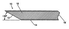
- FIG. 1is a side cross sectional view of the electrosurgical tip of an exemplary electrocautery instrument in accordance with the invention
- FIG. 2is a schematic plan view of a an electrocautery instrument in accordance with a preferred embodiment of the present invention showing the electrosurgical tip within the preferable efficacious range with respect to the target vein;
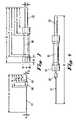
- FIG. 3is a side exploded view of the functional unit of an exemplary electrocautery instrument in accordance with the invention.
- FIG. 4is a side perspective view of the functional unit of the electrocautery instrument as shown in FIG. 3 ;
- FIG. 5is a perspective view of the functional unit installed in the hand piece of an exemplary electrocautery instrument in accordance with the invention.
- FIG. 6is a schematic plan view of an electrocautery instrument hand piece, in the hand of a user, in accordance with a preferred embodiment of the present invention.
- Electrocautery techniquestraditionally consist of a device in which an electric current is used to heat a treatment instrument or probe.
- the heated probecauterizes vessels, thus minimizing blood loss during surgery. Also called thermal cautery, this device does not transfer any electric current to the patient.
- an electrocautery instrument in accordance with the present inventionprovides precision in that the user can be assured of site-specific results without collateral tissue damage.
- the tip of the electrocautery instrumentmay not necessarily be introduced into the target vein, nonspecific collateral tissue damage is minimized as a result of the design of the electrosurgical tip.
- the tippreferably comprises a needle with a preferred diameter of about 0.01 and coated with a biocompatible sheath.
- the necessary characteristic of an acceptable sheathis that it adequately serves as a protective layer that does not inhibit insertion of the tip effectively through the dermis of a patient.
- the sheathhas a thickness of equal to or less than 0.0005′′.
- the sheathmust not only allow adequate tip insertion but must also provide protection to tissue around the target vein.
- the ability of the electrocautery instrument to destroy target veins without causing collateral damage to neighboring tissueis a function of the thickness of the sheath as well as the location of the sheath.
- the sheath of biocompatible materialcoats substantially the entire needle portion of the electrocautery needle so as to prevent the exposure of neighboring tissue to its therapeutics.
- an exemplary electrosurgical needle 10 for an electrocautery instrumentcomprises an exposed tip 12 , where the needle 10 is substantially covered by a biocompatible sheath 14 .
- the needle 10 in accordance with the present inventionis substantially coterminous with the tip.
- the tip 12 of needle 10is beveled to insure that the maximum surface area is coated by the sheath 14 and preventing collateral tissue damage.
- the needle 10is adapted to attach at end 16 to a standard electrocautery unit.
- FIG. 2shows an exemplary electrosurgical needle 10 , in accordance with the present invention, as inserted through the epidermis 20 and into the dermis 24 of a patient.
- the tip 12 of the electrosurgical needle 10does not have to be inserted into the lumen of the target capillary 22 .
- the tip 12is preferably beveled to provide additional accuracy and control.
- An exemplary tip 12is beveled at a 30° angle but other acute angles are acceptable. Effective treatment is achieved when the electrocautery instrument in accordance with the present invention is operated at a preferable frequency between 1.0 MHz to 1.5 MHz.
- the functional unit 30 of an electrocautery instrument in accordance with the present inventioncomprises a replaceable needle 20 having an exposed tip 12 on the working end and a coupling member 28 for operatively and reversibly affixing the needle 10 with the base 31 of the functional member 30 .
- the pieces of the functional unit 30may be coupled together by various conventional means, including but not limited to, snap fitting, threaded mating, male/female connectors, etc.
- the functional unit 30is coupled to an electrosurgical generator via cord 38 that is coupled to the terminal section 32 of the functional unit.
- a preferred electrocautery instrument in accordance with the present inventioncomprises an electrosurgical generator; a longitudinally extending functional unit having first and second ends; the first end of the functional unit operably coupled with the electrosurgical generator and configured to receive electrosurgical current from the electrosurgical generator; the second end of the functional unit terminating with an electrically conductive needle tip for administering the current derived from the electrosurgical generator and a biocompatible sheath that is substantially co-terminal with the conductive tip of the needle.
- the electrosurgical generatorprovides a desirable level of electrical current to the tip of the instrument. Though the desired frequency may be above 1.5 MHz, the present invention is suitably configured to adequately address varices at about between 0.5 MHz and 1.5 MHz.
- an exemplary electrocautery instrumentin accordance with the present invention is adaptable for indication in a variety of protocols.
- an exemplary electrocautery instrumentcan be used to treat vein abnormalities in a patient, by providing an electrocautery instrument; the specially designed tip of the instrument penetrates the skin of the patient.
- the tippreferably comprises an electrically conductive needle tip, which is advanced adjacent to a target vein to be treated. Once the tip is brought within contact of the target vessel, the electrosurgical generator is activated until the vein adjacent the active tip portion is damaged. Afterwards, as with other procedures, the natural regenerative processes of the patient will clear the unsightly veins after the procedure is completed.
- the present inventiongives the user more control and causes less collateral damage.
- the insulation sheathis thinner (between about 0.0001–0.0005 inches) and is substantially co-terminal with the beveled tip.
- an electrocautery instrument in accordance with the present inventionaddresses the limitations of convention spider vein treatments generally and the limitations of the Ellman device in particular.
- the present inventiondoes not require the insertion of the active tip into the target vein; superficial contact is sufficient.
- the active tipis insulated by a sheath that is preferably 0.0005 inches thick, which is operatively distinct from the Ellman device and other devices that require an insulation thickness of 0.0007 inches or greater. This increased thickness is even more crucial when you consider that the insulation layer and the needle it surrounds are both introduced into the target tissue when using the Ellman device. Even without the electrical current, undesirable collateral tissue damage may result if the device is not used properly.
- the insulating sheath of an electrocautery instrument in accordance with the present inventionis substantially co-terminal with the tip of the needle so as to limit collateral tissue damage. Furthermore, the tip of the needle is beveled at an acute angle so as to increase active surface area without exposing adjacent non-target tissue to electrical current. Conversely, the insulation of the Ellman device stops short of the active portion of the needle, and therefore exposes adjacent tissue to electrical current. As an additional limitation of the Ellman device, the active tip is extremely narrow, which adversely affects control and accuracy of use. Moreover, even though the tip is narrow, there is more non-target tissue exposure with Ellman style devices than with the present invention. This is a function of, as discussed above, the insulation terminating short of the needle's active region. Therefore, the present invention is an operable and efficient solution to the limitations of conventional devices.
Landscapes
- Health & Medical Sciences (AREA)
- Surgery (AREA)
- Engineering & Computer Science (AREA)
- Life Sciences & Earth Sciences (AREA)
- Biomedical Technology (AREA)
- Otolaryngology (AREA)
- Nuclear Medicine, Radiotherapy & Molecular Imaging (AREA)
- Plasma & Fusion (AREA)
- Physics & Mathematics (AREA)
- Heart & Thoracic Surgery (AREA)
- Medical Informatics (AREA)
- Molecular Biology (AREA)
- Animal Behavior & Ethology (AREA)
- General Health & Medical Sciences (AREA)
- Public Health (AREA)
- Veterinary Medicine (AREA)
- Surgical Instruments (AREA)
Abstract
Description
- A=31.5
- B=10.5
- C=9.5
- D=6.0
- E=5.0
- F=4.0
- G=47.0
- H=42.0
- I=40.0
- J=24.0
- K=22.0
- L=18.0
- M=4.5
- N=0.3
- O=0.8
- P=6.0
- Q=2.3
- R=75.0
It should be kept in mind that these dimensions are suggested guidelines and should not be construed as limiting if other dimensions would fulfill the objectives of the present invention.
Claims (5)
Priority Applications (4)
| Application Number | Priority Date | Filing Date | Title |
|---|---|---|---|
| US10/243,818US7125406B2 (en) | 2002-09-13 | 2002-09-13 | Electrocautery instrument |
| AU2003270647AAU2003270647A1 (en) | 2002-09-13 | 2003-09-12 | Electrocautery instrument |
| PCT/US2003/028837WO2004024273A1 (en) | 2002-09-13 | 2003-09-12 | Electrocautery instrument |
| US11/537,739US7628790B2 (en) | 2002-09-13 | 2006-10-02 | Method of treating spider veins |
Applications Claiming Priority (1)
| Application Number | Priority Date | Filing Date | Title |
|---|---|---|---|
| US10/243,818US7125406B2 (en) | 2002-09-13 | 2002-09-13 | Electrocautery instrument |
Related Child Applications (1)
| Application Number | Title | Priority Date | Filing Date |
|---|---|---|---|
| US11/537,739ContinuationUS7628790B2 (en) | 2002-09-13 | 2006-10-02 | Method of treating spider veins |
Publications (2)
| Publication Number | Publication Date |
|---|---|
| US20040054370A1 US20040054370A1 (en) | 2004-03-18 |
| US7125406B2true US7125406B2 (en) | 2006-10-24 |
Family
ID=31991741
Family Applications (2)
| Application Number | Title | Priority Date | Filing Date |
|---|---|---|---|
| US10/243,818Expired - LifetimeUS7125406B2 (en) | 2002-09-13 | 2002-09-13 | Electrocautery instrument |
| US11/537,739Expired - LifetimeUS7628790B2 (en) | 2002-09-13 | 2006-10-02 | Method of treating spider veins |
Family Applications After (1)
| Application Number | Title | Priority Date | Filing Date |
|---|---|---|---|
| US11/537,739Expired - LifetimeUS7628790B2 (en) | 2002-09-13 | 2006-10-02 | Method of treating spider veins |
Country Status (3)
| Country | Link |
|---|---|
| US (2) | US7125406B2 (en) |
| AU (1) | AU2003270647A1 (en) |
| WO (1) | WO2004024273A1 (en) |
Cited By (13)
| Publication number | Priority date | Publication date | Assignee | Title |
|---|---|---|---|---|
| US7537595B2 (en) | 2001-12-12 | 2009-05-26 | Tissuelink Medical, Inc. | Fluid-assisted medical devices, systems and methods |
| US7604635B2 (en) | 2000-03-06 | 2009-10-20 | Salient Surgical Technologies, Inc. | Fluid-assisted medical devices, systems and methods |
| US7645277B2 (en) | 2000-09-22 | 2010-01-12 | Salient Surgical Technologies, Inc. | Fluid-assisted medical device |
| US7727232B1 (en) | 2004-02-04 | 2010-06-01 | Salient Surgical Technologies, Inc. | Fluid-assisted medical devices and methods |
| US7811282B2 (en) | 2000-03-06 | 2010-10-12 | Salient Surgical Technologies, Inc. | Fluid-assisted electrosurgical devices, electrosurgical unit with pump and methods of use thereof |
| US7815634B2 (en) | 2000-03-06 | 2010-10-19 | Salient Surgical Technologies, Inc. | Fluid delivery system and controller for electrosurgical devices |
| US7951148B2 (en) | 2001-03-08 | 2011-05-31 | Salient Surgical Technologies, Inc. | Electrosurgical device having a tissue reduction sensor |
| US7998140B2 (en) | 2002-02-12 | 2011-08-16 | Salient Surgical Technologies, Inc. | Fluid-assisted medical devices, systems and methods |
| US8460289B2 (en) | 2005-06-28 | 2013-06-11 | Covidien Ag | Electrode with rotatably deployable sheath |
| US8475455B2 (en) | 2002-10-29 | 2013-07-02 | Medtronic Advanced Energy Llc | Fluid-assisted electrosurgical scissors and methods |
| US10433898B2 (en) | 2015-01-13 | 2019-10-08 | Megadyne Medical Products, Inc. | Tapered precision blade electrosurgical instrument |
| US10433899B2 (en) | 2015-01-13 | 2019-10-08 | Megadyne Medical Products, Inc. | Precision blade electrosurgical instrument |
| US10537667B2 (en) | 2015-01-28 | 2020-01-21 | Ethicon Llc | High temperature material for use in medical devices |
Families Citing this family (24)
| Publication number | Priority date | Publication date | Assignee | Title |
|---|---|---|---|---|
| JP2005533607A (en) | 2002-07-25 | 2005-11-10 | シャーウッド・サービシーズ・アクチェンゲゼルシャフト | Electrosurgical pencil with drag detection |
| US7244257B2 (en)* | 2002-11-05 | 2007-07-17 | Sherwood Services Ag | Electrosurgical pencil having a single button variable control |
| AU2004212990B2 (en)* | 2003-02-20 | 2009-12-10 | Covidien Ag | Motion detector for controlling electrosurgical output |
| US7241294B2 (en)* | 2003-11-19 | 2007-07-10 | Sherwood Services Ag | Pistol grip electrosurgical pencil with manual aspirator/irrigator and methods of using the same |
| US7879033B2 (en) | 2003-11-20 | 2011-02-01 | Covidien Ag | Electrosurgical pencil with advanced ES controls |
| US7503917B2 (en) | 2003-11-20 | 2009-03-17 | Covidien Ag | Electrosurgical pencil with improved controls |
| US7156844B2 (en) | 2003-11-20 | 2007-01-02 | Sherwood Services Ag | Electrosurgical pencil with improved controls |
| US7156842B2 (en) | 2003-11-20 | 2007-01-02 | Sherwood Services Ag | Electrosurgical pencil with improved controls |
| US7445620B2 (en)* | 2005-08-11 | 2008-11-04 | The Cleveland Clinic Foundation | Apparatus and method for protecting nontarget tissue of a patient during electrocautery surgery |
| US7828794B2 (en) | 2005-08-25 | 2010-11-09 | Covidien Ag | Handheld electrosurgical apparatus for controlling operating room equipment |
| US7465312B2 (en)* | 2006-05-02 | 2008-12-16 | Green Medical, Inc. | Systems and methods for treating superficial venous malformations like spider veins |
| US20090326435A1 (en)* | 2006-05-02 | 2009-12-31 | Green Medical, Inc. | Systems and methods for treating superficial venous malformations like varicose or spider veins |
| US20070299431A1 (en)* | 2006-05-02 | 2007-12-27 | Green Medical, Inc. | Systems and methods for treating superficial venous malformations like spider veins |
| US20070260240A1 (en) | 2006-05-05 | 2007-11-08 | Sherwood Services Ag | Soft tissue RF transection and resection device |
| US8506565B2 (en) | 2007-08-23 | 2013-08-13 | Covidien Lp | Electrosurgical device with LED adapter |
| US8235987B2 (en) | 2007-12-05 | 2012-08-07 | Tyco Healthcare Group Lp | Thermal penetration and arc length controllable electrosurgical pencil |
| US8636733B2 (en) | 2008-03-31 | 2014-01-28 | Covidien Lp | Electrosurgical pencil including improved controls |
| US8663218B2 (en)* | 2008-03-31 | 2014-03-04 | Covidien Lp | Electrosurgical pencil including improved controls |
| US8597292B2 (en) | 2008-03-31 | 2013-12-03 | Covidien Lp | Electrosurgical pencil including improved controls |
| US8162937B2 (en) | 2008-06-27 | 2012-04-24 | Tyco Healthcare Group Lp | High volume fluid seal for electrosurgical handpiece |
| US8231620B2 (en) | 2009-02-10 | 2012-07-31 | Tyco Healthcare Group Lp | Extension cutting blade |
| CN102793580B (en)* | 2012-08-17 | 2014-10-22 | 南京大学医学院附属鼓楼医院 | Vascular puncture electro-coagulation needle |
| US11399888B2 (en) | 2019-08-14 | 2022-08-02 | Covidien Lp | Bipolar pencil |
| US11564732B2 (en) | 2019-12-05 | 2023-01-31 | Covidien Lp | Tensioning mechanism for bipolar pencil |
Citations (13)
| Publication number | Priority date | Publication date | Assignee | Title |
|---|---|---|---|---|
| US4321926A (en) | 1979-04-16 | 1982-03-30 | Roge Ralph R | Insertion detecting probe and electrolysis system |
| US4561445A (en)* | 1983-05-25 | 1985-12-31 | Joseph J. Berke | Elongated needle electrode and method of making same |
| US4920968A (en) | 1987-01-20 | 1990-05-01 | Haruo Takase | Needle base with plural needles for subcutaneously applying electric current |
| US5403311A (en)* | 1993-03-29 | 1995-04-04 | Boston Scientific Corporation | Electro-coagulation and ablation and other electrotherapeutic treatments of body tissue |
| US5578029A (en)* | 1994-09-23 | 1996-11-26 | Coherent, Inc. | Method of treating veins |
| US5658282A (en) | 1994-01-18 | 1997-08-19 | Endovascular, Inc. | Apparatus for in situ saphenous vein bypass and less-invasive varicose vein treatment |
| US5695495A (en) | 1995-11-20 | 1997-12-09 | Ellman; Alan G. | Electrosurgical electrode for sclerotherapy |
| US5702387A (en)* | 1995-09-27 | 1997-12-30 | Valleylab Inc | Coated electrosurgical electrode |
| US5792137A (en) | 1995-10-27 | 1998-08-11 | Lacar Microsystems, Inc. | Coagulating microsystem |
| US5944717A (en) | 1997-05-12 | 1999-08-31 | The Regents Of The University Of California | Micromachined electrical cauterizer |
| US6228082B1 (en)* | 1995-11-22 | 2001-05-08 | Arthrocare Corporation | Systems and methods for electrosurgical treatment of vascular disorders |
| US6235027B1 (en) | 1999-01-21 | 2001-05-22 | Garrett D. Herzon | Thermal cautery surgical forceps |
| US6416514B1 (en)* | 1998-08-30 | 2002-07-09 | Moshe Ein-Gal | Electrocoagulation apparatus |
Family Cites Families (2)
| Publication number | Priority date | Publication date | Assignee | Title |
|---|---|---|---|---|
| US6413255B1 (en)* | 1999-03-09 | 2002-07-02 | Thermage, Inc. | Apparatus and method for treatment of tissue |
| US20020165529A1 (en)* | 2001-04-05 | 2002-11-07 | Danek Christopher James | Method and apparatus for non-invasive energy delivery |
- 2002
- 2002-09-13USUS10/243,818patent/US7125406B2/ennot_activeExpired - Lifetime
- 2003
- 2003-09-12AUAU2003270647Apatent/AU2003270647A1/ennot_activeAbandoned
- 2003-09-12WOPCT/US2003/028837patent/WO2004024273A1/ennot_activeApplication Discontinuation
- 2006
- 2006-10-02USUS11/537,739patent/US7628790B2/ennot_activeExpired - Lifetime
Patent Citations (13)
| Publication number | Priority date | Publication date | Assignee | Title |
|---|---|---|---|---|
| US4321926A (en) | 1979-04-16 | 1982-03-30 | Roge Ralph R | Insertion detecting probe and electrolysis system |
| US4561445A (en)* | 1983-05-25 | 1985-12-31 | Joseph J. Berke | Elongated needle electrode and method of making same |
| US4920968A (en) | 1987-01-20 | 1990-05-01 | Haruo Takase | Needle base with plural needles for subcutaneously applying electric current |
| US5403311A (en)* | 1993-03-29 | 1995-04-04 | Boston Scientific Corporation | Electro-coagulation and ablation and other electrotherapeutic treatments of body tissue |
| US5658282A (en) | 1994-01-18 | 1997-08-19 | Endovascular, Inc. | Apparatus for in situ saphenous vein bypass and less-invasive varicose vein treatment |
| US5578029A (en)* | 1994-09-23 | 1996-11-26 | Coherent, Inc. | Method of treating veins |
| US5702387A (en)* | 1995-09-27 | 1997-12-30 | Valleylab Inc | Coated electrosurgical electrode |
| US5792137A (en) | 1995-10-27 | 1998-08-11 | Lacar Microsystems, Inc. | Coagulating microsystem |
| US5695495A (en) | 1995-11-20 | 1997-12-09 | Ellman; Alan G. | Electrosurgical electrode for sclerotherapy |
| US6228082B1 (en)* | 1995-11-22 | 2001-05-08 | Arthrocare Corporation | Systems and methods for electrosurgical treatment of vascular disorders |
| US5944717A (en) | 1997-05-12 | 1999-08-31 | The Regents Of The University Of California | Micromachined electrical cauterizer |
| US6416514B1 (en)* | 1998-08-30 | 2002-07-09 | Moshe Ein-Gal | Electrocoagulation apparatus |
| US6235027B1 (en) | 1999-01-21 | 2001-05-22 | Garrett D. Herzon | Thermal cautery surgical forceps |
Cited By (19)
| Publication number | Priority date | Publication date | Assignee | Title |
|---|---|---|---|---|
| US8048070B2 (en) | 2000-03-06 | 2011-11-01 | Salient Surgical Technologies, Inc. | Fluid-assisted medical devices, systems and methods |
| US7604635B2 (en) | 2000-03-06 | 2009-10-20 | Salient Surgical Technologies, Inc. | Fluid-assisted medical devices, systems and methods |
| US8361068B2 (en) | 2000-03-06 | 2013-01-29 | Medtronic Advanced Energy Llc | Fluid-assisted electrosurgical devices, electrosurgical unit with pump and methods of use thereof |
| US7811282B2 (en) | 2000-03-06 | 2010-10-12 | Salient Surgical Technologies, Inc. | Fluid-assisted electrosurgical devices, electrosurgical unit with pump and methods of use thereof |
| US7815634B2 (en) | 2000-03-06 | 2010-10-19 | Salient Surgical Technologies, Inc. | Fluid delivery system and controller for electrosurgical devices |
| US8038670B2 (en) | 2000-03-06 | 2011-10-18 | Salient Surgical Technologies, Inc. | Fluid-assisted medical devices, systems and methods |
| US7645277B2 (en) | 2000-09-22 | 2010-01-12 | Salient Surgical Technologies, Inc. | Fluid-assisted medical device |
| US7651494B2 (en) | 2000-09-22 | 2010-01-26 | Salient Surgical Technologies, Inc. | Fluid-assisted medical device |
| US7951148B2 (en) | 2001-03-08 | 2011-05-31 | Salient Surgical Technologies, Inc. | Electrosurgical device having a tissue reduction sensor |
| US7537595B2 (en) | 2001-12-12 | 2009-05-26 | Tissuelink Medical, Inc. | Fluid-assisted medical devices, systems and methods |
| US7998140B2 (en) | 2002-02-12 | 2011-08-16 | Salient Surgical Technologies, Inc. | Fluid-assisted medical devices, systems and methods |
| US8475455B2 (en) | 2002-10-29 | 2013-07-02 | Medtronic Advanced Energy Llc | Fluid-assisted electrosurgical scissors and methods |
| US8075557B2 (en) | 2004-02-04 | 2011-12-13 | Salient Surgical Technologies, Inc. | Fluid-assisted medical devices and methods |
| US7727232B1 (en) | 2004-02-04 | 2010-06-01 | Salient Surgical Technologies, Inc. | Fluid-assisted medical devices and methods |
| US8460289B2 (en) | 2005-06-28 | 2013-06-11 | Covidien Ag | Electrode with rotatably deployable sheath |
| US10433898B2 (en) | 2015-01-13 | 2019-10-08 | Megadyne Medical Products, Inc. | Tapered precision blade electrosurgical instrument |
| US10433899B2 (en) | 2015-01-13 | 2019-10-08 | Megadyne Medical Products, Inc. | Precision blade electrosurgical instrument |
| US10537667B2 (en) | 2015-01-28 | 2020-01-21 | Ethicon Llc | High temperature material for use in medical devices |
| US11389572B2 (en) | 2015-01-28 | 2022-07-19 | Cilag Gmbh International | High temperature material for use in medical devices |
Also Published As
| Publication number | Publication date |
|---|---|
| AU2003270647A1 (en) | 2004-04-30 |
| WO2004024273A1 (en) | 2004-03-25 |
| US20070038212A1 (en) | 2007-02-15 |
| US7628790B2 (en) | 2009-12-08 |
| US20040054370A1 (en) | 2004-03-18 |
Similar Documents
| Publication | Publication Date | Title |
|---|---|---|
| US7125406B2 (en) | Electrocautery instrument | |
| US5695495A (en) | Electrosurgical electrode for sclerotherapy | |
| US7422588B2 (en) | Pen-type electrosurgical instrument | |
| US5766165A (en) | Return path monitoring system | |
| US5431649A (en) | Method and apparatus for R-F ablation | |
| US6104952A (en) | Devices for treating canker sores, tissues and methods thereof | |
| US5980516A (en) | Method and apparatus for R-F ablation | |
| US6050993A (en) | Medical device and methods for treating hemorrhoids | |
| US5741249A (en) | Anchoring tip assembly for microwave ablation catheter | |
| US5843080A (en) | Bipolar instrument with multi-coated electrodes | |
| JP2006504472A (en) | Fluid-assisted electrosurgical scissors and method | |
| US7160295B1 (en) | Flexible electrosurgical electrode for treating tissue | |
| US7947037B1 (en) | Cosmetic RF surgery | |
| CN114343826B (en) | Ablation Catheter | |
| US6293944B1 (en) | Combined syringe and electrosurgical electrode for sclerotherapy | |
| JP2024544068A (en) | Systems and methods for tissue puncturing - Patents.com | |
| Schmidt et al. | The bipolar needle for vasectomy. I. Experience with the first 1000 cases | |
| JPH07413A (en) | Catheter system | |
| JPH05253241A (en) | High frequency treatment apparatus | |
| JP3716477B2 (en) | Dipole electrosurgical instrument | |
| KR102038835B1 (en) | Electrode assembly of prostate opreation tool | |
| JP3349372B2 (en) | Microwave surgical instrument | |
| JP2025520473A (en) | Interface Joint | |
| JPH09262244A (en) | Resectoscope | |
| CN120284324A (en) | Insertable surgical electrode front end assembly and electrode thereof |
Legal Events
| Date | Code | Title | Description |
|---|---|---|---|
| AS | Assignment | Owner name:MEDICAL COLLEGE OF GEORGIA RESEARCH INSTITUTE INC, Free format text:ASSIGNMENT OF ASSIGNORS INTEREST;ASSIGNOR:GIVEN, KENNA S.;REEL/FRAME:013409/0027 Effective date:20010908 | |
| STCF | Information on status: patent grant | Free format text:PATENTED CASE | |
| AS | Assignment | Owner name:GIVEN, KENNA S., M.D., GEORGIA Free format text:ASSIGNMENT OF ASSIGNORS INTEREST;ASSIGNOR:MEDICAL COLLEGE OF GEORGIA;REEL/FRAME:020878/0346 Effective date:20080408 | |
| AS | Assignment | Owner name:TRIPPS COURT ENTERPRISES, INC., GEORGIA Free format text:ASSIGNMENT OF ASSIGNORS INTEREST;ASSIGNOR:GIVEN, KENNA S., M.D.;REEL/FRAME:021040/0605 Effective date:20080508 | |
| FPAY | Fee payment | Year of fee payment:4 | |
| AS | Assignment | Owner name:SPIDER VEIN SOLUTIONS, INC., GEORGIA Free format text:CHANGE OF NAME;ASSIGNOR:TRIPPS COURT ENTERPRISES, INC.;REEL/FRAME:026789/0841 Effective date:20101115 | |
| FPAY | Fee payment | Year of fee payment:8 | |
| MAFP | Maintenance fee payment | Free format text:PAYMENT OF MAINTENANCE FEE, 12TH YR, SMALL ENTITY (ORIGINAL EVENT CODE: M2553) Year of fee payment:12 |