US7124755B2 - Respiratory circuit support arm - Google Patents
Respiratory circuit support armDownload PDFInfo
- Publication number
- US7124755B2 US7124755B2US10/037,463US3746301AUS7124755B2US 7124755 B2US7124755 B2US 7124755B2US 3746301 AUS3746301 AUS 3746301AUS 7124755 B2US7124755 B2US 7124755B2
- Authority
- US
- United States
- Prior art keywords
- arm
- bladder
- respiratory
- support
- arm segments
- Prior art date
- Legal status (The legal status is an assumption and is not a legal conclusion. Google has not performed a legal analysis and makes no representation as to the accuracy of the status listed.)
- Expired - Lifetime, expires
Links
- 230000000241respiratory effectEffects0.000titleclaimsabstractdescription141
- 230000000694effectsEffects0.000claimsdescription12
- 230000004913activationEffects0.000claimsdescription3
- 230000029058respiratory gaseous exchangeEffects0.000description5
- 210000002345respiratory systemAnatomy0.000description4
- 230000008901benefitEffects0.000description2
- 238000000034methodMethods0.000description2
- 230000004048modificationEffects0.000description2
- 238000012986modificationMethods0.000description2
- 206010013975DyspnoeasDiseases0.000description1
- 230000009471actionEffects0.000description1
- 230000008859changeEffects0.000description1
- 230000001771impaired effectEffects0.000description1
- 230000006872improvementEffects0.000description1
- 210000004072lungAnatomy0.000description1
- 230000003068static effectEffects0.000description1
- 238000002627tracheal intubationMethods0.000description1
- 238000003466weldingMethods0.000description1
Images


Classifications
- F—MECHANICAL ENGINEERING; LIGHTING; HEATING; WEAPONS; BLASTING
- F16—ENGINEERING ELEMENTS AND UNITS; GENERAL MEASURES FOR PRODUCING AND MAINTAINING EFFECTIVE FUNCTIONING OF MACHINES OR INSTALLATIONS; THERMAL INSULATION IN GENERAL
- F16M—FRAMES, CASINGS OR BEDS OF ENGINES, MACHINES OR APPARATUS, NOT SPECIFIC TO ENGINES, MACHINES OR APPARATUS PROVIDED FOR ELSEWHERE; STANDS; SUPPORTS
- F16M11/00—Stands or trestles as supports for apparatus or articles placed thereon ; Stands for scientific apparatus such as gravitational force meters
- F16M11/20—Undercarriages with or without wheels
- F16M11/2007—Undercarriages with or without wheels comprising means allowing pivoting adjustment
- F16M11/2021—Undercarriages with or without wheels comprising means allowing pivoting adjustment around a horizontal axis
- A—HUMAN NECESSITIES
- A61—MEDICAL OR VETERINARY SCIENCE; HYGIENE
- A61M—DEVICES FOR INTRODUCING MEDIA INTO, OR ONTO, THE BODY; DEVICES FOR TRANSDUCING BODY MEDIA OR FOR TAKING MEDIA FROM THE BODY; DEVICES FOR PRODUCING OR ENDING SLEEP OR STUPOR
- A61M16/00—Devices for influencing the respiratory system of patients by gas treatment, e.g. ventilators; Tracheal tubes
- A61M16/08—Bellows; Connecting tubes ; Water traps; Patient circuits
- F—MECHANICAL ENGINEERING; LIGHTING; HEATING; WEAPONS; BLASTING
- F16—ENGINEERING ELEMENTS AND UNITS; GENERAL MEASURES FOR PRODUCING AND MAINTAINING EFFECTIVE FUNCTIONING OF MACHINES OR INSTALLATIONS; THERMAL INSULATION IN GENERAL
- F16C—SHAFTS; FLEXIBLE SHAFTS; ELEMENTS OR CRANKSHAFT MECHANISMS; ROTARY BODIES OTHER THAN GEARING ELEMENTS; BEARINGS
- F16C11/00—Pivots; Pivotal connections
- F16C11/04—Pivotal connections
- F16C11/10—Arrangements for locking
- F—MECHANICAL ENGINEERING; LIGHTING; HEATING; WEAPONS; BLASTING
- F16—ENGINEERING ELEMENTS AND UNITS; GENERAL MEASURES FOR PRODUCING AND MAINTAINING EFFECTIVE FUNCTIONING OF MACHINES OR INSTALLATIONS; THERMAL INSULATION IN GENERAL
- F16L—PIPES; JOINTS OR FITTINGS FOR PIPES; SUPPORTS FOR PIPES, CABLES OR PROTECTIVE TUBING; MEANS FOR THERMAL INSULATION IN GENERAL
- F16L3/00—Supports for pipes, cables or protective tubing, e.g. hangers, holders, clamps, cleats, clips, brackets
- F16L3/01—Supports for pipes, cables or protective tubing, e.g. hangers, holders, clamps, cleats, clips, brackets for supporting or guiding the pipes, cables or protective tubing, between relatively movable points, e.g. movable channels
- F16L3/015—Supports for pipes, cables or protective tubing, e.g. hangers, holders, clamps, cleats, clips, brackets for supporting or guiding the pipes, cables or protective tubing, between relatively movable points, e.g. movable channels using articulated- or supple-guiding elements
- F—MECHANICAL ENGINEERING; LIGHTING; HEATING; WEAPONS; BLASTING
- F16—ENGINEERING ELEMENTS AND UNITS; GENERAL MEASURES FOR PRODUCING AND MAINTAINING EFFECTIVE FUNCTIONING OF MACHINES OR INSTALLATIONS; THERMAL INSULATION IN GENERAL
- F16M—FRAMES, CASINGS OR BEDS OF ENGINES, MACHINES OR APPARATUS, NOT SPECIFIC TO ENGINES, MACHINES OR APPARATUS PROVIDED FOR ELSEWHERE; STANDS; SUPPORTS
- F16M11/00—Stands or trestles as supports for apparatus or articles placed thereon ; Stands for scientific apparatus such as gravitational force meters
- F16M11/20—Undercarriages with or without wheels
- F16M11/2007—Undercarriages with or without wheels comprising means allowing pivoting adjustment
- F16M11/2035—Undercarriages with or without wheels comprising means allowing pivoting adjustment in more than one direction
- F16M11/2078—Undercarriages with or without wheels comprising means allowing pivoting adjustment in more than one direction with ball-joint
- A—HUMAN NECESSITIES
- A61—MEDICAL OR VETERINARY SCIENCE; HYGIENE
- A61M—DEVICES FOR INTRODUCING MEDIA INTO, OR ONTO, THE BODY; DEVICES FOR TRANSDUCING BODY MEDIA OR FOR TAKING MEDIA FROM THE BODY; DEVICES FOR PRODUCING OR ENDING SLEEP OR STUPOR
- A61M2209/00—Ancillary equipment
- A61M2209/08—Supports for equipment
- A61M2209/082—Mounting brackets, arm supports for equipment
- F—MECHANICAL ENGINEERING; LIGHTING; HEATING; WEAPONS; BLASTING
- F16—ENGINEERING ELEMENTS AND UNITS; GENERAL MEASURES FOR PRODUCING AND MAINTAINING EFFECTIVE FUNCTIONING OF MACHINES OR INSTALLATIONS; THERMAL INSULATION IN GENERAL
- F16M—FRAMES, CASINGS OR BEDS OF ENGINES, MACHINES OR APPARATUS, NOT SPECIFIC TO ENGINES, MACHINES OR APPARATUS PROVIDED FOR ELSEWHERE; STANDS; SUPPORTS
- F16M2200/00—Details of stands or supports
- F16M2200/02—Locking means
- F16M2200/021—Locking means for rotational movement
- F16M2200/022—Locking means for rotational movement by friction
- F—MECHANICAL ENGINEERING; LIGHTING; HEATING; WEAPONS; BLASTING
- F16—ENGINEERING ELEMENTS AND UNITS; GENERAL MEASURES FOR PRODUCING AND MAINTAINING EFFECTIVE FUNCTIONING OF MACHINES OR INSTALLATIONS; THERMAL INSULATION IN GENERAL
- F16M—FRAMES, CASINGS OR BEDS OF ENGINES, MACHINES OR APPARATUS, NOT SPECIFIC TO ENGINES, MACHINES OR APPARATUS PROVIDED FOR ELSEWHERE; STANDS; SUPPORTS
- F16M2200/00—Details of stands or supports
- F16M2200/06—Arms
- F16M2200/065—Arms with a special structure, e.g. reinforced or adapted for space reduction
- Y—GENERAL TAGGING OF NEW TECHNOLOGICAL DEVELOPMENTS; GENERAL TAGGING OF CROSS-SECTIONAL TECHNOLOGIES SPANNING OVER SEVERAL SECTIONS OF THE IPC; TECHNICAL SUBJECTS COVERED BY FORMER USPC CROSS-REFERENCE ART COLLECTIONS [XRACs] AND DIGESTS
- Y10—TECHNICAL SUBJECTS COVERED BY FORMER USPC
- Y10S—TECHNICAL SUBJECTS COVERED BY FORMER USPC CROSS-REFERENCE ART COLLECTIONS [XRACs] AND DIGESTS
- Y10S128/00—Surgery
- Y10S128/26—Cannula supporters
Definitions
- Ailments that affect the respiratory systemcan occur in people of any age group. These ailments can range anywhere from a temporary condition that requires minor treatment to a permanent disability that requires constant respiratory treatment.
- Endotracheal intubation tubesare used primarily for the provision of an artificial airway in a patient's respiratory system for the passage of gasses and objects to and from the patient.
- Endotracheal tubesare typically rigid or semi-rigid cylindrical tubing that may extend from outside of the patient into the patient's lungs. Surgical instruments are then passed through this tubing into the patient's respiratory system in order to perform various medical procedures.
- Ventilatorsare commonly used to provide artificial respiration to patients in such circumstances. Ventilators are typically connected to a manifold of the breathing circuit to provide for artificial respiration of the patient. Ventilators may be configured so as to completely control the breathing of a patient, or configured such that the ventilator responds only when a patient has labored breathing to a predetermined extent.
- a respiratory circuitSince a respiratory circuit has components located both on the inside and outside of a patient, the support and stability of a respiratory circuit is important in maintaining an optimal level of performance of the respiratory circuit and related components. It is sometimes the case that the tubing of a ventilator or even the tubing of a respiratory circuit is not rigid and needs to be supported. Also, it is often the case that a patient must be moved during the normal course of treatment, necessitating a change in position of the respiratory circuit. Additionally, even rigid or semi-rigid tubing in a respiratory circuit may need to be supported in order to provide for proper positioning of the tubing in relation to a patient or to provide for optimum patient comfort. In these circumstances, a support arm is sometimes used in order to support components of the respiratory circuit.
- support armshave been located on a ventilator unit and extended therefrom in order to support tubing of the respiratory circuit.
- These support armsare typically provided with several joints that allow the support arm to enjoy a full range of motion.
- the tubing of the respiratory circuitis attached to one end of the support arm. This attachment may be a sliding support or a static connection.
- a caregivermay then manipulate the support arm such that the tubing is properly positioned.
- Support armsare typically provided with adjustment screws located at the various points of movement. A caregiver may manually tighten these adjustment screws in order to lock the support arm in the desired location. It is therefore the case that support arms typically require the caregiver to manually tighten and loosen from between two and four adjustment screws in order to properly manipulate and lock the support arm in the desired position. This adjustment requires the use of two hands by a caregiver.
- the present inventionis an improvement upon support arms that are used in supporting a respiratory circuit.
- the present inventionprovides for a support arm for use in a respiratory circuit.
- the support armincludes a plurality of arm segments that are movably connected with one another such that the arm segments are adjustable with respect to one another.
- At least one inflatable bladderis provided that is operably disposed at a point of connection between at least two of the arm segments. Inflation of the bladder causes the arm segments to be locked into position with respect to one another. Deflation of the bladder causes the arm segments to be released and therefore positionable with respect to one another.
- a respiratory support memberthat is attached to one of the arm segments. The respiratory support member is configured for engaging and support a component of the respiratory circuit.
- a support armas previously discussed where at least one of the arm segments may have a flexible section. Also, a least one of the inflatable bladders is located in the flexible section of the arm segment. The bladder is inflatable to rigidify the flexible section.
- Also provided for in the present inventionis an embodiment of a support member as previously discussed where the bladder is within at least one of the arm segments.
- the present inventionalso includes an embodiment of a support arm for use with a respiratory circuit that has a plurality of arm segments. At least one of the arm segments is a rigid member, and at least one of the arm segments has a flexible section.
- the arm segmentsare connected to one another by swivel joints to allow the arm segments to swivel with respect to one another.
- a bladderis located inside of the arm segments. The bladder may be continuous through the arm segments. The bladder is inflatable in order to effect a locking of the arm segments with respect to one another.
- a respiratory support memberis also provided and may be attached to one of the arm segments and is adjustable with respect to the arm segment. Inflation of the bladder causes a locking of the respiratory support member and prevents adjustment of the respiratory support member with respect to the arm segment.
- the respiratory support memberis configured for engaging a component of the respiratory circuit.
- the present inventionfurther provides for a support arm as immediately discussed where the support arm has three arm segments. Two of the arm segments are rigid and one of the arm segments has a flexible section. The respiratory support member is attached to the arm segment having a flexible section.
- the present inventionincludes a support arm for use with a respiratory circuit as previously discussed where one of the arm segments may have a control member attached thereto.
- the control memberis located proximate to the respiratory support member. Activation of the control member causes deflation of the bladder and unlocking of the arm segments to allow a user to manipulate the arm segments.
- a support armfor use with a respiratory circuit as previously discussed where an embodiment of the respiratory support member has a ball and socket connection. This connection is used for effecting adjustment of the respiratory support member in relation to the arm segment.
- the support armhas three segments. Two of the arm segments are a rigid member, and the other has a flexible section. One of the rigid arm segments is adjustably connected on one end to a ventilator. The two rigid arm segments are adjustably connected to one another by a first swivel joint. One of the rigid arm segments and the arm segment having the flexible section are adjustably connected to one another by a second swivel joint. The flexible section is formed by a corrugated member. Further, a respiratory support member is connected to the arm segment that has the flexible section. The respiratory support member has one end configured for engagement with a tube of a respiratory circuit to support the tube. The respiratory support member has a pivot connection to allow for adjustment of the respiratory support member.
- a flexible bladderis present.
- the bladderis disposed through the arm segments. Inflation of the bladder effects a locking of the swivel joints and the flexible section to cause a locking of the arm segments and prevent relative motion between the arm segments. Inflation of the bladder effects a locking of the pivot connection of the respiratory support member to prevent adjustment of the respiratory support member.
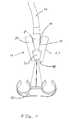
- FIG. 1is a perspective view of an exemplary embodiment of a support arm of the present invention.
- the support armis shown supporting a component of a respiratory circuit.
- FIG. 2is a perspective view of an exemplary embodiment of a respiratory support member of the present invention.
- the respiratory support memberhas a respiratory support adjustment handle attached thereon.
- FIG. 3is an exploded perspective view of the respiratory support member shown in FIG. 2 .
- FIG. 4is a partial cross-sectional view of an exemplary embodiment of a flexible section in accordance with the present invention.
- the flexible sectionis free to move, and an uninflated bladder runs therethrough.
- FIG. 5is a view of the flexible section shown in FIG. 4 with the bladder inflated. Once inflated, the flexible section is fixed and prevented from moving.
- FIG. 6is an exploded assembly view of an exemplary embodiment of a support arm in accordance with the present invention.
- the drawingshows the swivel joints that connect the support arms.
- FIG. 7is an assembled perspective view of the exemplary embodiment shown in FIG. 6 .
- FIG. 8is a perspective view of an exemplary embodiment of a respiratory support member in accordance with the present invention.
- FIG. 9is an exploded assembly view of the embodiment of the respiratory support member shown in FIG. 8 .
- FIG. 10is a perspective view of an exemplary embodiment of a respiratory support member in accordance with the present invention. The view shows the respiratory support member having a ball and socket connection in a disengaged state.
- FIG. 11is a perspective view of the respiratory support member shown in FIG. 10 .
- the drawingshows a bladder acting on sections of the respiratory support member to engage the ball and socket connection and hold the respiratory circuit gripping member.
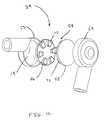
- FIG. 12is an exploded assembly view of an exemplary embodiment of a swivel joint in accordance with the present invention.
- the drawingshows a bladder disposed within swivel cups and configured to engage a snap ring configuration.
- FIG. 13is an exploded assembly view of the swivel joint shown in FIG. 12 .
- the drawingshows the swivel joint at a different angle than that shown in FIG. 12 .
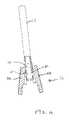
- FIG. 14is a partial cross-sectional view of an embodiment of a respiratory support member in accordance with the present invention.
- a bladderis shown in an uninflated state, and two sections of the respiratory support member are not engaged.
- FIG. 15is a partial cross-sectional view of the exemplary embodiment of the respiratory support member shown in FIG. 14 .
- the bladderis shown in an inflated state engaging the two sections of the respiratory support member.
- FIG. 1An exemplary embodiment of a support arm 10 in accordance with the present invention is shown in FIG. 1 .
- the support arm 10is designed to be attached to a ventilator (not shown). However, it is to be understood that the support arm 10 may in other exemplary embodiments be attached to objects other than a ventilator.
- the support arm 10is configured to hold a respiratory circuit component 28 . In order to properly position the support arm 10 such that it may support the respiratory circuit component 28 , the support arm 10 is constructed of a series of arm segments 12 . Although shown as having three arm segments 12 in FIG. 1 , it is to be understood that the support arm 10 may be constructed of any number of arm segments 12 .
- the arm segments 12are designed to be movable with respect to one another such that the support arm 10 can be articulated and moved into any desired position.
- any manner of suitable swivel joints 24are provided that connect the arm segments.
- a first arm segment 100is present and is connected on one end to a ventilator connection adjustment 56 .
- the ventilator connection adjustment 56is provided with a ventilator connection adjustment handle 40 .
- the ventilator connection adjustment handle 40may be loosened to in order to allow for adjustment of the first arm segment 100 with respect to a ventilator connection member 32 .
- the ventilator connection member 32is connected to a ventilator.
- the ventilator connection adjustment 56may therefore allow the first arm segment 100 to move vertically, horizontally, or rotationally with respect to the ventilator connection member 32 .
- the other end of the first arm segment 100is connected to a first swivel joint 110 which is also connected to an end of a second arm segment 102 .
- a point of connection 58is defined between the first arm segment 100 and the second arm segment 102 .
- the first swivel joint 110allows for relative rotational movement between the first arm segment 100 and the second arm segment 102 .
- the first arm segment 100 and second arm segment 102are both rigid members.
- the second arm segment 102is likewise connected to a second swivel joint 112 that is also connected to a third arm segment 104 .
- the second swivel joint 112allows for relative rotational movement between the second arm segment 102 and the third arm segment 104 .
- the second arm segment 102 and the third arm segment 104define a point of connection 58 .
- the third arm segment 104has a flexible section 18 that runs along a part of the length of the third arm segment 104 .
- the flexible section 18allows for the third arm segment 104 to be more precisely adjusted during the adjustment of the support arm 10 .
- the flexible section 18is connected on one end thereof to a respiratory support member 16 .
- the respiratory support member 16is connected to a respiratory circuit gripping member 50 .
- the respiratory circuit gripping member 50engages a tube 46 of the respiratory circuit 28 and positions and supports the tube 46 in the proper location.
- One advantage of a particular embodiment of the present inventionresides in having a user adjust the support arm 10 to a desired position using only one hand. Once placed in the proper position for the support of a respiratory circuit 28 , the user may then use a control member 20 to lock the support arm 10 into the desired position.
- the control member 20is located on the third arm segment 104 . However, it is to be understood that in other exemplary embodiments of the present invention, the control member 20 may be placed on locations other than the arm segments 12 . However, locating the control member 20 on the third arm segment 104 and proximate to the respiratory support member 16 allows for the user to activate the control member 20 without having to move his or her hand off of the respiratory support member 16 . In other words, the user may position and lock the support arm 10 by the use of only one hand.
- the control member 20is equipped with an inflation button 34 and a deflation button 36 .
- the inflation button 34 and deflation button 36are used to control the inflation and deflation of a bladder 14 that is not shown in FIG. 1 , but which runs through the swivel joints 24 , the flexible section 18 , and the arm segments 12 .
- inflation of the bladder 14causes the swivel joints 24 and the flexible section 18 to lock in their present position and prevents the support arm 10 from moving. Deflation of the bladder 14 causes these members to again become movable and flexible. Therefore, the support arm 10 of the present invention uses a bladder 14 to control the locking and unlocking of the support arm 10 .
- FIG. 4shows an exemplary embodiment of a section of the flexible section 18 in accordance with the present invention.
- the flexible section 18is a corrugated member 44 that is composed of corrugated tube 26 which has a series of C-shaped interconnected members 42 .
- the interconnection of the C-shaped interconnected members 42allows for the corrugated tube 26 to be flexible and moveable to a desired position.
- the bladder 14is shown in an uninflated state running through the interior of the corrugated tube 26 .
- FIG. 5shows the flexible section 18 as in FIG. 4 , however, the bladder 14 is shown in an inflated state. Once inflated, the bladder 14 pushes against the C-shaped interconnected members 42 and urges them against one another. This urging locks the C-shaped interconnected members 42 against one another and prevents movement of the corrugated tube 26 . Therefore, FIG. 5 shows the flexible section 18 in a locked configuration.
- FIG. 2shows an exemplary embodiment of a respiratory support member 16 in accordance with the present invention.
- the respiratory support member 16includes two sections 22 movably connected to one another by a screw 52 , as shown in FIG. 3 , and a respiratory support adjustment handle 38 .
- a pivot connection 48is shown being formed by a ball and socket connection 30 .
- This connectionallows for the adjustment of the respiratory circuit gripping member 50 .
- the respiratory support adjustment handle 38may be loosened such that the respiratory circuit gripping member 50 is removable from the respiratory support member 16 .
- the respiratory support adjustment handle 38may be tightened so that the ball and socket connection 30 is engaged and prevented from allowing the respiratory circuit gripping member 50 to move.
- the bladder 14may extend into the respiratory support member 16 .
- the bladder 14When inflated, the bladder 14 is urged against both sections 22 of the respiratory support member 16 . This causes the two sections 22 to pivot and firmly engage the ball and socket connection 30 and prevent the respiratory circuit gripping member 50 from moving. Therefore, the locking of the respiratory circuit gripping member 50 into place may be accomplished through the use of a first adjustment by the respiratory support adjustment handle 38 , and then further securedly locked into place via inflation of the bladder 14 .
- FIGS. 10 and 11more particularly demonstrate the locking of the ball and socket connection 30 .
- FIG. 10shows an exemplary embodiment of the respiratory support member 16 in accordance with the present invention. Here as shown for clarity, the two sections 22 of the respiratory support member 16 do not engage the ball of the ball and socket connection 30 . In one exemplary embodiment of the present invention, the sections 22 loosedly engage the ball of the ball and socket connection 30 even before inflation of the bladder 14 . The pivot connection 48 is thus loosedly engaged and the respiratory circuit gripping member 50 is free to move.
- FIG. 11shows the respiratory support member 16 of FIG. 10 where the pivot connection 48 is engaged and prevented from moving.
- the arm segment 12is provided with two apertures 60 .
- the bladder 14is present within the arm segment 12 , and inflation thereof forces the bladder 14 to move out of the apertures 60 .
- the inflated bladder 14then contacts both of the sections 22 of the respiratory support member 16 and pivots the two sections onto the ball of the ball and socket connection 30 . This creates a locking force on the ball and socket connection 30 and hence results in a locking of the respiratory circuit gripping member 50 .
- FIG. 14shows the bladder 14 in an uninflated state and the sections 22 of the respiratory support member 16 in an unlocked configuration.
- FIG. 15shows the bladder 14 in an inflated state and extending through the apertures 60 to engage the two sections 22 of the respiratory support member 16 .
- the two sections 22 of the respiratory support member 16are now in a locked configuration.
- FIG. 6shows another exemplary embodiment of a support arm 10 in accordance with the present invention.
- a third swivel joint 114is present and is connected to the first arm segment 100 .
- a fourth arm segment 106is also connected to the ventilator connection member 32 . Therefore, it is to be understood that the present invention includes various exemplary embodiments that consist of any number of swivel joints 24 and arm segments 12 .
- FIG. 6discloses an exemplary embodiment of the support arm 10 that does not have a respiratory support adjustment handle 38 that is used to adjust the respiratory support member 16 .
- a respiratory support member 16 that does not have the respiratory support adjustment handle 38is shown in more detail in FIG. 8 .
- the pivot connection 48may be formed by simply having a frictional engagement of the ball and socket connection 30 .
- the two sections 22 of the respiratory support member 16do not have to be engaged by a bladder 14 .
- the two sections 22are adhered to one another by commonly known techniques such as adhesion or sonic welding.
- the respiratory support member 16can be a purely mechanical connection and does not need to have a bladder 14 for its proper operation in other exemplary embodiments of the present invention.
- FIG. 7shows this type of respiratory support member 16 being used on a support arm 10 in another exemplary embodiment of the present invention.
- the support arm 10 shown in FIG. 7is the assembled support arm 10 of FIG. 6 .
- inflation of the bladder 14will only effect a locking of the swivel joints 24 and the flexible section 18 , and not the locking of the respiratory support member 16 .
- the third arm segment 104does not need to have a flexible section 18 included thereon.
- other exemplary embodiments of the present inventionmay include a third arm segment 104 that is completely rigid.
- the flexible section 18does not have to be a corrugated tube 26 , but may be made flexible via other means commonly known in the art.
- FIG. 12shows an exploded view of the swivel joint 24 in accordance with the present invention.
- the swivel joint 24has a snap ring configuration 54 that includes a first snap ring 66 and a second snap ring 68 .
- the first snap ring 66is configured to be disposed within a first swivel cup 62
- the second snap ring 68is configured to be disposed within a second swivel cup 64 .
- the bladder 14is disposed within the first swivel cup 62 and also within the second swivel cup 64 , although this cannot be seen in FIG. 12 .
- the first and second snap rings 66 and 68do not engage one another and are free to rotate with respect to one another. In effect, the swivel joint 24 is free to swivel when the bladder 14 is uninflated.
- the first snap ring 66is provided with a series of first snap ring projections 70
- the second snap ring 68is provided with a series of second snap ring projections 72 .
- the configurations of the first and second snap ring projections 70 and 72are designed such that they intermesh with one another when the first and second snap rings 66 and 68 are urged against one another. This intermeshing causes a locking force between the first and second snap rings 66 and 68 . This locking force therefore prevents the swivel joint 24 from swiveling and hence locks the arm segments 12 in place.
- FIG. 13shows the swivel joint 24 of FIG. 12 from a different angle.
- other exemplary embodiments of the present inventioninclude a swivel joint 24 that has the bladder 14 disposed within only one of the swivel cups 62 or 64 .
- other exemplary embodiments of the present inventionmay include a configuration of the swivel joint 24 where the bladder 14 is continuous through the swivel joint 24 .
- the bladder 14may for instance pass through the center of both the first and second snap rings 66 and 68 .
- FIGS. 12 and 13are only one such configuration, and others are conceivable within the present invention.
- exemplary embodiments of the present inventionmay include a configuration where the bladder 14 is continuous throughout all of the arm segments 12 , the swivel joints 24 , the flexible section 18 , and into the respiratory support member 16 . Additionally, other exemplary embodiments may include configurations where the bladder 14 is present within the swivel joints 24 , the flexible section 18 , and the respiratory support member 16 and is connected to all of these sections via tubes through arm segments 12 . In essence, exemplary embodiments of the present invention may include a bladder 14 that is either one or several pieces. Another exemplary embodiment of the present invention exists where the bladder 14 is outside of the arm segments 12 and wraps around the swivel joints 24 to lock them in place.
- the pressure used to inflate the bladder 14may be provided by the ventilator through the ventilator connection member 32 .
- the gas source used to inflate the bladder 14is provided by the compressor in the ventilator.
- other gas sourcesmay be utilized in order to inflate the bladder 14 .
- the bladder 14allows for the user to manipulate and then lock the support arm 10 into place without having to manually tighten the swivel joints 24 . Such an arrangement is provided when single handed operation of the support arm 10 is desired.
Landscapes
- Engineering & Computer Science (AREA)
- General Engineering & Computer Science (AREA)
- Mechanical Engineering (AREA)
- Health & Medical Sciences (AREA)
- Life Sciences & Earth Sciences (AREA)
- Biomedical Technology (AREA)
- Heart & Thoracic Surgery (AREA)
- Hematology (AREA)
- Anesthesiology (AREA)
- Animal Behavior & Ethology (AREA)
- General Health & Medical Sciences (AREA)
- Public Health (AREA)
- Veterinary Medicine (AREA)
- Pulmonology (AREA)
- Emergency Medicine (AREA)
- Respiratory Apparatuses And Protective Means (AREA)
Abstract
Description
Claims (28)
Priority Applications (4)
| Application Number | Priority Date | Filing Date | Title |
|---|---|---|---|
| US10/037,463US7124755B2 (en) | 2001-12-21 | 2001-12-21 | Respiratory circuit support arm |
| PCT/US2002/031131WO2003057294A1 (en) | 2001-12-21 | 2002-09-27 | Respiratory circuit support arm |
| AU2002337785AAU2002337785A1 (en) | 2001-12-21 | 2002-09-27 | Respiratory circuit support arm |
| MXPA04005970AMXPA04005970A (en) | 2001-12-21 | 2002-09-27 | Respiratory circuit support arm. |
Applications Claiming Priority (1)
| Application Number | Priority Date | Filing Date | Title |
|---|---|---|---|
| US10/037,463US7124755B2 (en) | 2001-12-21 | 2001-12-21 | Respiratory circuit support arm |
Publications (2)
| Publication Number | Publication Date |
|---|---|
| US20030116167A1 US20030116167A1 (en) | 2003-06-26 |
| US7124755B2true US7124755B2 (en) | 2006-10-24 |
Family
ID=21894485
Family Applications (1)
| Application Number | Title | Priority Date | Filing Date |
|---|---|---|---|
| US10/037,463Expired - LifetimeUS7124755B2 (en) | 2001-12-21 | 2001-12-21 | Respiratory circuit support arm |
Country Status (4)
| Country | Link |
|---|---|
| US (1) | US7124755B2 (en) |
| AU (1) | AU2002337785A1 (en) |
| MX (1) | MXPA04005970A (en) |
| WO (1) | WO2003057294A1 (en) |
Cited By (28)
| Publication number | Priority date | Publication date | Assignee | Title |
|---|---|---|---|---|
| US20070185376A1 (en)* | 2002-03-11 | 2007-08-09 | Wilson Roger F | System and method for positioning a laparoscopic device |
| US20080034502A1 (en)* | 2004-05-12 | 2008-02-14 | John Robert Copeland | Lateral Support for an Operating Table |
| US20080078397A1 (en)* | 2006-09-28 | 2008-04-03 | Ronald Scott | Hose support system |
| WO2007149734A3 (en)* | 2006-06-21 | 2008-08-21 | Sonotech Llc | Portable support kit for positioning items over bedding |
| US20080236588A1 (en)* | 2007-03-26 | 2008-10-02 | Braebon Medical Corporation | Support device for respiratory interface |
| US20090227874A1 (en)* | 2007-11-09 | 2009-09-10 | Eigen, Inc. | Holder assembly for a medical imaging instrument |
| US20090247819A1 (en)* | 2004-04-02 | 2009-10-01 | Wilson Roger F | System and method for positioning a laparoscopic device |
| US20100122699A1 (en)* | 2008-11-17 | 2010-05-20 | The Metrohealth System | Combination lung ventilation and mucus clearance apparatus and method |
| US20100159415A1 (en)* | 2008-11-23 | 2010-06-24 | Tom Benfield | Dental delivery system |
| US20110140471A1 (en)* | 2009-12-11 | 2011-06-16 | Ned Suesse | Folding Motorcycle Mirror |
| US20120168571A1 (en)* | 2010-11-08 | 2012-07-05 | Dale Medical Products, Inc. | Endotracheal tube holder |
| US20120199716A1 (en)* | 2010-06-23 | 2012-08-09 | Erica Youngblood | Method and System for Luggage Connector |
| US20120312937A1 (en)* | 2011-06-09 | 2012-12-13 | Bruce Weber | Portable and Storable Piñata Stand |
| US20140361584A1 (en)* | 2013-06-07 | 2014-12-11 | Neutral Posture, Inc. | Seating Assembly Having A Seat-Mounted Attachment Assembly For Adjustable Extension Arm |
| US20150238377A1 (en)* | 2014-02-21 | 2015-08-27 | Wali Muhammad | Patient Bedside System Support Device |
| US9126005B1 (en) | 2012-04-21 | 2015-09-08 | Rebecca C. Blaylock | Anesthesia breathing circuit tube support |
| US9133982B1 (en)* | 2014-07-29 | 2015-09-15 | Erika Valdez | Articulated computer mounting system |
| US9180262B2 (en) | 2012-05-15 | 2015-11-10 | JettStream, Inc. | Delivery of nebulized medicines |
| US9433736B2 (en) | 2013-07-03 | 2016-09-06 | JettStream, Inc. | Positionable elongated members with multi-axis joints |
| US9526856B2 (en) | 2011-12-15 | 2016-12-27 | The Board Of Trustees Of The Leland Stanford Junior University | Devices and methods for preventing tracheal aspiration |
| US9770194B2 (en) | 2013-11-05 | 2017-09-26 | Ciel Medical, Inc. | Devices and methods for airway measurement |
| US9795752B2 (en) | 2012-12-03 | 2017-10-24 | Mhs Care-Innovation, Llc | Combination respiratory therapy device, system, and method |
| US20180043118A1 (en)* | 2015-03-21 | 2018-02-15 | Smiths Medical International Limited | Tracheostomy tube assemblies |
| US20180111281A1 (en)* | 2010-08-11 | 2018-04-26 | Thomas J. Bucco | Razor with cutting blade rotatable about multiple axes |
| US20220373126A1 (en)* | 2021-05-24 | 2022-11-24 | Ningbo Tlingt Technology Co., Ltd. | Articulated structure and suspension arm stand having the same |
| US11564770B2 (en) | 2020-09-02 | 2023-01-31 | Nuvasive, Inc. | Surgical systems |
| US20240245030A1 (en)* | 2021-05-25 | 2024-07-25 | Jh & Pm Solutions Ltd | Milking cluster pipe support |
| US12080401B2 (en) | 2012-12-03 | 2024-09-03 | Metrohealth Ventures Llc | Combination respiratory therapy device, system and method |
Families Citing this family (11)
| Publication number | Priority date | Publication date | Assignee | Title |
|---|---|---|---|---|
| CH698192B1 (en)* | 2005-06-16 | 2009-06-15 | Baitella Ag | Pendulum head. |
| DE102007006892A1 (en) | 2007-02-13 | 2008-08-14 | University Of Dundee | Holding device for medical purposes, has joint with two joint parts, which has meshed bosh element in warp connection with one another and mutual bosh elements are aligned perpendicular to support arm |
| WO2013087892A1 (en)* | 2011-12-16 | 2013-06-20 | Chordate Medical Ag | Double stimulation |
| US10143818B2 (en) | 2013-01-22 | 2018-12-04 | Fisher & Paykel Healthcare Limited | Dual-connector wye piece |
| WO2015171830A1 (en)* | 2014-05-06 | 2015-11-12 | The Johns Hopkins University | An adjustable surgical retraction system |
| WO2016043604A1 (en)* | 2014-09-17 | 2016-03-24 | Fisher & Paykel Healthcare Limited | Connectors for respiratory assistance systems |
| AU2018290190B2 (en) | 2017-06-23 | 2024-06-06 | Fisher & Paykel Healthcare Limited | Connectors for respiratory assistance systems |
| JP7049919B2 (en)* | 2018-05-29 | 2022-04-07 | 日本光電工業株式会社 | Fixtures and ventilators |
| US12083273B1 (en)* | 2020-09-09 | 2024-09-10 | SafER Medical Products, LLC | Vacuum shield assembly for attachment to medical masks |
| CN113983314B (en)* | 2021-10-26 | 2023-06-30 | 日照天宇勘察测绘有限公司 | High engineering survey and drawing of stability is with support base |
| CN115056205B (en)* | 2022-07-21 | 2024-06-07 | 西安国际医学中心有限公司 | Anti-falling mechanical lower limb |
Citations (52)
| Publication number | Priority date | Publication date | Assignee | Title |
|---|---|---|---|---|
| US2419860A (en) | 1943-03-30 | 1947-04-29 | Miguel A Urrutia | Adjustable pipe support |
| US3638973A (en) | 1969-06-04 | 1972-02-01 | Charles Ellis Poletti | Joint means for use in work supporting arm |
| US3971538A (en)* | 1975-09-16 | 1976-07-27 | Marvich Jack M | Surgical instrument support |
| US4020834A (en) | 1975-05-16 | 1977-05-03 | Bird F M | Respirator and method |
| US4166602A (en)* | 1978-05-18 | 1979-09-04 | Pennwalt Corporation | Counterbalancing mechanism for X-ray tubeheads |
| US4393728A (en) | 1979-03-16 | 1983-07-19 | Robotgruppen Hb | Flexible arm, particularly a robot arm |
| US4402481A (en)* | 1981-02-27 | 1983-09-06 | Mitutoyo Mfg. Co., Ltd. | Articulated device for service component |
| US4427382A (en) | 1981-03-13 | 1984-01-24 | Kaltenbach & Voigt Gmbh & Co. | Dental equipment stand |
| US4466307A (en)* | 1980-09-14 | 1984-08-21 | Dainichi Kiko Kabushiki Kaisha | Industrial robot |
| US4491435A (en)* | 1983-07-18 | 1985-01-01 | Automated Medical Products Corporation | Jointed stand |
| US4494417A (en) | 1979-03-16 | 1985-01-22 | Robotgruppen Hb | Flexible arm, particularly a robot arm |
| US4502478A (en) | 1983-04-04 | 1985-03-05 | Lifton Lester J | Medical instrument mouth guard |
| USD279378S (en) | 1982-06-09 | 1985-06-25 | Stalvall & Larsson Forsaljnings AB. | Balance arm for supporting working tools |
| US4564179A (en)* | 1984-04-12 | 1986-01-14 | Hollingsworth Ashley J | Articulated support arm apparatus |
| US4645156A (en)* | 1981-11-09 | 1987-02-24 | Karapita Alexander D | Suspension system |
| US4657217A (en) | 1984-12-10 | 1987-04-14 | Siemens Aktiengesellschaft | Parallelogram bracket assembly with a force balancing mechanism |
| DE3703441A1 (en) | 1987-02-05 | 1988-08-18 | Lang Volker | Respiration hose suspension equipment - comprises three guide bars at set angles with hose clips |
| US4826432A (en) | 1986-09-08 | 1989-05-02 | Roseiro Antonio H R | Dental apparatus for odontopediatrics |
| US4863133A (en)* | 1987-05-26 | 1989-09-05 | Leonard Medical | Arm device for adjustable positioning of a medical instrument or the like |
| US4901967A (en) | 1986-07-15 | 1990-02-20 | The Cleveland Clinic Foundation | Patient equipment transport and support system |
| US4954799A (en) | 1989-06-02 | 1990-09-04 | Puritan-Bennett Corporation | Proportional electropneumatic solenoid-controlled valve |
| DE9014848U1 (en) | 1990-10-26 | 1991-02-07 | Carl Heyer GmbH, 5427 Bad Ems | Device on inhalation devices with a container holder for storing a liquid container |
| US5014693A (en) | 1989-10-25 | 1991-05-14 | St. Luke's Episcopal Hospital | Ceiling-mounted gas delivering unit for use in a catheter laboratory |
| US5161525A (en) | 1990-05-11 | 1992-11-10 | Puritan-Bennett Corporation | System and method for flow triggering of pressure supported ventilation |
| US5170790A (en) | 1990-04-06 | 1992-12-15 | Technomed International | Arm having an end movable in translation, and therapeutic treatment apparatus constituting an application thereof |
| US5184365A (en) | 1990-12-07 | 1993-02-09 | Trustees Of Boston University | Method and apparatus of a positioning system for airway management |
| US5231981A (en) | 1991-03-20 | 1993-08-03 | N.A.D., Inc. | Display panel with pistol grip for use with anesthesia apparatus |
| US5263478A (en) | 1991-05-09 | 1993-11-23 | Ballard Medical Products | Endotracheal tube insertion and positioning apparatus |
| US5271389A (en) | 1992-02-12 | 1993-12-21 | Puritan-Bennett Corporation | Ventilator control system that generates, measures, compares, and corrects flow rates |
| US5339807A (en) | 1992-09-22 | 1994-08-23 | Puritan-Bennett Corporation | Exhalation valve stabilizing apparatus |
| US5368019A (en) | 1992-12-16 | 1994-11-29 | Puritan-Bennett Corporation | System and method for operating a respirator compressor system under low voltage conditions |
| US5380338A (en) | 1992-09-03 | 1995-01-10 | Minnesota Scientific, Inc. | Laparoscope holder with rotatable gripping pads |
| US5390666A (en) | 1990-05-11 | 1995-02-21 | Puritan-Bennett Corporation | System and method for flow triggering of breath supported ventilation |
| US5413095A (en) | 1994-04-15 | 1995-05-09 | Arrow Precision Products, Inc. | Mouthpiece with oxygen receiving and directing structure |
| EP0683016A1 (en) | 1994-05-18 | 1995-11-22 | D.T.I. Dr. TRIPPE INGENIEURGES. mbH. | Supporting system for a flexible arm whose elements can be moved in space at will |
| US5555897A (en) | 1992-06-16 | 1996-09-17 | Origin Medsystems, Inc. | Peritoneal distension robotic arm |
| DE9321260U1 (en) | 1992-05-21 | 1997-05-07 | Klarhorst, Günter, 33699 Bielefeld | Swivel joint for a medical device, a lamp or the like. adjustable support arm |
| US5692494A (en) | 1996-09-26 | 1997-12-02 | Ohmeda Inc. | Adjustable breathing circuit bag arm |
| US5704900A (en)* | 1995-10-20 | 1998-01-06 | Minnesota Scientific, Inc. | Method and apparatus for peritoneal distension |
| US5772174A (en)* | 1995-11-22 | 1998-06-30 | Hirsch; Steven | Adjustable stand for mounting on a wall or the like |
| US5779209A (en)* | 1997-06-02 | 1998-07-14 | Robert G. Johnston | Positioning unit |
| US5907664A (en)* | 1992-08-10 | 1999-05-25 | Computer Motion, Inc. | Automated endoscope system for optimal positioning |
| WO1999027818A1 (en) | 1997-12-03 | 1999-06-10 | Tyner, Terry, B. | Adjustable gas supply support |
| JP2000093414A (en) | 1998-09-21 | 2000-04-04 | Oec Medical Syst Inc | Gas spring assisted, balanced L-shaped arm assembly for fluoroscopic imaging |
| WO2000067690A1 (en) | 1999-05-07 | 2000-11-16 | Andrew Lamont Renton | Lifting apparatus |
| US6224027B1 (en) | 1999-12-15 | 2001-05-01 | Lynn D. Johnson | Telescoping flexible oxygen supply tube support stand |
| WO2001056490A1 (en) | 2000-02-01 | 2001-08-09 | Universitair Medisch Centrum Utrecht | Supporting arm for surgical purposes |
| US20020195535A1 (en)* | 2000-08-03 | 2002-12-26 | Carlson J. David | Height adjustment mechanism |
| US6499851B1 (en)* | 1999-10-25 | 2002-12-31 | Louis S. Kelly | Trailer back-up mirror |
| US20030086240A1 (en) | 2001-11-08 | 2003-05-08 | Jobs Steven P | Computer controlled display device |
| US6697710B2 (en)* | 2000-03-28 | 2004-02-24 | California Institute Of Technology | Gas pipe explorer robot |
| US20040228080A1 (en)* | 2001-11-08 | 2004-11-18 | Hillman Michael D. | Computer controlled display device |
Family Cites Families (1)
| Publication number | Priority date | Publication date | Assignee | Title |
|---|---|---|---|---|
| US279378A (en)* | 1883-06-12 | haehtjlen |
- 2001
- 2001-12-21USUS10/037,463patent/US7124755B2/ennot_activeExpired - Lifetime
- 2002
- 2002-09-27AUAU2002337785Apatent/AU2002337785A1/ennot_activeAbandoned
- 2002-09-27MXMXPA04005970Apatent/MXPA04005970A/enactiveIP Right Grant
- 2002-09-27WOPCT/US2002/031131patent/WO2003057294A1/ennot_activeApplication Discontinuation
Patent Citations (55)
| Publication number | Priority date | Publication date | Assignee | Title |
|---|---|---|---|---|
| US2419860A (en) | 1943-03-30 | 1947-04-29 | Miguel A Urrutia | Adjustable pipe support |
| US3638973A (en) | 1969-06-04 | 1972-02-01 | Charles Ellis Poletti | Joint means for use in work supporting arm |
| US4020834A (en) | 1975-05-16 | 1977-05-03 | Bird F M | Respirator and method |
| US3971538A (en)* | 1975-09-16 | 1976-07-27 | Marvich Jack M | Surgical instrument support |
| US4166602A (en)* | 1978-05-18 | 1979-09-04 | Pennwalt Corporation | Counterbalancing mechanism for X-ray tubeheads |
| US4494417A (en) | 1979-03-16 | 1985-01-22 | Robotgruppen Hb | Flexible arm, particularly a robot arm |
| US4393728A (en) | 1979-03-16 | 1983-07-19 | Robotgruppen Hb | Flexible arm, particularly a robot arm |
| US4466307A (en)* | 1980-09-14 | 1984-08-21 | Dainichi Kiko Kabushiki Kaisha | Industrial robot |
| US4402481A (en)* | 1981-02-27 | 1983-09-06 | Mitutoyo Mfg. Co., Ltd. | Articulated device for service component |
| US4427382A (en) | 1981-03-13 | 1984-01-24 | Kaltenbach & Voigt Gmbh & Co. | Dental equipment stand |
| US4645156A (en)* | 1981-11-09 | 1987-02-24 | Karapita Alexander D | Suspension system |
| USD279378S (en) | 1982-06-09 | 1985-06-25 | Stalvall & Larsson Forsaljnings AB. | Balance arm for supporting working tools |
| CA1225559A (en) | 1983-04-04 | 1987-08-18 | Jayco Pharmaceuticals | Medical instrument mouth guard |
| US4502478A (en) | 1983-04-04 | 1985-03-05 | Lifton Lester J | Medical instrument mouth guard |
| US4491435A (en)* | 1983-07-18 | 1985-01-01 | Automated Medical Products Corporation | Jointed stand |
| US4564179A (en)* | 1984-04-12 | 1986-01-14 | Hollingsworth Ashley J | Articulated support arm apparatus |
| US4657217A (en) | 1984-12-10 | 1987-04-14 | Siemens Aktiengesellschaft | Parallelogram bracket assembly with a force balancing mechanism |
| US4901967A (en) | 1986-07-15 | 1990-02-20 | The Cleveland Clinic Foundation | Patient equipment transport and support system |
| US4826432A (en) | 1986-09-08 | 1989-05-02 | Roseiro Antonio H R | Dental apparatus for odontopediatrics |
| DE3703441A1 (en) | 1987-02-05 | 1988-08-18 | Lang Volker | Respiration hose suspension equipment - comprises three guide bars at set angles with hose clips |
| US4863133A (en)* | 1987-05-26 | 1989-09-05 | Leonard Medical | Arm device for adjustable positioning of a medical instrument or the like |
| US4954799A (en) | 1989-06-02 | 1990-09-04 | Puritan-Bennett Corporation | Proportional electropneumatic solenoid-controlled valve |
| US5301921A (en) | 1989-06-02 | 1994-04-12 | Puritan-Bennett Corp. | Proportional electropneumatic solenoid-controlled valve |
| US5014693A (en) | 1989-10-25 | 1991-05-14 | St. Luke's Episcopal Hospital | Ceiling-mounted gas delivering unit for use in a catheter laboratory |
| US5170790A (en) | 1990-04-06 | 1992-12-15 | Technomed International | Arm having an end movable in translation, and therapeutic treatment apparatus constituting an application thereof |
| US5161525A (en) | 1990-05-11 | 1992-11-10 | Puritan-Bennett Corporation | System and method for flow triggering of pressure supported ventilation |
| US5390666A (en) | 1990-05-11 | 1995-02-21 | Puritan-Bennett Corporation | System and method for flow triggering of breath supported ventilation |
| DE9014848U1 (en) | 1990-10-26 | 1991-02-07 | Carl Heyer GmbH, 5427 Bad Ems | Device on inhalation devices with a container holder for storing a liquid container |
| US5184365A (en) | 1990-12-07 | 1993-02-09 | Trustees Of Boston University | Method and apparatus of a positioning system for airway management |
| US5231981A (en) | 1991-03-20 | 1993-08-03 | N.A.D., Inc. | Display panel with pistol grip for use with anesthesia apparatus |
| US5263478A (en) | 1991-05-09 | 1993-11-23 | Ballard Medical Products | Endotracheal tube insertion and positioning apparatus |
| US5271389A (en) | 1992-02-12 | 1993-12-21 | Puritan-Bennett Corporation | Ventilator control system that generates, measures, compares, and corrects flow rates |
| US5319540A (en) | 1992-02-12 | 1994-06-07 | Puritan-Bennett Corporation | System and method for controlling a periodically actuated ventilation flow system |
| DE9321260U1 (en) | 1992-05-21 | 1997-05-07 | Klarhorst, Günter, 33699 Bielefeld | Swivel joint for a medical device, a lamp or the like. adjustable support arm |
| US5555897A (en) | 1992-06-16 | 1996-09-17 | Origin Medsystems, Inc. | Peritoneal distension robotic arm |
| US5907664A (en)* | 1992-08-10 | 1999-05-25 | Computer Motion, Inc. | Automated endoscope system for optimal positioning |
| US5380338A (en) | 1992-09-03 | 1995-01-10 | Minnesota Scientific, Inc. | Laparoscope holder with rotatable gripping pads |
| US5339807A (en) | 1992-09-22 | 1994-08-23 | Puritan-Bennett Corporation | Exhalation valve stabilizing apparatus |
| US5368019A (en) | 1992-12-16 | 1994-11-29 | Puritan-Bennett Corporation | System and method for operating a respirator compressor system under low voltage conditions |
| US5413095A (en) | 1994-04-15 | 1995-05-09 | Arrow Precision Products, Inc. | Mouthpiece with oxygen receiving and directing structure |
| EP0683016A1 (en) | 1994-05-18 | 1995-11-22 | D.T.I. Dr. TRIPPE INGENIEURGES. mbH. | Supporting system for a flexible arm whose elements can be moved in space at will |
| US5704900A (en)* | 1995-10-20 | 1998-01-06 | Minnesota Scientific, Inc. | Method and apparatus for peritoneal distension |
| US5772174A (en)* | 1995-11-22 | 1998-06-30 | Hirsch; Steven | Adjustable stand for mounting on a wall or the like |
| US5692494A (en) | 1996-09-26 | 1997-12-02 | Ohmeda Inc. | Adjustable breathing circuit bag arm |
| US5779209A (en)* | 1997-06-02 | 1998-07-14 | Robert G. Johnston | Positioning unit |
| WO1999027818A1 (en) | 1997-12-03 | 1999-06-10 | Tyner, Terry, B. | Adjustable gas supply support |
| JP2000093414A (en) | 1998-09-21 | 2000-04-04 | Oec Medical Syst Inc | Gas spring assisted, balanced L-shaped arm assembly for fluoroscopic imaging |
| WO2000067690A1 (en) | 1999-05-07 | 2000-11-16 | Andrew Lamont Renton | Lifting apparatus |
| US6499851B1 (en)* | 1999-10-25 | 2002-12-31 | Louis S. Kelly | Trailer back-up mirror |
| US6224027B1 (en) | 1999-12-15 | 2001-05-01 | Lynn D. Johnson | Telescoping flexible oxygen supply tube support stand |
| WO2001056490A1 (en) | 2000-02-01 | 2001-08-09 | Universitair Medisch Centrum Utrecht | Supporting arm for surgical purposes |
| US6697710B2 (en)* | 2000-03-28 | 2004-02-24 | California Institute Of Technology | Gas pipe explorer robot |
| US20020195535A1 (en)* | 2000-08-03 | 2002-12-26 | Carlson J. David | Height adjustment mechanism |
| US20030086240A1 (en) | 2001-11-08 | 2003-05-08 | Jobs Steven P | Computer controlled display device |
| US20040228080A1 (en)* | 2001-11-08 | 2004-11-18 | Hillman Michael D. | Computer controlled display device |
Non-Patent Citations (2)
| Title |
|---|
| English language Abstract for EP 0683016 A1 (C) 2002 Derwent Info Ltd. |
| English language Abstract for JP 2000093414 A1 Japanese Patent Office. |
Cited By (40)
| Publication number | Priority date | Publication date | Assignee | Title |
|---|---|---|---|---|
| US20070185376A1 (en)* | 2002-03-11 | 2007-08-09 | Wilson Roger F | System and method for positioning a laparoscopic device |
| US20110022034A1 (en)* | 2004-04-02 | 2011-01-27 | Civco Medical Instruments Co., Inc. | System and method for positioning a laparoscopic device |
| US8425404B2 (en) | 2004-04-02 | 2013-04-23 | Civco Medical Instruments Co., Inc. | System and method for positioning a laparoscopic device |
| US20090247819A1 (en)* | 2004-04-02 | 2009-10-01 | Wilson Roger F | System and method for positioning a laparoscopic device |
| US8216125B2 (en)* | 2004-04-02 | 2012-07-10 | Civco Medical Instruments Co., Inc. | System and method for positioning a laparoscopic device |
| US20080034502A1 (en)* | 2004-05-12 | 2008-02-14 | John Robert Copeland | Lateral Support for an Operating Table |
| US8286283B2 (en)* | 2004-05-12 | 2012-10-16 | Surgipod Pty. Ltd. | Lateral support for an operating table |
| WO2007149734A3 (en)* | 2006-06-21 | 2008-08-21 | Sonotech Llc | Portable support kit for positioning items over bedding |
| US20080078397A1 (en)* | 2006-09-28 | 2008-04-03 | Ronald Scott | Hose support system |
| US20080236588A1 (en)* | 2007-03-26 | 2008-10-02 | Braebon Medical Corporation | Support device for respiratory interface |
| US7931021B2 (en) | 2007-03-26 | 2011-04-26 | Braebon Medical Corporation | Support device for respiratory interface |
| US20090227874A1 (en)* | 2007-11-09 | 2009-09-10 | Eigen, Inc. | Holder assembly for a medical imaging instrument |
| US20100122699A1 (en)* | 2008-11-17 | 2010-05-20 | The Metrohealth System | Combination lung ventilation and mucus clearance apparatus and method |
| US8844530B2 (en)* | 2008-11-17 | 2014-09-30 | Hill-Rom Services Pte. Ltd. | Combination lung ventilation and mucus clearance apparatus and method |
| US20100159415A1 (en)* | 2008-11-23 | 2010-06-24 | Tom Benfield | Dental delivery system |
| US20110140471A1 (en)* | 2009-12-11 | 2011-06-16 | Ned Suesse | Folding Motorcycle Mirror |
| US8622357B2 (en)* | 2010-06-23 | 2014-01-07 | Erica Youngblood | Luggage support arm |
| US20120199716A1 (en)* | 2010-06-23 | 2012-08-09 | Erica Youngblood | Method and System for Luggage Connector |
| US20220203565A1 (en)* | 2010-08-11 | 2022-06-30 | Sphere Usa, Llc | Razor with cutting blade rotatable about multiple axes |
| US11235486B2 (en)* | 2010-08-11 | 2022-02-01 | Sphere Usa, Llc | Razor with cutting blade rotatable about multiple axes |
| US20180111281A1 (en)* | 2010-08-11 | 2018-04-26 | Thomas J. Bucco | Razor with cutting blade rotatable about multiple axes |
| US20120168571A1 (en)* | 2010-11-08 | 2012-07-05 | Dale Medical Products, Inc. | Endotracheal tube holder |
| US9308340B2 (en)* | 2010-11-08 | 2016-04-12 | Dale Medical Products, Inc. | Endotracheal tube holder |
| US20120312937A1 (en)* | 2011-06-09 | 2012-12-13 | Bruce Weber | Portable and Storable Piñata Stand |
| US9526856B2 (en) | 2011-12-15 | 2016-12-27 | The Board Of Trustees Of The Leland Stanford Junior University | Devices and methods for preventing tracheal aspiration |
| US9126005B1 (en) | 2012-04-21 | 2015-09-08 | Rebecca C. Blaylock | Anesthesia breathing circuit tube support |
| US9180262B2 (en) | 2012-05-15 | 2015-11-10 | JettStream, Inc. | Delivery of nebulized medicines |
| US9795752B2 (en) | 2012-12-03 | 2017-10-24 | Mhs Care-Innovation, Llc | Combination respiratory therapy device, system, and method |
| US10814082B2 (en) | 2012-12-03 | 2020-10-27 | Mhs Care-Innovation, Llc | Combination respiratory therapy device, system and method |
| US12080401B2 (en) | 2012-12-03 | 2024-09-03 | Metrohealth Ventures Llc | Combination respiratory therapy device, system and method |
| US8955905B2 (en)* | 2013-06-07 | 2015-02-17 | Neutral Posture, Inc. | Seating assembly having a seat-mounted attachment assembly for adjustable extension arm |
| US20140361584A1 (en)* | 2013-06-07 | 2014-12-11 | Neutral Posture, Inc. | Seating Assembly Having A Seat-Mounted Attachment Assembly For Adjustable Extension Arm |
| US9433736B2 (en) | 2013-07-03 | 2016-09-06 | JettStream, Inc. | Positionable elongated members with multi-axis joints |
| US9770194B2 (en) | 2013-11-05 | 2017-09-26 | Ciel Medical, Inc. | Devices and methods for airway measurement |
| US20150238377A1 (en)* | 2014-02-21 | 2015-08-27 | Wali Muhammad | Patient Bedside System Support Device |
| US9133982B1 (en)* | 2014-07-29 | 2015-09-15 | Erika Valdez | Articulated computer mounting system |
| US20180043118A1 (en)* | 2015-03-21 | 2018-02-15 | Smiths Medical International Limited | Tracheostomy tube assemblies |
| US11564770B2 (en) | 2020-09-02 | 2023-01-31 | Nuvasive, Inc. | Surgical systems |
| US20220373126A1 (en)* | 2021-05-24 | 2022-11-24 | Ningbo Tlingt Technology Co., Ltd. | Articulated structure and suspension arm stand having the same |
| US20240245030A1 (en)* | 2021-05-25 | 2024-07-25 | Jh & Pm Solutions Ltd | Milking cluster pipe support |
Also Published As
| Publication number | Publication date |
|---|---|
| WO2003057294A1 (en) | 2003-07-17 |
| MXPA04005970A (en) | 2004-09-27 |
| AU2002337785A1 (en) | 2003-07-24 |
| US20030116167A1 (en) | 2003-06-26 |
Similar Documents
| Publication | Publication Date | Title |
|---|---|---|
| US7124755B2 (en) | Respiratory circuit support arm | |
| US7536734B2 (en) | Birthing support apparatus | |
| US6973929B2 (en) | Forehead support for a facial mask | |
| US8104476B2 (en) | Medico-surgical tube assemblies | |
| US5184365A (en) | Method and apparatus of a positioning system for airway management | |
| US4918774A (en) | Medical support pillow | |
| US6609260B2 (en) | Proning bed and method of operating the same | |
| US6435181B1 (en) | Respiratory mask with adjustable exhaust vent | |
| US6431172B1 (en) | Nasal cannula with inflatable plenum chamber | |
| US20020096177A1 (en) | Endotracheal tube with tip directional control and position preserving mechanism | |
| US20100224198A1 (en) | Airway-opening device | |
| US20080149107A1 (en) | Medico-Surgical Tubes | |
| US20050081858A1 (en) | Mask assembly | |
| US20100229874A1 (en) | Method and Apparatus for Multidirectional Positioning of a Shoulder | |
| EP0541533A1 (en) | Cpap device for surgery utilizing one-lung anesthesia. | |
| US20180200466A1 (en) | System and method for securing a breathing gas delivery hose | |
| US8273047B1 (en) | Adjusting and applying traction to a patient's arm | |
| CN119139098B (en) | Adjustable mandibular support and method of use | |
| CN110393617A (en) | Progressive retractor | |
| US20200008998A1 (en) | Mandibular/head positioner for patients undergoing anesthesia | |
| JP6581501B2 (en) | Patient interface | |
| CN211356333U (en) | Wheelchair is with adjustable hemiplegia upper limbs antispasmodic support | |
| JP2017144142A (en) | External airway control device | |
| WO2019145669A1 (en) | Medico-surgical tube assemblies and mounts | |
| CN219184648U (en) | Limb movable constraint splint |
Legal Events
| Date | Code | Title | Description |
|---|---|---|---|
| AS | Assignment | Owner name:KIMBERLY-CLARK WORLDWIDE, INC., WISCONSIN Free format text:ASSIGNMENT OF ASSIGNORS INTEREST;ASSIGNOR:VAN HOOSER, D. THERON;REEL/FRAME:012650/0494 Effective date:20020201 | |
| STCF | Information on status: patent grant | Free format text:PATENTED CASE | |
| FPAY | Fee payment | Year of fee payment:4 | |
| FPAY | Fee payment | Year of fee payment:8 | |
| AS | Assignment | Owner name:AVENT, INC., GEORGIA Free format text:ASSIGNMENT OF ASSIGNORS INTEREST;ASSIGNOR:KIMBERLY-CLARK WORLDWIDE, INC.;REEL/FRAME:034754/0424 Effective date:20141030 | |
| AS | Assignment | Owner name:MORGAN STANLEY SENIOR FUNDING, INC., NEW YORK Free format text:SECURITY INTEREST;ASSIGNOR:AVENT, INC.;REEL/FRAME:035375/0867 Effective date:20150227 | |
| MAFP | Maintenance fee payment | Free format text:PAYMENT OF MAINTENANCE FEE, 12TH YEAR, LARGE ENTITY (ORIGINAL EVENT CODE: M1553) Year of fee payment:12 | |
| AS | Assignment | Owner name:CITIBANK, N.A., NEW YORK Free format text:INTELLECTUAL PROPERTY SECURITY INTEREST ASSIGNMENT AGREEMENT;ASSIGNOR:MORGAN STANLEY SENIOR FUNDING, INC.;REEL/FRAME:048173/0137 Effective date:20181029 | |
| AS | Assignment | Owner name:AVANOS MEDICAL SALES, LLC, GEORGIA Free format text:RELEASE BY SECURED PARTY;ASSIGNOR:CITIBANK, N.A.;REEL/FRAME:060557/0062 Effective date:20220624 Owner name:AVENT, INC., GEORGIA Free format text:RELEASE BY SECURED PARTY;ASSIGNOR:CITIBANK, N.A.;REEL/FRAME:060557/0062 Effective date:20220624 | |
| AS | Assignment | Owner name:SUNMED GROUP HOLDINGS, LLC, MICHIGAN Free format text:ASSIGNMENT OF ASSIGNORS INTEREST;ASSIGNOR:AVENT, INC.;REEL/FRAME:066370/0835 Effective date:20230926 |