US7124442B2 - System and method for insertion and retrieval of microthreads in transmitted data - Google Patents
System and method for insertion and retrieval of microthreads in transmitted dataDownload PDFInfo
- Publication number
- US7124442B2 US7124442B2US09/915,174US91517401AUS7124442B2US 7124442 B2US7124442 B2US 7124442B2US 91517401 AUS91517401 AUS 91517401AUS 7124442 B2US7124442 B2US 7124442B2
- Authority
- US
- United States
- Prior art keywords
- data
- microthread
- carrier
- camouflaged
- sequence
- Prior art date
- Legal status (The legal status is an assumption and is not a legal conclusion. Google has not performed a legal analysis and makes no representation as to the accuracy of the status listed.)
- Expired - Fee Related, expires
Links
- 238000003780insertionMethods0.000titleclaimsabstractdescription83
- 230000037431insertionEffects0.000titleclaimsabstractdescription83
- 238000000034methodMethods0.000titleclaimsdescription114
- 239000002131composite materialSubstances0.000claimsabstractdescription76
- 230000005540biological transmissionEffects0.000claimsdescription26
- 230000008859changeEffects0.000claimsdescription4
- 230000009471actionEffects0.000claimsdescription2
- 238000012795verificationMethods0.000abstractdescription36
- 230000005236sound signalEffects0.000abstractdescription7
- 230000008569processEffects0.000description25
- 238000001514detection methodMethods0.000description19
- 238000010586diagramMethods0.000description14
- 230000001419dependent effectEffects0.000description9
- 238000000605extractionMethods0.000description9
- 239000000284extractSubstances0.000description8
- 230000004913activationEffects0.000description7
- 238000004891communicationMethods0.000description6
- 238000012545processingMethods0.000description6
- 230000006870functionEffects0.000description4
- 230000008901benefitEffects0.000description3
- 230000000694effectsEffects0.000description3
- 239000012634fragmentSubstances0.000description3
- 238000006243chemical reactionMethods0.000description2
- 238000012986modificationMethods0.000description2
- 230000004048modificationEffects0.000description2
- 238000012544monitoring processMethods0.000description2
- 230000008520organizationEffects0.000description2
- 238000012546transferMethods0.000description2
- RYGMFSIKBFXOCR-UHFFFAOYSA-NCopperChemical compound[Cu]RYGMFSIKBFXOCR-UHFFFAOYSA-N0.000description1
- 238000013474audit trailMethods0.000description1
- 230000015556catabolic processEffects0.000description1
- 239000003795chemical substances by applicationSubstances0.000description1
- 239000004020conductorSubstances0.000description1
- 229910052802copperInorganic materials0.000description1
- 239000010949copperSubstances0.000description1
- 238000012937correctionMethods0.000description1
- 238000013479data entryMethods0.000description1
- 230000007423decreaseEffects0.000description1
- 238000006731degradation reactionMethods0.000description1
- 238000005516engineering processMethods0.000description1
- 230000001788irregularEffects0.000description1
- 238000012423maintenanceMethods0.000description1
- 238000004519manufacturing processMethods0.000description1
- 238000005259measurementMethods0.000description1
- 230000007246mechanismEffects0.000description1
- 238000010248power generationMethods0.000description1
Images


Classifications
- H—ELECTRICITY
- H04—ELECTRIC COMMUNICATION TECHNIQUE
- H04L—TRANSMISSION OF DIGITAL INFORMATION, e.g. TELEGRAPHIC COMMUNICATION
- H04L63/00—Network architectures or network communication protocols for network security
- H04L63/04—Network architectures or network communication protocols for network security for providing a confidential data exchange among entities communicating through data packet networks
- H—ELECTRICITY
- H04—ELECTRIC COMMUNICATION TECHNIQUE
- H04L—TRANSMISSION OF DIGITAL INFORMATION, e.g. TELEGRAPHIC COMMUNICATION
- H04L63/00—Network architectures or network communication protocols for network security
- H04L63/08—Network architectures or network communication protocols for network security for authentication of entities
Definitions
- the present inventionrelates generally to verification, authentication or identification systems or methods, and more particularly, it relates to inserting and detecting microthreads within lossy and lossless transmitted data.
- a transmitted data signalalso known as carrier data
- a verification code sequenceidentifying the owner, time of production, title, or other suitable data.
- the verification code sequenceis used to identify the carrier data so as to verify performance of the carrier data, determine the source of the carrier data, or perform other suitable functions.
- One significant drawback with such systems when used for lossy datais that a user must manually input the verification code sequences into the carrier data.
- the verification code sequencemust be manually inserted into the carrier data, or it is possible that the verification code sequence will be noticeable when the carrier data is converted back to an audio signal.
- an operatorIn order to perform this manual insertion, an operator must map the data stream and select areas where the insertion is believed to be acceptable. This map must then be provided to the receiver in order to decode the received carrier data and locate the inserted verification code sequences.
- a system and method for inserting and detecting microthreads in transmitted dataare provided that overcome known problems with verifying the transmission of data.
- a system and method for inserting and detecting microthreads in transmitted dataare disclosed that allow verification of the receipt of the transmitted data, authentication of transactions that use the transmitted data, and automated activation of processes based on the transmitted data.
- a system for the insertion of microthreads in transmitted dataincludes a digital content system providing carrier data, such as sampled audio data.
- a microthread insertion system coupled to the digital content systemgenerates a composite data sequence that includes the carrier data and microthread data, such as broadcast verification data.
- the microthread datais camouflaged using the carrier data, such as by including in the audio signal in a manner that allows it to be detected but which does not noticeably affect the audio signal for listeners.
- the present inventionprovides many important technical advantages.
- One important technical advantage of the present inventionis a system for the automated insertion and retrieval of microthreads in lossy or lossless transmitted data that allows verification, authentication, or activation of processes to be performed.
- the present inventionthus eliminates the need for manually inserting code sequences and the time and cost associated with manually inserting these code sequences within transmitted data.
- FIG. 1is a diagram of a system for the insertion and detection of microthread data in transmitted data in accordance with an exemplary embodiment of the present invention
- FIG. 2is a diagram of a system for inserting microtiread data into lossy data in accordance with an exemplary embodiment of the present invention
- FIG. 3is a diagram of a system for generating a camouflaged microthread for insertion into lossy carrier data in accordance with an exemplary embodiment of the present invention
- FIG. 4is a diagram of a system for detecting microthreads within the composite data sequence comprised of lossy data in accordance with an exemplary embodiment of the present invention
- FIG. 5is a diagram of a system for inserting microthread data into lossless data in accordance with an exemplary embodiment of the present invention
- FIG. 6is a diagram of a system for detecting the microthread data within the composite data sequence comprised of lossless data in accordance with an exemplary embodiment of the present invention
- FIG. 7is a flowchart of a method for inserting camouflaged microthread data into lossy data in accordance with an exemplary embodiment of the present invention
- FIG. 8is a flowchart of a method for marking areas of interest in lossy carrier data
- FIG. 9is a flowchart of a method for detecting microthreads within lossy composite data sequence in accordance with an exemplary embodiment of the present invention.
- FIG. 10is a diagram of a data frame for providing camouflaged microthread data with lossless data in accordance with an exemplary embodiment of the present invention.
- FIG. 11is a flowchart of a method for inserting microthread data into lossless data in accordance with an exemplary embodiment of the present invention.
- FIG. 12is a flowchart of a method for detecting microthread data within a composite data sequence comprised of lossless data in accordance with an exemplary embodiment of the present invention.
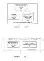
- FIG. 1is a diagram of a system 100 for the insertion and detection of microthread data in transmitted data in accordance with an exemplary embodiment of the present invention.
- System 100performs real-time, automated insertion of microthread data within lossy or lossless carrier data and verifies the reception of the microthread data in the carrier data, so as to allow authentication of transactions and activation of processes dependent on verified receipt of the carrier data.
- System 100includes content system 102 , which can be implemented in hardware, software, or a suitable combination of hardware and software, and which can be one or more software systems operating on a general purpose server platform.
- a software systemcan include one or more objects, agents, threads, subroutines, separate software applications, two or more lines of code or other suitable software structures operating in two or more separate software applications, on two or more different processors, or other suitable software architectures.
- a software systemcan include one or more lines of code or other suitable software structures operating in a general purpose software application, such as an operating system, and one or more lines of code or other suitable software structures operating in a specific purpose software application.
- a software systemcan be one or more lines of hypertext markup language (HTML), extensible markup language (XML), a web browser plug-in, or other suitable code that operates in conjunction with a web browser application.
- HTMLhypertext markup language
- XMLextensible markup language
- web browser plug-inor other suitable code that operates in conjunction with a web
- Content system 102is coupled to microthread insertion system 104 , data transmit system 106 , data receive system 108 , microthread detection system 110 and content player system 112 via communications medium 122 .
- the term “couple,” and its cognate terms such as “couples” and “coupled,”can include a physical connection (such as through one or more copper conductors), a virtual connection (such as one or more randomly assigned data memory locations of a data memory device), a logical connection (such as through one or more logical devices of a semiconducting circuit), a wireless connection, a hypertext transfer protocol (HTTP) connection, other suitable connections, or a suitable combination of such connections.
- systems and componentscan be coupled to other systems and components through intervening systems and components, such as through an operating system of a general purpose server platform.
- Communications medium 122can be the Internet, a local area network, a wide area network, the public switched telephone network, a wireless network, fiber-optic network, other suitable communications media, or a suitable combination of such communications media.
- content system 102can provide digital carrier data to microthread insertion system 104 .
- the digital carrier datacan be lossy data (such as sampled audio or video data), lossless data (such as TCP/IP format data), or other suitable data.
- Lossless datacan include relevant data sequences describing routing information and control information associated with data delivery, such as an Internet protocol (IP) frame header, a transmission control protocol (TCP) header, user datagram protocol (UDP) header, or other suitable protocol headers.
- IPInternet protocol
- TCPtransmission control protocol
- UDPuser datagram protocol
- the microthread datacan be provided to content system 102 , such as prior to or after the provision of the carrier data.
- Microthread insertion system 104includes lossy insertion system 114 and lossless insertion system 116 , each of which can be implemented in hardware, software, or a suitable combination of hardware and software, and which can be one or more software systems operating on a general purpose server platform.
- microthread insertion system 104receives the carrier data, microthread data, and other suitable data from content system 102 and generates a composite data sequence.
- the composite data sequencecan be comprised of the carrier data, one or more instances of the microthread data, one or more flag data sequences, and other suitable data.
- Microthread insertion system 104then provides the composite data sequence to data transmit system 106 .
- Lossy insertion system 114receives lossy carrier data and microthread data, and inserts the microthread data into the lossy carrier data in real-time.
- lossy insertion system 114encrypts the microthread data prior to insertion, such as by using random key, a pseudorandom key, or by other suitable processes.
- the microthread datacan include data used to verify receipt of the carrier data, date and time stamp data, quality of transmission data (such as data that is used to determine whether the transmission quality meets minimum predetermined criteria), advertiser identification data, broadcaster identification data, transmitter identification data, or other suitable data.
- Lossy insertion system 114then generates the composite data sequence that includes the lossy carrier data and the microthread data.
- lossy insertion system 114analyzes the carrier data to identify areas having a predetermined level of data value fluctuation, such as areas in which the standard deviation exceeds a predetermined value, areas in which the absolute magnitude of the change in two or more successive data entries exceeds a predetermined value, or other suitable areas.
- the microthread datacan then be encoded into the carrier data following that location, so as to utilize a repeatable measurement within the carrier signal as a flag.
- insertion of the microthread data in an area in which data signal valuation fluctuations exceed a predetermined leveldecreases the likelihood that any variation in the carrier signal will be detected, such as by the human ear for audio data, by the human eye for video data, or by other suitable procedures.
- Lossy insertion system 114can then further encrypt the composite data sequence using a random key, pseudorandom key, the key used to encrypt the microthread data, or other suitable procedures. Lossy insertion system 114 can then provide any data required to decrypt the microthread (such as a pseudorandom key), the composite data sequence, and other suitable data to data transmit system 106 .
- Lossless insertion system 116receives lossless data to serve as the carrier data.
- Lossless insertion system 116can receive the microthread data from content system 102 , can generate the microthread data, or can receive the microthread data in other suitable manners.
- Lossless insertion system 116encrypts the microthread data, such as by using a random or pseudorandom key or other suitable procedure, and generates the composite data sequence that includes the carrier data and the microthread data.
- lossless insertion system 116inserts the microthread data into the padding data sequence of the areas describing routing information and control information associated with data delivery, such as an IP frame header, a TCP header, a UDP header, or other suitable protocol headers.
- the microthread datacan include data that defines the next location of the microthread data in the data packet stream, so as to increase the difficulty of detecting the microthread data.
- Lossless insertion system 116can then provide any data required to decrypt the microthread data (such as a pseudorandom key), the composite data sequence, and other suitable data to data transmit system 106 .
- Data transmit system 106can be implemented in hardware, software, or a suitable combination of hardware and software, and can be a radio frequency transmitter station in the case of lossy data, or one or more software systems operating on a general purpose processing platform in the case of lossless data.
- data transmit system 106can be an account, a folder, a database or other suitable system on a server of a radio or television broadcast station, a broadcasting authority, a transmitter, or other suitable organization.
- Data transmit system 106transmits the composite data sequence, decryption data (such as a pseudorandom key), and other suitable data to data receive system 108 over communications medium 122 .
- data transmit system 106can transmit radio advertisement data to a receiver.
- the radio advertisement datacan include microthread data that contains broadcast date and time stamp data, copyright data, station identification data, quality of transmission data, or other suitable data.
- data transmit system 106can transmit decryption data such as a pseudorandom key separate from the composite data sequence.
- Data receive system 108can be implemented in hardware, software, or a suitable combination of hardware and software, and can be a radio frequency receiver in the case of lossy data, one or more software systems operating on a general purpose processing platform in the case of lossless data, or other suitable systems.
- data receive system 108can be an account, a folder, a database or other suitable system on a server of a radio or television broadcast station, a broadcasting authority, a transmitter, or other suitable organizations.
- data receive system 108can be a transmission receiving authority or organization which receives lossy data from one or more broadcasting stations, data transmission stations, a broadcasting authority, or other suitable organizations.
- Data receive system 108receives the composite data sequence and the decryption data (such as a pseudorandom key) from data transmit system 106 over communications medium 122 , and provides the data to microthread detection system 110 .
- Microthread detection system 110includes lossy detection system 118 and lossless detection system 120 , each of which can be implemented in hardware, software, a suitable combination of hardware and software, and which can be one or more software systems operating on a general purpose processing platform. Microthread detection system 110 extracts the microthread data from the composite data sequence and provides the microthread data to content player system 112 .
- Lossy detection system 118receives the composite data sequence comprised of lossy data, one or more microthreads, and other suitable data, and extracts the microthread data from the composite data sequence. Lossy detection system 118 can also receive decryption data (such as a pseudorandom key) from data receive system 108 , and can decrypt the composite data, the microthread data, and other suitable data. In one exemplary embodiment, lossy detection system 118 decrypts the composite data, extracts the microthread data, and then further decrypts the microthread data.
- decryption datasuch as a pseudorandom key
- Lossless detection system 120receives the composite data sequence comprised of lossless data packets and extracts the microthread data from the padding data sequence of the areas describing routing and control information in the lossless data.
- Lossless detection system 120can also receive decryption data (such as a pseudorandom key) from data receive system 108 , and can decrypt the composite data, the microthread data, and other suitable data.
- decryption datasuch as a pseudorandom key
- lossless detection system 120decrypts the composite data, extracts the microthread data, and then further decrypts the microthread data.
- lossless detection system 120determines the next location for the microthread data in a subsequent data packet based upon the decrypted microthread data.
- Content player system 112can be implemented in hardware, software or a suitable combination of hardware and software, and can be one or more software systems operating on a general purpose processing platform.
- Content player system 112receives the decrypted composite data sequence, the decrypted and extracted microthread data, and other suitable data.
- content player system 112can verify that the received composite data sequence matches log data, has been received at the location to which the data has been transmitted, has been received from an authorized source, or that other verification data is present.
- content player system 112can initiate an action upon receipt of the microthread data.
- system 100performs real-time insertion and detection of microthread data in carrier data.
- System 100allows the insertion of authenticating codes, date and time stamps, tracking codes, control codes, other verification identifiers, and other suitable data into carrier data in a manner that does not effect the quality or use of the carrier data.
- system 100can be used to monitor carrier data and provide proof of performance of broadcast events, verify the transmission source for the enforcement of copyrights or for authentication of confidential transactions, activate processes dependent on the carrier data, or perform other suitable functions.
- system 100can be used to provide an audit trail for power commodity transactions, to facilitate power transmission and distribution monitoring, to facilitate automated meter reading, for distribution system maintenance, and for other suitable purposes in a power generation, transmission, and distribution system.
- microthread tracking code datacan be inserted directly onto the 60 Hz or other power frequency signal using power line carrier technology. These codes can be inserted at each generation point and repeated at each transformer point along the transmission path and load. Metric data defining the transmission path identity and characteristics can also be inserted at each transformer station for monitoring purposes, and metric data can be inserted at the destination load to automate usage metering.
- microthread datacan be used for transaction authentication, document verification or authentication, wire transfer authentication, or other suitable purposes in banking or financial transactions.
- the microthread datacan be provided with lossless banking data or financial data to serve as a transaction identifier, authentication code, verification code, or other suitable code that can be stored with the data record at the financial institution, at the customer site, or at other suitable locations.
- microthread datacan be provided with medical billing or payment transaction data for transaction authentication, with medical record data for transmission or source verification or authentication, with medical image data for transmission or source verification or authentication, or for other suitable medical or insurance purposes.
- the microthreadcan include a unique transaction code, authentication code, verification code, or other suitable reference key to a data record resident at the medical facility, insurance institution, service provider, consumer site, or other suitable locations.
- microthread datacan be provided for mandated activity authentication, justice or human services record verification or authentication, medical image authentication or verification, or for other suitable purposes for justice or human services.
- the microthreadcan include a unique transaction code, authentication code, verification code, or other suitable reference key to a data record resident at the correction/probation facility, state or federal human services facility, service provider, client site, or other suitable locations.
- microthread datacan be provided for proof of purchase, content license, and market intelligence data gathering purposes in data transmitted over the Internet or other suitable media.
- the microthread datacan include a unique transaction code or other suitable reference key to a data record resident at the content provider site that includes the source, content, and purchaser information of each downloaded content item.
- FIG. 2is a diagram of a system 200 for inserting microthread data into lossy data in accordance with an exemplary embodiment of the present invention.
- System 200includes lossy insertion system 114 and key encryption system 202 , carrier length system 204 , camouflage system 206 and camouflaged microthread insertion system 208 , each of which can be implemented in hardware, software, or suitable combination of hardware and software, and which can be one or more software systems operating on a general purposes processing platform.
- Key encryption system 202generates an encrypted version of microthread data using a random key, a pseudorandom key, or other suitable encryption processes, including those that don't explicitly require a key.
- the microthread datacan contain verification of receipt data, advertising data, date and time stamp data, quality of transmission data, broadcaster identification data, or other suitable data.
- key encryption system 202generates a random bit string having a predetermined length, which is used as a pseudorandom key.
- key encryption system 202generates a pseudorandom bit string to act as the pseudorandom key, where the bit string has a predetermined length that is small enough to be unnoticeable to the human eye or ear after the carrier data has been converted to an audio signal, video signal, graphic image, or other suitable data. Key encryption system 202 then encrypts the microthread data using the key or other suitable processes. In one exemplary embodiment, key encryption system 202 can also encrypt the composite data sequence after the microthread data has been inserted into the carrier data. Key encryption system 202 can also provide the encryption data, such as a pseudorandom key, to data transmit system 106 of FIG. 1 .
- Carrier length system 204receives the carrier data from content system 102 of FIG. 1 and determines if the carrier data has sufficient length to be encoded with one or more repetitions of the microthread data. In one exemplary embodiment, if the carrier data is insufficient, the carrier data can be repeated until the carrier data has sufficient length to contain at least one repetition of the microthread data. Carrier length system 204 then provides the carrier data to camouflage system 206 .
- Camouflage system 206receives the encrypted microthread from key encryption system 202 and the carrier data from carrier length system 204 .
- camouflage system 206analyzes the carrier data to locate areas where the variation in the carrier data exceeds a predetermined level.
- camouflage system 206can receive audio data, video data, graphic image data, or other suitable data and can locate areas where the change in value between two sequential n-bit samples exceeds a predetermined amount. Because such changes indicate a section of audio data in which irregular data having a short duration would be less likely to be noticed by the human eye or ear, flag data and microthread data can be inserted after such sections in a manner that can allows for automated insertion and detection.
- camouflage system 206can detect areas within carrier data that are not used to convey audio data, video data, graphic image data, or other suitable payload data.
- Camouflage system 206can also scan an area occurring after a detected insertion point to determine whether the variation in audio signal data after the insertion point is sufficient to allow the microthread data to be inserted without being noticeable to the human ear.
- the standard deviation of subsequent data point variations, the mean of the absolute values in variation, or other suitable statistical datacan be used to determine whether the area following an insertion point is of sufficient length.
- Camouflage system 206can then mark the areas of interest that are of sufficient length to embed the encrypted microthread with a flag data sequence.
- Camouflage system 206also creates the encrypted microthread camouflage and inserts the encrypted and camouflaged microthread into the carrier data.
- camouflage system 206replicates the data sequence following the insertion point for the length of the encrypted microthread and stores the replicated data sequence in memory.
- Camouflage system 206then generates the camouflaged microthread, such as subtracting the encrypted microthread from the replicated data sequence (D 1 ), adding the encrypted microthread from a second instance of the replicated data sequence (D 2 ), or performing other suitable processes.
- Camouflaged microthread insertion system 208receives the camouflaged microthread from camouflage system 206 and generates a composite data sequence.
- the composite data sequencecan be comprised of the camouflage microthread, the carrier data, and other suitable data.
- camouflaged microthread insertion system 208generates the composite data sequence by inserting the camouflaged microthread after an insertion point, such as by inserting D 1 and D 2 into the carrier signal after the insertion point.
- Flag datacan also be provide between the insertion point and D 1 and D 2 , so as to provide verification of the microtiread data insertion point.
- system 200generates a composite data sequence including lossy carrier data and microthread data.
- Target areas for the insertion of the microthread dataare first identified, such as by using a characteristic of the carrier data that indicates an area where minor changes in the data would not be noticed.
- the microthread datais then camouflaged, such as by using the carrier data after the insertion point, so as to minimize the amount of signal variation created by insertion of the microthread data.
- FIG. 3is a diagram of a system 300 for generating a camouflaged microthread for insertion into lossy carrier data in accordance with an exemplary embodiment of the present invention.
- System 300includes camouflage system 206 and camouflage profile system 302 , difference system 304 , and camouflaged microthread assembly system 306 , each of which can be implemented in hardware, software, or a suitable combination of hardware and software, and which can be one or more software systems operating on a general purpose server platform.
- Camouflage profile system 302generates the camouflage pattern for the creation of the camouflaged microthread based on the areas of interest within the carrier data stream, such as areas occurring after an insertion point. Camouflage profile system 302 can store a section of the carrier data that will then be used to camouflage the microthread data or other suitable camouflage data.
- Carrier flagging system 308provides flag data for insertion in the carrier data after an insertion point, such as to provide an indicator of the existence of a camouflaged microthread.
- the flag datacan be a short sequence of data that is used to confirm that a camouflaged microthread has been inserted.
- the flag datacan include data that is used to locate the next insertion point, data that is used to select an arithmetic operation to be performed on the carrier data following the flag data in order to extract the encrypted microthread, or other suitable data.
- Difference system 304receives the camouflage pattern from camouflage profile system 302 and the encrypted microthread and generates difference data.
- the difference datacan include a first set of data in which the encrypted microthread data has been subtracted from the camouflage pattern (D 1 ), and a second set of data in which the encrypted microthread data has been added to the camouflage pattern (D 2 ).
- D 1the camouflage pattern
- D 2the encrypted microthread can be extracted by subtracting D 1 from D 2 and dividing the result by two.
- Other suitable processescan be implemented by difference system 304 .
- Camouflaged microthread assembly system 306receives the difference data from difference system 304 and generates the camouflaged microthread.
- the camouflaged microthreadcan include D 1 and D 2 , in addition to flag data that is used to indicate a mathematical procedure that is to be performed on D 1 and D 2 to yield the encrypted microthread.
- system 300In operation, system 300 generates a camouflaged microthread for subsequent insertion into carrier data.
- System 300allows an encrypted microthread to be camouflaged by using the carrier data, such that the insertion of the microthread data into the carrier data does not result in a noticeable degradation of the signal.
- FIG. 4is a diagram of a system 400 for detecting microthreads within the composite data sequence comprised of lossy data in accordance with an exemplary embodiment of the present invention.
- System 400includes lossy detection system 118 and key decryption system 402 , camouflaged microthread extraction system 404 , and camouflage removal system 406 , each of which can be implemented in hardware, software, or a suitable combination of hardware and software, and which can be one or more software systems operating on a general purpose server platform.
- Key decryption system 402generates a decrypted version of an encrypted data sequence using a random key, a pseudorandom key, or other suitable decryption mechanisms. Key decryption system 402 can receive a key or other decryption data and encrypted composite data, and can then decrypt the encrypted composite data. Key decryption system 402 can further decrypt the encrypted microthread after it has been extracted from the composite data, such as by using the same decryption key, a different decryption key, or other suitable data.
- Camouflaged microthread extraction system 404receives the decrypted composite data from key decryption system 402 and extracts the microthread data from the composite data. Camouflaged microthread extraction system 404 detects the insertion points for the camouflaged microthreads, such as by determining whether the difference between two successive values of data exceeds a predetermined value, determining whether flag data has been inserted, or by other suitable processes.
- Camouflage removal system 406receives the camouflaged microthread from camouflaged microthread extraction system 404 and removes the camouflage from the camouflaged microthread to reveal the encrypted microthread.
- camouflage removal system 406can remove the camouflage by performing a mathematical operation on two or more data sequences that following an insertion point and flag data. The flag data can likewise be used to identify the mathematical operation.
- system 400decrypts composite data and locates encrypted microthread data in the decrypted composite data.
- the encrypted microthread datais then extracted from the decrypted composite data, and is decrypted. In this manner, the source, date and time of transmission, and other suitable data pertaining to the carrier data can be verified, and other suitable processes can be performed.
- FIG. 5is a diagram of a system 500 for inserting microthread data into lossless data in accordance with an exemplary embodiment of the present invention.
- System 500includes lossless insertion system 116 and key encryption system 502 , carrier flagging system 504 and encrypted microthread insertion system 506 , each of which can be implemented in hardware, software, or suitable combination of hardware and software, and which can be one or more software systems operating on a general purposes processing platform.
- Key encryption system 502receives microthread data and generates an encrypted version of microthread data using a random key, pseudorandom key, or other suitable encryption processes.
- key encryption system 502parses the microthread data so as to allow it to be inserted into predetermined locations of a TCP/IP data frame, a UDP data frame, or other suitable data frames. The parsing data can then be stored for use in locating and assembling the microthread data.
- the microthread datamay be inserted into each data frame, every other data frame, every third data frame, into a predetermined or randomly generated sequence of data frames, or in other suitable manners.
- Carrier flagging system 504receives encrypted microthread data, parsing data, and other suitable data from key encryption system 502 and the carrier data, and generates flag data for locating the microthread data and parsing data within the carrier data.
- the flag datacan include the parsing data, such that the flag data identifies the location within one or more carrier data frames where the microthread data can be located, the re-assembly sequence for parsed microthread data, or other suitable data.
- the flag datacan identify the location of the next data frame in which the microthread data has been stored, the sequence of data frames, or other suitable data.
- Encrypted microthread insertion system 506receives the carrier data, the microthread data, flag data, and other suitable data and assembles the composite data.
- the composite datacan then be encrypted using key encryption system 502 , or other suitable processes can be performed.
- system 500inserts encrypted microthread data into lossless data, such as one or more data frames.
- System 500allows the microthread data to be inserted into predetermined or random locations within the data frames, and further allows the microthread data to be parsed or inserted in successive data frames, a data frame sequence, or in other suitable manners.
- System 500provides flag data or other suitable data that allows the location of the inserted microthread data to be determined at the receiving end.
- FIG. 6is a diagram of a system 600 for detecting the microthread data within the composite data sequence comprised of lossless data in accordance with an exemplary embodiment of the present invention.
- System 600includes lossless detection system 120 and microthread extraction system 602 and key decryption system 604 , each of which can be implemented in hardware, software, or a suitable combination of hardware and software, and which can be one or more software systems operating on a general purpose server platform.
- Microthread extraction system 602locates encrypted microthread data in the data frames of composite data and extracts the encrypted microthread data.
- microthread extraction system 602can use flag data, parsing data, or other suitable data at one or more predetermined location in the data frames of composite data to identify the location in the data frame of the encrypted microthread data, the assembly sequence for parsed encrypted microthread data, the sequence of data frames in which encrypted microthread data has been inserted, or other suitable data.
- Key decryption system 604receives the encrypted microthread data from microthread extraction system 602 and decrypts the data.
- key decryption system 604can receive parsing data from flags extracted by microthread extraction system 602 or other suitable data that is used to locate one or more sections of microthread data within a data frame, such as where the microthread data has been parsed and stored in two or more data frames after being encrypted.
- Other suitable decryption processescan be used by key decryption system 604 .
- system 600extracts and decrypts microthread data from one or more data frames of composite data sequence.
- System 600locates and assembles microthread data that has been parsed and stored in two or more locations, determines data frame sequence or other key data for use in extracting the microthread data, and performs other suitable functions for extracting and decrypting microthread data from lossless carrier data.
- FIG. 7is a flowchart of a method 700 for inserting camouflaged microthread data into lossy data in accordance with an exemplary embodiment of the present invention.
- Method 700begins at 702 where microthread data and carrier data are received.
- the carrier datacan be lossy data, such as audio content data, video content data, or other suitable lossy data.
- the carrier datacan be the audio data, the video data, or a suitable combination of the audio data and the video data.
- the microthread datacan include date and time stamp data, copyright data, quality of the transmission data, or other suitable data.
- the microthread datacan be provided with the carrier data, generated locally when the carrier data is received, or generated in other suitable manners.
- the methodthen proceeds to 704 .
- the microthread datais encrypted, such as with a random key, a pseudorandom key, or by other suitable procedures.
- a random or pseudorandom bit string having a predetermined lengthcan be generated to act as the pseudorandom key.
- the methodthen proceeds to 706 where the length data of the microthread data is obtained and stored.
- the methodthen proceeds to 708 .
- the length data of the carrier datais obtained.
- the methodthen proceeds to 710 where it is determined whether the carrier data is of sufficient length to embed at least one instance of the encrypted microthread. In one exemplary embodiment, it can be determined whether the carrier data has a length equal to or greater than a predetermined multiple of the length of the encrypted microthread. If the carrier data is of insufficient length, then the method proceeds to 712 where the carrier data is repeated until the length of the repeated carrier data is sufficient for the encrypted microthread to be inserted. The method then proceeds to 710 . If it is determined at 710 that the carrier data is of sufficient length, then the method proceeds to 714 .
- the carrier datacan be digitally sampled audio data or other suitable digitally encoded analog data.
- An insertion pointcan be determined by locating two successive values of sequential carrier data that have an absolute magnitude difference greater than a predetermined value.
- the areas within the data stream of the carrier data that are not necessary or are unusable during digital to analog conversioncan be recognized. These areas of interest can then be analyzed to determine whether they are of sufficient length to embed the encrypted microthread, whether the amount of variation in the audio data in the area of interest is sufficient to mask the insertion of the camouflaged microthread, or whether other suitable criteria are met.
- the areas of interest of sufficient lengthcan then be marked with a flag data sequence, such as to provide additional verification of the starting point of the insertion of a camouflaged microthread.
- the methodthen proceeds to 716 .
- a camouflage pattern for the creation of the camouflaged microthreadis extracted from the areas of interest within the carrier data.
- the data sequence having the length of the encrypted microthread immediately following the flag data sequence marking the area of interestcan be replicated and stored in memory as a pattern for the creation of the encrypted microthread camouflage. The method then proceeds to 718 .
- the encrypted microthreadis camouflaged.
- the encrypted microthread datacan be subtracted from a first sequence of the camouflage pattern (D 1 ) and added to a second sequence of the camouflage pattern (D 2 ). In this manner, the encrypted microthread can be extracted by subtracting D 1 from D 2 and dividing the result by two.
- Other suitable mathematical operationcan also be used.
- Flag datacan also be generated, such as data that is used to determine the mathematical operation that must be performed to extract the encrypted microthread data. The method then proceeds to 720 .
- the flag data, camouflaged microthread data, and other suitable dataare inserted into the carrier data to form the composite data.
- the methodthen proceeds to 722 where the composite data sequence is encrypted, such as by using a random key, a pseudorandom key, or other suitable processes.
- the pseudorandom key used to encrypt the microthread data at 704can be used to encrypt the composite data sequence.
- the methodthen proceeds to 724 where the composite data sequence is transmitted.
- Decryption datasuch as the pseudorandom key can also be transmitted, can be transmitted independently, can be used at the transmitting end with a copy of what was received (such as for verification of transmission), or other suitable procedures can be performed.
- method 700generates a composite data sequence by identifying target areas for the insertion of microthread data, camouflaging the microthread data and inserting the camouflaged microthread data in one or more locations of the carrier data.
- Method 700permits the verification of the receipt of digital content, activation of processes dependent on the transmitted content or carrier data and other relevant functions.
- FIG. 8is a flowchart of a method 800 for marking areas of interest in lossy carrier data.
- Method 800begins at 802 where the lossy carrier data is received, such as digitally sampled audio data or other suitable data.
- the methodthen proceeds to 804 where one or more areas of interest within the carrier data are identified.
- the insertion point of an area of interestcan include an area where the absolute magnitude of the difference in the magnitude in two successive samples exceeds a predetermined value.
- one or more areas within the data stream of the carrier data that are not necessary or are unusable during digital to analog conversioncan be identified.
- the methodthen proceeds to 806 .
- the length of the area of interestcan be sufficient if it is greater than a predetermined multiple of the length of the encrypted microthread. If the area of interest is not of sufficient length, then the method proceeds to 808 where the next area of interest is selected. The method then proceeds to 806 . If it is determined at 806 that the area of interest is of sufficient length, then the method proceeds to 810 where the area of interest is marked with a flag data sequence. In one exemplary embodiment, if the area of interest is of sufficient length, then a flag data sequence can be inserted immediately prior to the area of interest and after the insertion point. The method then proceeds to 812 .
- the carrier data following the insertion pointis stored in memory as a pattern for the encrypted microthread camouflage.
- the methodthen proceeds to 814 where it is determined whether the area of interest being replicated is the last area of interest identified at 804 . If not, then the method proceeds to 816 where the next area of interest is selected. The method then proceeds to 806 . In this manner, a flag data sequence can be inserted immediately before one or more areas of interest within the carrier data that are found to be of sufficient length to embed the encrypted microthread, and a camouflage pattern can be stored for each of the flagged areas of interest. Alternatively, the location of insertion points and generation of camouflaged microthread data can be performed sequentially or in other suitable manners. If it is determined at 814 that the area of interest is the last area of interest identified at 804 , then the method proceeds to 818 .
- each of the camouflage patternsare received.
- the methodthen proceeds to 820 where a mathematical operation is performed on the camouflage pattern and the encrypted microthread to form the camouflaged microthread.
- the camouflaged microthreadcan be formed by subtracting the encrypted microthread from the camouflage pattern to form a first camouflage sequence (D 1 ), and by adding the encrypted microthread to the camouflage pattern to form a second camouflage sequence (D 2 ).
- the methodthen proceeds to 822 where the camouflaged microthread, flag data, and other suitable data are combined to form the composite data, such as by inserting the flag data after the insertion point, and inserting D 1 then D 2 after the flag data.
- method 800generates a camouflaged microthread for subsequent insertion into carrier data comprised of lossy data.
- Method 800allows the verification of the transmission of lossy data, where the user needs to identify the copyright owner data, the quality of the broadcast data or transmission data, the date and time stamp data, the station identification data, or other suitable data.
- FIG. 9is a flowchart of a method 900 for detecting microthreads within lossy composite data sequence in accordance with an exemplary embodiment of the present invention.
- Method 900begins at 902 where the encrypted composite data sequence and decryption data, such as a pseudorandom key, is received. The method then proceeds to 904 where the composite data sequence is decrypted using the decryption data. The method then proceeds to 906 .
- decryption datasuch as a pseudorandom key
- the camouflaged microthreadis extracted from the composite data sequence.
- the insertion pointscan first be identified, such as be determining areas in which the absolute magnitude in the value of two successive data points exceeds a predetermined value, and then verifying that the flag data sequence is present.
- the camouflaged microthreadscan then be extracted from the composite data.
- a data sequence twice the length of the encrypted microthread following the flag data sequencecan be extracted as the camouflaged microthread, or other suitable processes can be used. The method then proceeds to 908 .
- the camouflage of the camouflaged microthreadis removed to reveal the encrypted microthread.
- the camouflagecan be removed by taking the data sequence immediately following the flag data sequence of twice the length of the encrypted microthread, subtracting the first sequence from the second sequence, and dividing the result by two. Likewise, other suitable processes can be used. The method then proceeds to 910 .
- the encrypted microthreadis decrypted using decryption data, such as a pseudorandom key or other suitable data.
- decryption datasuch as a pseudorandom key or other suitable data.
- the microthread datacan provide identification of the digital content data, identification of the broadcast data or transmission data, time and date stamp data, quality of the broadcast data or transmission data, station identification data, and other suitable data to a database for accounting purposes.
- method 900allows microthread data within a composite data sequence to be detected.
- Method 900allows the verification of the receipt of digital content data, the activation of processes dependent on the digital content or carrier data, and the identification of the digital content data to be performed without manual intervention.
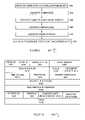
- FIG. 10is a diagram of a data frame 1000 for providing camouflaged microthread data with lossless data in accordance with an exemplary embodiment of the present invention.
- this representationcan be the IP header section of lossless transmitted data.
- Sequence 1002is the first sequence of the data stream. Sequence 1002 contains version data indicating the format of the Internet header. Sequence 1004 contains Internet header length data indicating the length of the Internet header. Sequence 1006 contains type of service data indicating the desired quality of service. Sequence 1008 contains total length data indicating the length of the datagram measured in bytes, including the Internet header and data. Sequence 1010 contains identification data indicating the identifying value assigned by the sender to aid in assembling the fragments of the datagram. Sequence 1012 contains flag data representing control flags. Sequence 1014 contains fragment offset data indicating where the fragment belongs in the datagram. Sequence 1016 contains time to live data indicating the maximum time the datagram is allowed to remain in the Internet system.
- Sequence 1018contains protocol data indicating the next level protocol used in the data portion of the Internet datagram.
- Sequence 1020contains header checksum data indicating a checksum on the header only.
- Sequence 1022contains source IP address data indicating the source IP address.
- Sequence 1024contains destination IP address data indicating the destination IP address.
- Sequence 1026contains IP options data indicating the options implemented by the IP modules.
- Sequence 1028is the padding data sequence of the header. In one exemplary embodiment, this can be the area of interest where the camouflaged microthread 1028 A is inserted. In another exemplary embodiment, the padding data sequence of the header can include locator data 1028 B that identifies a location in the payload data at which to find the microthread data, such that the payload data is used to camouflage the microthread data.
- the padding sequence datacan include locator data that identifies the next data frame in which the microthread data is located, either as data in the padding data sequence, data in the payload data portion of the data frame, a suitable combination of such data, or other suitable data, such as other data sequences in which the microthread data or locator data can be found.
- Sequence 1030is the payload data section.
- data frame 1000allows microthread data to be inserted and camouflaged using the carrier data of the data frame, such as padding data sequences, payload data, other suitable data sequences, or a suitable combination of such data sequences.
- data frame 1000uses the same frame structure as an IP frame header, other suitable standardized or proprietary data frames structures can also or alternatively be used, where suitable.
- FIG. 11is a flowchart of a method 1100 for inserting microthread data into lossless data in accordance with an exemplary embodiment of the present invention.
- Method 1100begins at 1102 where the microthread data and the carrier data are received.
- the carrier datacan be lossless data, such as financial data, transactional data, medical record data, or other suitable lossless data.
- lossless datacan include relevant data sequences describing routing information and control information associated with datagram delivery, such as the IP frame header, TCP header, UDP header, or other suitable protocol headers.
- the microthread datacan be composed of the information relevant to the content signal of the carrier data, a continuous time code comprising date and time stamp data, authentication data, verification of receipt data, or other suitable data.
- the methodthen proceeds to 1104 where the microthread data is encrypted, such as with a random or pseudorandom key or by other suitable processes.
- a random or pseudorandom bit string of any lengthcan be generated to act as the pseudorandom key.
- the methodthen proceeds to 1106 .
- an area of interest within the carrier datais identified.
- an area of interestcan include a padding data sequence of the areas of lossless data describing routing information and control information associated with datagram delivery, such as an IP frame header, a TCP header, a UDP header, or other suitable protocol headers.
- the methodthen proceeds to 1108 where the area of interest is marked with a flag data sequence.
- a flag data sequencecan be inserted immediately prior to the padding data sequence.
- the beginning data sequence of the length of the flag data sequencecan be replaced with the flag data sequence.
- data sequence 1028 of FIG. 10can serve as the flag data sequence.
- marking the area of interest with an explicit flag data sequenceis not required, as the flag data sequence is inherent in the frame structure.
- the flag data sequencecan also be inserted into the payload data, such that the microthread data is included in the payload data.
- the flag data sequencecan also include locator data that identifies the next frame in which the microthread is stored, the location within the payload data in which the microthread data is stored, the location in the data frame (such as in other data sequences of data frame 1000 ) in which the microthread data, flag data, or locator data is stored, or other suitable data. The method then proceeds to 1110 .
- the encrypted microthreadis inserted into the carrier data.
- the resulting data sequenceis called the composite data sequence.
- the composite data sequencecan include the encrypted microthread, the flag data sequence, the lossless data, and other suitable data.
- the encrypted microthreadcan be inserted immediately after the flag data sequence.
- a portion of the data stream of the padding data sequence of the length of the encrypted microthreadcan be replaced with the encrypted microthread.
- the encrypted microthreadcan be inserted immediately after data sequence 1226 of FIG. 12 .
- the methodthen proceeds to 1112 where the composite data sequence is transmitted.
- Decryption datasuch as the pseudorandom key can also be transmitted, can be transmitted independently, can be used at the transmitting end with a copy of what was received (such as for verification of transmission), or other suitable procedures can be performed.
- method 1100inserts an encrypted microthread in the padding data sequence of the areas of lossless data describing routing information and control information.
- Method 1100allows the insertion of microthreads containing verification of receipt data, date and time stamp data, authentication data, tracking data, or other suitable data.
- Method 1100permits the verification of the receipt of lossless data, the activation of processes dependent on the transmitted content or carrier, and the authentication of sensitive and confidential transactions.
- FIG. 12is a flowchart of a method 1200 for detecting microthread data within a composite data sequence comprised of lossless data in accordance with an exemplary embodiment of the present invention.
- Method 1200begins at 1202 where the composite data sequence and decryption data, such as a pseudorandom key or other suitable data, is received. The method then proceeds to 1204 .
- the flag data sequence within the composite data sequenceis identified.
- the location of the flag data sequencecan be identified using a copy of the flag data sequence, such as by transmitting the flag data sequence with the composite data sequence, prior to the composite data sequence, or in other suitable manners.
- the pseudorandom keycan contain the flag data sequence. The method then proceeds to 1206 .
- the encrypted microthreadis extracted from the composite data sequence.
- the encrypted microthreadcan be detected using the location of the flag data sequence or in other suitable manners. The method then proceeds to 1208 .
- the encrypted microthreadis decrypted using the decryption data.
- the methodthen proceeds to 1210 where any processes dependent on the carrier data are activated.
- the processes dependent on the carrier datacan include verification of the receipt of lossless data and authentication of the lossless data.
- method 1200detects and generates a copy of the microthread data within the composite data sequence comprised of lossless data, the encrypted microthread, the flag data sequence, and other suitable data.
- Method 1200permits the automated verification of the receipt of lossless data, the activation of processes dependent on the lossless data, and the authentication of sensitive and confidential transactions.
Landscapes
- Engineering & Computer Science (AREA)
- Computer Security & Cryptography (AREA)
- Computer Hardware Design (AREA)
- Computing Systems (AREA)
- General Engineering & Computer Science (AREA)
- Computer Networks & Wireless Communication (AREA)
- Signal Processing (AREA)
- Storage Device Security (AREA)
Abstract
Description
Claims (20)
Priority Applications (2)
| Application Number | Priority Date | Filing Date | Title |
|---|---|---|---|
| US09/915,174US7124442B2 (en) | 2001-07-25 | 2001-07-25 | System and method for insertion and retrieval of microthreads in transmitted data |
| PCT/US2002/023646WO2003010918A1 (en) | 2001-07-25 | 2002-07-25 | System and method for insertion and retrieval of microthreads in transmitted data |
Applications Claiming Priority (1)
| Application Number | Priority Date | Filing Date | Title |
|---|---|---|---|
| US09/915,174US7124442B2 (en) | 2001-07-25 | 2001-07-25 | System and method for insertion and retrieval of microthreads in transmitted data |
Publications (2)
| Publication Number | Publication Date |
|---|---|
| US20030021414A1 US20030021414A1 (en) | 2003-01-30 |
| US7124442B2true US7124442B2 (en) | 2006-10-17 |
Family
ID=25435356
Family Applications (1)
| Application Number | Title | Priority Date | Filing Date |
|---|---|---|---|
| US09/915,174Expired - Fee RelatedUS7124442B2 (en) | 2001-07-25 | 2001-07-25 | System and method for insertion and retrieval of microthreads in transmitted data |
Country Status (2)
| Country | Link |
|---|---|
| US (1) | US7124442B2 (en) |
| WO (1) | WO2003010918A1 (en) |
Cited By (33)
| Publication number | Priority date | Publication date | Assignee | Title |
|---|---|---|---|---|
| US20070130590A1 (en)* | 2005-09-20 | 2007-06-07 | Nash-Putnam Jon S | Method, system and program product for broadcast operations utilizing internet protocol and digital artifacts |
| US20070220544A1 (en)* | 2005-09-20 | 2007-09-20 | Jon Nash-Putnam | Method, system and program product for broadcast advertising and other broadcast content performance verification utilizing digital artifacts |
| US20070256089A1 (en)* | 2005-09-20 | 2007-11-01 | Putnam Jon S | Method, system and program product for broadcast error protection of content elements utilizing digital artifacts |
| US20080084949A1 (en)* | 2005-09-20 | 2008-04-10 | Putnam Jon S | Method, system and program product for the insertion and retrieval of identifying artifacts in transmitted lossy and lossless data |
| US20080205400A1 (en)* | 2007-02-22 | 2008-08-28 | Cisco Technology Inc. | Low deviation field modulation for transfer of information |
| US20080224902A1 (en)* | 2007-03-12 | 2008-09-18 | Allen Samuels | Systems and methods of using application and protocol specific parsing for compression |
| US20080224903A1 (en)* | 2007-03-12 | 2008-09-18 | Allen Samuels | Systems and methods for sharing compression histories between multiple devices |
| US20080224906A1 (en)* | 2007-03-12 | 2008-09-18 | Robert Plamondon | Systems and methods for identifying long matches of data in a compression history |
| US20080228850A1 (en)* | 2007-03-12 | 2008-09-18 | Allen Samuels | Systems and methods of clustered sharing of compression histories |
| US20080242946A1 (en)* | 2007-03-30 | 2008-10-02 | Sony Corporation | Method and apparatus for transporting images |
| US20090083901A1 (en)* | 2007-10-01 | 2009-04-02 | Pardillo Joseph M | Protective pad assembly magnetically attachable to garment |
| US7606902B2 (en) | 2004-07-23 | 2009-10-20 | Citrix Systems, Inc. | Method and systems for routing packets from an endpoint to a gateway |
| US7609721B2 (en) | 2004-07-23 | 2009-10-27 | Citrix Systems, Inc. | Systems and methods for adjusting the maximum transmission unit for encrypted communications |
| US7657657B2 (en) | 2004-08-13 | 2010-02-02 | Citrix Systems, Inc. | Method for maintaining transaction integrity across multiple remote access servers |
| US7757074B2 (en) | 2004-06-30 | 2010-07-13 | Citrix Application Networking, Llc | System and method for establishing a virtual private network |
| US7827237B2 (en) | 2007-03-12 | 2010-11-02 | Citrix Systems, Inc. | Systems and methods for identifying long matches of data in a compression history |
| US7849270B2 (en) | 2005-01-24 | 2010-12-07 | Citrix Systems, Inc. | System and method for performing entity tag and cache control of a dynamically generated object not identified as cacheable in a network |
| US7865585B2 (en) | 2007-03-12 | 2011-01-04 | Citrix Systems, Inc. | Systems and methods for providing dynamic ad hoc proxy-cache hierarchies |
| US7921184B2 (en) | 2005-12-30 | 2011-04-05 | Citrix Systems, Inc. | System and method for performing flash crowd caching of dynamically generated objects in a data communication network |
| US7978716B2 (en) | 2003-11-24 | 2011-07-12 | Citrix Systems, Inc. | Systems and methods for providing a VPN solution |
| US8065166B2 (en) | 2007-10-30 | 2011-11-22 | Onemednet Corporation | Methods, systems, and devices for managing medical images and records |
| US8255570B2 (en) | 2007-03-12 | 2012-08-28 | Citrix Systems, Inc. | Systems and methods of compression history expiration and synchronization |
| US8255456B2 (en) | 2005-12-30 | 2012-08-28 | Citrix Systems, Inc. | System and method for performing flash caching of dynamically generated objects in a data communication network |
| US8301839B2 (en) | 2005-12-30 | 2012-10-30 | Citrix Systems, Inc. | System and method for performing granular invalidation of cached dynamically generated objects in a data communication network |
| US8495305B2 (en) | 2004-06-30 | 2013-07-23 | Citrix Systems, Inc. | Method and device for performing caching of dynamically generated objects in a data communication network |
| US8549149B2 (en) | 2004-12-30 | 2013-10-01 | Citrix Systems, Inc. | Systems and methods for providing client-side accelerated access to remote applications via TCP multiplexing |
| US8700695B2 (en) | 2004-12-30 | 2014-04-15 | Citrix Systems, Inc. | Systems and methods for providing client-side accelerated access to remote applications via TCP pooling |
| US8706877B2 (en) | 2004-12-30 | 2014-04-22 | Citrix Systems, Inc. | Systems and methods for providing client-side dynamic redirection to bypass an intermediary |
| US8739274B2 (en) | 2004-06-30 | 2014-05-27 | Citrix Systems, Inc. | Method and device for performing integrated caching in a data communication network |
| US8856777B2 (en) | 2004-12-30 | 2014-10-07 | Citrix Systems, Inc. | Systems and methods for automatic installation and execution of a client-side acceleration program |
| US8954595B2 (en) | 2004-12-30 | 2015-02-10 | Citrix Systems, Inc. | Systems and methods for providing client-side accelerated access to remote applications via TCP buffering |
| US9171344B2 (en) | 2007-10-30 | 2015-10-27 | Onemednet Corporation | Methods, systems, and devices for managing medical images and records |
| US9760677B2 (en) | 2009-04-29 | 2017-09-12 | Onemednet Corporation | Methods, systems, and devices for managing medical images and records |
Families Citing this family (5)
| Publication number | Priority date | Publication date | Assignee | Title |
|---|---|---|---|---|
| AU2002213430A1 (en)* | 2000-09-28 | 2002-04-08 | Ipdev Co. | Method for simplified one-touch ordering of goods and services from a wired or wireless phone or terminal |
| US7400729B2 (en)* | 2001-12-28 | 2008-07-15 | Intel Corporation | Secure delivery of encrypted digital content |
| US7307666B2 (en)* | 2003-01-30 | 2007-12-11 | Her Majesty The Queen In Right Of Canada As Represented By The Minister Of Industry Through The Communications Research Centre Canada | Transmitter identification system |
| CA2453902A1 (en)* | 2003-01-30 | 2004-07-30 | Brian A. Harron | Gimballed reflector mounting platform |
| US20180040083A1 (en)* | 2008-06-11 | 2018-02-08 | James D. Bennett | Creative Work Registry |
Citations (25)
| Publication number | Priority date | Publication date | Assignee | Title |
|---|---|---|---|---|
| US5613004A (en) | 1995-06-07 | 1997-03-18 | The Dice Company | Steganographic method and device |
| US5636292A (en) | 1995-05-08 | 1997-06-03 | Digimarc Corporation | Steganography methods employing embedded calibration data |
| EP0859503A2 (en) | 1997-02-12 | 1998-08-19 | Nec Corporation | Electronic watermark system |
| US5850481A (en) | 1993-11-18 | 1998-12-15 | Digimarc Corporation | Steganographic system |
| EP0899688A2 (en) | 1997-08-29 | 1999-03-03 | Fujitsu Limited | Device for generating, detecting, recording, and reproducing a watermarked moving image |
| US5889868A (en) | 1996-07-02 | 1999-03-30 | The Dice Company | Optimization methods for the insertion, protection, and detection of digital watermarks in digitized data |
| US5905800A (en) | 1996-01-17 | 1999-05-18 | The Dice Company | Method and system for digital watermarking |
| US6026193A (en) | 1993-11-18 | 2000-02-15 | Digimarc Corporation | Video steganography |
| US6047374A (en) | 1994-12-14 | 2000-04-04 | Sony Corporation | Method and apparatus for embedding authentication information within digital data |
| WO2000025203A1 (en) | 1998-10-28 | 2000-05-04 | Datamark Technologies Pte Ltd. | Methods of digital steganography for multimedia data |
| EP1031944A1 (en) | 1999-02-22 | 2000-08-30 | Institut Eurecom G.I.E. | Process for marking a multimedia document, such as an image, by generating a mark |
| WO2000054453A1 (en) | 1999-03-10 | 2000-09-14 | Digimarc Corporation | Signal processing methods, devices, and applications for digital rights management |
| EP1063833A2 (en) | 1999-06-23 | 2000-12-27 | Hitachi, Ltd. | System for filtering data utilizing electronic watermark |
| EP1075108A1 (en) | 1999-07-23 | 2001-02-07 | BRITISH TELECOMMUNICATIONS public limited company | Cryptographic data distribution |
| EP1079627A1 (en) | 1999-08-27 | 2001-02-28 | Canon Kabushiki Kaisha | Copyright protection in MPEG-4 using digital watermarking |
| US6205249B1 (en) | 1998-04-02 | 2001-03-20 | Scott A. Moskowitz | Multiple transform utilization and applications for secure digital watermarking |
| WO2001022652A2 (en) | 1999-09-21 | 2001-03-29 | Discovery Communications, Inc. | Electronic book security and copyright protection system |
| US6216228B1 (en) | 1997-04-23 | 2001-04-10 | International Business Machines Corporation | Controlling video or image presentation according to encoded content classification information within the video or image data |
| WO2001045410A2 (en) | 1999-12-15 | 2001-06-21 | Sun Microsystems, Inc. | A method and apparatus for watermarking digital content |
| WO2001045316A1 (en) | 1999-12-16 | 2001-06-21 | Markany Inc. | Method and apparatus for embedding text watermark |
| US6285774B1 (en)* | 1998-06-08 | 2001-09-04 | Digital Video Express, L.P. | System and methodology for tracing to a source of unauthorized copying of prerecorded proprietary material, such as movies |
| US20020076043A1 (en) | 2000-10-11 | 2002-06-20 | Van Der Vleuten Renatus Josephus | Coding |
| US6625295B1 (en)* | 1996-09-13 | 2003-09-23 | Purdue Research Foundation | Authentication of signals using watermarks |
| US6668246B1 (en)* | 1999-03-24 | 2003-12-23 | Intel Corporation | Multimedia data delivery and playback system with multi-level content and privacy protection |
| US6721437B1 (en)* | 1999-02-05 | 2004-04-13 | Sony Corporation | Data processing apparatus, coding apparatus, data processing method and coding method |
- 2001
- 2001-07-25USUS09/915,174patent/US7124442B2/ennot_activeExpired - Fee Related
- 2002
- 2002-07-25WOPCT/US2002/023646patent/WO2003010918A1/ennot_activeApplication Discontinuation
Patent Citations (30)
| Publication number | Priority date | Publication date | Assignee | Title |
|---|---|---|---|---|
| US5850481C1 (en) | 1993-11-18 | 2002-07-16 | Digimarc Corp | Steganographic system |
| US5850481A (en) | 1993-11-18 | 1998-12-15 | Digimarc Corporation | Steganographic system |
| US6026193A (en) | 1993-11-18 | 2000-02-15 | Digimarc Corporation | Video steganography |
| US6101604A (en) | 1994-12-14 | 2000-08-08 | Sony Corporation | Method and apparatus for embedding authentication information within digital data |
| US6163842A (en) | 1994-12-14 | 2000-12-19 | Sony Corporation | Method and apparatus for embedding authentication information within digital data |
| US6047374A (en) | 1994-12-14 | 2000-04-04 | Sony Corporation | Method and apparatus for embedding authentication information within digital data |
| US5636292A (en) | 1995-05-08 | 1997-06-03 | Digimarc Corporation | Steganography methods employing embedded calibration data |
| US5636292C1 (en) | 1995-05-08 | 2002-06-18 | Digimarc Corp | Steganography methods employing embedded calibration data |
| US5687236A (en) | 1995-06-07 | 1997-11-11 | The Dice Company | Steganographic method and device |
| US5613004A (en) | 1995-06-07 | 1997-03-18 | The Dice Company | Steganographic method and device |
| US5905800A (en) | 1996-01-17 | 1999-05-18 | The Dice Company | Method and system for digital watermarking |
| US5889868A (en) | 1996-07-02 | 1999-03-30 | The Dice Company | Optimization methods for the insertion, protection, and detection of digital watermarks in digitized data |
| US6625295B1 (en)* | 1996-09-13 | 2003-09-23 | Purdue Research Foundation | Authentication of signals using watermarks |
| EP0859503A2 (en) | 1997-02-12 | 1998-08-19 | Nec Corporation | Electronic watermark system |
| US6216228B1 (en) | 1997-04-23 | 2001-04-10 | International Business Machines Corporation | Controlling video or image presentation according to encoded content classification information within the video or image data |
| EP0899688A2 (en) | 1997-08-29 | 1999-03-03 | Fujitsu Limited | Device for generating, detecting, recording, and reproducing a watermarked moving image |
| US6205249B1 (en) | 1998-04-02 | 2001-03-20 | Scott A. Moskowitz | Multiple transform utilization and applications for secure digital watermarking |
| US6285774B1 (en)* | 1998-06-08 | 2001-09-04 | Digital Video Express, L.P. | System and methodology for tracing to a source of unauthorized copying of prerecorded proprietary material, such as movies |
| WO2000025203A1 (en) | 1998-10-28 | 2000-05-04 | Datamark Technologies Pte Ltd. | Methods of digital steganography for multimedia data |
| US6721437B1 (en)* | 1999-02-05 | 2004-04-13 | Sony Corporation | Data processing apparatus, coding apparatus, data processing method and coding method |
| EP1031944A1 (en) | 1999-02-22 | 2000-08-30 | Institut Eurecom G.I.E. | Process for marking a multimedia document, such as an image, by generating a mark |
| WO2000054453A1 (en) | 1999-03-10 | 2000-09-14 | Digimarc Corporation | Signal processing methods, devices, and applications for digital rights management |
| US6668246B1 (en)* | 1999-03-24 | 2003-12-23 | Intel Corporation | Multimedia data delivery and playback system with multi-level content and privacy protection |
| EP1063833A2 (en) | 1999-06-23 | 2000-12-27 | Hitachi, Ltd. | System for filtering data utilizing electronic watermark |
| EP1075108A1 (en) | 1999-07-23 | 2001-02-07 | BRITISH TELECOMMUNICATIONS public limited company | Cryptographic data distribution |
| EP1079627A1 (en) | 1999-08-27 | 2001-02-28 | Canon Kabushiki Kaisha | Copyright protection in MPEG-4 using digital watermarking |
| WO2001022652A2 (en) | 1999-09-21 | 2001-03-29 | Discovery Communications, Inc. | Electronic book security and copyright protection system |
| WO2001045410A2 (en) | 1999-12-15 | 2001-06-21 | Sun Microsystems, Inc. | A method and apparatus for watermarking digital content |
| WO2001045316A1 (en) | 1999-12-16 | 2001-06-21 | Markany Inc. | Method and apparatus for embedding text watermark |
| US20020076043A1 (en) | 2000-10-11 | 2002-06-20 | Van Der Vleuten Renatus Josephus | Coding |
Non-Patent Citations (2)
| Title |
|---|
| Memon, N., et al, 'A Buyer-Seller Watermarking Protocol', IEEE Signal Processing Society 1998 Workshop on Multimedia Signal Processing,Dec. 7-9, 1998, Los Angeles, California, USA Electronic Proceedings (C) 1998 IEEE , entire document http://www.tsi.enst.fr/~maitre/tatouage/mmsp98/355/index.htm.* |
| Search Report for PCT/US02/23646 Dated Jan. 10, 2003 in related PCT filing of pending U.S. Appl. No. 09/915,174. |
Cited By (79)
| Publication number | Priority date | Publication date | Assignee | Title |
|---|---|---|---|---|
| US8559449B2 (en) | 2003-11-11 | 2013-10-15 | Citrix Systems, Inc. | Systems and methods for providing a VPN solution |
| US7978716B2 (en) | 2003-11-24 | 2011-07-12 | Citrix Systems, Inc. | Systems and methods for providing a VPN solution |
| US7757074B2 (en) | 2004-06-30 | 2010-07-13 | Citrix Application Networking, Llc | System and method for establishing a virtual private network |
| US8261057B2 (en) | 2004-06-30 | 2012-09-04 | Citrix Systems, Inc. | System and method for establishing a virtual private network |
| US8495305B2 (en) | 2004-06-30 | 2013-07-23 | Citrix Systems, Inc. | Method and device for performing caching of dynamically generated objects in a data communication network |
| US8739274B2 (en) | 2004-06-30 | 2014-05-27 | Citrix Systems, Inc. | Method and device for performing integrated caching in a data communication network |
| US8726006B2 (en) | 2004-06-30 | 2014-05-13 | Citrix Systems, Inc. | System and method for establishing a virtual private network |
| US8351333B2 (en) | 2004-07-23 | 2013-01-08 | Citrix Systems, Inc. | Systems and methods for communicating a lossy protocol via a lossless protocol using false acknowledgements |
| US8019868B2 (en) | 2004-07-23 | 2011-09-13 | Citrix Systems, Inc. | Method and systems for routing packets from an endpoint to a gateway |
| US8892778B2 (en) | 2004-07-23 | 2014-11-18 | Citrix Systems, Inc. | Method and systems for securing remote access to private networks |
| US7978714B2 (en) | 2004-07-23 | 2011-07-12 | Citrix Systems, Inc. | Methods and systems for securing access to private networks using encryption and authentication technology built in to peripheral devices |
| US8291119B2 (en) | 2004-07-23 | 2012-10-16 | Citrix Systems, Inc. | Method and systems for securing remote access to private networks |
| US8897299B2 (en) | 2004-07-23 | 2014-11-25 | Citrix Systems, Inc. | Method and systems for routing packets from a gateway to an endpoint |
| US8046830B2 (en) | 2004-07-23 | 2011-10-25 | Citrix Systems, Inc. | Systems and methods for network disruption shielding techniques |
| US8634420B2 (en) | 2004-07-23 | 2014-01-21 | Citrix Systems, Inc. | Systems and methods for communicating a lossy protocol via a lossless protocol |
| US7606902B2 (en) | 2004-07-23 | 2009-10-20 | Citrix Systems, Inc. | Method and systems for routing packets from an endpoint to a gateway |
| US7609721B2 (en) | 2004-07-23 | 2009-10-27 | Citrix Systems, Inc. | Systems and methods for adjusting the maximum transmission unit for encrypted communications |
| US8014421B2 (en) | 2004-07-23 | 2011-09-06 | Citrix Systems, Inc. | Systems and methods for adjusting the maximum transmission unit by an intermediary device |
| US7808906B2 (en)* | 2004-07-23 | 2010-10-05 | Citrix Systems, Inc. | Systems and methods for communicating a lossy protocol via a lossless protocol using false acknowledgements |
| US8914522B2 (en) | 2004-07-23 | 2014-12-16 | Citrix Systems, Inc. | Systems and methods for facilitating a peer to peer route via a gateway |
| US7724657B2 (en) | 2004-07-23 | 2010-05-25 | Citrix Systems, Inc. | Systems and methods for communicating a lossy protocol via a lossless protocol |
| US9219579B2 (en) | 2004-07-23 | 2015-12-22 | Citrix Systems, Inc. | Systems and methods for client-side application-aware prioritization of network communications |
| US7657657B2 (en) | 2004-08-13 | 2010-02-02 | Citrix Systems, Inc. | Method for maintaining transaction integrity across multiple remote access servers |
| US8549149B2 (en) | 2004-12-30 | 2013-10-01 | Citrix Systems, Inc. | Systems and methods for providing client-side accelerated access to remote applications via TCP multiplexing |
| US8856777B2 (en) | 2004-12-30 | 2014-10-07 | Citrix Systems, Inc. | Systems and methods for automatic installation and execution of a client-side acceleration program |
| US8700695B2 (en) | 2004-12-30 | 2014-04-15 | Citrix Systems, Inc. | Systems and methods for providing client-side accelerated access to remote applications via TCP pooling |
| US8706877B2 (en) | 2004-12-30 | 2014-04-22 | Citrix Systems, Inc. | Systems and methods for providing client-side dynamic redirection to bypass an intermediary |
| US8954595B2 (en) | 2004-12-30 | 2015-02-10 | Citrix Systems, Inc. | Systems and methods for providing client-side accelerated access to remote applications via TCP buffering |
| US7849269B2 (en) | 2005-01-24 | 2010-12-07 | Citrix Systems, Inc. | System and method for performing entity tag and cache control of a dynamically generated object not identified as cacheable in a network |
| US7849270B2 (en) | 2005-01-24 | 2010-12-07 | Citrix Systems, Inc. | System and method for performing entity tag and cache control of a dynamically generated object not identified as cacheable in a network |
| US8788581B2 (en) | 2005-01-24 | 2014-07-22 | Citrix Systems, Inc. | Method and device for performing caching of dynamically generated objects in a data communication network |
| US8848710B2 (en) | 2005-01-24 | 2014-09-30 | Citrix Systems, Inc. | System and method for performing flash caching of dynamically generated objects in a data communication network |
| US20080084949A1 (en)* | 2005-09-20 | 2008-04-10 | Putnam Jon S | Method, system and program product for the insertion and retrieval of identifying artifacts in transmitted lossy and lossless data |
| US8966517B2 (en) | 2005-09-20 | 2015-02-24 | Forefront Assets Limited Liability Company | Method, system and program product for broadcast operations utilizing internet protocol and digital artifacts |
| US20070130590A1 (en)* | 2005-09-20 | 2007-06-07 | Nash-Putnam Jon S | Method, system and program product for broadcast operations utilizing internet protocol and digital artifacts |
| US8566857B2 (en) | 2005-09-20 | 2013-10-22 | Forefront Assets Limited Liability Company | Method, system and program product for broadcast advertising and other broadcast content performance verification utilizing digital artifacts |
| US20070256089A1 (en)* | 2005-09-20 | 2007-11-01 | Putnam Jon S | Method, system and program product for broadcast error protection of content elements utilizing digital artifacts |
| US7668205B2 (en) | 2005-09-20 | 2010-02-23 | Celo Data, Inc. | Method, system and program product for the insertion and retrieval of identifying artifacts in transmitted lossy and lossless data |
| US8566858B2 (en) | 2005-09-20 | 2013-10-22 | Forefront Assets Limited Liability Company | Method, system and program product for broadcast error protection of content elements utilizing digital artifacts |
| USRE47229E1 (en) | 2005-09-20 | 2019-02-05 | Gula Consulting Limited Liability Company | Method, system and program product for broadcast operations utilizing internet protocol and digital artifacts |
| US20070220544A1 (en)* | 2005-09-20 | 2007-09-20 | Jon Nash-Putnam | Method, system and program product for broadcast advertising and other broadcast content performance verification utilizing digital artifacts |
| US7921184B2 (en) | 2005-12-30 | 2011-04-05 | Citrix Systems, Inc. | System and method for performing flash crowd caching of dynamically generated objects in a data communication network |
| US8255456B2 (en) | 2005-12-30 | 2012-08-28 | Citrix Systems, Inc. | System and method for performing flash caching of dynamically generated objects in a data communication network |
| US8499057B2 (en) | 2005-12-30 | 2013-07-30 | Citrix Systems, Inc | System and method for performing flash crowd caching of dynamically generated objects in a data communication network |
| US8301839B2 (en) | 2005-12-30 | 2012-10-30 | Citrix Systems, Inc. | System and method for performing granular invalidation of cached dynamically generated objects in a data communication network |
| US7602817B2 (en)* | 2007-02-22 | 2009-10-13 | Cisco Technology, Inc. | Low deviation field modulation for transfer of information |
| US20080205400A1 (en)* | 2007-02-22 | 2008-08-28 | Cisco Technology Inc. | Low deviation field modulation for transfer of information |
| US20080224903A1 (en)* | 2007-03-12 | 2008-09-18 | Allen Samuels | Systems and methods for sharing compression histories between multiple devices |
| US7916047B2 (en) | 2007-03-12 | 2011-03-29 | Citrix Systems, Inc. | Systems and methods of clustered sharing of compression histories |
| US7460038B2 (en) | 2007-03-12 | 2008-12-02 | Citrix Systems, Inc. | Systems and methods of clustered sharing of compression histories |
| US8255570B2 (en) | 2007-03-12 | 2012-08-28 | Citrix Systems, Inc. | Systems and methods of compression history expiration and synchronization |
| US7453379B2 (en) | 2007-03-12 | 2008-11-18 | Citrix Systems, Inc. | Systems and methods for identifying long matches of data in a compression history |
| US8352605B2 (en) | 2007-03-12 | 2013-01-08 | Citrix Systems, Inc. | Systems and methods for providing dynamic ad hoc proxy-cache hierarchies |
| US7865585B2 (en) | 2007-03-12 | 2011-01-04 | Citrix Systems, Inc. | Systems and methods for providing dynamic ad hoc proxy-cache hierarchies |
| US8063799B2 (en)* | 2007-03-12 | 2011-11-22 | Citrix Systems, Inc. | Systems and methods for sharing compression histories between multiple devices |
| US7872597B2 (en)* | 2007-03-12 | 2011-01-18 | Citrix Systems, Inc. | Systems and methods of using application and protocol specific parsing for compression |
| US8832300B2 (en) | 2007-03-12 | 2014-09-09 | Citrix Systems, Inc. | Systems and methods for identifying long matches of data in a compression history |
| US20080228850A1 (en)* | 2007-03-12 | 2008-09-18 | Allen Samuels | Systems and methods of clustered sharing of compression histories |
| US8051127B2 (en) | 2007-03-12 | 2011-11-01 | Citrix Systems, Inc. | Systems and methods for identifying long matches of data in a compression history |
| US7827237B2 (en) | 2007-03-12 | 2010-11-02 | Citrix Systems, Inc. | Systems and methods for identifying long matches of data in a compression history |
| US20080224906A1 (en)* | 2007-03-12 | 2008-09-18 | Robert Plamondon | Systems and methods for identifying long matches of data in a compression history |
| US20120036190A1 (en)* | 2007-03-12 | 2012-02-09 | Allen Samuels | Systems and methods for sharing compression histories between multiple devices |
| US7532134B2 (en)* | 2007-03-12 | 2009-05-12 | Citrix Systems, Inc. | Systems and methods for sharing compression histories between multiple devices |
| US7619545B2 (en)* | 2007-03-12 | 2009-11-17 | Citrix Systems, Inc. | Systems and methods of using application and protocol specific parsing for compression |
| US20080224902A1 (en)* | 2007-03-12 | 2008-09-18 | Allen Samuels | Systems and methods of using application and protocol specific parsing for compression |
| US8786473B2 (en)* | 2007-03-12 | 2014-07-22 | Citrix Systems, Inc. | Systems and methods for sharing compression histories between multiple devices |
| US8144948B2 (en)* | 2007-03-30 | 2012-03-27 | Sony Corporation | Method and apparatus for transporting images |
| US20080242946A1 (en)* | 2007-03-30 | 2008-10-02 | Sony Corporation | Method and apparatus for transporting images |
| US20090083901A1 (en)* | 2007-10-01 | 2009-04-02 | Pardillo Joseph M | Protective pad assembly magnetically attachable to garment |
| US8108228B2 (en) | 2007-10-30 | 2012-01-31 | Onemednet Corporation | Methods, systems, and devices for transferring medical files |
| US8065166B2 (en) | 2007-10-30 | 2011-11-22 | Onemednet Corporation | Methods, systems, and devices for managing medical images and records |
| US8090596B2 (en) | 2007-10-30 | 2012-01-03 | Onemednet Corporation | Methods, systems, and devices for transferring medical files from a source facility to a destination facility |
| US8099307B2 (en) | 2007-10-30 | 2012-01-17 | Onemednet Corporation | Methods, systems, and devices for managing medical files |
| US8121870B2 (en) | 2007-10-30 | 2012-02-21 | Onemednet Corporation | Methods, systems, and devices for verifying and approving government required release forms |
| US8131569B2 (en) | 2007-10-30 | 2012-03-06 | Onemednet Corporation | Methods, systems, and devices for modifying medical files |
| US9171344B2 (en) | 2007-10-30 | 2015-10-27 | Onemednet Corporation | Methods, systems, and devices for managing medical images and records |
| US8195483B2 (en) | 2007-10-30 | 2012-06-05 | Onemednet Corporation | Methods, systems, and devices for controlling a permission-based workflow process for transferring medical files |
| US8386278B2 (en) | 2007-10-30 | 2013-02-26 | Onemednet Corporation | Methods, systems, and devices for managing transfer of medical files |
| US9760677B2 (en) | 2009-04-29 | 2017-09-12 | Onemednet Corporation | Methods, systems, and devices for managing medical images and records |
Also Published As
| Publication number | Publication date |
|---|---|
| US20030021414A1 (en) | 2003-01-30 |
| WO2003010918A1 (en) | 2003-02-06 |
Similar Documents
| Publication | Publication Date | Title |
|---|---|---|
| US7124442B2 (en) | System and method for insertion and retrieval of microthreads in transmitted data | |
| US8266646B2 (en) | Cooperative system for measuring electronic media | |
| US7472423B2 (en) | Method and apparatus for anonymously tracking TV and internet usage | |
| KR100752796B1 (en) | Method and system for determining time between sent event and user response | |
| US20070016788A1 (en) | Digital signature computer, system, method, and storage medium storing program for collectively affixing signature to plurality of messages | |
| GB2339038A (en) | Watchdog for monitoring distribution of electronic content | |
| US20020196159A1 (en) | Devices and processes for the transmission and implementation of control instructions for access to functionalities of receivers | |
| CN109743586B (en) | Method and system for preventing stealing link of live broadcast of streaming media | |
| CN103748825A (en) | Methods and apparatus to measure exposure to streaming media | |
| US8571213B2 (en) | Security method for preventing the unauthorized use of multimedia contents | |
| KR20100000299A (en) | Apparatus and method for transmitting a plurality of key data | |
| WO2002067130A1 (en) | Advertising and audience authentication with server-side measurement and client-side verification | |
| US12382144B2 (en) | Media program viewership measurement using blockchains | |
| US11621977B2 (en) | Network forensic system for performing transmission metadata tracking and analysis | |
| EP1927189B1 (en) | Insertion and retrieval of identifying artifacts in transmitted lossy and lossless data | |
| CN110166831A (en) | Reset method, apparatus, storage medium and the computer equipment of files in stream media | |
| US8458739B2 (en) | Method for processing conditional access contents by a user unit | |
| JP7671588B2 (en) | Benefit acquisition data issuing device, benefit acquisition device, benefit issuing device, and programs thereof | |
| US12238392B2 (en) | Computing system with device attestation feature | |
| Morigaki et al. | An analysis of detailed electronic time-stamping using digital TV | |
| JPH1117674A (en) | Time stamp apparatus and method for transmitting time information or communication information using the time stamp apparatus |
Legal Events
| Date | Code | Title | Description |
|---|---|---|---|
| AS | Assignment | Owner name:MICROTHREAD INDUSTRIES, INC., NEW MEXICO Free format text:ASSIGNMENT OF ASSIGNORS INTEREST;ASSIGNOR:NASH-PUTNAM, JON;REEL/FRAME:012999/0761 Effective date:20020530 | |
| AS | Assignment | Owner name:WEST WOODS AT PINE VALLEY, INC., COLORADO Free format text:ASSIGNMENT OF ASSIGNORS INTEREST;ASSIGNORS:MICROTHREAD INDUSTRIES, INC.;NASH-PUTNAM, JON;REEL/FRAME:014837/0345 Effective date:20030513 Owner name:WESTMAN, MR. ROGER W, COLORADO Free format text:ASSIGNMENT OF ASSIGNORS INTEREST;ASSIGNORS:MICROTHREAD INDUSTRIES, INC.;NASH-PUTNAM, JON;REEL/FRAME:014837/0345 Effective date:20030513 | |
| AS | Assignment | Owner name:440 PAMMEL, INC., WYOMING Free format text:ASSIGNMENT OF ASSIGNORS INTEREST;ASSIGNOR:WESTMAN, ROGER W;REEL/FRAME:015791/0488 Effective date:20050317 | |
| AS | Assignment | Owner name:CELO DATA, INC., TEXAS Free format text:ASSIGNMENT OF ASSIGNORS INTEREST;ASSIGNORS:WESTMAN, MR. ROGER W.;440 PAMMEL, INC.;REEL/FRAME:016054/0469 Effective date:20050519 | |
| AS | Assignment | Owner name:440 PAMMEL, INC., COLORADO Free format text:ASSIGNMENT OF ASSIGNORS INTEREST;ASSIGNOR:CELO DATA, INC.;REEL/FRAME:016391/0993 Effective date:20050726 | |
| FEPP | Fee payment procedure | Free format text:PAT HOLDER CLAIMS SMALL ENTITY STATUS, ENTITY STATUS SET TO SMALL (ORIGINAL EVENT CODE: LTOS); ENTITY STATUS OF PATENT OWNER: SMALL ENTITY | |
| REMI | Maintenance fee reminder mailed | ||
| LAPS | Lapse for failure to pay maintenance fees | ||
| STCH | Information on status: patent discontinuation | Free format text:PATENT EXPIRED DUE TO NONPAYMENT OF MAINTENANCE FEES UNDER 37 CFR 1.362 | |
| FP | Lapsed due to failure to pay maintenance fee | Effective date:20101017 |